Download Ubee DDW366 User guide

Transcript
Ubee DDW366
Dual-Band Concurrent
Advanced Wireless Gateway
Firmware Version: 8.16.xxxx
Subscriber User Guide
Cox Communications
September 2014
www.ubeeinteractive.com
8085 S. Chester Street, Suite 200
Englewood, CO 80112
1.888.390.8233
Sales (email): [email protected]
Support (email): [email protected]
Notices and Copyrights
Copyright 2014 Ubee Interactive. All rights reserved. This document contains proprietary information of Ubee Interactive (Ubee) and is not to be
disclosed or used except in accordance with applicable agreements. This material is protected by the copyright laws of the United States and other
countries. It may not be reproduced, distributed, or altered in any fashion by any entity (either internal or external to Ubee), except in accordance
with applicable agreements, contracts, or licensing, without the express written consent of Ubee and the business management owner of the
material.
Ubee Interactive continuously improves its products and reserves the right to make changes to the product described in this document without
notice. Ubee Interactive does not assume any liability that may occur due to the use of the product described in this document.
All trademarks mentioned in this document are the property of their respective owners.
This device is Wifi Alliance Certified:
Contents
1 Introduction 1
1.1
1.2
1.3
1.4
1.5
1.6
1.7
1.8
Understanding Safety and Regulatory Information 1
Understanding Connections and Applications 3
Requesting Support 3
Checking Device Package Components 3
Understanding the Device Panels, Connections and LEDs 5
Understanding Specifications, Standards, and Firmware 7
Understanding Default Values and Logins 9
Understanding the Device Label 10
2 Installing the DDW366 12
2.1
2.2
2.3
Setting Up and Connecting the DDW366 12
Connecting Devices to the Network 14
Troubleshooting the Installation 16
3 Using the Web User Interface 18
3.1
Accessing the Web User Interface Locally 18
4 Understanding the Status Menu 21
4.1
4.2
4.3
4.4
4.5
Using the Software Option 21
Using the Connection Option 22
Using the Account Option 25
Using the Diagnostics Option 25
Using the User Default Option 28
5 Understanding the Basic Menu 30
5.1
5.2
5.3
5.4
Using the Setup Option 30
Using the DHCP Option 32
Using the DDNS Option 34
Using the Backup Option 35
6 Understanding the Advanced Menu 39
6.1
6.2
6.3
6.4
6.5
6.6
6.7
6.8
Using the Options Option 39
Using the IP Filtering Option 42
Using the MAC Filtering Option 43
Using the Port Filtering Option 44
Using the Forwarding Option 46
Using the Port Triggers Option 50
Using the Pass Through Option 54
Using the DMZ Host Option 54
7 Understanding the Firewall Menu 56
7.1
7.2
Using the Basic Option 56
Using the Local Log Option 57
7.3
Using the Remote Log Option 58
8 Understanding the Access Control Menu 60
8.1
8.2
8.3
8.4
Using the User Setup Option 60
Using the Basic Option 62
Using the ToD Filter Option 64
Using the Local Log Option 66
9 Understanding the Wireless Menu 67
9.1
9.2
9.3
9.4
9.5
9.6
9.7
Using the Wireless Radio Option 67
Using the Primary Network Option 70
Using the Advanced Option 75
Using the Access Control Option 76
Using the Wi-Fi Multimedia Option 78
Using the Bridging Option 81
Deploying and Troubleshooting the Wireless Network 82
10 Understanding the USB Menu 88
10.1
10.2
10.3
10.4
10.5
Using the USB Basic Option 88
Using the Approved Devices Option 89
Using the Storage Basic Option 91
Using the Storage Advanced Option 92
Using the Media Server Option 95
11 Glossary 98
1
Introduction
Welcome to the Ubee family of data networking products. This guide is specific to the
DDW366 Dual-Band Concurrent Advanced Wireless Gateway for subscribers of Cox
Communications cable services. This document serves the following purposes:
 Provides instructions on how to install, connect and operate the DDW366.
 Provides directions for accessing the Web user interface (UI) for configuration and
management of the device.
 Defines all relevant device compliance standards and physical specifications.
 Provides a glossary to define technical terms and acronyms. Refer to the Glossary on
page 98.
Topics
See the following topics:
 Understanding Safety and Regulatory Information on page 1
 Understanding Connections and Applications on page 3
 Requesting Support on page 3
 Checking Device Package Components on page 3
 Understanding the Device Panels, Connections and LEDs on page 5
 Understanding Specifications, Standards, and Firmware on page 7
 Understanding Default Values and Logins on page 9
 Understanding the Device Label on page 10
1.1
Understanding Safety and Regulatory Information
Use the following information to better understand safety and regulatory standards to
install, maintain, and use the DDW366 Dual-Band Concurrent Advanced Wireless
Gateway.
1.1.1
Understanding Safety
WARNING: The following information provides safety guidelines for anyone
installing and maintaining the DDW366. Read all safety instructions in this
guide before attempting to unpack, install, operate, or connect power to this
product. Follow all instruction labels on the device itself. Comply with the
following safety guidelines for proper operation of the device.
Ubee DDW366 Dual-Band Concurrent Advanced Wireless Gateway Subscriber User Guide • September 2014
1
Ubee Interactive
Understanding Safety and Regulatory Information
Follow basic safety precautions to reduce the risk of fire, electrical shock, and
injury. To prevent fire or shock hazard, do not expose the unit to rain and
moisture or install this product near water. Never spill any form of liquid on or
into this product. Do not use liquid cleaners or aerosol cleaners on or close to
this product. Clean with a soft dry cloth.
Do not insert sharp objects into the product’s module openings or empty slots.
Doing so can accidentally damage its parts and/or cause electric shock.
Electrostatic discharge (ESD) can permanently damage semiconductor
devices. Always follow ESD-prevention guidelines for equipment handling and
storage.
Use only the power cable supplied with the device. Do not attach the power
supply cable to building surfaces or floorings.
 Rest the power cable freely without any obstacles. Do not place heavy items on top of
the power cable. Do not abuse, step, or walk on the cable.
 Do not place heavy objects on top of the device. Do not place the device on an
unstable stand or table; the device can fall and become damaged.
 To prevent overheating the device, do not block the slots and openings in the module
housing that provide ventilation. Do not expose this device to direct sunlight. Do not
place hot devices close to this device; it may degrade it or cause damage.
1.1.2
Understanding Eco-Environmental Statements
The following eco-environmental statements apply to the DDW366.
Packaging Collection and Recovery Requirements:
Countries, states, localities, or other jurisdictions may require that systems be established
for the return and/or collection of packaging waste from the consumer, or other end user,
or from the waste stream. Additionally, reuse, recovery, and/or recycling targets for the
return and/or collection of the packaging waste can be established. For more information
regarding collection and recovery of packaging and packaging waste within specific
jurisdictions, contact Ubee Interactive at www.ubeeinteractive.com.
1.1.3
Understanding Regulatory Statements
The following regulatory statements apply to the DDW366.
Industry North America Statement:
This device complies with RSS-210 of the Industry North America Rules. Operation is
subject to the following two conditions:
(1) This device may not cause harmful interference.
(2) This device must accept any interference received, including interference that may
cause undesired operation.
Ubee DDW366 Dual-Band Concurrent Advanced Wireless Gateway Subscriber User Guide • September 2014
2
Ubee Interactive
Understanding Connections and Applications
Radiation Exposure Statement:
This equipment complies with FCC radiation exposure limits set forth for an uncontrolled
environment. This equipment should be installed and operated with a minimum distance
of 20cm between the radiator & your body. This device has been designed to operate with
an antenna having a maximum gain of 2 dBi. This device must not be co-located with or
operating in conjunction with any other antenna or transmitter.
1.2
Understanding Connections and Applications
The following diagram illustrates the general connection topology and applications of the
DDW366.
1.3
Requesting Support
Subscribers must contact their service provider (Cox Communications) for direct support.
Device documentation support may be available at:
http://www.ubeeinteractive.com
1.4
Checking Device Package Components
The package for the DDW366 contains the following items:
Item
Description
1 - RJ45 Cable (Ethernet)
Length ~ 6.0 ft RoHS & UL compliant
Sample image, actual appearance subject to change.
Ubee DDW366 Dual-Band Concurrent Advanced Wireless Gateway Subscriber User Guide • September 2014
3
Ubee Interactive
Checking Device Package Components
Item
Description
1 - Power Cable
Input: 90-120VAC, 50-60Hz, 0.9A Max.
CE and UL Certified
Sample image, actual appearance subject to change.
Ubee DDW366 Dual-Band Concurrent Advanced Wireless Gateway Subscriber User Guide • September 2014
4
Ubee Interactive
Understanding the Device Panels, Connections and LEDs
1.5
Understanding the Device Panels, Connections and LEDs
1.5.1
Understanding the Device Front and Rear Panels
The following images represent the device front and rear panels. Connection descriptions
are provided in section 1.5.2., and LED descriptions are provided in section 1.5.3.
Front Panel
Rear Panel
Ubee DDW366 Dual-Band Concurrent Advanced Wireless Gateway Subscriber User Guide • September 2014
5
Ubee Interactive
1.5.2
Understanding the Device Panels, Connections and LEDs
Understanding the Device Connections
The following table describes the connections on the device.
Item
1.5.3
Description
USB
Connects to USB devices such as flash drives, hard disk drives,
and printers.
ETH1
ETH2
ETH3
ETH4
Connects to Ethernet devices such as computers, gaming consoles,
and/or routers/hubs using an RJ45 cable. Each ETH port on the
back panel of the device has an LED to indicate its status when an
Ethernet device is connected.
RESET
Restores the settings of the device including wireless and custom
gateway settings. Use a pointed object to push down the reset
button for less than 5 seconds to just reset the device. To factory
reset the device, push down the reset button for more than 5
seconds.
CABLE
Connects to the cable outlet (with the cable provided by your
service provider), or a cable splitter connected to the cable outlet.
POWER
Connects the cable to the device. Use only the power cable
provided with the DDW366.
WPS
Located on top of the cable modem, this button is used for the WiFi
Protected Setup (WPS) method to connect a PIN-protected WiFi
device to the cable modem. Refer to Understanding the Wireless
Menu on page 74 for more information.
Understanding LED Behavior
The following tables summarize the behavior of the LEDs on both the front and rear
panels of the DDW366.
FRONT PANEL
LED
Color
Description
POWER
Blue
On – Internal power-on completed successfully.
Flashes – Power-on failed. Note that the LED blinks briefly immediately after powering on the
device.
DS/US
Blue
Flashes – Once every second while scanning DS. Once locked on DS, flashes twice every
second while registering the US.
On – Locked to US and DS channels and registered OK.
Flashes – When a firmware upgrade is in progress, and POWER LED and ONLINE LEDs are
ON solid.
Blue
Flashes – Obtaining an IP address and configuration file.
On – Configuration completed successfully.
(downstream/
upstream)
ONLINE
Ubee DDW366 Dual-Band Concurrent Advanced Wireless Gateway Subscriber User Guide • September 2014
6
Ubee Interactive
Understanding Specifications, Standards, and Firmware
FRONT PANEL
LED
Color
Description
2.4G
Blue
On – 2.4G WiFi is enabled.
Off – 2.4G WiFi is disabled.
5G
Blue
On – 5G WiFi is enabled.
Off – 5G WiFi is disabled.
WPS
BUTTON
(top of
device)
White
If not used, the LED is off. When a user pushes the WPS button or triggers WPS via the
device’s Web UI, an LED on the top-front of the device blinks for 4 minutes until a PIN is
entered from the wireless client that wishes to connect (for example, a laptop computer). After
a WiFi client attaches successfully, the LED remains On for 5 minutes, then turns Off.
REAR PANEL
LED
Color
Description
ETH1
ETH2
ETH3
ETH4
Green/
Orange
On Green – An Ethernet device is connected to the device at 1000 Mbps speeds (Gigabit
Ethernet).
On Orange – An Ethernet device is connected to the device at 10/100 Mbps speeds.
Flashes (in Green or Orange) – When data is being passed between the cable modem and
the connected device.
The Ethernet ports are used to connect Ethernet devices such as computers, gaming
consoles, and/or routers/hubs to the DDW366 using RJ-45 cables. Each Ethernet port on the
back panel of the device has an LED to indicate its status when an Ethernet device is
connected.
1.6
Understanding Specifications, Standards, and Firmware
The following list provides the features and specifications of the DDW366.
Interfaces and Standards
 Cable: F-Connector, female
 LAN: 4 10/100/1000 Mbps RJ45 ports
 USB: 1 USB 2.0 host port
 DOCSIS 3.0 certified
 DOCSIS 1.0/1.1/2.0 certified
 CE/FCC Class B, ENERGY STAR® certified, WiFi Alliance certified
Ubee DDW366 Dual-Band Concurrent Advanced Wireless Gateway Subscriber User Guide • September 2014
7
Ubee Interactive
Understanding Specifications, Standards, and Firmware
Downstream*








Frequency Range: 88MHz ~ 1002MHz
Modulation: 64 / 256 QAM
Channel Bandwidth: 6 MHz
Maximum Data Rate per Channel (up to 8 channels): DOCSIS = 30 Mbps (64
QAM), 42 Mbps (256 QAM),
Total Max Bandwidth (8 Channels): DOCSIS = 343 (304) Mbps
Symbol Rate: 6952 Ksps
RF (cable) Input Power: -15 to +15dBmV (64 QAM), -15 to +15dBmV (256 QAM)
Input Impedance: 75 Ω
Upstream*
 Frequency Range: 5MHz ~ 42MHz
 Modulation A-TDMA: QPSK, 8, 16, 32, 64QAM, S-CMDA: QPSK, 8, 16, 32, 64,
128QAM
 Max Bandwidth of 4 Channels = 122.88 (108) Mbps, bandwidth per channel (up to
4 channels) = [QPSK 0.32 ~ 10.24 Mbps, 8 QAM 0.48 ~ 15.36 Mbps, 16 QAM 0.64
~ 20.48 Mbps, 32 QAM 0.80 ~ 25.60 Mbps, 64 QAM 0.96 ~ 30.72 Mbps, 128
QAM/TCM 30.72 Mbps]
 Symbol Rate: 160, 320, 640, 1280, 2560, 5120 Ksps
 RF (cable) Output Power: TDMA/ATDMA: +8dBmV to +54dBmV (32/64 QAM).
ATDMA Only: +8dBmV to +55dBmV (8/16 QAM), +8dBmV to +58dBmV (QPSK).
S-CDMA: +8dBmV to +53dBmV (all modulations)
*Actual speeds vary based on factors including network configuration and speed.
Security and Network
 Supports 8 SSIDs, 802.11b/g/n compliant with link speeds up to 900 Mbps
(450+450), 3 Tx and 3 Rx antennas with dual-band concurrent radios
 DHCP Client/Server, Static IP network assignment, RIPv1/ v2, Ethernet
10/100/1000 BaseT, full-duplex auto-negotiate functionality, IPv4 and IPv6 support
 NAT Firewall, MAC/IP/port filtering, parental control, stateful packet inspection
(SPI), DoS attack protection, WPS/ WPA/ WPA2/ WPA-PSK & 64/128-bit WEP
encryption
 VPN pass-through and end-point support (IPSec/PPTP), TACACS or RADIUS
authentication
Device Management







Supports IEEE 802.11e Wi-Fi Multimedia (WMM) and UAPSD (power savings)
DOCSIS, Web-Based, and XML Configuration
Telnet/SSH remote management
Firmware upgrade via TFTP
Configuration backup and restore
SNMP support
TR-069 capable
Ubee DDW366 Dual-Band Concurrent Advanced Wireless Gateway Subscriber User Guide • September 2014
8
Ubee Interactive
Understanding Default Values and Logins
Physical and Environmental






1.7
Dimensions: 11.125” (284mm) x 10.5” (266mm) x 2” (50mm)
Weight: 1134g (2.5 lbs.) (Contains internal PSU)
Input: 90-120VAC, 50-60Hz
Output: 12V 2.92A
Operating Temperature: 0°C ~ 40°C (32°F ~ 104°F)
Humidity: 5~90% (non-condensing)
Understanding Default Values and Logins
The DDW366 is pre-configured with the default parameters for Cox Communications.
Some regions may change default values.
Local Port Address: 192.168.100.1
Web Interface: http://192.168.100.1
Operation Mode: NAT Mode
Subnet Mask: 255.255.255.0
Wireless Defaults:
 Primary SSID (subscriber-managed) = “DDW366” plus a period, plus the last 6
characters of the Wi-Fi MAC address plus “-2.4G.” In the 5GHz band, the SSID is
the same as the 2.4GHz except add 1 hex to the WiFi MAC address and change
the end to “-5G.”
 Examples:
1. 2.4G radio with Wi-Fi MAC address F4:B7:E2:E5:C3:D2
SSID: DDW366.E5C3D2-2.4G
2. 5G radio with Wi-Fi MAC address F4:B7:E2:E5:C3:D2
SSID: DDW366.E5C3D3-5G
 If the subscriber changes the SSID, the device does not revert to this default
SSID when the device is reset, except when a factory reset is performed
through the Web UI.
 The Wi-Fi MAC address can be found at the top of the Wireless Primary
Network screen. Refer to Using the Primary Network Option on page 70.
 Encryption Method = WPA2-PSK with TKIP+AES encryption
 WPA Pre-shared Key = Unique key for each device. Also called the network key.
The WPA pre-shared key for the DDW366 is the 13 characters of the modem’s
serial number and can be found on the Wireless Primary Network screen. Refer to
Using the Primary Network Option on page 77. The serial number can also be
found on the device label. Refer to Understanding the Device Label on page 10.
 Example: C1V3X11000023
 WPS PIN = The WPS PIN is a randomly-generated number found on the Wireless
Primary Network screen. Refer to Using the Primary Network Option on page 77.
The WPS PIN can also be found on the device label. Refer to Understanding the
Device Label on page 10.
Ubee DDW366 Dual-Band Concurrent Advanced Wireless Gateway Subscriber User Guide • September 2014
9
Ubee Interactive
Understanding the Device Label
 Device Name: UbeeAP
Login Default Values
 Standard User Web Interface Login
Username: user
Password: user
 Note: After initially logging in to the DDW366, you will be asked to change your
password for security reasons. Refer to Changing the User Password on page 19
for more information.
1.8
Understanding the Device Label
The following is an example of the housing label for the DDW366. Descriptions are
provided in the table below.
Item
Description
CABLE RF MAC
Defines the MAC address of the cable RF interface of the DDW366.
WAN-MAN MAC
Defines the unique address for the cable home interface of the
DDW366.
S/N
Defines the serial number of the device.
Default WiFi Network
Name (2.4GHZ
SSID)
Defines the SSID (service set identifier) for the 2.4GHz band.
“DDW366” plus a period, plus the last 6 characters of the Wi-Fi
MAC address plus “-2.4G”.
Name (5GHZ SSID)
Defines the SSID (service set identifier) for the 5GHz band.
“DDW366” plus a period, plus the last 6 characters of the Wi-Fi
MAC address (adding 1 hexadecimal) plus “-5G”.
Ubee DDW366 Dual-Band Concurrent Advanced Wireless Gateway Subscriber User Guide • September 2014
10
Ubee Interactive
Understanding the Device Label
Item
Description
Password (Key)
Defines the unique WPA pre-shared key for the device. It is also
called the network key. The WPA pre-shared key for the DDW366 is
the 13 characters of the modem’s serial number.
WPS PIN
A randomly generated 8-digit number in accordance with the WPS
specification.
Hardware Version
Defines the internal version number that identifies the hardware
design.
DC
DC (Date Code) indicates the date of manufacture.
Assembled In
Defines the country the where the device was manufactured.
Ubee DDW366 Dual-Band Concurrent Advanced Wireless Gateway Subscriber User Guide • September 2014
11
2
Installing the DDW366
Use the information in this chapter to set up and connect the DDW366, connect additional
devices, and troubleshoot the installation.
Topics
See the following topics:
 Setting Up and Connecting the DDW366 on page 12
 Connecting Devices to the Network on page 14
 Troubleshooting the Installation on page 16
2.1
Setting Up and Connecting the DDW366
Use the following instructions to set up and connect the DDW366. When the device is set
up and connected, refer to Accessing the Web User Interface Locally on page 16 to
configure the device.
Important: Subscribers must contact their service provider (Cox Communications) to
enable Internet access and wireless networking.
Typically, the service provider initially configures and connects the device. The installation
steps are provided below if you wish to confirm the setup, or add devices to your network.
Refer to Connecting Devices to the Network on page 14.
Steps
To set up the device:
3. Remove the contents from the device packaging.
4. Place the DDW366 in a central location, convenient for connecting to other devices,
such as PCs or gaming consoles. Do not situate the wireless gateway on the floor.
 Ensure the DDW366 is installed upright in a standing position (as indicated on the
label on the back panel of the device). Positioning your gateway horizontally or on
its side affects the wireless performance dramatically, as the internal antennas
won’t be able to propagate the wireless signal as designed. If not wall-mounting
the device, ensure the base stand at the bottom of the device is rotated to facilitate
balance.
 Place the DDW366 and wireless clients in open areas far away from metal objects,
transformers, heavy-duty motors, microwave ovens, refrigerators, fluorescent
lights, and other manufacturing equipment. These items can impact wireless
signals. A wireless signal can become weaker after it has passed through metal,
concrete, brick, walls, or floors.
 Place the device in a location that has an operating temperature of 0˚ C to
40˚ C (32˚ F to 104˚ F). Refer to Understanding Safety and Regulatory Information
on page 1 for more safety information.
Ubee DDW366 Dual-Band Concurrent Advanced Wireless Gateway Subscriber User Guide • September 2014
12
Ubee Interactive
Setting Up and Connecting the DDW366
5. Power on your PC. The PC must have an Ethernet network adapter or Ethernet port
and an Internet browser installed, such as Internet Explorer. The following browsers
are supported:
 For Windows 2000, XP, Vista, Windows 8, Windows 7, Google Chrome, Firefox
1.07 and higher, Internet Explorer v7 and above.
 For MAC OS X, 10.2, and higher, Firefox 1.07 and higher, Safari 1.x and higher.
6. Connect the power cable included in the product package to the back of the DDW366
and plug the other end into a power outlet.
7. Connect the network cable included in the product package to your computer’s
Ethernet port. Connect the other end to the ETH1, ETH2, ETH3, or ETH4 port on the
DDW366.
8. Connect a coaxial cable from the CABLE connector on the back of the device to the
cable wall outlet, or to a cable splitter connected to the wall outlet.
9. Validate the network connection using the device LEDs to confirm operations.
 The 2.4G and 5G LED must be flashing or solidly lit.
 The PWR, DS/US, and ONLINE LEDs are solidly lit.
Refer to Understanding LED Behavior on page 5 for more information.
2.1.1
Wall Mount Installation
You can mount the DDW366 on a wall using the two mounting brackets on the side of the
device. Two round or pan head screws are recommended. See the figure below.
Label
Size In Millimeters
(mm)
A
6.65 +/- 0.35
B
1.9 +/- 0.15
C
19.0 +/- 1.2
Steps
To mount the DDW366 on a wall:
1. Install the two screws horizontally on a wall 5.75 inches (148mm) apart. See the figure
below.
Ubee DDW366 Dual-Band Concurrent Advanced Wireless Gateway Subscriber User Guide • September 2014
13
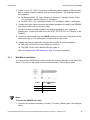
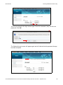
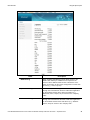
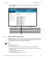
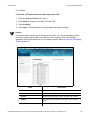
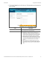
Ubee Interactive
Connecting Devices to the Network
The screws should protrude from the wall so that you can fit the device between the
head of the screw and the wall. If you install the screws in drywall, use hollow wall
anchors to ensure the unit does not pull away from the wall due to prolonged strain
from the cable and power connectors.
2. Mount the device on the wall.
2.2 Connecting Devices to the Network
Use the instructions below to connect network devices and validate device functionality.
Topics
See the following topics:
 Connecting an Ethernet Device on page 14
 Connecting a Wireless Device on page 15
2.2.1
Connecting an Ethernet Device
You can connect up to three additional Ethernet devices to the DDW366.
Steps
To connect another Ethernet device to the network:
1. Connect the Ethernet cable from the Ethernet device (for example, a PC or gaming
console) to an open Ethernet port on the back of the DDW366.
2. Use the device LEDs to confirm operations. Refer to Understanding LED Behavior on
page 5 for more information.
3. Open a Web browser and go to any Web site to validate network/Internet connectivity
(for example, http://www.wikipedia.org).
4. If the connected device is a gaming console, perform any online task supported by the
console (for example, log into the gaming server, play an online game, download
content).
Note
Refer to Troubleshooting the Installation on page 16 for troubleshooting information.
Ubee DDW366 Dual-Band Concurrent Advanced Wireless Gateway Subscriber User Guide • September 2014
14
Ubee Interactive
2.2.2
Connecting Devices to the Network
Connecting a Wireless Device
Use the following steps to connect a wireless device to the cable modem (for example, a
laptop computer).
Default values are shown in the steps below.
Steps
To connect a wireless device to the DDW366:
1. Access the wireless networking feature on your wireless device.
 Windows Users: Double-click the Wireless Network Connection icon in the system
tray (lower-right side of the Windows desktop). Click View Wireless Networks.
 Mac Users: Click on the wireless icon (Airport) on the right side of the top menu
bar. All available wireless networks will appear in the drop-down menu.
2. The DDW366 is shipped with a default SSID. The SSID is the name of the wireless
network broadcast from the device so that wireless clients can connect to it.
 Double-click your SSID in the wireless networks window. The default SSID is
“DDW366” plus a period, plus the last 6 characters of the Wi-Fi MAC address plus
“-2.4G.” In the 5GHz band, the SSID is the same as the 2.4GHz except add 1 hex
to the WiFi MAC address and change the end to “-5G.”
 Examples:
1. 2.4G radio with Wi-Fi MAC address F4:B7:E2:E5:C3:D2
SSID: DDW366.E5C3D2-2.4G
2. 5G radio with Wi-Fi MAC address F4:B7:E2:E5:C3:D2
SSID: DDW366.E5C3D3-5G
 Notes: If the subscriber changes the SSID, the device does not revert to this
default SSID when the device is reset, except when a factory reset is performed
through the Web UI. The Wi-Fi MAC address can be found at the top of the
Wireless Primary Network screen. Refer to Using the Primary Network Option on
page 70.
 When prompted, enter the network key, also called the WPA pre-shared key. This
is a unique key for each device. The pre-shared key for the DDW366 is the 13
characters of the modem’s serial number and can be found on the Wireless
Primary Network screen. Refer to Using the Primary Network Option on page 77.
The serial number can also be found on the device label. Refer to Understanding
the Device Label on page 10.
Ubee DDW366 Dual-Band Concurrent Advanced Wireless Gateway Subscriber User Guide • September 2014
15
Ubee Interactive
Troubleshooting the Installation
Example pre-shared key: C1V3X11000023
 If using WPS, enter the WPS personal identification number (PIN). The WPS PIN
is a randomly-generated number found on the Wireless Primary Network screen.
Refer to Using the Primary Network Option on page 77. The WPS PIN can also be
found on the device label. Refer to Understanding the Device Label on page 10.
 WPA-WPA2 TKIP+AES is the default encryption method.
3. Confirm connectivity by opening a Web browser and going to any Web site
(for example, http://www.wikipedia.org) or access the Web interface for the DDW366.
Note
The Web interface allows you to customize the configurations and capabilities for the
device. For a full explanation of all Web interface functions, refer to Using the Web
User Interface on page 16.
If you have wireless issues or questions, refer to Deploying and Troubleshooting the
Wireless Network on page 93.
2.3
Troubleshooting the Installation
Use the following tips to troubleshoot the installation.
 None of the LEDs are on when I power on the DDW366.
 Check the connection between the power outlet and the power cord. Verify the
power outlet is energized and the power cord is connected to the power outlet.
 Check the connection between the power cord and the cable modem. Power off
the cable modem and wait for 5 seconds and power on the modem again. If the
problem still exists, there may be a hardware problem.
 The ETH1, ETH2, ETH3, or ETH4 LEDs on the back of the modem are not lit
where Ethernet cables are connected.
 Restart the computer so that it can re-establish a connection with the cable
modem.
 Check for a resource conflict (Windows users only):
1.
Right-click My Computer on your desktop and choose Properties.
2.
Choose the Device Manager tab and look for a yellow exclamation point or red X over the
network interface card (NIC) in the Network Adapters field. If you see either one, you may
have an interrupt request (IRQ) conflict. Refer to the manufacturer’s documentation or ask
your service provider for further assistance.
 Verify that TCP/IP is the default protocol for your network interface card.
 Power cycle the cable modem by removing the power cord from the electrical
outlet and plugging it back in. Wait for the cable modem to re-establish
communications with your cable service provider.
 Check General Connectivity Issues:
 If your PC is connected to a hub or gateway, connect the PC directly into an
Ethernet port on the cable modem.
Ubee DDW366 Dual-Band Concurrent Advanced Wireless Gateway Subscriber User Guide • September 2014
16
Ubee Interactive
Troubleshooting the Installation
 If you are using a cable splitter, remove the splitter and connect the cable modem
directly to the cable wall outlet. Wait for the cable modem to re-establish
communications with the cable service provider.
 Try a different cable. The Ethernet cable may be damaged.
 If none of these suggestions work, contact your service provider’s tier II support for
further assistance.
Ubee DDW366 Dual-Band Concurrent Advanced Wireless Gateway Subscriber User Guide • September 2014
17
3
Using the Web User Interface
The Web user interface (UI) for the DDW366 is easy to use and allows you to view and
configure settings for your wireless gateway device. You can validate the installation by
accessing the Web user interface on the device.
Topics
See the following topics:
 Accessing the Web User Interface Locally on page 18
3.1
Accessing the Web User Interface Locally
Access the Web user interface for the DDW366 from a Web browser, such as Internet
Explorer on a Windows computer.
Default values are shown in the steps below.
Steps
To access the Web user interface:
1. Launch an Internet browser, such as Internet Explorer, from your computer.
2. Enter the following IP address in the address bar of the browser window and press the
Enter key.
http://192.168.100.1
3. Enter the username and password in the authentication dialog box.
 Standard User Web Interface Login:
Username: user
Password: user
4. Click OK. The Status>Software screen (shown below) displays software information
about the DDW366. After initially logging in to the device, you will be prompted to
change your password for security reasons. Refer to Changing the User Password on
Ubee DDW366 Dual-Band Concurrent Advanced Wireless Gateway Subscriber User Guide • September 2014
18
Ubee Interactive
Accessing the Web User Interface Locally
page 19 for detailed instructions on changing your password.
Note: Refer to Using the Software Option on page 21 for detailed field descriptions of
the Status>Software screen.
3.1.1
Changing the User Password
After successfully logging in to the DDW366 for the first time, the following pop-up window
will appear, prompting you to change your password for security purposes. Click OK.
The Status>Account screen will appear and allow you to enter a new password and then
confirm the new password. Click Apply.
Ubee DDW366 Dual-Band Concurrent Advanced Wireless Gateway Subscriber User Guide • September 2014
19
Ubee Interactive
Accessing the Web User Interface Locally
You will be returned to the login screen again. Enter the username (user) and the new
password. Click OK.
The Status>Account screen will appear again and will indicate that the password change
has been accepted.
Ubee DDW366 Dual-Band Concurrent Advanced Wireless Gateway Subscriber User Guide • September 2014
20
4
Understanding the Status Menu
The Status menu of the Web user interface allows you to access information about the
DDW366, such as software version, and connection (downstream and upstream) status. It
also allows you to change the username and password, perform diagnostic tests, and
reset user defaults.
Topics
See the following topics:





Using
Using
Using
Using
Using
the
the
the
the
the
Software Option on page 21
Connection Option on page 22
Account Option on page 25
Diagnostics Option on page 25
User Default Option on page 28
Steps
To access status options:
1. Access the Web user interface. Refer to Accessing the Web User Interface Locally on
page 16.
2. Click Status from the main menu.
4.1
Using the Software Option
The Software option displays the device’s internal software and hardware configuration.
Steps
To view software information:
1. Click Status from the main menu.
2. The Software screen is displayed. Field descriptions are listed below the screen
example.
Ubee DDW366 Dual-Band Concurrent Advanced Wireless Gateway Subscriber User Guide • September 2014
21
Ubee Interactive
Using the Connection Option
Label
Description
Information
Standard Specification Compliant
Defines the current DOCSIS standard of the device.
Hardware Version
Defines the internal version number that identifies the
hardware design.
Software Version
Defines the general software version of the device.
Cable Modem MAC Address
Defines the unique media access control (MAC) hardware
address of the DDW366.
Cable Modem Serial Number
Defines the unique manufacturer serial number of the device.
CM certificate
Indicates if the cable modem certificate is installed.
Status
4.2
System Up Time
Displays how long the device has been connected.
Network Access
Defines if network access is enabled. When enabled, the
user is allowed to access the network.
Using the Connection Option
The Connection screen displays information about the device’s connection status and
downstream and upstream channel bonding statistics.
 Downstream displays detailed information on the network traffic from the service
provider to the local computer (downstream channels).
 Upstream displays detailed information on the network traffic from the local
computer to the remote destination (upstream channels).
Ubee DDW366 Dual-Band Concurrent Advanced Wireless Gateway Subscriber User Guide • September 2014
22
Ubee Interactive
Using the Connection Option
Steps
To view connection information:
1. Click Status from the main menu.
2. Click Connection from the left side menu. Field descriptions are listed below the
screen example.
Ubee DDW366 Dual-Band Concurrent Advanced Wireless Gateway Subscriber User Guide • September 2014
23
Ubee Interactive
Using the Connection Option
Label
Description
Startup Procedure (Procedure, Status, Comment)
Acquire Downstream Channel
Displays the Downstream channel status and if the device has
locked to a channel.
Connectivity State
Displays connection status and if the DDW366 is operational.
Boot State
Displays the status on boot up and if the device is operational.
Configuration File
Provides the status and file name of the configuration file
currently used by the DDW366.
Security
Displays the status of the security settings: enabled/disabled.
Downstream Bonded Channels
Channel
Numbers the downstream channels.
Lock Status
Displays if the device has locked successfully to a
downstream channel.
Modulation
Displays the modulation method required for the downstream
channel to lock on to by the device. This method is
determined by the service provider.
Channel ID
Displays the downstream channel ID.
Frequency
Displays the downstream channel frequency on which the
device is locked.
Power
Displays the receiver power level in decibel millivolts (dBmV)
after ranging process.
SNR
Displays the signal-to-noise ratio (SNR) in decibels (dB), the
desired signal level to the background noise level.
Correctables
Displays the quantity of codewords which are correctable.
Uncorrectables
Displays the quantity of codewords which are not correctable.
Upstream Bonded Channels
Channel
Numbers the upstream channels.
Lock Status
Displays if the DDW366 succeeded in locking to an upstream
channel.
US Channel Type
Displays the channel type.
Channel ID
Displays the current upstream channel ID.
Symbol Rate
Displays the symbol rate in 1000 symbols per second.
Frequency
Displays the current cable modem upstream frequency in
hertz.
Power
Displays the current cable modem upstream transmit power in
decibel millivolts (dBmV).
Ubee DDW366 Dual-Band Concurrent Advanced Wireless Gateway Subscriber User Guide • September 2014
24
Ubee Interactive
4.3
Using the Account Option
Use the Account option to change the User username and password.
Steps
To reset the modem’s username and password:
1. Click Status from the main menu.
2. Click Account from the left side menu. Field descriptions are listed below the screen
example.
Label
Description
User
User name
Enter the new username.
New Password
Enter the new password.
Confirm Password
Confirm the new password by re-entering it.
Apply
Saves the changes.
Note: After changing the user password, you may be instructed to log into the
device again using the new password.
4.4
Using the Diagnostics Option
Use the Diagnostics option to test network connectivity. Two utilities are available: Ping
and Traceroute.
Topics
See the following topics:
 Using the Ping Option on page 26
 Using the Traceroute Option on page 27
Ubee DDW366 Dual-Band Concurrent Advanced Wireless Gateway Subscriber User Guide • September 2014
25
Ubee Interactive
4.4.1
Using the Diagnostics Option
Using the Ping Option
Use the Ping utility to test network connectivity between devices by sending a test
message to a specific device. You can also confirm that the size of data sent is the same
as the size of data received.
Steps
To test connectivity between devices:
1. Click Status from main menu.
1. Click Diagnostics from the left side menu.
2. Choose Ping from the Utility drop-down menu.
3. Enter new parameter values or accept the default values.
4. Click Start Test. Field descriptions are listed below the screen example.
Label
Description
Utility
Provides a drop-down menu to choose Ping or Traceroute.
Target
Defines the IP address to which you want to send a ping.
Ping Size
Defines the packet size (bytes of data) to send for the ping
operation. Default is 64.
No. of Pings
Defines the number of ping commands to send to the ping
target. Default is 3 pings.
Ubee DDW366 Dual-Band Concurrent Advanced Wireless Gateway Subscriber User Guide • September 2014
26
Ubee Interactive
Using the Diagnostics Option
Label
4.4.2
Description
Ping Interval
Defines the interval between ping operations in milliseconds.
Start Test
Abort Test
Clear Results
Defines what action to take.
 Start Test begins the ping.
 Abort Test stops the ping.
 Clear Results deletes previous test results in the Results
table.
Results
Displays the results of the ping test.
Using the Traceroute Option
The Traceroute utility determines the IP addresses of hosts in the network path. By
checking the Resolve Host names box, Traceroute tries to find which name matches the
address. Some hosts have no names, and might still be shown as IP addresses, even if
this option is active.
Steps
To trace host IP addresses along a route:
1. Click Status from main menu.
2. Click Diagnostics from the left side menu.
3. Choose Traceroute from the Utility drop-down menu.
4. Enter new parameter values or accept the default values.
5. Click Start Test. Field descriptions are listed below the screen example.
Ubee DDW366 Dual-Band Concurrent Advanced Wireless Gateway Subscriber User Guide • September 2014
27
Ubee Interactive
Using the User Default Option
Utility
Provides a drop-down menu to choose Ping or Traceroute.
Target
Defines the specific IP address or domain (for example,
ubeeinteractive.com) to which you want to trace a route.
Max Hops
Defines the maximum number of hops. Hops are the number
of routers the traceroute traverses. Default is 30.
Data Size
Defines the data size to send for the traceroute operation.
Default is 64.
Base Port
Defines the destination port number. Default is 33434.
Resolve Host
Enable (on) or disables (off) this option. When checked,
traceroute tries to find the name that matches the IP address.
Default is Off.
Start Test/Clear Results
Defines what you want to do.
Start Test begins the traceroute.
Clear Results deletes previous test results in the Results
table.


Results
4.5
Displays the results of the trace.
Using the User Default Option
The User Default option allows you to restore factory defaults to the Firewall and
Parental Control settings. All other networking settings are not cleared and reset (for
example, wireless settings).
Ubee DDW366 Dual-Band Concurrent Advanced Wireless Gateway Subscriber User Guide • September 2014
28
Ubee Interactive
Using the User Default Option
Steps
To restore user defaults:
1. Click Status from the main menu.
2. Click User Default from the left side menu. Field descriptions are listed below the
screen example.
Label
Description
Restore User Defaults
Restores settings to factory defaults. Select Yes, then Apply, to
have the device to the default Firewall and Parental Control
Content Filter settings. This operation does not require a reset
(power cycle) of the system.
Reset The System
Resets the system. Select Yes to power cycle the device.
When you select Apply, you will be notified that the device has
been reset. Click RELOAD. The Login screen will then appear.
Apply
Applies the options selected on the screen.
Ubee DDW366 Dual-Band Concurrent Advanced Wireless Gateway Subscriber User Guide • September 2014
29
5
Understanding the Basic Menu
Basic gateway options provide the majority of configuration for the device including WAN
IP addresses, LAN IP addresses, and DHCP. Advanced gateway options provide settings
like MAC filtering and port forwarding.
Topics
See the following topics:




Using
Using
Using
Using
the
the
the
the
Setup Option on page 30
DHCP Option on page 32
DDNS Option on page 34
Backup Option on page 35
Steps
To access the basic menu:
1. Access the Web user interface. Refer to Accessing the Web User Interface Locally on
page 16.
2. Click Basic from the main menu.
5.1
Using the Setup Option
Use the Setup option to configure common gateway parameters.
Steps
To configure setup options:
1. Click Basic from the main menu.
2. The Setup screen is displayed. Field descriptions are listed below the screen
example.
Ubee DDW366 Dual-Band Concurrent Advanced Wireless Gateway Subscriber User Guide • September 2014
30
Ubee Interactive
Using the Setup Option
Label
Description
LAN
IP Address
Defines the local IP address, which is the default gateway
address for all wired LAN hosts that connect to the DDW366.
MAC Address
Displays the LAN interface’s hardware address.
Interface/Prefix
None Specified
Indicates no interface or prefix has been specified.
WAN
IP Address
Displays the current WAN public IP address obtained from the
service provider.
MAC Address
Displays the WAN interface’s hardware address.
Duration
Displays the accumulated time since successfully acquiring a
WAN public IP address.
Expires
Displays the remaining time before the WAN IP address
expires, if applicable.
Release WAN Lease
Releases the WAN public IP address when clicked.
Renew WAN Lease
Renews the WAN IP address when clicked.
Ubee DDW366 Dual-Band Concurrent Advanced Wireless Gateway Subscriber User Guide • September 2014
31
Ubee Interactive
Using the DHCP Option
Label
5.2
Description
WAN Connection Type
Selects the WAN connection type. For each type, different data
entry is required, as explained below:
 DHCP: The WAN interface is set to a DHCP client, and
the IP address is assigned by the service provider’s DHCP
server.
 Static IP: For Static IP, you must manually enter the IP
address for the WAN interface.
 PPTP (dhcp): For Point to Point Tunneling Protocol
(PPTP), you must enter a username, password, and the
PPTP server’s IP address.
 PPTP (static):
 L2TP (dhcp):
 L2TP (static):
IPv4 MTU Size
Defines the maximum transmission unit (MTU) size. MTU
defines the largest size of the packet or frame that the device
can transfer (256-1500). If this is not given by your service
provider, use 0 for the default.
Apply
Saves changes.
Using the DHCP Option
Use the DHCP option to configure dynamic host configuration protocol-specific behavior
on the device.
Steps
To configure DHCP settings:
1. Click Basic from the main menu.
2. Click DHCP from the left side menu. Field descriptions are listed below the screen
example.
Ubee DDW366 Dual-Band Concurrent Advanced Wireless Gateway Subscriber User Guide • September 2014
32
Ubee Interactive
Using the DHCP Option
Label
Description
DHCP Server
Enables (Yes) or disables (No) DHCP on the device. If No is
selected, all the static DHCP rules in this screen are ignored.
Starting Local Address
Defines the starting private IP address for the pool of IP
addresses that can be used by connecting clients. Private
addresses are translated to public IPs to be used on the
network.
Number of CPEs
Defines the maximum number of customer premises
equipment devices (CPE) that can connect to the network
through the DDW366.
Lease Time
Defines the DHCP lease time duration in minutes between 1
and 71582788. A DHCP user's PC gets an IP address with a
lease time. When the lease time expires, the PC must connect
to the DHCP server and be issued a new unused IP address.
Note: The default DHCP lease time is 3600 seconds and
should be changed to 86400 seconds (24 hours). This helps
resolve connectivity issues with some iMAC and Windows 7
devices that turn off the network interface when they go into
standby mode. This results in slow Web browsing until the
device gets a new IP address via DHCP.
Apply
Saves changes.
Ubee DDW366 Dual-Band Concurrent Advanced Wireless Gateway Subscriber User Guide • September 2014
33
Ubee Interactive
Using the DDNS Option
Label
5.3
Description
DHCP Clients
Lists all DHCP clients currently connected to the device, either
via an Ethernet link, or via a wireless connection. Each client
is listed with the following information:
 MAC Address / IP Address / Subnet Mask
 Duration / Expires: Duration displays the accumulated
time since the client acquired the IP address. Expires is
the time until the IP expires and must be recycled. If the
IP address is reserved to a certain host, it shows STATIC
IP ADDRESS.
 Select: Reserves the current private IP address to be
assigned to this host statically when selected.
Current System Time
Displays the current system time.
Force Available
Activates a selected rule in the DHCP Clients list and assigns
IP addresses. Note: The Select button must be activated in the
DHCP list.
Using the DDNS Option
Use the dynamic domain name system (DDNS) to assign a changing IP address to a
constant pre-defined host name. The host can then be contacted by other hosts on the
Internet, even if its IP address changes.
The DDNS service for the DDW366 is provided through a third-party and can be
purchased from Dynamic Network Services Inc. at www.dynDNS.com.
Steps
To use the DDNS option:
1. Click Basic from the main menu.
2. Click DDNS from the left side menu. Field descriptions are listed below the screen
example.
Ubee DDW366 Dual-Band Concurrent Advanced Wireless Gateway Subscriber User Guide • September 2014
34
Ubee Interactive
Using the Backup Option
Label
5.4
Description
DDNS Service
Enables or disables the DDNS service. When enabled, this
service is available from www.dynDNS.org.
User Name
Defines the user name for the DDNS account.
Password
Defines the password for the DDNS account.
Host Name
Defines the host name for the DDNS account.
IP Address
Displays the IP address for the DDNS account.
Status
Displays if the DDNS service is enabled or disabled.
Apply
Saves changes.
Using the Backup Option
The Backup option lets you backup your gateway configuration or restore the DDW366 to
a previously saved configuration.
Steps
To use the backup option:
1. Click Basic from the main menu.
2. Click Backup from the left side menu.
5.4.1
Backing Up the Current Modem Configuration
To backup and save the current modem configuration, click the Backup button.
A pop-up window appears instructing you to select ‘Save’ when prompted. Click ‘OK’.
Ubee DDW366 Dual-Band Concurrent Advanced Wireless Gateway Subscriber User Guide • September 2014
35
Ubee Interactive
Using the Backup Option
The following window appears, giving you the option to save the file. Click the ‘Save File’
option and click ‘OK’.
The file will be saved to your Downloads folder as a binary file (.bin) titled
‘GatewaySettings.bin.’
5.4.2
Restoring the DDW366 to a Previously Saved Configuration
To restore the device to a previously saved configuration, click the Browse button.
The File Upload dialog box appears and allows you to select the previously saved backup
file. Highlight the file and click ‘Open’.
Ubee DDW366 Dual-Band Concurrent Advanced Wireless Gateway Subscriber User Guide • September 2014
36
Ubee Interactive
Using the Backup Option
The location for the backed up file appears in the box to the left of the Browse button.
Click the Restore button.
You are advised that you will be required to reboot the modem. Click ‘OK’.
You are then notified that the device has been reset. Click ‘RELOAD’.
Ubee DDW366 Dual-Band Concurrent Advanced Wireless Gateway Subscriber User Guide • September 2014
37
Ubee Interactive
Using the Backup Option
You are then presented with the login screen for the modem. Enter the Username and
Password to return to the modem User Interface.
Ubee DDW366 Dual-Band Concurrent Advanced Wireless Gateway Subscriber User Guide • September 2014
38
6
Understanding the Advanced Menu
Advanced options provide settings to configure your DDW366, such as MAC filtering and
port forwarding.
Topics
See the following topics:








Using
Using
Using
Using
Using
Using
Using
Using
the
the
the
the
the
the
the
the
Options Option on page 39
IP Filtering Option on page 42
MAC Filtering Option on page 43
Port Filtering Option on page 44
Forwarding Option on page 46
Port Triggers Option on page 50
Pass Through Option on page 54
DMZ Host Option on page 54
Steps
To access the Advanced menu:
1. Access the Web user interface. Refer to Accessing the Web User Interface Locally on
page 16.
2. Click Advanced from the main menu.
6.1
Using the Options Option
Use the Options option to define which networking protocols are enabled or disabled on
the device. The network address translation application-level gateway (NAT ALG) settings
provide additional security beyond the firewall.
Steps
To enable or disable network protocols:
1. Click Advanced from the main menu.
2. The Options screen is displayed. Field descriptions are listed below the screen
example.
Ubee DDW366 Dual-Band-Concurrent Advanced Wireless Gateway Subscriber User Guide • September 2014
39
Ubee Interactive
Using the Options Option
Label
Description
WAN Blocking
When enabled, WAN Blocking blocks PING access to the
WAN Public Gateway IP address that is exposed to the
Internet. When disabled, PING access is allowed to occur,
which is necessary for the remote configuration of some VoIP
phones (e.g., Cisco, Polycom).
Ipsec PassThrough
When enabled, allows encrypted IPsec VPN traffic to pass
through the router between the IPsec VPN Client application
on the PC/Mac and the IPsec VPN Concentrator (e.g.,
Barracuda, Cisco, Juniper, etc) for access to the “company
VPN.”
PPTP PassThrough
When enabled, allows encrypted PPTP VPN traffic to pass
through the router between the PPTP VPN Client application
on the PC/Mac and the PPTP VPN Server (e.g., Windows
Server, 2013) for access to the “company VPN.”
Ubee DDW366 Dual-Band-Concurrent Advanced Wireless Gateway Subscriber User Guide • September 2014
40
Ubee Interactive
Using the Options Option
Label
Description
Remote Config Management
Enables or disables access to the device from a remote
system in order to configure settings. Remote management
can be achieved by using SNMP, web/HTTP or telnet.
Multicast Enable
Optimizes the bandwidth utilization compared with unicast
(especially video streaming applications).
UPnP Enable
Activates Universal Plug and Play (UPnP) when enabled. A
UPnP device can dynamically join a network, obtain an IP
address, convey its capabilities, and learn about other devices
on the network. In turn, a device can leave a network smoothly
and automatically when it is no longer in use. Gaming
consoles and Web cameras are examples of devices that can
use UPnP.
Primary Network Bridged
When enabled, all wireless traffic sourced from the primary
SSID will be bridged.
NAT ALG Status – Filters to allow (enable) or disallow (disable) protocols to pass through the
DDW366 to connected devices (computers, game consoles, and so on).
RSVP
Enables or disables resource reservation protocol (RSVP).
RSVP defines how applications reserve resources and how
they free the reserved resources once they are no longer
needed.
FTP
Enables or disables the file transfer protocol (FTP) used to
transfer files from one host to another.
TFTP
Enables or disables the trivial file transfer protocol (TFTP) – a
simpler protocol generally used for automated file transfers.
Kerb88
Enables or disables the Kerberos network authentication
protocol which allow nodes to communicate over a non-secure
network using “tickets” on port 88 to prove their identity to one
another.
NetBios
Enables or disables the network basic input/output system
(NetBIOS) services related to the OSI session layer. NetBIOS
allows applications on separate computers to communicate
over a LAN.
IKE
Enables or disables the network key exchange (IKE) protocol
used to set up a security association (SA) in the IPsec protocol
suite.
RTSP
Enables or disables the real time streaming protocol (RTSP)
network control protocol used to establish and control media
sessions between end points.
Kerb1293
Enables or disables the Kerberos network authentication
protocol which allows nodes to communicate over a nonsecure network using “tickets” on port 1293.
H225
Enables or disables the H.225 protocol used to define
messages and procedures for call signaling, media
packetization, and registration, admission, and status (RAS)
functions.
Ubee DDW366 Dual-Band-Concurrent Advanced Wireless Gateway Subscriber User Guide • September 2014
41
Ubee Interactive
Using the IP Filtering Option
Label
Description
PPTP
Enables or disables the point-to-point tunneling protocol
(PPTP) used to implement a virtual private network.
MSN
Enables or disables the Microsoft network protocol used for
instant messaging.
SIP
Enables or disables the session initiation protocol application
layer gateway (SIP ALG). SIP ALG inspects protocol
packets and formats SIP message headers and SDP
body to ensure proper signaling. Note: Some hosted VoIP
services prefer this function to be performed by their own
session border controller (SBC) and require the SIP ALG to be
disabled. Some IP-PBXs may require SIP ALG enabled.
6.2
ICQ
Enables or disables the ICQ instant messaging program.
IRC666x
Enables or disables the Internet relay chat (IRC) protocol used
for text messaging.
ICQTalk
Enables or disables the ICQTalk instant messaging program.
Net2Phone
Enables or disables Net2Phone SIP- and PacketCable-based
VoIP.
IRC7000
Enables or disables the Internet relay chat protocol on TCP
port TCP 7000 used for text messaging and group forums.
IRC8000
Enables or disables the Internet relay chat protocol on UDP
port 8000 used for text messaging and group forums.
Apply
Saves changes.
Using the IP Filtering Option
Use the IP Filtering option to filter IP addresses to block Internet traffic to specific
network devices on the LAN. Any host on this list is not accessible to Internet traffic.
Note
You may also filter by the MAC address which does not require setting a static lease.
Refer to Using the MAC Filtering Option on page 43.
Steps
To filter IP addresses:
1. Make sure a PC is connected to the cable modem and both devices are powered on
and functioning.
2. Log in to the cable modem’s Web user interface. Refer to Accessing the Web User
Interface Locally on page 16.
3. Click Advanced from the main menu.
Ubee DDW366 Dual-Band-Concurrent Advanced Wireless Gateway Subscriber User Guide • September 2014
42
Ubee Interactive
Using the MAC Filtering Option
4. Click IP Filtering from the left side menu. Field descriptions are listed below the
screen example.
Label
6.3
Description
Start Address
Defines the starting IP address to block.
End Address
Defines the ending IP address to block.
Enabled
Activates the rule when Enabled is checked.
Apply
Saves changes.
Using the MAC Filtering Option
The MAC Filtering option allows you to filter MAC addresses to block Internet traffic from
specific network devices on the LAN. MAC filtering establishes a list and any host on this
list is not able to access the network through the DDW366.
Steps
To filter MAC addresses:
1. Note the MAC address of the devices that you want to deny Internet access.
Be sure all devices to which you potentially deny Internet access are connected to the
DDW366 network.
2. Click Advanced from the main menu.
3. Click MAC Filtering from the left side menu.
Ubee DDW366 Dual-Band-Concurrent Advanced Wireless Gateway Subscriber User Guide • September 2014
43
Ubee Interactive
Using the Port Filtering Option
4. Enter the MAC address to block in the text box to the left of the Add MAC Address
button.
5. Click the Add MAC Address button. The MAC address is displayed in the filtered
MAC address list. Field descriptions are listed below the screen example.
Label
6.4
Description
MAC Addresses
Defines the MAC address to block. Enter the MAC address in
the field.
Add MAC Address
Adds the MAC address to the list of addresses to block.
Addresses entered: n/20
Displays the MAC addresses to be blocked. The number of
MAC addresses entered is shown as 1/20 where 1 is the
number of addresses in the list. You can filter up to twenty
MAC addresses at one time.
Remove MAC Address
Deletes the selected MAC address from the list of addresses
to be blocked.
Clear All
Removes all MAC addresses from the list.
Using the Port Filtering Option
Use the Port Filtering option to configure port filters to block to all devices on the LAN
Internet services that use the ports specified.
Steps
To configure port filters:
1. Click Advanced from the main menu.
2. Click Port Filtering from the left side menu. Field descriptions are listed below the
screen example.
Ubee DDW366 Dual-Band-Concurrent Advanced Wireless Gateway Subscriber User Guide • September 2014
44
Ubee Interactive
Using the Port Filtering Option
For example:
To prevent all Telnet access into and across your LAN:
1. Enter the Start and End ports to be 23.
2. Select Both for Protocol to include TCP and UDP.
3. Check Enabled.
4. Click Apply. Field descriptions are listed below the screen example.
Caution
Use caution when assigning port filtering by port range. You may accidentally prevent
traffic that should pass through your network, such as http or email. Pre-assigned
application ports are displayed on the Forwarding screen. Refer to Using the Forwarding
Option on page 46.
Label
Description
Start Port
Defines the starting port number
End Port
Defines the ending port number.
Protocol
Selects the protocol type. Options are UDP, TCP, or Both.
Enabled
Activates the rule and filters out all traffic on the specified
ports.
Apply
Saves changes.
Ubee DDW366 Dual-Band-Concurrent Advanced Wireless Gateway Subscriber User Guide • September 2014
45
Ubee Interactive
6.5
Using the Forwarding Option
Forwarding tells the DDW366 to which computer on the local area network to send data.
If your host systems or applications have communications issues with the Internet, you
can use forwarding to resolve the following issues:
 Data is sent from a local host to the Internet, but the return path of expected data is
not received by your local host.
 An application or service running on your local network (on local host) cannot be
accessed from the Internet directly (for example, a request to a local audio server).
Examples are:
 Xbox/PlayStation – Games/applications
 Home Security Systems – Security systems that use the Internet
 Audio Servers/VoIP – Audio and VoIP applications and services
Topics
See the following topics:
 Before Setting Up Forwarding on page 46
 Setting Up Forwarding on page 47
 Setting Up Forwarding for an Xbox Example on page 49
6.5.1
Before Setting Up Forwarding
Try the following options before you assign forwarding rules:
1. Enable Universal Plug and Play (UPnP). This may resolve the issue you have without
setting up forwarding rules.
a. Access the Web interface of the DDW366, see Accessing the Web User Interface
Locally on page 16.
b. Click Advanced from the main menu.
c. The Options screen is displayed. Check the Enable UPnP box.
.
d. Click Apply.
e. Test your local host or application such as your Xbox to see if it is functioning
properly. Continue with port forwarding if the host or application is not
communicating correctly.
2. Assign a Static IP lease to the client/host to which you are setting up forwarding. This
Ubee DDW366 Dual-Band-Concurrent Advanced Wireless Gateway Subscriber User Guide • September 2014
46
Ubee Interactive
Using the Forwarding Option
way, the IP does not change and disrupt your forwarding rules. For example, if you are
hosting a Web server in your internal network, and you wish to setup a forwarding rule
for it, assign a static IP lease to that system to keep the IP from renewing and
disrupting the forwarding rule.
6.5.2
Setting Up Forwarding
If the suggestions in Before Setting Up Forwarding on page 46 did not correct your
communication problem, use port forwarding.
You need the following information to set up port forwarding:
 IP address of each local host system (for example, Xbox) for which you need to setup
a port forwarding rule.
 Port numbers the local host’s application listens to for incoming requests/data (for
example, a game or other service). These port numbers should be available in the
documentation associated with the application.
Note
For detailed information on port forwarding, including how to set it up for specific
applications using specific network devices (for example, cable modems), refer to:
http://portforward.com or consult your host device or application user manual.
Steps
To set up forwarding:
1. Access the Web interface of the cable modem, see Accessing the Web User Interface
Locally on page 16.
2. Click Advanced from the main menu.
3. Click Forwarding from the left menu.
4. Click Create IPv4
Ubee DDW366 Dual-Band-Concurrent Advanced Wireless Gateway Subscriber User Guide • September 2014
47
Ubee Interactive
Using the Forwarding Option
5. Enter information in the forwarding fields as shown in the screen shot below. Field
descriptions follow.
Label
Description
Local IP Address
Defines the IP address of the local LAN device to which the
forwarding rule applies. For example, an Xbox or PC.
Local Start Port
Defines the starting port number listened to by the server host
located in your LAN.
Local End Port
Defines the ending port number listened to by the server host
located in your LAN.
External IP Address
Designates another router on the network through which to
forward data.
External Start Port
Defines the port number to start the range of ports to publish
to the Internet.
External End Port
Defines the port number to end the range of ports published to
Internet.
Note: Be very careful with ranges. Ports within a range are not
usable by other applications that may require them. It is
common and safer to enter the same port number as the start
and end of the range.
Protocol
Selects the protocol type. Options are UDP, TCP, or BOTH.
Description
Names the forwarding rule.
Enabled
Disables (Off) or enables (On) the forwarding rule.
Cancel
Stops creating the forwarding rule and returns you to the
previous Forwarding screen.
Apply
Saves changes.
Ubee DDW366 Dual-Band-Concurrent Advanced Wireless Gateway Subscriber User Guide • September 2014
48
Ubee Interactive
Using the Forwarding Option
Shows a list of common applications and their ports.
Port Map
Forwarding Table – Lists existing forwarding rules.
Deletes all entries in the forwarding table.
Remove All
6. Click Apply. The forwarding rule is created and displayed in the table as shown
below. Additional field descriptions follow.
Label
6.5.3
Description
Edit
Displays fields for the rule selected in order to change values.
Remove
Deletes the rule selected.
Setting Up Forwarding for an Xbox Example
Following is an example of how you would set up a single Xbox running Modern
Warfare 2. Since multiple ports are used for the Xbox and the Modern Warfare 2 game, a
separate forwarding rule is set for each port. Multiple ports and forwarding rules may not
be required for other applications.
Steps
To set up port forwarding for an Xbox:
1. Click Advanced from the main menu.
2. Click Forwarding from the left side menu.
3. Enter the Xbox IP address in the Local IP field.
4. Define ports used by the Xbox in the Local Start Port and Local End Port fields.
Define the same ports used by the Xbox in the External Start Port and External End
Port fields.
5. Create Port Forwarding rules per port. A rule set up for port 53 works for port 53. A
Ubee DDW366 Dual-Band-Concurrent Advanced Wireless Gateway Subscriber User Guide • September 2014
49
Ubee Interactive
Using the Port Triggers Option
port can be used only by one program at a time.
Note
You can set up applications/services to listen on one internal port. External Internet
users who want to access that application, address it using an external port, such as
an Audio server. Internal Ports are the ports to which local servers listen. External
Ports are the ports that the DDW366 listens to from the WAN.
The following screen shot shows Forwarding set up for an Xbox.
6.6
Using the Port Triggers Option
Port Triggers define dynamic triggers to specific devices on the LAN. This allows special
applications that require specific port numbers with bi-directional traffic to function
properly. Applications such as video conferencing, voice, gaming, and some messaging
program features may require these special settings.
Some services use a dedicated range of ports on the client side and a dedicated range of
ports on the server side. The difference between port forwarding and triggering is:
 Port forwarding sets a rule to send a service to a single LAN IP address.
 Port triggering defines two kinds of ports: trigger port and target port. The trigger
port sends a service request from a LAN host to a specific destination port number.
The port the LAN host is required to listen to by the application is called the target
port. The server returns responses to these ports.
For example:
1. John requests a file from the Real Audio server (port 7070). Port 7070 is a “trigger”
port and causes the device to record John’s computer IP address. The DDW366
associates John's computer IP address with the “target” port range of 6970-7170.
2. The Real Audio server responds to a port number ranging between 6970-7170.
Ubee DDW366 Dual-Band-Concurrent Advanced Wireless Gateway Subscriber User Guide • September 2014
50
Ubee Interactive
Using the Port Triggers Option
3. The DDW366 forwards the traffic to John’s computer IP address.
4. Only John can connect to the Real Audio server until the connection is closed or
expires.
Steps
To set up port triggering:
1. Click Advanced from the main menu.
2. Click Port Triggers from the left side menu.
3. Click Create.
4. Enter information in the Port Trigger fields as shown below. Field descriptions follow
the screen shot.
Ubee DDW366 Dual-Band-Concurrent Advanced Wireless Gateway Subscriber User Guide • September 2014
51
Ubee Interactive
Using the Port Triggers Option
Label
Description
Trigger Start Port
Defines a port number or the starting port number in a range
of trigger port numbers.
Trigger End Port
Defines a port number or the ending port number in a range of
trigger port numbers.
Target Start Port
Defines a port number or the starting port number in a range
of target port numbers.
Target End Port
Defines a port number or the ending port number in a range of
target port numbers.
Protocol
Defines the protocol type for this rule, UDP, TCP, or Both.
Description
Names the triggering rule.
Enabled
Enables (on) or disables (off) the triggering rule.
Apply
Saves changes.
Clear All
Removes all of the input host’s MAC addresses.
5. Click Apply. The port trigger rule is created and displayed in the table. Additional field
descriptions are listed below the screen example.
Ubee DDW366 Dual-Band-Concurrent Advanced Wireless Gateway Subscriber User Guide • September 2014
52
Ubee Interactive
Using the Port Triggers Option
Label
Description
Remove All
Deletes all the port trigger rules.
Edit
Allows you to edit the properties of the selected rule.
Remove
Deletes the selected rule.
Clear All
Removes all of the input host’s MAC addresses.
The following example shows the Port Triggering option set up for a dual Xbox
configuration.
Ubee DDW366 Dual-Band-Concurrent Advanced Wireless Gateway Subscriber User Guide • September 2014
53
Ubee Interactive
6.7
Using the Pass Through Option
Use the Pass Through option to configure a pass through table. Devices in the pass
through table are treated as bridge devices, storing and forwarding data between LAN
interconnections.
Steps
To configure a pass through table:
1. Click Advanced from the main menu.
2. Click Pass Through from the left side menu. The pass through fields are explained
following this screen example.
Label
6.8
Description
Pass Through MAC Addresses
Defines the input host’s MAC address.
Add MAC Address
Adds the input host’s MAC address.
Addresses entered: n/32
Displays the MAC addresses to be blocked. The number of
MAC addresses is shown as 0/32 where 0 is the number of
addresses in the list. You can add up to 32 MAC addresses at
one time.
Remove MAC Address
Removes the input host’s MAC address.
Clear All
Removes all of the input host’s MAC addresses.
Using the DMZ Host Option
Use the DMZ (Demilitarized Zone) Host option to expose a host IP address to the WAN
(public Internet). You can use this option when applications do not work with port triggers
or other networking strategies.
Ubee DDW366 Dual-Band-Concurrent Advanced Wireless Gateway Subscriber User Guide • September 2014
54
Ubee Interactive
Using the DMZ Host Option
Steps
To set up a DMZ host:
1. Connect a PC to an Ethernet port on the DDW366. Make sure both devices are
powered on and functioning.
2. Connect a Home Gateway (or other device you wish to be in the DMZ) to an Ethernet
port on the DDW366.
3. Log in to the DDW366 Web user interface.
4. Click Advanced from the main menu.
5. Click DMZ Host from the left side menu.
6. Enter the IP address of the Home Gateway (host device) to be exposed to the WAN.
7. Test the device to ensure Internet access is available and the device is functional. For
example, connect to the Internet from a PC connected to the Home Gateway.
Label
Description
DMZ Address
Defines the IP address of the host to be exposed.
Apply
Saves changes.
Ubee DDW366 Dual-Band-Concurrent Advanced Wireless Gateway Subscriber User Guide • September 2014
55
7
Understanding the Firewall Menu
Use these instructions to configure the DDW366 firewall settings to control what types of
traffic are allowed on your network. The firewall can block certain Web-oriented cookies,
Java scripts, and pop-up windows. It is highly recommended the Firewall is left enabled at
all times to protect against denial of service (DoS) attacks. Refer to Using the Basic Option
on page 56 to block Internet access to specific sites.
Note: Firewall menu options are not available when the DDW366 is in Bridge mode. Refer
to Using the Bridging Option on page 81 for more information.
Topics
See the following topics:
 Using the Basic Option on page 56
 Using the Local Log Option on page 57
 Using the Remote Log Option on page 58
Steps
To access the firewall menu:
1. Access the Web user interface. Refer to Accessing the Web User Interface Locally on
page 16.
2. Click Firewall from the main menu.
7.1
Using the Basic Option
Use the Basic option to filter Web content to block certain Web-oriented cookies, Java
scripts, and pop-up windows.
Steps
To filter Web content:
1. Click Firewall from the main menu.
2. The Basic screen is displayed. Field descriptions are listed below the screen
example.
Ubee DDW366 Dual-Band Concurrent Advanced Wireless Gateway Subscriber User Guide • September 2014
56
Ubee Interactive
Using the Local Log Option
Label
7.2
Description
IPv4 Firewall Protection
Defines the level of protection. Choices are Off, Low, Medium,
and High. Services are based on the protection level and
displayed in the Allowed Services window.
Port Scan Detection
When enabled, detects port scans that probe for available
ports and potentially use these ports to detect weakness in the
network.
Optimize for XBOX
When enabled, this feature stabilizes and improves video
streaming.
Apply
Saves changes.
Using the Local Log Option
Use the Local Log to define firewall event log reporting through email alerts and report on
possible attacks on the system.
Steps
To define local log reporting:
1. Click Firewall from the main menu.
2. Click Local Log from the left side menu. Field descriptions are listed below the screen
example.
Ubee DDW366 Dual-Band Concurrent Advanced Wireless Gateway Subscriber User Guide • September 2014
57
Ubee Interactive
Using the Remote Log Option
Label
7.3
Description
Contact Email Address
Defines the email address where you want to send the log.
SMTP Server Name
Defines the name of the SMTP server, such as
smtp.example.com.
SMTP Username
Defines the username for the email address, such as
[email protected].
SMTP Password
Defines the password for the email address.
E-mail Alerts
Enables or disables log reporting.
Apply
Saves the settings and completes the setup.
E-mail Log
Sends the log to the specified email address.
Clear Log
Deletes the log.
Using the Remote Log Option
Use the Remote Log option to define events and send the log to a local SysLog server.
Steps
To configure the firewall remote log:
1. Click Firewall the main menu.
2. Click Remote Log from the left side menu. The Remote Log fields are explained
following this screen example.
Ubee DDW366 Dual-Band Concurrent Advanced Wireless Gateway Subscriber User Guide • September 2014
58
Ubee Interactive
Using the Remote Log Option
Label
Description
Permitted Connections
Logs all access attempts that are allowed by the firewall when
checked.
Blocked Connections
Logs all access attempts that are blocked by the firewall when
checked.
Known Internet Attacks
Logs all known attacks from the Internet when checked.
Product Configuration Events
When checked, logs when the DDW366 is configured/modified
by a user or administrator.
to SysLog server at 192.168.0.
Defines the IP address of the Syslog server.
Apply
Saves changes.
Ubee DDW366 Dual-Band Concurrent Advanced Wireless Gateway Subscriber User Guide • September 2014
59
8
Understanding the Access Control Menu
The Access Control menu allow you to control Internet access for users on the DDW366
network. It provides the following features:




Define user/password access.
Block specific Web sites and Web sites based on keywords.
Define the times users are allowed to access the Internet.
View a local log to view Internet activity.
Topics
See the following topics:




Using
Using
Using
Using
the
the
the
the
User Setup Option on page 60
Basic Option on page 62
ToD Filter Option on page 64
Local Log Option on page 66
Steps
To access the Access Control menu:
1. Access the Web interface. Refer to Accessing the Web User Interface Locally on page
16.
2. Click the Access Control link from the top of the screen.
8.1
Using the User Setup Option
The User Setup option allows you to configure which user accounts can or cannot
connect to your wireless or wired network, and the parameters of each connection.
Steps
To configure user accounts:
1. Click the Access Control link from the top of the screen.
2. The User Setup screen is displayed. Field descriptions follow the screen shot below.
Note: To enable Access Control, refer to Using the Basic Option on page 62.
Ubee DDW366 Dual-Band Concurrent Advanced Wireless Gateway Subscriber User Guide • September 2014
60
Ubee Interactive
Label
Description
Add User
Remove User
Enable
Defines user accounts.
 To add a new user, add the user name and click Add
User. The user becomes selectable in the User Settings
drop down menu.
 To select an existing user, choose the user from the User
Settings drop down menu.
 To activate the user, check Enable.
 To remove a user, select the user from the User Settings
drop down menu and click Remove User.
Password
Defines the password for this user. It is required when this
user tries to access the Internet via the device.
Re-Enter Password
Confirms the password with the re-entered password.
Trusted User
Defines the selected user as a trusted user when enabled is
checked. The user is limited to timing and content when
visiting the Internet, as defined in the following fields.
Content Rule
Selects from the pop-up menu an existing content rule that
defines what kind of Websites the user can visit or not.
White List Access Only
Selects the White List Access option. If you have created a
content rule that defines a black list and white list, select the
White List Access Only checkbox to force the wireless modem
to execute the policy for the selected user.
Ubee DDW366 Dual-Band Concurrent Advanced Wireless Gateway Subscriber User Guide • September 2014
61
Ubee Interactive
Label
8.2
Description
Time Access Rule
Selects a defined time access rule to apply to the selected
user.
Session Duration
Allows you to enter a time in minutes for the user’s session to
expire. When the session expires, the user can log in again for
the same session duration.
Inactivity Time
Allows you to enter the time out value when a user has no
activity on the Internet. When the time expires, the user
interface to the Internet is canceled.
Apply
Saves all changes when clicked.
Trusted Computers
Defines the trusted hosts that can bypass the Access Control
Process.
Add
Adds the trusted host’s MAC address entered in the given
area and Add is clicked.
Remove
Removes a trusted computer from the list when it is
highlighted and Remove is clicked.
Using the Basic Option
The Basic option allows you to select rules to block certain Internet content and Web
sites. After you change your Access Control settings, click the appropriate Apply, Add, or
Remove button for your new settings to take effect. Refresh your browser’s display to see
the currently active settings.
Steps
To filter Internet content and Web sites:
1. Click the Access Control link from the top of the screen.
2. Click Basic from the left side of the screen. The Basic fields are explained following
this screen example.
Ubee DDW366 Dual-Band Concurrent Advanced Wireless Gateway Subscriber User Guide • September 2014
62
Ubee Interactive
Label
Description
Enable Access Control
Activates the Access Control feature when checked.
Apply
Saves all changes in the screen and activates Access Control,
if enabled.
Content Policy Configuration
Add New Policy
Adds a policy to the Policy List. Enter the policy name and
click Add New Policy. The policy then becomes selectable in
the Content Policy List drop down menu.
Content Policy List
Lists existing policies you can choose to use.
Remove Policy
Deletes a policy from the list. Select the policy from the
Content Policy List drop down menu and click Remove Policy.
Keyword List
Displays keywords you can use to block Web site addresses
(URLs) containing those words.
Add Keyword
Adds a keyword to the keyword list. Enter the word in the field
next to the Add Keyword button and click Add Keyword. The
keyword is added to the Keyword List.
Ubee DDW366 Dual-Band Concurrent Advanced Wireless Gateway Subscriber User Guide • September 2014
63
Ubee Interactive
Label
Remove Keyword
Removes a keyword from the keyword list. Select the keyword
from the Keyword List, and click Remove Keyword.
Blocked Domain List
Displays Web domains (for example, unwanted.com) you can
use to block access to those domains.
Add Domain
Adds a domain to the Blocked Domain List. Enter a domain in
the field next to the Add Domain button, and click Add Domain.
Remove Domain
Removes a domain from the Blocked Domain List. Select the
domain from the Blocked Domain List, and click Remove
Domain.
Allowed Domain List
Displays domains you want to allow access to.
Add Allowed Domain
Adds allowed domains to the list. Enter the name in the field
next to Add Allowed Domain and click Add Allowed Domain.
Remove Allowed Domain
Removes domain names from the Allowed Domain List.
Highlight the domain from the list and click Remove Allowed
Domain.
Override Password
8.3
Description
If you encounter a blocked website, you can override the block
by entering a password.
Password
Enter a password for overriding blocked websites.
Re-Enter Password
Re-enter the password.
Access Duration
Set a time duration (in minutes) for access to the blocked site
when the block has been overridden by entering the password.
Apply
Saves the password and access duration time.
Using the ToD Filter Option
The ToD (Time of Day) Filter option allows the configuration of time-based access
policies to block all Internet traffic at specified times.
Steps
To configure ToD filters:
1. Click the Access Control link from the top of the screen.
2. Click ToD Filter from the left side of the screen. The ToD Filter fields are explained
following this screen example.
Ubee DDW366 Dual-Band Concurrent Advanced Wireless Gateway Subscriber User Guide • September 2014
64
Ubee Interactive
Label
Description
Add New Policy
Adds a new policy. Enter a policy name in the field next to Add
New Policy, and click the Add New Policy button. The policy
then becomes selectable in the Time Access Policy List drop
down menu.
Time Access Policy List
Lists the existing policies in a drop-down menu.
Enabled
Activates a policy. Select the policy from the Time Access
Policy List drop-down menu and check Enabled.
Remove
Deletes a policy. Select the policy from the Time Access Policy
List drop-down menu and click Remove.
Days to Block
Allows you to select the days to block Internet access.
Time to Block:
All Day or a specific time frame
Allows you to define the times of day to block.
 To block all day, check All Day to eliminate all access
during the days selected.
 To define a specific time frame to block Internet access for
the days selected, enter the Start time and the End time.
Select AM or PM for each.
Ports to Block
Defines a port range to block if the Enabled box is checked.
 Port Start: Enter the starting port number to be blocked.
 Port End: Enter ending port number to be blocked.
 Protocol: Select the protocol type. Options are UDP, TCP,
or Both.
Apply
Saves all changes when clicked.
Ubee DDW366 Dual-Band Concurrent Advanced Wireless Gateway Subscriber User Guide • September 2014
65
Ubee Interactive
8.4
Using the Local Log Option
The Local Log option displays Access Control event log reporting.
Steps
To view the access control local log:
1. Click the Access Control link from the top of the screen.
2. Click Local Log from the left side of the screen. The Local Log fields are explained
following this screen example.
Label
Description
Last Occurrence
Displays the time when the last event occurred.
Action
Displays what is done by access control, including dropping or
permitting access requests.
Target
Displays the destination IP address of a certain access
request.
User
Displays the user who triggered this event log.
Source
Displays the source IP address of this event.
Clear Log
To empty the displayed log entries, click Clear Log.
Ubee DDW366 Dual-Band Concurrent Advanced Wireless Gateway Subscriber User Guide • September 2014
66
9
Understanding the Wireless Menu
Use the Wireless menu to configure wireless network settings.
Topics
See the following topics:







Using the Wireless Radio Option on page 67
Using the Primary Network Option on page 70
Using the Advanced Option on page 75
Using the Access Control Option on page 76
Using the Wi-Fi Multimedia Option on page 78
Using the Bridging Option on page 81
Deploying and Troubleshooting the Wireless Network on page 82
Steps
To access the Wireless menu:
1. Access the Web interface. Refer to Accessing the Web User Interface Locally on page
16.
2. Click Wireless from the main menu.
9.1
Using the Wireless Radio Option
The Radio option is used to configure the wireless radio, including channel number, and
bandwidth control.
IMPORTANT NOTE: The DDW366 is a dual-band concurrent wireless gateway,
supporting operation of both the 2.4GHz and 5GHz radio bands simultaneously. On the
The Wireless Radio screen, the “Wireless Interfaces” drop down enables you to select the
radio you wish to configure settings for (i.e. changing the SSID name or password). The
selected band will then be reflected in the “802.11 Band” field. This control is only an
indicator of which band you are configuring, both the 2.4GHz and 5GHZ radios will be
enabled automatically.
Steps
To configure wireless operations:
1. Click Wireless from the main menu.
2. The Radio screen is displayed. Field descriptions are listed below the screen
example.
Ubee DDW366 Dual-Band Concurrent Advanced Wireless Gateway Subscriber User Guide • September 2014
67
Ubee Interactive
Using the Wireless Radio Option
Label
Wireless Interfaces
Description
This field allows you to select one of the two radios (2.4GHz
or 5GHz) to actively configure settings for. It displays the
SSID for either the 2.4GHz or 5GHz radio (either the default
SSID or the SSID that has been assigned). This example
shows the setting when the user has chosen to configure
settings for the 2.4GHz band. After selecting Apply, the user
can then return to this field and configure settings for the
5GHZ radio. Refer to Understanding Default Values and
Logins on page 8 for more information on the SSID.
NOTE: The DDW366 is a dual-band concurrent wireless
gateway, supporting operation of both the 2.4GHz and 5GHz
radio bands simultaneously.
Wireless
Displays the wireless radio’s status, Enabled or Disabled.
Country
Defines the country where this device is used. The default
value is Q2.
Output Power
Output power setup can be one of the following 4 options:
25%, 50%, 75%, or 100%.
802.11 Band
Displays which 802.11 band (either 2.4GHz or 5GHz) is
currently being configured.
NOTE: The DDW366 is a dual-band concurrent wireless
gateway, supporting operation of both the 2.4GHz and 5GHz
radio bands simultaneously.
802.11 n-mode
Sets the wireless networking standard. Select Auto to use
802.11 n mode when possible. This mode has a significant
increase in the maximum raw OSI physical layer data rate
from 54 Mbit/s to a maximum of 600 Mbit/s with the use of
four spatial streams when at a channel width of 40 MHz.
Ubee DDW366 Dual-Band Concurrent Advanced Wireless Gateway Subscriber User Guide • September 2014
68
Ubee Interactive
Using the Wireless Radio Option
Label
9.1.1
Description
802.11 N Support Required
Defines whether 802.11n support is required (on) or not (off).
On forces the gateway to 802.11n mode and clients must
support 802.11n.
Bandwidth
Sets the bandwidth to 20MHz or 40MHz. For 40 MHz, set the
sideband to lower or upper 20MHz. 40 MHz channels double
the channel width. This allows doubling the PHY data rate
over a single 20 MHz channel.
Sideband for Control Channel
Only when using 40MHz Bandwidth should you choose the
Lower or Upper 20MHz.
Control Channel
Selects a specific channel to deploy the wireless network.
This allows you to set the operating frequency/channel
depending on your particular region. Channel selection can
have an impact on wireless networking performance. Control
Channel is set to Auto by default. For more information, refer
to Selecting a Wireless Channel on page 86
Regulatory Mode
Defines whether Regulatory Mode is set to off, 802.11d, or
802.11h.
TPC Mitigation (dB)
Defines the transmitter power control (TPC) mitigation setting
as 0 (off), 2, 3, or 4.
OBSS Coexistence
Enables or disables overlapping BSS coexistence.
STBC Tx
Sets the space-time block codes (STBCs) for the transmitting
antenna.
Apply
Saves all screen changes when clicked.
Restore Wireless Defaults
Restores the factory default settings for wireless
configurations when clicked.
Scan Wireless APs
Scans for other wireless access points and displays channel,
encryption, SSID, RSSI levels, and other information.
Scanning for Wireless Access Points (APs)
You can search for wireless access points and display the results in a new window.
Steps
To search for wireless access points:
1. Click Scan Wireless APs at the bottom of the Wireless Radio screen. Results are
displayed in a new window.
Ubee DDW366 Dual-Band Concurrent Advanced Wireless Gateway Subscriber User Guide • September 2014
69
Ubee Interactive
Using the Primary Network Option
2. Click Refresh to update the results.
Label
9.2
Description
Network Name
Displays the name of the wireless network (SSID) broadcast
by the access point.
Security Mode
Displays the encryption method used.
Mode
Displays the mode of the wireless access point: Possible
modes are:
 Master – Communicates with associated wireless cards
that are in managed mode. Appears as a normal access
point with an SSID and channel. Network
communications, such as authentication, conflict, and
duplicate packets are managed by the wireless card.
 Managed – Communicates with an associated master,
not directly with another managed AP. Wireless cards
connect to the master network and change their channel
to match. The master must accept the credentials of the
managed network for it to be associated.
 Ad-hoc – Communicates directly with another wireless
network. Network cards must be in range and use the
same name and channel.
 Monitor – Communicates in observation mode and does
not transmit. Can be used for troubleshooting wireless
links or checking bandwidth usage in the area.
PHY Mode
Displays the physical transceivers (PHY) layer method used.
RSSI
Displays the received signal strength (RSSI) of the wireless
access points in range of the device. Lower negative numbers
(for example, -1 to -65) indicate the access point is closer.
Greater negative numbers (for example, -66 to -95) indicate
the access point is farther away.
Channel
Displays the channel on which the wireless cable modem is
operating.
BSSID
Displays the MAC address for the nearby wireless access
points.
Using the Primary Network Option
Use the Primary Network option to configure a variety of wireless security settings.
Ubee DDW366 Dual-Band Concurrent Advanced Wireless Gateway Subscriber User Guide • September 2014
70
Ubee Interactive
Using the Primary Network Option
Steps
To configure wireless security options:
1. Click Wireless from the main menu.
2. Click Primary Network from the left side menu. Field descriptions are listed below the
screen example. This example shows the settings when the modem is in the 2.4GHz
band.
Wireless default values are discussed in Understanding Default Values and Logins on
page 8.
Ubee DDW366 Dual-Band Concurrent Advanced Wireless Gateway Subscriber User Guide • September 2014
71
Ubee Interactive
Using the Primary Network Option
Label
Description
Primary Network
Enables or disables the primary network.
Network Name (SSID)
Defines a unique SSID for the DDW366 or uses the default.
This example shows the settings when the modem is in the
2.4GHz band. Refer to Understanding Default Values and
Logins on page 8 for more information on the SSID.
Closed Network
Hides the selected SSID when enabled so it is not visible to
wireless clients unless manually set up on the client. If
disabled, the SSID is visible. Refer to Enabling a Closed
Network on the Primary Network on page 74 to set up a
closed network.
AP Isolate
Prevents wireless client stations from communicating with
each other when enabled.
WPA
Enables or disables the Wi-Fi Protected Access (WPA)
security protocol. WPA is a subset of the IEEE 802.11i
standard. Key differences between WPA and WEP are user
authentication and improved data encryption. Setting WPA
alone with a pre-shared key requires a RADIUS or TACACS
server for authentication. This method is mostly used in large
enterprise implementations.
WPA-PSK
Enables or disables WPA Pre-Shared Key (WPA-PSK). If you
do not have an external RADIUS server, use WPA-PSK,
which requires a single (identical) password entered into
wireless gateway and wireless client. As long as the
passwords match, a client is granted access to the wireless
LAN. This is the default residential subscriber setting and
uses TKIP encryption.
WPA2
Enables or disables WPA2. This advanced protocol is
certified through Wi-Fi Alliance's WPA2 program and
implements the mandatory elements of 802.11i. In particular,
it has an AES-based algorithm (CCMP) that is considered
fully secure. Setting WPA2 alone with a pre-shared key
requires a RADIUS or TACACS server for authentication.
This method is mostly used in large enterprise
implementations.
WPA2-PSK
Enables or disables WPA2-PSK. If you do not have an
external RADIUS server, use WPA2-PSK, which requires a
single (identical) password entered into wireless gateway and
wireless client. As long as the passwords match, a client is
granted access to the wireless LAN. This is the
recommended residential subscriber option. It is more secure
than WPA-PSK and uses AES encryption.
WPA/WPA2 Encryption
Sets WPA/WPA2 encryption to AES or TKIP+AES. The
default is AES.
WPA Pre-Shared Key
Displays (checked) or hides (unchecked) the WPA key. The
encryption mechanisms for WPA and WPA-PSK are the
same, except that WPA-PSK uses a simple common
password instead of user-specific credentials.
Ubee DDW366 Dual-Band Concurrent Advanced Wireless Gateway Subscriber User Guide • September 2014
72
Ubee Interactive
Using the Primary Network Option
Label
Description
Show Key
Displays the pre-shared key when checked. The pre-shared
key for the DDW366 is the 13 characters of the modem’s
serial number.
RADIUS Server
Defines the IP address of the RADIUS server, if used.
RADIUS Port
Defines a RADIUS port number when WPA or 802.1x network
authentication is selected.
RADIUS Key
Defines the RADIUS Key when WPA or 802.1x network
authentication is selected.
Group Key Rotation Interval
Allows the device to generate the best possible random
group key and update all the key-management capable
stations periodically.
WPA/WPA2 Re-auth Interval
Sends a new group key to all clients at the specified interval
for a wireless router (if using WPA-PSK key management) or
RADIUS server (if using WPA key management). The rekeying process is the WPA equivalent of automatically
changing the WEP key for a wireless access point and all
stations in the WLAN on a periodic basis. Setting the WPA
Group Key Update Timer is also supported in WPA-PSK
mode.
WEP Encryption
Enables or disables WEP encryption. If you do not have
wireless clients that can use WPA or WPA2, you can use WEP
key encrypting. A higher bit key offers better security. WEP
encryption scrambles the data transmitted between the wireless
stations and the DDW366 to keep network communications
private. It encrypts unicast and multicast communications in a
network. Both the wireless stations and the DDW366 must use
the same WEP key. Data Encryption can be set to WEP 128bit, 64-bit, or Disable.
Shared Key Authentication
Defines Shared Key Authentication as optional or required.
Shared Key is an authentication method used by wireless
LANs, which follow the IEEE 802.11 standard. Wireless
devices authenticate each other by using a secret key that is
kept by both devices.
802.1x Authentication
Enables or disables 802.1x to authenticate wireless clients.
Network Key 1-4
Pre-defines up to 4 keys for 64-bit or 128-bit (64-bit keys
require 10 hexadecimal digits) (128-bit key require 26
hexadecimal digits).
Current Network Key
Selects one of the four pre-defined keys as the current
network key.
Passphrase
Sets the WEP encryption key by entering a word or group of
printable characters in the Passphrase box and clicking
Generate WEP keys. These characters are case sensitive.
Generate WEP Keys
Forces the device to generate 4 WEP keys automatically.
Apply
Saves changes.
Automatic Security Configuration — Sets up WPS (Wi-Fi Protected Setup) for devices connecting
to the wireless network.
Ubee DDW366 Dual-Band Concurrent Advanced Wireless Gateway Subscriber User Guide • September 2014
73
Ubee Interactive
Using the Primary Network Option
Label
Description
WPS/Disabled
Enables or disables WPS option. When enabled, the
following fields are available:
WPS Config State
Defines if the WPS has been configured or not.
Device Name
Defines a name for this wireless cable modem for WPS.
WPS Setup AP
UUID
Defines the universal unique identifier (UUID) for this access
point.
PIN
Defines the Personal Identification Number for this access
point.
Generate AP PIN
Creates a new PIN for this access point.
WPS Add Client
9.2.1
Add a client
Activates wireless protected setup (WPS) security on the
device.
To add a client:
1. Click Add a client. The WPS Add Client screen is
displayed.
2. Click PUSH on the WPS Add Client screen.The WPS
button is activated on the device, indicated by a flashing
white light on top of the unit.
3. Press the WPS button on the device.
Client PIN
Defines a PIN number for client access.
Authorized Client MAC
Defines the MAC address of the authorized client.
Enabling a Closed Network on the Primary Network
You can enable the Closed Network option so the SSID cannot be broadcast or seen by
others.
Steps
To enable a closed network:
1. Access the pull down menu for the Closed Network.
2. Choose Enabled to enable a closed network. Automatic Security Configuration is
disabled.
Ubee DDW366 Dual-Band Concurrent Advanced Wireless Gateway Subscriber User Guide • September 2014
74
Ubee Interactive
9.3
Using the Advanced Option
Use the Advanced option to configure data rates and Wi-Fi thresholds.
1. Click Wireless from the main menu.
2. Click Advanced from the left side menu. Field descriptions are listed below the screen
example.
Label
Description
54g™ Mode
Selects the network mode in which to run the DDW366. The
options are:
 54g auto – self adaptive connection
 54g performance – highest speed
 54g LRS – limited speed
 802.11b – connections to 11b clients only.
This field can be set only if 802.11-n Mode is set to Off in the
Radio screen as discussed on Using the Wireless Radio Option
on page 67.
XPress™ Technology
Enables or disables the XPress feature. XPress™ is a
standards-based frame-bursting approach to improve 802.11g
wireless LAN performance developed by Broadcom. When
Xpress enabled, aggregate throughput can improve up to 27%
in 802.11g-only networks, and up to 75% in mixed networks
comprised of 802.11g and 802.11b standard equipment.
802.11n Protection
Defines the 802.11n Protection setting.
 Auto - the DDW366 uses Request to Send/Clear to Send
(RTS/CTS) to improve the performance in 802.11 mixed
environments.
 Off - the 802.11 performance is maximized under most
conditions, while the other 802.11 modes (802.11b, etc.) are
secondary.
Ubee DDW366 Dual-Band Concurrent Advanced Wireless Gateway Subscriber User Guide • September 2014
75
Ubee Interactive
Using the Access Control Option
Label
9.4
Description
Short Guard Interval
Defines a transmission interval so data transmissions do not
interfere with each another.
Basic Rate Set
Selects the rate that all wireless clients must support to connect
to the DDW366. The options are All and Default.
Multicast Rate
Specifies the rate at which multicast packets are transmitted and
received on your wireless network.
NPHY Rate
Sets the Physical Layer (NPHY) rate. Choose Legacy Rate to
use 802.11a or 802.11g modes, and then choose the rate in the
Legacy Rate field.
Legacy Rate
Sets the wireless rate to the chosen 802.11a or 802.11g legacy
rate.
Beacon Interval
Specifies the Beacon Interval from 100 to 65535ms. This value
indicates the frequency interval of the beacon. A beacon is a
packet broadcast by the DDW366 to keep the network
synchronized. A beacon includes information regarding the
wireless networks service area, the access point address, the
broadcast destination addresses, a time stamp, delivery traffic
indicator maps, and the Traffic Indicator Message (TIM).
DTIM Interval
Specifies the DTIM interval from 3 to 255ms. This value
indicates how often the DDW366 sends out a Delivery Traffic
Indication Message (DTIM). Lower settings result in more
efficient networking, while preventing your wireless clients from
dropping into power-saving sleep mode. Higher settings allow
your wireless clients to enter sleep mode, thus saving power,
but interferes with wireless transmissions.
Fragmentation
Threshold
Specifies the fragmentation threshold packet size between 2562346 bytes. Fragmentation takes place when a packet’s size
exceeds the fragmentation threshold.
RTS Threshold
Specifies the RTS (request to send) threshold from 0 to 2347ms.
This setting determines how large a packet can be before the
DDW366 coordinates transmission and reception to ensure
efficient communication. This value should remain at its default
setting of 2347 bytes. If you encounter inconsistent data flow,
minor modification to this setting is recommended.
Apply
Saves changes.
Using the Access Control Option
Use the Access Control option to configure which clients can access your wireless
network.
Steps
To configure client access:
1. Click Wireless from the main menu.
Ubee DDW366 Dual-Band Concurrent Advanced Wireless Gateway Subscriber User Guide • September 2014
76
Ubee Interactive
Using the Access Control Option
2. Click Access Control from the left side menu. Field descriptions are listed below the
screen example.
Label
Description
Wireless Interface
Defines the network name (SSID) and MAC address for which
you are setting access control parameters.
MAC Restrict Mode
Controls wireless access to your network by MAC address.
 Disabled turns off MAC restrictions and allows any
wireless client to connect to this device. However, if you
use other security mechanisms for access to the wireless
network, clients must still adhere to those restrictions.
 Allow creates a list of wireless clients that can connect to
the wireless network. Enter the MAC addresses of these
clients in the MAC Addresses fields. MAC addresses not
on the list, are not allowed access to your wireless
network.
 Deny creates a list of wireless clients that you do not
want to have access to your wireless network. Enter the
MAC addresses of these clients in the MAC Addresses
fields.
Ubee DDW366 Dual-Band Concurrent Advanced Wireless Gateway Subscriber User Guide • September 2014
77
Ubee Interactive
Using the Wi-Fi Multimedia Option
Label
9.5
Description
MAC Addresses
Defines the MAC addresses. Note: You may cut and paste
MAC addresses from the connected clients list at the bottom
of the screen.
Apply
Saves changes when clicked.
Connected Clients
Lists wireless clients currently connected listed by MAC
address.
 MAC Address – Displays the MAC addresses entered in
the MAC Addresses field (see above).
 Age(s) – Displays the duration since the wireless client’s
polled values were sent to the device. The values include
all information shown on this screen. The lower the
number, the more current its data.
 RSSI(dBm) – Displays the received signal strength from
the device to the wireless cable modem. This value is
commonly used to assist in troubleshooting wireless
performance issues. A signal strength between 0dBm
and -65dBm is considered optimal. Levels of -66dBm and
lower (for example, -70, -80, etc.) have a downward
impact on wireless data throughput. Refer to
Understanding Received Signal Strength on page 83 for
more information.
 IP Address – Displays the IP address assigned to this
wireless client.
 Host Name – Displays the host name of the wireless
client.
 Mode – Indicates the applicable 802.11a/b/g/n standard
used by the connected client device.
 Speed (kbps) – Displays the maximum theoretical link
speed negotiated between the wireless gateway and the
client, not including the overhead associated with
encryption, and so on. For example, actual speeds with
WEP encryption enabled are typically less than half of the
negotiated link speed. TKIP encryption can also affect
performance. AES is the most efficient and secure with
the highest throughput possible. You can disable WMM if
throughput on some client adapters is adversely affected.
Using the Wi-Fi Multimedia Option
Use the Wi-Fi Multimedia option to configure the quality of service (QoS) to ensure the
best service in your wireless networks.
 Controls WLAN transmission priority on packets transmitted over the wireless network.
 Wi-Fi Multi-Media Quality of Service (WMM QoS) is a part of the IEEE 802.11e QoS
enhancement to certified Wi-Fi wireless networks.
 WMM QoS prioritizes wireless traffic according to the delivery requirements of the
individual user and applications. On wireless access points without WMM QoS, all
traffic streams are given the same access priority to the wireless network. If a new
traffic stream creates a data transmission demand that exceeds the current network
capacity, the new traffic stream reduces the throughput of the other traffic streams.
Ubee DDW366 Dual-Band Concurrent Advanced Wireless Gateway Subscriber User Guide • September 2014
78
Ubee Interactive
Using the Wi-Fi Multimedia Option
 WMM QoS capability allows you to assign access categories (ACs) to various packet
streams. The assigned AC of a packet stream depends on the packet’s priority, such
as a priority assigned by an application (also referred to as a user priority (UP). An AC
may include a common set of enhanced distributed channel access (EDCA)
parameters used by QoS to contend for a channel to transmit packets with certain
priorities.
Different ACs can be associated with different power saving parameters. For example,
one power saving parameter might be the delivery mechanism used by an access
point (AP) to deliver packets to a station (STA) that is operating in a reduced power
mode.
 WMM transmit opportunity (TXOP) is assigned to each access point. The bounded
time interval during which a station can send as many frames as possible as long as
the transmission time does not extend past the maximum duration of the TXOP. If a
frame is too large to be transmitted in a single TXOP, it should be fragmented into
smaller frames. Using TXOP reduces the problem of low rate stations gaining too
much channel time in the legacy 802.11 DCF MAC. A TXOP time interval of 0 means
it is limited to a single MAC service data unit (MSDU) or MAC management protocol
data unit (MMPDU).
Note
WMM may need to be disabled to avoid throughput impacts to other wireless devices.
Steps
To configure the multimedia wireless option:
1. Click Wireless from the main menu.
2. Click WMM (Wi-Fi Multimedia) from the left side menu. Field descriptions are listed
below the screen example.
Ubee DDW366 Dual-Band Concurrent Advanced Wireless Gateway Subscriber User Guide • September 2014
79
Ubee Interactive
Using the Wi-Fi Multimedia Option
Label
Description
WMM Support
Enables (On) or disables (Off) WMM support.
No-Acknowledgement
Enables (On) or disables (Off) acknowledging data frames. In
QoS mode, frames to send can have two values: QosAck and
QosNoAck. Frames with QosNoAck are not acknowledged,
avoiding the retransmission of highly time-critical data.
Power Save Support
Enables (On) or disables (Off) power savings. WMM Power
Save increases the efficiency and flexibility of data transmission.
The wireless client device can “doze” between packets to save
power, while the wireless access point buffers downlink frames.
The application chooses the time to wake up and receive data
packets to maximize power conservation without sacrificing
quality of service.
Apply
Saves changes to the WMM settings above.
Ubee DDW366 Dual-Band Concurrent Advanced Wireless Gateway Subscriber User Guide • September 2014
80
Ubee Interactive
Using the Bridging Option
EDCA AP Parameters
CWmin
CWmax
AIFSN
TXOP (b) Limit (usec)
TXOP (a/g) Limit (usec)
Discard Oldest First
9.6
Allows you to prioritize wireless network traffic. Enhanced
Distributed Channel Access – Access Point (EDCA-AP)
provides four access categories (ACs):
 AC_BE – Best Effort, medium throughput and delay. Most
traditional IP data is sent to this queue.
 AC_BK – Background, high throughput. Bulk data that
requires maximum throughput and is not time-sensitive is
sent to this queue (for example, FTP data).
 AC_VI – Video
 AC_VO – Voice
Sets the time for the following fields:
 CWmin – Contention window minimum
 CWmax – Contention window maximum
 AIFS – Arbitration inter-frame space
 TXOP – Transmit opportunity
 Discard Oldest First – Removes oldest frame when set to
On.
EDCA STA Parameters
Allows you to prioritize wireless network traffic for receiving
terminals. Access categories are:
 AC_BE – Best Effort, medium throughput and delay. Most
traditional IP data is sent to this queue.
 AC_BK – Background, high throughput. Bulk data that
requires maximum throughput and is not time-sensitive is
sent to this queue (for example, FTP data).
 AC_VI – Video
 AC_VO – Voice
WMM TXOP Parameters
Allows you to prioritize wireless network traffic for wireless
multimedia transmit opportunities. Access categories are:
 AC_BE – Best Effort, medium throughput and delay. Most
traditional IP data is sent to this queue.
 AC_BK – Background, high throughput. Bulk data that
requires maximum throughput and is not time-sensitive is
sent to this queue (for example, FTP data).
 AC_VI – Video
 AC_VO – Voice
Short Retry Limit
Short Fallbk Limit
Long Retry Limit
Long Fallbk Limit
Max Rate in 500kbps
Defines how many times the MAC retries to send different types
of packets. If the number of retries reach their limit, the frame is
discarded.
Apply
Saves all changes.
Using the Bridging Option
Use the Bridging option to configure the DDW366 to act as a wireless network bridge
and establish wireless links with other wireless access points. To establish a bridge, you
need to know the MAC address of the peer device, that must be in wireless bridging mode
as well. The DDW366 can establish up to four wireless links with other wireless access
points. When wireless devices are in wireless bridging mode, they form a wireless
distribution system that allows computers in one LAN to connect to the computers in the
other LAN.
Ubee DDW366 Dual-Band Concurrent Advanced Wireless Gateway Subscriber User Guide • September 2014
81
Ubee Interactive
Deploying and Troubleshooting the Wireless Network
Caution
Avoid bridge loops when you enable bridging devices. Bridge loops cause broadcast traffic to
circle the network endlessly. This can degrade throughput and disrupt communications.
Steps
To configure the modem as a bridge:
1. Click Wireless from the main menu.
2. Click Bridging from the left side menu. Field descriptions are listed below the screen
example.
Label
9.7
Description
Wireless Bridging
Enables or disables bridging.
Remote Bridges
Defines the MAC addresses of other wireless access points that
you want to establish a bridge to and from. These access points
must also have bridging enabled.
Apply
Saves all changes.
Deploying and Troubleshooting the Wireless Network
Use the information in this section to help you understand, deploy, and troubleshoot your
wireless environments:
 Understanding Received Signal Strength on page 83
 Estimating Wireless Cable Modem to Wireless Client Distances on page 83
 Understanding the 2.4GHz and 5GHZ Bands on page 85
 Selecting a Wireless Channel on page 86
Ubee DDW366 Dual-Band Concurrent Advanced Wireless Gateway Subscriber User Guide • September 2014
82
Ubee Interactive
9.7.1
Deploying and Troubleshooting the Wireless Network
Understanding Received Signal Strength
Received signal strength (RSSI) is measured from connected wireless client devices to
the wireless cable modem. This value can significantly impact wireless
speeds/performance. It is determined by:
 Materials (for example, open air, concrete, trees)
 Distance between wireless clients and the wireless cable modem
 Wireless capabilities of the client devices
To determine the received signal strength, refer to Using the Access Control Option on
page 76 and review the RSSI value. A receive signal strength indicator between 0 to -64
dBm is considered optimal. Levels of -67dBm and lower (for example, -70, -80, etc.) have
a downward impact on wireless data throughput.
9.7.2
Estimating Wireless Cable Modem to Wireless Client Distances
The information in this section helps you to determine how far a wireless access point (the
DDW366) can be placed from wireless client devices. Environmental variances include
the capabilities of wireless clients and the types of material through which the wireless
signal must pass. When the DDW366 and wireless clients reach the distance threshold
between each other, network performance degrades.
Steps
To determine wireless cable modem placement:
1. Connect a wireless client to the DDW366. Refer to Connecting Devices to the Network
on page 13 if needed.
2. Place the wireless client at around one meter (three feet) away from the DDW366.
3. Obtain the RSSI value for the connected client. Refer to Using the Access Control
Option on page 76. This value is used in the formula further below.
4. Use the following table to determine what materials the wireless signal must travel
through to reach the desired wireless coverage distance.
Attenuation Considerations
Attenuation
Material
2.4GHZ
5GHz
Free Space
0.24dB / foot
0.3dB / foot
Interior Drywall
3dB to 4dB
3dB to 5dB
Cubicle Wall
2dB to 5dB
4dB to 9dB
Wood Door (Hollow/Solid)
3dB to 4dB
6dB to 7dB
Brick, Concrete Wall (Note 1)
6dB to 18dB
10dB to 30dB
Glass Window (not tinted)
2dB to 3dB
6dB to 8dB
Ubee DDW366 Dual-Band Concurrent Advanced Wireless Gateway Subscriber User Guide • September 2014
83
Ubee Interactive
Deploying and Troubleshooting the Wireless Network
Attenuation Considerations
Attenuation
Material
2.4GHZ
5GHz
Double Pane Coated Glass
13dB
20dB
Bullet Proof Glass
10dB
20dB
Steel / Fire Exit Door
13dB to 19dB
25dB to 32dB
Human Body
3dB
6dB
Trees (Note 2)
0.15dB / foot
0.3dB / foot
Note 1: Different types of concrete
materials are used in different
parts of the world and the
thickness and coating differ
depending on whether it is used in
floors, interior walls, or exterior
walls.
Note 2: The attenuation caused
by trees varies significantly
depending upon the shape and
thickness of the foliage.
5. Use the attenuation value from the materials table above in the following formula:
Formula:
(Transmit Power, use -30dBm) – (Receiver Sensitivity, use RSSI value) =
Allowable Free Space Loss
Allowable Free Space Loss ÷ Materials Attenuation Value =
Optimal Distance in Feet Between the DDW366 and a Wireless Client
Example:
(-30dBm) - (-67dBm) = 37dBm (allowable free space loss for a 54Mbps connection)
37dBm ÷.24db/foot (for open space) = 154.16 feet
6. Once you know the optimal feet distance between individual wireless clients and the
DDW366, you may resolve and prevent some performance issues.
7. Check the wireless signal strength and speed of the computer connected wirelessly to
the DDW366. Instructions for checking speeds are provided for both a Windows and
Mac computer in the table below. If the wireless computer is not connected, refer to
Connecting a Wireless Device on page 13.
Ubee DDW366 Dual-Band Concurrent Advanced Wireless Gateway Subscriber User Guide • September 2014
84
Ubee Interactive
Deploying and Troubleshooting the Wireless Network
Checking Wireless Signal Strength and Speed
Windows PC
1. Click the Wireless networking icon in the
system tray to display a list of available
wireless networks.
1. Hold down the Option key and click on
the wireless icon (Airport) on the right
side of the top menu bar.
2. Click “Open Network and Sharing Center,”
then click “Wireless Network Connection.”
2. Information about the current wireless
connection appears below the SSID. If
you continue to hold the Option key and
hover over any network, information
about the connection is visible.
3. Review the speed and signal strength in
the Status window.
9.7.3
Apple Mac
Understanding the 2.4GHz and 5GHZ Bands
The DDW366 operates in both the 2.4GHZ and 5GHZ frequency bands simultaneously.
This feature allows you to choose the best band for your device to ensure stability with
your local and Internet connection.
The table below provides a comparison between the 2.4GHz and 5GHz bands.
Ubee DDW366 Dual-Band Concurrent Advanced Wireless Gateway Subscriber User Guide • September 2014
85
Ubee Interactive
Deploying and Troubleshooting the Wireless Network
Band
2.4GHz
5GHz
Channels
In the USA, channels 1-11 are used. There
are 3 non-overlapping channels (1, 6, and
11). Auto channel should be selected to
ensure that the channel with the least
interference is used.
23 non-overlapping channels.
Standards
802.11b,g,n
802.11a,n
Network
Range
Wider range
Shorter Range
Interference
Higher, as many wireless devices such as
cordless phones, microwave ovens, and
computers use the 2.4GHz frequency.
Lower chance of picking up interference
because fewer types of wireless devices
use the 5GHz frequency.
Application
Recommended for simple Internet
browsing and email, as these applications
don’t take too much bandwidth and work
fine at a greater distance.
Recommended for applications that
require uninterrupted throughput, like
media streaming. The wider spectrum
delivers better performance.
Note: If you want to use the 5GHz frequency, all wireless client adapters must support 5GHz.
9.7.4
Selecting a Wireless Channel
You may need to change the wireless channel on which the DDW366 operates when you
are in computing, test, and other environments where several wireless access points may
be operating in the 2.4GHz range.
In some cases, you may want to segment your wireless traffic where a group of devices
operates on one channel and another group operates on another channel, and so on. This
is done by configuring the channel on each wireless access point individually (if you have
multiples). If you have control over only one wireless device in an environment where
there may be several, you can change the wireless channel on your device to one that is
not heavily used.
Note
To change the wireless broadcast channel, refer to Using the Wireless Radio Option on
page 67.
2.4GHz Channels
The following diagram displays the 2.4GHz channels available in the Americas. Each
available channel is 22MHz wide. Since channels overlap, it is best to choose channels
that have the least overlap (typically 1, 6, and 11 in the Americas, and 1, 5, 9, and 13 in
Europe). Overlapping channels can cause wireless network performance issues.
Ubee DDW366 Dual-Band Concurrent Advanced Wireless Gateway Subscriber User Guide • September 2014
86
Ubee Interactive
Deploying and Troubleshooting the Wireless Network
Source: Wikipedia.org, and IEEE article IEEE 802.11n-2009
5GHz Channels
The following table shows the 5GHz channel list and the corresponding frequencies.
Channel
GHz
Channel
GHz
36
5.180
108
5.540
40
5.200
112
5.560
44
5.220.
116
5.580
48
5.240
136
5.680
52
5.260
140
5.700
56
5.280
149
5.745
60
5.300
153
5.765
64
5.320
157
5.785
100
5.500
161
5.805
104
5.520
165
5.825
Ubee DDW366 Dual-Band Concurrent Advanced Wireless Gateway Subscriber User Guide • September 2014
87
10
Understanding the USB Menu
The USB menu of the Web user interface allows you to configure USB storage devices
and media file scanning.
Topics
See the following topics:





Using
Using
Using
Using
Using
the
the
the
the
the
USB Basic Option on page 88
Approved Devices Option on page 89
Storage Basic Option on page 91
Storage Advanced Option on page 92
Media Server Option on page 95
Steps
To access USB options:
1. Access the Web user interface. Refer to Accessing the Web User Interface Locally on
page 16.
2. Click USB from the main menu.
10.1
Using the USB Basic Option
The USB Basic option allows you to configure Linux based servers. The buttons on the
right side of the page are short cuts to the options on the left side of the page.
Steps
To view USB basic information:
1. The USB Basic screen is displayed. Field descriptions are listed below the screen
example.
Ubee DDW366 Dual-Band Concurrent Advanced Wireless Gateway Subscriber User Guide • September 2014
88
Ubee Interactive
Using the Approved Devices Option
Label
10.2
Description
Enable USB Devices connected to
the USB port
Allows you to enable USB devices that are plugged in to the
USB port. Options are All, Approved, or None. The default
setting is All.
Approved Devices
Takes you to the Approved Devices page.
Enable USB Devices to be Shared
Storage
Allows you to designate USB devices to be shared storage.
Storage Configuration
Takes you to the Storage Basic page.
Enable the Media Server (DLNA)
Allows you to enable the media server. The media server
must be DLNA-certified. The DLNA (Digital Living Network
Alliance) defines standards that enable devices to share
information such as photos, videos, and music.
Media Server Configuration
Takes you to the Media Server page.
Apply
Saves changes.
Using the Approved Devices Option
The Approved Devices option allows you to choose if any storage device plugged into
the modem can be used or only approved devices. If “Approved” is selected, each device
must be manually approved on this page.
Steps
To view approved devices information:
1. Click Approved Devices from the left side menu. Field descriptions are listed below
the screen example.
Ubee DDW366 Dual-Band Concurrent Advanced Wireless Gateway Subscriber User Guide • September 2014
89
Ubee Interactive
Using the Approved Devices Option
Label
Description
Enable USB devices connected
to the USB port
Allows you to enable USB devices that are connected to the
USB port. Options are All, Approved, or None.
Apply Changes
Saves changes.
Approved USB Devices
Displays information about currently approved USB devices.
Select
Allows you to select the device by checking the box.
Volume Name
Displays the name of the USB device.
Manufacturer
Displays the manufacturer of the USB device.
Product
Indicates the type of the USB device.
Free Space
Displays the free space available on the USB storage device.
Used Space
Displays the space that has been used on the USB storage
device.
Total Space
Displays the total space on the USB storage device.
SMART Status
Displays the SMART (Self-Monitoring, Analysis, and Reporting
Technology) status of the USB drive.
Remove
To remove a device from the list of approved USB devices,
select the device and click Remove.
Available USB Devices
Displays USB devices that are available to be added to the
approved USB devices list. The individual field listings are the
same as those under the Approved Devices heading.
Ubee DDW366 Dual-Band Concurrent Advanced Wireless Gateway Subscriber User Guide • September 2014
90
Ubee Interactive
Using the Storage Basic Option
Label
10.3
Description
Add
To add an available USB device to the Approved USB Devices
list, select the device and click Add.
Refresh List
Allows you to refresh the lists of approved and available USB
devices.
Safely Remove Device
Allows you to safely remove a USB device. Click Safely
Remove Device. The following window pops up. Select the
device you want to remove from the drop down menu, and
click “Remove Selected Device.”
Using the Storage Basic Option
The Storage Basic page allows you to configure the device name and designate what
folders should be shared.
Steps
To view basic storage information:
1. Click Storage Basic from the left side menu. Field descriptions are listed below the
screen example.
Ubee DDW366 Dual-Band Concurrent Advanced Wireless Gateway Subscriber User Guide • September 2014
91
Ubee Interactive
Using the Storage Advanced Option
Label
10.4
Description
Network/Device Name
Allows you to define the network and device name.
Default Sharing
Allows you to set the default sharing option for the device.
Options are:
1. Share specified folders and all approved devices
2. Only share specified folders
Apply
Saves changes to default sharing settings.
Shared Network Folders
Shows information about shared network folders.
Edit
Select Edit to open the Storage Advanced screen which
allows you to edit shared network folders.
Refresh
Allows you to refresh the lists of shared network folders.
Using the Storage Advanced Option
The Storage Advanced page allows you to configure the device name and the workgroup
name, as well as enable or disable Windows Network and FTP support.
Steps
To view advanced storage information:
1. Click Storage Advanced from the left side menu. Field descriptions are listed below
the screen example.
Ubee DDW366 Dual-Band Concurrent Advanced Wireless Gateway Subscriber User Guide • September 2014
92
Ubee Interactive
Using the Storage Advanced Option
Label
Description
Network/Device Name
Allows you to define the network and device name.
Workgroup Name
If you are using a Windows workgroup rather than a domain,
the workgroup name is displayed here.
Set Admin Name/Password
Enter the NAS (network attached storage) administrator name
and password, then you will be allowed to change the user
name and password.
Protocols
Allows you to enable or disable access methods. The
Windows Network Connection access method is enabled by
default. The FTP access method is disabled by default. If you
enable this setting, remote users can access the USB drive
through FTP over the Internet. The IP address displayed in the
link field is the Linux IP stack address that should be used for
the FTP server address in the FTP clients.
Ubee DDW366 Dual-Band Concurrent Advanced Wireless Gateway Subscriber User Guide • September 2014
93
Ubee Interactive
Using the Storage Advanced Option
Label
Description
Apply
Saves changes.
Available Network Folders
Displays information about available network folders.
Actions
Displays Edit and Remove buttons for the folder.
Share Name
Displays the shared name the folder was given during “Create
New Folder.”
Device
Displays the device type and name.
Folder
Displays the full path of the folder.
Read Access
Shows the permissions and access controls assigned to the
folder.
 “All - no password” is displayed if all users are allows to
access the folder.
 “Admin only” is displayed if a password is required to
access the folder.
Write Access
Free Space
Displays the free space available on the USB storage device.
Used Space
Displays the space that has been used on the USB storage
device.
Total Space
Displays the total space on the USB storage device.
Create Network Folder
Allows you to create a network folder. Enter the appropriate
information in the following pop up window.
After clicking Apply, the information entered here will be
displayed in the Available Network Folders table.
Refresh List
Allows you to refresh the list of shared network folders.
Ubee DDW366 Dual-Band Concurrent Advanced Wireless Gateway Subscriber User Guide • September 2014
94
Ubee Interactive
10.5
Using the Media Server Option
The Media Server page allows you to configure the DLNA media server. The media
server must be DLNA-certified. The DLNA (Digital Living Network Alliance) defines
standards that enable devices to share information such as photos, videos, and music.
The media server name and the file names that will be scanned on the USB storage
devices are configured using this option.
Steps
To view media server information:
1. Click Media Server from the left side menu. Field descriptions are listed below the
screen example.
Ubee DDW366 Dual-Band Concurrent Advanced Wireless Gateway Subscriber User Guide • September 2014
95
Ubee Interactive
Using the Media Server Option
Label
Description
Basic Settings
Media Server
Displays whether the media server is enabled or disabled.
Media Server Name
The media server name, the name that will show up on media
players.
Ubee DDW366 Dual-Band Concurrent Advanced Wireless Gateway Subscriber User Guide • September 2014
96
Ubee Interactive
Using the Media Server Option
Label
Description
Test Mode
Allows you to select the test mode. Options are:
1. Normal Operation
2. UPnP Certification
3. DLNA Certification
Apply Basic Settings
Applies the basic settings that have been selected.
Scan Settings
Scanning Method
Allows you to select the preferred scanning method, either
Scan All Files or Scan Files By Type.
Available File Types
Lists all of the available file types on the media server.
Available file categories include Video, Audio, Image, and
Other.
Beneath each file category, you can select specific file types to
scan for, or scan all the file types in that category. Once
selected, theses files types will appear in the Selected File
Types section.
Selected File Types
Displays the file types that were selected in the Available File
Types section.
Enable scheduled scanning
every X minutes
Click the box to enable regularly-scheduled scans. Enter the
scan interval in minutes.
Apply Scan Settings
Applies the scan settings that have been set.
Scan Now
Click this button to begin a scan of the media server.
Ubee DDW366 Dual-Band Concurrent Advanced Wireless Gateway Subscriber User Guide • September 2014
97
11
Glossary
This chapter defines terms used in this guide and in the industry.
54GTM
The internal wireless adapter from Broadcom.
ALG (Application-Level Gateway)
A type of security device that acts on behalf of the application servers on a network,
hiding the servers themselves from traffic that might be malicious.
AP (Access Point)
A device that allows wireless devices to connect to a wired network using WiFi, or related
standards.
Broadcast
A packet sent to all devices on a network.
BSS (Basic Service Sets)
A basic service set is the fundamental building block of an 802.11 wireless local area
network. The overlapping BSS problem refers to a situation where two or more systems,
unrelated to each other are in close enough proximity to hear each other physically.
Overlapping BSS may degrade the network performance severely.
BSSID (Basic Service Set Identifier)
The BSSID uniquely identifies a specific access point and is in the same format as a MAC
address.
Channel Bonding
A computer networking configuration where two or more network interfaces are combined
on a host computer for redundancy or increased throughput. Data is transmitted over
these channels as if they are one channel.
CMTS (Cable Modem Termination System)
Typically located in the cable company’s headend, the CMTS is equipment that provides
high-speed data services to subscribers, such as cable Internet and Voice over IP (VoIP).
CPE (Customer Premises Equipment)
Equipment such as telephones, routers, and modems located at a user’s location to
enable access to communication services.
Default Gateway
The routing device used to forward all traffic that is not addressed to a computer on the
local subnet.
Ubee DDW366 Dual-Band Concurrent Advanced Wireless Gateway Subscriber User Guide • September 2014
98
Ubee Interactive
Glossary
DHCP (Dynamic Host Configuration Protocol)
A protocol that centrally automates the assignment of IP addresses in a network. Using
the Internet’s set of protocols (TCP/IP), each machine that can connect to the Internet
needs a unique IP address. For example, when the service provider sets up computer
users with a connection to the Internet, an IP address is assigned to each machine.
DHCP lets the service provider distribute IP addresses and automatically sends a new IP
address when a computer is plugged in to the high-speed Internet network. DHCP uses
the concept of a “lease” or amount of time an IP address is valid for a computer. Lease
times can vary.
DMZ (Demilitarized Zone)
Allows one IP address (or computer) to be placed in between the firewall and the Internet
(usually for gaming and video conferencing). This allows risky, open access to the
Internet.
DOCSIS (Data Over Cable Service Interface Specification)
An International telecommunications standard that permits the addition of high-speed data
transfer over an existing cable TV system.
Domain
A subnetwork comprised of a group of clients and servers under the control of one
security database.
Domain Name
A descriptive name for an address or group of addresses on the Internet. Domain names
are in the form of a registered entity name plus one of a number of predefined top-level
suffixes, such as .com, .edu, .org.
DoS (Denial of Service) Attack
An attempt to make a machine or network resources unavailable to its intended users.
DNS (Domain Name System)
An Internet service that locates and translates domain names into IP addresses. Because
domain names are alphabetic, they are easier to remember. However, the Internet is
based on IP addresses. Every time you use a domain name, a DNS service translates the
name into the corresponding IP address. The DNS system is actually its own network. If
one DNS server does not know how to translate a particular domain name, it asks another
one, and so on, until the correct IP address is returned.
Downstream
A term to describe the direction of data from the network service provider to the customer.
DTIM (Delivery Traffic Indication Message)
Informs clients about the presence of buffered broadcast data on the access point.
Ethernet
A standard network protocol that specifies how data is placed on and retrieved from a
common transmission medium. It forms the underlying transport vehicle used by several
upper-level protocols, including TCP/IP, HTTP, and FTP.
Ubee DDW366 Dual-Band Concurrent Advanced Wireless Gateway Subscriber User Guide • September 2014
99
Ubee Interactive
Glossary
Firewall
A highly effective method to block unsolicited traffic from outside the connected
computers in your gateway and local network.
FTP (File Transfer Protocol)
A network protocol used to transfer files from one host to another over a TCP-based
network.
Gateway
A local device, usually a router, that connects hosts on a local network to other networks
– sometimes with different incompatible communication protocols. The DDW366 is an
example of a gateway.
Headend
A main facility to process and distribute Internet communication signals. Headend may
also refer to cable television signals and power line communication facilities.
ICQ
A free instant-messaging utility introduced by Mirabilis in 1996.
IKE (Internet Key Exchange)
A protocol used to ensure security for VPN negotiation and remote host or network
access.
IP (Internet Protocol)
The method or protocol by which data is sent from one computer to another on the
Internet. It is a standard set of rules, procedures, or conventions relating to the format and
timing of data transmission between two computers that they must accept and use to
understand each other. Used in conjunction with the Transfer Control Protocol (TCP) to
form TCP/IP.
IP Address
In the most widely installed level of the IP today, an IP address is a 32-bit binary digit
number that identifies each sender or receiver of information that is sent in packet form
across the Internet. When you request a Web page or send an e-mail, the IP part of
TCP/IP includes your IP address. IP sends your IP address to the IP address obtained by
looking up the domain name in the URL you requested or in the e-mail address to which
you are sending a note. A dynamic IP address is an IP address that is automatically
assigned to a client station in a TCP/IP network, typically by a DHCP server.
IPsec (Internet Protocol Security)
A protocol suite for securing Internet Protocol (IP) communications by authenticating and
encrypting each IP packet of a communication session.
IRC (Internet Relay Chat)
A system that facilitates the transfer of messages in the form of text.
ISP (Internet Service Provider)
A company that provides individuals and companies access to the Internet and other
related services.
Ubee DDW366 Dual-Band Concurrent Advanced Wireless Gateway Subscriber User Guide • September 2014
100
Ubee Interactive
Glossary
IUC (Interval Usage Code)
Interval usage codes define different profiles for upstream burst profiles to use for the
data. IUCs are sent to the cable modem from the CMTS to tell the device important
characteristics to use for the burst, such as modulation type, preamble length, and so on.
Kerberos
A network authentication protocol which works on the basis of “tickets” to allow nodes
communicating over a non-secure network to prove their identity to one another in a
secure manner.
LAN (Local Area Network)
A group of computers and associated devices such as printers and servers that share a
common communication line and other resources within a small geographic area.
MAC (Media Access Control Address)
A unique number assigned by the manufacturer to any Ethernet networking device, such
as a network adapter, that allows the network to identify it at the hardware level. Usually
written in the form 01:23:45:67:89:ab.
Mbps (Megabits per Second)
A unit of measurement for data transmission that represents one million bits per second.
MTU (Maximum Transmission Unit)
The size in bytes of the largest packet that can be sent or received.
NAT (Network Address Translation)
A technique by which several hosts or computers share a single IP address for access to
the Internet. NAT enables a LAN to use one set of IP addresses for internal traffic and a
second set of addresses for external traffic, and provides a type of firewall by hiding
internal IP addresses.
NetBios (Network Basic Input/Output System)
A program that allows applications on different computers to communicate within a local
area network.
Net2Phone
A software/services company whose principal line of business is SIP-based and
PacketCable-based voice over IP.
Packet
A block of information sent over a network. A packet typically contains a source and
destination network address, some protocol and length information, a block of data, and a
checksum.
PPTP (Point-to-Point Tunneling Protocol)
A method for ensuring secure communication between virtual private networks.
Ubee DDW366 Dual-Band Concurrent Advanced Wireless Gateway Subscriber User Guide • September 2014
101
Ubee Interactive
Glossary
Ranging
A process in which a cable modem sends a range request at a power of 8 dBmV (very low
power). If it does not receive a range response from the CMTS, the cable modem retransmits the range request at a 3 dB higher power level and continues the process until
a range response is received.
Router
A device that forwards data between networks. An IP router forwards data based on IP
source and destination addresses.
RIP (Routing Information Protocol)
A protocol in which routers periodically exchange information with one another to
determine minimum-distance paths between sources and destinations.
RSSI (Received Signal Strength Indicator)
A measurement of the power present in a received radio signal. Lower negative numbers
(for example, -1 to -65) indicate the access point is closer. Greater negative numbers (for
example, -66 to -95) indicate the access point is farther away. RSSI is optimal between
0dBm and -64dBm.
RSVP (Resource Reservation Protocol)
A set of communication rules that allows channels or paths on the Internet to be reserved
for the multicast transmission of video and other high-bandwidth messages.
RTSP (Real Time Streaming Protocol)
A protocol used in the transfer of real-time streaming media such as audio and video.
Service Set Identifier (SSID)
A sequence of characters that uniquely names a wireless local area network (WLAN). The
SSID allows stations to connect to the desired network when multiple independent
networks are operating in the same physical area.
SIP (Session Initiation Protocol)
A signaling communications protocol that is widely used for controlling multimedia
communications sessions such as voice and video over Internet Protocol networks.
SNR (Signal-to-Noise Ratio)
A measure that compares the level of a desired signal to the level of background noise.
SNTP (Simple Network Time Protocol)
A protocol for synthesizing the clocks of computing devices over networks.
STBC (Space-Time Block Code))
A technique used in wireless communications to transmit multiple copies os a data stream
across a number of antennas.
Ubee DDW366 Dual-Band Concurrent Advanced Wireless Gateway Subscriber User Guide • September 2014
102
Ubee Interactive
Glossary
Subnet
A portion of a network that shares a common address component. On TCP/IP networks,
subnets are defined as all devices whose IP addresses have the same prefix. For
example, all devices with IP addresses that start with 10.1.10 would be part of the same
subnet. IP networks are divided using a subnet mask.
Subnet Mask
Combined with the IP address, the IP subnet mask allows a device to know which other
addresses are local to it, and which must be reached through a gateway or router. A
number that explains which part of an IP address comprises the network address and
which part is the host address on that network.
Telnet
A network protocol used on the Internet or a local area network. Provides bi-directional
interactive text-oriented communications using a virtual terminal connection.
TACACS (Terminal Access Controller Access-Control System)
A remote authentication protocol used to communicate with an authentication server to
determine if the user is allowed to access the network.
TCP (Transmission Control Protocol)
A method (protocol) used with the IP to send data in the form of message units
(datagrams) between network devices over a LAN or WAN. While IP handles the actual
delivery of the data (routing), TCP keeps track of the individual units of data (packets) that
a message is divided into for efficient delivery over the network. TCP requires the receiver
of a packet to return an acknowledgment of receipt to the sender of the packet.
TCP/IP (Transmission Control Protocol/Internet Protocol)
The basic communication language or set of protocols to communicate over a network
(developed specifically for the Internet). TCP/IP defines a suite or group of protocols.
TDMA (Time Division Multiple Access)
A method in which cable modems must time-share the upstream channel because there
are many cable modems and only one upstream channel frequency.
TFTP (Trivial File Transfer Protocol)
A file transfer protocol used to transfer automatically configuration or boot files.
TPC (Transmit Power Control)
Sometimes called Dynamic Power Control (DPC), TPC is a mechanism used in radio
communications to reduce the power of a radio transmitter to the minimum necessary to
maintain the link with a certain quality. It is used to avoid interference with other devices
and/or to extend battery life.
UDP (User Datagram Protocol)
A communications protocol that offers a limited amount of service when messages are
exchanged between computers in a network that uses the Internet Protocol.
Ubee DDW366 Dual-Band Concurrent Advanced Wireless Gateway Subscriber User Guide • September 2014
103
Ubee Interactive
Glossary
UPNP (Universal Plug and Play)
A set of networking protocols that permits networked devices to seamlessly discover each
other’s presence on the network to enable data sharing, communications, and
entertainment.
Upstream
A term to describe the direction of data from the customer to the network service provider.
URI (Uniform Resource Identifier)
A string of characters used to identify a name or a resource on the Internet.
URL (Uniform Resource Locator)
A uniform resource identifier (URI) that specifies where a known resource is available and
how to retrieve it.
WAN (Wide Area Network)
A long-distance link or computer network that spans a relatively large geographical area
that connects remotely located LANs. Typically, a WAN consists of two or more LANs.
The Internet is a large WAN.
WEP (Wired Equivalent Privacy)
An encryption method used to protect your wireless data communications. WEP uses 64bit or 128-bit keys to provide access control to your network and security for everyday
transmissions. To decode data transmissions, all devices on the network must use an
identical key.
WLAN (Wireless Local Area Network)
A communications network that uses high frequency radio signals to allow wireless
devices to communicate with each other within a limited geographic area.
WPA (Wi-Fi Protected Access)
A security protocol for wireless networks offering improvements over the WEP protocol in
the way it handles security keys and the way users are authorized.
WPS (Wi-Fi Protected Setup)
A security protocol for wireless home networks. Created by the Wi-Fi Alliance, this
protocol allows home users to easily set up wireless security and add new devices without
needing to enter long passwords.
XML (Extensible Markup Language)
A markup language that defines a set of rules for encoding documents in a format that is
both human-readable and machine readable.
XPress™
XPress™ is a standards-based frame-bursting approach to improve 802.11g wireless LAN
performance developed by Broadcom.
Ubee DDW366 Dual-Band Concurrent Advanced Wireless Gateway Subscriber User Guide • September 2014
104