1
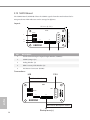
E3C224D4M-16RE
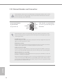
Onboard Headers and Connectors
N/A
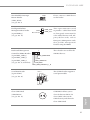
GND
SLOAD_MB
SCLOCK_MB
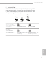
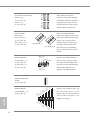
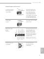
Serial General Purpose
Input/Output Header
(7-pin SGPIO1)
1
GND
SDATAOUT0_MB
SDATAJN0_MB
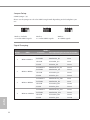
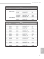
I2C Address
I2C Address
I2C Address
N/A
SGPIO Jumper
(8-pin J2)
his header support Serial
Link interface for onboard
SAS / SATA connections.
Please connect this header
with the SGPIO Connector
(LSI_SGPIO1) (see p.6, No.30)
on the motherboard via the
provided SGPIO 8PIN Cable.
his jumper allows the SGPIO
mode selection.
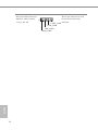
1
SCLOCK4_E15
SLOAD4_E16
SCLOCK2_E7
SLOAD2_E8
SDATAIN4_E13
SDATAOUT4_E14
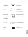
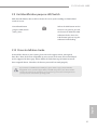
DC Power Connector
(4-pin PWR1)
SDATAOUT2_E6
SDATAIN2_E5
SDATAIN1_E1
SDATAOUT1_E2
3.3V
1
+5V
GND
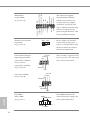
his 18-pin connector is used
for the front HDD status
indicators. Please connect
this header with the HDD
LED pins on the backplanes
via the provided SGIPOB to
Backplane Cable.
*For more information about the
backplanes, please refer to the user's
manual that comes with your chassis.
he 4-pin connectors
provide power to the
SGPIO board.
+12V
English
SLOAD3_E12
SLOAD1_E4
SDATAOUT3_E10
SCLOCK3_E11
GND
SDATAIN3_E9
HDD Activity LED
Header
(18-pin J3)
SCLOCK1_E3
GND
GND
GND
31