1
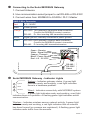
Connecting to the Serial MODBUS Gateway 1. Connect Antenna 2. Use communication select jumper to set RS-485 or RS-232C 3. Connect wires from MODBUS to SCADA / PLC / Master SMG 5-Wire Connector Red: 4.5 – 36VDC Black: Power ground Orange: RS-232C: TXD gateway’s transmitter data connection. Connect the MODBUS master’s receiver. RS-485: D+ Non-inverting 485 transmitter/receiver. White: Signal ground, internally connected to power ground. Green: RS-232C: RXD gateway’s receiver data connection. Connect the MODBUS master’s transmitter. RS-485: D- Inverting 485 transmitter/receiver. Reset Jumper Green - Receive White - Signal Ground Orange - Transmit Black - Power Ground Red - 4.5 - 36 VDC RS-485 / RS-232C Select Serial MODBUS Gateway - Indicator Lights System - Indicates gateway status. A green light indicates ready and working, a red light indicates L System there is a hardware problem. Wired L Serial MODBUS Gateway Wireless L Wireless Sensors Wired - for Indicates connectivity with MODBUS system. A green light indicates ready and working, a red light indicates there is a problem. A flashing green light indicates active communication. Wireless - Indicates wireless sensor network activity. A green light indicates ready and working, a red light indicates that no network has been formed (no sensors are registered). A flashing green light indicates radio traffic from the sensors. PAGE 3