1
MS-3000
Single Head Decoder
User's Manual
P/N 83-003001 REV. H
Information and specifications in this manual are subject to change without notice.
Copyright © 1998
by Microscan Systems, Inc.,
1201 S.W. 7th Street, Renton, Washington, U.S.A. 98055
(425) 226-5700 FAX: (425) 226-8682
All rights reserved. The information contained herein is proprietary and is provided solely for
the purpose of allowing customers to operate and/or service Microscan manufactured equipment and is not to be released, reproduced, or used for any other purpose without written permission of Microscan.
Throughout this manual, trademarked names might be used. Rather than put a trademark (™)
symbol in every occurrence of a trademarked name, we state herein that we are using the
names only in an editorial fashion, and to the benefit of the trademark owner, with no intention
of infringement.
Microscan Limited Warranty Statement and Exclusions
What is Covered?
Microscan Systems Inc. warrants to the original purchaser that products manufactured by it
will be free from defects in material and workmanship under normal use and service for a
period of one year from the date of shipment. This warranty is specifically limited to, at Microscan’s sole option, repair or replacement with a functionally equivalent unit and return without
charge for service or return freight.
What is Excluded?
Any products or parts that have been subject to misuse, neglect, accident, unauthorized
repair, improper installation, or abnormal conditions or operations. Any products or parts that
have been transferred by the original purchaser. Customer mis-adjustment of settings contrary to the procedure described in the Microscan owners manual. Upgrading software versions at customer request unless required to meet specifications in effect at the time of
purchase. Units returned and found to have no failure will be excluded. Claims for damage in
transit are to be directed to the freight carrier upon receipt.
THIS EXPRESS WARRANTY EXCLUDES ALL OTHER WARRANTIES, EXPRESS OR
IMPLIED, INCLUDING BUT NOT LIMITED TO, IMPLIED WARRANTIES OF MERCHANTABILITY AND FITNESS FOR PURPOSE. MICROSCAN SYSTEMS INC. SHALL NOT BE
LIABLE FOR ANY SPECIAL, INCIDENTAL, OR CONSEQUENTIAL DAMAGES, WHETHER
IN CONTRACT, TORT, OR OTHERWISE.
Some states do not allow the exclusion or limitation of incidental or consequential damages or
limitations on an implied warranty, so the above limitation or exclusion may not apply to you.
This warranty gives you specific legal rights, and you may also have other rights which may
vary from state to state.
The buyer acknowledges that he/she is not relying on the seller’s skill or judgment to select or
furnish goods suitable for any particular purpose and that there are no warranties that extend
beyond the description on the face hereof.
Before Requesting Service…
Please check the owners manual for proper setup and cabling procedures and any customer
settings for mis-adjustment for your particular application. Correcting these may save you a service call.
To receive Warranty Service…
Contact your nearest Microscan Service Center at the address shown below for a Return
Material Authorization (RMA) number before returning product. Receipt of an RMA number is
not an admission of warranty status. All product must be returned freight prepaid to the location issuing the RMA number before the expiration of the warranty period.
ii
MS-3000 Single Head Decoder User’s Manual
Table of Contents
List of Illustrations ................................................................................... v
List of Tables.......................................................................................... vi
About the MS-3000 Decoder ................................................................. vi
About This Manual ................................................................................. vi
Keystroke Entries.................................................................................. vii
Approvals .............................................................................................. vii
Warning and Caution Summary............................................................ vii
Safety Labels ........................................................................................viii
Chapter 1
Setup and Installation
Step 1 - Plan Scanning System ........................................................... 1-2
Step 2 - Attach Cabling ........................................................................ 1-3
Step 3 - Configure Decoder ............................................................... 1-10
Step 4 - Position Scan Head and Label ............................................. 1-10
Step 5 - Do Read Rate Test............................................................... 1-11
Step 6 - Install Decoder ..................................................................... 1-12
Ground and Shield Considerations .................................................... 1-14
Chapter 2
Menu Configuration
Communications Menu ........................................................................ 2-5
Operations Menu ............................................................................... 2-13
Code Types Menu.............................................................................. 2-22
User Outputs Menu............................................................................ 2-29
Raster Setup Menu ............................................................................ 2-33
Chapter 3
Serial Configuration
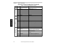
Summary of Serial Configuration Commands...................................... 3-2
Concatenating Serial Commands ........................................................ 3-4
Serial Command Status Request......................................................... 3-4
Loss of Communications...................................................................... 3-4
Trigger Filter Timing Value................................................................... 3-5
Communications Commands............................................................... 3-6
Operations Commands ...................................................................... 3-10
Code Types Commands .................................................................... 3-12
User Outputs Commands .................................................................. 3-14
Raster Setup Commands................................................................... 3-17
MS-3000 Single Head Decoder User’s Manual
iii
Chapter 4
Profile Card Configuration
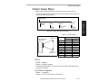
Summary of MS-3000 Modes.............................................................. 4-2
Operating Instructions ......................................................................... 4-3
General Settings.................................................................................. 4-4
Communications Settings.................................................................... 4-6
Operations Settings ............................................................................. 4-8
Code Types Settings ......................................................................... 4-11
User Outputs Settings ....................................................................... 4-11
Chapter 5
Operational Commands
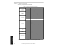
Summary of Operational Commands .................................................. 5-2
Program Management Commands ..................................................... 5-3
Device Control Commands.................................................................. 5-3
Code Type Commands........................................................................ 5-4
Counter Commands ............................................................................ 5-4
Test Commands .................................................................................. 5-5
Status Commands ............................................................................... 5-5
Master Label Commands .................................................................... 5-5
Appendices
Appendix A — Decoder Specifications............................................... A-2
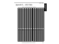
Appendix B — ASCII Table ................................................................ A-3
Appendix C — Defaulting the Decoder................................................ A-4
Appendix D — Troubleshooting........................................................... A-6
Appendix E — Interfacing with the MS-90 Scan Head ....................... A-9
Appendix F — Bar Code Symbology................................................. A-11
Appendix G — Interface Standards................................................... A-12
Appendix H — Auxiliary Monitor ........................................................ A-13
Appendix I — Multidrop Communications ...............................................A-17
Appendix J — Glossary of Terms...................................................... A-21
iv
MS-3000 Single Head Decoder User’s Manual
List of Illustrations
Figure 1-1 System Diagram ....................................................................... 1-2
Figure 1-2 Front Panel ............................................................................... 1-3
Figure 1-3 Trigger Connector Socket ......................................................... 1-4
Figure 1-4 Trigger Connector Wiring Diagram (untriggered) ..................... 1-5
Figure 1-5 Decoder to Scan Head ............................................................. 1-5
Figure 1-6 Rear Panel of MS-3000 Decoder .............................................. 1-6
Figure 1-7 Power Connector Socket .......................................................... 1-6
Figure 1-8 LAN Connector ......................................................................... 1-7
Figure 1-9 Host Connector ......................................................................... 1-9
Figure 1-10 DTE and DCE Host Connections ............................................ 1-9
Figure 1-11 Monitor Connector .................................................................. 1-9
Figure 1-12 Bottom Mounting Diagram (not full size) ............................... 1-12
Figure 1-13 Mounting Diagram (without housing, not full size) ................ 1-13
Figure 1-14 Grounding Diagram, Decoder-Host ...................................... 1-14
Figure 2-1 Configuration Program - Main Menu ......................................... 2-2
Figure 2-2 Communications Menu Structure ............................................. 2-5
Figure 2-3 Operations Menu Structure ..................................................... 2-13
Figure 2-4 External Level Trigger Signals ................................................ 2-15
Figure 2-5 External Edge Trigger Signals ................................................ 2-15
Figure 2-6 Match Code Logic Diagram .................................................... 2-20
Figure 2-7 Code Types Menu Structure ................................................... 2-22
Figure 2-8 User Outputs Menu Structure ................................................. 2-29
Figure 2-9 Raster Setup Menu Structure ................................................. 2-33
Figure 2-10 Raster Sweep Arc ................................................................. 2-33
Figure 4-1 Profile Card ............................................................................... 4-3
Figure A-1 MS-2000 ...................................................................................A-2
Figure A-2 MS-3000 ...................................................................................A-2
Figure A-3 Profile Card Default Setting ......................................................A-4
Figure A-4 Host Connector Default Pins ....................................................A-5
Figure A-5 MS-90 User Outputs Menu (with Label Speed Option) ............A-9
Figure A-6 Typical Multidrop Network ......................................................A-17
Figure A-7 Polling Sequence ...................................................................A-18
Figure A-8 Select Sequence ....................................................................A-19
MS-3000 Single Head Decoder User’s Manual
v
List of Tables
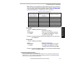
Table 1-1 Cable Distances ........................................................................ 1-3
Table 1-2 Trigger Connector Pin Assignments .......................................... 1-4
Table 1-3 Power Connector Pin Assignments ........................................... 1-6
Table 1-4 LAN Connector Pin Assignments .............................................. 1-7
Table 1-5 Host Connector Pin Assignments .............................................. 1-8
Table 1-6 Monitor Connector Pin Assignments ......................................... 1-9
Table 2-1 Raster Settings ........................................................................ 2-33
Table 3-1 Summary of Serial Configuration Commands ........................... 3-2
Table 3-2 Protocol Commands .................................................................. 3-7
Table 4-1 Profile Card Mode Descriptions ................................................. 4-2
Table 4-2 Calculating Binary Conversion ................................................ 4-13
Table 5-1 Summary of Operational Commands ........................................ 5-2
Table A-1 Status Lights ............................................................................. A-2
Table A-2 ASCII Table with Control Characters ........................................ A-3
Table A-3 Troubleshooting Table .............................................................. A-6
Table A-4 Label Speeds for Code 39 in Inches per Second .................... A-10
Table A-5 Label Speeds for Code 128 in Inches per Second .................. A-10
Table A-6 Multidrop Address Characters ................................................. A-20
vi
MS-3000 Single Head Decoder User’s Manual
About the MS-3000 Decoder
The MS-3000 single head decoder, companion to Microscan’s MS-520 and
MS-1200 scan heads, is designed to accept high speed bar code data from
a scan head, translate that data into alphanumeric characters, and send
that data to a host or other terminal.
MS-3000 Single Head Decoder User’s Manual
vii
About This Manual
This manual provides complete information on setting up and installing the
MS-3000 decoder.
Chapter 1 provides overall step-by-step instructions for setting up and
installing the MS-3000 decoder with specific “go to” references to other
chapters and appendices.
Chapter 2 provides instructions for configuring the MS-3000 decoder by
menu.
Chapter 3 provides instructions for configuring the MS-3000 decoder by
serial command.
Chapter 4 describes serial operational commands that can be used by the
host.
For specifications, see appendix A. The appendices also include reference
tables, as well as other useful information relating to bar coding and the
MS-3000 decoder.
viii
MS-3000 Single Head Decoder User’s Manual
Keystroke Entries
Keystrokes to be entered from your terminal are highlighted in bold, as in <D>, including a < left angle bracket symbol (unless redefined by Command Start Character
command) and followed by a > right angle bracket symbol.
MS-3000 Single Head Decoder User’s Manual
ix
Approvals
• UL (Underwriters Laboratories, Inc.)
• CSA (Canadian Standards Association)
• TüV (Technischer überwachungs-Verein) European models must use a
similarly rated Class 1 or Class 2 power supply that is certified with the
standard for Safety EN 60950:1992 + A2:1993 or A3:1995.
• FCC (Federal Communication Commission)
• This Class A digital apparatus meets all requirements of the Canadian
Interference-Causing Equipment Regulations.
Cet Appareil numerique de la classe A respecte toutes les exigences du
Reglement sur le material broilleur du Canada.
x
MS-3000 Single Head Decoder User’s Manual
Warning and Caution Summary
Caution: There are no user serviceable parts in the MS-3000 decoder.
Opening the decoder voids the Microscan Systems warranty.
Note: The MS-520 and MS-1200 scan heads are designed to be connected to the MS-2000 and 3000 decoders. When installed, power for
the scan head is provided by the decoder.
Caution: This equipment has been tested and found to comply with the
limits for a Class B digital device, pursuant to part 15 of the FCC Rules.
These limits are designed to provide reasonable protection against harmful
interference when the equipment is operated in a commercial environment. This equipment generates, uses, and can radiate radio frequency
energy, and, if not installed and used in accordance with the instruction
manual, may cause harmful interference to radio communications. Operation of this equipment in a residential area is likely to cause interference in
which case the user will be required to correct the interference at his or her
own expense.
Note: For connection to a listed direct plug-in power unit marked Class 2
and rated at +12 VDC regulated @ 40 mA maximum, –12 VDC regulated
@ 40 mA maximum, +5 VDC regulated @ 300 mA maximum.
MS-3000 Single Head Decoder User’s Manual
xi
Safety Labels
The following labels are found on the bottom of the MS-3000:
T H I S E Q UI P M E N T H A S B E E N T E S T E D W I T H C L A S S A
CO M P U T ING
D E V I C E S , A N D H A S B E E N FO U N D T O C O M P L Y W I T H P A R T 1 5 O F FC C
M A Y C A U S E U N A C C E P T A B L E IN T E R FE R E N C E T O R A D I O A N D T V
R U L E S . S E E IN S T R U C T I O N M A N U A L . O P E R A T I O N IN A R E S I D E N T I A L A R E A
1 2 0 1 S . W . 7 th S t.
R e n to n , W A 9 8 0 5 5
R E C E P T I O N R E Q U I R IN G T H E O P E R A T O R T O T A K E W H A T E V E R S T E P S A R E
U.S . P A T E NT NO .: 4,8 55,58 1
N E C E S S A R Y T O C O R R E C T T H E I N T E R FE R E N C E .
P O WE R:
LIS T E D
R
UL 19 50
4K 6 8
SER IAL NU MBE R
1 1 -1 0 0 0 1 8 -0 2
FIS NO .
M A D E I N U .S . A .
MANU FAC T UR E D
CAUTION: The6-32mountingscrews
should not extend morethan0.12in.
(3mm) intothemounting holes.
xii
MS-3000 Single Head Decoder User’s Manual
+1 2V ,
40 m A
- 1 2V ,
40 m A
+ 5V ,
3 00 m A
1
1–Setup and Inst.
Chapter
1
Setup and
Installation
Chapter Contents
Step 1 - Plan Scanning System............................................................1-2
Step 2 - Attach Cabling ........................................................................1-3
Step 3 - Configure Decoder................................................................1-10
Step 4 - Position Scan Head and Label .............................................1-10
Step 5 - Do Read Rate Test ...............................................................1-11
Step 6 - Install Decoder......................................................................1-12
Ground and Shield Considerations ....................................................1-14
This chapter provides step-by-step instructions for setting up and installing the 3000 single head decoder.
Note: Bar code labels should meet minimum ANSI (American National
Standards Institute) standards as specified in ANSI Bar Code Print Quality
Guideline, X3.182-1990.
MS-3000 Single Head Decoder User’s Manual
1-1
1–Setup and Inst.
Chapter 1
Setup and Installation
1 Plan Scanning System
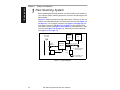
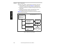
Before installing the MS-3000 decoder you should sketch out a diagram of
your scanning system, showing equipment, connector and cable types, and
cable lengths.
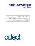
Figure 1-1 shows a possible scanning system setup. There are six I/O connectors on the MS-3000 decoder: the 25-pin host connector (see figure 1-9
on page 1-9), a 6--pin trigger connector (see figure 1-4 on page 1-5), the
5-pin power connector (see figure 1-7 on page 1-6), the modular RJ-45
scan head connector (see figure 1-5 on page 1-5), the modular RJ-11 LAN
connector (see figure 1-8 on page 1-7), and the 9-pin monitor connector
(see figure 1-11 on page 1-9).
Bar-coded
item flow
Optional
monitor
Object
Detector
MS-3000
Deco der
8-pin cable
To optional multidrop
concentrator
Power
pack
Scan Head
Figure 1-1 System Diagram
1-2
Host
MS-3000 Single Head Decoder User’s Manual
To 120/240 VAC
pow er supply
Attach Cabling
1–Setup and Inst.
2 Attach Cabling
Under ideal conditions, maximum cable lengths can match
the distances shown in table
1-1. However, since cable
lengths and sizes are dictated
by local conditions such as
wire size, wire shape (flat or
round), shielding, grounding,
extraneous signal noise, etc.,
maximum cable distances will
vary.
Table 1-1 Cable Distances
Maximum
Distance
Cabling
RS-232 Decoder to Host 50 ft. (15.2 m)
RS-422 Decoder to Host 4000 ft. (1219 m)
Decoder to Scan Head
15 ft. (4.57 m)
RS-485 Multidrop Trunk
4000 ft. (1219 m)
RS-485 Multidrop Drop
10 ft. (3 m)
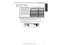
Front Panel Connectors
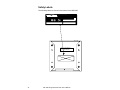
The MS-3000 decoder has six I/O connectors. On the front panel
(figure 1-2) there are the following two connectors:
a. Trigger (Microscan or other object detector) (6-pin DIN socket)
b. Scan head (modular RJ-45)
PW R
TR I G
S C AN
IN D 2
IN D 1
Figure 1-2 Front Panel
MS-3000 Single Head Decoder User’s Manual
1-3
1–Setup and Inst.
Chapter 1
Setup and Installation
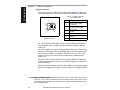
Trigger Connector
The trigger connector (TRIG) is a 6-pin DIN socket (figure 1-3) that mates
with a 240 degree 6-pin DIN plug. Pin assignments are shown in table 1-2.
Table 1-2 Trigger Connector
Pin Assignments
6
1
Pin
5
TRIG
4
3
2
Figure 1-3 Trigger
Connector Socket
Function
1
Trigger Input +3 VDC
to + 24 VDC
2
TTL Relay driver output
signal 5 VDC
3
+5 VDC
4
+12 VDC
5
Ground
6
Not used
Pin 1 is the input from the object detector. When operating the decoder in
external trigger mode, a toggle at this pin causes the decoder to begin a
read cycle.
Pin 2 of the trigger connector is a programmable relay driver. The MS-3000
software can be programmed to set this pin high or low upon a good read, a
no read, a good match, or a mismatch. This pin can source or sink 4 mA
(maximum) and can be used to drive a small relay to operate an alarm,
diverter, etc.
Microscan offers an optical object detector (P/N 99-440001-03) that plugs
directly into this connector and a user-customized trigger port connector (P/
N 20-600090-02). 1
Figure 1-4 shows examples of positive and negative external trigger inputs
that could be applied to the trigger connector. (Shown in untriggered state.)
1. Trigger sources other than the Microscan object detector can be used. Mechanical switches,
relays, etc.—which tend to be slow and bouncy and produce multiple trigger signals—are not
recommended unless equipped with optical sensors or filtered transitions (optical, Hall effect,
or DC solid state relays).
1-4
MS-3000 Single Head Decoder User’s Manual
Attach Cabling
Negative Trigger
J2
+0 VDC to +24 VDC
1–Setup and Inst.
Positive Trigger
J2
1
Trigger input
2
Aux. relay driver
3
+5 VD C
4
+12 VD C
+0 VDC to +24 VDC
1
Trigger input
2
Aux. relay driver
3
+5 VDC
4
+12 VDC
5
Ground
6
Not used
N.C.
N.O.
Solid
state
switching
device
5
Ground
6
Not used
Solid
state
switching
device
Decoder
Decoder
Figure 1-4 Trigger Connector Wiring Diagram (untriggered)
Scan Head Connector
To prevent voltage loss, cables between decoder and scan head should not
exceed 15 feet (4.57 m) unless wire sizes exceed the minimum 26 AWG.
Figure 1-5 shows a MS-3000 decoder connected to a Microscan MS-500
scan head.
MS-520 Scan Head
MS-3000 Decoder
PW R
TRIG
SC AN
IND2
IND1
Figure 1-5 Decoder to Scan Head
MS-3000 Single Head Decoder User’s Manual
1-5
1–Setup and Inst.
Chapter 1
Setup and Installation
Back Panel Connectors
On the rear panel (figure 1-6) there are the following four connectors:
a. Power (5-pin DIN socket)
b. LAN (modular RJ-11)
c. Host (25-pin D-subminiature socket)
d. Monitor (9-pin D-subminiature socket)
HOST
POWER
MONITOR
LAN
Figure 1-6 Rear Panel of MS-3000 Decoder
Power Connector
The power connector (figure 1-7) has a 5-pin DIN socket with pin assignments shown in table 1-3.
You may also supply the required DC voltages yourself. A mating connector
(Switchcraft #05BL5M plug) is required.
Caution: Switching power supplies for Microscan equipment with a switching
noise of 20 mV or greater with ±12 VDC are not recommended due to excessive ripple characteristics.
Table 1-3 Power Connector
Pin Assignments
1
Pin
3
5
POWER
2
4
Figure 1-7 Power
Connector Socket
1-6
Function
1
DC Ground
2
Chassis Ground
3
+5 VDC
4
–12 VDC
5
+12 VDC
MS-3000 Single Head Decoder User’s Manual
Attach Cabling
The Local Area Network (LAN) connector allows the MS-3000 decoder to
communicate with a multidrop concentrator via a 4-wire cable (preferably
shielded) with a 6-pin, 6-wire, RJ-11 type connector. Pin assignments are as
shown in table 1-4. The LAN connector is used when a MS-3000 decoder is
configured for RS-485 multidrop communications.
1
Table 1-4 LAN Connector
Pin Assignments
6
Pin
Figure 1-8 LAN Connector
Function
1
Ground
2
Receive Data (+)
3
Receive Data (–)
4
Transmit Data (+)
5
Transmit Data (–)
For proper operation of RS-485 multidrop communications, the main cable
should not exceed 4000 feet, with each drop no more than 10 feet. The
Microscan MS-5000 multidrop concentrator can support up to 50 decoders
or other multidrop devices on one RS-485 line. Note that the last device
must be terminated correctly. RS-485 pinouts are also available at the host
connector.
Host Connector
The host connector (figure 1-9 on page 1-9), a 25-pin D-subminiature
socket, allows the decoder to be connected to a host, a concentrator, or
other communications device such as a PLC (programmable logic controller), a monitor, a PC, a relay, a diverter, an alarm, etc.
Note: All Microscan products are configured as DTE at the host connector
when in RS-232 operation.
Caution: Do not use a host cable with more wires connected than are required
for the application. The host connector of the decoder has many outputs that
could cause damage or interfere with normal operation if connected and improperly used.
MS-3000 Single Head Decoder User’s Manual
1-7
1–Setup and Inst.
LAN Connector
1–Setup and Inst.
Chapter 1
Setup and Installation
Table 1-5 Host Connector Pin Assignmentsa
Pin
Function
1
2
Chassis ground
Transmit data
3
Receive data
4
Request-to-send
5
Clear-to-send
6
7
8
9
10
TTL 5V signal
Signal Ground
TTL 5V signal
+5 VDC
Trigger input
11
Default (reset)
12
13
14
16
19
Aux Input
RXD +
TXD –
RXD –
TXD +
20
+12 VDC
21
22
23
24
25
Profile Card Input
Signal Ground
–12 VDC
+12 VDC
Match Code
Comment
connected to dc ground
+12v data output from the decoder
±12v signal indicating data from the host to the
decoder
±12v signal asserted high by the decoder when it
has data to send to the host
±12v signal asserted low by the host to stop the
decoder from sending data to it (data transmission
will resume when the signal is asserted high.)
indicates a good read
connected to chassis ground
indicates a noread
auxiliary supply
+0 VDC to +24 VDC
resets decoder to default
configuration
(future use)
RS-422/485
RS-422/485
RS-422/485
RS-422/485
data terminal ready (asserted high on power-up to
indicate decoder is on)
next label read as master label, if enabled
a. The default communications mode does not support pin 4 (RTS). If RTS is not required by
the host port, pin 4 should not be wired as the results will be unpredictable.
A good read will cause a 5V signal (high or low) to be output to pin 6. A
noread will cause a 5V signal (high or low) to be output to pin 8.
Caution: There must be ±12V present before the decoder will transmit data to
the host. However, the decoder can receive commands without the presence
of either voltage.
1-8
MS-3000 Single Head Decoder User’s Manual
Attach Cabling
1–Setup and Inst.
DB-25 DTE to DB-25 DTE Con nection
Decoder
1
HOST
Host
Transmit
2
2
Transmit
Receive
3
3
Receive
Signal Grnd
7
7
Signal Grnd
DB-25 DTE to DE-9 DCE Connection
25
Figure 1-9 Host Connector
Decoder
Host
Transmit
2
2
Receive
3
3
Transmit
Signal Grnd
7
5
Signal Grnd
Receive
Figure 1-10 DTE and DCE Host
Connections
Monitor Connector
The monitor connector (auxiliary terminal) connects the decoder to an auxiliary monitor via a 9-pin D-subminiature socket and cable. Table 1-6 shows
auxiliary terminal pin assignments. Communication at this connector is
RS-232 only.
1
MONITOR
9
Table 1-6 Monitor Connector
Pin Assignments
Pin
Function
2
Receive Data (in)
3
Transmit Data (out)
5
Signal Ground
Figure 1-11 Monitor Connector
MS-3000 Single Head Decoder User’s Manual
1-9
1–Setup and Inst.
Chapter 1
Setup and Installation
3 Configure Decoder
Settings for Communications, Operations, Code Types, and User Outputs
and Raster Setup are stored in non-volatile memory and can be configured
by menu, serial command, or profile card commands.
For explanations of configuration settings, see Chapter 2, “Menu Configuration.”
To establish communications you will need to match the host’s or auxiliary
terminal’s communication settings with your decoder’s settings (see Communications Menu” on page 2-5). Also make certain that the code type
enabled in the decoder matches that of the label being used (see Code
Types Menu” on page 2-22).
Hint: Sending the <P> command will allow your scan head to read all of the
listed code types.
Communicating with and ASCII Terminal
The MS-3000 decoder communicates in full duplex, terminal mode with no
handshake. It also recognizes carriage returns and line feeds.
The host or ASCII terminal must match the following default settings before any
communication can take place: 9600 Baud Rate, Seven Data Bits, Even Parity,
and One Stop Bit.
A PC or Macintosh computer can be used as a dumb terminal if connected as
shown in table 1-5 on page 1-8 and running a communications program set to
the above defaults. See your computer user’s manual for communication’s port
pinouts.
4 Position Scan Head and Label
Before testing, you will need to position the scan head and label in a manner that matches as nearly as possible the actual conditions of your application. Consult your scan head user’s manual for important setup
specifications.
1-10
MS-3000 Single Head Decoder User’s Manual
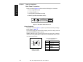
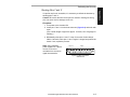
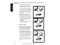
Do Read Rate Test
This test calculates the percentage of scans decoded. It is useful during
setup procedures to help optimize scan head-to-label orientation.
a. Place the label used in your application in front of the scan head and
within the desired read range.
Note: Ensure that the label being scanned is of a code type enabled in the
decoder’s software.
Hint: Read rates are easier to read on the screen if Postamble is enabled.
b. Select from the ESP Utilities menu or send a <C> command to the
decoder to start testing (see the “Enter Read Rate Test” command on
page 5-5).
A percentage number from 0 to 100
will be displayed on the monitor in
the read rate test indicating the ratio
of good reads per total number of
scans.
c. Find the correct read rate area by
moving the label in and out and right
and left while observing read rate on
the monitor.
Read Rate
Percentage
Label Data
Avoid the specular reflection area (see scan head user’s manual).
d. Record the range area measurements and file the test results for
future reference.
If the results are not satisfactory, reposition or re-configure the
decoder or choose a different narrow-bar-width label size.
e. Select from the ESP Utilities menu or send a <J> command to the
decoder when testing is complete (see the “Exit Read Rate Test” command on page 5-5).
MS-3000 Single Head Decoder User’s Manual
1-11
1–Setup and Inst.
5 Do Read Rate Test
1–Setup and Inst.
Chapter 1
Setup and Installation
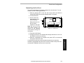
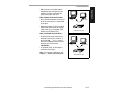
6 Install Decoder
The MS-3000 decoder can be mounted temporarily using the four rubber
pads, or permanently, as follows:
a. Position the decoder in a dry place.
b. Before mounting, ensure that there is at least a 3 inch (76.2 mm) clearance at the rear and front of the decoder for the connectors and cables
being used.
c. Use the measurements provided in figure 1-12 to locate centers of
mounting holes and drill four 5/32 inch or four 4 mm holes.
d. Secure decoder with four 6-32 screws of the appropriate length.
Caution: Make certain that mounting screws do not penetrate into the
decoder case more than .175 in. (4.4 mm) or damage to the decoder could
result.
Measurements in inches (millimeters)
1.85"
(46.99)
6.2"
(157.48)
Fro nt
Optional foot pads
(4 places)
2.5"
(63.5)
6/32 threads
(4 places)
0.5"
(12.7)
5.6"
(142.24)
Figure 1-12 Bottom Mounting Diagram (not full size)
1-12
MS-3000 Single Head Decoder User’s Manual
Install Decoder
1–Setup and Inst.
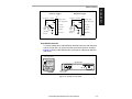
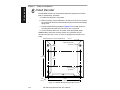
If the unit does not have housing, use the measurements provided in
figure 1-13 to locate the centers of the mounting holes.
Measuremen ts i n inc hes (mill im et ers)
Front
1.0"
(25.4)
0.160" (4.06)
Dia. (4 places)
5.8" (147.32)
3.8" (96.52)
4.5" (114.30)
5.2" (132.08)
5.8" (147.32)
0.030" (7.62)
Figure 1-13 Mounting Diagram (without housing, not full size)
MS-3000 Single Head Decoder User’s Manual
1-13
1–Setup and Inst.
Chapter 1
Setup and Installation
Ground and Shield Considerations
Proper grounding is necessary for operator safety, noise reduction, and the
protection of equipment from voltage transients. Buildings–including any
steelwork, all circuits, and all junction boxes–must be grounded directly to
an earth ground in compliance with local and national electrical codes.
RS-232 signals have a common signal ground (pin 7 of the 25-pin connector). Pin 7 is normally connected to pin 1 (chassis ground) in the decoder;
however, under certain conditions (e.g., when potential differences exist
between power outlet grounds) signal and chassis grounds can be isolated
from each other inside the decoder by Microscan technicians.
Any data line, as necessary, can be shielded. If shielding is used, isolate it
from the decoder and ground only to the host earth ground.
Noise Interference
Noise interference can be minimized if cabling subject to
noise interference is twisted
HOST
and/or shielded or encased in
Shielding
grounded conduit, and the
Communications
conduit or shielding (“drain”
Cable
line) is grounded only to earth
EarthGround
ground at the host, as shown in
figure 1-14. You might need to
Decoder
examine and if necessary cut
the shielding connection at or
Figure 1-14 Grounding Diagram, Decoder-Host
near the concentrator cable
connector.
Ground Loops
Ground loops, signal degradation due to different ground potentials in communicating devices, can be eliminated or minimized by ensuring that the
host, concentrator, and their power supplies are connected to a common
earth ground.
1-14
MS-3000 Single Head Decoder User’s Manual
Chapter
2
Menu
Configuration
Communications Menu ........................................................................ 2-5
Operations Menu ............................................................................... 2-13
Code Types Menu.............................................................................. 2-22
User Outputs Menu............................................................................ 2-29
Raster Setup Menu ............................................................................ 2-33
This chapter describes how to configure the MS-3000 decoder with on
screen menu commands from a host or auxiliary terminal.
All keystrokes are in bold typeface.
Default parameters in the menu structures are also in bold typeface.
All of these parameters, with the exception of Full Screens, can also be
changed by serial commands (see Chapter 3, “Serial Configuration”).
In addition, most of these configuration parameters can also be changed
with a Microscan profile card (P/N 99-500011-01), obtainable from your
Microscan representative (see Chapter 4, “Profile Card Configuration”).
Communicating with an ASCII Terminal
The MS-3000 decoder communicates in full duplex, terminal mode with no
handshake. It also recognizes carriage returns and line feeds.
The host or ASCII terminal with must match the following default settings
before any communication can take place: 9600 Baud Rate, Seven Data
Bits, Even Parity, and One Stop Bit.
MS-3000 Single Head Decoder User’s Manual
2-1
2–Menu Config.
Chapter Contents
Chapter 2
Menu Configuration
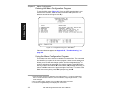
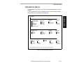
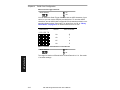
Entering the Menu Configuration Program
To see the Main menu (figure 2-1), from an ASCII terminal that is connected to the decoder, send the serial command <D> (enter the < >
brackets as well as the upper case D).1
2–Menu Config.
xx
Figure 2-1 Configuration Program - Main Menu2
If the menu does not appear, see Appendix D, “Troubleshooting,” on
page A-6.
Using the Menu Configuration Program
The bottom line on the screen is called the command line. The command
line identifies your place in the menu program, shows current status and
allows you to review and change options. Use the designated keys3 to
scroll to and select the parameter you wish to change; press SP (space
bar key) or N to scroll ahead, B to scroll back, CR (carriage return key) to
select, and M to return to the previous higher level menu. To return to the
Main menu at any time, press ESC (escape key) and M.
1. Command start character by default is a left angle bracket, <. It may be redefined by
menu or serial command. However, the end character, a right angle bracket, >, cannot be changed.
2. Item 5, Raster Setup, applies only to the MS-1280 raster scan head.
3. The menu navigational keys are displayed in each menu.
2-2
MS-3000 Single Head Decoder User’s Manual
For example, to enable LRC (see figure 2-2, “Communications Menu
Structure,” on page 2-5 and “Longitudinal Redundancy Check” on
page 2-10), you would use the following command line path:
From the Main menu, press
CR at the Communications
prompt (this is the first prompt
displayed in the Menu Configuration Program) to access the
Communications menu.
Communications —> Host Protocol
Communications —> Host Port
Communications —> Aux Port
Since LRC is a subtopic of
Host Protocol, press CR to
access the Host Protocol
parameters.
Host Protocol —> Protocol
Host Protocol —> Preamble = ^M
Host Protocol —> Preamble = Disabled
Host Protocol —> Postamble = ^M^J
Host Protocol —> Postamble = Disabled
Host Protocol —> LRC
= Disabled
Host Protocol —> Response Timeout in 1ms incs = 12
Host Protocol —> Intercharacter Delay in 1ms incs = 0
Host Protocol —> LRC
Host Protocol —> LRC
= Disabled
= Enabled
Protocol is the first parameter
under Host Protocol. Press SP
until you reach LRC, then
press CR.
To enable LRC, press CR, SP,
and CR.
To view LRC’s new status in the menu, press M to refresh the screen. To
return to the Main menu, press M again. You can make additional changes
within another menu before exiting the program. Simply follow the same
method of scrolling to and selecting each main topic, then its subtopics, until
you reach the parameter you want to change. Remember, to return to the
Main menu at any time, press ESC (escape key) and M.
Some parameters are user defined, in which case they prompt you with an
arrow for data, such as:
At the prompt, redefine the parameter within the allowable range, and press
CR to enable.
MS-3000 Single Head Decoder User’s Manual
2-3
2–Menu Config.
Main —> Communications
Main —> Operations
Main —> Code Types
Main —> User Outputs
Main —> Raster Setup
Chapter 2
Menu Configuration
Saving Menu Changes
Press ESC (escape key) to see the following on the command line:
Press M to return to the Main menu, or press E to exit the Menu Configuration program. If E is pressed, the following question will appear:
2–Menu Config.
Press N to exit without saving changes, or press Y to retain the current settings to non-volatile RAM for power up. If Y is selected, a beep will indicate
the save has been carried out.
Loss of Communications
Defaulting might be necessary if communications between the decoder and
another device are interrupted or if using incompatible equipment (for
example, a terminal is set to communicate at 9600 baud, but the decoder is
configured at 38.4K baud). Communication can also be lost if an address
has been assigned to the decoder.
To reset parameters to default values, see Appendix C, “Defaulting the
Decoder,” on page A-4.
Defining Special Characters
To define any control character from the ASCII table: Press SP once, then
enter the control character by holding down the control key and simultaneously pressing the desired character. For example to define a line feed,
press SP, then Control and J simultaneously. It is displayed as ^J on the
command line and as <LF> in the menu when the screen is refreshed.
To define CR as a character: Press SP, then CR. It is displayed as ^M on
the command line and as <CR> in the menu when the screen is refreshed.
To define a space as a character: Press SP twice. It is displayed as a blank
space in the menu when the screen is refreshed. While it appears that nothing has been assigned, the hex value 20 will be sent during data transmission.
To select NUL as the character: Press SP, then a 0 (zero). It is displayed as
<NUL> in the menu when the screen is refreshed.
2-4
MS-3000 Single Head Decoder User’s Manual
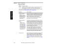
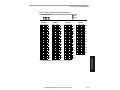
Communications Menu
Communications Menu
The Communications menu allows you to set the communication protocols
between the decoder and the host.
Communications
–
Bold text represents default settings.
Host Protocol
Protocol
–
–
–
–
–
Preamble
–
User Defined
–
User Defined Multidrop
–
RES
– RES
–
–
–
Postamble
Disabled
Enabled
– Address = ^A – REQ – EOT
– Address = ^A – REQ – EOT
LRC
–
Preamble
Point-to-Point
– ^M
Point-to-Point
– User
w/RTS/CTS
Definable
(ASCII char.)
Point-to-Point
w/XON/XOFF
Point-to-Point
w/RTS/CTS &
XON/XOFF
Polling Mode D
Multidrop
– Address = 1
– User Definable (1 to 50)
–
–
–
–
–
–
Disabled
Enabled
– STX
– ETX
– ACK – NAK
– STX
– ETX
– ACK – NAK
Interchar Delay
Response Timeout
Disabled
Enabled
Postamble
^M ^J
User
Definable
(ASCII char.)
12
User Definable (0 to 65,000)
–
–
0
User Definable (0 to 255)
Host Port
Baud Rate
–
–
–
–
9600
19.2K
38.4K
600
Stop Bits
Parity
– 1200
–
– 2400
–
– 4800
–
–
Even
Odd
None
–
One
Two
Data Bits
–
–
Seven
Eight
RS-422
–
–
Disabled
Enabled
Aux Port
Aux Mode
–
–
–
–
Disabled
Transparent
Half Duplex
Full Duplex
Baud Rate
–
–
–
–
9600
19.2K
38.4K
600
Parity
– 1200
–
– 2400
–
– 4800
–
Stop Bits
Even
Odd
None
–
–
One
Two
Data Bits
–
–
Seven
Eight
Figure 2-2 Communications Menu Structure
MS-3000 Single Head Decoder User’s Manual
2-5
2–Menu Config.
–
Chapter 2
Menu Configuration
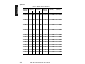
There are three subtopics in this menu: Host Protocol, Host Port, and Aux Port.
To help visualize the menu’s organization and to locate the page number
where each topic is described, see figure 2-2, “Communications Menu
Structure,” on page 2-5.
Note: Changes in Communications parameters or assigning an address to the
decoder can cause loss of communications with the configuration terminal when
you exit the menu program (whether or not changes are saved for power-on).
2–Menu Config.
Host Protocol Parameters
Protocol
Default: Point-to-Point
Options: Point-to-Point, Point-to-Point with RTS and CTS, Point-to-Point
with XON/XOFF, Point-to-Point with RTS/CTS and XON/XOFF,
Polling Mode D, Multidrop, User Defined, User Defined Multidrop
Protocols define the sequence and format in which information is transferred
between devices. Generally there are two basic protocol modes: unpolled
and polled. In unpolled mode (all of the Point-to-Point protocols), a device
sends information without being asked for by the host. In polled mode (Multidrop, Polling Mode D, and User Defined Multidrop), a device has an address
and waits for a request from the host before sending data.
Note: User Defined and User Defined Multidrop have more options available to
them. Selection instructions for these protocols are provided under each topic.
Selecting:
2-6
Has this effect:
Point-to-Point
Has no address and sends data to the host
(RS-232) whenever it is available and without any
request or handshake from the host.
Point-to-Point with
RTS/CTS (Request-toSend/Clear-to-Send)
Used only with RS-232. This is a simple handshaking
protocol that allows a device to initiate data transfers
to the host with an RTS (request-to-send)
transmission. The host, when ready, responds with a
CTS (clear-to-send) and the data is transmitted. RTS
and CTS signals are transmitted over two dedicated
wires (pins 4 and 5) as defined in the RS-232
standard.
MS-3000 Single Head Decoder User’s Manual
Communications Menu
Selecting:
Has this effect:
Used only with RS-232 or RS-422. This selection
enables the host to send a single byte
transmission command of start (XON) or stop
(XOFF). If an XOFF has been received from the
host, data will not be sent to the host until the
host sends an XON. During the XOFF phase, the
host is free to carry on other chores and accept
data from other devices.
Point-to-Point
with RTS/CTS
and XON/XOFF
Used only with RS-232. It is a combination of Pointto-Point with RTS/CTS and Point-to-Point with
XON/XOFF.
Polling Mode D
Like Point-to-Point, Polling Mode D requires a
separate connection to the host but unlike Point-toPoint, it requires the device to have an address and
to wait for a poll from the host before sending data.
When in Polling Mode D, an address 1 is
automatically displayed on the configuration
screen. However, during transmission, a 1C hex
poll address (FS) and a 1D hex select address
(GS) are substituted for the 1.
Multidropa
Note: Decoders intended to link up to a
MS-5000 multidrop
concentrator can
only be configured in
standard Multidrop
protocol.
Hint: Attach a tag to
each decoder to
identify its multidrop
address.
Similar to Polling Mode D except that a unique poll
address and select address are required for each
multidrop device, and only one host port connection
is needed for up to 50 devices. (For Multidrop poll
and select characters, see Table A-6, “Multidrop
Address Characters,” on page A-20.)
Requires a concentrator or controller using RS-485
communications. When Multidrop is selected, the
protocol characters for RES, REQ, etc. are
assigned automatically. (See “Appendix I —
Multidrop Communications” on page A-17 for
poll and select sequences.)
MS-3000 Single Head Decoder User’s Manual
2-7
2–Menu Config.
Point-to-Point
with XON/XOFF
(Transmitter On/Off)
Chapter 2
Menu Configuration
Selecting:
Has this effect:
Used only with RS-232 or RS-422. ASCII
characters can be assigned as an address and as
protocol commands (RES, REQ, EOT, STX, ETX,
ACK, and NAK). User Defined is necessary when a
new protocol must be defined to match a specific
NOTE:
Note: AAspecific
specificASCII
host protocol. When User Defined is selected, the
ASCII
character
character
must not
must
be
displayed protocol commands match those of the
not
assigned
be assigned
more than
more
previously selected protocol. User Defined is
than
once.
once.
considered to be in a polled mode only if an address
has been assigned. The address can be any ASCII
character from the ASCII in appendix B, except
NUL. b
2–Menu Config.
User Defined
User Defined
Multidrop
Note: A specific
ASCII character
must not be assigned more than
once.
Used when connecting to a concentrator or other
device that does not match standard Multidrop
protocol.
Any single character (01 hex to 7E hex) in the ASCII
table can be assigned as the address character.
The character chosen is used as the poll character
and the subsequent ASCII character becomes the
select character. For example, if a ^A (01 hex) is
selected as the address, ^B (02 hex) becomes the
select address that the host will use in sending host
select commands. (See Table A-I, “Multidrop
Communications,” on page A-17.)
a. Once the decoder is configured for Multidrop, a profile card, a terminal connected to the auxiliary RS-232 pins, or a default procedure must be used to access the configuration menus
again (although serial commands will continue to function).
b. For example a simple ACK/NAK protocol can be developed by first selecting Point-to-Point,
then User Defined, and then assigning characters to ACK and NAK commands. First scroll to
the following command:
HOST PROTOCOL --> PROTOCOL --> USER DEFINED--> ACK = -->
Enter a ^F by holding down the Control key while pressing the F key, and then press CR to
see the following:
HOST PROTOCOL --> PROTOCOL --> USER DEFINED --> ACK = ^F
The mnemonics ACK and NAK replace the default NULs in the menu.
Note: Definitions of commands in User Defined and User Defined Multidrop
must be duplicated in host applications to enable poll and select sequences to
execute correctly during transmission.
Typically, parameters in User Defined Multidrop are defined by first
enabling Multidrop, then enabling User Defined Multidrop. This pre-loads
Multidrop characters into the parameters. You then change individual characters to match the host or other requirements.
2-8
MS-3000 Single Head Decoder User’s Manual
Communications Menu
Preamble
Default:
Preamble (enable/disable)
Default: Disabled
Options: Disabled, Enabled (within any protocol)
Allows you to enable or disable the preamble character(s).
Postamble
Default:
^M^J. Corresponds to <CR><LF> (carriage return/line feed) displayed in the menu.
Options: Any ASCII character, including control characters. Control characters entered on the command line are displayed in the menu as
mnemonic characters. See “Defining Special Characters,” on
page 2-4 and Table A-2, “ASCII Table with Control Characters,” on page A-3.
Allows you to define a one or two character data string that can be added
after the decoded message.
If User Defined, Polling Mode D, or Multidrop is enabled, the Postamble and
Preamble characters are transmitted within the STX and ETX data block.
Postamble (enable/disable)
Default: Disabled
Options: Disabled, Enabled (within any protocol)
Allows you to enable or disable the Postamble character(s).
MS-3000 Single Head Decoder User’s Manual
2-9
2–Menu Config.
^M (and a null). Corresponds to <CR><NUL> (carriage return/null)
displayed in the menu.
Options: Any ASCII character, including control characters. Control characters entered on the command line are displayed in the menu as
mnemonic characters. See “Defining Special Characters,” on
page 2-4 and table A-2 on page A-3.
Allows you to define a one or two character data string that can be added to
the front of the decoded data. For example, a carriage return and line feed
would display each decoded message on its own line.
If User Defined, Polling Mode D, or Multidrop is enabled, the Preamble and
Postamble characters are transmitted within the STX and ETX data block.
Chapter 2
Menu Configuration
Longitudinal Redundancy Check
Default: Disabled (in unpolled mode), Enabled (in polled mode)
Options: Disabled, Enabled
An error-checking routine that verifies the accuracy of transmissions. It is
the exclusive OR of all characters following the SOM (start of message) up
to and including the EOM (end of message).
2–Menu Config.
Response Timeout
Default: 12 ms
Options: 0 to 65,000 ms. A zero (0) causes an indefinite wait.
Allows you to set the time the decoder will wait before timing out if ACK,
NAK, and ETX are enabled, and a host response is expected.
Intercharacter Delay
Default: 0. Corresponds to 0 ms displayed in the menu.
Options: 0 to 255. A zero (0) causes no delay between characters.
Allows you to set the time interval in milliseconds between individual characters transmitted from the decoder to the host. A high setting will significantly slow down communications. For example, a 200 setting will result in
a 1/5 second delay between each character that is transmitted.
Host Port Parameters
Allows you to set parameters for host port communications.
Baud Rate
Default: 9600
Options: 9600, 19.2K, 38.4K, 600, 1200, 2400, 4800
Allows you to set the number of bits transmitted per second.
NOTE: Due to timing considerations, polled modes require 2400 baud or faster.
Parity
Default: Even
Options: Even, Odd, None
Allows you to select an error detection routine in which one data bit in each
character is set to 1 or 0 so that the total number of 1 bits in the data field is
even or odd.
2-10
MS-3000 Single Head Decoder User’s Manual
Communications Menu
Stop Bits
Default: One
Options: One, Two
Allows you to select the last one or two bits in each character to indicate the
end of the character.
Data Bits
RS-422
Default: Disabled
Options: Disabled, Enabled
Note: Used only in Point-to-Point protocol only, and not with RTS/CTS.
Whenever RS-422 is disabled, RS-232 is enabled in the background.
However, when Multidrop is enabled, the functioning protocol is RS-485
regardless of the displayed status of RS-422 in the menus. Before enabling
RS-422, first double-check that Multidrop is not enabled. (See “Protocol,”
on page 2-6.)
(See Appendix G, “Interface Standards,” on page A-12 for additional
information on RS-422.)
Aux Port Parameters
Aux Port (auxiliary port) allows you to set communications settings between
the decoder and an auxiliary monitor. An auxiliary monitor can be used to
configure the menus, send data to the host, and display data transmissions
originating from the host or decoder.
Note: Aux Port operates in RS-232 only. See Appendix H, “Auxiliary Monitor,” on page A-13 for a full description of auxiliary port options.
MS-3000 Single Head Decoder User’s Manual
2-11
2–Menu Config.
Default: Seven
Options: Seven, Eight
Allows you to establish the total number of bits in each character.
Chapter 2
Menu Configuration
Aux Mode
Default: Disabled
Options: Disabled, Transparent, Half Duplex, Full Duplex
Aux Mode (auxiliary mode) allows you to select a communications mode for
auxiliary operations (see Appendix H, “Auxiliary Monitor,” on page
A-13).
2–Menu Config.
Other Aux Port Parameters
The other Aux Port parameters—Baud Rate, Parity, Stop Bits, and Data
Bits—are identical to the host port parameters and are changed in the
same manner (see page 2-10).
Note: The Aux Port baud rate should never exceed Host Port baud rate or
auxiliary port data could be lost.
2-12
MS-3000 Single Head Decoder User’s Manual
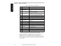
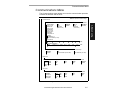
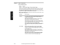
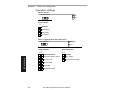
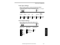
Operations Menu
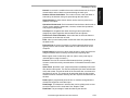
Operations Menu
The Operations menu allows you to set the operations parameters for the
decoder.
To help visualize the menu’s organization and to locate the page number
where each topic is described, see figure 2-3.
–
Operations
–
–
–
–
–
–
Continuous Read
Continuous Read 1
Output
External Level
External Edge
Serial Data
Serial Data & Edge
–
Positive
Negative
When to
Output
–
–
As Soon As
Possible
End of Read
Cycle
–
–
–
Timeout in
10 ms incs *
Timeout
New Trigger
Timeout &
New Trigger
Noread Message
(7 digits)
External Trigger
Polarity
–
End of
Read Cycle
–
–
Number of
Reads
–
–
1
User
Definable
(1 to 31)
NOREAD
User Definable
(ASCII char.)
Match Code
–
–
Disabled
Enabled
–
–
100
User Definable
(ASCII char.)
Noread
Message
–
–
Enabled
Disabled
Number of
Labels
–
–
1
User
Definable
(1 to 6)
Serial Trigger
Character
–
–
^]
User
Definable
(ASCII char.)
Bar Code
Output
–
–
Enabled
Disabled
Field
Separator
–
–
, (comma)
User
Definable
(ASCII char.)
* Divide the number entered on the command line by 100 for time in seconds.
Figure 2-3 Operations Menu Structure
MS-3000 Single Head Decoder User’s Manual
2-13
2–Menu Config.
Triggering Mode
Bold text represents default settings.
Chapter 2
Menu Configuration
Triggering Mode
Default: Continuous Read
Options: Continuous Read, Continuous Read 1 Output, External Level,
External Edge, Serial Data, Serial Data & External Edge
Allows you to establish the type of trigger event that will initiate or end the
read cycle. (See “End of Read Cycle” on page 2-16.)
2–Menu Config.
Selecting:
Continuous Read
NOTE: If Continuous Read is enabled
with Match Code, the
decoder defaults to
Continuous Read 1
Output mode.
Continuous Read 1
Outputa
NOTE: Enabling
Continuous Read 1
Output when Number of Labels (page
2-21) is set to any
number greater than
one will cause Number of Labels to default back to one.
External Level
2-14
Has this effect:
Trigger input options are disabled and the decoder is
always in the read cycle. Bar code data is decoded,
and label information is transmitted repeatedly, as
long as the label is in the range of the scan head.
When To Output options have no affect on
Continuous Read. Continuous Read is useful in
testing label or scan head functions.
Label data is immediately transmitted with Timeout
enabled for End Of Read Cycle. If the label doesn't
change, the decoder will repeat the output at the end
of each subsequent timeout period. For example, if
Timeout were set to one second, the decoder would
output the label data immediately, and then repeat
the output at intervals of one second, for as long as
the label continued to be scanned.
With Timeout disabled (that is, End Of Read Cycle
set to New Trigger), the decoder will output the
current label data immediately, but output it only
once. A new label appearing at any time in the scan
range will produce a new read output as long as the
new label is not identical to the previous label.
Allows a read cycle to be initiated by a trigger signal
from an object detector when an object appears
within the detector’s range. The read cycle endures
until the object moves out of the detector’s range
(figure -1 on page -15), unless a timeout occurs
and Timeout is enabled for End of Read Cycle (page
2-16).b
MS-3000 Single Head Decoder User’s Manual
Operations Menu
Selecting:
Has this effect:
As with Level, Edge allows a read cycle to be
initiated by a trigger signal from an object detector
when it detects the appearance of an object (rising
edge). But unlike Level mode, the removal of an
object (falling edge) does not end the read cycle.
With Edge enabled, the read cycle ends with a good
read, a timeout, or a new trigger (figure -1).
Serial Data
The decoder accepts an ASCII character from the
host or controlling device as a trigger to start a read
cycle.
Serial Data &
External Edge
The decoder accepts either an external trigger or a
serial ASCII command to start a read cycle.
a. Continuous Read 1 Output will allow an output regardless of how Good Decode Read is set.
b. Level and Edge apply to the active logic state (positive or negative) that exists while the object is
in a read cycle, between the rising edge and falling edge. For the purpose of this discussion, rising edge is the trigger signal associated with the appearance of an object and falling edge is the
trigger signal associated with the subsequent disappearance of the object.
First rising edge trigger
First trigger
An object, m ov ing in
1
1
front of the detector
beam , causes th e
first trigger (rising
O bject
detector
edge trigger) signal
O bject
detector
O bj ec t #1 , m o v i ng in
f r o n t o f t h e d et e c t o r
be a m , c a u se s th e f irst
trig g er (ris i ng ed ge
tri gg e r) sig na l t o b e se n t
to t h e d ec od e r, in it i at i n g
th e re ad cy c le .
to be sent to th e
dec od e r, initiatin g
the read cy cle.
Subsequent rising edge trigger
1
2
Sec ond trigger
O bject
detector
T he sam e o bjec t,
m ov ing out of the
detector's be am ,
c au ses a se co nd
trigger (f alling edge
trigger) signal to be
sent to th e decoder,
ending the read cy cle.
Figure 2-1 External Level Trigger Signals
O bject
detector
O bject #2, m ov ing in front of
the detec tor's bea m , caus es
a second trigger (rising edge
trigger) signal to be sent to
the dec oder.
This signal initiates a new
read cy cle a n d ends the
prev ious read cy cle p ro vid e d
that N ew T rigger or T im eout
and N ew T rigger is en abled
and a good read or tim eo ut
has not already o c curred.
Figure 2-1 External Edge Trigger Signals
MS-3000 Single Head Decoder User’s Manual
2-15
2–Menu Config.
External Edge
Chapter 2
Menu Configuration
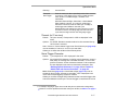
End of Read Cycle
2–Menu Config.
Default: Timeout
Options: Timeout, New Trigger, Timeout & New Trigger
Allows you to choose the conditions that will end the read cycle. The read
cycle is the time during which the decoder will receive and process label
data. When the Triggering Mode option is set in an External or Serial mode
of operation, the trigger event initiates the read cycle.
Note: The Aux Port baud rate should never exceed Host Port baud rate or auxiliary port data could be lost.
2-16
Selecting:
Has this effect:
Timeout
Can end the read cycle after a specified period of time, and
if no label has been read, causes a noread message, if
enabled, to be transmitted.
With either External Edge, Serial Data, or Serial Data &
Edge enabled, a timeout ends the read cycle.
With External Level enabled, the read cycle does not end
until the falling edge trigger occurs, and the next read cycle
does not begin until the next rising edge trigger.
With Continuous Read 1 Output enabled, a timeout initiates
a new read cycle and allows the same label to be read
again.
New Trigger
Ends the read cycle at the occurrence of a new trigger
event, and if no label has been read, causes a noread
message, if enabled, to be transmitted at the occurrence of
the new trigger event.
With either External Edge, Serial Data, or Serial Data &
Edge enabled, an edge or serial trigger ends a read cycle
and initiates the next read cycle.
With External Level enabled, a falling edge trigger ends a
read cycle. However, the next read cycle does not begin
until the occurrence of the next rising edge trigger.
MS-3000 Single Head Decoder User’s Manual
Operations Menu
Has this effect:
Timeout &
New Trigger
Ends the read cycle after a specified period of time or at the
occurrence of new trigger event, and if no label has been
read, causes a noread message, if enabled, to be
transmitted.
With either External Edge, Serial Data, or Serial Data &
Edge enabled, a timeout, or an edge or serial trigger,
whichever comes first, ends the read cycle. An edge or
serial trigger also initiates a new read cycle.
With External Level enabled, the read cycle does not end
until the occurrence of a falling edge, and the next read
cycle does not begin until the next rising edge trigger.
Timeout (in 10 ms incs)
Default:
100 (one second). Corresponds to 1000 ms displayed in the
menu.
Options: 0 to 65535. Divide the number entered on the command line by
100 for time in seconds.
Note: Timeout or Timeout & New Trigger under End of Read Cycle (page 2-16)
must be enabled for Timeout (in 10 ms incs) to take effect.
Allows you to define the duration of the timeout period.
Serial Trigger Character
Default: ^]. Corresponds to <GS> displayed in the menu.
Options: Any single ASCII character, including control characters, except a
NUL (00H), an existing host command character,1 or an on-line
protocol character. Control characters entered on the command
line are displayed in the menu as mnemonic characters. See
“Defining Special Characters” on page 2-4 and Table A-2,
“ASCII Table with Control Characters,” on page A-3.
Note: Serial Data (page 2-15) or Serial Data & Edge (page 2-15) must be
enabled for Serial Trigger Character to take effect. “N/A” is displayed in the
menu when all other triggering modes are enabled.
Allows you to define a single ASCII character as the host serial trigger character that initiates the read cycle. The serial trigger is considered an on-line
1. For example, assigning an upper case D would nullify the <D> (Enter Menu Configuration)
command. For a list of operational commands used by the decoder, see table A-1 on page 52.
MS-3000 Single Head Decoder User’s Manual
2-17
2–Menu Config.
Selecting:
Chapter 2
Menu Configuration
host command and requires the same command format as all host commands (that is, to be entered within the < > brackets).
External Trigger Polarity
2–Menu Config.
Default: Positive
Options: Positive, Negative
Note: External Level (page 2-14), External Edge (page 2-15), or Serial Data
& Edge (page 2-15) must be enabled for External Trigger Polarity to take
effect. “N/A” is displayed in the menu when all other triggering modes are
enabled.
Allows you to determine whether a positive or negative transition will initiate the read cycle.
Note: If using the Microscan object detector (P/N 99-440001-03), use positive
trigger polarity.
Noread Message
Default: NOREAD
Options: Up to seven ASCII characters (except a NUL).
Allows you to define any combination of ASCII characters (except a NUL)
up to seven characters as the noread message.
The noread message, if enabled and if no bar code label has been decoded,
will be transmitted to the host at a timeout or the end of a read cycle.
Noread Message (enable/disable)
Default: Enabled
Options: Enabled, Disabled
Note: If Noread Output is enabled, the noread message will only output if Bar
Code Output is also enabled.
Allows you to enable or disable the noread message.
Bar Code Output
Default: Enabled
Options: Enabled, Disabled
Allows you to choose whether or not to send label data (or noreads) to the
host. When disabled, a label is decoded and the read cycle transpires as
usual, but neither label data nor the noread message is transmitted to the
host. All decoder counters are updated, and the number of good reads or
noreads can be obtained via operational commands.
2-18
MS-3000 Single Head Decoder User’s Manual
Operations Menu
When to Output
Default: As Soon As Possible
Options: As Soon As Possible, End of Read Cycle
Allows you to choose when bar code data is sent to the host.
Selecting:
Has this effect:
Causes bar code data (good reads) to be
transmitted immediately upon a good decode.
End of Read Cycle
Causes bar code data output to be delayed until
the end of the read cycle.
Number of Reads Before a Good Decode
Default: 1
Options: 1 to 31
Allows you to select the number of good reads (from 1 to 31) required per
label before a good decode output.
Note: Be sure to set the value within the determined scan rate for the scanning setup so that the decoder is capable of scanning a label the required
number of times.
Match Code
Default: Disabled
Options: Disabled, Enabled
Note: A triggered mode (page 2-14 to page 2-15) must be enabled for Match
Code to take effect.
Note: If Match Code is enabled with Continuous Read, the decoder defaults
to Continuous Read 1 Output mode, and the label data must change before
the decoder will output data again, unless a timeout, if enabled, occurs.
Note: Enabling Match Code when Number of Labels is set to any number
greater than one will cause Number of Labels to default back to one.
Allows you to enter a master label into the decoder’s memory to be compared with subsequently scanned labels.
MS-3000 Single Head Decoder User’s Manual
2-19
2–Menu Config.
As Soon As Possible
Chapter 2
Menu Configuration
2–Menu Config.
With Match Code enabled, a master label can be entered in three ways:
1. With New Master Pin enabled (see page 2-31), toggling pin 25 to
ground (pin 7) enables the next good read to be the master label.
2. Sending serial command <G> enables the next good read to be the
master label.
3. Sending serial command <)XXXX)> downloads data as master
label. (Master label data is entered in place of the Xs.)
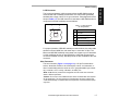
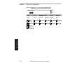
Figure 2-4 shows the sequence of operation (and reference) for setting
up and entering master labels.
* See the option/outputs available in the relay
driver you have selected.
Enable Match Code:
1. by menu selection,
2. by operational command
<E>, or
3. by serial configuration
command <Kn1>.
Enable New Master Pin:
1. by menu selection, or
2. by serial configuration
command <Kz1>.
Enter the next label scanned
as the master label:
Toggle internal pin 25
to GND (pin 7) to
enter next label
scanned as the
Read in the
master label.
1. by operational command <G>.
Download a new master
label directly into memory:
1. by operational command
<)XXXX)>.
Figure 2-4 Match Code Logic Diagram
2-20
MS-3000 Single Head Decoder User’s Manual
Compare the
master label with
subsequent labels*
Operations Menu
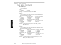
Number of Labels
Field Separator
Default: , (comma)
Options: Any available ASCII character, except NUL.
Allows you to choose the separator character to be inserted between
labels.
MS-3000 Single Head Decoder User’s Manual
2-21
2–Menu Config.
Default: 1
Options: 1 to 6
Note: If Number of Labels is set to any number greater than one while Match
Code or Continuous Read 1 Output is enabled, Number of Labels will default
back to one.
Allows you to choose the number of different labels that will be read in a
single trigger event. The labels can be a mix of any of the enabled bar
code symbologies and more than one label can be decoded per scan line.
The following conditions apply:
1. Each label must be different to be read.
2. The maximum number of characters in any one label is 31.
3. The maximum number of characters in a single scan line is 62.
4. The maximum number of characters for all labels is 128, including
preamble and postamble and all spaces and commas.
5. All noread messages are posted at the end of the data string.
6. If more than one label is within the scan beam at the same time,
label data may not be displayed in the order of appearance.
Chapter 2
Menu Configuration
Code Types Menu
The Code Types menu allows you to choose among five bar code types
and define their parameters.
Code Types
–
Bold text represents default settings.
Narrow Margins
Status
–
2–Menu Config.
–
Disabled
Enabled
Code 39
Status
Check Digit
Enabled
Disabled
–
–
–
–
Check Digit
Output
Disabled
Enabled
–
–
Large Interchar Fixed Code
Length
Gap
Disabled
Enabled
–
–
Disabled
Enabled
–
–
Code Length
–
–
Disabled
Enabled
10
User Definable
(1 to 31)
Codabar
Status
Disabled
Enabled
–
–
Start & Stop
Output
Start &
Stop Match
–
–
Enabled
Disabled
–
–
Large
Interchar Gap
Enabled
Disabled
–
–
Disabled
Enabled
Fixed Code
Length
–
–
Disabled
Enabled
Code Length
–
–
10
User
Definable
(1 to 31)
I 2 of 5
Status
–
–
Disabled
Enabled
Check Digit
–
–
Disabled
Enabled
Check Digit
Output
–
–
Disabled
Enabled
Code Length #1
–
–
10
User Definable
(even, 0 to 30)
Code Length #2
–
–
6
User Definable
(even, 0 to 30)
UPC
Status
–
–
Disabled
Enabled
EAN
–
–
Supplementals
Disabled
Enabled
–
–
–
Disabled
Enabled
Required
Separator
–
–
Enabled
Disabled
Code 128
Status
–
–
Disabled
Enabled
Fixed Code
Length
–
–
Disabled
Enabled
Code Length
–
–
10
User Definable
(1 to 31)
Figure 2-5 Code Types Menu Structure
2-22
MS-3000 Single Head Decoder User’s Manual
Separator
(character)
–
–
, (comma)
User Definable
(ASCII char.)
Code Types Menu
Note: Options listed in the command line do not always appear in the same
order as those posted in the first column of the menu.
Options can be defined for any bar code type whether or not the bar code
itself is enabled at the time.
Narrow Margins
Status
Code 39
Status
Default: Enabled
Options: Enabled, Disabled
Check Digit
Default: Disabled
Options: Disabled, Enabled
Code 39 is self-checking and does not normally require a check digit. However, for additional data integrity, a Modulus 43 check digit can be added to
the bar code message. With Check Digit and an External or Serial trigger
option enabled (see “Triggering Mode” on page 2-14), an invalid check
digit calculation will cause a noread message to be transmitted at the end of
the read cycle.
Check Digit Output
Default: Disabled
Options: Disabled, Enabled
When enabled, the check digit character is sent along with the label data.
When disabled, label data is sent without the check digit.
MS-3000 Single Head Decoder User’s Manual
2-23
2–Menu Config.
Default: Disabled
Options: Disabled, Enabled
Allows the decoder to read bar codes with quiet zones less than 10 times the
narrow-bar-width. Quiet zone is a term used to describe the minimum space at
the leading and trailing ends of a label. Each quiet zone can be as small as five
times the narrow bar element when Narrow Margins is enabled.
Chapter 2
Menu Configuration
Large Intercharacter Gap
Default: Disabled
Options: Disabled, Enabled
Allows the decoder to read labels with gaps between bar code characters
exceeding three times the narrow element width.
Fixed Code Length
2–Menu Config.
Default: Disabled
Options: Disabled, Enabled
Used to increase data integrity by ensuring that only one label length will be
accepted.
Code Length
Default: 10
Options: 1 to 31
Note: Fixed Code Length (page 2-24) must be enabled for Code Length to take
effect.
Allows you to specify the exact number of characters that the decoder will
recognize (this does not include start and stop). The decoder will ignore any
code not having the specified length.
Codabar
Status
Default: Disabled
Options: Disabled, Enabled
Start & Stop Match
Default: Enabled
Options: Enabled, Disabled
Requires the Codabar start and stop characters (a, b, c, or d) to match
before a valid read can occur.
Start & Stop Output
Default: Enabled
Options: Enabled, Disabled
Allows the start and stop characters to be transmitted with bar code data.
2-24
MS-3000 Single Head Decoder User’s Manual
Code Types Menu
Large Intercharacter Gap
Default: Disabled
Options: Disabled, Enabled
Allows the decoder to read labels with gaps between bar code characters
exceeding three times the narrow element width.
Fixed Code Length
Code Length
Default: 10
Options: 1 to 31
Note: Fixed Code Length (page 2-25) must be enabled for Code Length to take
effect.
Allows you to specify the exact number of characters that the decoder will
recognize. The decoder will ignore any code not having the specified
length.
Interleaved 2 of 5
Status
Default: Disabled
Options: Disabled, Enabled
Because I 2 of 5 is a continuous code, it is prone to substitution errors.
Hence, a code length must be defined and a bar code label containing an
even number of digits must be used. It is also recommended that a Modulus
10 check digit be used to ensure the best possible data integrity.
Check Digit
Default: Disabled
Options: Disabled, Enabled
I 2 of 5 uses a Modulus 10 check digit.
MS-3000 Single Head Decoder User’s Manual
2-25
2–Menu Config.
Default: Disabled
Options: Disabled, Enabled
Used to increase data integrity by ensuring that only label length will be
accepted.
Chapter 2
Menu Configuration
Check Digit Output
Default: Disabled
Options: Disabled, Enabled
When enabled, the check digit character is sent along with the label data.
When disabled, label data is sent without the check digit.
Code Length #1
2–Menu Config.
Default: 10
Options: 0 to 30, even. If you enter an odd number the decoder will use the
next lower number.
With I 2 of 5, two code lengths can be defined. When using only one label
length in an application, we recommend setting Code Length #2 to 0 to
ensure data integrity. If a check digit is used, it must be included in the code
length count.
Code Length #2
Default: 6
Options: 0 to 30, even. If you enter an odd number the decoder will use the
next lower number.
If using a second label, you may also specify a zero or any even code
length from 2 to 30. If not using a second label, set Code Length #2 to 0 to
ensure data integrity.
UPC
Status
Default: Disabled
Options: Disabled, Enabled
When enabled, the decoder will read UPC version A and UPC version E only.
EAN
Default: Disabled
Options: Disabled, Enabled
Note: UPC must be enabled for EAN to take effect.
When EAN is enabled, the decoder will read UPC version A, UPC version
E, EAN 13, and EAN 8. It will also append a leading zero to UPC version A
label information and transmit 13 digits. If you do not want to transmit 13
digits when reading UPC version A labels, disable EAN.
2-26
MS-3000 Single Head Decoder User’s Manual
Code Types Menu
Supplementals
Separator
Default: Enabled
Options: Enabled, Disabled
Allows you to insert a character between the standard UPC or EAN code
and the supplemental code.
Separator (character)
Default: , (comma)
Options: Any ASCII character.
Allows you to change the separator character from a comma to a new
value.
MS-3000 Single Head Decoder User’s Manual
2-27
2–Menu Config.
Default: Disabled
Options: Disabled, Enabled, Required
Note: Narrow Margins must be enabled if the gap between the standard code and
the supplemental code is between 5:1 and 10:1 (in relation to narrow-bar-width).
Allows the decoder to read supplemental bar code data that has been
appended to the standard UPC or EAN codes.
When set to Required, the decoder treats the supplemental data and the
bar code label as a single label. Also, supplemental data must be found or a
noread will result.
When set to Enabled, the decoder treats the supplemental data and the bar
code label as separate labels.
Chapter 2
Menu Configuration
Code 128
Status
Default: Disabled
Options: Disabled, Enabled
Fixed Code Length
2–Menu Config.
Default: Disabled
Options: Disabled, Enabled
Allows you to increase data integrity by ensuring that only one label length
will be accepted.
Code Length
Default: 10
Options: 1 to 31
Note: Fixed Code Length must be enabled for Code Length to take effect.
Allows you to specify the exact number of characters that the decoder will
recognize. The decoder will ignore any code not having the specified
length.
2-28
MS-3000 Single Head Decoder User’s Manual
User Outputs Menu
User Outputs Menu
The User Outputs menu allows you to configure the decoder’s output.
–
User Outputs
Beeper
Status
–
–
On Good
On Noread
Disabled
–
–
–
–
–
Laser On/Off
–
–
Disabled
Enabled
Level 4
Level 5
Level 1
Level 2
Level 3
–
–
–
Enabled
Disabled
–
–
–
–
Reverse
Video
–
–
–
Fast
Slow
Good/Bad
Polarity
Disabled
Enabled
–
–
New Master
Pin
Full Screens Relay Driver
Positive
Negative
Mismatch or
Noread
Good Match
Mismatch
Noread
Good/Bad
Pulse Width*
–
–
50 ms
User Definable
(0 to 255)
–
–
Disabled
Enabled
Command
Start Character
–
–
<
User Definable
(ASCII char.)
Serial command Echo Beep on serial Command
–
–
Disabled
Enabled
–
–
Disabled
Enabled
* Divide the number entered on the command line by 100 for time in seconds.
Figure 2-6 User Outputs Menu Structure
Beeper
Default: On Good
Options: On Good, On Noread, Disabled
A beep is emitted either after each good read of a bar code label, after each
noread, or not at all, according to the setting.
Note: The beep period will be short for triggered modes where a new trigger
occurs immediately or the output is delayed to the end of the read cycle on edge
and serial triggers.
Beeper Volume
Default: Level 4
Options: Level 4, Level 5, Level 1, Level 2, Level 3
MS-3000 Single Head Decoder User’s Manual
2-29
2–Menu Config.
–
Beeper
Speed
Beeper
Volume
Bold text represents default settings.
Chapter 2
Menu Configuration
Beeper Speed
Default: Fast
Options: Fast, Slow
Beeper Speed allows you to set the beeper to accommodate your application. The beeper takes approximately 80 ms to sound when Slow is
enabled. If your application speed is faster than 80 ms (approximately),
enable Fast.
2–Menu Config.
Full Screens
Default: Enabled
Options: Enabled, Disabled
Allows you to display either the full menu screen or just the command line.
When Full Screens is disabled, only the command line will be displayed.
Relay Driver
Default: Mismatch Or Noread
Options: Mismatch Or Noread, Good Match, Mismatch, Noread
Note: All options (except Noread) require that you enable Match Code (page
2-19) and download a master label into memory.
Allows you to determine the conditions under which a Relay Driver pulse
of 5V is output. To see your options for enabling Match Code and downloading a master label into memory, see figure 2-4, “Match Code Logic
Diagram,” on page 2-20.
Selecting:
Has this effect:
Mismatch
or Noread
Sends a pulse to pin 2 of the trigger connector when
a label’s data does not match that of the master label,
or the label is not decoded before the end of the read
cycle.
Good Match
Sends a pulse to pin 2 of the trigger connector when
a label’s data matches that of the master label.
Mismatch
Sends a pulse to pin 2 of the trigger connector
when a label’s data does not match that of the
master label.
Noread
2-30
Sends a pulse to pin 2 of the trigger connector
when no data is decoded before the end of the
read cycle.
MS-3000 Single Head Decoder User’s Manual
User Outputs Menu
New Master Pin
Laser On/Off
Default: Disabled
Options: Disabled, Enabled
Note: A serial or external trigger (see “Triggering Mode” on page 2-14) must be
enabled for Laser On/Off to take effect.
When enabled, the laser is ON only during the read cycle. When disabled,
the laser operates continuously.
Note: Laser On/Off does not relate to the <H> (Enable Laser Scanning) or <I>
(Disable Laser Scanning) operational commands on page 5-3.
Reverse Video
Default: Disabled
Options: Disabled, Enabled
When enabled, the decoder will read bar code labels with bars that are
lighter in color than their corresponding backgrounds.
Good/Bad Polarity
Default: Positive
Options: Positive, Negative
Allows you to choose between positive and negative output signals for pins
6 (good read) and 8 (noread) on the host connector and pin 2 on the trigger
connector.
MS-3000 Single Head Decoder User’s Manual
2-31
2–Menu Config.
Default: Disabled
Options: Disabled, Enabled
Note: Match Code (page 2-19) and a triggered mode (page 2-14) must be
enabled for New Master Pin to take effect.
Allows you to externally toggle pin 25 to momentarily bring it to ground (pin
7). This clears any existing master label information from memory and
records the next good read as the new master label information.
Chapter 2
Menu Configuration
Good/Bad Pulse Width
2–Menu Config.
Default: 5 (.05 seconds). Corresponds to 50 ms displayed in the menu.
Options: 0 to 255 (0 to 2.55 seconds). Divide the number entered on the
command line by 100 for time in seconds.
Allows you to set the duration of the good read/no read output signals at
host connector pins 6 and 8 by entering any number from 0 to 255.
Caution: Too long of a pulse width can cause missed labels, especially if Good/
Bad Pulse Width exceeds End of Read Cycle Timeout (see page 2-16,).
Command Start Character
Default: <
Options: Any ASCII character.
Allows you to define a new ASCII start character in a serial command.
Serial Command Echo
Default: Disabled
Options: Disabled, Enabled
When enabled, serial configuration commands (“K” commands) will be processed
and the new string for that command will be echoed back to the host. If an invalid
command is sent to the host, the decoder will echo back the current setting of that
command. For example, if the current Noread Message is “NOREAD” and
<Kk1,NONSENSE> is entered, the decoder will echo back: <Kk1,NOREAD>. In
this example the attempted entry “NONSENSE” exceeds the maximum allowable
seven characters. Therefore it is rejected and the current NOREAD message is
echoed back and remains the Noread Message.
Note: It is important to note that if a command with multiple fields is processed,
some of the fields may have been processed properly following an “invalid”
command. These changes will be in the string echoed back so that the user will
know what did or did not change.
Beep on Serial Command
Default: Disabled
Options: Disabled, Enabled
When enabled, the decoder beeps once whenever a K command is entered to
indicate that the command was accepted and processed. If an invalid command is
entered, the decoder beeps 5 times to indicate an invalid entry. However, this does
not necessarily mean that all data fields have been entered incorrectly. Only one
bad field needs to be found in order to activate the 5 beep response.
2-32
MS-3000 Single Head Decoder User’s Manual
Raster Setup Menu
Raster Setup Menu
Note: Raster Setup is applicable to the MS-1280 raster scan head only.
The Raster Setup menu allows you to set top and bottom offset values as
well as the raster motor speed.
–
Raster Setup
–
–
Enabled
Disabled
Top Offset in
Degrees
–
–
0
User
Definable
(0 to 45)
Bottom Offset in
Degrees
–
–
Sweeps per
Second
45
User Definable
(0 to 45)
–
–
2–Menu Config.
Status
Bold text represents default settings.
14
User
Definable
(0 to 135)
Figure 2-7 Raster Setup Menu Structure
Table 2-1 Raster Settings
MS-1280 Raster
Scan Head
Top
Offset = 0°
Bottom
Offset = 45°
Figure 2-8 Raster Sweep Arc
Raster
Arc
Sweeps per Second
Minimum
Maximum
1°
1
5°
1
135
75
10°
1
45
15°
1
35
20°
1
29
25°
1
23
30°
1
21
35°
1
19
40°
1
17
45°
1
14
Status
Default: Enabled
Options: Enabled, Disabled
For additional information on raster setup see the MS-1280 Raster Scan
Head User’s Manual.
Top Offset in Degrees
Default: 0 (degrees)
Options: 0 to 45 (in one-degree increments)
MS-3000 Single Head Decoder User’s Manual
2-33
Chapter 2
Menu Configuration
Note: The top offset must always be less than the bottom offset or the resulting
arc will be 0 degrees.
Top Offset in Degrees, along with Bottom Offset in Degrees, allows you to
set the raster sweep arc. See figure 2-8.
Bottom Offset in Degrees
2–Menu Config.
Default: 45 (degrees)
Options: 0 to 45 (in one-degree increments)
Note: The bottom offset must always be greater than the top offset or the resulting arc will be 0 degrees.
Bottom Offset in Degrees, along with Top Offset in Degrees, allows you to
set the raster sweep arc. See figure 2-8 on page 2-33.
Sweeps per Second
Default: 14
Options: 0 to 135
Allows you to control the raster motor speed. A “sweep” is defined as a single pass, up or down, describing the raster image.
table A-1 on page 2-33 shows minimum and maximum possible sweep
speeds at selected raster arcs. The minimum possible speed at any arc is
always one sweep per second. Maximum sweep speeds are the maximums
to which the scan head defaults—even when you enter higher speeds.
To maximize the number of scans a label will receive, select as few as possible sweeps per second. However, to ensure that the minimum required
scan lines cross the bar code label, it is essential that at least two full
sweeps occur during the time it takes for the label to pass through the readable scan width area.
For example, if the label is readable in the read range for only 1/10th of a
second, then the number of sweeps per second should be at least 20. If
readable for only 1 second, then sweeps per second (SPS) should be at
least 2. To see the formula for calculating sweeps per second, see the
MS-1280 Raster Scan Head User’s Manual.
2-34
MS-3000 Single Head Decoder User’s Manual
Chapter
3
Serial
Configuration
Chapter Contents
This chapter describes how to configure the MS-3000 single decoder by
serial commands from a host.1
All of the configuration parameters that can be changed in the menus with
the exception of Full Screens, as described in Chapter 2, “Menu Configuration,” can also be changed by serial configuration commands.
All of the serial configuration parameters, with the exception of Trigger Filter
Timing Value, also appear in the menus.
In addition, most of these configuration parameters can also be changed
with a Microscan profile card (P/N 99-500011-01), obtainable from your
Microscan representative. (See Chapter 4, “Profile Card Configuration.”)
1. The decoder communicates in full duplex, terminal mode with no handshake. It also recognizes carriage
returns and line feeds. The host or ASCII terminal with must match the following default settings before
any communication can take place: 9600 Baud Rate, Seven Data Bits, Even Parity, and One Stop Bit. If
communicating from an auxiliary terminal via the auxiliary port (pins18 and 19 of the 25 pin connector),
the serial command <D> (Enter Menu Configuration Program) is the only command that the decoder will
recognize.
MS-3000 Single Head Decoder User’s Manual
3-1
3–Serial Config.
Summary of Serial Configuration Commands...................................... 3-2
Concatenating Serial Commands ........................................................ 3-4
Serial Command Status Request......................................................... 3-4
Loss of Communications...................................................................... 3-4
Trigger Filter Timing Value................................................................... 3-5
Communications Commands............................................................... 3-6
Operations Commands ...................................................................... 3-10
Code Types Commands .................................................................... 3-12
User Outputs Commands .................................................................. 3-14
Raster Setup Commands................................................................... 3-17
Chapter 3
Serial Configuration
Summary of Serial Configuration Commands
Table 3-1 Summary of Serial Configuration Commands
Function
Host Protocol
(Not in
menu)
KF
Trigger Filter Timing Value
Kf
Protocol
Preamble
Kd
Ke
Kc
KA
KB
KT
Kb
Ka
Host
Port
Ky
KU
Kg
3–Serial Config.
Kh
Operations
Intercharacter Delay
Host Protocol Status Request
RS-422
Host Port
Aux Mode
Host Port Status Request
Triggering Mode
End of Read Cycle
Kk
Kl
Bar Code Output
Kj
Format
<KF?> (returns current value in milliseconds)
<KFtime in 10 ms increments>
<Kfprotocol,data,...>
<Kdstatus,ASCII characters>
<Kestatus,ASCII characters>
<Kcstatus>
<KAnumber>
<KBnumber>
<KT?>
<Kbstatus>
<Kabaud,parity,stop bits,data bits>
<Kymode>
<KU?>
<Kgmode>
<Khmode,time>
<Kicharacter>
<Kjpolarity>
<Kkstatus,noread message>
<Klstatus,when to output>
<Kmnumber>
<Knstatus>
<KLnumber of labels,separator character>
KV
Number of Reads
Match Code
Number of Labels
Operations Status Request
Ko
Narrow Margins
Kp
Code 39
Kq
Codabar
<Kostatus>
<Kpstatus,check digit,check digit output,
large interchar. gap,fixed length,length>
<Kqstatus,S/S match,S/S output,large interchar
gap,fixed length,length>
Kr
Interleaved 2 of 5
<Krstatus,check digit,check digit output,length 1,
length 2>
Ks
UPC/EAN
<Ksstatus,EAN status,supplementals
status,separator status,separator char.>
Kt
Code 128
Code Types Status Request
<Ktstatus,fixed length,length>
<KW?>
Km
Kn
KL
Code Types
Postamble
LRC
Host Response Timeout
Serial Trigger Character
External Trigger Polarity
Noread Message
Ki
KW
3-2
Command
Parameter
<KV?>
MS-3000 Single Head Decoder User’s Manual
User Outputs
Function
Ku
Beeper
Kv
Kz
Relay Driver Usage
New Master Pin
KC
Laser On/Off
KD
KE
Reverse Video
Good/Bad Polarity
Good/Bad Pulse Width
Command Start Character
KS
Verification Serial Command
KX
User Output Status Request
Raster Setup (1280 only)
Kw
Kx
Raster
Command
Parameter
KR
Format
<Kubeeper status,beeper volume,beeper speed>
<Kvmode>
<Kzstatus>
<KCstatus>
<KDstatus>
<Kwpolarity>
<Kxnumber>
<KEASCII character>
<KSserial command echo status,serial command
beep status, control/hex output>
<KX?>
<KRstatus,top offset,bottom offset,motor speed>
The format for a serial configuration command is,
<Kparameterdata,data,...etc.><initializing command>
When using serial configuration commands, note also the following conventions:
• Parameters and data are “case sensitive.” That is, characters must be
entered as upper or lower case, as specified.
• All data fields (except the last) must be followed by a comma (without a
space).
• If there is no change in a given field, then commas can be entered alone,
or with the existing data (for example, <Ka,,,0> or <Ka4,1,0,0>).
1. Command start character by default is a left angle bracket, <. It may be redefined by menu or serial command. However, the end character, a right angle bracket, >, cannot be changed.
2. See “Initializing serial configuration commands” on page 3-4 for definitions and examples.
MS-3000 Single Head Decoder User’s Manual
3-3
3–Serial Config.
Where:
• Less than < and greater than > symbols are included as part of the commands.1
• “parameter,” as used here, are those character(s) that precede the data.
• The “initializing command” <A> or <Z> is sent after configuration is complete. <Z> resets and saves for power up. <A> initializes the change to
RAM.2 (For more information, see page 5-3.)
For example, the following command enables UPC and saves the change
for power on: <Ks1><Z>.
Chapter 3
Serial Configuration
• All fields preceding the modified field must be included. For example, in
the RS-232 port, to change Data Bits to Eight without changing any other
field, enter either: <Ka,,,1> or <Ka4,1,0,1>.
• All fields following the modified field can be left out. For example, in the
RS-232 port, to change Baud Rate to 4800, enter <Ka3>.
(See examples on following pages.)
Initializing serial configuration commands
To ensure that a serial configuration command will take effect, you need
to follow it with one of the operational commands below:
<A> To reset but not save changes for power on
<Z> To reset and save changes for power on
For example, to change Baud Rate and reset without saving changes for
power-up, enter <Ka3><A>.
To change Baud Rate and reset, saving the changes to NOVRAM, enter
<Ka3><Z>.
3–Serial Config.
Concatenating Serial Commands
Commands can also be concatenated (added together) to a maximum of 64
characters in a single string or data block. Additional data blocks of 64 or
less characters can be sent provided there is at least a 10 ms pause
between blocks.1
For example, the following command, <Kc1><KA24><Ko1><A> enables LRC,
sets the Host Protocol Response Timeout to 24 ms, enables Narrow Margins and
resets the data buffers (without saving the changes for power-on).
Serial Command Status Request
The status of serial commands can be requested by entering the command
followed by a question mark. For example, enter <Ke?> to request the status
of Postamble. Commands KT?, KV?, KW?, KX?, and KU? are used to
request the status of groups of serial commands (see table 3-1 on page 32).
Loss of Communications
Assigning a multidrop address to a decoder or making changes to communications parameters such as Baud Rate, Parity, Stop Bits, LRC, etc. without
corresponding changes in linked device(s) can result in the loss of menu
1. Data in excess of 64 characters will reset the buffer, causing the first 64 characters of the string to be lost and indicator #1 to illuminate red 2 seconds after the end of each read cycle, until the decoder’s memory is reset.
3-4
MS-3000 Single Head Decoder User’s Manual
access. If this should occur, try gaining access to the decoder by use of a profile card1 or by entering a <D> command from an auxiliary terminal via the
auxiliary RS-232 port. If neither of these methods is available, try defaulting
the decoder. See Appendix C, “Defaulting the Decoder,” on page A-4.
Trigger Filter Timing Value
Format: <KF?>
Returns the current trigger filter timing value in milliseconds.
Format: <KFone tenth trigger filter timing value>
Allows you to set trigger filter timing. Divide the desired number of milliseconds by 10 and enter the quotient.
3–Serial Config.
1. See mode 0 in Chapter 4, “Profile Card Configuration.”
MS-3000 Single Head Decoder User’s Manual
3-5
Chapter 3
Serial Configuration
Communications Commands
Note: Changes in Communications parameters or assigning an address to the
decoder can cause loss of communications with the configuration terminal when
you exit the menu program (whether or not changes are saved for power-on).
Protocol
If selecting one of the options from 0 to 4 (Point-to-Point, Point-to-Point with
RTS/CTS, Point-to-Point with XON/XOFF, Point-to-Point with RTS/CTS and
XON/XOFF, or Polling Mode D), use this format:
Format: <Kfprotocol>
protocol:
0 = Point-to-Point
1 = Point-to-Point with RTS/CTS
2 = Point-to-Point with XON/XOFF
3 = Point-to-Point with RTS/CTS & XON/XOFF
4 = Polling Mode D
5 = Multidrop (requires
address)
6 = User Defined
7 = User Defined Multidrop
3–Serial Config.
Example: To change the Protocol to Polling Mode D, enter <Kf4>.
If selecting Multidrop (5), you must define an address and add it to the format (data B).
Format: <Kfprotocol,address>
protocol:
5 = Multidrop (requires address)
address:
Any number from 1 to 50.
Example: To change the Protocol to Multidrop with an address of 33, enter
<Kf5,33>.
If selecting User Defined (6) or User Defined Multidrop (7), you must complete the format by either choosing new parameters or concatenating
unchanged data fields (separate by commas).
Tip: For User Defined, you first select Point-to-Point <Kf0> and then User
Defined <Kf6...>. For user Defined Multidrop, you first select Multidrop <Kf5>,
then User Defined Multidrop <Kf7...>.
Format: <Kfprotocol,RES,address,
REQ,EOT,STX,ETX,ACK,NAK>
Protocol:
6 = User Defined
7 = User Defined Multidrop
Example: To select an unpolled ACK/NAK User Defined protocol with LRC
disabled, enter <Kf0><Kf6,,,,,,,^F,^U><Kc0>.1 ACK and NAK will
be displayed in the menu.2
3-6
MS-3000 Single Head Decoder User’s Manual
Communications Commands
Note: Address can be assigned any ASCII character except a null. Control characters are used to define RES through NAK (except Address). Table 3-2 lists the
control characters used for these data fields. (Refer to Table A-2, “ASCII Table
with Control Characters,” on page A-3 for more information.)
Table 3-2 Protocol Commands
Protocol Command
Control Characters
(Mnemonic displayed on (Entered in menu or serial
Microscan menu)
command)
RES
^D
Effect of Command
Reset
REQ
^E
Request
EOT
^D
Reset
STX
^B
Start of Text
ETX
^C
End of Text
ACK
^F
Acknowledge
NAK
^U
Negative Acknowledge
Format: <Kdstatus,preamble character(s)>
status:
preamble character(s):
0 = Disabled
Enter one or two preamble characters
from table A-2 on page A-3, except a
1 = Enabled
null (00H). Default is ^M.
Example: To enable Preamble with just one character, an FF (form feed),
enter <Kd1,^L>.
Postamble
Format: <Kestatus,postamble>
status:
postamble character(s):
0 = Disabled
Enter one or two postamble characters
from table A-2 on page A-3, except a
1 = Enabled
null (00H). Default characters are ^M^J.
Example: To enable Postamble with an FF (form feed) and a CR (carriage
return), enter <Ke1,^L^M>.
1. <Kf0> nulls the address and <Kc0> disables LRC.
2. A control character, although conventionally represented here and in the ASCII table on page A-3 as two
characters (^F or ^U, etc.), is actually a single ASCII character that is entered on the keyboard by holding
down the control key while pressing the desired letter.
MS-3000 Single Head Decoder User’s Manual
3-7
3–Serial Config.
Preamble
Chapter 3
Serial Configuration
LRC
Format: <Kcstatus>
status:
0 = Disabled
1 = Enabled
Example: To enable LRC, enter <Kc1>.
Host Response Timeout
Format: <KAtimeout setting>
timeout setting:
Any number from 0 to 65,000 (a zero creates an indefinite wait).
Default is 12 (ms).
Example: To change Response Timeout to 30 ms, enter <KA30>.
Intercharacter Delay
3–Serial Config.
Format: <KBtime interval>
time interval (in milliseconds between characters):
Any number from 0 to 255. Default is 0.
Example: To change Intercharacter Delay to 30 ms, enter <KB30>.
Host Port
Note: Changes made in the decoder’s communications parameters such as
baud rate, parity, stop bits, LRC, etc., must be matched in the other device(s) or
communications will be lost. If this occurs, default the decoder as described in
Appendix C — “Defaulting the Decoder.”
Format: <Kabaud rate,parity,stop bits,data bits>
baud rate:
parity:
0 = 600
3 = 4800
0 = None
1 = Even
1 = 1200
4 = 9600
2 = Odd
2 = 2400
5 = 19.2K 6 = 38.4K
stop bits:
data bits:
0 = One
1 = Two
0 = Seven
1 = Eight
Example: To change the baud rate to 2400, enter <Ka2>.
To change Data Bits to Eight without changing any other fields, enter either:
<Ka,,,1> or <Ka4,1,0,1>.
3-8
MS-3000 Single Head Decoder User’s Manual
Communications Commands
RS-422
Format: <KbRS-422 status>
RS-422 status:
0 = Disabled
1 = Enabled
Example: To enable RS-422, enter <Kb1>.
This command assumes the decoder is in RS-232 before RS-422 is
enabled. If a multidrop address has been already assigned, the decoder will
be in RS-485 communications, regardless of RS-422 status.
Host Port Status Request
Format: <KU?>
Returns status of Host Port <Ka> and RS-422 <Kb>.
Auxiliary Port
3–Serial Config.
Format: <Kystatus,baud rate,parity,stop bits,data bits>
baud rate:
status:
0 = Disabled
0 = 600
3 = 4800
1 = Transparent
1 = 1200
4 = 9600
2 = Half Duplex
2 = 2400
5 = 19.2K
6 = 38.4K
3 = Full Duplex
parity:
stop bits:
data bits:
0 = One
0 = Seven
0 = None
1 = Even
2 = Odd
1 = Two
1 = Eight
Example: To enable Half Duplex and to change the baud rate to 2400, enter
<Ky2,2>.
Communications Status Request
Format: <KT?>
Returns status of each command in the group.
MS-3000 Single Head Decoder User’s Manual
3-9
Chapter 3
Serial Configuration
Operations Commands
Triggering Mode
Format: <Kgmode>
0 = Continuous Read
1 = Continuous Read 1 Output
2 = External Level
3 = External Edge
4 = Serial Data
5 = External and Serial
Example: To select External Edge, send: <Kg3>.
End of Read Cycle
Format: <Khend of read cycle,timeout>
end of read cycle:
timeout (in 10 millisecond increments):
0= Timeout
Any number between 0 to 65,535.
Default is 100 (one seconds).
1= New Trigger
2= External and Serial
3–Serial Config.
Example: To select Timeout and change the timeout value to 6 seconds,
enter <Kh0,600>.
1
Serial Trigger Character
Format: <Kitrigger character>
trigger character:
Enter any available ASCII character (see table A-1 on page A-3).
Default is ^].
Example: To define the Serial Trigger Character as a lowercase c, enter
<Kic>.
External Trigger Polarity
Format: <Kjpolarity>
polarity:
0 = Negative
1 = Positive
Example: To change External Trigger Polarity to Negative, enter <Kj0>.
1. Avoid selecting a serial trigger character that is also an operational command. For example, an uppercase C cannot be used as a serial trigger character because it is the operational command for Enter
Read Rate Test. However, a lowercase c could be used without interfering with the read rate test.
3-10
MS-3000 Single Head Decoder User’s Manual
Operations Commands
Noread Message
Format: <Kkstatus,noread message>
status:
noread message:
0 = Disabled
Any ASCII string up to 7 digits.
Default is NOREAD
1 = Enabled
Example: To enable Noread Message and change noread message to
“Fail,” send: <Kk1,Fail>.
Bar Code Output
Format: <Klstatus,when to output>
when to output:
status:
0 = As Soon As Possible
0 = Disabled
1 = Enabled
1 = End of Read Cycle
Example: To set Bar Code Output to End of Read Cycle, enter <Kl1,1>.
Number of Reads Before a Good Decode
3–Serial Config.
Format: <Kmnumber of reads>
number of reads:
Any number from 1 to 31.
Example: To change Number of Reads to 3, enter <Km3>.
Match Code
Format: <Knstatus>
status:
0 = Disabled
1 = Enabled
Example: To enable Match Code, enter <Kb1>.
Number of Labels
Format: <KLnumber of labels, field separator>
number of labels:
field separator:
0 = One label
3 = Four labels Any ASCII character except NUL.
Default is a comma (,).
1 = Two labels
4 = Five labels
2 = Three labels 5 = Six labels
Example: To set Number of Labels to four with a dash (–) for a Field Separator, enter <KL3,–>.
Operations Status Request
Format: <KV?> Returns status of each command in the group.
MS-3000 Single Head Decoder User’s Manual
3-11
Chapter 3
Serial Configuration
Code Types Commands
Narrow Margins
Format: <Kostatus>
status:
0 = Disabled
1 = Enabled
Example: To enable Narrow Margins, enter <Ko1>.
Code 39
Format: <Kpstatus,check digit status,check digit output,large interchar.
gap,fixed code length,code length>
status:
check digit status:
check digit output status:
0 = Disabled
0 = Disabled
0 = Disabled
1 = Enabled
1 = Enabled
1 = Enabled
3–Serial Config.
large interchar.
gap status:
0 = Disabled
1 = Enabled
fixed code length status: code length:
0 = Disabled
Any number from 1 to 31.
Default is 10.
1 = Enabled
Example: To set Fixed Code Length to 30, enter <Kp,,,,1,30> or
<Kp1,0,0,0,1,30>.
Codabar
Format: <Kqstatus,start & stop match,start & stop output,large interchar.
gap,fixed code length,code length>
status:
start & stop match status: start & stop output status:
0 = Disabled
0 = Disabled
0 = Disabled
1 = Enabled
1 = Enabled
1 = Enabled
large interchar. gap
status:
0 = Disabled
1 = Enabled
fixed code length status: code length:
0 = Disabled
Any number from 1 to 31.
Default is 10.
1 = Enabled
Example: To enable Codabar and set Fixed Code Length to 9, enter
<Kq1,,,,1,9> or <Kq1,1,1,0,1,9>.
3-12
MS-3000 Single Head Decoder User’s Manual
Code Types Commands
I 2 of 5
Format: <Krstatus,check digit status,check digit output status,code length
#1,code length #2>
status:
check digit status:
check digit output status:
0 = Disabled
0 = Disabled
0 = Disabled
1 = Enabled
1 = Enabled
1 = Enabled
code length #1:
code length #2:
Zero or any even number
Zero or any even number from 2 to 30. Default
from 2 to 30. Default is 10. is 6
Example: To enable I 2 of 5 and to set Fixed Code Length #1 to 8 and Fixed
Code Length #2 to 4, enter <Kr1,,,8,4> or <Kr1,0,0,8,4>.
UPC/EAN
separator status:
0 = Disabled
1 = Enabled
separator character:
Any ASCII character (except NUL). Default is a
comma (,).
Example: To enable UPC and EAN, change supplementals to required, and
change separator character to a dash (–), enter <Ks1,1,2,1,–> or
<Ks1,1,2,,–>.
Code 128
Format: <Ktstatus,fixed code length status,code length>
status:
fixed code length status: code length:
0 = Disabled
0 = Disabled
Any number from 1
to 31.Default is 10.
1 = Enabled
1 = Enabled
Example: To enable Code 128, enable Fixed Code Length, and set Code
Length to 9, enter <Kt1,1,9>.
Code Types Status Request
Format: <KW?>
Returns status of each command in the group.
MS-3000 Single Head Decoder User’s Manual
3-13
3–Serial Config.
Format: <Ksstatus,EAN status,supplementals status,separator
status,separator character>
status:
EAN status:
supplementals status:
0 = Disabled
0 = Disabled
0 = Disabled
1 = Enabled
1 = Enabled
1 = Enabled
(UPC must also be enabled) 2 = Required
Chapter 3
Serial Configuration
User Outputs Commands
Beeper
Format: <Kubeeper status,beeper volume,beeper speed>
beeper status:
beeper volume:
beeper speed:
0 = Fast
0 = Disabled
0 = Level 1
1 = On Good
1 = Slow
1 = Level 2
2 = On Noread
2 = Level 3
3 = Level 4
4 = Level 5
Example: To enable the beeper for On Noread and set the beeper volume to
Level 5, enter <Ku2,4>.
Relay Driver
3–Serial Config.
Format: <Kvrelay driver>
relay driver:
2 = Noread
0 = Good Match
3 = Mismatch or Noread
1 = Mismatch
Example: To change Relay Driver to Noread, enter <Kv2>.
New Master Pin
Format: <Kzstatus>
status:
0 = Disabled
1 = Enabled
Example: To enable New Master Pin, enter <Kz1>.
Laser On/Off
Format: <KCstatus>
status:
0 = Disabled
1 = Enabled
Example: To enable Laser On/Off, enter <KC1>.
3-14
MS-3000 Single Head Decoder User’s Manual
User Outputs Commands
Serial Command Verification
Format: <KSserial command echo status,serial command beep
status,control/hex output>
serial command echo
status:
0 = Disabled
1 = Enabled
serial command beep
status:
0 = Disabled
1 = Enabled
control/hex output:
0 = Control
1 = Hex
Example: To enable Serial Command Echo Status and Beep Status, and Hex
output, enter <KS1,1,1>
Serial Command Echo Status
When enabled, serial configuration commands (“K” commands) will be processed
and the new string for that command will be echoed back to the host. (See “Serial
Command Echo,” on page 2-32 for more details.)
Control/hex Output
Determines the echoed display of a serial status request when ASCII characters
with control characters are entered in a serial configuration command. When set to
Control, the echoed output includes a control character as shown in the “Ctrl” column of Table A-2, “ASCII Table with Control Characters,” on page A-3.
When set to Hex, the output is the actual character entered, for example the preamble command <Ke,,CR> echoes back as >Ke,, because in Hex mode the carriage return key acts on the command. In Control mode <Ke,,^M> is returned.
User Output Status Request
Format: <KX?>
Returns status of each command in the User Output group.
Reverse Video
Format: <KDstatus>
status:
0 = Disabled
1 = Enabled
Example: To enable Reverse Video, enter <KD1>.
MS-3000 Single Head Decoder User’s Manual
3-15
3–Serial Config.
Beep on Serial Command
When enabled, the decoder beeps once whenever a K command is entered to
indicate that the command was accepted and processed. If an invalid command is
entered, the decoder beeps 5 times to indicate an invalid entry. However, this does
not necessarily mean that all data fields have been entered incorrectly. Only one
bad field needs to be found in order to activate the 5 beep response.
Chapter 3
Serial Configuration
Good/Bad Polarity
Format: <Kwpolarity>
polarity:
0 = Negative
1 = Positive
Pin 6 and 8 on host connector, and pin 2 on trigger connector.
Example: To change Good/Bad Polarity to Negative, enter <Kw0>.
Good/Bad Pulse Width
Format: <Kxrelay pulse>
duration of relay pulse:
Any number from 0 to 255.
Default is 5 (50 ms).
Pin 6 and 8 on host connector, and pin 2 on trigger connector.
Example: To set Good/Bad Pulse Width to 600 ms, enter <Kx60>.
3–Serial Config.
Command Start Character
Format: <KEcommand start character>
command start character:
Any ASCII character.
Default is <.
Example: To change Command Start Character to a colon (:), enter <KE:>.
Note: Subsequent commands must start with a colon (:). For example, enter
:D> to access the menu, or :KE<> to change back to the default character.
User Outputs Status Request
Format: <KX?>
Returns status of each command in the group.
3-16
MS-3000 Single Head Decoder User’s Manual
Raster Setup Commands
Raster Setup Commands
Format: <KRstatus,top offset,bottom offset,motor speed>
status:
top offset in degrees:
0 = Disabled
Any number from 0 to 45.
Default is 0.
1 = Enabled
bottom offset in degrees:
Any number from
0 to 45. Default is 45.
motor speed (in sweeps per second):
Any number from 0 to 135. Default is 14.
Example: To set the raster arc to 35º and the raster motor speed to 10
sweeps per second, enter <KR1,5,40,10>.
3–Serial Config.
MS-3000 Single Head Decoder User’s Manual
3-17
Serial Configuration
3–Serial Config.
Chapter 3
3-18
MS-3000 Single Head Decoder User’s Manual
Chapter
4
Profile Card
Configuration
Chapter Contents
Summary of MS-3000 Modes ....................................................... 4-2
Operating Instructions................................................................... 4-3
General Settings ........................................................................... 4-4
Communications Settings ............................................................. 4-6
Operations Settings ...................................................................... 4-8
Code Types Settings .................................................................. 4-11
User Outputs Settings................................................................. 4-11
The profile card, available from Microscan as an accessory (P/N 99500011-01), is not essential to the operation of the decoder. All configuration commands performed by the profile card can also be done by menu or
serial command. However, a profile card can speed up configuration and is
particularly useful for copying configuration from one decoder to another
and for configuring devices that have been given multidrop addresses.
MS-3000 Single Head Decoder User’s Manual
4-1
4–Profile Card.
Note: Not all configuration changes that can be done by menu configuration can be done with the profile card.
Chapter 4
Profile Card Configuration
Summary of MS-3000 Modes
Table 4-1 Profile Card Mode Descriptions
Mode
0
1
2
3
4
5
6
7
4–Profile Card.
8
9
10
11
12
13
14
4-2
Parameter
Function
Write-to-Device Downloads (copies) all of the configuration parameters from the
Function profile card to the connected decoder.
Uploads configuration data from the volatile RAM of the decoder to
Read Function
the non-volatile RAM of the profile card.
Default Sets unit to the default configuration settings.
Menu Enters the menu program while decoder is in polled mode.
Combines the write function from mode 0 with the address function of
Write & Assign Address mode 2. Downloads a multidrop address as well as all of the
configuration parameters in the profile card.
Assigns user-selected multidrop address to the decoder by using
Assign Multidrop
data switches 1-6. Binary representation of the multidrop address is
Address
used (the range is 1 to 50).
Baud Rate Defines Baud Rate for the host port.
Parity Defines Parity for the host port.
Stop Bits Defines Stop Bits for the host port.
Data Bits Defines Data Bits for the host port.
Preamble Enables/disables Preamble.
Postamble Enables/disables Postamble.
Protocol Defines the communications protocol.
RS-422 Enables/disables RS-422.
Aux Port Sets Aux. Port operation mode.
Triggering Mode Defines Triggering Mode.
End of Read Cycle Defines End of Read Cycle.
Bar Code Output Enables/disables Bar Code Output.
When to Output Defines the conditions for When to Output.
External Trigger Polarity Defines External Trigger Polarity (negative/positive).
Match Code Enables/disables Match Code.
Noread Message Enables/disables Noread Message.
Sets the trigger timeout value. The range is 1-255 for corresponding
Timeout in 10 ms inc.
values of 0.1 to 25.5 seconds.
Serial Trigger Assigns the Serial Trigger Character. (See the ASCII table on page
Character A-3 for decimal values and corresponding characters.)
Number of Reads Sets the number of reads for a good decode from 1-31.
Narrow Margins Enables/disables Narrow Margins for all code types.
Code Types Enables individual bar code types or Autodiscriminate.
Beeper Volume Sets the beeper volume.
Beeper Sets the conditions when the beeper is emitted.
Relay Driver Defines the mode selection for programmable output.
Full Screens Enables/disables Full Screens.
Good/Bad Polarity Sets the Polarity of output pulses.
New Master Pin Enables/disables New Master Pin.
Laser On/Off Enables/disables Laser On/Off.
Reverse Video Enables/disables Reverse Video.
MS-3000 Single Head Decoder User’s Manual
Profile Card Configuration
Operating Instructions
The profile card obtains all operating voltages from the decoder. Turn the
decoder off before starting procedures.
1. With the decoder OFF, insert the end of the profile card which is
labeled DECODER into the port labeled HOST on decoder.
ON
Data switches are on
the left, mode
switches on the right.
Note: Be sure all of the
data switch settings are
correct for the selected
mode before pressing the
load button.
DECODER
3. Set the mode and
data switches to the
desired settings.
LOAD
PROFILE CARD
O
N
1 2 3 4 5 6 7 8
O
N
12 3 4
D AT A
TERMINAL
2. Turn decoder ON.
MO DE
Figure 4-1 Profile Card
4. Press the LOAD button.
5. A beeper will sound. This initializes the change and saves it to non-volatile RAM for access on power-up.
6. When the configuration is complete, turn power OFF to the decoder
and remove the profile card.
MS-3000 Single Head Decoder User’s Manual
4-3
4–Profile Card.
If using RS-232 (only) and communication between the host and the
decoder is desired with the profile card, connect a cable to the profile card
end labeled TERMINAL and connect it to the host.
Chapter 4
Profile Card Configuration
General Settings
Mode 0: Write, Read, Default, Menu
Mode Switches
= On
= Off
Data Switches
1 2 3 4
Write
Read
Default
Menu
4–Profile Card.
Note: Unintentional defaults may occur when using the profile card‘s write
functions (modes 0 and 1) to copy configuration changes from versions -26
and earlier to versions -27 and later (and vice versa), and when copying
from versions -27 through -31 to versions -32 and later (and vice versa)
of Microscan standard firmware.1 To solve, you can change all EPROMs
to the same firmware version, use a separate profile card for each version
group, or use a single profile card to first make all configuration copy
changes within one group (those with all earlier or all later versions) and
then, after individually changing the settings in one decoder of the second
group, copying them to the other decoders in that group.
1. The firmware number is 35-213001-XX for the MS-3000 single head decoder. The XX
is substituted here for the version number. The firmware version can be found on a
label on the EPROM, displayed in the heading of the Main menu in the Configuration
program, or on later versions, displayed by invoking the <#> serial operational command. You can also call-in the serial numbers of the decoders to Microscan to get the
firmware versions issued with those decoders.
4-4
MS-3000 Single Head Decoder User’s Manual
Profile Card Configuration
Mode 1: Write Configuration and Assign Address
Mode Switches
= On
= Off
Data Switches
Address
a
1 2 3 4 5 6
Address
Address
1 2 3 4 5 6
Address
1 2 3 4 5 6
1 2 3 4 5 6
14
27
40
2
15
28
41
3
16
29
42
4
17
30
43
5
18
31
44
6
19
32
45
7
20
33
46
8
21
34
47
9
22
35
48
10
23
36
49
11
24
37
50
12
25
38
13
26
39
4–Profile Card.
1
a. Use these switch settings for mode 2, 9, 10, and 11.
MS-3000 Single Head Decoder User’s Manual
4-5
Chapter 4
Profile Card Configuration
Communications Settings
Note: Changes in Communications parameters or assigning an address to
the decoder can cause loss of communications with the configuration terminal when you exit the menu program (whether or not changes are saved for
power-on).
Mode 2: Address
Mode Switches
= On
= Off
Address selection for mode 2 is identical to mode 1.
See mode 1 for switch settings.
Mode 3: Host Port Baud Rate, Parity, Stop Bits, Data Bits
Mode Switches
= On
= Off
Data Switches
Baud Rate
Parity
Stop Bits
Data Bits
123
6
7
45
600
None
One
Seven
1200
Even
Two
Eight
2400
Odd
4–Profile Card.
4800
9600
19200
38400
4-6
MS-3000 Single Head Decoder User’s Manual
Profile Card Configuration
Mode 4: Preamble, Postamble
Mode Switches
= On
= Off
Data Switches
Preamble
Postamble
1
2
Disabled
Disabled
Enabled
Enabled
Mode 5: Protocol, Host Port RS-422
= On
Mode Switches
= Off
Data Switches
Protocol
RS-422
123
4
Point-to-Point
Disabled
Point-to-Point with RTS/CTS
Enabled
Point-to-Point with XON/XOFF
Point-to-Point with RTS/CTS & XON/XOFF
4–Profile Card.
Polling Mode D
Multidrop
User Defined
User Defined Multidrop
MS-3000 Single Head Decoder User’s Manual
4-7
Chapter 4
Profile Card Configuration
Operations Settings
Mode 6: Aux Port
Mode Switches
= On
= Off
Data Switches
Aux port mode:
12
Disabled
Transparent
Half Duplex
Full Duplex
Mode 7: Triggering Mode, End of Read Cycle
Mode Switches
= On
4–Profile Card.
= Off
Data Switches
Triggering Mode
End of Read Cycle
123
45
Continuous Read
Timeout
Continuous Read 1 Output
New Trigger
External Level
Timeout & New Trigger
External Edge
Serial Data
Serial Data & Edge
4-8
MS-3000 Single Head Decoder User’s Manual
Profile Card Configuration
Mode 8: Bar Code Output, When to Output, External Trigger
Polarity, Match Code, Noread Message
Mode Switches
= On
= Off
Data Switches
Bar Code
Output
When to
Output
External
Trigger
Polarity
Match
Code
Noread
Message
1
2
3
4
5
Disabled
As Soon as Possible
Negative
Disabled
Disabled
Enabled
End of Read Cycle
Positive
Enabled
Enabled
Mode 9: Timeout
Mode Switches
= On
= Off
Since the number of profile card settings is limited to 255, trigger timeouts
entered from the profile card can only affect a range from 0.1 seconds to
25.5 seconds, in tenths of a second.
To set Timeout, multiply the desired number of seconds for timeout by 10
and enter the result in binary format.
MS-3000 Single Head Decoder User’s Manual
4-9
4–Profile Card.
See mode 1 for switch settings for timeout ranges from 0.1 seconds to 5
seconds. (Although not shown for mode 1, switches 7 and 8 are OFF for 1
through 50.) See “Binary Calculations” on page 4-13 for timeout
ranges from 5.1 seconds to 25.5 seconds.
Chapter 4
Profile Card Configuration
Mode 10: Serial Trigger Character
= On
Mode Switches
= Off
You can define the Serial Trigger Character with an ASCII character of your
choice, or you can use the samples provided below. To use other ASCII
characters, see the ASCII table in appendix B for characters and their corresponding decimal values. See mode 1 for values from 1 to 50, or “Binary
Calculations” on page 4-13 for decimal values from 51 to 255.
Data Switches
ASCII Decimal
Number
Sample Serial Trigger
ASCII Characters
29
^]
49
1
65
A
90
Z
12345678
Mode 11: Number of Reads Before a Good Decode
Mode Switches
= On
= Off
4–Profile Card.
The range for Number of Reads before a Good Decode is 1-31. See mode
1 for switch settings.
4-10
MS-3000 Single Head Decoder User’s Manual
Profile Card Configuration
Code Types Settings
Mode 12: Code 39, Codabar, I 2 of 5, UPC, Code 128, Narrow Margins
Enabling data switches 1 through 5 will autodiscriminate for all code types.
Mode Switches
= On
= Off
Data Switches
Code 39
Codabar
I 2 of 5
UPC
Code 128
Narrow
Margins
1
2
3
4
5
6
Disabled
Disabled
Disabled
Disabled
Disabled
Disabled
Enabled
Enabled
Enabled
Enabled
Enabled
Enabled
User Outputs Settings
Mode 13: Beeper Volume, Beeper Enable, Beeper Speed
Mode Switches
= On
= Off
Beeper Enable
Beeper Speed
123
45
6
Level 1
Disabled
Fast
Level 2
On Good Read
Slow
Level 3
On Noread
4–Profile Card.
Data Switches
Beeper Volume
Level 4
Level 5
MS-3000 Single Head Decoder User’s Manual
4-11
Chapter 4
Profile Card Configuration
Mode 14: Relay Driver, Full Screens, Good/Bad Polarity,
New Master Pin, Laser On/Off, Reverse Video
Mode Switches
= On
= Off
Data Switches
Relay
Full
Driver
Screens
Good/Bad
Polarity
New
Master Pin
Laser
On/Off
Reverse
Video
12
4
5
6
7
3
Good
Match
Disabled
Negative
Disabled
Disabled
Disabled
Mismatch
Enabled
Positive
Enabled
Enabled
Enabled
Noread
4–Profile Card.
Mismatch
or Noread
4-12
MS-3000 Single Head Decoder User’s Manual
Profile Card Configuration
Binary Calculations
Data switch settings for values 51 to 255 must be determined by the user
with binary calculation. (Specifically, the timeout values for 51 to 255 in
mode 9 and various serial trigger character selections in mode 10.)
The eight data switches on the profile card represent the eight data bits that
define any number from 0 to 255 in binary format. To convert a number to
its binary equivalent:
1. Determine which decimal equivalent (1, 2, 4, 8, 16, 32, 64, 128) is the
largest number not exceeding the number to convert.
2. Put a one (1) above that number to indicate an ON position.
For example, table 4-2 shows the calculation process for the number 250.
The first one (1) is placed in the eighth bit column over the number 128,
since that is the largest possible decimal equivalent to use.
Table 4-2 Calculating Binary Conversion
Data Switches
1
2
3
= On
4
5
6
7
8
Data Switches (bit representation)
Data Switch Settings
1
1
1
1
1
1
Binary Code
2
10 26 58 122
Remainder Numbers
250
2
4
8
16 32 64 128
<--- Number to Convert
Decimal Equivalent
3. Subtract the decimal equivalent from the original number.
4. Place the remainder above the next largest decimal equivalent that
does not exceed the remainder number.
5. Put a one (1) above that number.
6. Continue this process until the remainder equals zero (0), as follows:
250 -128=122, -64=58, -32=26, -16=10, -8=2, -2=0
OFF positions on the data switches result from:
• Decimal equivalent numbers passed over because they are greater than
the remainder (the third bit in table 4-2),
• Decimal equivalent numbers not used because the formula has terminated with a remainder of zero (0) (the first bit in table 4-2).
MS-3000 Single Head Decoder User’s Manual
4-13
4–Profile Card.
1
= Off
Profile Card Configuration
4–Profile Card.
Chapter 4
4-14
MS-3000 Single Head Decoder User’s Manual
Chapter
5
Operational
Commands
Chapter Contents
Summary of Operational Commands ........................................... 5-2
Program Management Commands............................................... 5-3
Device Control Commands........................................................... 5-3
Code Type Commands................................................................. 5-4
Counter Commands...................................................................... 5-4
Test Commands ........................................................................... 5-5
Status Commands ........................................................................ 5-5
Master Label Commands.............................................................. 5-5
This chapter describes of all serial operational commands and their functions.
See table 5-1 on page 5-2 for quick reference.
On-line serial operational commands are sent from the host to the decoder to
carry out routine operations “on the fly” as distinguished from serial configuration commands which are generally used in initial setup.1
Operational commands are preceded by a < left angle bracket symbol (unless
redefined by Command Start Character command) and followed by a > right
angle bracket symbol.2
2. Command start character by default is a left angle bracket, <. It may be redefined by menu or
serial command. However, the end character, a right angle bracket, >, cannot be changed.
MS-3000 Single Head Decoder User’s Manual
5-1
4–Operations
1. The decoder will only recognize a <D> serial command (Enter Menu Configuration Program)
from an auxiliary terminal.
Chapter 5
Operational Commands
Summary of Operational Commands
Table 5-1 Summary of Operational Commands
Command Type
Program
Management
Command
Software Reset (does not save for power-on)
<D>
Enter Configuration Mode
<Z>
<Bdata>
Device
Control
Code Types
Counters
Test
Status
4–Operations
Master Label
Result
<A>
Save Configuration for Power-on
Echo Data to Aux Monitor
<H>
Enable Laser Scanning
<I>
Disable Laser Scanning
<L>
Host Relay Driver
<P>
Autodiscriminate All Codes
<Q>
Enable Code 39 Only*
<R>
Enable Codabar Only*
<S>
Enable I 2 Of 5 Only*
<N>
Noread Counter
<O>
Noread Counter Reset
<T>
Trigger Counter
<U>
Trigger Counter Reset
<V>
Match Code (or Good Read) Counter
<W>
Match Code Counter Reset
<X>
Mismatch Counter
<Y>
Mismatch Counter Reset
<C>
Enter Read Rate Test
<m>
Enter Scan Rate Test
<J>
Exit Read Rate or Scan Rate Test
<#>
Display Software Part Number
<!>
Display Checksum of EPROM
<E>
Enable Match Code Option*
<F>
Disable Match Code Option*
<G>
<)XXXX)>
Store Next Label Scanned as Master Label
Download Master Label Information
<)>
Request Master Label Information
<))>
Delete Master Label Information
* Can also be accomplished in configuration menu and serial configuration command.
5-2
MS-3000 Single Head Decoder User’s Manual
Operational Commands
Program Management Commands
<A>
Initialize
<A> Software Reset. Initializes all serial
configuration commands in RAM and
RAM
resets all counters and operating parameROM
NOVRAM
ters. Changes for Baud Rate, Stop Bits,
Code Length, etc. do not take effect until
this command is sent.
Note: Software Reset will cause the numeric counters in use to lose their count;
record all data that you wish to save prior to sending this command.
<D> Enter Configuration Mode. Enters the menu configuration program. See
Chapter 2, “Menu Configuration.”1
Initialize
<Z>
<Z> Save Configuration for Power-on.
Saves the current configuration to nonvolaRAM
tile memory for availability on power-on.
ROM
NOVRAM
The values of numeric counters are not
saved by this command.
Note: The <Z> Save Configuration command can be executed 10,000 times. In
normal usage this will exceed the life of the decoder. If frequent changes to the
operating parameters are required, the <Z> command should be used only
when the current configuration has been changed and the changes are to be
permanent.
Device Control Commands
<Bdata> Echo Data to Aux Monitor. Echoes data from host to auxiliary monitor (see Appendix H, “Auxiliary Monitor,” on page A-13 for more detail).
<H> Enable Laser Scanning (Laser On).
<I> Disable Laser Scanning (Laser Off). This feature is useful during
extended periods of time when no bar code labels are being scanned. Disabling laser scanning will not affect any downloaded commands to the decoder.
The decoder remains active during this period.
<L> Host Relay Driver. Allows you to send a pulse (at any time regardless of
Match Code or Relay Driver status) to pin 2 of the trigger connector.
Code Type Commands
1. The <D> command is the only serial command that the MS-3000 decoder will recognize from
an auxiliary terminal.
MS-3000 Single Head Decoder User’s Manual
5-3
4–Operations
<P> Autodiscriminate All Codes. Enables the decoder to decode all available
bar code types without changing decoder configuration settings.
Chapter 5
Operational Commands
NOTE: For maximum scanning speed, enable only those bar code symbologies
used in the application.
<Q> Enable Code 39 Only. Allows only Code 39 labels to be read.
<R> Enable Codabar Only. Allows only Codabar labels to be read.
<S> Enable I 2 of 5 Only. Allows only Interleaved 2 of 5 labels to be read.
Counter Commands
4–Operations
The Xs in all counter commands denote a numeric value from 00000 to 65,535.
After reaching the maximum numeric limit of 65,535, you will receive an error
message and the counter will automatically rollover and start counting again at
00000. To obtain the cumulative total of counts after the rollover has occurred,
add 65,536 per each rollover (the decoder does not keep track of the number of
rollovers) to the current count.
Note: You will lose all counter values if power to the decoder is cycled, when
sending the <A> command, or upon entering and exiting configuration setup
menus.
Note: If you activate the counter command during a read cycle, the decoder will
not output the count until the read cycle ends.
<N> Noread Counter. The message N/XXXXX displays the total number of
noreads that have occurred since power-on or the last Noread Counter Reset
command.
<O> Noread Counter Reset. Sets Noread Counter to 00000.
<T> Trigger Counter. The message T/XXXXX displays the total number of
triggers since power-on or the last Trigger Counter Reset command.
<U> Trigger Counter Reset. Sets the trigger counter to 00000.
<V> Match Counter (or Good Read Counter). The message V/XXXXX displays the total number of good reads matching the master label since power-on
or the last Match Counter Reset command. This counter is always enabled, but
will only work as a match count when Match Code option is enabled. If the
Match Code option is not enabled, this counter adds the number of good reads,
or decodes. This count can be requested at any time.1
<W> Match Counter Reset. Sets the Match Counter to 00000.
<X> Mismatch Counter. The message X/XXXXX displays the number of
labels successfully read that do not match the master label since power-on or
the last Mismatch Counter command.
<Y> Mismatch Counter Reset. Sets the Mismatch Counter to zero.
1. Can also be used as a good read counter when Match Code is not enabled.
5-4
MS-3000 Single Head Decoder User’s Manual
Operational Commands
Test Commands
<C> Enter Read Rate Test. Instructs the
decoder to output the percentage of scans
decoded. The read rate can vary dramatiRead Rate
cally due to the angle and location of the
Percentage
label in relation to the scan beam. This test
Label
is very useful in aligning and positioning the
Data
scan head during installation.
<m> Enter Scan Rate Test. Displays the current number of scans per second
produced by the spinning mirror.
<J> Exit Read Rate or Scan Rate Test. Ends the read rate test or scan rate
test and returns to read or ready mode.
Status Commands
<#> Display Software Part Number. Displays software part number.
<!> Display Checksum of EPROM. Displays a four-digit hex number (corresponding to a given firmware version) used to verify a decoder’s EPROM.
Master Label Commands
MS-3000 Single Head Decoder User’s Manual
5-5
4–Operations
<E> Enable Match Code Option. Identical to Match Code command on page
2-19.
Instructs the decoder to compare bar code labels being scanned with a master
label that has been entered in nonvolatile or volatile RAM, and may under certain conditions send a relay driver signal to pin 2 of the trigger connector. If no
master label has been entered, every decoded label will be a “mismatch” and
will increment the mismatch counter by one.
Enable Match Code Option is intended for use when the decoder is in a triggered mode. If the Match Code option is enabled in the Continuous Read
mode, the decoder defaults to Continuous Read 1 Output mode, and the label
data must change before the decoder will output data again, unless a timeout, if
enabled, occurs.
See “Match Code” on page 2-19 and “Relay Driver” on page 2-30.
<F> Disable Match Code Option. Disables Match Code.
<G> Store Next Label Scanned as Master Label. Causes the decoder to use
the next bar code label read as the master label if Match Code option has been
enabled. All subsequently decoded labels are compared against the master
label information stored in RAM. (See “Match Code” on page 2-19.)
<)XXXX)> Download Master Label Information. Downloads master label
information from the host or a terminal. The master label information can be
Chapter 5
Operational Commands
4–Operations
downloaded at any time, and can be saved in nonvolatile memory with a <Z>
command. A stored master label will not affect standard operation unless
Match Code option is enabled.
The Xs denote alphanumeric data, from 1 to 31 characters.
<)> Request Master Label Information. Immediately sends the master label
information to the host. To prevent conflicts with outputting label data, first send
the <I> command (Disable Laser Scanning (Laser Off)).
<))> Delete Master Label Information. Deletes master label information that
has previously been loaded by either <)XXXX)> Download Master Label Information Command or <G> Store Next Label as Master Label command.
Note: If the master label information has previously been stored in nonvolatile
RAM (by a <Z> command), sending an <A> Reset or cycling the power will
restore that information.
5-6
MS-3000 Single Head Decoder User’s Manual
Contents
Appendix A — Decoder Specifications ...............................................A-2
Appendix B — ASCII Table.................................................................A-3
Appendix C — Defaulting the Decoder ................................................A-4
Appendix D — Troubleshooting ...........................................................A-6
Appendix E — Interfacing with the MS-90 Scan Head .......................A-9
Appendix F — Bar Code Symbology .................................................A-11
Appendix G — Interface Standards ...................................................A-12
Appendix H — Auxiliary Monitor ........................................................A-13
Appendix I — Multidrop Communications ...............................................A-17
Appendix J — Glossary of Terms ......................................................A-21
MS-3000 Single Head Decoder User’s Manual
A-1
Appendices
Appendices
Appendix A — Decoder Specifications
Mechanical (MS-2000)
Electrical Characteristics
Length: 5.8 in. (147.3 mm) Width: 5.8 in. (147.3 mm)
Height: 1.0 in. (25.4 mm)
Weight: 7.5 oz. (213 grams)
Power Supply Requirements:
+12 VDC regulated @ 40 mA maximum
with 20 mV p-p max. ripple
–12 VDC regulated @ 40 mA maximum
with 20 mV p-p max. ripple
+5 VDC regulated @ 300 mA maximum
with 200 mV p-p max. ripple
Fro nt
Me as u r e m e n ts in in c h es
( m il l i m et er s)
1.0 "
(25.4)
Default Communications Settings
3.8" (96.52)
4.5 " (1 14.3 0)
0.1 60" (4.0 6)
D ia. (4 places)
5.8" (147.32)
Appendices
Appendices
Baud Rate: 9600
Parity: Even
Stop Bits: One
Data Bits: Seven
Environment
5.2 " (1 32.0 8)
Operating Temperature: 32° to 113°F (0° to 45°C)
Storage Temperature: –58° to 158°F (–50° to 70°C)
Humidity: Up to 95% (non-condensing)
0.0 30" (7.6 2)
5.8 " (1 47.3 2)
Status Lights
Table A-1 Status Lights
Figure A-1 MS-2000
Mode
Continuous
Read or Continuous Read 1 Output
Mechanical (MS-3000)
Length: 6.2 in. (157.5 mm) Width: 6.6 in. (167.6 mm)
Height: 1.35 in. (34.3 mm) Weight: 16 oz. (453 grams)
Fr o nt
Measurements in inches (millimeters)
1.8 5"
Triggered Mode
(External or
Serial Trigger)
Optional foot pads
(4 places)
(46.99)
2.5 "
(63.5)
Flashes when a
good read occurs.
Illuminates at
the end of a
read cycle and
remains ON until
a new trigger
occurs.
Illuminates when a
good read occurs
and remains ON
until a new trigger
occurs.
a
6/32 threads
(4 places)
0.5 "
5.6 "
(12.7)
(142 .24)
Illuminates when a
good read occurs
and remains ON
until the scanner’s
data is sent to the
concentrator.
IND 1 LED indicates a good read. Illuminates red when a serial data overflow
occurs and green when a bar code label is decoded.
b IND 2 LED indicates a “ready” condition. Illuminates red at the end of a read
cycle, indicating that the scanner is ready to accept a new trigger.
Figure A-2 MS-3000
A-2
IND 2 (lighted)b
Faintly flashes
when a good
read occurs.
Polled Mode
(Multidrop, Polling Mode D, and User defined.
User Defined
Multidrop)
6.2 "
(157 .48)
IND 1 (lighted)a
MS-3000 Single Head Decoder User’s Manual
ASCII Table
Table A-2 ASCII Table with Control Characters
Dec
Hex
Mne
Ctrl
Dec
Hex
Ch
Dec
Hex
Ch
Dec
Hex
Ch
00
01
00
01
NUL
SOH
^@
^A
32
33
20
21
SP
!
64
65
40
41
@
A
96
97
60
61
`
a
02
03
02
03
STX
ETX
^B
^C
34
35
22
23
"
#
66
67
42
43
B
C
98
99
62
63
b
c
04
05
04
05
EOT
ENQ
^D
^E
36
37
24
25
$
%
68
69
44
45
D
E
100
101
64
65
d
e
06
07
06
07
ACK
BEL
^F
^G
38
39
26
27
&
'
70
71
46
47
F
G
102
103
66
67
f
g
08
09
08
09
BS
HT
^H
^I
40
41
28
29
(
)
72
73
48
49
H
I
104
105
68
69
h
i
10
11
0A
0B
LF
VT
^J
^K
42
43
2A
2B
*
+
74
75
4A
4B
J
K
106
107
6A
6B
j
k
12
13
0C
0D
FF
CR
^L
^M
44
45
2C
2D
,
-
76
77
4C
4D
L
M
108
109
6C
6D
l
m
14
0E
SO
^N
46
2E
.
78
4E
N
110
6E
n
15
16
0F
10
SI
DLE
^O
^P
47
48
2F
30
/
0
79
80
4F
50
O
P
111
112
6F
70
o
p
17
18
11
12
DC1
DC2
^Q
^R
49
50
31
32
1
2
81
82
51
52
Q
R
113
114
71
72
q
r
19
20
13
14
DC3
DC4
^S
^T
51
52
33
34
3
4
83
84
53
54
S
T
115
116
73
74
s
t
21
22
15
16
NAK
SYN
^U
^V
53
54
35
36
5
6
85
86
55
56
U
V
117
118
75
76
u
v
23
24
17
18
ETB
CAN
^W
^X
55
56
37
38
7
8
87
88
57
58
W
X
119
120
77
78
w
x
25
26
19
1A
EM
SUB
^Y
^Z
57
58
39
3A
9
:
89
90
59
5A
Y
Z
121
122
79
7A
y
z
27
28
1B
1C
ESC
FS
^[
^\
59
60
3B
3C
;
<
91
92
5B
5C
[
\
123
124
7B
7C
{
|
29
30
1D
1E
GS
RS
^]
^^
61
62
3D
3E
=
>
93
94
5D
5E
]
^
125
126
7D
7E
}
~
31
1F
US
^_
63
3F
?
95
5F
_
127
7F
∆
MS-3000 Single Head Decoder User’s Manual
A-3
Appendices
Appendix B — ASCII Table
Appendices
Appendices
Appendix C — Defaulting the Decoder
Defaulting the decoder resets the decoder configuration parameters to their
original default values.
Defaulting is necessary if:
• You wish to quickly restore default settings to the configuration program
after making some temporary changes.1
• Communications between the decoder and another device are interrupted
because of incompatible settings (for example, a terminal is set to communicate at 9600 baud, but the decoder is configured at 38.4K baud).
• The decoder has been assigned a polling address and you wish to access
the decoder’s menu.
Access to the configuration menus of a decoder that is in a polled mode can
be forced by use of a profile card (see mode 0 in Chapter 4, “Profile Card
Configuration”), or by sending the <D> command from an auxiliary terminal via the auxiliary RS-232 port.
Using the Profile Card
OFF
LOAD
TERMINAL
2. Connect end of the
profile card labeled
“DECODER” to the
decoder’s host connector.
ON
DECO DER
Procedure:
1. Turn power to the
decoder ON.
PROFILE CARD
O
N
1 2 3 4 5 6 7 8
O
N
1 2 3 4
DATA
MODE
Figure A-3 Profile Card Default Setting
3. Set all four “MODE”
switches to OFF and
set number 3 “DATA” switch to ON (as shown in figure A-3).
4. Press the “LOAD” button.
5. Listen for two beeps in succession (the second louder than the first). If the
beeps do not occur as described, repeat the default procedure.
1. There are no menu options or host commands for resetting the configuration program.
A-4
MS-3000 Single Head Decoder User’s Manual
Defaulting the Decoder
If a profile card is not accessible, it is necessary to default the decoder by
shorting pins 7 and 11.
Caution: Be certain that the correct pins are shorted. Shorting the wrong
pins can cause serious damage to the unit.
Procedure:
1. Turn power to the decoder ON.
2. Locate pins 7 and 11 on the host connector (figure A-4) and mark with
a pen.
(Use a small length of light wire approx. 4 inches, 18 to 26 gauge for
shorting.)
3. Momentarily short pins 11 and 7. Listen for a series of short beeps.
Within 3 seconds, short pins 11 and 7 again. A longer beep should be
heard. If not, repeat the process.
Note: Using switching
power supplies as a power
source is not recommended due to excessive
ripple characteristics.
Pin 11
Pin 7
Figure A-4 Host Connector
Default Pins
MS-3000 Single Head Decoder User’s Manual
A-5
Appendices
Shorting Pins 7 and 11
Appendices
Appendices
Appendix D — Troubleshooting
The MS-3000 decoder, when used correctly with a properly adjusted scan
head, should produce good reads (see scan head user’s manual). If not,
A-3 lists some of the more common problems associated with setting up
and using the decoder. If you are unable to locate or correct the problem,
call your Microscan representative.
Table A-3 Troubleshooting Table
Problem
Possible Cause
Power indicator does not
Power supply problem
illuminate when
decoder is ON
Menu does not
display when
configuration
command is
sent
A-6
Have technician measure AC input voltage
and power supply DC output voltages.
Replace if power supply is not supplying correct voltages.
Host cable defective or not Check cable connections and wiring
wired properly
(see “Attach Cabling,” on page 1-3).
Wrong configuration command (or lower case d)
sent
Verify that the <D> serial command (with an
upper case D) is being sent.
Decoder configuration set- Reset decoder to default and/or match host
tings do not match host's
settings with decoder's.
Host cable defective
Decoder does
not transmit or
decode labels
(decoder indicator lights on
but no data is
displayed on
screen)
Solution
Ensure the cable is correctly wired (see table
1-5 on page 1-8).
Wrong label type
(different label type being
scanned than that enabled
in firmware)
Check label configuration settings to be certain that they match the label type being
scanned. If label type is in doubt, enter <P>
(the Autodiscriminate All Codes command).
Ensure that Fixed Code Length and Checksums, if enabled, are set correctly.
Poor label quality
Scan a label that is known to be good.
Decoder not configured
properly
Reset decoder to default and/or match host
settings with decoder’s.
Excessive ambient light,
sunlight, or strobes
Shield the bar code and/or scan head to verify
that excessive light is not the problem.
Faulty scan head
Try another scan head that is known to be
good.
Faulty cable to scan head
Try another scan head cable.
MS-3000 Single Head Decoder User’s Manual
Troubleshooting
Problem
Decoder does
not transmit or
decode labels
(decoder indicator lights on
but no data is
displayed on
screen)
Possible Cause
Decoder is not triggered
when in external mode.
Ensure trigger device is operating properly.
Do Read Rate Test <C>. If it reads successfully, the problem is triggering.
Decoder is not triggered
when in serial mode.
Ensure serial trigger character is sent with start/
stop characters (a left angle bracket < (unless
redefined) and a right angle bracket >).
Power supply
problem
Have technician measure AC input voltage and
power supply DC output voltages. Replace if
power supply is not supplying correct voltages.
External electrical noise
See “Ground and Shield Considerations,” on page 1-14.
Incorrect firmware for
application
Some applications may require custom firmware. Call your Microscan representative.
Scan head is not connected properly
Ensure that the modular cable is inserted into
the modular connectors. Inspect cable for
damage. If questionable, try another cable.
Scan head
Laser scanning disabled
motor does not by the <I> serial command
rotate and laser
is off
Laser On/Off enabled
(determine
motor movement by feel
or sound)
Faulty scan head
Faulty cable to scan head
Getting only
“hieroglyphics”
or
unintelligible
code
Getting only
noread
messages on
the screen
Solution
Enable laser scanning with the <H> serial
command
Disable Laser On/Off to make the laser operate continuously. Otherwise, decoder is operating correctly; Laser On/Off activates the
laser during the read cycle only.
Laser may not be functioning. If motor is not
rotating and the laser is off, try another scan
head
Try another scan head cable.
Host and decoder baud
Check Baud Rate and Parity and change to
rates or parity not matched match host's settings.
Bar code label not readable
Try another label that is known to be readable.
(Ensure that the new label is the same code
type and density.)
Incorrect label range
Refer to scan head range data in scan head
manual to determine correct range. Reposition
label and perform the read rate test.
MS-3000 Single Head Decoder User’s Manual
A-7
Appendices
Table A-3 Troubleshooting Table (continued)
Appendices
Appendices
Table A-3 Troubleshooting Table (continued)
Problem
Getting only
noread
messages on
the screen
Previous label
read, but subsequent label
will not read
Decoder not
communicating in polled
mode.
Decoder not
entering read
cycle
(trigger not
working)
Decoder not
reading during
the read cycle
A-8
Possible Cause
Solution
Label misaligned or
reflecting direct laser light
Ensure the label is not excessively skewed,
tilted, or otherwise disoriented.
Ensure the bar code is in the scan line when it
is supposed to be.
Ensure that the bar code is pitched so as to
avoid specular light.
Triggering/timeout out of
sync
Review triggering and timing (chapter 2).
Object detector or another
scan head interfering with
reads
Remedy by remounting, eliminating interference, or shielding.
Many object detectors emit pulsed infrared
signals that can seriously degrade the read
rate if they shine into the scan head or onto
the bar code label when it is being read.
No signal received from
the scan head
Check scan head/decoder cable, substitute
another scan head, and/or see scan head
troubleshooting table.
Decoder configured in
Continuous One mode
with New Trigger enabled
Scan a label that contains different data than
that of one being read, or change End of Read
Cycle to Timeout.
Decoder in polled mode
Check communications protocol.
LRC disabled
Enable LRC.
Improper configuration
Check communications parameters (with Aux
port, profile card or by defaulting unit and
resetting).
Faulty or improper cabling
or ground
See “Attach Cabling,” on page 1-3 for
cabling advice or refer to multidrop manual.
Proper trigger levels not
enabled
Ensure that the trigger pulse and the trigger
polarity settings are correct.
Ensure that the trigger circuit wiring meets the
Trigger circuit not correctly
decoder requirements (see “Attach
wired
Cabling,” on page 1-3).
Object detector
inoperative
Check detector range and sensitivity.
Try a detector that is known to be good.
Object detector not
positioned properly
Ensure read cycle is active during the time the
label is in the scan line.
End of read cycle not
properly defined for the
application
Ensure that the proper end of read is defined
in decoder configuration.
MS-3000 Single Head Decoder User’s Manual
Interfacing with the MS-90 Scan Head
This appendix describes Label Speed, a User Outputs option (see figure A5) that is exclusive to the MS-90 scan head.
When using a MS-90 scan
head with an MS-2000/
3000 decoder, it is necessary to install MS-90 firmware (35-213034-XX) that
makes Label Speed available.1
Other than the differences
noted in this appendix,
configuration for the MS90 is identical to standard
single scan head configuration described in this
manual.
Label Speed
Default:
Options:
CURRENT SETTINGS FOR USER OUTPUTS
BEEPER
BEEPER VOLUME
LABEL SPEED
FULL SCREENS
RELAY DRIVER
NEW MASTER PIN
GOOD/BAD POLARITY
GOOD/BAD PULSE WIDTH
ESC = MAIN MENU OR EXIT
M
= PREVIOUS MENU
B
= PREVIOUS ITEM
=
=
=
=
=
=
=
=
.
ON GOOD
LEVEL 4
MEDIUM
ENABLED
MISMATCH OR NOREAD
DISABLED
POSITIVE
50 ms
N = NEXT ITEM
SP = NEXT ITEM
CR = THIS ITEM
USER OUTPUTS - - > BEEPER = ON GOOD
Figure A-5 MS-90 User Outputs Menu (with
Label Speed Option)
Medium
Medium, Fast, Slow
Allows you to select a response time to match a specific label speed. For
information on navigating the menus, see “Using the Menu Configuration
Program,” on page 2-2. The serial command format is explained below:
Format: <KYlabel speed>
label speed:
0 = Slow
1 = Medium
2 = Fast
Example: To set Label Speed to Fast, enter: <KY2>
Note: When Label Speed is set to Fast, the beeper must be disabled.
1. The MS-90 firmware does not support Aux Port, New Master Pin, Beeper Speed, or the
Microscan profile card.
MS-3000 Single Head Decoder User’s Manual
A-9
Appendices
Appendix E — Interfacing with the MS-90
Scan Head
Appendices
Appendices
Setting the correct label speed is important when using the MS-90 with the
MS-3000 decoder. Tables A-6 and A-7 show label speeds in inches per second for Slow, Medium, and Fast menu label speeds for 2.5:1 ratio (as used in
Code 39) and 4:1 ratio (as used in Code 128) respectively.
In general, the medium and fast settings will correspond with the high speed
scan head and the slow setting will correspond with the low speed scan head
(for more information, see the MS-90 Scan Head User’s Manual).
Table A-4 Label Speeds for Code 39 in Inches per Second
Narrow Bar Width Type
(wide-to-narrow ratio of 2.5:1)
Menu Setting
SLOW:Min.
Max.
MEDIUM:Min.
Max.
FAST:Min.
Max.
6 mil.
0.4
10
2.5
57
18
368
7.5 mil.
0.5
12.9
3.1
71
29
460
10 mil.
0.7
17
4.2
95
30
600
15 mil.
1.0
25.9
6.3
143
45.6
600
20 mil.
1.4
34
8.3
190
61
600
30 mil.
2.1
52
12.5
286
91
600
Table A-5 Label Speeds for Code 128 in Inches per Second
Narrow Bar Width Type
(wide-to-narrow ratio of 2.5:1)
Menu Setting
SLOW:Min.
Max.
MEDIUM:Min.
Max.
FAST:Min.
Max.
A-10
6 mil.
0.7
10
4
57
29
368
7.5 mil.
0.9
12.9
5
71
36
460
10 mil.
1.1
17
6.7
95
48
600
MS-3000 Single Head Decoder User’s Manual
15 mil.
1.7
25.9
10
143
73
600
20 mil.
2.2
34
13.3
190
97
600
30 mil.
3.3
52
20
286
146
600
Bar Code Symbology
Appendices
Appendix F — Bar Code Symbology
Some factors to consider before choosing a bar code symbol are:1
•
the type of information
to be scanned (numeric
only, alphanumeric)
• the length of the messages to be encoded
• how and where labels
are to be applied
• label printer capabilities
• scan speed
• beam width
• the space available on the
object to be identified
• host software limitations
• range of the scan head
• the speed of the conveyor
Microscan standard decoder firmware supports the following five bar code
symbologies. (Firmware can also be custom ordered to support other symbologies.)
Code 39. An alphanumeric code with unique start/stop code patterns, composed of 9 black and white elements per character, 3 of which are always
wide.
Codabar. A 16-character set (0 through 9, and the characters $, :, /, ., +,
and –) with start/stop codes and 18 different bar widths.
I 2 of 5. Interleaved 2 of 5 is a high-density, continuous numeric symbology.
I 2 of 5 encodes two digits: one in the bars, and one in the spaces. (A check
digit is highly recommended.)
UPC and EAN. UPC (Universal Product Code) is a fixed length numeric,
continuous symbology. The European Article Numbering system (EAN) is a
well-known variation of UPC. Both UPC and EAN can have 2 or 5 digit supplemental bar code data following the normal code.
Code 128. A very high density alphanumeric symbology. Will encode all
128 ASCII characters, it is continuous, has variable length, and uses multiple element widths measured edge to edge.
1. For further information about symbology, see The Bar Code Book, by Roger C.
Palmer, Helmers Publishing, Inc., 1989.
MS-3000 Single Head Decoder User’s Manual
A-11
Appendices
Appendices
Appendix G — Interface Standards
Interface Standards, established by the Electronic Industries Association
(EIA), specify such things as the signaling voltage levels, maximum cable
lengths, and number of drivers. With Microscan devices, selection of interface is made by pin assignment and, in the case of the host communications, by software switching between RS-232 and RS-422. Microscan
devices use RS-232, RS-422, and RS-485 multidrop.
RS-232
RS-232 defines an interface between two devices such as, for example, the
decoder and host. It differs from the other interfaces by dedicating individual
pins to specific functions and by requiring both devices to share a common
ground line. Since both device chassis are connected to a common ground,
a ground loop potential and the possibility of noise interference exists.
Therefore cable lengths are limited to a maximum of 50 feet (15.2 m).
Despite being the most limited, this interface is used frequently because of
the large installed base of RS-232 equipment.
RS-422
RS-422, unlike RS-232, measures signals differentially that is, the receiver
looks at the potentials between the two receive (or transmit) wires rather
than the potential between signal and ground. As a result, cables, if
shielded, can be up to 4000 feet (1219.2 m) in length. Like RS-232, RS-422
communication is designed for only two devices on a single line. It can be
used wherever RS-232 is used.
RS-485
RS-485, like RS-422, can transmit up to 4000 feet (1219.2 m) using differential voltages but unlike RS-422, its transmitters are turned off until a
request for data is received from the host. RS-485 is used exclusively in
Multidrop protocol.
Note: See “Protocol,” on page 2-6 for additional information on standards.
A-12
MS-3000 Single Head Decoder User’s Manual
Auxiliary Monitor
Appendices
Appendix H — Auxiliary Monitor
An auxiliary monitor, via a 9-pin cable connected to the decoder with a
D-subminiature connector, can:
1. Echo data from the decoder or host.
2. Send data to the host.
3. Access and make changes to the decoder's configuration menus.
The monitor can be configured to operate in one of three modes:
• Transparent
• Non-Buffered Half Duplex
• Non-Buffered Full Duplex
Note: Transparent can be used with all protocols. Full Duplex and Half
Duplex operations can be used with any protocol except polled protocols.
(Polling Mode D, Multidrop, User Defined, and User Defined Multidrop).
Transparent Mode
Used to batch data from the monitor to the host. The decoder buffers data
from the monitor and displays the keyed data on the monitor. The decoder
transmits monitor data to the host when a label is scanned or a carriage
return is entered from the monitor.
Data Initiated from the Monitor
• Monitor data is passed through to
the host whenever a return key is
pressed at the monitor or whenever
bar code data is sent. If sent with bar
code data, it is processed on a firstin/first-out basis.
Host
Monitor
• Monitor data to the host is always sent
with a preamble and a postamble.
• If the decoder is in a polled mode to
the host, monitor data will still pass
through.
MS-3000 Decoder
• A <D> command is the only command accepted by the decoder from the
monitor. All other commands will pass through to the host.
MS-3000 Single Head Decoder User’s Manual
A-13
Appendices
Appendices
Data initiated from the Decoder
• Transmission to the monitor occurs
immediately upon a good read.
• Scan data to the monitor does not
include a preamble or a postamble.
• Communications with the monitor is
always in Point-to-Point protocol,
even if the host is in a polled protocol mode.
Host
Monitor
Data initiated from the Host
• In polled mode, data echoed from
the host to the monitor must be in
the format <B ____> (e.g., to send
the word “LUNCH” to the monitor, it
must be sent in the format
<BLUNCH>).
MS-3000 Decoder
• In unpolled mode, all host data is
echoed to the monitor.
Host
Monitor
Half Duplex Mode
In half duplex mode all monitor data
and bar code data is sent directly to
the host. Bar code data is displayed
on the monitor screen at the same
time the data is sent to the host.
MS-3000 Decoder
Data initiated from the Monitor
• Monitor data to the host is ignored if
the decoder is in a polled mode.
• Monitor data or scanned data is sent
to the host whenever it is received.
• Monitor data is not echoed.
Host
Monitor
• Monitor data to the host is always
sent without a preamble or a postamble.
MS-3000 Decoder
A-14
MS-3000 Single Head Decoder User’s Manual
Auxiliary Monitor
Data initiated from the Decoder
• Scan data is transmitted to the monitor at the same time it is transmitted
to the host.
Host
• Data transmission conforms with all
parameters specified in the configuration menu (e.g., Preamble, Postamble, End of Read Cycle).
Monitor
MS-3000 Decoder
Data is initiated from the Host
• In polled mode, data echoed from
the host to the monitor must be in
the format <B____> (i.e.: to send
the word “LUNCH” to the terminal, it
must be sent in the format
<BLUNCH>).
Host
Monitor
• In unpolled mode, all host data is
echoed to the monitor.
Note: For connection diagrams, see
Chapter 1, “Setup and Installation.”
MS-3000 Single Head Decoder User’s Manual
MS-3000 Decoder
A-15
Appendices
• <D> is the only command that is
accepted by the decoder from the
monitor. All other commands are
passed through to the host.
Appendices
Appendices
Full Duplex Mode
In full duplex mode, all monitor data and bar code data is sent directly to the
host. Bar code data is not displayed on the monitor screen.
Data initiated from the Monitor
• Monitor data is passed directly through
to the host whenever it is received by
the MS-3000, unless the decoder is in
a polled mode, in which case the data
will be ignored.
Host
Monitor
• Monitor data is not echoed.
• Monitor data to the host will not have a
preamble or a postamble.
• A <D> command is the only command
accepted by the decoder from the
monitor. All other commands will pass
through to the host.
MS-3000 Decoder
Data initiated from the Decoder
• Scan data is not sent to the monitor.
Host
Monitor
MS-3000 Decoder
Data initiated from the Host
• In polled mode, data echoed from the
host to the monitor must be in the format <B____> (for example, to send
the word “LUNCH” to the terminal, it
must be sent in the format
<BLUNCH>).
Host
Monitor
• In unpolled mode, all host data is echoed to the monitor.
MS-3000 Decoder
A-16
MS-3000 Single Head Decoder User’s Manual
Multidrop Communications
This appendix describes the rules for setting up a concentrator or controller to communicate with a decoder in standard Multidrop protocol, as presented in “Protocol,” on page 2-6.
Figure A-6 shows a typical Multidrop
network in which 1 to 50 scanners
can communicate with a host via an
intermediary device, a concentrator
or a controller.
Multidrop Addresses
Host
Concentrator
or Controller
• No two decoder in the Multidrop
Network can have the same
address.
• Each decoder in the network must
have an address (from 01 to 50)
assigned in its configuration program.
Polled Protocol
Multidrop ONLY
RS-485 Interface
(LAN)
Decoder 01
Decoder 02
Decoder 03
Each address has its own separate
Figure A-6 Typical Multidrop Network
poll and select address (from 1C to
7F hex as shown in table A-6 on page A-20).
For example, during a polling sequence, decoder 03 expects a 20 hex (“SP”
ASCII poll character) from the concentrator. And during a select command, it
looks for a select value 21 hex (“!” ASCII select character).
MS-3000 Single Head Decoder User’s Manual
A-17
Appendices
Appendix I — Multidrop Communications
Appendices
Appendices
Polling Sequence
Data that is transmitted to the host (bar code data, noread messages, counters,
etc.) via concentrators is solicited by poll requests from the host.
Start of Sequence
Concentrator
Decoder 02
End of Sequence
RES 1E REQ
ACK
1E STX DATA ETX LRC
RES
Figure A-7 Polling Sequence
The polling sequence example in figure A-7 begins with a RES (reset) from
the concentrator followed by poll address 1E (ASCII hex value for Decoder
02) and a REQ (request). The decoder responds by first transmitting its own
address, 1E, followed by a STX (start of text) character, and then the data.
Next it transmits an ETX (end of text) character and an LRC (longitudinal
redundancy check) character.
If the concentrator (or controller) receives the data from the decoder and is
able to validate it with an LRC calculation, it responds with an ACK
(acknowledgment). If the decoder in turn receives the ACK, the decoder
ends this successful exchange with a RES (reset).
Polling Reset
• If the decoder has no information, it responds to a poll request by transmitting a RES (reset).
• If the decoder receives a NAK instead of the ACK after transmitting its
data string, it will attempt to transmit the data string up to three times. If
the decoder still does not receive an ACK, it will transmit a RES (reset)
and discard the data in its buffers.
• If the DECODER transmits data to the concentrator and the concentrator
responds with an ACK or NAK, but the decoder doesn’t receive the concentrator’s response, the decoder will timeout and transmit a REQ to the concentrator and request another response. If after three retries (the number of
times it transmits a REQ to the concentrator) the decoder receives no
response, it ends the transmission with a RES (reset).
A-18
MS-3000 Single Head Decoder User’s Manual
Multidrop Communications
Unlike poll requests, select commands always originate from the host and
consist of serial configuration or operation commands to devices that are
configured in Multidrop. The decoder complies with the command when it is
polled during the cycle.
Figure A-8 is an example of a select sequence.
Start of Sequence
Concentrator RES 1F REQ
Decoder 02
End of Sequence
STX <T>ETX LRC
1F ACK
RES
1F ACK
Figure A-8 Select Sequence
A RES (reset) is the first command in the select sequence. The 1F hex is the
select address associated with Decoder 02 address (see table A-6 on page
A-20). It is followed by a REQ (request). The decoder responds with its own
select address, 1F hex, and an ACK (acknowledge). The concentrator then
transmits an STX (start of text), the data (in this case a <T>), an ETX (end of
text), and an LRC character.
The decoder replies by transmitting its own address, followed by an ACK,
acknowledging receipt of the command. Upon receipt of an ACK, the concentrator concludes the successful exchange with a RES.
In the example above, the decoder only acknowledges a trigger counter
request from the concentrator. It does not respond to the trigger counter
request until a subsequent poll. For example, if the scanner’s trigger count
was 12 at the time the trigger counter request was received, on a subsequent poll it would transmit 02T/00012. (The 02 at the beginning of the
string is the scanner’s address.)
Select Reset
• If the decoder receives bad data from the concentrator, it transmits a SEL
(its select address) and a NAK to the concentrator. The concentrator retransmits the data up to three times. The concentrator will end the
sequence with a RES (reset) if no ACK is received.1
1. For additional information on Multidrop, see the MS-5000 Multidrop Concentrator User's Manual.
MS-3000 Single Head Decoder User’s Manual
A-19
Appendices
Select Sequence
Appendices
Appendices
Table A-6 Multidrop Address Characters
Multidrop
Address
A-20
Poll
Character
Select
Character
ASCII
HEX
ASCII
HEX
01
^\
1C
^]
1D
02
^^
1E
^-
03
SP
20
04
"
05
$
06
&
26
'
07
(
28
)
08
*
2A
+
09
,
2C
10
.
11
Multidrop
Address
Poll
Character
Select
Character
ASCII
HEX
ASCII
HEX
26
N
4E
O
4F
1F
27
P
50
Q
51
!
21
28
R
52
S
53
22
#
23
29
T
54
U
55
24
%
25
30
V
56
W
57
27
31
X
58
Y
59
29
32
Z
5A
[
5B
2B
33
\
5C
]
5D
-
2D
34
^
5E
_
5F
2E
/
2F
35
`
60
a
61
0
30
1
31
36
b
62
c
63
12
2
32
3
33
37
d
64
e
65
13
4
34
5
35
38
f
66
g
67
14
6
36
7
37
39
h
68
i
69
15
8
38
9
39
40
j
6A
k
6B
16
:
3A
;
3B
41
l
6C
m
6D
17
<
3C
=
3D
42
n
6E
o
6F
18
>
3E
?
3F
43
p
70
q
71
19
@
40
A
41
44
r
72
s
73
20
B
42
C
43
45
t
74
u
75
21
D
44
E
45
46
v
76
w
77
22
F
46
G
47
47
x
78
y
79
23
H
48
I
49
48
z
7A
{
7B
24
J
4A
K
4B
49
|
7C
}
7D
25
L
4C
M
4D
50
~
7E
∆
7F
MS-3000 Single Head Decoder User’s Manual
Glossary of Terms
Autodiscriminate. The ability to decode various bar code symbologies
without changing configuration.
AWG. Abbreviation for American Wire Gauge. This is a standard measuring
system for wire sizes, listed from 0 (biggest) to 40 (smallest). A 26 AWG is
equivalent to 0.0159 in. (0.405 mm) in diameter.
Bar Code. Data that has been encoded into an array of parallel bars and
spaces of varying widths.
Bar Code Density. Number of characters per inch or other unit of measure.
Baud Rate. The term used to describe the number of discrete conditions or
signal events per second. In RS-232 and RS-422/485 systems, baud rate is
the same as bits per second (bps).
Blurring. Congestion of bars and spaces, typically occurring when scanning at severe angles and/or distances, to a point that the scan beam is distorted and individual bar code elements are not discerned.
Code 39. An alphanumeric bar code with a character set containing a start/
stop character, 10 numbers, 26 letters, 6 symbols, and a space. This code
is discrete, variable length, and self-checking.
Concentrator. Intermediary device which communicates with up to 50
other devices, and relays data from those devices to the host as well as
commands from the host to the devices.
Configuration. The method used to change factory default settings for
operational features to match a specific application. Configuration can be
done through menu selection, with serial commands, or with a profile card.
Connector. Physical device (plug or socket) on unit to provide in/out connectivity for various circuits and pins.
Counter. Memory space provided to keep track of read cycle events.
Decoder. A device that analyzes digital input provided by the scan head
and translates it into bar code information.
Depth of Field. The distance between the minimum and maximum range in
which a scan head can read bar code labels.
EPROM. Erasable, programmable, read only memory. The EPROM stores
the coded information that contains decoding algorithms and options that
can be changed by the user.
MS-3000 Single Head Decoder User’s Manual
A-21
Appendices
Appendix J — Glossary of Terms
Appendices
Appendices
End of Read Cycle. The time at which the decoder stops expecting label
information to decode. This can be caused by a timeout, a trigger event, or
a good read.
Focal Length. The distance measured from the scan head to the center of
the depth of field, or focal point.
Good/Bad Pulses. TTL signals sent by the decoder to indicate to a controlling device that a good or bad read has occurred.
Good Match. The event occurring when a scanned bar code label matches the
master label information that is stored in the memory of the decoder.
Good Read. The event occurring when a label's data is accurately scanned
and decoded.
Intercharacter Gap. The extra space between the last element of one
character and the first element of the adjacent character of a discrete bar
code symbol.
Label Height. Regardless of orientation, the measurement taken along the
length of a label’s individual bars.
Label Length. Regardless of orientation, the measurement taken across
the label's bars from one end to the other, including the quiet zone.
Label Speed. The rate in inches or centimeters per second that a label
moves through the scan beam.
Ladder Label Orientation. A bar code label in which the bars are parallel
to the direction of travel.
Match Code. The ability to compare bar code labels being scanned against
a master label that is stored in the memory of the decoder.
Menu Configuration. The process of changing factory default settings via
a sequence of menus displayed on a terminal monitor.
Mil. One thousandths of an inch or 0.0254 mm. In bar-coding, a measurement that identifies a bar code label by the width of its narrowest element.
Mismatch. An event that occurs when the scanned bar code label does not
match the master label that is stored in the memory of the decoder.
Multidrop. A communications protocol for networking two or more decoders
or other devices with a concentrator (or controller) and characterized by the
use of individual device addresses and the RS-485 standard.
Narrow Bar Width. The width of the narrowest bar of a given label,
expressed in thousands of an inch (or mils).
A-22
MS-3000 Single Head Decoder User’s Manual
Glossary of Terms
Number of Scans Calculation. The number of times a bar code label is
scanned by the decoder during one pass through the laser beam.
Object Detector. A photo electric device used to sense to presence or
absence of an object.
Operational Commands. Serial commands from the host to the decoder to
control current operating parameters, counters, master label operations,
and program management.
Oval Spot. An elongated laser beam involving custom optics that is
designed to project lengthwise with the label's bars and spaces.
Picket Fence Label Orientation. A bar code label in which the bars are
perpendicular to the direction of travel.
Pitch. Label (or scan head) rotation around the center line perpendicular to
the label’s bars.
Point-to-Point. A protocol consisting of a single communications event,
typically used to connect a bar code reader to a CRT terminal or a host
computer.
Polled Protocol. A protocol in which each decoder or other device has an
assigned address which is used by the host when requesting data.
Port. Logical circuit for data entry and exit. (One or more ports may be
included within a single connector.)
Protocol. The rules for communication between devices, providing a
means to control the orderly communication of information between linked
devices.
Quiet Zones. Specified “clear” (nonprinted) areas immediately before and
after the bar code symbol. The area is usually white (for black and white bar
code) and at least 10 times the width of the narrowest bar, as measured in
thousands of an inch. The zones can be other than white as long as their
densities remains consistent and they have the required contrast relative to
the bars.
Read Cycle. A programmed period of time or condition during which the
decoder will accept bar code label input.
Read Range. The distances in which a label can be reliably read, as measured from the front of the scan head. See “Depth of Field.”
Read Rate. The percentage of reads decoded by the decoder.
MS-3000 Single Head Decoder User’s Manual
A-23
Appendices
Noread. A non-read. A condition that occurs when the decoder is set up to
decode labels, and no labels are scanned during the read cycle.
Appendices
Appendices
Relay Driver. A TTL signal sent by the decoder. The output is determined
by the relay driver selection during configuration.
Round Spot. The standard laser beam as it appears on the label being
scanned, sometimes slightly ovalized.
Scanner. A scanning device which is comprised of a scan head and a
decoder integrated in one package.
Scan Head. The module that projects laser light on bar code labels and
receives reflected light back. This device changes the analog signal to a
digital representation of the bar code and outputs it to a decoder.
Scan Width. The measurement (inches or centimeters) of the scan beam
line at the readable scan range of a given application.
Serial Commands. On-line data strings (including configuration and operations) from a host or other terminal to the decoder, which are always preceded by a < left angle bracket symbol (unless redefined by Command
Start Character command) and followed by a > right angle bracket symbol.
Skew. Label (or scan head) rotation around the center of the skew axis.
Specular Reflection. The direct, mirror-like reflection of laser light back to
the scan head, causing over-light saturation.
Symbology. A set of bar code symbols, such as Code 39 or Code 128,
which have special rules to define the widths and positions of bars and
spaces to represent specific numeric or alphanumeric information.
Tilt. Label (or scan head) rotation around the centerline of the scan beam.
Timeout. A user-selected period of time that ends a decoder's read cycle.
Trigger. A signal, either external or serial, that initiates the read cycle and
causes the decoder to expect label input.
TTL. Abbreviation for transistor-transistor logic, the standard for signal output.
Wide-to-narrow Ratio. The ratio of the width of the widest (or wider) bar to
the narrowest bar of a given bar code symbology. For example, 2:1, 2.5:1,
3:1, and 4:1.
A-24
MS-3000 Single Head Decoder User’s Manual
Index
A
B
Bar Code Output
by menu selection 2-18
by profile card (mode 8, enable/disable
only) 4-9
by serial command 3-11
Bar Code Symbology A-10
Baud Rate (aux port)
by menu selection 2-10, 2-12
by serial command 3-9
Baud Rate (host port)
by menu selection 2-10
by profile card (mode 3) 4-6
by serial command 3-8
Beep on Serial Command
by serial command 3-15
Beep on Serial Command 2-32
C
Cabling 1-3
Carriage Returns (as characters) 2-4
Check Digit
of code 39 (menu) 2-23
of code 39 (serial) 3-12
of interleaved 2 of 5 (menu) 2-25
of interleaved 2 of 5 (serial) 3-13
Check Digit Output
of code 39 (menu) 2-23
of code 39 (serial) 3-12
of interleaved 2 of 5 (menu) 2-26
of interleaved 2 of 5 (serial) 3-13
Checksum of EPROM (display)
operational command 5-5
Clear-to-send 1-8
Codabar
by menu selection 2-24–2-25
by profile card (mode 12, enable/disable
only) 4-11
by serial command 3-12
definition A-11
operational command 5-4
See also Check Digit, Check Digit Output, Large Intercharacter Gap, Fixed
Code Length, and Code Length
Code 128
by menu selection 2-28
by profile card (mode 12, enable/disable
only) 4-11
by serial command 3-13
definition A-11
Code 39
by menu selection 2-23–2-24
MS-3000 Single Head Decoder User’s Manual
I-1
Index
ACK-NAK Protocol 2-8
Approvals vii
As Soon As Possible
by menu selection 2-18
by profile card (mode 8) 4-9
by serial command 3-11
ASCII
table (with control characters) A-3
terminal communications 1-10, 2-1
Autodiscriminate (definition) A-21
Autodiscriminate All Codes
operational command 5-3
Aux Mode
by menu selection 2-12
by profile card (mode 6) 4-8
by serial command 3-9
Aux Monitor Echo Data Command 5-3
Aux Port Parameters
by menu selection 2-11–2-12
by profile card (mode 6) 4-8
by serial command 3-9
Auxiliary Monitor A-13
Beeper (options/volume/speed)
by menu selection 2-29–2-30
by profile card (mode 13) 4-11
by serial command 3-14
Bottom Offset in Degrees
by menu selection 2-34
by serial command 3-17
Index
Index
by profile card (mode 12, enable/disable
only) 4-11
by serial command 3-12
definition A-11
operational command 5-4
See also Check Digit, Check Digit Output, Large Intercharacter Gap, Fixed
Code Length, and Code Length
Code Length
of codabar (menu) 2-25
of codabar (serial) 3-12
of code 128 (menu) 2-28
of code 128 (serial) 3-13
of code 39 (menu) 2-24
of code 39 (serial) 3-12
Code Length #1 (I 2 of 5)
by menu selection 2-26
by serial command 3-13
Code Length #2 (I 2 of 5)
by menu selection 2-26
by serial command 3-13
Code Types
by menu selection 2-22–2-28
by profile card 4-11
by serial command 3-12–3-13
See also Narrow Margins, Code 39, Codabar, Interleaved 2 of 5, UPC/EAN,
and Code 128
Code Types Status Request
by serial command 3-13
Command Start Character
by menu selection 2-32
by serial command 3-16
Communications
by menu selection 2-5–2-12
by profile card 4-6–4-8
by serial command 3-6–3-9
default settings A-2
See also Protocol, Preamble, Postamble,
Longitudinal Redundancy Check,
Response Timeout, Intercharacter
Delay, Baud Rate, Parity, Stop Bits,
Data Bits, RS-422, and Aux Mode
I-2
Concentrator A-17, A-21
Configuration
entering configuration menus 2-2, 5-3
saving menu changes for power-on 2-4
saving profile card changes for power-on
4-3
saving serial changes for power-on 5-3
Connectors 1-3–1-9
Continuous Read
by menu selection 2-14
by profile card (mode 7) 4-8
Continuous Read 1 Output
by menu selection 2-14
by profile card (mode 7) 4-8
Control Character Output (Echo K)
by menu selection 3-15
Controller A-17
D
Data Bits (aux port)
by menu selection 2-11, 2-12
by serial command 3-9
Data Bits (host port)
by menu selection 2-11
by profile card (mode 3) 4-6
by serial command 3-8
DCE connector 1-9
Decoder Specifications A-2
Defaulting A-4–A-5
DTE connector 1-9
E
EAN. See UPC/EAN
Electrical Specifications A-2
Electronic Industries Association A-12
End of Read Cycle
by menu selection 2-16–2-17
by profile card (mode 7) 4-8
by serial command 3-10
when to output option (menu) 2-18
when to output option (profile card) 4-9
when to output option (serial) 3-11
MS-3000 Single Head Decoder User’s Manual
F
Field Separator
by menu selection 2-21
Fixed Code Length
of codabar (menu) 2-25
of codabar (serial) 3-12
of code 128 (menu) 2-28
of code 128 (serial) 3-13
of code 39 (menu) 2-24
of code 39 (serial) 3-12
Full Duplex Mode
by menu selection 2-12
by profile card (mode 6) 4-8
by serial command 3-9
description A-16
Full Screens
by menu selection 2-30
by profile card (mode 14) 4-12
G
Good Decode Reads. See Number of Reads
Before a Good Decode
Good Match
by menu selection 2-30
by profile card (mode 14) 4-12
by serial command 3-14
Good Read Counter
operational command 5-4
Good/Bad Polarity
by menu selection 2-31
by profile card (mode 14) 4-12
by serial command 3-16
Good/Bad Pulse Width
by menu selection 2-32
by serial command 3-16
Ground and Shield Considerations 1-14
Ground Loops 1-14
H
Half Duplex Mode
by menu selection 2-12
by profile card (mode 6) 4-8
by serial command 3-9
description A-14–A-15
Host Connector 1-7–1-9
Host Port Parameters
by menu selection 2-10–2-11
by profile card (mode 3) 4-6
by serial command 3-8
Host Protocol Parameters
by menu selection 2-6–2-10
by profile card 4-7
by serial command 3-6–3-9
Host Relay Driver
operational command 5-3
Index
Environmental Specifications A-2
EPROM A-21
External Edge
by menu selection 2-15
by profile card (mode 7) 4-8
External Level
by menu selection 2-14
by profile card (mode 7) 4-8
External Trigger Polarity
by menu selection 2-18
by profile card (mode 8) 4-9
by serial command 3-10
I
I 2 of 5. See Interleaved 2 of 5
Installation 1-12–1-13
Intercharacter Delay
by menu selection 2-10
by serial command 3-8
Intercharacter Gap A-22
Interface Standards A-12
Interleaved 2 of 5
by menu selection 2-25–2-26
by profile card (mode 12, enable/disable
only) 4-11
by serial command 3-13
definition A-11
operational command 5-4
MS-3000 Single Head Decoder User’s Manual
I-3
Index
See also Check Digit, Check Digit Output, Code Length #1, and Code
Length #2
Index
L
Label Speed
MS-90 A-9
LAN Connector 1-7
Large Intercharacter Gap
of codabar (menu) 2-25
of codabar (serial) 3-12
of code 39 (menu) 2-24
of code 39 (serial) 3-12
Laser On/Off
by menu selection 2-31
by profile card (mode 14) 4-12
by serial command 3-14
operational command (enable and disable) 5-3
Longitudinal Redundancy Check
by menu selection 2-10
by serial command 3-8
LRC. See Longitudinal Redundancy Check
M
Master Label Commands 5-5–5-6
Match Code
by menu selection 2-19–2-20
by profile card (mode 8) 4-9
by serial command 3-11
definition A-22
operational command (enable and disable) 5-5
Match Counter Commands 5-4
Mechanical Specifications A-2
Menu Configuration Program
code types menu 2-22–2-28
communications menu 2-5–2-12
entering 5-3
how to use 2-2
loss of communications/when to default 2-4
operations menu 2-13–2-21
I-4
raster setup menu 2-33–2-34
regaining access 3-4
saving changes 2-4
user outputs menu 2-29–2-32
Mismatch
by menu selection 2-30
by profile card (mode 14) 4-12
by serial command 3-14
Mismatch Counter Commands
operational command 5-4
Mismatch or Noread
by menu selection 2-30
by profile card (mode 14) 4-12
by serial command 3-14
Modulus 43 2-23
Monitor Connector 1-9
Motor Speed. See Sweeps per Second
Mounting Diagrams 1-12–1-13
MS-90 Scan Head A-9
Multidrop
by menu selection 2-7
by profile card (mode 5) 4-7
by serial command 3-6
definition A-22
Multidrop Address A-20
Multidrop Address Characters A-20
Multidrop Communications A-17–A-20
multidrop addresses A-17
polling sequences A-18
select sequences A-19
N
Narrow Bar Width A-22
Narrow Margins
by menu selection 2-23
by profile card (mode 12) 4-11
by serial command 3-12
New Master Pin
by menu selection 2-31
by profile card (mode 14) 4-12
by serial command 3-14
New Trigger
MS-3000 Single Head Decoder User’s Manual
O
Object detector 1-4
Operational Commands Summary 5-2
Operations
by menu selection 2-13–2-21
by profile card 4-8–4-10
by serial command 3-10–3-11
See also Triggering Mode, End of Read
Cycle, Timeout, Serial Trigger Character, External Trigger Polarity, Noread Message, Bar Code Output,
When to Output, Number of Reads,
Match Code, Number of Labels, and
Field Separator
Operations Status Request
by serial command 3-11
P
Parity (aux port)
by menu selection 2-10, 2-12
by serial command 3-9
Parity (host port)
by menu selection 2-10
by profile card (mode 3) 4-6
by serial command 3-8
PLC (programmable logic controller) 1-7
Point-to-Point
by menu selection 2-6
by profile card (mode 5) 4-7
by serial command 3-6
Point-to-Point with RTS/CTS
by menu selection 2-6
by profile card (mode 5) 4-7
by serial command 3-6
Point-to-Point with RTS/CTS & XON/XOFF
by menu selection 2-7
by profile card (mode 5) 4-7
by serial command 3-6
Point-to-Point with XON/XOFF
by menu selection 2-7
by profile card (mode 5) 4-7
by serial command 3-6
Poll Character A-20
Polling Mode D
by menu selection 2-7
by profile card (mode 5) 4-7
by serial command 3-6
Postamble
by menu selection 2-9
by profile card (mode 4, enable/disable
only) 4-7
by serial command 3-7
Power Connector 1-6
Preamble
by menu selection 2-9
by profile card (mode 4, enable/disable
only) 4-7
by serial command 3-7
Product Approvals. See Approvals
Profile Card
binary calculation 4-13
defaulting A-4
MS-3000 Single Head Decoder User’s Manual
I-5
Index
by menu selection 2-16
by profile card (mode 7) 4-8
Noise Interference 1-14, A-12
Noread (relay driver option)
by menu selection 2-30
by profile card (mode 14) 4-12
by serial command 3-14
Noread Counter Commands
operational command 5-4
Noread Message
by menu selection 2-18
by profile card (mode 8) 4-9
by serial command 3-11
Nulls (as characters) 2-4
Number of Labels
by menu selection 2-21
by serial command 3-11
Number of Reads Before a Good Decode
by menu selection 2-19
by profile card (mode 11) 4-10
by serial command 3-11
Index
summary of modes 4-2
Protocol
by menu selection 2-6
by profile card (mode 5) 4-7
by serial command 3-6
Q
Quiet Zones 2-23, A-23
Index
R
Raster Setup
by menu selection 2-33–2-34
by serial command 3-17
See also Top Offset in Degrees, Bottom
Offset in Degrees, and Sweeps per
Second
Read Cycle A-23
Read Rate Test
operational commands (enter and exit) 5-5
procedure 1-11
Relay Driver
by menu selection 2-30
by profile card (mode 14) 4-12
by serial command 3-14
Relay driver 1-4
Request-to-send 1-8
Response Timeout
by menu selection 2-10
by serial command 3-8
Reverse Video
by menu selection 2-31
by profile card (mode 14) 4-12
by serial command 3-15
RJ-11 type connector 1-7
RS-232 A-12
RS-422 A-12
by menu selection 2-11
by profile card (mode 5) 4-7
by serial command 3-8
RS-422/485 1-8
RS-485 A-12
I-6
S
Safety Labels viii
Saving Configuration Changes. See Configuration
Scan Head Connector 1-5
Scans per Second
operational command 5-5
Select Character A-20
Separator
by serial command 3-11
Separator/Separator Character
by menu selection 2-27
by serial command 3-13
Serial Command Echo Status
by serial command 3-15
Serial Command Verification
by serial command 3-15
Serial Configuration Commands
concatenating 3-4
format 3-2
initializing changes 3-4
loss of communications/defaulting 3-4
saving changes 3-4
summary 3-2
Serial Data
by menu selection 2-15
by profile card (mode 7) 4-8
Serial Data & Edge
by menu selection 2-15
by profile card (mode 7) 4-8
Serial Trigger Character
by menu selection 2-17
by profile card (mode 10) 4-10
by serial command 3-10
Software Part Number (display)
operational command 5-5
Software Reset
operational command 5-3
Spaces (as characters) 2-4
Start & Stop Match
by menu selection 2-24
by serial command 3-12
MS-3000 Single Head Decoder User’s Manual
T
Terminal Communications 2-1
Timeout & New Trigger
by menu selection 2-17
by profile card (mode 7) 4-8
Timeout (end of read cycle option)
by menu selection 2-16
by profile card (mode 7) 4-8
Timeout in 10 ms incs
by menu selection 2-17
by profile card (mode 9) 4-9
Top Offset in Degrees
by menu selection 2-33
by serial command 3-17
Transparent Mode
by menu selection 2-12
by profile card (mode 6) 4-8
by serial command 3-9
description A-13–A-14
Trigger Connector 1-4
Trigger Counter Commands
operational command 5-4
Trigger Filter Timing Value 3-5
Triggering Mode
by menu selection 2-14–2-15
by profile card (mode 7) 4-8
by serial command 3-10
Troubleshooting Table A-6–A-8
TTL 1-8
U
UPC/EAN
by profile card (mode 12, enable/disable
only) 4-11
by serial command 3-13
definition A-11
EAN (by menu selection) 2-22, 2-26
UPC (by menu selection) 2-22, 2-26–2-27
User Defined
by menu selection 2-8
by profile card (mode 5) 4-7
User Defined Multidrop
by menu selection 2-8
by profile card (mode 5) 4-7
User Output Status Request
by serial command 3-15
User Outputs
by menu selection 2-29–32
by profile card 4-11–4-12
by serial command 3-13
User Outputs Status Request
by serial command 3-16
W
Warning and Caution Summary vii
Warranty Statement ii
When to Output
by menu selection 2-18
by profile card (mode 8) 4-9
by serial command 3-11
MS-3000 Single Head Decoder User’s Manual
I-7
Index
Start & Stop Output
by menu selection 2-24
by serial command 3-12
Status Lights A-2
Stop Bits (aux port)
by menu selection 2-11, 2-12
by serial command 3-9
Stop Bits (host port)
by menu selection 2-11
by profile card (mode 3) 4-6
by serial command 3-8
Supplementals
by menu selection 2-27
by serial command 3-13
Sweeps per Second
by menu selection 2-34
by serial command 3-17
System Diagram 1-2
Index
Index
I-8
MS-3000 Single Head Decoder User’s Manual