1
MS-7100/7180
Industrial Scanner
User's Manual
MS-7100
MS-7180
P/N 83-007100 Rev. B
Information and specifications in this manual are subject to change without notice.
Copyright © 1998
by Microscan Systems, Inc.,
1201 S.W. 7th Street, Renton, Washington, U.S.A. 98055
(425) 226-5700 FAX: (425) 226-8682
All rights reserved. The information contained herein is proprietary and is provided solely for
the purpose of allowing customers to operate and/or service Microscan manufactured equipment and is not to be released, reproduced, or used for any other purpose without written permission of Microscan.
Throughout this manual, trademarked names might be used. Rather than put a trademark (™)
symbol in every occurrence of a trademarked name, we state herein that we are using the
names only in an editorial fashion, and to the benefit of the trademark owner, with no intention
of infringement.
Microscan Limited Warranty Statement and Exclusions
What is Covered?
Microscan Systems Inc. warrants to the original purchaser that products manufactured by it
will be free from defects in material and workmanship under normal use and service for a
period of one year from the date of shipment. This warranty is specifically limited to, at Microscan’s sole option, repair or replacement with a functionally equivalent unit and return without
charge for service or return freight.
What is Excluded?
Any products or parts that have been subject to misuse, neglect, accident, unauthorized
repair, improper installation, or abnormal conditions or operations. Any products or parts that
have been transferred by the original purchaser. Customer mis-adjustment of settings contrary to the procedure described in the Microscan owners manual. Upgrading software versions at customer request unless required to meet specifications in effect at the time of
purchase. Units returned and found to have no failure will be excluded. Claims for damage in
transit are to be directed to the freight carrier upon receipt.
THIS EXPRESS WARRANTY EXCLUDES ALL OTHER WARRANTIES, EXPRESS OR
IMPLIED, INCLUDING BUT NOT LIMITED TO, IMPLIED WARRANTIES OF MERCHANTABILITY AND FITNESS FOR PURPOSE. MICROSCAN SYSTEMS INC. SHALL NOT BE
LIABLE FOR ANY SPECIAL, INCIDENTAL, OR CONSEQUENTIAL DAMAGES, WHETHER
IN CONTRACT, TORT, OR OTHERWISE.
Some states do not allow the exclusion or limitation of incidental or consequential damages or
limitations on an implied warranty, so the above limitation or exclusion may not apply to you.
This warranty gives you specific legal rights, and you may also have other rights which may
vary from state to state.
The buyer acknowledges that he/she is not relying on the seller’s skill or judgment to select or
furnish goods suitable for any particular purpose and that there are no warranties that extend
beyond the description on the face hereof.
Before Requesting Service…
Please check the owners manual for proper setup and cabling procedures and any customer
settings for mis-adjustment for your particular application. Correcting these may save you a service call.
To receive Warranty Service…
Contact your nearest Microscan Service Center at the address shown below for a Return
Material Authorization (RMA) number before returning product. Receipt of an RMA number is
not an admission of warranty status. All product must be returned freight prepaid to the location issuing the RMA number before the expiration of the warranty period.
ii
MS-7100/7180 Industrial Scanner User’s Manual
Table of Contents
List of Illustrations ................................................................................... v
List of Tables...........................................................................................vi
About the MS-7100 Scanner..................................................................vii
About this Manual ..................................................................................vii
Keystroke Entries ...................................................................................vii
Approvals .............................................................................................. viii
Warning and Caution Summary ............................................................ viii
Safety Labels ..........................................................................................ix
Chapter 1
Setup and Installation
Step 1 - Plan Scanning System ........................................................... 1-2
Step 2 - Verify Read Range ................................................................. 1-3
Step 3 - Estimate Scan Width .............................................................. 1-4
Step 4 - Determine Raster Height and Arc (7180) ............................... 1-5
Step 5 - Calculate Number of Scans.................................................... 1-6
Step 6 - Attach Cabling ........................................................................ 1-8
Step 7 - Configure Scanner .............................................................. 1-13
Step 8 - Position Scanner and Label ................................................. 1-14
Step 9 - Test and Autocalibrate ......................................................... 1-15
Step 10 - Adjust Other Scanning Parameters.................................... 1-16
Step 11 - Install Scanner.................................................................... 1-18
Operational Tips................................................................................. 1-19
Chapter 2
Menu Configuration
Entering the Menu Configuration Program .......................................... 2-2
Using the Menu Configuration Program .............................................. 2-2
Saving Menu Changes ........................................................................ 2-4
Loss of Communications ..................................................................... 2-4
Defining Special Characters ............................................................... 2-4
Communications Menu ........................................................................ 2-5
Operations Menu ............................................................................... 2-12
Code Types Menu.............................................................................. 2-22
User Outputs Menu............................................................................ 2-31
Raster Setup Menu ............................................................................ 2-37
Chapter 3
Serial Configuration
Summary of Serial Configuration Commands...................................... 3-2
Communications Commands............................................................... 3-5
Operations Commands ........................................................................ 3-9
Code Type Commands ...................................................................... 3-12
User Outputs Commands .................................................................. 3-15
Raster Setup Commands................................................................... 3-17
MS-7100/7180 Industrial Scanner User’s Manual
iii
Chapter 4
Calibration
About Calibration ................................................................................. 4-2
Autocalibration..................................................................................... 4-2
By Serial Command............................................................................. 4-2
By Menu Command............................................................................. 4-3
Other Menu Parameters.............................................................................. 4-5
Recalling Factory Settings ................................................................... 4-6
Saving Current Settings....................................................................... 4-6
Motor Speed ........................................................................................ 4-6
Gain ..................................................................................................... 4-7
Tracking............................................................................................... 4-8
Bandwidth............................................................................................ 4-8
Clock Speed ........................................................................................ 4-8
Bar Size Measurements ...................................................................... 4-9
Scan Rate............................................................................................ 4-9
Chapter 5
Operational Commands
Summary of Operational Commands .................................................. 5-2
Program Management Commands ..................................................... 5-3
Device Control Commands.................................................................. 5-3
Code Type Commands........................................................................ 5-4
Counter Commands ............................................................................ 5-4
Test Commands .................................................................................. 5-5
Status Commands ............................................................................... 5-5
Master Label Commands .................................................................... 5-5
Appendices
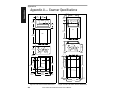
Appendix A — Scanner Specifications ................................................ A-2
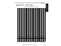
Appendix B — ASCII Table ................................................................. A-5
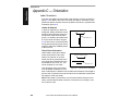
Appendix C — Orientation................................................................... A-6
Appendix D — Ground and Shield Considerations ............................. A-9
Appendix E — Defaulting the Scanner .............................................. A-10
Appendix F — Troubleshooting ......................................................... A-11
Appendix G — Bar Code Symbology ................................................ A-14
Appendix H — Interface Standards ................................................... A-15
Appendix I — Auxiliary Monitor ......................................................... A-16
Appendix J — Multidrop Communications ..............................................A-21
Appendix K — Glossary of Terms ..................................................... A-25
iv
MS-7100/7180 Industrial Scanner User’s Manual
List of Illustrations
Figure 1-1 System Diagram ....................................................................... 1-2
Figure 1-2 MS-7100/7180 Ranges and Scan Widths ................................. 1-4
Figure 1-3 MS-7180 Raster Height ............................................................ 1-5
Figure 1-4 Rear Panel ................................................................................ 1-8
Figure 1-5 Host Connector ......................................................................... 1-9
Figure 1-6 DTE Host Connections ........................................................... 1-10
Figure 1-7 Trigger Connection ................................................................. 1-11
Figure 1-8 Trigger Input Diagrams (untriggered) ..................................... 1-11
Figure 1-9 Power Connector .................................................................... 1-12
Figure 1-10 MS-7100 Orientation ............................................................. 1-14
Figure 1-11 MS-7180 Orientation ............................................................. 1-14
Figure 1-12 Bottom Mounting Holes of MS-7100 (not to scale) ............... 1-18
Figure 1-13 Bottom Mounting Holes of MS-7180 (not to scale) ................ 1-19
Figure 2-1 Configuration Program - Main Menu......................................... 2-2
Figure 2-2 Communications Menu Structure ............................................. 2-5
Figure 2-3 Operations Menu Structure ..................................................... 2-12
Figure 2-4 External Level Trigger Signals ................................................ 2-14
Figure 2-5 External Edge Trigger Signals ................................................ 2-14
Figure 2-6 Code Types Menu Structure ................................................... 2-22
Figure 2-7 User Outputs Menu Structure ................................................. 2-31
Figure 2-8 Raster Setup Menu Structure ................................................. 2-37
Figure 2-9 Raster Sweep Arc ................................................................... 2-37
Figure 4-1 Calibration Setup Menu ............................................................ 4-5
Figure A-1 Scanner Dimensions ................................................................A-2
Figure A-2 Scan Range ..............................................................................A-4
Figure A-3 Ladder Orientation ....................................................................A-6
Figure A-4 Picket Fence Orientation ..........................................................A-6
Figure A-5 Angled Picket Fence Orientation ..............................................A-7
Figure A-6 Detector Side Orientation .........................................................A-7
Figure A-7 Detector Right-Angle Orientation .............................................A-8
Figure A-8 Label Dimension .......................................................................A-8
Figure A-9 Raster Image ............................................................................A-8
Figure A-10 Grounding Diagram, Scanner-Host ........................................A-9
Figure A-11 Host Connector Default Pins ......................................................A-10
Figure A-12 Typical Multidrop Network ....................................................A-21
Figure A-13 Polling Sequence .................................................................A-22
Figure A-14 Select Sequence ..................................................................A-23
MS-7100/7180 Industrial Scanner User’s Manual
v
List of Tables
Table 1-1 MS-7100/7180 Read Range and Scan Widths.................................. 1-3
Table 1-2 Cable Distances ................................................................................ 1-8
Table 1-3 Host 28-pin Connector Pin Assignments .......................................... 1-9
Table 1-4 Trigger Connector Pin Assignments ............................................... 1-11
Table 1-5 Power Connector Pin Assignments ................................................ 1-12
Table 2-1 Symbology Identifier Option Values................................................ 2-23
Table 2-2 Raster Settings ............................................................................... 2-37
Table 3-1 Summary of Serial Configuration Commands .................................. 3-2
Table 3-2 Protocol Commands ......................................................................... 3-6
Table 5-1 Operational Commands .................................................................... 5-2
Table A-1 ASCII Table with Control Characters ............................................... A-5
Table A-2 Troubleshooting .............................................................................. A-11
Table A-3 Multidrop Address Characters ........................................................ A-24
About the MS-7100/7180 Scanner
The MS-7100 and the MS-7180 are fixed-mount industrial laser diode scanners enclosed in sealed cases. They employ brushless ball-bearing motors to
spin 14-sided mirrors at 1000 scans per second to read and decode barcode
labels at a wide variety of ranges. The MS-7180 includes a controllable stepper motor and raster mirror to create a scan pattern over a broad two-dimensional area.
About this Manual
This manual provides complete information on setting up, installing, and
configuring the MS-7100 and the MS-7180 industrial scanners.
Chapter 1 provides overall step-by-step instructions for setting up and installing
the scanner with specific “go to” references to other chapters and appendices.
Chapter 2 provides instructions for configuring the scanner by menu.
Chapter 3 provides instructions for configuring the scanner by serial command.
Chapter 4 provides instructions for using the Calibration Setup menu.
Chapter 5 describes the serial operational commands that can be sent from
the host.
For specifications, see appendix A. The appendices also include reference
tables as well as other useful information relating to bar coding and the
scanner.
Note: Bar code labels should meet minimum ANSI (American National
Standards Institute) standards as specified in ANSI Bar Code Print Quality
Guideline, X3.182-1990.
vi
MS-7100/7180 Industrial Scanner User’s Manual
Keystroke Entries
Keystrokes to be entered from your terminal are highlighted in bold, as in
<D>, including a < left angle bracket symbol (unless redefined by Command
Start Character command) and followed by a > right angle bracket symbol.
Approvals
• CDRH (Center for Devices and Radiological Health)
• TüV (Technischer überwachungs-Verein)
• CE
• cUL (Underwriters Laboratories, Inc.)
• FCC (Federal Communications Commission) Part 15, Class A
• This Class A digital apparatus meets all requirements of the Canadian
Interference-Causing Equipment Regulations.
Cet Appareil numerique de la classe A respecte toutes les exigences du
Reglement sur le material broilleur du Canada.
Warning and Caution Summary
Caution: This equipment has been tested and found to comply with
CISPR 22 and with the limits for a Class A digital device, pursuant to part
15 of the FCC Rules. These limits are designed to provide reasonable protection against harmful interference when the equipment is operated in a
commercial environment. This equipment generates, uses, and can radiate radio frequency energy, and, if not installed and used in accordance
with the instruction manual, may cause harmful interference to radio
communications. Operation of this equipment in a residential area is likely
to cause interference in which case the user will be required to correct the
interference at his or her own expense.
For connection to a Listed direct plug-in power unit marked Class II and
rated at 10 to 28 VDC unregulated power @10 watt maximum.
Safety Labels
Note: The safety labels will carry a CDRH Class II designation when
placed on an MS-7100 or MS-7180 with 670 nm visible light.
MS-7100/7180 Industrial Scanner User’s Manual
vii
WARNING
Use of controls, adjustments, or performance of procedures
other than those specified herein may result in hazardous laser
light radiation exposure. For connection to a listed direct plugin power unit market Class 2 and rated 5 VDC/200mA.
WARNING
There are no user serviceable parts in the MS-7100/MS-7180
scanner. Opening the scan head voids the Microscan Systems
warranty and could expose the user to laser diode power of up
to 5 mW.
WARNING
The laser beam can be harmful to eyesight. Avoid eye contact
with the laser beam. Never point the beam at other people, or
in a direction where people may be passing.
viii
MS-7100/7180 Industrial Scanner User’s Manual
The following label is found on the top of the MS-7100 and MS-7180:
10- 28VDC
.9 A M P M AX
1201 S W 7T H S T REET
RENT O N, W A 98055
1201 S W 7T H S T REET
RENT O N, W A 98055
LISTE D
U L 19 50
LISTE D
4K68
®
®
U L 19 50
CAUT IO N-L ASER LIGH T W H EN O PEN- DO NO T ST ARE INT O BEAM .
PRO DU C
CT
T C ON
ONFO
F OR
RM
M S T O USA D
DH
HH
HS
S2
21
1C
CFR
FR SU
SUBC
BC HAPT ER "J"
"J "
LA S E R
CCAAUU- T IO N
TIO O
LIG H T D
N ON
T S TA R E IN T O B E A M .
g e pr ü fte
Sic h e rh e it
TUV Rh e
einin la n d
la n d
4K68
®
1 AM P M AX
CAUT IO N-L ASER LIGH T W H EN O PEN- DO NO T ST ARE INT O BEAM .
PRO DU CT C ONFO R M S T O USA D HH S 21 C FR SU BC HAPT ER
"J "
LAS ER S T R AH LU
LUNG
NG N
NIC
IC HT
H T IN
I N DE N STR AHL BLIC K EN
LASER KLAS SE 2
95 nJ @ 38uS
1 m W MA X
MA X
C A U -T IO N
TI O N
VO
V
OR S
- IC H T
SIC HT
LA S E R S TR A
A H L U N G , W E N N A B D E C K -U N G
LA S E R LIG H T D O N O T S TA R E IN T O B E A M .
N FGN E T. N IC H T IN D E N S TR A H L B L IC K E N .
GEU
ÕF
E
E N 6 08 25 -1 : 19 9 4
C L A S S II L A S E R P R O D U C T
M AD E IN U .S.A.
g e pr ü fte
Sic h e rh e it
10- 28VDC
N FGN E T. N IC H T IN D E N S TR A H L B L IC K E N .
GG
E U
ÕF
E
67 0 nm L A S E R D IO D E
®
TUV Rh e
einin la n d
la n d
VO
V
OR S
- IC H T
LA S E R S TR A
A HS
E N N A B D E C K -U N G
L UINC
G ,H
WT
D IN V D E 08 37 Te i l 1: 19 94 -07
AVO ID
LA S E R LI G HT I S E M IT TE D
EXP OS UR E
F RO M T HI S A P E RTUR E
11 -110 009 -01
LAS ER S T R AH LU NG N IC HT
I N DE N STR AHL BLIC K EN
LASER KLAS SE 2
95 nJ @ 38uS
67 0 nm L A S E R D IO D E
1 mW
MA X
E N 6 08 25 -1 : 19 9 4
C L A S S II L A S E R P R O D U C T
M AD E IN U .S.A.
D IN V D E 08 37 Te i l 1: 19 94 -07
AVO ID
EXP OS UR E
LA S E R L IGH T
IS E M ITT E D
F R OM T HI S A P E RTUR E
MS-7100/7180 Industrial Scanner User’s Manual
11 -110 010 -01
ix
x
MS-7100/7180 Industrial Scanner User’s Manual
1
1–Setup and Inst.
Chapter
Setup and
Installation
Chapter Contents
Step 1 - Plan Scanning System ........................................................... 1-2
Step 2 - Verify Read Range ................................................................. 1-3
Step 3 - Estimate Scan Width .............................................................. 1-4
Step 4 - Determine Raster Height and Arc (7180) ............................... 1-5
Step 5 - Calculate Number of Scans.................................................... 1-6
Step 6 - Attach Cabling ........................................................................ 1-8
Step 7 - Configure Scanner .............................................................. 1-13
Step 8 - Position Scanner and Label ................................................. 1-14
Step 9 - Test and Autocalibrate ......................................................... 1-15
Step 10 - Adjust Other Scanning Parameters.................................... 1-16
Step 11 - Install Scanner.................................................................... 1-18
Operational Tips................................................................................. 1-19
This chapter provides step-by-step instruction for setting up and installing
the MS-7100 or MS-7180 scanner to obtain optimum read rates.
MS-7100/7180 Industrial Scanner User’s Manual
1-1
1–Setup and Inst.
Chapter 1
Setup and Installation
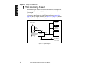
1 Plan Scanning System
Before installing the industrial scanner you should sketch out a diagram of
your scanning system, showing equipment, connector and cable types, and
cable lengths.
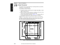
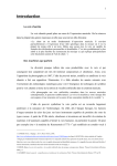
Figure 1-1 shows a possible scanning system setup. There are three cable
connectors on the scanner: the 28-pin host connector (see figure 1-5 on
page 1-9) the 9-pin trigger connector (see figure 1-7 on page 1-11) and the
9-pin power connector (see figure 1-9 on page 1-12).
O ptional
M onitor
Bar-coded
item flow
M S-5000
M ultidrop
Concentrator
O bject
Detector
9-pin
M S -7100/7100
Scanner
28-pin
Host
9-pin
Unregulated
10 to 28 V DC
pow er supply
Figure 1-1 System Diagram
1-2
MS-7100/7180 Industrial Scanner User’s Manual
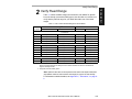
Verify Read Range
Table 1-1 shows readable ranges and maximum scan widths for specific
bar code density (narrow-bar-width) types. Use this table as a reference to
verify that the planned range for your label falls within one of the listed
ranges.
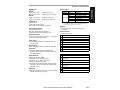
Table 1-1 MS-7100/7180 Read Range and Scan Widths
NarrowBar-Width
Read Rangea
MS-7100
Maximum Scan Width
MS-7180
Low Density
MS-7100
MS-7180
b
.020”
6” to 23” (15.2 to 58.4 cm)
4” to 20” (10.2 to 50.8 cm)
13” (33.0 cm)
12” (30.5 cm)
.030”
4” to 34” (10.2 to 86.4 cm)
2” to 32” (5.1 to 81.2 cm)
18” (45.7 cm)
16” (40.6 cm)
.040”
10” to 44” (25.4 to 112 cm)
8” to 42” (20.3 to 106.7 cm)
25” (63.5 cm)
22.5” (57.2 cm)
.050”
10” to 55” (25.4 to 140 cm)
8” to 50” (20.3 to 127 cm)
34” (86.4 cm)
31” (78.8 cm)
High Density
.010”
6” to 11” (15.2 to 27.9 cm)
4” to 8.5” (10.2 to 21.6 cm)
7.5” (19.1 cm)
7” (17.8 cm)
.015”
5” to 16” (12.7 to 40.6 cm)
3” to 13.5” (7.62 to 34.3 cm)
10.5” (26.7 cm)
9.5” (24.1 cm)
.020”
3” to 16” (7.6 to 40.6 cm)
1” to 14” (2.54 to 35.6 cm)
10.5” (26.7 cm)
9.5” (24.1 cm)
.030”
4” to 20” (10.2 to 50.8 cm)
2” to 18”(5.1 to 45.7 cm)
13.5” (34.3 cm)
13” (33 cm)
.040”
4” to 20” (10.2 to 50.8 cm)
4” to 18”(10.2 to 45.7 cm)
13.5” (34.3 cm)
13” (33 cm)
Ultra High Density
.005”
2” to 4.25” (5.1 to 10.8 cm)
1” to 3.5” (2.54 to 8.9 cm)
3.25” (8.3 cm)
2.25” (5.7 cm)
.0075”
2” to 5” (5.1 to 12.7 cm)
1” to 3.5” (2.54 to 8.9 cm)
3.75” (9.5 cm)
2.5” (6.4 cm)
a. Read range is the distance of the label from the scanner (measured from the front of the scanner
bezel) in which the label can be reliably read. The distance between the minimum and maximum
ranges is the depth of field.
b. FIS (Final Instruction Sheet) option.
Note: Optimum read rates can be expected at the center of the depth of field (halfway between minimum and maximum read range) for a given bar code density.
For information on label orientation, see Appendix C, “Orientation,” on page A6.
MS-7100/7180 Industrial Scanner User’s Manual
1-3
1–Setup and Inst.
2 Verify Read Range
1–Setup and Inst.
Chapter 1
Setup and Installation
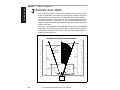
3 Estimate Scan Width
Scan width is that portion of the scan line in which a label can be read. For
ladder oriented labels, scan width must only be wide enough to fully cover
the label length, including quiet zones. With picket fence oriented labels,
scan width is a factor in determining the time during which the label can be
read. (See Appendix C, “Orientation,” on page A-6) The greater the scan
width, the longer a picket fence label will be in the scan range, and the more
scans it will receive.
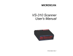
Use figure 1-2 to estimate the scan width that corresponds to the applicable
read range. For example, a picket fence label moving across the scan line
at 43 inches (109 cm) from the scanner will have a scan width of approximately 33 inches (83.8 cm).
Scan W idth
60
cm
150
60
140
55
in. 25
50
20
30
40
15
20
10
10
5
0
0
10
20
5
30
10
40
15
50
60
20
25
130
150
60
140
55
130
50
50
120
120
45
110
100
90
M S -7 18 0
R a n ge s
40
45
M S -7 10 0
R a n ge s
110
100
90
35
Low
Density
80
30
70
25
Low
Density
Scanner
40
25
20
50
40
15
10
20
High
Density
Scanner
Ultra High
Density
Scanner
Ultra High
Density
Scanner
High
Density
Scanner
5
20
15
30
10
20
10
0
0
in.
cm
R ange
5
0
0
in.
cm
R ange
Figure 1-2 MS-7100/7180 Ranges and Scan Widths
1-4
30
70
60
30
10
35
80
Scanner
60
50
40
MS-7100/7180 Industrial Scanner User’s Manual
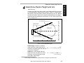
Determine Raster Height and Arc
(MS-7180 only)
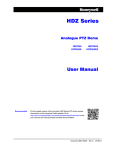
In setting up the MS-7180 raster scanner, raster height depends on the raster
arc and label distance (range) from the scanner. In figure 1-3 raster height
and raster arc are shown at their maximum with raster arc set to 45°. Both the
top offset and bottom offsets can be adjusted independently in one-degree
increments and the resulting arc can vary from 0° to 45°. (See “Raster Setup
Menu” on page 2-37.
T op offset set at 0°
(22.5° from perpendicular beam )
in .
cm
20
50
40
M axim um high
density range
30
10
20
M axim um low
density range
10
MS-7180
0
0
10
20
10
30
B ottom offset set at 0°
(22.5° from perpendicular beam )
40
R ange
in .
0
10
20
30
40
50
20
50
H eight
cm
0
10
20
30
40
50
60
70
80
90
100
110
120
Figure 1-3 MS-7180 Raster Height
Raster Height. If raster arc and label
∅
range are known, raster height can be
RH = ( 2 × ScanRange ) tan ----
2
derived by the following formula where Ø
1
is raster arc in degrees:
Raster Arc. If raster height and label
range are known, the raster arc can be
derived by using the following formula
where RH is raster height:
RH
∅ = 2 • atan ----------------------------------------
2 × ScanRange
1. Raster Height and Raster Arc formulas assume a straight-on symmetrical arc.
MS-7100/7180 Industrial Scanner User’s Manual
1-5
1–Setup and Inst.
4 Determine Raster Height and Arc
1–Setup and Inst.
Chapter 1
Setup and Installation
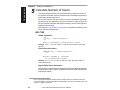
5 Calculate Number of Scans
To ensure reliable scanning, we recommend that you apply a minimum of
five scans to each label. Use the formulas below to calculate the number of
scans that your label will receive.
If the number of scans you derive from one of these calculations is less than
the minimum for your application, plug in the minimum number of scans and
solve for another parameter that might be changed, such as label speed or
scans per second (SPS).
See Appendix C, “Orientation,” on page A-6 for explanation of ladder, picket
fence, and label characteristics.
MS-7100
Ladder Calculation
LH
------- LS × SR – 3 = number of complete scans
1
Where LH = Label Height, LS = Label Speed, and SR = Scan Rate.
Example: If LH = 1, LS = 10, and SR = 1000, then the number of scans will
equal 97.
Picket Fence Calculation
SW – LL )
(------------------------- × SR – 3 = number of complete scans
LS
1
Where SW = Scan Width, LL = Label Length,
LS = Label Speed and SR = Scan Rate
Example: If LL = 2, LS = 10, SW = 8, and SR = 1000, then the number of
scans will equal 597.
Angled Picket Fence Calculation
The number of complete scans for angled picket fence is calculated the same
as that for picket fence, with the exception that the scan width is shortened in
proportion to scan tilt.
1. The -3 component is added to allow for AGC acquisition and for incomplete first and last
scans. This applies only if the calculation in the brackets is 3 or more. If it equals 2, then subtract only 1, giving 1 good scan.
1-6
MS-7100/7180 Industrial Scanner User’s Manual
Calculate Number of Scans
Ladder Calculation
Ladder scanning is rarely done with raster scanners and when it is, it is generally done with a stop and go label. In such a situation the number of scans is
equal to the scan rate times the number of seconds the label pauses under the
raster image (adjusted by the ratio of raster height to label height).
Picket Fence Calculation
For picket fence raster scanning, number of scans (NS) is arrived at by first
solving for sweeps per second (SPS).
Sweeps per Second (SPS) is the user-programmable number of raster
sweeps that transpire in a second. A sweep is defined as a single pass, up
or down, describing the raster image. Sweeps per second should generally
be as few as possible in order to maximize the number of scans applied to a
given label and to minimize wear on the raster parts and vibration to the
scanner.
The formula for finding Sweeps Per Second (SPS) is as follows:1
2 × LS
SPS = -------------------------( SW – LL )
Since SPS can only be entered into the software (see “Raster Setup Menu”
on page 2-37) as whole numbers, round off fractions of SPS to the next
higher number, for example enter 0.4 as 1 and 3.5 as 4.
Number of Scans (NS) be calculated by the following formula:2
LH × SR- – 3
NS = -----------------------RH × SPS
Example: If SW = 10, LL = 2, and LS = 2, then SPS will equal 0.5. Since 0.5
is less than one, we will assign a value of one in the Sweeps per Second
option as described in “Raster Setup Menu” on page 2-37 and in the NS formula which (with LH = 1, SR=400, RH = 10, and SPS = 1) calculates out to
37 complete scans.
1. The number 2 in the SPS formula is a constant that doubles the number of sweeps to
ensure that each label receives two full raster sweeps.
2. The -3 component is added to allow for AGC acquisition and for incomplete first and
last scans. This applies only if the calculation in the brackets is 3 or more. If it equals 2,
then subtract only 1, giving 1 good scan.
MS-7100/7180 Industrial Scanner User’s Manual
1-7
1–Setup and Inst.
MS-7180
1–Setup and Inst.
Chapter 1
Setup and Installation
6 Attach Cabling
28-pin host
connector
9-pin trigger
connector
9-pin p ower
conn ector
The scanner (figure 1-4) has three I/O
connectors on the rear panel which
accept circular, twist-lock, sealed
socket connectors. The center 9-pin
trigger connector is covered with a
removable dust cap.
A connector kit (P/N 98-200003-01) is
Figure 1-4 Rear Panel
included with your scanner. The kit contains a 9-pin socket connector kit (P/N 200002-01), a 28-pin cable connector kit
(P/N 98-200001-01), and related pins, clamps, screws, and dust seals.
Use the 28-pin connector kit (P/N 98-200001-01) as part of your host cable
assembly for connection with the 28-pin socket connector. (See table 1-3 on
page 1-9.)
Use the 9-pin socket connector (P/N 98-200002-01) to mate with the 9-pin
power connector (see “Power Connector” on page 1-12) or if desired, with
the 9-pin trigger connector (see “Trigger Connector” on page 1-11).
Note: The 9-pin cable connector kit (P/N 98-200002-01) will mate with either
the power connector or the trigger connector.
Under ideal conditions, maximum
cable lengths can meet the distances
shown in table 1-2. However, since
cable lengths and sizes are dictated
by local conditions such as wire size,
shielding, grounding, extraneous signal noise, etc., maximum cable distances will vary.
Table 1-2 Cable Distances
Cabling
Maximum Distance
RS-232 Scanner to Host
50’ (15.2 m)
RS-422 Scanner to Host
4000’ (1219 m)
RS-485 Multidrop Trunk
4000’ (1219 m)
RS-485 Multidrop Drop
10’ (3 m)
Several pins are repeated on different connectors. For example, you can
apply power optionally through the host or trigger connector, as well as the
power connector. You can also use pins 7 and 9 of either the trigger or
power connectors to route current through internal relay contacts which
open or close according to user-determined conditions (a noread, a match,
or a mismatch). The same pulse that drives this internal relay sends a TTL
pulse (high or low) to pin 6 on the host and pins 8 of both the trigger and
power connectors. If no data is decoded, a noread pulse is output to pin 6 of
the host connector. (See “Relay Settings” on page 2-32.)
1-8
MS-7100/7180 Industrial Scanner User’s Manual
Attach Cabling
1–Setup and Inst.
Host Connector.
The host connector is a 28-pin circular twist-lock
connector as shown in figure 1-5 (Amp CPC
series) that mates with a supplied 28-pin socket
connector (P/N 98-200001-01). It allows the
scanner to be connected to a host, a concentrator, or other communications device such as a
PLC (programmable logic controller), a monitor,
a PC, a relay, a diverter, an alarm, etc.
1
3
8
4
9
14
15
20
21
25
26
28
Figure 1-5 Host Connector
Pins 6, 8, and 25 (table 1-3) can be used to
drive a small relay to operate an alarm, diverter, etc. A pulse will be sent to
pin 8 at the occurance of any noread. Outputs to pins 6 and 25 are programmable (see “Relay Settings” on page 2-32). You can also control voltage level (“Output Polarity” on page 2-33) and duration of pulses (“Output
Pulse Width” on page 2-33) for all three pins (6, 8, and 25).
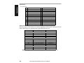
Table 1-3 Host 28-pin Connector Pin Assignments
Pin
Function
Pin
Function
1
Chassis ground
15
TXD + (RS-422/RS-485)a
2
Transmit data (RS-232)
16
TXD – (RS-422/RS-485)
3
Receive data (RS-232)
17
Reserved
4
Request to send (RS-232)b
18
Aux transmit data (RS-232)
5
Clear to send (RS-232)
19
Aux receive data (RS-232)
6
Relay--output #1c (see page 2-32)
20
Power ground
7
Signal ground (RS-232)
21
RXD + (RS-422/RS-485)
8
Noread Output (see page 2-17)c
22
RXD – (RS-422/RS-485)
9
+5 VDC out (100 mA max.)
23
Reservedb
10
Trigger input (0 VDC to +24 VDC)
24
Reservedb
11
+12 VDC out (50 mA max.)
25
TTL--output #2c (seepage 2-33)
12
–12 VDC out (20 mA max.)
26
Default config. (see page A-10)
13
Signal ground
27
New Master (see page 2-34)
14
Power input (10 to 28 VDC unreg.)
28
CPU master resetd
a. See your multidrop manual for multidrop cabling and termination requirements.
b. The default communications mode does not support pin 4 (RTS). If RTS and CTS are not
required by the host port, pins 4 and 5 should not be wired as the results will be unpredictable.
c. Source or sink 4 mA.
d. Bringing pin 28 to ground resets the CPU, clears all buffers, and restores all parameters that
have been saved to nonvolatile memory.
MS-7100/7180 Industrial Scanner User’s Manual
1-9
1–Setup and Inst.
Chapter 1
Setup and Installation
Figure 1-6 shows two minimum host connections for RS-232 communications using the supplied 28-pin socket connector shown on the left.
28-pin Connector to DB-25 DTE Connection
28-pin Connector to DE-9 DTE Connection
Scanner
Host
Scanne r
Ho st
T ra nsm it
2
2
Transmit
Transmit
2
2
Receive
Re ceive
3
3
Receive
Receive
3
3
Transmit
Signal G rn d
7
7
Signal Grnd
7
5
Signal Grnd
Signal Grnd
Figure 1-6 DTE Host Connections
Caution: Do not use a host cable with more wires connected than are required for
the application. The host connector of the scanner has many outputs that could
cause damage or interfere with normal operation if connected and improperly used.
Note: All Microscan products are configured as DTE at the host connector
when in RS-232 operation.
1-10
MS-7100/7180 Industrial Scanner User’s Manual
Attach Cabling
1–Setup and Inst.
Trigger Connector1
The scanner’s trigger connector (figure 1-7) is a
9-pin, circular, twist-lock type that mates with a
Microscan socket connector (P/N 98-200002-01) (not
supplied with the scanner). Trigger pin assignments
are listed in table 1-4.
A programmable pulse to internal relay contacts
will make or break connection between pins 7 and
9 for external use (up to 200 mA or 4 VA).
1
2
4
3
5
6
8
7
9
Figure 1-7 Trigger
Connection
Table 1-4 Trigger Connector Pin Assignments
Pin
1
2
3
4
5
6
7
8
9
Function
Power ground
Supply +12 VDC (out) @ 50 mA
Optional power input to the scanner (10 to 28 VDC unreg.)
Trigger Input from the object detector (3 to 24 VDC)
Power ground
Optional power input to the scanner (10 to 28 VDC unreg.)
Relay contact 1, (200 mA or 4 VA)
Relay--output #1 (source or sink 4 mA) (see table 1-3)
Relay contact 2 (200 mA or 4 VA)
Figure 1-8 shows examples of positive and negative external trigger inputs that
could be applied to the trigger port. (Shown in the untriggered state.)
Scanner Trigger
Connector
P ositiv e Trigger
N egativ e Trigger
1
Pwr Gnd
2
+1 2 VDC
3
10 to 28 V DC (in)
Trigger input
4
Trigger input
5
Pwr Gnd
5
Pwr Gnd
6
10 to 28 V DC (in)
6
10 to 28 V DC (in)
7
Relay Contact 1
7
Relay Contact 1
8
Noread Output
8
Noread Output
9
Relay Contact 2
9
Relay Contact 2
1
Pwr Gnd
2
+1 2 VD C
3
10 to 28 V DC (in)
4
+12 VDC (o ut)
+12 VDC (o ut)
NO
(Normally
Open Switch)
Triggering Device
Scanner Trigger
Connector
NC
(Normally
Closed S witch)
Triggering Device
Figure 1-8 Trigger Input Diagrams (untriggered)
1. Microscan offers an object detector for this connector (P/N 99-440001-03). Other trigger
sources can also be used. Mechanical switches, relays, etc.—which tend to be slow and
bouncy and produce multiple trigger signals—are not recommended unless equipped with
optical sensors or filtered transitions (optical, Hall effect, or DC solid state relays).
MS-7100/7180 Industrial Scanner User’s Manual
1-11
1–Setup and Inst.
Chapter 1
Setup and Installation
Power Connector
The power connector (figure 1-9) is a 9-pin, circular, twist-lock connector
(Amp CPC series) that mates with a supplied 9-pin socket connector
(P/N 98-200002-01). The pin assignments are listed in table 1-5.
Note: Trigger and host connectors can also supply power.
Pins 1, 3, 6, 7, 8, and 9 are identical to those of the trigger connector.
Pins 2 and 4 provide access to the scanner for the auxiliary RS-232 port
and are similar to pins 18 and 19 of the host 28-pin connector.
Pin 5 is internally connected to pin 1 of the host connector and to the external case to provide a path for electrostatic discharge or AC faults to pass
directly to ground. It is intended to be connected to a “safety ground” (also
known as “green-wire” or “third wire” ground). It is particularly useful in
installations where the case is not grounded through its mounting plate or
when this connection must be guaranteed even when the unit is
unmounted. This connection allows hazardous currents, such as electrostatic discharge or AC faults, to pass safely to ground instead of traveling
through the unit’s circuits or signal cabling.1
Table 1-5 Power Connector Pin Assignments
Pin
1
2
4
5
3
1
Power ground
2
Aux. transmit (RS-232)
3
Power input 10 to 28 VDC unreg. @ 9W
max. with less than 1 V p-p ripple
4
Aux. receive data (RS-232)
6
8
7
9
Figure 1-9 Power Connector
Function
5
Chassis ground
6
Power input 10 to 28 VDC unreg. @ 9W
max. with less than 1 V p-p ripple
7
Relay contact 1, (200 mA or 4 VA)
8
Relay--output #1 (source or sink 4 mA)
9
Relay contact 2 (200 mA or 4 VA)
1. Note that the path established by pin 1 of the host connector, which goes through the host
cable shield, is not effective for this purpose.
1-12
MS-7100/7180 Industrial Scanner User’s Manual
Configure Scanner
Configure Scanner
Settings for Communications, Operations, Code Types, and User Outputs
are stored in nonvolatile memory and can be configured from a host or auxiliary terminal by menu (Chapter 2, “Menu Configuration”) or by serial command (Chapter 3, “Serial Configuration”).
For explanations of configuration settings, see Chapter 2, “Menu Configuration.”
To establish communication you will need to match the host’s or auxiliary
terminal’s communication settings with your scanner’s settings (see “Communications Menu” on page 2-5). Also make certain that the code type
enabled in the scanner matches that of the label being used (see “Code
Types Menu” on page 2-22).
Hint: Enabling Autodiscrimination in the menus (or with the <P> command)
will allow your scanner to read all of the listed code types.
Communicating with an ASCII Terminal
The scanner communicates in full duplex, terminal mode with no handshake. It
also recognizes carriage returns and line feeds.
The host or ASCII terminal with must match the following default settings
before any communication can take place: 9600 Baud Rate, Seven Data Bits,
Even Parity, and One Stop Bit.
A PC or Macintosh computer can be used as an ASCII terminal if connected as
shown under “Host Connector” and running a communications program set to
the above defaults. See your computer manual for communication’s port
pinouts.
MS-7100/7180 Industrial Scanner User’s Manual
1-13
1–Setup and Inst.
7
1–Setup and Inst.
Chapter 1
Setup and Installation
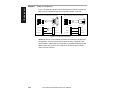
8 Position Scanner and Label
Before testing and calibrating, you will need to position the scanner and
label in a manner that matches as nearly as possible the actual conditions
of your application.
a. Position the scanner and label, taking care to avoid excessive tilt,
skew, or pitch.1
b. Pitch label slightly as shown in figures 1-10 and 1-11 to avoid specular
reflection, the return of direct, non-diffused light.2
Another way to avoid specular reflection is to skew the scanner
slightly in relation to the label.
Bar code
label
Ske w
axis
Skew axis
Bar code
label
Tilt
axis
Scan line
Tilt
axis
M S -7 180
S c anner
M S -7100
Scanner
Pitch
axis
Pitch
axis
Scan line
Figure 1-10 MS-7100 Orientation
Figure 1-11 MS-7180 Orientation
For more information, See Appendix C — “Orientation” on page A-6.
1. Maximum tilt is determined by label characteristics and number of scans required. Maximum
skew is ±40°; maximum pitch is ±50°.
2. The specular reflection zone is a narrow zone straight out from the scanner in which direct
reflected light from a label can distort the scanner’s ability to distinguish bars from spaces.
For the MS-7100 scanner, specular reflection is avoided by pitching labels at least 1.5 ° at
ranges from 0 to 20 inches (50.8 cm) from the scanner, and thereafter at diminishing angles,
for example, 0.75° at 40 inches (101.6 cm), and 0.5° at 60 inches (152 cm). For the MS-7180
raster scanner, specular reflection is avoided by pitching labels at least 5° from a line perpendicular to the raster mirror.
1-14
MS-7100/7180 Industrial Scanner User’s Manual
Test and Autocalibrate
If your proposed scanning range is not within the range specified in table
1-1 on page 1-3, go to step e.
If your proposed scanning range is within the range specified in table 1-1 on
page 1-3, test read rate by doing the following:
a. Position the label in front of a functioning scanner and launch the read
rate test with a <C> command from the host terminal. (See “Status
Commands” on page 5-5.)
b. Observe read rate. (Read rate is the percentage of scans decoded.)
c. Check depth-of-field (minimum/maximum range) by moving the label
closer and further relative to the scanner and noting the points where
the read rates fall below a level acceptable to your application.
Ideally, the label used in your application should pass through or
near the center of the depth-of-field.
d. Repeat steps a through c for other labels used in your application and
end the read rate test with a <J> command.
If the read rate is acceptable, go to Step 11, “Install Scanner,” on page 1-18.
If the read rate is not acceptable, continue with the following steps:
e. Do Autocalibration (see Chapter 4, “Calibration.”) and check Read
Rate within the Calibration program.
(Autocalibration optimizes the read rate by automatically cycling
through the gain and tracking settings and selecting the combination that achieves the highest read rate.)
f. If the results are not satisfactory after doing Autocalibration, go to Step
10, “Adjust Other Scanning Parameters,” on page 1-16.
Important: If, after Autocalibration or other adjustments you have changed the
read range or other parameter used in the number of scans formula, you
should recalculate the Number of scans (Step 5, “Calculate Number of Scans,”
on page 1-6).
Note: Variations between labels are common. For this reason, the greater
number of sample labels you test, the more likely you are to achieve optimum
read rates.
MS-7100/7180 Industrial Scanner User’s Manual
1-15
1–Setup and Inst.
9 Test and Autocalibrate
1–Setup and Inst.
Chapter 1
Setup and Installation
10 Adjust Other Scanning Parameters
Autocalibration (in step 9) is the preferred method of increasing read rate.
However, you might need to adjust other scanning parameters as well. This
section lists various adjustments (other than Autocalibration) that may
improve read rates.
After changing any of the parameters described in this section,
a. If applicable, recalculate the number of scans (Step 5, “Calculate
Number of Scans,” on page 1-6).
b. Repeat Step 9, “Test and Autocalibrate,” on page 1-15 (if adjusting
Gain or Tracking, omit sub-steps e and f).1
c. Compare the new read rate results with those obtained before
changes were made.
Scan Rate
Scan Rate is a function of motor speed and adjustable from within the Calibration Setup menu. The scanner is factory set at the upper rate of 1000
scans per second (sps), although it can be user adjusted to as low as 600. A
slower scan rate may allow greater label range and/or higher read rates, but
at the cost of fewer scans per label.
For example, if you have calculated that a label in your application will receive
98 scans with a scan rate of 1000 sps, then slowing the scan rate to 800 sps
will diminish the number of scans the label will receive to 78, a number that
should be well above your minimum.
To adjust scan rate (motor speed), send the <t> command to the scanner and follow
the screen cues. For more information, see “Motor Speed” on page 4-6.
Range
Adjusting the label’s range, if possible, is one of the quickest and most
effective ways to improve read rates. However, in some applications you
may need to select a less than optimum range, or one that is beyond the
fringes of the ranges listed in table 1-1 on page 1-3.
1. Changes in Gain and Tracking will be superceded by Autocalibration.
1-16
MS-7100/7180 Industrial Scanner User’s Manual
Adjust Other Scanning Parameters
Increasing scan width will increase the number of scans in a picket fence
oriented application. Scan width is linked with scan range (as shown in Step
3, “Estimate Scan Width,” on page 1-4) and changing one will usually
require a change in the other.
Label Speed
Applies to both picket fence and ladder oriented labels. If your application
allows it, label speed (the time in seconds in which a label is fully within the
scan width of the scanner) is an effective way to alter the number of scans.
Label Dimensions, Label Density, and Label Ratio
Not usually an option in most applications, but changes to label parameters
can affect number of scan calculations and possibly read rates.
If your application allows it, shortening the length of a picket fence label
means the label will be in the scan range longer and hence receive a
greater number of scans. Increasing the height of a ladder label means it
will receive more scans. Changing label density and/or ratio is another way
ranges, read rates, etc. can be altered.
Gain, Tracking, Bandwidth, and Clock Speed
These adjustments, typically made by technicians, are done from within the
Calibration Setup menu. Of these, Gain and Tracking are already adjusted
automatically by Autocalibration, and changes to Bandwidth and Clock
Speed will generally have a limited effect on read rates. See Chapter 4,
“Calibration.”
MS-7100/7180 Industrial Scanner User’s Manual
1-17
1–Setup and Inst.
Scan Width
1–Setup and Inst.
Chapter 1
Setup and Installation
11 Install Scanner
The scanner can be mounted directly to a mounting surface of your choice,
or indirectly, via a mounting plate.
To permanently mount the scanner:
a. Position the scanner in place devoid of sunlight, bright lights, or laser
light from other sources.
b. Before mounting, ensure that there is clearance at the rear of the
scanner for the connectors and cables being used.
c. Use the measurements provided in figure 1-12 to locate centers of
mounting holes and drill four 0.203 inch or four 6.7 mm holes.
Caution: Penetration depth of screws should not exceed 0.3 inch maximum.
Caution: To prevent twisting or distortion of the scanner housing, ensure that
the surface or bracket to which the scanner will be mounted is flat. If necessary, use only three mounting screws instead of four.
1.11"
(2.82)
5.3"
(13.59)
5.65"
(14.35)
3.25"
(8.26)
BO TTO M
M4 x 0.7
7.1 mm deep
Front
0.57"
(1.45)
4.41" (11.2)
0.57 in.
(1.45)
5.56" (14.13)
Figure 1-12 Bottom Mounting Holes of MS-7100 (not to scale)
1-18
MS-7100/7180 Industrial Scanner User’s Manual
Install Scanner
1–Setup and Inst.
1.11"
2.82 cm
3.25"
8.26 cm
8.72"
22.15 cm
8.42"
21.39 cm
M4 x 0.7
7.1 mm deep
0.57"
1.45 cm
4.41"
11.20 cm
0.57"
1.45 cm
5.56"
14.12 cm
Figure 1-13 Bottom Mounting Holes of MS-7180 (not to scale)
MS-7100/7180 Industrial Scanner User’s Manual
1-19
1–Setup and Inst.
Chapter 1
Setup and Installation
Operational Tips
Do:
• Check inputs (label speed, length, height, etc.) to ensure the desired
number of scans per label.
• Avoid excessive tilt, pitch, and skew of the bar code label.
• Check the label for readability by doing a read rate test. If there is any question about the label's readability, contact your Microscan representative.
• After changing any parameter that might affect read rate, repeat read rate
test, and if necessary, Autocalibration.
• Clean the laser window with a clean, dry cotton swab on a regular basis.
Do Not:
• Aim the scanner into direct light or sunlight.
• Aim the scanner into a photo detector or other light-emitting device.
• Obstruct the laser window with mounting hardware or other objects.
• Connect chassis of scanners and host to different ground potentials (see
“Ground and Shield Considerations” on page A-9).
• Operate the scanner in excessive temperature environments (see
“Appendix A — Scanner Specifications” on page A-2).
1-20
MS-7100/7180 Industrial Scanner User’s Manual
Chapter
2
Menu
Configuration
Entering the Menu Configuration Program .......................................... 2-2
Using the Menu Configuration Program .............................................. 2-2
Saving Menu Changes ........................................................................ 2-4
Loss of Communications ..................................................................... 2-4
Defining Special Characters ............................................................... 2-4
Communications Menu ........................................................................ 2-5
Operations Menu ............................................................................... 2-12
Code Types Menu.............................................................................. 2-22
User Outputs Menu............................................................................ 2-31
Raster Setup Menu ............................................................................ 2-37
This chapter describes how to configure the MS-7100/7180 scanner with on
screen menu commands from a host or auxiliary terminal.
All keystrokes are in bold typeface.
Default parameters in the menu structures are also in bold typeface.
All of these parameters, with the exception of Full Screens, can also be
changed by serial commands (see Chapter 3, “Serial Configuration”).
Communicating with an ASCII Terminal
The scanner communicates in full duplex, terminal mode with no handshake. It also recognizes carriage returns and line feeds.
The host or ASCII terminal must match the following default settings
before any communication can take place: 9600 Baud Rate, Seven
Data Bits, Even Parity, and One Stop Bit.
MS-7100/7180 Industrial Scanner User’s Manual
2-1
2–Menu Config.
Chapter Contents
Chapter 2
Menu Configuration
Entering the Menu Configuration Program
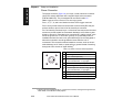
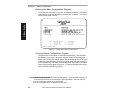
To see the Main menu (figure 2-1) from an ASCII terminal that is connected
to the scanner, enter the operational command <D> (enter the < > brackets
as well as the upper case D).1
2–Menu Config.
XX
Figure 2-1 Configuration Program - Main Menu2
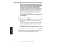
Using the Menu Configuration Program
The bottom line on the screen is called the command line. The command
line identifies your place in the menu program, shows current status and
allows you to review and change options. Use the designated keys3 to scroll
to and select the parameter you wish to change; press SP (space bar key)
to scroll ahead, B to scroll back, CR (carriage return key) to select, and M to
return to the previous higher level menu. To return to the Main menu at any
time, press ESC (escape key) and M.
1. Command start character by default is a left angle bracket, <. It may be redefined by menu or
serial command. However, the end character, a right angle bracket > cannot be changed.
2. Item 5, Raster Setup, applies only to the MS-7180.
3. The menu navigational keys are displayed in each menu.
2-2
MS-7100/7180 Industrial Scanner User’s Manual
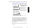
For example, to enable LRC (see figure 2-2 on page 2-5 and “Longitudinal
Redundancy Check” on page 2-9) use the following command line path:
From the Main menu, press CR at the
Communications prompt (this is the
first prompt displayed in the Menu
Configuration Program) to access the
Communications menu.
Communications —Host Protocol
Communications —> Host Port
Communications —> Aux Port
Since LRC is a subtopic of Host
Protocol, press CR to access the
Host Protocol parameters.
Host Protocol —> Protocol
Host Protocol —> Preamble = ^M
Host Protocol —> Preamble = Enabled
Host Protocol —>Postamble = ^M^J
Host Protocol —>Postamble = Disabled
Host Protocol —>LRC
Host Protocol —>Response Timeout
Host Protocol —> Intercharacter Delay
Protocol is the first parameter under
Host Protocol. Press SP until you
reach LRC, then press CR.
Host Protocol —> LRC = Disabled
Host Protocol —> LRC = Enabled
To enable LRC, press CR, SP, and
CR.
To view LRCs new status in the menu, press M to refresh the screen. To
return to the Main menu, press M again. You can make additional changes
within another menu before exiting the program. Simply follow the same
method of scrolling to and selecting each main topic, then its subtopics, until
you reach the parameter you want to change. Remember, to return to the
Main menu at any time, press ESC (Escape key) and M.
Some parameters are user defined, in which case they prompt you with an
arrow for data, such as:
At the prompt, redefine the parameter within the allowable range, and press
CR to enable.
MS-7100/7180 Industrial Scanner User’s Manual
2-3
2–Menu Config.
Main —> Communications
Main —> Operations
Main —> Code Types
Main —> User Outputs
Chapter 2
Menu Configuration
Saving Menu Changes
Press ESC (Escape key) to see the following on the command line:
Press M to return to the Main menu, or press E to exit the Menu Configuration program. If E is pressed, the following question will appear:
2–Menu Config.
Press N to exit without saving changes, or press Y to retain the current settings for power up. If Y is selected, a second beep will indicate the save has
been carried out.
Note: Choosing Y will save only current changes that were made in the Configuration menus and will not affect Calibration settings.
Loss of Communications
Defaulting might be necessary if communications between the scanner and
another device are interrupted or if using incompatible equipment (for
example, a terminal is set to communicate at 9600 baud, but the scanner is
configured at 38.4K baud). Communication can also be lost if an address
has been assigned to the scanner.
To reset parameters to default values, see Appendix E, “Defaulting the
Scanner,” on page A-10.
Defining Special Characters
To define any control character from the ASCII table: Press SP once, then
enter the control character by holding down the control key and simultaneously
pressing the desired character. For example to define a line feed, press SP,
then Control and J simultaneously. It is displayed as ^J on the command line
and as <LF> in the menu when the screen is refreshed.
To define CR as a character: Press SP, then CR. It is displayed as ^M on the
command line and as <CR> in the menu when the screen is refreshed.
To define a space as a character: Press SP twice. It is displayed as a blank
space in the menu when the screen is refreshed. While it appears that nothing has been assigned, the hex value 20 will be sent during data transmission.
To select NUL as the character: Press SP, then a 0 (zero). It is displayed as
<NUL> in the menu when the screen is refreshed.
2-4
MS-7100/7180 Industrial Scanner User’s Manual
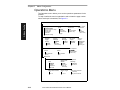
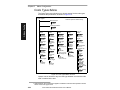
Communications Menu
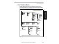
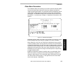
Communications Menu
The Communications menu (see figure 2-2) allows you to set the communication protocols between the scanner and the host.
Communications
–
Bold text represents default settings.
Host Protocol
Protocol
Preamble
–
RES
– Req
Address = ^A
– EOT
User Defined Multidrop
–
–
–
–
–
–
–
–
RES
Address = ^A
– Req
– EOT
LRC
–
–
–
– STX
– ETX
– ACK
– NAK
– STX
– ETX
– ACK
– NAK
Response Timeout
Disabled
Enabled
–
–
Postamble
Disabled
Enabled
12 ms
User Definable
(0 to 65,000)
–
–
Postamble
^M ^J
User
Definable
(ASCII
char.)
–
–
2–Menu Config.
–
–
–
Preamble
Point-to-Point
– ^M
Point-to-Point
– User
w/RTS/CTS
Definable
(ASCII char.)
Point-to-Point
w/XON/XOFF
Point-to-Point
w/RTS/CTS & XON/XOFF
Polling Mode D
Multidrop
– Address = 1
– User Definable
User Defined
–
Disabled
Enabled
Interchar Delay
–
–
0
User Definable (0 to 255)
Host Port
Baud Rate
–
–
–
–
9600
19.2K
38.4K
600
Stop Bits
Parity
– 1200
–
– 2400
–
– 4800
–
Even
Odd
None
–
–
Data Bits
One
Two
–
Parity
Stop Bits
–
Seven
Eight
RS-422
–
–
Disabled
Enabled
Aux Port
Aux Mode
–
–
–
–
–
Disabled
Transparent
Half Duplex
Full Duplex
Daisy Chain
Baud Rate
–
–
–
–
9600
19.2K
38.4K
600
– 1200
–
– 2400
–
– 4800
–
Even
Odd
None
–
–
One
Two
Data Bits
–
–
Seven
Eight
Figure 2-2 Communications Menu Structure
MS-7100/7180 Industrial Scanner User’s Manual
2-5
Chapter 2
Menu Configuration
2–Menu Config.
This menu can be regarded as three menus in one: a Host Protocol menu, a
Host Port communications menu, and an Aux Port communications menu.
To help visualize the menu organizational structure, see figure 2-2 on page
2-5. Note that the parameters (baud rate, parity, etc.) relate to the Host Port
and Aux Port.
Note: Changes in Communications parameters or assigning an address to the
scanner can cause loss of communications with the configuration terminal when
you exit the menu program (whether or not changes are saved for power-on).
Host Protocol Parameters
Protocol
Default: Point-to-Point
Options: Point-to-Point, Point-to-Point with RTS/CTS, Point-to-Point with
XON/XOFF, Point-to-Point with RTS/CTS and XON/XOFF, Polling
Mode D, Multidrop, User Defined, and User Defined Multidrop.
Protocols define the sequence and format in which information is transferred
between devices. Generally there are two basic protocol modes: unpolled
and polled. In unpolled mode (all of the Point-to-Point protocols), a device
sends information without any request from the host. In polled mode (Multidrop, Polling Mode D, and User Defined Multidrop), a device has an address
and waits for a request from the host before sending data.
2-6
Selecting:
Has this effect:
Point-to-Point
Has no address and sends data to the host (RS-232)
whenever it is available and without any request or
handshake from the host.
Point-to-Point with
RTS/CTS
(Request-to-Send/
Clear-to-Send)
Used only with RS-232. This is a simple handshaking
protocol that allows a device to initiate data transfers to
the host with an RTS (request-to-send) transmission. The
host, when ready, responds with a CTS (clear-to-send)
and the data is transmitted. RTS/CTS signals are
transmitted over two dedicated wires (pins 4 and 5) as
defined in the RS-232 standard.
Point-to-Point with
XON/XOFF
(Transmitter
On/Off)
Used with RS-232 or RS-422. The host can send a single
byte transmission command of start (XON) or stop
(XOFF). If an XOFF has been received from the host,
data will not be sent to the host until the host sends an
XON. During the XOFF phase, the host is free to carry on
other chores and accept data from other devices.
MS-7100/7180 Industrial Scanner User’s Manual
Communications Menu
Selecting:
Has this effect:
Point-to-Point with Used only with RS-232. It is a combination of Point-toRTS/CTS and
Point with RTS/CTS and Point-to-Point with XON/XOFF.
XON/XOFF
Like Point-to-Point, Polling Mode D requires a separate
connection to the host; but unlike Point-to-Point, it
requires an address and must wait for a poll from the host
before sending data. When in Polling Mode D, an address
of 1 is automatically displayed on the configuration
screen. However, during transmission, a 1C hex poll
address (FS) and a 1D hex select address (GS) are
substituted for the 1.
Multidropa
Similar to Polling Mode D except that a unique poll
address and select address are required for each
multidrop device, and only one host port connection is
needed for up to 50 devices. (For Multidrop poll and select
characters, see Table A-3, “Multidrop Address
Characters,” on page A-24.)
Requires a concentrator or controller using RS-485
communications. When Multidrop is selected, the protocol
characters for RES, REQ, etc. are assigned automatically.
(See Table A-3, “Multidrop Address Characters,” on page
A-24 for poll and select sequences.)
Note: Scanners
intended to link
up to a Microscan
MS-5000 multidrop concentrator
can only be configured in standard Multidrop
protocol.
User Defined
Note: A specific
ASCII character
must not be assigned more
than once.
Used only with RS-232 or RS-422. ASCII characters can
be assigned as an address and as protocol commands
(RES, REQ, EOT, STX, ETX, ACK, and NAK). User
Defined is necessary when a new protocol must be
defined to match a specific host protocol. When User
Defined is selected, the displayed protocol commands
match those of the previously selected protocol. User
Defined is considered to be in a polled mode only if an
address has been assigned. The address can be any
ASCII character from the ASCII in appendix B, except
NUL. b
MS-7100/7180 Industrial Scanner User’s Manual
2-7
2–Menu Config.
Polling Mode D
Chapter 2
Menu Configuration
Selecting:
Has this effect:
User Defined
Multidrop
Used when connecting to a concentrator or other device that
does not match standard Multidrop protocol.
Any single character (01 hex to 7E hex) in the ASCII table
can be assigned as the address character. The character
chosen is used as the poll character and the subsequent
ASCII character becomes the select character. For example,
if a ^A (01 hex) is selected as the address, ^B (02 hex)
becomes the select address that the host will use in sending
host select commands. (See Table A-3, “Multidrop Address
Characters,” on page A-24.)
2–Menu Config.
Note: A specific
ASCII character
must not be assigned more
than once.
a. Once the scanner is configured for Multidrop, a terminal connected to the auxiliary RS-232
pins or a default procedure must be used to access the configuration menus again (although
serial commands will continue to function).
b. For example a simple ACK/NAK protocol can be developed by first selecting Point-to-Point,
then User Defined, and then assigning characters to ACK and NAK commands. First scroll
to the following command:
HOST PROTOCOL --> PROTOCOL --> USER DEFINED--> ACK = -->
Enter a ^F by holding down the Control key while pressing the F key, and then press CR to
see the following:
HOST PROTOCOL --> PROTOCOL --> USER DEFINED --> ACK = ^F
The mnemonics ACK and NAK replace the default NULs in the menu.
Note: Definitions of commands in User Defined and User Defined Multidrop
must be duplicated in host applications to enable poll and select sequences to
execute correctly during transmission.
Typically, parameters in User Defined Multidrop are defined by first
enabling Multidrop, then enabling User Defined Multidrop. This pre-loads
Multidrop characters into the parameters. You then change individual characters to match the host or other requirements.
Preamble
Default:
^M (and a null). Corresponds to <CR><NUL> (carriage return/null)
displayed in the menu.
Options: Any ASCII character, including control characters. Control characters entered in the command line are displayed in the menu as mnemonic
characters. (See “Defining Special Characters” on page 2-4 and Table A-3,
“Multidrop Address Characters,” on page A-24.)
Allows you to define a one or two character data string that can be added to
the front of the decoded data. For example, defining a carriage return and
line feed would cause each decoded message to be displayed on its own
line.
If User Defined, Polling Mode D, or Multidrop is enabled, the Preamble and
Postamble characters are transmitted within the STX and ETX data block.
2-8
MS-7100/7180 Industrial Scanner User’s Manual
Communications Menu
Preamble (enable/disable)
Default: Disabled
Options: Disabled, Enabled (within any protocol)
Allows you to enable or disable the preamble character(s).
Postamble
Default:
Postamble (enable/disable)
Default: Disabled
Options: Disabled, Enabled (within any protocol)
Allows you to enable or disable the Postamble character(s).
Longitudinal Redundancy Check
Default: Disabled in unpolled mode; Enabled in polled mode
Options: Disabled, Enabled
An error-checking routine that verifies the accuracy of transmissions. It is
the exclusive OR of all characters following the SOM (start of message) up
to and including the EOM (end of message).
Response Timeout
Default: 12 ms.
Options: 0 to 65,000 ms. A zero (0) setting causes an indefinite wait.
Allows you to set the time the scanner will wait before timing out if ACK,
NAK, and ETX are enabled, and a host response is expected.
MS-7100/7180 Industrial Scanner User’s Manual
2-9
2–Menu Config.
^M^J. Corresponds to <CR><LF> (carriage return/line feed) displayed in the menu.
Options:Any ASCII character, including control characters. Control characters entered in the command line are displayed in the menu as mnemonic
characters. (See “Defining Special Characters” on page 2-4 and Table A-3,
“Multidrop Address Characters,” on page A-24.)
Allows you to define a one or two character data string that can be added
after the decoded message.
If User Defined, Polling Mode D, or Multidrop is enabled, the Preamble and
Postamble characters are transmitted within the STX and ETX data block.
Chapter 2
Menu Configuration
Intercharacter Delay
Default: 0 ms
Options: 0 to 255 ms. A zero (0) setting causes no delay between characters.
Allows you to set the time interval between individual characters transmitted
from the scanner to the host. A high setting will significantly slow down communications. For example, a 200 setting will result in a 1/5 second delay
between each character that is transmitted.
2–Menu Config.
Host Port Parameters
Allows you to set parameters for host port communications.
Baud Rate
Default: 9600
Options: 600, 1200, 2400, 4800, 9600, 19.2K, 38.4K
Allows you to set the number of bits transmitted per second.
Note: Due to timing considerations, polled modes require 2400 baud or faster.
Parity
Default: Even
Options: Even, Odd, None
Allows you to select an error detection routine in which one data bit in each
character is set to 1 or 0 so that the total number of 1 bits in the data field is
even or odd.
Stop Bits
Default: One
Options: One, Two
Allows you to select the last one or two bits in each character to indicate the
end of the character.
Data Bits
Default: Seven
Options: Seven, Eight
Allows you to establish the total number of bits in each character.
2-10
MS-7100/7180 Industrial Scanner User’s Manual
Communications Menu
RS-422
Aux Port Parameters
Allows you to set mode and communications parameters between the scanner and an auxiliary monitor. An auxiliary monitor can be used to configure
the menus, send data to the host, and display data transmissions originating from the host or scanner.
Note: Aux Port operates in RS-232 only. See Appendix I, “Auxiliary Monitor,” on
page A-16 for a full description of auxiliary port options.
Aux Mode
Default: Disabled
Options: Disabled, Transparent, Half Duplex, Full Duplex, Daisy Chain.
Aux Mode (auxiliary mode) allows you to select a communications mode for
auxiliary operations (see Appendix I, “Auxiliary Monitor,” on page A-16).
Other Aux Port Parameters
The other Aux Port parameters—Baud Rate, Parity, Stop Bits, and Data Bits—are
identical to the host port parameters and are changed in the same manner.
Note: The Aux Port baud rate should never exceed Host Port baud rate or auxiliary port data could be lost.
MS-7100/7180 Industrial Scanner User’s Manual
2-11
2–Menu Config.
Default: Disabled
Options: Disabled
Note: Used only in Point-to-Point protocol, and not with RTS/CTS.
Enabled
Whenever RS-422 is disabled, RS-232 is enabled in the background.
However, when Multidrop is enabled, the functioning protocol is RS-485
regardless of the displayed status of RS-422 in the menus. Before enabling
RS-422, first double-check that Multidrop is not enabled. (See “Protocol” on
page 2-6.
(See Appendix H, “Interface Standards,” on page A-15 for additional information on RS-422.)
Chapter 2
Menu Configuration
Operations Menu
The Operations menu allows you to set the operations parameters for the
scanner.
To help visualize the menu’s organization and to locate the page number
where each topic is described, see figure 2-3.
–
2–Menu Config.
Operations
Triggering Mode
–
–
–
–
–
–
End of Read
Cycle
Continuous Read
Continuous Read 1 Output
External Level
External Edge
Serial Data
Serial Data & Edge
External
Trigger
Polarity
–
–
–
–
–
–
Positive
Negative
–
–
–
–
–
Serial Trigger
Character
100
User Definable
(ASCII char.)
Bar Code
Output
Enabled
Disabled
–
–
Enabled
Disabled
–
–
1
User Definable
(1-6)
^]
User
Definable
(ASCII char.)
When to
Output
–
–
Number of
Labels
–
–
Noread
Message
NOREAD
User
Definable
(ASCII Chars)
1
User Definable
(1-31)
TImeout in
10 ms incs.
Timeout
New Trigger
Timeout & New
Trigger
Noread
Message
Good Decode
Reads
–
–
Bold text represents default settings.
As Soon As
Possible
End Of
Read Cycle
Field Separator
–
–
, (comma)
User Definable
(ASCII char.)
Matchcode
Match Code
Type
–
–
–
–
Match Code
Master
Disabled
Enabled
Sequential
Wild Card
–
–
Match Start Position
–
–
0
0 to 31
(blank)
User entry
(up to 15
characters)
Match Length
–
–
Sequential
Matching
–
–
Increment
Decrement
Wild Card Character
1
1 to 31
–
–
* (asterisk)
any ASCII character
Figure 2-3 Operations Menu Structure
2-12
MS-7100/7180 Industrial Scanner User’s Manual
Operations Menu
Triggering Mode
Default: Continuous Read
Options: Continuous Read, Continuous Read 1 Output, External Level,
External Edge, Serial Data, Serial Data & External Edge
Allows you to establish the type of trigger event that initiates or ends the
read cycle. (See “End of Read Cycle” on page 2-14.)
Has this effect:
Continuous Read
Trigger input options are disabled and the scanner is always
in the read cycle. Bar code data is decoded, and label
information is transmitted repeatedly, as long as the label is
in the read range of the scanner. When To Output options
have no affect on Continuous Read. Continuous Read is
useful in testing label or scanner functions.
Note: If Continuous
Read is enabled with
Match Code, the
scanner defaults to
Continuous Read 1
Output mode.
Continuous Read 1
Outputa
NOTE: Enabling
Continuous Read 1
Output when Number of Labels (page
page 2-18,) is set to
any number greater than one, will
cause Number of
Labels to default
back to one.
Label data is immediately transmitted with Timeout enabled
for End Of Read Cycle. If the label doesn't change, the
scanner will repeat the output at the end of each
subsequent timeout period. For example, if Timeout were
set to one second, the scanner would output the label data
immediately, and then repeat the output at intervals of one
second, for as long as the label continued to be scanned.
With Timeout disabled (that is, End Of Read Cycle set to
New Trigger), the scanner will output the current label data
immediately, but output it only once. A new label appearing
at any time in the scan range will produce a new read output
as long as the new label is not identical to the previous
label.
External Level
Allows a read cycle to be initiated by a trigger signal from an
object detector when an object appears within the detector’s
range. The read cycle endures until the object moves out of
the detector’s range (figure 2-4 on page 2-14) unless a
timeout occurs and Timeout is enabled for End of Read
Cycle.b
External Edge
As with Level, Edge allows a read cycle to be initiated by a
trigger signal from an object detector when it detects the
appearance of an object (rising edge). But unlike Level
mode, the removal of an object (falling edge) does not end
the read cycle. With Edge enabled, the read cycle ends with
a good read output, a timeout, or a new trigger (figure 2-5
on page 2-14).
MS-7100/7180 Industrial Scanner User’s Manual
2-13
2–Menu Config.
Selecting:
Chapter 2
Menu Configuration
Selecting:
Has this effect:
Serial Data
The scanner accepts an ASCII character from the host or
controlling device as a trigger to start a read cycle.
Serial Data &
External Edge
The scanner accepts either an external trigger or a serial
ASCII command to start a read cycle.
2–Menu Config.
a. Continuous Read 1 Output will allow an output regardless of how Good Decode Reads is set.
b. Level and Edge apply to the active logic state (positive or negative) that exists while the object is in
a read cycle, between the rising edge (the appearance of an object) and falling edge (disappearance of the object).
1
First trigger
An object, moving in
front of the detector
beam, causes the first
trigger (rising edge
trigger) signal to be sent
to the decoder, initiating
the read cycle.
1
Object
detector
Object
detector
2
1
Object
detector
Second trigger
The same object, moving
out of the detector's
beam, causes a second
trigger (falling edge
trigger) signal to be sent
to the decoder, ending
the read cycle.
Figure 2-4 External Level Trigger Signals
Object
detector
First rising edge trigger
Object #1, moving in
front of the detector
beam, causes the first
trigger (rising edge
trigger) signal to be sent
to the decoder, initiating
the read cycle.
Subsequent rising edge
trigger
Object #2, moving in front
of the detector's beam,
causes a second trigger
(rising edge trigger) signal
to be sent to the decoder.
This signal initiates a new
read cycle and ends the
previous read cycle
provided that New Trigger
or Timeout and New Trigger
is enabled and a good read
or timeout has not already
occurred.
Figure 2-5 External Edge Trigger Signals
End of Read Cycle
Default: Timeout
Options: Timeout, New Trigger, Timeout & New Trigger
Allows you to choose the conditions that will end the read cycle. The read
cycle is the time during which the scanner will receive and process label
2-14
MS-7100/7180 Industrial Scanner User’s Manual
Operations Menu
data. When the Triggering Mode option is set in an External or Serial mode
of operation, the trigger event initiates the read cycle.
Note: When operating in Continuous Read or Continuous Read 1 Output, the
scanner is always in the read cycle.
Has this effect:
Timeout
Can end the read cycle after a specified period of time,
and if no label has been read, causes a noread message,
if enabled, to be transmitted.
With either External Edge, Serial Data, or Serial Data & Edge
enabled, a timeout ends the read cycle.
With External Level enabled, the read cycle does not end
until the falling edge trigger occurs, and the next read
cycle does not begin until the next rising edge trigger.
With Continuous Read 1 Output enabled, a timeout
initiates a new read cycle and allows the same label to be
read again.
New Trigger
Ends the read cycle at the occurrence of a new trigger
event, and if no label has been read, causes a noread
message, if enabled, to be transmitted at the occurrence
of the new trigger event.
With either External Edge, Serial Data, or Serial Data &
Edge enabled, an edge or serial trigger ends a read cycle
and initiates the next read cycle.
With External Level enabled, a falling edge trigger ends a
read cycle. However, the next read cycle does not begin
until the occurrence of the next rising edge trigger.
Timeout &
New Trigger
Ends the read cycle after a specified period of time or at
the occurrence of new trigger event, and if no label has
been read, causes a noread message, if enabled, to be
transmitted.
With either External Edge, Serial Data, or Serial Data &
Edge enabled, a timeout, or an edge or serial trigger,
whichever comes first, ends the read cycle. An edge or
serial trigger also initiates a new read cycle.
With External Level enabled, the read cycle does not end
until the occurrence of a falling edge, and the next read
cycle does not begin until the next rising edge trigger.
MS-7100/7180 Industrial Scanner User’s Manual
2-15
2–Menu Config.
Selecting:
Chapter 2
Menu Configuration
Timeout (in 10 ms incs)
100 (one second). Corresponds to 1000 ms displayed in the
menu.
Options: 0 to 65535. Divide the number entered on the command line by
100 for time in seconds.
Note: Timeout or Timeout & New Trigger under End of Read Cycle (page 2-14,)
must be enabled for Timeout (in 10 ms incs) to take effect.
Allows you to define the duration of the timeout period.
2–Menu Config.
Default:
Serial Trigger Character
Default: ^]. Corresponds to <GS > displayed in the menu.
Options:A single ASCII character, including control characters, except a NUL
(00H), an existing host command character,1 or an on-line protocol character.
Control characters entered on the command line are displayed in the menu as
mnemonic characters. See “Defining Special Characters” on page 2-4 and
Table A-1, “ASCII Table with Control Characters,” on page A-5.
Note: Serial Data (page 2-14) or Serial Data & Edge (page 2-14) must be
enabled for Serial Trigger Character to take effect. “N/A” is displayed in the
menu when all other triggering modes are enabled.
Allows you to define a single ASCII character as the host serial trigger character that initiates the read cycle. The serial trigger is considered an on-line
host command and requires the same command format as all host commands (that is, to be entered within the < > brackets).
External Trigger Polarity
Default: Positive
Options: Positive, Negative
Note: External Level (page 2-13) External Edge (page 2-13) or Serial Data &
Edge (page 2-14) must be enabled for External Trigger Polarity to take effect.
“N/A” is displayed in the menu when all other triggering modes are enabled.
Allows you to determine whether a positive or negative transition will initiate
the read cycle.
Note: If using the Microscan object detector (P/N 99-440001-03), use positive
trigger polarity.
1. For example, assigning an upper case D would nullify the <D> (Enter Menu Configuration)
command. For a list of operational commands used by the scanner, see table 5-1 on page 5-2.
2-16
MS-7100/7180 Industrial Scanner User’s Manual
Operations Menu
Noread Message
Default: NOREAD
Options: Up to seven ASCII characters
Allows you to define any combination of ASCII characters (except a NUL)
up to seven characters as the noread message.
The noread message, if enabled and if no bar code label has been decoded,
will be transmitted to the host at a timeout or the end of a read cycle.
Default: Enabled
Options: Enabled, Disabled
Note: If Noread Output is enabled, the noread message will only output if Bar
Code Output (page 2-17) is also enabled.
Allows you to enable or disable the noread message.
Bar Code Output
Default: Enabled
Options: Enabled, Disabled
Allows you to choose whether or not to output label data or a noread to the
host. When disabled, a label is decoded and the read cycle transpires as
usual, but neither label data nor the noread message is transmitted to the
host. Scanner counters are updated, and the current number of good reads
or noreads can be obtained via operational commands.
When to Output
Default: As Soon As Possible
Options: As Soon As Possible, End of Read Cycle
Allows you to choose when bar code data is sent to the host.
Selecting:
Has this effect:
As Soon As Possible Causes bar code data (good reads) to be transmitted
immediately upon a good decode.
End of Read Cycle
Causes bar code data output to be delayed until the
end of the read cycle.
MS-7100/7180 Industrial Scanner User’s Manual
2-17
2–Menu Config.
Noread Message (enable/disable)
Chapter 2
Menu Configuration
Good Decode Reads
2–Menu Config.
Default: 1
Options: 1 to 31
Allows you to select the number of good reads (from 1 to 31) required per
label before a good decode output.
Note: Be sure that the value set is within the determined scan rate for the scanning setup so that the scanner is capable of scanning a label the required number of times.
Number of Labels
Default: 1
Options: 1 to 6
Note: If Number of Labels is set to any number greater than one while Match Code
or Continuous Read 1 Output is enabled, Number of Labels will default back to one.
Allows you to choose the number of different labels that the scanner will read
during a single trigger event. The labels can be a mix of any enabled bar code
symbologies and more than one label can be decoded per scan line.
The following conditions apply:
1. Each label must be different to be read.
2. The maximum number of characters in any one label is 51, unless Fixed
Code Length is enabled in which case the maximum length is 31.
3. The maximum number of characters in a single scan line is 102.
4. The maximum number of characters for all labels scanned is 255,
including preamble, postamble, and all spaces and commas.
5. All noread messages are posted at the end of the data string.
6. If more than one label is within the scan beam at the same time, label
data may not be displayed in the order of appearance.
Field Separator
Default: , (comma)
Options: Any available ASCII character, except NUL.
Allows you to choose the separator character to be inserted between labels.
2-18
MS-7100/7180 Industrial Scanner User’s Manual
Operations Menu
Match Code
2. Sending serial command <G> enables the next good read to be the
master label.
3. Sending serial command <)XXXX)> downloads data as master label.
“Master Label Entry” on page 2-21 shows the sequence of operation (and reference) for setting up and entering master labels. See also “New Master Pin”
on page 2-34.
Match Code Type
Default: Disabled
Options: Disabled, Enabled, Wild Card, and Sequential
When not disabled, allows you to enter a master label into the scanner's RAM
to be compared with subsequently scanned labels. The results of this comparison determine the scanner’s data and relay outputs, if enabled.
The following conditions apply:
1. A triggered mode must be enabled for Match Code Type to take effect.
2. Not disabling Match Code Type when Number of Labels is set to any
number greater than one will cause Number of Labels to default back
to one.
3. If you wish to send a pulse on a Good Read, Match Code Type must
be disabled.
MS-7100/7180 Industrial Scanner User’s Manual
2-19
2–Menu Config.
Default: Disabled
Options: Disabled, Match Code Type, Match Code Master, Sequential Matching, Match Start Position, Match Length, Wild Card Character
Note: A triggered mode (see“Triggering Mode” on page 2-13) must be enabled
for Match Code to take effect.
Note: If Match Code is enabled with Continuous Read, the scanner defaults to
Continuous Read 1 Output mode, and the label data must change before the
scanner will output data again, unless a timeout, if enabled, occurs.
Note: Enabling Match Code when Number of Labels is set to any number
greater than one, will cause Number of Labels to default back to one.
Allows you to enter a master label into the scanner's memory to be compared with subsequently scanned labels.
With Match Code enabled, a master label can be entered in three ways:
1. With New Master Pin enabled (page 2-34,) toggling pin 27 to ground
(pin 7) enables the next good read to be the master label.
Chapter 2
Menu Configuration
Disabled
Disabled has no effect on operations.
Enabled
Instructs the scanner to compare labels or portions of labels with the master label.
2–Menu Config.
Sequential
Instructs the scanner to compare labels or portions of labels for sequential
numbers in ascending or descending order.
There are four ways to load a master (see “Master Label Entry” on page 221). In every case sequencing occurs after each match. See “Match Code”
on page 3-10 for special noread and mismatch sequences.
Wild Card
Allows you to enter user defined wild card characters in the master label.
For example, with wild card defined as the default asterisk, entering URGENT**
as your master label will result in matches for URGENT, URGENT1, and
URGENT12 but not for URGENT123.
As in the above example, when wild cards are appended to the end of the
master label, labels of variable lengths can result in matches. However, wild
cards in the beginning or center of a label (e.g., UR**NT) do not allow for
variable label lengths.
Match Code Master
Default: (blank)
Options: Displays current master and accepts user entry up to 31 characters.
Allows you to edit an existing master or type in a new master label from your
keyboard.
Sequential Matching
Default: Increment
Options: Increment, Decrement
Defines the order (ascending or descending) in which labels will be compared when Match Code Type is set to Sequential.
2-20
MS-7100/7180 Industrial Scanner User’s Manual
Operations Menu
Match Start Position
Match Length
Default: 1
Options: 1 to 31
Defines the length of the character string that will be compared with that of
the master label when Match Code Type is set to Enabled or Sequential
and Match Start position is set to 1 or greater. For example, If Match Length
is set to 6 in a 10 character label, and Match Start Position is set for 2, only
the 2nd through 7th characters (from left to right) will be compared.
Wild Card Character
Default: * (asterisk)
Options: Any ASCII character
Allows you to define the wild card character that can be used when defining
a master label.
Master Label Entry
With Match Code Type set to Enabled, Sequential, or Wild Card, a master
label can be entered in four ways:
1. By typing in from the keyboard at the command line of the Operations
menu under Match Code Master.
2. With New Master Pin enabled (see page 2-34), toggling scanner pin 12 to
ground (or by momentarily pressing the New Master button on the IB105) will save the next label read as the master label.
3. Sending serial command <G> allows the next label read to be the master label.
4. Sending a serial command in the format <)XXXX)> downloads data as
the master label.
MS-7100/7180 Industrial Scanner User’s Manual
2-21
2–Menu Config.
Default: 0
Options: 0 to 31
Match Start Position must be set to 1 or greater to enable this feature.
Defines the first character in the label (from left to right) that will be compared with those of the master label when Match Code Type is set to
Enabled or Sequential. For example, if you set Match Start Position to 3, the
first 2 characters read in the label will be ignored and only the 3rd and subsequent characters to the right will be compared, up to the number of characters specified by Match Length.
Chapter 2
Menu Configuration
Code Types Menu
The Code Types menu allows you to choose among five bar code types
and define their parameters, as shown in figure 2-61.
Code Types
–
Bold text represents default settings.
2–Menu Config.
Narrow Margins
– Disabled
– Enabled
Symbology Identifier
– Disabled
– Enabled
Code 39
- Status
– Enabled
– Disabled
- Check Digit
– Disabled
– Enabled
- Check Digit
Output
– Disabled
– Enabled
- Large
Interchar Gap
– Disabled
– Enabled
- Fixed Code
Length
– Disabled
– Enabled
- Code Length
– 10
– User
Definable
(1 to 31)
Codabar
- Status
– Disabled
– Enabled
- Start & Stop
Match
– Enabled
– Disabled
- Start & Stop
Output
– Enabled
– Disabled
- Large
Interchar Gap
– Disabled
– Enabled
- Fixed Code
Length
– Disabled
– Enabled
- Code Length
– 10
– User
Definable
(1 to 31)
UPC
I 2 of 5
- Status
- Status
– Disabled
– Disabled
– Enabled
– Enabled
- EAN
- Check Digit
– Disabled
– Disabled
– Enabled
– Enabled
- Supplementals
- Check Digit
Output
– Disabled
– Enabled
– Disabled
– Required
– Enabled
- Code Length #1 - Separator
– Enabled
– 10
– Disabled
– User
Definable
- Separator
(even, 0 to 30)
– , (comma)
- Code Length #2 – User
Definable
– 6
(ASCII char.)
– User
Definable
(even, 0 to 30)
Code 128
- Status
– Disabled
– Enabled
- Fixed Code
Length
– Disabled
– Enabled
- Code Length
– 10
– User Definable
(1 to 31)
- UCC/EAN-128
–
Status
– Disabled
– Enabled
– Required
–
Format
–
Ap. Rec. Sep.
–
Ap. Rec. Sep.
– Standard
– Ap.
Rec.
– Disabled
– Enabled
–,
(comma)
Definable
– User
–
Ap. Rec. Brackets
–
Ap. Rec. Padding
– Disabled
– Enabled
– Disabled
– Enabled
Figure 2-6 Code Types Menu Structure
Options can be defined for any bar code type whether or not the bar code
itself is enabled at the time.
1. Options listed in the command line appear in a different order than those posted in the first
column of the Code Types menu
2-22
MS-7100/7180 Industrial Scanner User’s Manual
Code Types Menu
Narrow Margins
Default: Disabled
Options: Disabled, Enabled
Allows the scanner to read bar codes with quiet zones less than 10 times the
narrow-bar-width. Quiet zone is a term used to describe the minimum space at
the leading and trailing ends of a label. Each quiet zone can be as small as five
times the narrow bar element when Narrow Margins is enabled.
Default: Disabled
Options: Disabled, Enabled
When enabled, the scanner reads and outputs a three character prefix:
1. ] (close bracket character) indicating the presence of a symbology ID
2. A, F, I, E, or C
A = Code 39; F = Codabar; I = I 2 of 5; E = UPC/EAN; C = Code 128
3. A single number indicating the status of the check digit character (table 2-1):
If check digit is not enabled, the output is 0 (col. 1). If check digit
and check digit output are enabled, the output is as shown in column 2. If check digit is enabled, but output is disabled (col. 3), the
output is as shown in col. 4, which is the sum of col. 2 and col. 3.
Table 2-1 Symbology Identifier Option Values
Column 1
No check
character
Code 39
0
Column 2
Column 3
Check digit and
Check digit
output enabled output disabled
1
Column 4
Sum of Column 2 and 3
(2)
3
Codabar
0
2
(4)
6
I 2 of 5
0
1
(2)
3
UPC/EAN
Code 128
Always zero, do not follow AIM spec.
Example 1: For Code 39, if check digit and check digit output are
both enabled, a 1 will be output; but if check digit output is disabled, a 3 (the sum of column 2 and column 3) will be output.
Example 2: For Codabar, if check digit and check digit output are
both enabled, a 2 will be output; but if check digit output is disabled, a 6 (the sum of 2 and 4) will be output.
MS-7100/7180 Industrial Scanner User’s Manual
2-23
2–Menu Config.
Symbology ID
Chapter 2
Menu Configuration
Code 39
Status
Default: Enabled
Options: Enabled, Disabled
Check Digit
2–Menu Config.
Default: Disabled
Options: Disabled, Enabled
Code 39 is self-checking and does not normally require a check digit. However, for additional data integrity, a Modulus 43 check digit can be added to
the bar code message. With Check Digit and an External or Serial trigger
option enabled (see “Triggering Mode” on page 2-13) an invalid check digit
calculation will cause a noread message to be transmitted at the end of the
read cycle.
Check Digit Output
Default: Disabled
Options: Disabled, Enabled
When enabled, the check digit character is sent along with the label data.
When disabled, label data is sent without the check digit.
Large Intercharacter Gap
Default: Disabled
Options: Disabled, Enabled
Allows the scanner to read labels with gaps between bar code characters
exceeding three times the narrow element width.
Fixed Code Length
Default: Disabled
Options: Disabled, Enabled
Used to increase data integrity by ensuring that only label length will be accepted.
Code Length
Default: 10
Options: 1 to 31
Note: Fixed Code Length (page 2-24) must be enabled for Code Length to take
effect.
2-24
MS-7100/7180 Industrial Scanner User’s Manual
Code Types Menu
Allows you to specify the exact number of characters that the scanner will
recognize. Any code not having the prescribed length will be ignored by the
scanner. Available only when Fixed Code Length is enabled.
Codabar
Status
2–Menu Config.
Default: Disabled
Options: Disabled, Enabled
Start & Stop Match
Default: Enabled
Options: Enabled, Disabled
Requires the Codabar start and stop characters (a, b, c, or d) to match
before a valid read can occur.
Start & Stop Output
Default: Enabled
Options: Enabled, Disabled
Allows the start and stop characters to be transmitted with bar code data.
Large Intercharacter Gap
Default: Disabled
Options: Disabled, Enabled
Allows the scanner to read labels with gaps between bar code characters exceeding
three times the narrow element width.
Fixed Code Length
Default: Disabled
Options: Disabled, Enabled
Used to increase data integrity by ensuring that only label length will be accepted.
Code Length
Default: 10
Options: 1 to 31
Allows you to specify the exact number of characters that the scanner will
recognize. Any code not having the prescribed length will be ignored by the
scanner. Available only when Fixed Code Length is enabled.
MS-7100/7180 Industrial Scanner User’s Manual
2-25
Chapter 2
Menu Configuration
Interleaved 2 of 5
Status
2–Menu Config.
Default: Disabled
Options: Disabled, Enabled
Because I 2 of 5 is a continuous code, it is prone to substitution errors.
Hence, a code length must be defined and a bar code label containing an
even number of digits must be used. It is also recommended that a Modulus
10 check digit be used to ensure the best possible data integrity.
Check Digit
Default: Disabled
Options: Disabled, Enabled
I 2 of 5 uses a Modulus 10 check digit.
Check Digit Output
Default: Disabled
Options: Disabled, Enabled
When enabled, the check digit character is sent along with the label data.
When disabled, label data is sent without the check digit.
Code Length #1
Default: 10
Options: 0 to 30, even (If you enter an odd number the scanner will use the
next lower number.)
With I 2 of 5, two code lengths can be defined. When using only one label
length in an application, we recommend setting Code Length #2 to 0 to
ensure data integrity. If a check digit is used, it must be included in the code
length count.
Code Length #2
Default: 6
Options: 0 to 30, even. (If you enter an odd number the scanner will use
the next lower number.)
If using a second label, you may also specify a zero or any even code
length from 2 to 30. If not using a second label, set Code Length #2 to 0 to
ensure data integrity.
2-26
MS-7100/7180 Industrial Scanner User’s Manual
Code Types Menu
UPC
Status
Default: Disabled
Options: Disabled, Enabled
When enabled, the scanner will read UPC version A and UPC version E only.
EAN
Supplementals
Default: Disabled
Options: Disabled, Enabled, Required
Note: Narrow Margins must be enabled if the gap between the standard code and
the supplemental code is between 5:1 and 10:1 (in relation to narrow-bar-width).
Allows the scanner to read supplemental bar code data that has been
appended to the standard UPC or EAN codes. When in Required mode,
supplemental and bar code label data are treated as a single label, and
supplemental data must be found or a noread will result.
When set to Enabled, the scanner treats the supplemental data and the bar
code label as separate labels.
Separator
Default: Enabled
Options: Enabled, Disabled
Allows you to insert a character between the standard UPC or EAN code
and the supplemental code.
Separator (character)
Default: , (comma)
Options: Any ASCII character
Allows you to change the separator character from a comma to a new
value.
MS-7100/7180 Industrial Scanner User’s Manual
2-27
2–Menu Config.
Default: Disabled
Options: Disabled, Enabled
Note: UPC must also be enabled for EAN to take effect.
When EAN is enabled, the scanner will read UPC version A, UPC version
E, EAN 13, and EAN 8. It will also append a leading zero to UPC version A
label information and transmit 13 digits. If you do not want to transmit 13
digits when reading UPC version A labels, disable EAN.
Chapter 2
Menu Configuration
Code 128
Status
Default: Disabled
Options: Disabled, Enabled
Fixed Code Length
2–Menu Config.
Default: Disabled
Options: Disabled, Enabled
Allows you to increase data integrity by ensuring that only one label length
will be accepted.
Code Length
Default: 10
Options: 1 to 31
Allows you to specify the exact number of characters that the scanner recognizes. The scanner ignores any label not having the specified length.
UCC/EAN-128
Status
Default: Disabled
Options: Disabled, Enabled, Required
A subset of Code 128, with extended features.
Note: Code 128 must be Enabled for UCC/EAN-128 to function.
With Enabled selected, both Code 128 and UCC/EAN-128 labels are
decoded.
With Required selected, only UCC/EAN-128 labels are decoded.
Format
Default: Standard
Options: Standard, Ap. Rec. (Application Record)
Allows you to choose between Standard UCC/EAN-128 and Application
Record formats.
With Standard enabled, UCC/EAN-128 labels are interpreted and output in
standard UCC/EAN-128 format.
Application Record is a user-definable variation of UCC/EAN-128 that does
the following:1
• Separates Application Identifier fields.
2-28
MS-7100/7180 Industrial Scanner User’s Manual
Code Types Menu
Application Record Separator
Default: Disabled
Options: Disabled, Enabled
Note: Application Record must be enabled under Format before this parameter
can take effect.
When enabled, a separator character is inserted between data fields.
Application Record Separator
Default: , (comma)
Options: User Defined
Note: Application Record must be enabled under Format before this parameter
can take effect.
Allows you to define an ASCII character as a separator.
Application Record Brackets
Default: Disabled
Options: Disabled, Enabled
Note: Application Record must be enabled under Format before this parameter
can take effect.
When enabled, brackets ( ) are added to enclose application identifiers.
1. When Number of Labels (page 2-18,) is set to greater than One, Application Record Padding
must be disabled. If Application Record Padding is enabled, label data will be output in the
Standard Format.
MS-7100/7180 Industrial Scanner User’s Manual
2-29
2–Menu Config.
• Pads variable length fields (unless disabled) with 0’s until the maximum
length is reached (except for the last field of the label).
• Passes each Application Identifier and its data field onto the application processing software.
• Allows you to add and define separators between data fields, enclose
Application Identifier’s in brackets, and disable padding.
Note: If an illegal Application Record format is detected, then the scanner will
process it as a “noread” message, except that it will output it as a “Bad Format”
in place of the noread.
Chapter 2
Menu Configuration
Application Record Padding
Default: Enabled
Options: Enabled, Disabled
Note: Application Record must be enabled under Format before this parameter
can take effect.
Note: When Number of Labels (page 2-18,) is set for more than One, Application Record Padding must be disabled. If Application Record Padding is
enabled, output will automatically default to Standard Format.
2–Menu Config.
Padding is the insertion of zeros to make up the maximum length of a variable application identifier field, except for the last field which does not
require padding.
When enabled, padding is included.
When disabled, padding is omitted.
Note: Padding is never added to fixed length fields or to the last data field of a
label. Enabling or disabling padding will have no effect on these.
2-30
MS-7100/7180 Industrial Scanner User’s Manual
User Outputs Menu
User Outputs Menu
The User Outputs menu allows you to configure the scanner’s output.
To help visualize the menu’s organization and to locate the page number
where each topic is described, see figure 2-7.
User Outputs
Beeper Volume
Relay Settings
Level 4
– Level 5
– Level 1
– Level 2
– Level 3
On Good
– On Noread
– Disabled
Bold text represents default settings.
–
–
Relay-Output #1
TTL-Output #2
Mismatch or
Noread
– Good Match
– Mismatch
– Noread
Mismatch
or Noread
– Good Match
– Mismatch
– Noread
–
–
Output Pulse Width*
Output Polarity
Positive
– Negative
–
–
Full Screens
Enabled
– Disabled
–
Command Start
Character
<
– User Definable
(ASCII Char.)
–
New Master Pin
–
Laser On/Off
Reverse Video
Disabled
– Enabled
Disabled
– Enabled
–
–
K Command Options
50 ms
User Definable
(0 to 255)
–
–
Disabled
Enabled
Partial Output
Echo K Cmd
Disabled
– Enabled
–
Beep on K
Disabled
– Enabled
–
Ctrl Char Output
Ctrl
– Hex
–
Status
–
–
Disabled
Enabled
Start Position
–
–
1
1 to 31
Partial Length
–
–
31
1 to 31
* The number entered on the command line represents 1/10 actual value in milliseconds.
Figure 2-7 User Outputs Menu Structure
MS-7100/7180 Industrial Scanner User’s Manual
2-31
2–Menu Config.
Beeper Status
–
Chapter 2
Menu Configuration
Beeper Status
2–Menu Config.
Default: On Good
Options: On Good, On Noread, Disabled
On Good is enabled by default. The options are On Good, On Noread, or
Disabled.
Note: The beeper interrupts operations for approximately 100 ms. We recommend that you disable the beeper in high-speed Multidrop operations since the
time delay can cause labels to be missed.
Beeper Volume
Default: Level 4
Options: Level 4, Level 5, Level 1, Level 2, Level 3
Relay Settings
Relay--Output #1
Default: Mismatch or Noread
Options: Mismatch or Noread, Good Match, Mismatch, Noread
Allows you to determine the conditions under which internal relay contacts
(pins 7 and 9 of the trigger and power connector) will be opened or closed.
The TTL level output that drives this internal relay is also available on pin 6
of the host connector and pin 8 of both the trigger and power connectors.1
Selecting:
Has this effect:
Mismatch
or Noread
Sends a pulse when the label's data does not match that of
the master label, or the label is not decoded before the end
of the read cycle.
Good Match
Sends a pulse when the decoded label matches the master
label (or any good read if match code is disabled).
Mismatch
Sends a pulse when the label’s data does not match that of
the master label.
Noread
Sends a pulse when the label’s data is not decoded before
the end of the read cycle.
Note: If Good Match is enabled but Match Code is not enabled (see “Match
Code” on page 2-19) then any occurance of a good read will cause a pulse to
be output and mismatches will be ignored.
1. Pins 6 and 8 can source or sink 4 mA maximum. Pins 7 and 9 can conduct up to 200 mA or
4VA.
2-32
MS-7100/7180 Industrial Scanner User’s Manual
User Outputs Menu
TTL--Output #2
Default: Mismatch or Noread
Options: Mismatch or Noread, Good Match, Mismatch, Noread
Allows you to determine the conditions under which a user-programmable TTL
pulse will be output (high or low depending on polarity) to pin 25 of the host
connector.
Has this effect:
Mismatch
or Noread
Sends a pulse when the label's data does not match that of
the master label, or the label is not decoded before the end
of the read cycle.
Good Match
Sends a pulse when the decoded label matches the master
label (or any good read if match code is disabled).
Mismatch
Sends a pulse when the label’s data does not match that of
the master label.
Noread
Sends a pulse when the label’s data is not decoded before
the end of the read cycle.
Note: If Good Match is enabled but Match Code is not enabled (see “Match
Code” on page 2-19) then any occurance of a good read will cause a pulse to
be output and mismatches will be ignored.
Output Polarity
Default: Positive
Options: Positive, Negative
Allows you to choose between positive and negative logic signals to pins 6,
8, and 25 on the host connector, to pin 8 on both the trigger and power connectors, and to the internal relay contacts that open or close a switch
between pins 7 and 9 on both the trigger and power connectors.
When Output Polarity is set to Positive, the switch between pins 7 and 9 on
the power and trigger connectors will be normally open (unless closed by an
output pulse). Conversely, if Output Polarity is set to Negative, pins 7 and 9
of the power and trigger connectors will be normally closed.
Output Pulse Width
Default: 5 (.05 seconds). Corresponds to 50 ms displayed in the menu.
Options: 0 to 255 (0 to 2.55 seconds). Divide the number entered on the
command line by 100 for time in seconds.
Allows you to set the duration of the output pulses to pins 6, 8, and 25 on
the 28-pin connector, to pin 8 on both the trigger and power connectors,
MS-7100/7180 Industrial Scanner User’s Manual
2-33
2–Menu Config.
Selecting:
Chapter 2
Menu Configuration
and to internal relay contacts that open or close a switch between pins 7
and 9 on both the trigger and power connectors.
Caution: Too long of a pulse width can cause missed labels, especially if Output Pulse Width exceeds End of Read Cycle Timeout (see page 2-14,).
Full Screens
2–Menu Config.
Default: Enabled
Options: Enabled, Disabled
Allows you to display either the full menu screen or just the command line.
When Full Screens is disabled, only the command line will be displayed.
New Master Pin
Default: Disabled
Options: Disabled, Enabled
Note: Match Code (page 2-19,) and a triggered mode (page 2-13,) must be
enabled for New Master Pin to take effect.
Allows you to momentarily connect pin 27 to ground (pin 7) in order to clear
any existing master label information from memory and to record the next
good read as the new master label information.
Laser On/Off
Default: Disabled
Options: Disabled, Enabled
Note: A serial or external trigger (see “Triggering Mode” on page 2-13) must be
enabled for Laser On/Off to take effect.
When enabled, the laser is ON only during the read cycle. When disabled,
the laser operates continuously.
Note: Laser On/Off does not relate to the <H> (Enable Laser Scanning) and <I>
(Disable Laser Scanning) operational commands discussed under “Device Control Commands” on page 5-3.
Reverse Video
Default: Disabled
Options: Disabled, Enabled
When enabled, the scanner will read bar code labels with bars that are
lighter in color than their corresponding backgrounds.
2-34
MS-7100/7180 Industrial Scanner User’s Manual
User Outputs Menu
Command Start Character
Default: <
Options: Any ASCII character (except a NUL).
Allows you to define a new ASCII start character in a serial command.
K Command Options
Note: It is important to note that if a command with multiple fields is processed,
some of the fields may have been processed properly following an “invalid”
command. These changes will be in the string echoed back so that the user will
know what did or did not change.
Beep on K Command
Default: Disabled
Options: Disabled, Enabled
When enabled, the scanner beeps once whenever a K command is entered to indicate that the command was accepted and processed. If an invalid command is
entered, the scanner beeps 5 times to indicate an invalid entry. However, this does
not necessarily mean that all data fields have been entered incorrectly. Only one
bad field needs to be found in order to activate the 5 beep response.
Control Character Output
Default: Ctrl
Options: Ctrl, Hex
Determines response to an Echo K or status request command. When set to
CTRL, ASCII control character output includes a control character as shown in
the “Ctrl” column of Table A-B, “ASCII Table,” on page A-5. When set to Hex,
the output is the actual character.
MS-7100/7180 Industrial Scanner User’s Manual
2-35
2–Menu Config.
Echo K Command
Default: Disabled
Options: Disabled, Enabled
When enabled, serial configuration commands (“K” commands) will be processed
and the new string for that command will be echoed back to the host. If an invalid
command is sent to the host, the scanner will echo back the current setting of that
command. For example, if the current Noread Message is “NOREAD” and
<Kk1,NONSENSE> is entered, the scanner will echo back: <Kk1,NOREAD>. In
this example the attempted entry “NONSENSE” exceeds the maximum allowable
seven characters. Therefore it is rejected and the current NOREAD message is
echoed back and remains the Noread Message.
Chapter 2
Menu Configuration
Partial Output
2–Menu Config.
Status
Default: Disabled
Options: Disabled, Enabled
When enabled, allows you to pre-select portions of labels to be transmitted
by the scanner.
In multilabel mode, partial output is performed on each separate label. For
example, if Start Position is set to 3 and Partial Length is set to 5, the following labels are transmitted as follows:
1234567890 as
“34567”
1234 as
“34”
1234,abcde as
“34,cde” (two labels with separator)
12
as
““
Start Position
Default: 1
Options: 1 to 63
Allows you to determine the first character from the beginning of a label to
transmit.
Partial Length
Default: 63
Options: 1 to 63
Allows you to determine the number of characters to be transmitted.
2-36
MS-7100/7180 Industrial Scanner User’s Manual
Raster Setup Menu
Raster Setup Menu
The Raster Setup menu allows you to set the top and bottom of the raster
arc in degrees, control the number of raster sweeps per second, and enable
Raster On/Off. Figure 2-8 shows the structure of this menu.
Raster Setup
Top Offset
In Degrees
Enabled
– Disabled
–
–
–
0
User
Definable
(0 to 45)
Bottom
Offset In
Degrees
45
– User
Definable
(0 to 45)
–
Sweeps Per
Second
–
–
Raster
On/Off
14
User
Definable
(0 to 135)
–
–
2–Menu Config.
Status
Enabled
Disabled
Figure 2-8 Raster Setup Menu Structure
For additional information on raster setup, see Step 4, “Determine Raster
Height and Arc,” on page 1-5 and Step 5, “Calculate Number of Scans,” on
page 1-6.
Status
Default: Enabled
Options: Enabled, Disabled
Top Offset in Degrees
Default: 0 (degrees)
Options: 0 to 45 (in one-degree
increments)
MS-7180 Raster
Scanner
Top Offset= 0°
Raster
Arc
Bottom Offset = 45°
Figure 2-9 Raster Sweep Arc
Table 2-2 Raster Settings
Raster
Arc
1°
5°
10°
15°
20°
25°
30°
35°
40°
45°
MS-7100/7180 Industrial Scanner User’s Manual
Sweeps per Second
Minimum
Maximum
1
1
1
1
1
1
1
1
1
1
135
75
45
35
29
23
21
19
17
14
2-37
Chapter 2
Menu Configuration
Note: Top Offset must always be less than the bottom offset or the resulting arc
will be 0°.
Bottom Offset in Degrees
Default: 0 (degrees)
Options: 0 to 45 (in one-degree increments)
Sweeps Per Second
2–Menu Config.
Default: 14 (sweeps per second)
Options: 0 to 135
Allows you to control the raster motor speed. A “sweep” is defined as a single pass, up or down, creating the raster image.
Table 2-2, “Raster Settings,” on page 2-37 shows minimum and maximum
possible sweep speeds at selected raster arcs. The minimum speed at any
arc is always one sweep per second (SPS). Note that the maximum sweep
speed for the raster arc that you have chosen will not exceed the default,
even if you enter a higher speed.
To maximize the number of scans a label will receive, it is recommended
that as few as possible sweeps per second be selected. However, to ensure
that the minimum required scan lines cross the bar code label, it is essential
that at least two full sweeps occur during the time it takes for the label to
pass through the readable scan width area.
For example, if the label is readable in the read range for only 1/10th of a
second, then the number of sweeps per second should be at least 20. If
readable for only 1 second, then sweeps per second should be at least 2.
(To see a formula for calculating sweeps per second, see Step 5, “Calculate
Number of Scans,” on page 1-6.)
Raster On/Off
Default: Disabled
Options:Disabled, Enabled
Note: Laser On/Off must be enabled (KC1) for Raster On/Off to take effect.
When enabled, the raster will shut off (or turn on) approximately 1.9 ms
after a change in the state of the laser. Since this time delay may interfere
with certain applications—for example where a trigger has occurred and a
read is expected—you can disable Raster On/Off and the raster motor will
remain on at all times.
2-38
MS-7100/7180 Industrial Scanner User’s Manual
Chapter
3
Serial
Configuration
Chapter Contents
This chapter describes how to configure the MS-7100/7180 scanner by
serial commands from a host.1
All of the configuration parameters that can be changed in the menus with
the exception of Full Screens, as described in Chapter 2, “Menu Configuration,” can also be changed by serial configuration commands.
All of the serial configuration parameters, with the exception of Trigger Filter
Timing Value, also appear in the menus.
1. The scanner communicates in full duplex, terminal mode with no handshake. It also recognizes carriage
returns and line feeds. The host or ASCII terminal with must match the following default settings before
any communication can take place: 9600 Baud Rate, Seven Data Bits, Even Parity, and One Stop Bit. If
communicating from an auxiliary terminal via the auxiliary port (pins18 and 19 of the 28 pin connector, the
serial command <D> (Enter Menu Configuration Program) is the only command that the scanner will recognize.
MS-7100/7180 Industrial Scanner User’s Manual
3-1
3–Serial Config.
Summary of Serial Configuration Commands...................................... 3-2
Communications Commands............................................................... 3-5
Operations Commands ........................................................................ 3-9
Code Type Commands ...................................................................... 3-12
User Outputs Commands .................................................................. 3-15
Raster Setup Commands................................................................... 3-17
Chapter 3
Serial Configuration
Summary of Serial Configuration Commands
Table 3-1 Summary of Serial Configuration Commands
Function
(Not in
menu)
Communications
Cmd
Command Title
KF
Trigger Filter Timing Value
Kf
Host Protocol
<Kfprotocol,data,...>
Kd
Preamble
<Kdstatus,ASCII characters>
Ke
Postamble
<Kestatus,ASCII characters>
<Kcstatus>
Kc
LRC
KA
Host Response Timeout
<KAnumber>
KB
Intercharacter Delay
<KBnumber>
Ka
Host Port
<Kabaud,parity,stop bits,data bits>
Kb
RS-422
<Kbstatus>
Ky
Aux Port
<Kymode,baud,parity,stop bits,data bits>
3–Serial Config.
KG?1 Comm. Status Request
<KG?1>
Triggering Mode
<Kgmode>
Kh
End of Read Cycle
<Khmode,time>
Ki
Serial Trigger Character
<Kicharacter>
Kj
External Trigger Polarity
<Kjmode>
Kk
Noread Message
<Kkstatus,message>
Kg
Operations
Format
<KF?> (returns current value in milliseconds)
<KFtime in 10 ms increments>
Bar Code Output
<Klstatus,when to output>
Km
Kl
Good Decode Reads
<Kmnumber>
Kn
Match Code
KL
Number of Labels
<Kntype,sequential matching,match start position,match
KG?2 Operations Status Request
Code Type
<KLnumber of labels,separator character>
<KG?2>
Ko
Narrow Margins/
Symbology ID
<Konarrow margins status,symbology ID status>
Kp
Code 39
<Kpstatus,check digit,check digit output,large interchar
gap,fixed length,length>
Kq
Codabar
<Kqstatus,S/S match,S/S output,large interchar gap,fixed
length,length>
Kr
Interleaved 2 of 5
<Krstatus,check digit,check digit output, length 1,length 2>
Ks
UPC/EAN
<Ksstatus,EAN status,supplementals status,
separator status,separator char.>
Kt
Code 128
<Ktstatus,fixed length,length,UCC/EAN status,format,ap.
rec. separator,ap. rec. separator,ap. rec. brackets,ap. rec.
padding>
KG?3 Code Type Status Request
3-2
length,wild card character,sequence on noread,sequence
on every mismatch>
<KG?3>
MS-7100/7180 Industrial Scanner User’s Manual
Summary of Serial Configuration Commands
Table 3-1 Summary of Serial Configuration Commands
Function
User
Outputs
Cmd
Command Title
Format
Ku
Beeper
<Kustatus,volume>
Kv
Relay Settings
<Kvrelay--output #1 setting,TTL--output #2 setting>
Kz
New Master Pin
<Kzstatus>
KC
Laser On/Off
<KCstatus>
KD
Reverse Video
<KDstatus>
Kw
Output Polarity
<Kwmode>
Kx
Output Pulse Width
<Kxnumber>
KE
Command Start Character
<KEASCII character>
KG
Serial Verification
<KSecho K command,beep on K command,control char-
KY
Partial Ouput
<KYstatus,start position,partial length>
acter output>
KG?4 User Output Status Request <KG?4>
Raster
KR
Raster Setup
<KRstatus,top offset,bottom offset,motor speed,raster on/off>
Format: <Kparameterdata,data,...etc.><initializing command>
Where:
• Less than < and greater than > symbols are included as part of the commands.
• “parameter,” as used here, are those character(s) that precede the data.
• the “initializing command” <Z> is sent after configuration is complete to
reset and save for power up. If you want to reset without saving for power
up, send the command alone.1
For example, the following command enables UPC: <Ks1>.
When using serial configuration commands, note also the following conventions:
• Parameters and data are “case sensitive.” That is, characters must be
entered as upper or lower case, as specified.
• All data fields (except the last) must be followed by a comma (without a space).
• If there is no change in a given field, then commas can be entered alone,
or with the existing data (for example, <Ka,,,0> or <Ka4,1,0,0>).
1. Commands that effect Communications are unique. See “Initializing serial configuration commands that
effect communications” on page 3-4 for definitions and examples.
MS-7100/7180 Industrial Scanner User’s Manual
3-3
3–Serial Config.
Serial Configuration Command Format
Chapter 3
Serial Configuration
• All fields preceding the modified field must be included. For example, in
the RS-232 port, to change Data Bits to Eight without changing any other
field, enter either: <Ka,,,1> or <Ka4,1,0,1>.
• All fields following the modified field can be left out. For example, in the
RS-232 port, to change Baud Rate to 4800, enter <Ka3>.
(See examples on following pages.)
Initializing serial configuration commands that effect communications
3–Serial Config.
For a serial configuration command that effects communications to be
implemented, you need to follow it with one of the operational commands
below:
• <A> To reset but not save changes for power-up
• <Z> To reset and save changes for power-up
For example, to change Baud Rate and reset without saving changes for
power-up, enter <Ka3><A>.
To change Baud Rate and reset, saving the changes to non-volatile RAM,
enter <Ka3><Z>.
Concatenating Serial Commands
Commands can also be concatenated (added together) to a maximum of 64
characters in a single string or data block. Additional data blocks of 64 or
less characters can be sent provided there is at least a 10 ms pause
between blocks.1
For example, the following command, <Kc1><KA24><Ko1><A> enables LRC,
sets the Host Protocol Response Timeout to 24 ms, enables Narrow Margins and
resets the data buffers (without saving the changes for power-on).
Loss of Communications
Assigning a multidrop address to a scanner or making changes to communications parameters such as Baud Rate, Parity, Stop Bits, LRC, etc. without corresponding changes in linked device(s) can result in the loss of menu
access. If this should occur, try gaining access to the scanner by entering a
<D> command from an auxiliary terminal via the auxiliary RS-232 port. If
neither of these methods is available, try defaulting the scanner. See
“Appendix E — Defaulting the Scanner” on page A-10.
1. Data in excess of 64 characters will reset the buffer, causing the first 64 characters of the string to be lost
and indicator #1 to illuminate red 2 seconds after the end of each read cycle, until the scanner’s memory
is reset.
3-4
MS-7100/7180 Industrial Scanner User’s Manual
Communications Commands
Communications Commands
Host Protocol
If selecting one of the options from 0 to 4 (Point-to-Point, Point-to-Point with
RTS/CTS, Point-to-Point with XON/XOFF, Point-to-Point with XON/XOFF
and RTS/CTS, or Polling Mode D), use this format:
Format: <Kfprotocol>
protocol:
0 = Point-to-Point
1 = Point-to-Point with RTS/CTS
2 = Point-to-Point with XON/XOFF
3 = Point-to-Point
with XON/XOFF and RTS/CTS
4 = Polling Mode D
5 = Multidrop
(requires address)
6 = User Defined
7 = User Defined Multidrop
Example: To change the Protocol to Polling Mode D, enter <Kf4>.
Format: <Kf5protocol,address>
protocol:
5 = Multidrop
address:
Any number from
1 to 50
Example: To change the Protocol to Multidrop with an address of 33, enter
<Kf5,33>.
If selecting User Defined (6) or User Defined Multidrop (7), you complete
the format by either choosing new parameters or concatenating unchanged
data fields (separate by commas).
For User Defined, you first select Point-to-Point <Kf0> and then User
Defined <Kf6...>. For user Defined Multidrop, you first select Multidrop
<Kf5>, then User Defined Multidrop <Kf7...>.
MS-7100/7180 Industrial Scanner User’s Manual
3-5
3–Serial Config.
If selecting Multidrop (5), you must define an address and append it to the
command string.
Chapter 3
Serial Configuration
Format: <Kfprotocol,RES,address,REQ,EOT,STX,ETX,ACK,NAK>
RES
Protocol:
6 = User Defined
Address
7 = User Defined Multidrop EOT
STX
ETX
ACK
NAK
Example: To select an unpolled ACK/NAK User Defined protocol with LRC
disabled, enter <Kf0><Kf6,,,,,,,^F,^U><Kc0>.1 ACK and NAK
will be displayed in the menu.2
3–Serial Config.
Note: Address, can be assigned any ASCII character except a null. Control characters are used to define RES through NAK (except Address). Table 3-2 lists the
control characters used for these data fields. (Refer to Table A-1, “ASCII Table
with Control Characters,” on page A-5 for more information.)
Table 3-2 Protocol Commands
Protocol Command
Control Characters
(Mnemonic displayed on (Entered in menu or serial
Microscan menu)
command)
RES
Effect of Command
^D
Reset
REQ
^E
Request
EOT
^D
Reset
STX
^B
Start of Text
ETX
^C
End of Text
ACK
^F
Acknowledge
NAK
^U
Negative Acknowledge
1. <Kf0> nulls the address and <Kc0> disables LRC.
2. A control character, although conventionally represented here and in the ASCII table on page A-5 as two characters (^F or ^U, etc.), is actually a single ASCII character that is entered on the keyboard by holding down the
control key while pressing the desired letter.
3-6
MS-7100/7180 Industrial Scanner User’s Manual
Communications Commands
Preamble
Format: <Kdstatus,preamble character(s)>
preamble character(s):
status:
0 = Disabled
Enter one or two preamble characters from table A-1
on page A-5, except a null. (00H). Default is ^M.
1 = Enabled
Example: To enable Preamble with one character, an FF (form feed), enter
<Kd1,^L>.
Postamble
Format: <Kestatus,postamble character(s)>
postamble character(s):
status:
0 = Disabled
Enter one or two preamble characters from table A-1
on page A-5, except a null. (00H). Default is ^M.
1 = Enabled
Example: To enable Postamble with an FF (form feed) and a CR (carriage
return), enter <Ke1,^L^M>.
Format: <Kcstatus>
status:
0 = Disabled
3–Serial Config.
LRC
1 = Enabled
Example: To enable LRC, enter <Kc1>.
Response Timeout
Format: <KAtimeout setting>
timeout setting:
Any number from 0 to 65,000 (a zero creates an indefinite wait). Default is 12.
Example: To change Response Timeout to 30 ms, enter <KA30>.
Intercharacter Delay
Format: <KBtime interval>
time interval (in milliseconds between characters):
Any number from 0 to 255.
Default is 0.
Example: To change Intercharacter Delay to 30 ms, enter <KB30>.
MS-7100/7180 Industrial Scanner User’s Manual
3-7
Chapter 3
Serial Configuration
Host Port
Note: Changes made in the scanner’s communications parameters such as
baud rate, parity, stop bits, LRC, etc., must be matched in the other device(s) or
communications will be lost. If this occurs, default the scanner as described in
Appendix E — “Defaulting the Scanner.”
Format:
baud rate:
0 = 600
1 = 1200
2 = 2400
3 = 4800
<Kymode,baud rate, parity,stop bits,data bits>
stop bits:
parity:
data bits:
0 = One
0 = Seven
4 = 9600
0 = None
1 = Two
1 = Eight
5 = 19.2K
1 = Even
6 = 38.4K
2 = Odd
Example: To change Data Bits to Eight without changing any other fields,
enter either <Ka,,,1> or <Ka4,1,0,1>.1
3–Serial Config.
Format: <KbRS-422 status>
RS-422 status:
0 = Disabled
1 = Enabled
Example: To enable RS-422, enter <Kb1>.
This command assumes the scanner is in RS-232 before RS-422 is
enabled. If a multidrop address has been already assigned, the scanner will
be in RS-485 communications, regardless of displayed RS-422 status.
Auxiliary Port
Format: <Kymode,baud rate, parity,stop bits,data bits>
baud rate:
parity:
stop bits: data bits:
mode:
0 = Disabled
0 = 600
4 = 9600 0 = None 0 = One 0 = Seven
1 = Transparent 1 = 1200 5 = 19.2K 1 = Even 1 = Two
1 = Eight
2 = Half Duplex 2 = 2400 6 = 38.4K 2 = Odd
3 = Full Duplex 3 = 4800
4 = Daisy Chain
Example: To enable Half Duplex and change the baud rate to 2400, enter
<Ky2,2>.
Communications Status Request
Format: <KG?1>
Returns status of each command in the group.
1. See “Serial Configuration Command Format,” on page 3-3.
3-8
MS-7100/7180 Industrial Scanner User’s Manual
Operations Commands
Operations Commands
Triggering Mode
Format: <Kgmode>
mode:
0 = Continuous Read
1 = Continuous Read 1 Output
2 = External Level
3 = External Edge
4 = Serial Data
5 = Serial Data & Edge
Example: To select External Edge, enter <Kg3>.
End of Read Cycle
Example: To select Timeout and change the timeout value to 6 seconds,
enter <Kh0,600>.
1
Serial Trigger Character
Format: <Kitrigger character>
serial trigger character:
Enter any available ASCII character (see table A-1 on page A-5). Default is ^].
Example: To define the Serial Trigger Character as a lowercase c, enter
<Kic>.
External Trigger Polarity
Format: <Kjpolarity>
polarity:
0 = Negative
1 = Positive
Example: To change External Trigger Polarity to Negative, enter <Kj0>.
1. Selecting a serial trigger character that is also an operational command will make that operational command unavailable, although the trigger will work. For example, an uppercase C cannot be used as a serial
trigger character because it is the operational command for Enter Read Rate Test. However, a lowercase c
could be used without interfering with the read rate test.
MS-7100/7180 Industrial Scanner User’s Manual
3-9
3–Serial Config.
Format: <Khend of read cycle, timeout>
timeout:
end of read cycle:
0 = Timeout
When enabled, the default is one second. To
change, enter a number between 0 and 65535.
1 = New Trigger
2 = Timeout & New Trigger (This number is in 10 ms increments and is
derived by multiplying the desired number of seconds by 100.)
Chapter 3
Serial Configuration
Noread Message
Format: <Kkstatus,message>
message:
status:
0 = Disabled
Any ASCII string up to 7 digits.
Default is NOREAD.
1 = Enabled
Example: To enable Noread Message and enter the message “FAIL,” enter
<Kk1,FAIL>.
Bar Code Output
Format: <Klstatus,when to output>
when to output:
status:
0 = As Soon As Possible
0 = Disabled
1 = End of Read Cycle
1 = Enabled
Example: To set Bar Code Output to End of Read Cycle, enter <Kl1,1>.
3–Serial Config.
Good Decode Reads
Format: <Kmnumber>
number of reads:
Any number from 1 to 31
Example: To change Number of Reads to 3, enter <Km3>.
Match Code
Format: <Kntype,sequential matching,match start position,match length,wild
card character,sequence on noread,sequence on every mismatch>
type:
0 = Disabled
1 = Enabled
2 = Wild Card
3 = Sequential
match length
Default is 1.
1 to 31
3-10
sequential
matching
0 = Increment
1 = Decrement
match start
position
Default is 0
0 to 31
wild card character
Default is *.
Any ASCII character.
MS-7100/7180 Industrial Scanner User’s Manual
Operations Commands
sequence on noread:
0 = disabled
1 = enabled
When disabled, the scanner does not sequence
(increment or decrement) on a noread.
When enabled, the scanner sequences on every
noread.
sequence on every mismatch:a
0 = disabled
1 = enabled
When disabled, if a mismatch is out of sequence
by no more than 1, then the sequence resumes
and searches indefinitely.
If 001, 002, noread, then
search for 003.
If 001, 002, noread, then
search for 004.
If 001, 002,
004 (mismatch), then
search for 005.
If 001, 002, mismatch, then
search for 004. If mismatch
occurs again, then search for
005, etc.
Example: To enable Match Code Type for Sequential, set Sequential Matching for
Decrement, and enable Sequence on Every Mismatch, enter <Kn2,1,,,,,1>.
When enabled, the scanner sequences on
every mismatch.
Format: <KLnumber of labels,field separator>
number of labels:
field separator:
0 = One label
3 = Four labels
Any ASCII character, except a NUL.
Default is a comma (,).
1 = Two labels
4 = Five labels
2 = Three labels 5 = Six labels
Example: To set Number of Labels to four labels with a dash (-) for a Field Separator, enter <KL3,->.
Trigger Filter Timing Value
Format: <KF?>
Returns the current trigger filter timing value in milliseconds.
Format: <KFone tenth trigger filter timing value>
Allows you to set trigger filter timing. Divide the desired number of milliseconds by 10 and enter the quotient.
Operations Status Request
Format: <KG?2>
Returns status of each command in the group.
MS-7100/7180 Industrial Scanner User’s Manual
3-11
3–Serial Config.
Number of Labels
Chapter 3
Serial Configuration
Code Type Commands
Narrow Margins/Symbology ID
Format: <Konarrow margins status,symbology ID status>
narrow margins status:
0 = Disabled
1 = Enabled
symbology ID status:
0 = Disabled
1 = Enabled
Example: To enable Narrow Margins and Symbology ID, enter <Ko1,1>.
Code 39
Format: <Kpstatus,c/d status,c/d output,interchar gap,fixed length
status,code length>
check digit status:
check digit output status:
status:
0 = Disabled
0 = Disabled
0 = Disabled
1 = Enabled
1 = Enabled
1 = Enabled
3–Serial Config.
large interchar. gap
status:
0 = Disabled
1 = Enabled
fixed code length
status:
0 = Disabled
1 = Enabled
code length:
Any number from 1 to
31. Default is 10.
Example: To enable Code 39 and set Fixed Code Length to 30, enter
<Kp1,,,,1,30> or <Kp1,0,0,0,1,30>.
Codabar
Format: <Kqstatus,s/s status,s/s output,interchar gap,fixed
length,code length>
start & stop match
start & stop
status:
status:
output status:
0 = Disabled
0 = Disabled
0 = Disabled
1 = Enabled
1 = Enabled
1 = Enabled
large interchar. gap
status:0 = Disabled
1 = Enabled
fixed code length status:code length:
0 = Disabled
Any number from 1 to
31. Default is 10.
1 = Enabled
Example: To enable Codabar and set Fixed Code Length to 9, enter
<Kq1,,,,1,9> or <Kq1,1,1,0,1,9>.
3-12
MS-7100/7180 Industrial Scanner User’s Manual
Code Type Commands
I 2 of 5
Format: <Krstatus,c/d status,c/d output,code length#1,code length#2>
check digit output
code length#1:
status:
status:
0 = Disabled
Zero or any even number from
0 = Disabled
2 to 30. Default is 10.
1 = Enabled
1 = Enabled
check digit status:
0 = Disabled
1 = Enabled
code length #2:
Zero or any even number from
2 to 30. Default is 6.
Example: To enable I 2 of 5 and to set Fixed Code Length # 1 to 8 and
Fixed Code Length # 2 to 4, enter <Kr1,,,8,4> or <Kr1,0,0,8,4>.
UPC/EAN
separator status:
0 = Disabled
1 = Enabled
separator character:
Any ASCII character except NUL. Default is a comma
(,).
Example: To enable UPC and EAN, change Supplementals to required, and
change Separator Character to a dash (–), enter <Ks1,1,2,1,–> or
<Ks1,1,2,,–>.
MS-7100/7180 Industrial Scanner User’s Manual
3-13
3–Serial Config.
Format: Ksstatus,EAN,supplementals,separator,separator char>
EAN status:
supplementals status:
status:
0 = Disabled
0 = Disabled
0 = Disabled
1 = Enabled
1 = Enabled (UPC must
1 = Enabled
also be enabled)
2 = Required
Chapter 3
Serial Configuration
Code 128
Format: <Ktstatus,fixed length,code length,status,format,ap. rec.
separator,ap. rec. separator,ap. rec. brackets,ap. rec. padding>
fixed code length status: code length:
status:
0 = Disabled
Any number from 1 to
0 = Disabled
31. Default is 10.
1 = Enabled
1 = Enabled
status (UCC/EAN-128): format:
0 = Disabled
0 = Standard
1 = Enabled
1 = Application Record
3–Serial Config.
Example: To enable Code 128, enable Fixed Code Length, and set Code
Length to 9, enter <Kt1,1,9>.
ap. rec. separator (define):ap. rec. brackets:
ap. rec. separator
(status):
Any ASCII char. except a 0 = Disabled
0 = Disabled
null. Default is a comma
1 = Enabled
(,).
1 = Enabled
ap. rec. padding:
0 = Disabled
1 = Enabled
Example: To enable UCC/EAN, enable Application Record, and define / as
a separator, enter <Kt1,,,1,1,1,/>.
Code Types Status Request
Format: <KG?3>
Returns status of each command in the group.
3-14
MS-7100/7180 Industrial Scanner User’s Manual
User Outputs Commands
User Outputs Commands
Beeper
Format: <Kuoutput,volume>
beeper volume:
beeper status:
0 = Disabled
0 = Level 1
1 = On Good
1 = Level 2
2 = On Noread
2 = Level 3
3 = Level 4
4 = Level 5
Example: To set the beeper for On Noread and set the beeper volume to
Level 5, enter <Ku2,4>.
Relay Settings
3–Serial Config.
Format: <Kvrelay--output #1 setting,TTL--output #2 setting>
TTL--output #2 setting:
relay--output #1 setting:
0 = Good Match
0 = Good Match
1 = Mismatch
1 = Mismatch
2 = Noread
2 = Noread
3 = Mismatch or Noread
3 = Mismatch or Noread
Example: To change Relay--Output #1 to Noread, enter <Kv2>.
See “Relay Settings,” on page 2-32.
New Master Pin
Format: <Kzstatus>
status:
0 = Disabled
1 = Enabled
Example: To enable New Master Pin, enter <Kz1>.
Laser On/Off
Format: <KCstatus>
status:
0 = Disabled
1 = Enabled
Example: To enable Laser On/Off, enter <KC1>.
MS-7100/7180 Industrial Scanner User’s Manual
3-15
Chapter 3
Serial Configuration
Reverse Video
Format: <KDstatus>
status:
0 = Disabled
1 = Enabled
Example: To enable Reverse Video, enter <KD1>.
Output Polarity
Format: <Kwpolarity>
polarity:
0 = Negative
1 = Positive
Example: To change Output Polarity to Negative, enter <Kw0>.
Output Pulse Width
3–Serial Config.
Format: <Kxpulse width>
duration of relay pulse:
Any number from 0 to 255.
Default is 5 (50 ms).
Example: To set Output Pulse Width to 600 ms, enter <Kx60>.
Command Start Character
Format: <KEcharacter>
command start character:
Any ASCII character. Default is <.
Example: To change Command Start Character to a colon (:), enter <KE:>.
Note: Subsequent commands must start with a colon (:). For example,
enter :D> to access the menu, or :KE<> to change back to the default character.
Partial Output
Format: <KYstatus,partial start postion,partial length>
partial output status:
0 = Disabled
1 = Enabled
partial start position:
Default is 1
1 to 31
partial length:
Default is 31
1 to 31
Example: To enable Partial Output, set start position to 5, and set length to
6 characters, send <KY1,5,6>.
See “Partial Output” on page 2-36.
3-16
MS-7100/7180 Industrial Scanner User’s Manual
Raster Setup Commands
Serial Verification
<KSecho K command,beep on K command,control character output>
echo K command:
beep on K command: control character output:
0 = Disabled
0 = Disabled
0 = Control
1 = Enabled
1 = Enabled
1 = Hex
Example: To enable Echo K Command, Beep on K command, and Control
Character Output, enter <KS1,1,1>.
User Outputs Status Request
Format: <KG?4>
Returns status of each command in the group.
Raster Setup Commands
motor speed in sweeps per second:
bottom offset in degrees:
Any number from 0 to 45. Default is 45. Any number from 0 to 135. Default is 14.
raster on/off:
0 = Disabled
1 = Enabled
Example: To set Raster Arc to 35°, Sweeps per Second to 10, and not
change Raster On/Off, enter <KR1,5,40,10>.
See “Raster Setup Menu” on page 2-37.
MS-7100/7180 Industrial Scanner User’s Manual
3-17
3–Serial Config.
Format: <KRstatus,top offset,bottom offset,motor speed,raster on/off>
top offset in degrees:
status:
0 = Disabled
Any number from 0 to 45.
Default is 0.
1 = Enabled
Serial Configuration
3–Serial Config.
Chapter 3
3-18
MS-7100/7180 Industrial Scanner User’s Manual
Chapter
4
Calibration
Chapter Contents
About Calibration ................................................................................. 4-2
Autocalibration ..................................................................................... 4-2
By Serial Command.............................................................................................................. 4-2
By Menu Command .............................................................................................................4-3
Other Menu Parameters.............................................................................. 4-5
Recalling Factory Settings .................................................................................................4-6
Saving Current Settings......................................................................................................4-6
Motor Speed ...........................................................................................................................4-6
Gain.............................................................................................................................................4-7
Tracking.....................................................................................................................................4-8
Bandwidth................................................................................................................................4-8
Clock Speed ............................................................................................................................4-8
Bar Size Measurements ......................................................................................................4-9
Scan Rate .................................................................................................................................4-9
This chapter describes the steps for doing Autocalibration, Motor Speed,
and other adjustments that are performed in the Calibration Setup menu
MS-7100/7180 Industrial Scanner User’s Manual
4-1
4–Calibration
Caution: Defaulting the scanner will recall factory calibration settings that
may require you to repeat Autocalibration and /or reenter individual calibration settings.
Chapter 4
Calibration
About Calibration
Changes to motor speed, gain, tracking, bandwidth, clock speed, and bar
size measurement to the MS-7100/7180 can be made manually (by individual menu commands) or automatically to gain and tracking by “Autocalibration.” Of these, Autocalibration and Motor Speed are the most useful for
improving read rates. You can make changes to any of the these parameters
by accessing the Calibration Setup menu, and in the case of Autocalibration, by serial command or menu command.
Autocalibration
Note: Ensure that the scanner’s laser is on and that the label being
scanned is of a code type enabled in the scanner’s software. (See “Code
Types Menu” on page 2-22.)
For most applications, Autocalibration is the only necessary adjustment.
This procedure maximizes read rate by automatically cycling through the
scanner’s gain and tracking potentiometer settings until the optimum settings are obtained for the highest read rates.
Read rate represents the ratio of good decodes per scans. Ideally, 100% is
the optimum read rate. However, in most applications, variations in label
quality, label placement, etc. will result in some falling off of the read rate.
The object of Autocalibration is to significantly improve read rates, if not to
100%, then to a rate approaching it.
You can do autocalibration by serial command alone or by menu.
4–Calibration
By Serial Command
1. Place your sample label at a fixed position at the maximum range from
a scanner as required for your application.
2. Unless you have made changes to parameters that need to be preserved, recall factory settings by sending a <KTD>.
3. To initiate autocalibration by serial command only, send a <KT> Command.
Allow some time for the scanner to cycle through the gain and tracking settings. Do not move or disturb scanner or label while Autocalibration is in
progress. When completed, the settings that provided the highest read rate
will be selected.
4. To save the settings changed in Autocalibration for power-up, send a
<KTZ> command.
4-2
MS-7100/7180 Industrial Scanner User’s Manual
Calibration
By Menu Command
1. Place your sample label at a fixed position at the maximum range from
a scanner as required for your application.
2. Send a <t> command to enter the calibration menu.
80
You will see a read rate percentage from 0 to 100 (66% in the above example) displayed on the bottom line to the right of Scan Rate, followed by the
sample label’s data.
3. Unless you’ve made changes to parameters that need to be preserved, recall factory settings by typing an upper case D if in the menu
program.
If in the menus, the following message will be displayed to the right of Scan
Rate:
80
4. If your application requires a change in scan rate, do motor speed
adjustment now. (See “Motor Speed” on page 4-6.)
80
Note: Keystrokes will have no affect until Autocalibration is completed.
Allow some time for the scanner to cycle through the gain and tracking settings. Do not move or disturb scanner or label while Autocalibration is in
progress. When completed, the settings that provided the highest read rate
will be selected and “Autocalibration complete” will be displayed as follows:
80
80
MS-7100/7180 Industrial Scanner User’s Manual
4-3
4–Calibration
5. Start Autocalibration by typing an upper case A from your terminal
while in the calibration menu. An “Autocalibration in progress” message
will be displayed as shown below:
Chapter 4
Calibration
Note that the new values are displayed on the bottom line with the older values (those current at the time Autocalibration was invoked) posted immediately above them for comparison. These in turn will be replaced by the
current bottom line values if and when Autocalibration is repeated.
If the results of Autocalibration are not satisfactory, you might improve performance by changing Motor Speed Pot (scan rate), changing the label
position relative to the scanner, or other parameters listed in this chapter
and in Step 10, “Adjust Other Scanning Parameters,” on page 1-16.
If label placement or other changes have been made, recalculate the number-of-scans and repeat Autocalibration.
If the scanner was unable to decode the label, “Autocalibration failed” will be
displayed, as follows:
62
62
80
80
1
1
158
75
83
6
6. Record label, range, gain, motor, tracking, and read rate values for
future reference.
Depending on your application, you might want to check for depth-of-field
(minimum/maximum range) by moving the label in and out relative to the
scanner and noting the points at which the read rates on the calibration
screen fall below your acceptable level.
4–Calibration
7. Autocalibration:by menu commandTo exit the Calibration menu, press
the ESC key. You will see the following prompt on the: bottom line
Caution: Restoring factory settings will change Gain and Tracking settings and
hence nullify the changes made by the autocalibration procedure.
4-4
MS-7100/7180 Industrial Scanner User’s Manual
Calibration
Other Menu Parameters
The Calibration Setup menu allows you to monitor read rate and other parameters and to adjust internal scanner functions by software commands to
improve read rate performance. It is particularly useful for adjusting to poorer
quality labels or labels placed on the fringes or beyond the recommended
read ranges. The Calibration Setup menu is launched from the terminal keyboardwith a <t> command (see Chapter 5, “Operational Commands”) to the
scanner.
xx
80
Figure 4-1 Calibration Setup Menu
Motor Speed Pot, Gain Pot, and Tracking Pot adjustments control potentiometers (variable resistor circuits) that are incremented or decremented by
pressing the indicated key one stroke at a time to change slowly, or by holding down the key to change quickly. The status of these three parameters is
displayed on the bottom line of the menu under Gain, Motor, and Track.
Bandwidth and Clock Speed use single commands (B and C respectively)
to toggle between states.
Big Bar and Small Bar measure bar widths and are not adjustable. Scan
Rate is the number of scans per second and will change in response to
changes in Motor Speed. To the immediate right of Scan Rate is the read
rate, that is shown below as 66%. To the right of this is the current label
data, in this example, 1234567890.
MS-7100/7180 Industrial Scanner User’s Manual
4-5
4–Calibration
Bandwidth and Clock status, along with Laser and Motor are shown on a single
line in the bottom half of the menu as A_Bdwth, Clk, Laser, and Motor.
Chapter 4
Calibration
80
Values displayed on the bottom line of the Calibration Setup menu, from
Gain through Small Bar, are updated during operation, without refreshing
the screen.
Recalling Factory Settings
The original factory settings for the five parameters (Motor Speed Pot
through Clock Speed) of the Calibration Setup menu can be restored by
typing an upper case D,1 or by defaulting the scanner, recalling settings for
both the calibration and the configuration menus.
Saving Current Settings
Current Calibration settings can be saved to non-volatile RAM for power-up
by typing Y upon exiting the Calibration Setup menu.
To save changes when exiting the Calibration Setup menu,
1. Press the ESC key. You will see the following prompt on the bottom line:
2. Press Y to save current settings for power on or N to exit without saving.
Note: Choosing Y will only save current settings that have been made in
the Calibration menu and not affect the Configuration menu settings.
4–Calibration
Motor Speed
Motor Speed directly effects scan rate (scans per second). The scanner is
factory-set at the upper rate of 1000 scans per second, although it can be
set to rates as low as 600. A slower scan speed may improve small bar
acquisition (see “Small Bar” on page 4-9), and allow greater label range.
However, before changing the motor speed, first determine if the number of
scans for your application will be sufficient at the new speed. (See Step 5,
“Calculate Number of Scans,” on page 1-6.)
1. Commands issued from inside the Calibration Setup menu do not require any brackets.
4-6
MS-7100/7180 Industrial Scanner User’s Manual
Calibration
To adjust Motor Speed:
1. Place the label to be used in your application at the desired range from
a scanner in a fixed position.
2. From your terminal enter<t>.
3. From your terminal, enter a series of upper case Ns to decrease scan
speed or upper case Ms to increase scan speed.
This will change both Motor and Scan Rate values on the bottom line of the
Calibration Setup menu.1 Motor values range from 1 to 80 (or higher) corresponding to 600 to 1000 scans per second (displayed under Scan Rate).
4. Recalculate the number of scans.
5. When the desired number of scans is reached, do “Autocalibration”
starting with 5 on page 4-3.
Gain
Adjusts the gain potentiometer for an optimum signal when testing a specific label and range.
Gain is set during Autocalibration but can be user-adjusted if circumstances
warrant.
To manually optimize Gain,
1. Position label in read range and enter the Calibration Setup menu by
typing <t>.
2. Observe the read rate on the right side of the bottom line of your
screen.
Displayed values for Gain range from 0 to 255.
Note: If electronic AGC is enabled (default), Gain may have little or no
effect on read rate.
1. Scan Rate setting requires some time to stabilize after Motor adjustments are made.
MS-7100/7180 Industrial Scanner User’s Manual
4-7
4–Calibration
3. Press G to increment or F to decrement Gain while observing the read
rate and relative values displayed under Gain on the bottom line of the
Calibration menu.
Chapter 4
Calibration
Tracking
Adjusts tracking potentiometer of analog-to-digital converter that affects the
accuracy of the digitized signal.
As with Gain, Tracking is set in Autocalibration but can be user-adjusted if circumstances warrant.
To manually optimize Tracking,
1. Follow the same steps described for Gain except press T to increment
and R to decrement. Values for Tracking can range from 1 to 255.
2. Observe the read rate and relative values displayed under “Track” on
the bottom line of the Calibration menu.
Bandwidth
Controls the range of frequencies (energy transitions) that are allowed to
pass through bandpass filters during signal processing. Generally, Bandwidth should remain in the factory-set HIGH position for maximum resolution. However, with low density labels at close range or poorly printed
labels, changing Bandwidth to LOW may improve readability by accepting a
narrower range of frequencies.
To change Bandwidth,
1. Place the label to be used in your application at the desired range from
the scanner in a fixed position.
2. From your terminal send a <t> (Enter Calibration Setup command) to
the scanner.
4–Calibration
3. Press B to toggle between LOW and HIGH.
The resulting change will be displayed on the status line of the Calibration
Setup menu.
4. Do “Autocalibration” starting with 5 on page 4-3.
Clock Speed
Relates to internal decoder timing relative to individual bars and spaces.
Note: Clock speed has no relationship to scan speed.
Clock Speed is either FAST (factory set) or SLOW and displayed on the
status line about one quarter distance from the bottom of the Calibration
Setup menu. The default FAST Clock Speed allows better acquisition on
narrower bar-width labels, or labels at greater distances from the scanner; a
4-8
MS-7100/7180 Industrial Scanner User’s Manual
Calibration
SLOW Clock Speed may in some instances improve acquisition on wider
bar-width labels or labels at closer distances.
To change Clock Speed,
1. Place the label to be used in your application at the desired range from
the scanner in a fixed position.
2. From your terminal send a <t> (Enter Calibration Setup command) to
the scanner.
3. Press C to toggle between SLOW and FAST.
The resulting change will be displayed on the status line of the Calibration
Setup menu.
4. Do “Autocalibration” starting with 5 on page 4-3.
Bar Size Measurements
Measures relative bar sizes in terms of scan duration (clock cycles).
Big Bar and Small Bar cannot be directly adjusted but will change in
response to changes in narrow-bar-width type, range, and motor speed.
They are updated continuously in response to sensor input.
Big Bar
Measures large bar widths in logarithmic values corresponding to clock
cycles. Maximum Big Bar value will never exceed 255 (1024 clock cycles).
Small Bar
If a consistent minimum read of 75 is displayed, try decreasing motor speed
(see “Motor Speed” on page 4-6) or label range until the small bar display
rises slightly above 75.
Scan Rate
Scan Rate is the scans per second of the laser beam that the scanner produces in operation, with laser scanning enabled.
The standard range for Scan Rate is 600 to 1000 scans per second.
Changes to Scan Rate take place in response to changes in Motor Speed.
(See “Motor Speed” on page 4-6 for information on changing Scan Rate.
MS-7100/7180 Industrial Scanner User’s Manual
4-9
4–Calibration
Measures small bar widths in logarithmic values corresponding to clock
cycles. Minimum Small Bar value will not fall below 75 (approximately 8
clock cycles).
Calibration
4–Calibration
Chapter 4
4-10
MS-7100/7180 Industrial Scanner User’s Manual
Chapter
5
Operational
Commands
Chapter Contents
Summary of Operational Commands................................................... 5-2
Program Management Commands...................................................... 5-3
Device Control Commands .................................................................. 5-3
Code Type Commands ........................................................................ 5-4
Counter Commands............................................................................. 5-4
Test Commands................................................................................... 5-5
Status Commands ............................................................................... 5-5
Master Label Commands ..................................................................... 5-5
This chapter describes the scanner’s serial operational commands and their
functions.
On-line serial operational commands are sent from the host to the scanner to
carry out routine operations “on the fly” as distinguished from serial configuration commands that are generally used in initial setup.1
Operational commands are always preceded by a < left angle bracket symbol
(unless redefined by Command Start Character command) and followed by a >
right angle bracket symbol.2
MS-7100/7180 Industrial Scanner User’s Manual
5-1
5–Operations
1. The scanner will only recognize a <D> serial command (Enter Menu Configuration Program)
from an auxiliary terminal.
2. Command start character by default is a left angle bracket, <. It may be redefined by menu or
serial command. However, the end character, a right angle bracket, >, cannot be changed.
Chapter 5
Operational Commands
Summary of Operational Commands
Table 5-1 Operational Commands
Command Type
Program
Management
Command
Result
<A>
<D>
<Z>
<t>
Software Reset (does not save for power-on)
Enter Configuration Mode
Save Configuration for Power-on
Enter Calibration Setup menu
Autocalibration initiation
Autocalibration factory default
Save autocalibration
Echo Data to Aux Monitor
Enable Laser Scanning
Disable Laser Scanning
Host Relay Driver
Autodiscriminate All Codes
Enable Code 39 Only*
Enable Codabar Only*
Enable I 2 Of 5 Only*
Noread Counter
Noread Counter Reset
Trigger Counter
Trigger Counter Reset
Match Code (or Good Read) Counter
Match Code Counter Reset
Mismatch Counter
Mismatch Counter Reset
Enter Read Rate Test
Enter Scan Rate Test
Exit Read Rate or Scan Rate Test
Display Software Part Number
Display Checksum of EPROM
Enable Match Code Option*
Disable Match Code Option*
Store Next Label Scanned as Master Label
Download Master Label Information
Request Master Label Information
Delete Master Label Information
<KT>
<KTD>
<KTZ>
Device
Control
Code Type
Counter
Test
5–Operations
Status
Master Label
<Bdata>
<H>
<I>
<L>
<P>
<Q>
<R>
<S>
<N>
<O>
<T>
<U>
<V>
<W>
<X>
<Y>
<C>
<m>
<J>
<#>
<!>
<E>
<F>
<G>
<)XXXX)>
<)>
<))>
* Can also be accomplished in configuration menu and serial configuration command.
5-2
MS-7100/7180 Industrial Scanner User’s Manual
Operational Commands
Program Management Commands
<A> Software Reset. Initializes all serial
<A>
Initialize
configuration commands in RAM and resets
all counters and operating parameters.
RAM
Changes for Baud Rate, Stop Bits, Code
ROM
NOVRAM
Length, etc. do not take effect until this command is sent.
Note: Software Reset will cause the numeric counters in use to lose their count;
record all data that you wish to save prior to sending this command.
<D> Enter Configuration Menu. Enters the menu configuration program.
(Can be entered from the auxiliary port.)
<Z> Save Configuration for Power-on.
Initialize
<Z>
Saves the current configuration to nonvolaRAM
tile memory for availability on power-on.
The values of numeric counters are not
ROM
NOVRAM
saved by this command.
Note: The <Z> Save Configuration command can be executed 10,000 times. In normal usage this will exceed the life of
the decoder. If frequent changes to the operating parameters are required, the
<Z> command should be used only when the current configuration has been
changed and the changes are to be permanent.
<t> Calibration (Setup Menu). Allows you to monitor the scanner’s optical
parameters, optimize performance, and make custom adjustments for special
applications. (Can be entered from the auxiliary port.)1
<KT> Autocalibration Initiate. Initiates autocalibration changes and internal scanner settings. (See
<KTD> Autocalibration Default. Resets autocalibration and motor speed
settings to factory defaults.
<KTZ> Autocalibration Save. Saves the settings changed in autocalibration for power up.
Device Control Commands
<H> Enable Laser Scanning. Normal Operation.
1. The <D> and <t> commands are the only commands that the MS-7100/7180 scanner will
recognize from an auxiliary terminal.
MS-7100/7180 Industrial Scanner User’s Manual
5-3
5–Operations
<Bdata> Echo Data to Aux Monitor. Echoes data from host to auxiliary
monitor (see Appendix I, “Auxiliary Monitor,” on page A-16 for more detail).
Chapter 5
Operational Commands
<I> Disable Laser Scanning. This feature is useful during extended periods
of time when no bar code labels are being scanned. Disabling laser scanning
will not affect any downloaded commands to the scanner.
<L> Host Relay Driver. Allows you to send a pulse (at any time regardless of
Match Code or Relay Settings status) to internal relay contacts to make or
break a connection between pins 7 and 9 of both the power and trigger connectors.
Code Type Commands
<P> Autodiscriminate All Codes. Enables the scanner to decode all available bar code types without changing scanner configuration settings
Note: For maximum scanning speed, enable only those bar code symbologies
used in the application.
<Q> Enable Code 39 Only. Allows only Code 39 labels to be read.
<R> Enable Codabar Only. Allows only Codabar labels to be read.
<S> Enable I 2 of 5 Only. Allows only Interleaved 2 of 5 labels to be read.
Counter Commands
The Xs in all counter commands denote a numeric value from 00000 to
65,535. After reaching the maximum numeric limit of 65,535, you will receive
an error message and the counter will automatically rollover and start counting again at 00000. To obtain the cumulative total of counts after the rollover
has occurred, add 65,536 per each rollover (the decoder does not keep track
of the number of rollovers) to the current count.
Note: You will lose all counter values if power to the scanner is cycled, an <A>
command is sent, or upon entering and exiting Configuration or Calibration
Setup menus.
Note: If you activate the counter command during a read cycle, the scanner will
not output the count until the read cycle ends.
<N> Noread Counter. The message N/XXXXX displays the total number of
noreads that have occurred since power-on or the last Noread Counter Reset
command.
<O> Noread Counter Reset. Sets Noread Counter to 00000.
5–Operations
<T> Trigger Counter. The message T/XXXXX displays the total number of
triggers since power-on or the last Trigger Counter Reset command.
<U> Trigger Counter Reset. Sets the trigger counter to 00000.
<V> Match Counter (or Good Read Counter). The message V/XXXXX displays the total number of good reads matching the master label since power-on
5-4
MS-7100/7180 Industrial Scanner User’s Manual
Operational Commands
or the last Match Counter Reset command. This counter is always enabled, but
will only work as a match count when Match Code option is enabled. If the
Match Code option is not enabled, this counter records the number of good
reads, or decodes. This count can be requested at any time.1
<W> Match Counter Reset. Sets the Match Counter to 00000.
<X> Mismatch Counter. The message X/XXXXX displays the number of
labels successfully read that do not match the master label since power-on or
the last Mismatch Counter command.
<Y> Mismatch Counter Reset. Sets the Mismatch Counter to zero.
Test Commands
<C> Enter Read Rate Test. Instructs the
decoder to output the percentage of scans
decoded. The read rate can vary dramatically
due to the angle and location of the label in
relation to the scan beam. This test is very
useful in aligning and positioning the scanner
during installation.
100 %012345
100 %012345
100 %012345
100 %012345
Read Rate
Percentage
Label Data
<m> Enter Scan Rate Test. Displays the
current number of scans per second produced by the spinning mirror.
<J> Exit Read Rate or Scan Rate Test. Ends the read rate test or scan rate
test and returns to read or ready mode.
Note: Read rate and scan rate are also displayed in the Calibration Setup
menu. See “About Calibration,” on page 4-2.
Status Commands
<#> Display Software Part Number. Displays software part number.
<!> Display Checksum of EPROM. Displays a four-digit hex number (corresponding to a given firmware version) used to verify a scanner’s EPROM.
Master Label Commands
1. Can also be used as a good read counter when Match Code is not enabled.
MS-7100/7180 Industrial Scanner User’s Manual
5-5
5–Operations
<E> Enable Operational Commands:master labelMatch Code Option.
Identical to Match Code command in Chapter 2, “Menu Configuration,”
Instructs the scanner to compare bar code labels being scanned with a master label that has been entered in nonvolatile or volatile RAM, and may under
certain conditions open or close an internal relay connected to external pins
and send TTL pulses to pins on the host, power, and trigger connectors. (See
Chapter 5
Operational Commands
“Relay Settings,” on page 2-32.) If no master label has been entered, every
decoded label will be a “mismatch” and will increment the mismatch counter
by one.
Enable Match Code Option is intended for use when the scanner is in a triggered mode. If the Match Code option is enabled in the Continuous Read
mode, the scanner defaults to Continuous Read One Output mode, and the
label data must change before the scanner will output data again, unless a timeout, if enabled, occurs.
See “Match Code,” on page 2-19 and “Relay Settings,” on page 2-32.
<F> Disable Match Code Option. Disables Match Code.
<G> Store Next Label Scanned as Master Label. Causes the scanner to
use the next bar code label read as the master label if Match Code option has
been enabled. All subsequently decoded labels are compared against the master label information stored in RAM. (See “Match Code,” on page 2-19.)
<)XXXX)> Download Master Label Information. Downloads master label
information from the host or a terminal. The master label information can be
downloaded at any time, and can be saved in nonvolatile memory with a <Z>
command. A stored master label will not affect standard operation unless
Match Code option is enabled.
The Xs denote alphanumeric data, from 1 to 31 characters.
<)> Request Master Label Information. Immediately sends the master
label information to the host. To prevent conflicts with outputting label data, first
send the <I> command (Disable Laser Scanning (Laser Off)).
5–Operations
<))> Delete Master Label Information. Deletes master label information that
has previously been loaded by either <)XXXX)> Download Master Label Information Command or <G> Store Next Label as Master Label command.
Note: If the master label information has previously been stored in nonvolatile
RAM (by a <Z> command), sending an <A> Reset or cycling the power will
restore that information.
5-6
MS-7100/7180 Industrial Scanner User’s Manual
Appendices
Appendices
A
Contents
Appendix A — Scanner Specifications ................................................A-2
Appendix B — ASCII Table..................................................................A-5
Appendix C — Orientation ...................................................................A-6
Appendix D — Ground and Shield Considerations ..............................A-9
Appendix E — Defaulting the Scanner ..............................................A-10
Appendix F — Troubleshooting .........................................................A-11
Appendix G — Bar Code Symbology.................................................A-14
Appendix H — Interface Standards ...................................................A-15
Appendix I — Auxiliary Monitor..........................................................A-16
Appendix J — Multidrop Communications ..............................................A-21
Appendix K — Glossary of Terms......................................................A-25
MS-7100/7180 Industrial Scanner User’s Manual
A-1
Appendices
Appendices
Appendix A — Scanner Specifications
2.46 cm.
1.66"
4.21 cm.
2.25"
5.72 cm.
1.13"
2.86 cm.
Centerline of
raster scan
FRONT
3.06"
7.76 cm.
3.62"
9.20 cm.
1.55"
3.95 cm.
TO P
5.75"
14.59 cm.
TOP
5.33"
13.53 cm.
BACK
Trigger
3.06"
7.76 cm.
3.06"
7.76 cm.
Host
Host
Power
5.35"
13.58 cm.
BOTTOM
Power
1.11"
2.82 cm
1.11"
2.82 cm.
3.25"
8.26 cm.
B AC K
Trigger
4.05"
10.30 cm.
5.65"
14.34 cm.
3.25"
8.26 cm
8.72"
22.15 cm
M4 x 0.7
7.1 mmdeep
8.42"
21.39 cm
M 4 x 0.7
7.1 m m deep
0.57"
1.45 cm.
4.41"
11.21 cm.
5.56"
14.13 cm.
0.57"
1.45 cm.
0.57"
1.45 cm
4.41"
11.20 cm
0.57"
1.4 5 cm
5.56"
14.12 cm
Figure A-1 MS-7100 Scanner Dimensions
A-2
Figure A-2 MS-710 Raster Scanner Dimensions
MS-7100/7180 Industrial Scanner User’s Manual
Scanner Specifications
MS-7100:
Length: 5.33 in./13.54 cm
Height: 3.06 in./7.77 cm
MS-7180:
Length: 8.72 in./22.15 cm
Height: 4.05 in./10.3 cm
Status Lights
LED
Light
Power LED Green
None (off)
Green
Status LED Amber
Red
Error patterna
Width: 5.56 in./14.12 cm
Weight: approx. 3 lbs./1.36 kg
Width: 5.56 in./14.12 cm
Weight: approx. 4 lbs./1.8 kg
Light Source
Type: laser diode
Output: visible, 670 nm nominal
Operating life: 10,000 hrs. min @ 122°F (50°C)
Scanning Parameters
Type: rotating polygon mirror
Rate: 600 to 1000 scans/second (standard)
Scan width angle: 40°; Pitch: ±50°; Skew: ±40°
Communications
RS-232, 422, and 485; ASCII 7 or 8 data bits, 1 or 2 stop bits,
600 to 38.4K baud, selectable parity
Code Types
Code 39, Codabar, Interleaved 2 of 5, UPC/EAN, Code 128,
Code 49 optional
User Outputs
Beeper, 3 relay pulse outputs, match code, two status LEDs
Protocols
Point-to-point, XON/XOFF, RTS/CTS, RTS/CTS with
XON/XOFF, polling mode D, user defined, multidrop, and
user defined multidrop
Environmental
Housing: Dust tight case, NEMA12
Operating temp.: 32° to 122°F (0° to 50°C)
Storage temp.: –51° to 158°F (–46° to 70°C)
Humidity: up to 90% (non-condensing)
Ambient light immunity: 450 foot candles (indoor: fluorescent,
incandescent, mercury and sodium vapor); 2000 foot candles (outdoors: soft)
Electrical
Power supply requirement.: Input 10 to 28 VDC unregulated @
9W max. with less than 1V p-p ripple
Status
On power-on
Read cycle (no decode)
Read cycle (good decode)
Ready (good decode)
Ready (no read)
Error
a Error
pattern consists of alternating RED–Normal –GREEN–Normal– NONE-Normal (where “normal” is the background read/
ready condition: none, amber, red, or green)
Options
Low density, high density, and ultra high density host
connections
I/O Connectors
Trigger connections:
1
2
3
4
5
6
7
8
9
Power ground
Supply +12 VDC (out) @ 50 mA
Optional power input to the scanner (10 to 28 VDC unreg.)
Trigger input from the object detector
Power ground
Optional power input to the scanner (10 to 28 VDC unreg.)
Relay contact 1, (200 mA or 4 VA)
Relay--output #1 (source or sink 4 mA)
Relay contact 2 (200 mA or 4 VA)
Power connections:
1 Power ground
2 Aux. transmit (RS-232)
Power input 10 to 28 VDC unreg. @ 9W max. with less than
3
1V p-p ripple
4 Aux. receive data (RS-232)
5 Chassis ground
Power input 10 to 28 VDC unreg. @ 9W max. with less than
6
1V p-p ripple
7 Relay contact 1, (200 mA or 4 VA)
8 Relay--output #1 (source or sink 4 mA)
9 Relay contact 2 (200 mA or 4 VA)
MS-7100/7180 Industrial Scanner User’s Manual
A-3
Appendices
Mechanical
Appendices
Appendices
Host Connections
1
2
3
4
5
6
7
8
9
10
11
12
13
14
Chassis ground
Transmit data (RS-232)
Receive data (RS-232)
Request to send (RS-232)
Clear to send (RS-232)
Relay--output #1 (source or sink 4 mA)
Signal ground (RS-232)
Noread
+5 VDC out (100 mA max.)
Trigger in. (0 VDC to +24 VDC)
+12 VDC out (50 mA max.) @ 50 mA
–12 VDC out (20 mA max.) @ 50 mA
Signal ground
Pwr In. (10 to 28 VDC unreg.)
15
16
17
18
19
20
21
22
23
24
25
26
27
28
TXD+ (RS-422/RS-485)
TXD– (RS-422/RS-485)
Reserved
Aux transmit data (RS-232)
Aux receive data (RS-232)
Power ground
RXD + (RS-422/RS-485)
RXD – (RS-422/RS-485)
Reserved
Reserved
TTL--output #2 (source or sink 4 mA)
Default config.
New master
CPU master reset
Optical Characteristics
Operating range: 2 to 55 inches (5.1 to 140 cm) depending on density option, label type and size
Label contrast: 25% min. absorption dark to light differential at 670 nm
Narrow-Bar-Width
Read Range
Maximum Scan Width
.020”
.030”
.040”
Low Density
6” to 23” (15.2 to 58.4 cm)
4” to 34” (10.2 to 86.4 cm)
10” to 44” (25.4 to 112 cm)
13” (33.0 cm)
18” (45.7 cm)
25” (63.5 cm)
.050”
.010”
.015”
.020”
.030”
10” to 55” (25.4 to 140 cm)
High Density
6” to 11” (15.2 to 27.9 cm)
5” to 16” (12.7 to 40.6 cm)
3” to 16” (7.6 to 40.6 cm)
4” to 20” (10.2 to 50.8 cm)
34” (86.4 cm)
7.5” (19.1 cm)
10.5” (26.7 cm)
10.5” (26.7 cm)
13.5” (34.3 cm)
.040”
4” to 20” (10.2 to 50.8 cm)
13.5” (34.3 cm)
.005”
.0075”
Ultra High Density
2” to 4.25” (5.1 to 10.8 cm)
2” to 5” (5.1 to 12.7 cm)
3.25” (8.3 cm)
3.75” (9.5 cm)
Note: See Figure 1-1, “MS-7100/7180 Ranges and Scan Widths,” on page 1-4.
A-4
MS-7100/7180 Industrial Scanner User’s Manual
ASCII Table
Table A-1 ASCII Table with Control Characters
Dec
Hex
Mne
Ctrl
Dec
Hex
Ch
Dec
Hex
Ch
Dec
Hex
Ch
00
01
02
03
04
05
06
07
08
09
10
11
12
13
14
15
16
17
18
19
20
21
22
23
24
25
26
27
28
29
30
31
00
01
02
03
04
05
06
07
08
09
0A
0B
0C
0D
0E
0F
10
11
12
13
14
15
16
17
18
19
1A
1B
1C
1D
1E
1F
NUL
SOH
STX
ETX
EOT
ENQ
ACK
BEL
BS
HT
LF
VT
FF
CR
SO
SI
DLE
DC1
DC2
DC3
DC4
NAK
SYN
ETB
CAN
EM
SUB
ESC
FS
GS
RS
US
^
^A
^B
^C
^D
^E
^F
^G
^H
^I
^J
^K
^L
^M
^N
^O
^P
^Q
^R
^S
^T
^U
^V
^W
^X
^Y
^Z
^[
^\
^]
^^
^_
32
33
34
35
36
37
38
39
40
41
42
43
44
45
46
47
48
49
50
51
52
53
54
55
56
57
58
59
60
61
62
63
20
21
22
23
24
25
26
27
28
29
2A
2B
2C
2D
2E
2F
30
31
32
33
34
35
36
37
38
39
3A
3B
3C
3D
3E
3F
SP
!
“
#
$
%
&
'
(
)
*
+
,
.
/
0
1
2
3
4
5
6
7
8
9
:
;
<
=
>
?
64
65
66
67
68
69
70
71
72
73
74
75
76
77
78
79
80
81
82
83
84
85
86
87
88
89
90
91
92
93
94
95
40
41
42
43
44
45
46
47
48
49
4A
4B
4C
4D
4E
4F
50
51
52
53
54
55
56
57
58
59
5A
5B
5C
5D
5E
5F
@
A
B
C
D
E
F
G
H
I
J
K
L
M
N
O
P
Q
R
S
T
U
V
W
X
Y
Z
[
\
]
^
_
96
97
98
99
100
101
102
103
104
105
106
107
108
109
110
111
112
113
114
115
116
117
118
119
120
121
122
123
124
125
126
127
60
61
62
63
64
65
66
67
68
69
6A
6B
6C
6D
6E
6F
70
71
72
73
74
75
76
77
78
79
7A
7B
7C
7D
7E
7F
`
a
b
c
d
e
f
g
h
i
j
k
l
m
n
o
p
q
r
s
t
u
v
w
x
y
z
{
|
}
~
∆
MS-7100/7180 Industrial Scanner User’s Manual
A-5
Appendices
Appendix B — ASCII Table
Appendices
Appendices
Appendix C — Orientation
Label Orientation
If the bar code label bars are parallel to the direction of travel, as shown in
figure A-3, the label is said to be in a ladder orientation; if the bars are perpendicular with the direction of travel, the label is said to be in a picket fence
orientation (figure A-4).
Ladder Orientation
In general, depending on label size
and speed, ladder orientation is preferable because different portions of
the label are scanned as the label
goes by. In addition, label placement
is not as critical. As shown in figure
A-3, a label can be successfully read
if fully placed (including quiet zones)
anywhere within the readable portion
of the scan line.
Direction of label travel
Scan Line
Figure A-3 Ladder Orientation
Picket Fence Orientation
Unlike ladder, picket fence allows
only a small portion of the entire
label to be scanned. As a result,
labels must be of good quality since
even slight label imperfections such
as extraneous ink, voids, etc., can
cause misreads or non-reads.
Direction of label travel
Scan Line
One advantage of the picket fence
Figure A-4 Picket Fence Orientation
over the ladder orientation is in the
area of label speed. In ladder mode, the label travel distance is the height of
the bar code; in picket fence mode, the label can be read while it travels the
full distance of the scan width.
Note: Either ladder or picket fence can be rotated without losing its orientation, provided that the label’s direction of travel does not change in relation to the scan line.
A-6
MS-7100/7180 Industrial Scanner User’s Manual
Orientation
The problems associated
with picket fence can be minimized by slightly tilting the
scan line (figure A-5). This
allows a larger portion of the
label to be scanned and
increases the label placement
area by “simulating” the ladder orientation. This of course
is impractical with a short bar
code height.
Appendices
Angled Picket Fence Orientation
Direction of label travel
Scan Line
Figure A-5 Angled Picket Fence Orientation
Angled picket fence is recommended only where the bar code is reasonably
tall and the label speed is not too fast in relation to the scan field width,
since angling the label will reduce the number of scans on the label
Object Detector Orientation
In a typical operation, a scanner will “look” for bar code data only during a
triggered read cycle. A read cycle is initiated by a “trigger” which can be in
the form of a serial command from the host (internal trigger) or a signal from
an object detector (external trigger).
When an object detector is
used, it is set up so that its
beam will bounce off the
approaching object and the
resulting pulse will be sent to
the scanner to begin the
read cycle. Typically, a
detector is positioned so that
it will detect the presence of
an object before the object’s
label can be scanned by the
scanner.
Direction
of label
travel
Detecto r
Alternative
detector
position
Scanner
Label
Figure A-6 Detector Side Orientation
An object detector is mounted in almost any position relative to the object as
long as (1) the object passes within range of the detector and (2) direct or
reflected light from the detector does not interfere with the scanner reception.
MS-7100/7180 Industrial Scanner User’s Manual
A-7
Appendices
Appendices
As the item continues to
move down the line, its label
moves into the scanner
beam and is read by the
scanner.
Figure A-7 shows a picket
fence label being scanned
with the detector and scanner at right angles to each
other.
Label
Detector
Scan beam
Direction of
label travel
Scanner
Figure A-6 shows a label in
Figure A-7 Detector Right-Angle Orientation
the ladder direction with the
object detector on the same
side as the scanner, but positioned so as not to cause interference.
• Scan Rate (SR) is the number of scans per second (sps) that a given scanner is capable of emitting.
• Scan Width (SW) (picket fence formula only) is the width across the scan
beam, at a given distance from the scanner, in which a label can be read.
• Label Speed (LS) is the distance
per second that a label moves as it
Label length
travels through the scan lines.
• Label Length (LL) (picket fence forLabel
mula only) is the length of the longest
height
printed label to be read plus the
length of the quiet zones (figure A-8).
Q uiet zones
• Label Height (LH) (ladder formula
only) is a measurement of the height of
Figure A-8 Label Dimension
individual bars (figure A-8).
• Raster Height (RH) is the distance
between the extremities of the scan
Scan W idth
lines as shown in the raster image in
figure A-9. Raster height is generally
dictated by the application (range and
R aster
label placement). Other factors being
H eight
equal, the greater the raster height,
the fewer scan lines available for
given label.
Figure A-9 Raster Image
A-8
MS-7100/7180 Industrial Scanner User’s Manual
Ground and Shield Considerations
Proper grounding is necessary for operator safety, noise reduction, and the
protection of equipment from voltage transients. Buildings—including any
steelwork, all circuits, and all junction boxes—must be grounded directly to an
earth ground in compliance with local and national electrical codes.
RS-232 signals have a common signal ground (pin 7 of the 28-pin connector). Pin 7 is normally connected to pin 1 (chassis ground) in the scanner;
however, under certain conditions (e.g., when potential differences exist
between power outlet grounds) signal and chassis grounds can be isolated
from each other inside the scanner by Microscan technicians.
Any data line, as necessary, can be shielded. If used, shielding should be
isolated from the scanner and grounded only to the host earth ground.
Noise Interference
Noise interference can
be minimized if cabling
Host
subject to noise interShielding
ference is twisted and/
Com m unic ations
or shielded or encased
cable
in grounded conduit,
Earth ground
and the conduit or
shielding (“drain” line)
Scanner
is grounded only to
earth ground at the
host, as shown in figure
Figure A-10 Grounding Diagram, Scanner-Host
A-10. You might need
to examine and if necessary cut the shielding connection at or near the scanner cable connector.
Ground Loops
Ground loops, signal degradation due to different ground potentials in communicating devices, can be eliminated or minimized by ensuring that the
host, scanner, and their power supplies are connected to a common earth
ground.
MS-7100/7180 Industrial Scanner User’s Manual
A-9
Appendices
Appendix D — Ground and Shield
Considerations
Appendices
Appendices
Appendix E — Defaulting the Scanner
Defaulting the scanner resets the scanner configuration parameters to their
original default values and recalls factory calibration settings.
Defaulting is necessary if:
• You wish to quickly restore default settings to the configuration program
after making some temporary changes.1
• You wish to restore factory calibration settings.2
• Communications between the scanner and another device are interrupted
because of incompatible settings (for example, a terminal is set to communicate at 9600 baud, but the scanner is configured at 38.4K baud).
• The scanner has been assigned a polling address and you wish to access
the scanner’s menu.
Note: Access to the configuration menus of a scanner that is in a polled
mode can be forced by sending a <D> command from an auxiliary terminal
via the auxiliary RS-232 port.
You can default the scanner by shorting pins 7 and 26 together. This can be
done with a mating connector that is made up with a jumper between pins 7
and 26, or by using a wire to short those same pins.
Caution: Be certain that the correct pins are shorted. Shorting the wrong
pins can cause serious damage to the unit.
If no mating connector is available:
1. Turn power to the scanner ON.
1
2. Locate pins 7 and 26 on the host connector (figure A-11) and mark with a pen.
8
9
14
15
3. Using a small length of 18 to 26 gauge
wire, momentarily short pins 7 and 26
by inserting mating connector or wire.
Listen for a series of short beeps.
4. Within 3 seconds, short pins 7 and 26
again. A longer beep should be heard.
If not, repeat the process.
3
4
20
21
25
26
28
Default pins (7 and 26)
Figure A-11 Host Connector
Default Pins
1. There are no menu options or host commands for resetting the configuration program.
2. Factory calibration settings can also be recalled from within the Calibration Setup
menu (see Chapter 4, “Calibration”).
A-10
MS-7100/7180 Industrial Scanner User’s Manual
Troubleshooting
The MS-7100/7180 scanner when used correctly should produce good
reads. If not, table A-2 lists some of the more common problems associated
with setting up and using the scanner. If you are unable to locate or correct
the problem, call your Microscan representative.
WARNING
Do not look directly into laser aperture.
Laser light can be hazardous to your eyes.
Table A-2 Troubleshooting
Problem
Menus do not display when configuration command is
sent
Possible Cause
Solution
Host cable defective or not
wired properly
Check cable connections and wiring. (See
page 1-8.)
Wrong configuration command (or lower case d)
entered
Verify that a <D> serial command (with an
upper case D) is being entered.
Scanner configuration settings do not match host's
Reset scanner to default and/or match host
settings with scanner's.
Getting only
“hieroglyphics” or
unintelligible code
Host and scanner baud rates
or parity not matched
Check baud rates and parity and change to
match host's settings.
Menus display but
getting 0% read
rate when in read
rate test (<C>) or
Calibration Setup
(<t>)
Wrong label type
(different label type being
scanned than that enabled in
firmware)
Check label configuration settings to be certain that they match the label type being
scanned. If label type is in doubt, enable Autodiscriminate All Codes (<P> command).
Ensure that fixed length and check sums, if
enabled, are set correctly.
Incorrect label range or label
too long to be totally covered
by scan beam.
See range data in Step 2, “Verify Read
Range,” on page 1-3. Reposition label and
check the read rate (<t> or <C> commands).
Poor label quality
Try a label that is known to be readable.
Excessive ambient light, sunlight, or strobes
Shield the bar code and/or scan head to verify
that excessive light is not the problem.
Object detector or another
scanner interfering with reads
Remedy by remounting, eliminating interference, or shielding.
Many object detectors emit pulsed infrared
signals that can seriously degrade the read
rate if they shine into the scanner or onto the
bar code label when it is being read.
MS-7100/7180 Industrial Scanner User’s Manual
A-11
Appendices
Appendix F — Troubleshooting
Appendices
Appendices
A-12
Problem
Possible Cause
Solution
Getting low percentage read rates
during read rate
test (<C>) or Calibration Setup (<t>)
Poor label, range, placement,
etc.
See “Menus display...” problem on page A-11,.
Do Step 9, “Test and Autocalibrate,” on page
1-15 and/or Step 10, “Adjust Other Scanning
Parameters,” on page 1-16.
Read rate okay but
getting only
noread messages
in triggered mode
Scanner not triggered when
in external mode.
Ensure trigger device is operating properly.
Do Read Rate Test <C>. If it reads successfully, the problem is triggering.
Scanner not triggered when
in serial mode.
Ensure that correct serial trigger character is
entered with start/stop characters (a left angle
bracket < (unless redefined) and a right angle
bracket >).
Label misaligned or reflecting direct laser light
Ensure the label is not excessively skewed,
tilted, or otherwise disoriented.
Ensure the bar code is in the scan line when it
is supposed to be.
Ensure that the bar code is pitched or skewed
slightly so as to avoid specular reflection.
Triggering/timeout out of sync
Review triggering and timing.
(See “Operations Menu,” on page 2-12.)
Object detector or another
scanner interfering with reads
Remedy by remounting, eliminating interference, or shielding.
Many object detectors emit pulsed infrared
signals that can seriously degrade the read
rate if they shine into the scanner or onto the
bar code label when it is being read.
Window dirty or obstructed
Clean or remove obstruction.
Previous label
read, but subsequent label will not
read
Scanner configured in Continuous Read 1 mode
Scan a label that contains different data than
that of one being read.
Scanner in polled mode
Check communications protocol.
Scanner not communicating in
polled mode.
LRC disabled
Enable LRC.
Improper configuration
Check communications parameters (through
Aux port or by defaulting unit and resetting).
Faulty or improper cabling or
ground
See Step 6, “Attach Cabling,” on page 1-8 and
in particular, “Ground and Shield Considerations,” on page A-9 for cabling information, or
if applicable, refer to multidrop manual.
MS-7100/7180 Industrial Scanner User’s Manual
Troubleshooting
Possible Cause
Proper trigger levels not
enabled
Trigger circuit not correctly
wired
Object detector inoperative
Scanner not
reading during
the read cycle
“Bad Format”
message
Object detector not
positioned properly
End of Read Cycle not
properly defined for the
application
Illegal format for a UCC/
EAN-128 label has been
detected in Ap. Rec. format.
Solution
Ensure that the trigger pulse and the trigger
polarity settings are correct.
Ensure that the trigger circuit wiring meets
the scanner requirements. (See Step 6,
“Attach Cabling,” on page 1-8.)
Check detector range and sensitivity.
Try a detector that is known to be good.
Ensure read cycle is active during the time
the label is in the scan line.
Ensure that the proper End of Read Cycle is
defined in scanner configuration.
Correct label.
MS-7100/7180 Industrial Scanner User’s Manual
A-13
Appendices
Problem
Scanner not
entering read
cycle
(trigger not
working)
Appendices
Appendices
Appendix G — Bar Code Symbology
Before choosing a bar code symbol, consider:1
• the type of information to be scanned
(numeric only, alphanumeric)
• the length of the messages to be
encoded
• how and where labels are to be
applied
• label printer capabilities
• scan speed
• beam width
• the space available on the object to
be identified
• host software limitations
• range of the scanner
• the speed of the conveyor
Microscan standard scanner firmware supports the following five bar code
symbologies. (Firmware can also be custom ordered to support other symbologies.)
Code 39. An alphanumeric code with unique start/stop code patterns, composed of 9 black and white elements per character, 3 of which are always
wide. Considered the de facto standard for non-retail symbology.
Codabar. A 16-character set (0 through 9, and the characters $, :, /, ., +,
and –) with start/stop codes and 18 different bar widths. It is commonly
used in libraries, photo finishing, and air parcel express applications.
I 2 of 5. Interleaved 2 of 5 is a high-density, continuous numeric symbology
used mainly in the distribution industry. I 2 of 5 encodes two digits: one in
the bars, and one in the spaces. (A check digit is highly recommended.)
UPC and EAN. UPC (Universal Product Code) is a fixed length numeric,
continuous symbology used in the supermarket and retail industry. The
European Article Numbering system (EAN) is a well-known variation of
UPC. Both UPC and EAN can have 2 or 5 digit supplemental bar code data
following the normal code.
Code 128. A very high density alphanumeric symbology. Will encode all
128 ASCII characters, it is continuous, has variable length, and uses multiple element widths measured edge to edge. It is widely used in the nonfood distribution industry and shipping containers.
UCC/EAN-128. A subset of Code 128. Breaks code into data fields separated by application identifiers that define data type and length.
1. For further information about symbology, see The Bar Code Book, by Roger C.
Palmer, Helmers Publishing, Inc., 1989.
A-14
MS-7100/7180 Industrial Scanner User’s Manual
Interface Standards
Interface Standards, established by the Electronic Industries Association
(EIA), specify such things as the signaling voltage levels, maximum cable
lengths, and number of drivers. With Microscan devices, selection of interface is made by pin assignment (see Appendix A, “Scanner Specifications,”
on page A-2) and, in the case of the host communications, by software
switching between RS-232 and RS-422. Microscan devices use RS-232,
RS-422, and RS-485 multidrop.
RS-232
RS-232 defines an interface between two devices such as, for example, the
scanner and host. It differs from the other interfaces by dedicating individual
pins to specific functions and by requiring both devices to share a common
ground line (pin 4). Since both device chassis are connected to a common
ground, a ground loop potential and the possibility of noise interference
exists. Therefore cable lengths are limited to a maximum of 50 feet (19.7
m). Despite being the most limited, this interface is used frequently because
of the large installed base of RS-232 equipment.
RS-422
RS-422, unlike RS-232, measures signals differentially that is, the receiver
looks at the potentials between the two receive (or transmit) wires rather
than the potential between signal and ground. As a result, cables, if
shielded, can be up to 4000 feet (1575 m) in length. Like RS-232, RS-422
communication is designed for only two devices on a single line. It can be
used wherever RS-232 is used.
RS-485
RS-485, like RS-422, can transmit up to 4000 feet (1575 m) using differential voltages but unlike RS-422, its transmitters are turned off until a request
for data is received from the host. RS-485 is used exclusively in Multidrop
protocol.
Note: See “Protocol,” on page 2-6 for additional information on standards.
MS-7100/7180 Industrial Scanner User’s Manual
A-15
Appendices
Appendix H — Interface Standards
Appendices
Appendices
Appendix I — Auxiliary Monitor
An auxiliary monitor, connected to the scanner can:
1. Echo data from the scanner or host.
2. Send data to the host.
3. Access and make changes to the scanner's configuration menus.
The monitor can be configured to operate in one of three modes:
• Transparent
• Non-Buffered Full Duplex
• Non-Buffered Half Duplex
Note: Transparent can be used with all protocols. Full Duplex and Half
Duplex operations can be used with any protocol except polled protocols
(Polling Mode D, Multidrop, User Defined, and User Defined Multidrop).
Transparent Mode
Used to batch data from the monitor to the host. The scanner buffers data
from the monitor and displays the keyed data on the monitor. The scanner
transmits monitor data to the host when a label is scanned or a carriage
return is entered from the monitor.
Data Initiated from the Monitor
• Monitor data is passed through to the
host whenever a return key is pressed at
the monitor or whenever bar code data is
sent. If sent with bar code data, it is processed on a first-in/first-out basis.
• Monitor data to the host is always sent
with a preamble and a postamble.
• If the MS-7100/7180 is in a polled mode
to the host, monitor data will still pass
through.
• The <D> and <t> commands are the
only commands accepted by the scanner from the monitor. All other commands will pass through to the host.
A-16
Host
MS-7100/7180 Industrial Scanner User’s Manual
Monitor
MS-7100 Scanner
Auxiliary Monitor
Host
Monitor
MS-7100 Scanner
Data initiated from the Host
• In polled mode, data echoed from
the host to the monitor must be in
the format <B ____> (e.g., to send
the word “LUNCH” to the monitor, it
must be sent in the format
<BLUNCH>).In unpolled mode, all
host data is echoed to the monitor.
Host
Monitor
MS-7100 Scanner
MS-7100/7180 Industrial Scanner User’s Manual
A-17
Appendices
Data initiated from the Scanner
• Transmission to the monitor occurs
immediately upon a good read.
• Scan data to the monitor does not
include a preamble or a postamble.
• Communications with the monitor is
always in Point-to-Point protocol,
even if the host is in a polled protocol mode.
Appendices
Appendices
Half Duplex Mode
In half duplex mode all monitor data and
bar code data is sent directly to the host.
Bar code data is displayed on the monitor
screen at the same time the data is sent
to the host.
Data initiated from the Monitor
• Monitor data to the host is ignored if the
scanner is in a polled mode.
• Monitor data or scanned data is sent to
the host whenever it is received.
• Monitor data is not echoed.
• Monitor data to the host is always sent
without a preamble or a postamble.
• <D> and <t> commands are the only
commands that is accepted by the scanner from the monitor. All other commands
are passed through to the host.
MS-7100 Scanner
Host
Data initiated from the Scanner
• Scan data is transmitted to the monitor at
the same time it is transmitted to the host.
• Data transmission conforms with all
parameters specified in the configuration menu (e.g., Preamble, Postamble,
End of Read Cycle).
Data is initiated from the Host
• In polled mode, data echoed from the
host to the monitor must be in the format <B____> (i.e.: to send the word
“LUNCH” to the terminal, it must be
sent in the format <BLUNCH>).
• In unpolled mode, all host data is
echoed to the monitor.
Monitor
Host
Monitor
MS-7100 Scanner
Host
Monitor
MS-7100 Scanner
A-18
MS-7100/7180 Industrial Scanner User’s Manual
Auxiliary Monitor
In full duplex mode, all monitor data and bar code data is sent directly to the
host. Bar code data is not displayed on the monitor screen.
Data initiated from the Monitor
• Monitor data is passed directly through
to the host whenever it is received by
the scanner, unless the scanner is in a
polled mode, in which case the data will
be ignored.
• Monitor data is not echoed.
• Monitor data to the host will not have a
preamble or a postamble.
• A <D> and <t> commands are the only
commands accepted by the scanner
from the monitor. All other commands
will pass through to the host.
Host
Monitor
MS-7100 Scanner
Data initiated from the Scanner
• Scan data is not sent to the monitor.
Host
Data initiated from the Host
• In polled mode, data echoed from the
host to the monitor must be in the format
<B____> (i.e., to send the word
“LUNCH” to the terminal, it must be sent
in the format <BLUNCH>).
• In unpolled mode, all host data is echoed to the monitor.
Monitor
MS-7100 Scanner
Host
Monitor
MS-7100 Scanner
MS-7100/7180 Industrial Scanner User’s Manual
A-19
Appendices
Full Duplex Mode
Appendices
Appendices
Daisy Chain Mode
In a daisy chain application, a primary
scanner is linked directly to the host and
succeeding scanners are linked in tandem.
Data from succeeding scanners is transmitted directly to the host as if it were coming
from the primary scanner.
Succeeding
Scanner(s)
Host
The conditions for a daisy chain application
are as follows:
1. The primary scanner’s trigger can be
serial or external; the succeeding scanners’ triggers must be set to serial.
Primary Scanner
2. Each succeeding scanner in the daisy chain must be connected to the
aux. port of its preceding scanner.
3. Each succeeding scanner in the daisy chain should be set to send its
data less than 20 ms before its preceding scanner. For example, if the
primary scanner is set to timeout in 100 ms, the first succeeding scanner can be set to 90 ms, the next to 80 ms, etc.
4. Postamble must be set to CR (^M) and enabled.
5. Succeeding scanners must have noread messages disabled.
6. Multilabel separator characters and the number of labels must match
in all scanners in the daisy chain.
Daisy Chain Description
Just before sending a noread message, the primary scanner checks its auxiliary port for data. It waits a maximum of 20 ms. If no character is received
in 20 ms, it sends a noread message to the host. After each character
received, it waits up to 20 ms for the next character or a CR. If a complete
message is received, it is sent to the host instead of the noread message.
Daisy-chained scanners can send a series of labels by enabling Multilabel
and a common multilabel separator. If a scanner does not receive the
expected number of labels, noread messages are appended to the data
string to make up the difference between the number of labels enabled in
Multilabel (Number of Labels) and the number of labels read.
For example, a primary and two succeeding scanners have Number of
Labels set to 3 and Multilabel Separator defined as %. If the primary and the
first succeeding scanner do not find labels, but the next scanner registers a
good read, the transmitted results would be: label data % noread % noread.
A-20
MS-7100/7180 Industrial Scanner User’s Manual
Multidrop Communications
This appendix describes the rules for setting up a concentrator or controller to
communicate with a scanner in standard Multidrop protocol, as presented in
“Protocol,” on page 2-6.
Figure A-12 shows a typical Multidrop
network in which 1 to 50 scanners can
communicate with a host via an intermediary device, a concentrator or a
controller.
Host
Multidrop Addresses
• No two scanners in the Multidrop
Network can have the same
address.
• Each scanner in the network must
have an address (from 01 to 50)
assigned in its configuration program.
Each address has its own separate
poll and select address (from 1C to
7F hex as shown in table A-3 on
page A-24).
Concentrator
or Controller
Polled Protocol
Multidrop ONLY
RS-485 Interface
(LAN)
Scanner 01
Scanner 02
Scanner 03
Figure A-12 Typical Multidrop Network
For example, during a polling
sequence, scanner 03 expects a 20 hex (“SP” ASCII poll character) from the
concentrator. And during a select command, it looks for a select value 21 hex
(“!” ASCII select character).
MS-7100/7180 Industrial Scanner User’s Manual
A-21
Appendices
Appendix J — Multidrop Communications
Appendices
Appendices
Polling Sequence
Data that is transmitted to the host (bar code data, noread messages, counters,
etc.) via concentrators is solicited by poll requests from the host.
Start of Sequence
Concentrator
Decoder 02
End of Sequence
RES 1E REQ
ACK
1E STX DATA ETX LRC
RES
Figure A-13 Polling Sequence
The polling sequence example in figure A-13 begins with a RES (reset)
from the concentrator followed by poll address 1E (ASCII hex value for
scanner 02) and a REQ (request). The scanner responds by first transmitting its own address, 1E, followed by a STX (start of text) character, and
then the data. Next it transmits an ETX (end of text) character and an LRC
(longitudinal redundancy check) character.
If the concentrator (or controller) receives the data from the scanner and is
able to validate it with an LRC calculation, it responds with an ACK
(acknowledgment). If the scanner in turn receives the ACK, the scanner
ends this successful exchange with a RES (reset).
Polling Reset
• If the scanner has no information, it responds to a poll request by transmitting a RES (reset).
• If the scanner receives a NAK instead of the ACK after transmitting its
data string, it will re-attempt to transmit the data string up to three times. If
the scanner still does not receive an ACK, it will transmit a RES (reset)
and discard the data in its buffers.
• If the scanner transmits data to the concentrator and the concentrator
responds with an ACK or NAK, but the scanner doesn’t receive the concentrator’s response, the scanner will timeout and transmit a REQ to the concentrator and request another response. If after three retries (the number of
times it transmits a REQ to the concentrator) the scanner receives no
response, it ends the transmission with a RES (reset).
A-22
MS-7100/7180 Industrial Scanner User’s Manual
Multidrop Communications
Unlike poll requests, select commands always originate from the host and
consist of serial configuration or operation commands to devices that are
configured in Multidrop. The scanner complies with the command when it is
polled during the cycle.
Figure A-14 is an example of a select sequence
Start of Sequence
Concentrator RES 1F REQ
Decoder 02
End of Sequence
STX <T>ETX LRC
1F ACK
RES
1F ACK
Figure A-14 Select Sequence
A RES (reset) is the first command in the select sequence. The 1F hex is the
select address associated with scanner’s 02 address (see table A-3 on page
A-24). It is followed by a REQ (request). The scanner responds with its own
select address, 1F hex, and an ACK (acknowledge). The concentrator then
transmits an STX (start of text), the data (in this case a <T>), an ETX (end of
text), and an LRC character.
The scanner replies by transmitting its own address, followed by an ACK,
acknowledging receipt of the command. Upon receipt of an ACK, the concentrator concludes the successful exchange with a RES.
In the example above, the scanner only acknowledges a trigger counter
request from the concentrator. It does not respond to the trigger counter
request until a subsequent poll. For example, if the scanner’s trigger count
was 12 at the time the trigger counter request was received, on a subsequent poll it would transmit 02T/00012. (The 02 at the beginning of the
string is the scanner’s address.)
Select Reset
• If the scanner receives bad data from the concentrator, it transmits a SEL
(its select address) and a NAK to the concentrator. The concentrator retransmits the data up to three times. The concentrator will end the
sequence with a RES (reset) if no ACK is received.1
1. For additional information on Multidrop, see the MS-5000 Multidrop Concentrator User's Manual.
MS-7100/7180 Industrial Scanner User’s Manual
A-23
Appendices
Select Sequence
Appendices
Appendices
Table A-3 Multidrop Address Characters
Multidrop
Address
A-24
Poll
Character
Select
Character
ASCII
HEX
ASCII
HEX
01
^\
1C
^]
1D
02
^^
1E
^-
03
SP
20
04
"
05
06
07
Multidrop
Address
Poll
Character
Select
Character
ASCII
HEX
ASCII
HEX
26
N
4E
O
4F
1F
27
P
50
Q
51
!
21
28
R
52
S
53
22
#
23
29
T
54
U
55
$
24
%
25
30
V
56
W
57
&
26
'
27
31
X
58
Y
59
(
28
)
29
32
Z
5A
[
5B
08
*
2A
+
2B
33
\
5C
]
5D
09
,
2C
-
2D
34
^
5E
_
5F
10
.
2E
/
2F
35
`
60
a
61
11
0
30
1
31
36
b
62
c
63
12
2
32
3
33
37
d
64
e
65
13
4
34
5
35
38
f
66
g
67
14
6
36
7
37
39
h
68
i
69
15
8
38
9
39
40
j
6A
k
6B
16
:
3A
;
3B
41
l
6C
m
6D
17
<
3C
=
3D
42
n
6E
o
6F
18
>
3E
?
3F
43
p
70
q
71
19
@
40
A
41
44
r
72
s
73
20
B
42
C
43
45
t
74
u
75
21
D
44
E
45
46
v
76
w
77
22
F
46
G
47
47
x
78
y
79
23
H
48
I
49
48
z
7A
{
7B
24
J
4A
K
4B
49
|
7C
}
7D
25
L
4C
M
4D
50
~
7E
∆
7F
MS-7100/7180 Industrial Scanner User’s Manual
Glossary of Terms
Application Identifier. Prefix of two to four digits that defines the type and
length of data fields in UCC/EAN-128 code.
Autocalibration. Automatic calibration of gain and tracking settings to
obtain optimum read rate.
Autodiscriminate. The ability to decode several different bar code symbologies without changing configuration.
AWG. Abbreviation for American Wire Gauge. This is a standard measuring
system for wire sizes, listed from 0 (biggest) to 40 (smallest). A 26 AWG is
equivalent to 0.0159 in. (0.405 mm) in diameter.
Bandwidth. Range of frequencies (energy transitions) that are allowed to
pass through bandpass filters during signal processing.
Bar Code. Data that has been encoded into an array of parallel bars and
spaces of varying widths.
Bar Code Density. Number of characters per inch or other unit of measure.
Baud Rate. The term used to describe the number of discrete signal events
per second. In RS-232 and RS-422/485 systems, baud rate is the same as
bits per second (BPS).
Clock Speed. Internal device timing relative to individual bars and spaces
Code 39. An alphanumeric bar code with a character set containing a start/
stop character, 10 numbers, 26 letters, 6 symbols, and a space. This code
is discrete, variable length, and self-checking.
Concentrator. Intermediary multidrop device which communicates with up
to 50 other devices, and relays data from those devices to the host as well
as commands from the host to the devices.
Configuration. The method used to change factory default settings for
operational features to match a specific application. Configuration can be
done through menu selection or with serial commands.
Connector. Physical device (plug or socket) on unit or cable to provide in/
out connectivity for various circuits and pins.
Counter. Memory space provided to keep track of read cycle events.
Depth of Field. The distance between the minimum and maximum range in
which a scanner can read bar code labels.
MS-7100/7180 Industrial Scanner User’s Manual
A-25
Appendices
Appendix K — Glossary of Terms
Appendices
Appendices
EPROM. Erasable, programmable, read only memory. The EPROM stores
the coded information that contains decoding algorithms and options that
can be changed by the user.
End of Read Cycle. The time at which the scanner stops expecting label
information to decode. This can be caused by a timeout, a trigger event, or
a good read.
Focal Length. The distance measured from the scanner to the center of the
depth of field, or focal point.
Gain. Signal parameter in testing a specific label and range. One of two
components in autocalibration.
Good Match. The event occurring when a scanned label matches the master label information that is stored in the memory of the scanner.
Good Read. The event which occurs when a label's data is accurately
scanned and decoded.
Intercharacter Gap. The extra space between the last element of one
character and the first element of the adjacent character of a specific bar
code symbol.
Label Height. Regardless of orientation, the measurement taken along the
length of a label’s individual bars.
Label Length. Regardless of orientation, the measurement taken across
the label's bars from one end to the other, including the quiet zone.
Label Speed. The rate in inches or centimeters per second at which a label
moves through the scan beam.
Ladder Label Orientation. A bar code label in which the bars are parallel
to the label’s direction of travel.
Match Code. The ability to compare bar code labels being scanned against
a master label that is stored in the memory of the scanner.
Menu Configuration. The process of changing factory default settings via
a sequence of menus displayed on a terminal monitor.
Mil. One thousandths of an inch or 0.0254 mm. In bar-coding, a measurement that identifies a bar code label by the width of its narrowest element.
Mismatch. An event that occurs when the scanned bar code label does not
match the master label that is stored in the memory of the scanner.
Multidrop. A communications protocol for networking two or more scanners
or other devices with a concentrator (or controller) and characterized by the
use of individual device addresses and the RS-485 standard.
A-26
MS-7100/7180 Industrial Scanner User’s Manual
Glossary of Terms
Non-volatile RAM (NOVRAM). Random Access memory that is available
on power-on; that is, after power to the unit has been recycled.
Noread. A non-read. A condition that occurs when the scanner is set up to
decode labels, and no labels are scanned during the read cycle.
Number of Scans Calculation. The number of times a bar code label is
scanned by the scanner during one pass through the laser beam.
Object Detector. A photo electric device used to sense to presence or
absence of an object.
Operational Commands. Serial commands from the host to the scanner to
control current operating parameters, counters, master label operations, testing, and program management.
Oval Spot. An elongated laser beam involving custom optics that is
designed to project lengthwise with the label's bars and spaces.
Padding. The insertion of zeros to make up the maximum length of a variable application identifier field.
Picket Fence Label Orientation. A bar code label in which the bars are
perpendicular to the label’s direction of travel.
Pitch. Label (or scanner) rotation around the center a line perpendicular to
the label’s bars.
Point-to-Point. A protocol consisting of a single communications event, typically used to connect a bar code reader to a terminal or host computer.
Polled Protocol. A protocol in which each scanner or other device has an
assigned address which is used by the host when requesting data.
Port. Logical circuit for data entry and exit. (One or more ports may be
included within a single connector.)
Protocol. The rules for communication between devices, providing a
means to control the orderly flow of information between linked devices.
Quiet Zones. Specified “clear” (nonprinted) areas immediately before and
after the bar code symbol. The area is usually white (for black and white bar
code) and at least 10 times the width of the narrowest bar, as measured in
thousands of an inch. The zones can be other than white as long as their
densities remains consistent and they have the required contrast relative to
the bars.
MS-7100/7180 Industrial Scanner User’s Manual
A-27
Appendices
Narrow Bar Width. The width of the narrowest bar of a given label,
expressed in thousands of an inch (or mils).
Appendices
Appendices
Read Cycle. A programmed period of time or condition during which the
scanner will accept bar code label input.
Read Rate. The percentage of reads decoded by the scanner.
Read Range. The distances in which a label can be reliably read, as measured from the front of the scanner. See “Depth of Field.”
Relay Driver. A TTL signal sent by the scanner. The output is determined
by the relay driver selection during configuration.
Scanner. A scanning device which is comprised of a scan head and a
device integrated in one package.
Scan Rate. Number of scans per second that the scanner projects.
Scan Width. That portion of the scan line in which a label can be read,.
Serial Commands. On line data strings (including configuration and operations) from a host or other device to the scanner, which are always preceded by a < left angle bracket symbol (unless redefined by Command
Start Character command) and followed by a > right angle bracket symbol.
Serial Configuration. Serial command specifically for changing configuration.
Skew. Label (or scanner) rotation around the center of the skew axis.
Specular Reflection. The direct, mirror-like reflection of laser light back to
the scanner, causing over-light saturation.
Symbology. A set of bar code symbols, such as Code 39 or Code 128,
which have special rules to define the widths and positions of bars and
spaces to represent specific numeric or alphanumeric information.
Tilt. Label (or scanner) rotation around the centerline of the scan beam.
Timeout. A user-selected period of time that ends a scanner's read cycle.
Tracking. Parameter of analog-to-digital converter which affects the accuracy
to the digitized signal.
A-28
MS-7100/7180 Industrial Scanner User’s Manual
Index
A
B
Bandwidth 1-17, 4-8
Bar Code Output
by menu selection 2-12, 2-17
by serial command 3-10
Bar Code Symbology A-14
Bar Size Measurements 4-9
Baud Rate
Index
ACK-NAK Protocol 2-8
Angled Picket Fence
orientation A-7
Angled Picket Fence calculation 1-6
Application Identifier
See also Symbology Identifier
Application Record Brackets
by menu selection 2-29
by serial command 3-14
Application Record Padding
by menu selection 2-30
by serial command 3-14
Application Record Separator
by menu selection 2-29
by serial command 3-14
Approvals vii
As Soon As Possible
by menu selection 2-17
by serial command 3-10
ASCII
terminal communications 1-13, 2-1
Autocalibration 1-15, 4-2–4-4
by menu selection 4-3–4-4
by serial command 4-2
Autodiscriminate All Codes 5-4
Aux Monitor A-16–A-19
full duplex mode A-19
half duplex mode 2-11, A-18
transparent mode 2-11, A-16
Aux Port Parameters
by menu selection 2-11
by serial command 3-8
by menu selection 2-10
by serial command 3-8
Baud Rate (host port)
by serial command 3-8
Beep on K Command
by menu selection 2-35
by serial command 3-17
Beeper Status 3-15
by menu selection 2-32
by serial command 3-15
Beeper Volume
by menu selection 2-32
by serial command 3-15
Big Bar 4-9
Bottom Offset in Degrees
by menu selection 2-37, 2-38
by serial command 3-17
C
Cabling
ground loops A-9
maximum distances 1-8
noise interference A-9
shield considerations A-9
Calibration 5-3
bandwidth 4-8
bar size measurements 4-9
big bar 4-9
clock speed 4-8
defaulting to factory settings 4-6
gain 4-7
motor speed 4-6
saving current settings 4-6
scan rate 4-6, 4-9
small bar 4-9
tracking 4-8
Calibration Setup menu 4-5
Check Digit
of code 39 (menu) 2-22, 2-24
of code 39 (serial) 3-12
of interleaved 2 of 5 (menu) 2-22, 2-26
Check Digit Output
of code 39 (menu) 2-22, 2-24
MS-7100/7180 Industrial Scanner User’s Manual
I-1
Index
Index
of interleaved 2 of 5 (menu) 2-26
Checksum of EPROM (display) 5-5
Clock Speed 1-17, 4-8
Codabar
by menu selection 2-25
by serial command 3-12
definition A-14
operational command 5-4
Code 128
by menu selection 2-28
by serial command 3-14
definition A-14
Code 39
by menu selection 2-24
by serial command 3-12
definition A-14
operational command 5-4
Code Length
of codabar (menu) 2-22, 2-25
of codabar (serial) 3-12
of code 128 (menu) 2-22, 2-28
of code 128 (serial) 3-14
of code 39 (menu) 2-22, 2-24
of code 39 (serial) 3-12
Code Length #1 (I 2 of 5)
by menu selection 2-22, 2-26
by serial command 3-13
Code Length #2 (I 2 of 5)
by menu selection 2-22, 2-26
by serial command 3-13
Code Types
by menu selection 2-22–2-30
by serial command 3-12–3-14
Code Types Status Request 3-14
Command Start Character
by menu selection 2-31, 2-35
by serial command 3-16
Communications
by menu selection 2-5–2-11
by serial command 3-5, ??–3-8
loss of 2-4, 3-4
options A-3
I-2
Communications Terminal 2-1
Concentrator A-21
Configuration
general information 1-13
saving menu changes for power-on 2-4
saving serial changes for power-on 5-3
Connectors
host connector 1-9–1-10
power connector 1-12
trigger connector 1-11
Continuous Read
by menu selection 2-13
by serial command 3-9
Continuous Read 1 Output
by menu selection 2-13
by serial command 3-9
Control Character Output (Echo K)
by menu selection 2-35
by serial command 3-17
Controller A-21
D
Daisy Chain
by menu selection 2-11
Daisy Chain Mode A-20
Data Bits
by menu selection 2-10
Data Bits (aux port)
by menu selection 2-11
by serial command 3-8
Defaulting
procedures A-10
Defaulting (calibration) 4-6
Delete Master Label Information 5-6
Depth of Field 1-3
Disable Laser Scanning 5-4
Disable Match Code 5-6
Display Checksum <!> 5-5
Display Software 5-5
Download Master Label Information 5-6
MS-7100/7180 Industrial Scanner User’s Manual
E
F
Factory Settings (calibration) 4-6
Field Separator
by menu selection 2-12, 2-18
by serial command 3-11
Fixed Code Length
of codabar (menu) 2-22, 2-25
of codabar (serial) 3-12
of code 128 3-14
of code 128 (menu) 2-22, 2-28
of code 39 (menu) 2-22, 2-24
of code 39 (serial) 3-12
Full Duplex
by menu selection 2-5, 2-11
description A-19
Full Screens
G
Gain 1-17, 4-7
Good Decode Reads
by menu selection 2-12, 2-18
by serial command 3-10
Good Match
by menu selection 2-31
by serial command 3-15
Relay--Output #1 2-32
TTL--Output #2 2-33
Good Read Counter 5-4
Index
EAN
definition A-14
See also UPC/EAN
Echo Data 5-3
Echo K Command
by menu selection 2-35
by serial command 3-17
Electrical A-3
End of Read Cycle
by menu selection 2-12, 2-14, 2-17
by serial command 3-9
when to output option (menu) 2-12
when to output option (serial) 3-10
Enter Configuration Menu 5-3
Environmental A-3
External Edge
by menu selection 2-13, 2-14
by serial command 3-9
External Level
by menu selection 2-13
by serial command 3-9
External Trigger Polarity
by menu selection 2-12, 2-16
by serial command 3-9
by menu command 2-34
by menu selection 2-31
H
Half Duplex
by menu selection 2-5, 2-11
description A-18
Host Connector 1-9, A-4
Host Port Parameters
by menu selection 2-10
by serial command 3-8
Host Protocol Parameters
by menu selection 2-6
by serial command 3-5
Host Relay Driver Command 5-4
I
I 2 of 5
See Interleaved 2 of 5
I/O Connectors A-3
Installation 1-18–1-19
Intercharacter Delay
by menu selection 2-5, 2-10
by serial command 3-7
Interface Standards A-15
Interleaved 2 of 5
by menu selection 2-26
definition A-14
operational command 5-4
MS-7100/7180 Industrial Scanner User’s Manual
I-3
Index
K
K Command Options
by menu selection 2-35
Index
L
Label
angled picket fence orientation A-7
density 1-17
dimensions 1-17
height A-8
ladder orientation A-6
length A-8
picket fence orientation A-6
positioning 1-14
ratio 1-17
speed 1-17, A-8
Ladder
orientation A-6
Ladder calculation
7100 1-6
7180 1-7
Large Intercharacter Gap
of codabar (menu) 2-22, 2-25
of codabar (serial) 3-12
of code 39 (menu) 2-22, 2-24
of code 39 (serial) 3-12
Laser On/Off
by menu selection 2-31, 2-34
by serial command 3-15
Laser Scanning (enable/disable) 5-3
Light Source A-3
Longitudinal Redundancy Check
by menu selection 2-5, 2-9
by serial command 3-7
LRC. See Longitudinal Redundancy Check
M
Master Label
by operational command 5-5–5-6
Match Code
by menu selection 2-12, 2-19
by serial command 3-10
I-4
Match Code Master
by menu selection 2-20
Match Code Type
by menu selection 2-19
Match Counter Commands 5-4
Match Length
by menu selection 2-21
Match Start Position
by menu selection 2-21
Mechanical A-3
Menu Configuration Program 2-2
exiting 2-4
regaining access 3-4
resetting to default values 2-4
saving menu changes 2-4
Mismatch 5-5
TTL--Output #2 2-33
by menu selection 2-31
by serial command 3-15
Relay--Output #1 2-32
Mismatch Counter Commands 5-5
Mismatch or Noread
by menu selection 2-31
by serial command 3-15
Relay--Output #1 2-32
TTL--Output #2 2-33
Modulus 43 2-24
Motor Speed 1-16, 4-6
Mounting Holes
7100 1-18
7180 1-19
Multidrop
by menu selection 2-7
by serial command 3-5
Multidrop Address Characters A-24
Multidrop Communications A-21–A-23
multidrop addresses A-21
polling sequences A-22
select sequences A-23
N
Narrow Margins
MS-7100/7180 Industrial Scanner User’s Manual
O
Object Detector Orientation A-7–A-8
Operational Commands
code type 5-4
counter 5-4
program management 5-3
summary 5-2
test 5-5
Operational Tips 1-20
Operations
by menu selection 2-12–2-21
by serial command 3-9–3-11
Operations Status Request 3-11
Optical Characteristics A-4
Options (models) A-3
Output Polarity
by menu selection 2-31, 2-33
by serial command 3-16
Output Pulse Width
by menu selection 2-31, 2-33
by serial command 3-16
P
Parity
by menu selection 2-10
Parity (aux port)
by menu selection 2-11
by serial command 3-8
Partial Length
by menu selection 2-36
partial length
by serial command 3-16
Partial Output
by menu selection 2-36
by serial command 3-16
partial output status
by serial command 3-16
partial start position
by serial command 3-16
Picket Fence
orientation A-6
Picket Fence calculation
7100 1-6
7180 1-7
Point-to-Point
by menu selection 2-6
by serial command 3-5
Point-to-Point with RTS/CTS
by menu selection 2-6
by serial command 3-5
Point-to-Point with RTS/CTS & XON/XOFF
by menu selection 2-7
by serial command 3-5
Point-to-Point with XON/XOFF
by menu selection 2-6
by serial command 3-5
Poll Character A-24
MS-7100/7180 Industrial Scanner User’s Manual
I-5
Index
by menu selection 2-23
by serial command 3-12
New Master Pin
by menu command 2-34
by menu selection 2-31, 2-34
by serial command 3-15
New Trigger
by menu selection 2-15
by serial command 3-9
Noise Interference A-9, A-15
Noread
by serial command 3-15
Relay--Output #1 2-32
TTL--Output #2 2-33
Noread (Relay Driver Option)
by menu selection 2-31
Noread Counter 5-4
Noread Message
by menu selection 2-12, 2-17
by serial command 3-10
Number of Labels
by menu selection 2-12, 2-18
by serial command 3-11
Number of Scans
7100 1-6
7180 1-7
Index
Index
Polling Mode D
by menu selection 2-7
by serial command 3-5
Postamble
by menu selection 2-9
by serial command 3-7
Power Connector 1-12, A-3
Preamble
by menu selection 2-8
by serial command 3-7
Protocol
by menu selection 2-6
Q
Quiet Zones 2-23
R
Range 1-16
high density 1-3
low density 1-3
ultra high density 1-3
Raster
height A-8
Raster Arc 1-5
Raster Height 1-5
Raster On/Off
by menu selection 2-37, 2-38
by serial command 3-17
Raster Setup
by menu selection 2-37–2-38
by serial commands 3-17
Read Cycle
how to initiate or end 2-13, 2-14
polarity 2-16
triggered by object detector A-7
triggered by serial trigger character 2-16
Read Rate Test
operational commands 5-5
procedure 1-15
troubleshooting A-12
Relay Driver
by menu selection 2-31
I-6
Relay Settings
by menu selection 2-32
by serial command 3-15
Relay--Output #1
by menu selection 2-32
relay--output #1
by serial command 3-15
Request Master Label Information 5-6
Response Timeout
by menu selection 2-5, 2-9
by serial command 3-7
Reverse Video
by menu selection 2-31, 2-34
by serial command 3-16
RS-232
definition A-15
RS-422
by menu selection 2-11
definition A-15
RS-485
definition A-15
See also Multidrop
S
Safety Labels ix
Save Configuration 5-3
Saving Configuration Changes. See Configuration
Scan Rate 1-16, 4-6, 4-9, A-8
Scan Width 1-4, 1-17
definition A-8
Scanner Setup
by serial command 3-17
Scanning Parameters A-3
Scanning System 1-2
Scans per Second 5-5
Select Character A-24
Separator Character
by menu selection 2-22, 2-27
by serial command 3-13
Sequential (Matchcode)
by menu selection 2-20
MS-7100/7180 Industrial Scanner User’s Manual
Sweeps per Second
by menu selection 2-37, 2-38
by serial command 3-17
formula 1-7
Symbology ID
by menu selection 2-23
by serial command 3-12
Symbology Identifier
by serial command 3-14
System Setup 1-2
T
Index
Sequential Matching
by menu selection 2-20
Serial Configuration Commands
concatenating 3-4
format 3-3
initializing changes 3-4
saving changes 3-4
summary 3-2
Serial Data
by menu selection 2-14
by serial command 3-9
Serial Data & Edge
by menu selection 2-14
by serial command 3-9
Serial Trigger Character
by menu selection 2-12, 2-16
by serial command 3-9
Shielding A-9
Small Bar 4-9
Software Part Number (display) 5-5
Software Reset > 5-3
Special Characters 2-4
Specifications A-2–A-4
Specular Reflection 1-14
Start & Stop Match
by menu selection 2-22, 2-25
by serial command 3-12
Start & Stop Output
by menu selection 2-25
Start Position (Partial Output)
by menu selection 2-36
Status Lights A-3
Stop Bits
by menu selection 2-10
Stop Bits (aux port)
by menu selection 2-11
by serial command 3-8
Store Next Label Scanned as Master Label 56
Supplementals
by menu selection 2-22, 2-27
by serial command 3-13
Test and Autocalibrate 1-15
Timeout & New Trigger
by menu selection 2-15
by serial command 3-9
Timeout (end of read cycle option)
by menu selection 2-15
by serial command 3-9
Timeout in 10 ms incs
by menu selection 2-12, 2-16
by serial command 3-9
Top Offset in Degrees
by menu selection 2-37
by serial command 3-17
Tracking 1-17, 4-8
Transparent
by menu selection 2-5, 2-11
description A-16–A-17
Trigger Connector 1-11, A-3
Trigger Counter Commands 5-4
Trigger Filter Timing Value 3-11
Triggering Mode
by menu selection 2-13
by serial command 3-9
Troubleshooting A-11–A-13
operational tips 1-20
TTL--Output #2
by menu selection 2-33
TTL--output #2
by serial command 3-15
MS-7100/7180 Industrial Scanner User’s Manual
I-7
Index
Index
U
UCC/EAN-128
by menu selection 2-22, 2-28
definition A-14
of code 128 (serial) 3-14
UPC/EAN
by serial command 3-13
definition A-14
EAN (menu) 2-22, 2-27
UPC (menu) 2-22, 2-27
User Defined
by menu selection 2-7
by serial command 3-5
User Defined Multidrop
by menu selection 2-8
by serial command 3-5
User Outputs
by menu selection 2-31–2-36
by serial command 3-15–3-17
User Outputs Status Request 3-17
W
Warning and Caution Summary viii
Warranty Statement ii
When to Output
by menu selection 2-12, 2-17
by serial command 3-10
Wild Card (Matchcode)
by menu selection 2-20
Wild Card Character (Match Code) 2-21
I-8
MS-7100/7180 Industrial Scanner User’s Manual