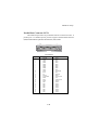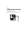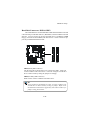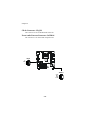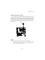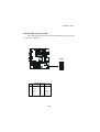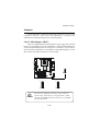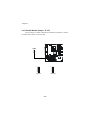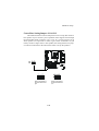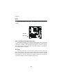
1
MSI
MICRO-STAR INTERNATIONAL
MD-3000 Micro ATX Mainboard
Version 1.0
i
Manual Rev: 1.0
Release Date: Dec. 2001
FCC-B Radio Frequency Interference Statement
This equipment has been tested and found to comply with the limits for a class
B digital device, pursuant to part 15 of the FCC rules. These limits are designed
to provide reasonable protection against harmful interference when the equipment is operated in a commercial environment. This equipment generates, uses
and can radiate radio frequency energy and, if not installed and used in accordance with the instruction manual, may cause harmful interference to radio
communications. Operation of this equipment in a residential area is likely to
cause harmful interference, in which case the user will be required to correct
the interference at his own expense.
Notice 1
The changes or modifications not expressly approved by the party responsible for compliance could void the user’s authority to operate the equipment.
Notice 2
Shielded interface cables and A.C. power cord, if any, must be used in order to
comply with the emission limits.
VOIR LA NOTICE D’INSTALLATION AVANT DE RACCORDER AU
RESEAU.
Micro-Star International MD-3000
Tested to comply
with FCC Standard
For Home or Office Use
ii
Edition
Dec. 2001
Copyright Notice
The material in this document is the intellectual property of MICRO-STAR
INTERNATIONAL. We take every care in the preparation of this document,
but no guarantee is given as to the correctness of its contents. Our products
are under continual improvement and we reserve the right to make changes
without notice.
Trademarks
All trademarks are the properties of their respective owners.
AMD, Athlon and Duron are registered trademarks of AMD Corporation.
PS/2 and OS®/2 are registered trademarks of International Business Machines
Corporation.
Windows® 95/98/2000/NT/ME/XP are registered trademarks of Microsoft
Corporation.
Netware® is a registered trademark of Novell, Inc.
Award® is a registered trademark of Phoenix Technologies Ltd.
AMI® is a registered trademark of American Megatrends Inc.
Revision History
Revision
Revision History
iii
Date
Safety Instructions
1.
2.
3.
4.
5.
Always read the safety instructions carefully.
Keep this User’s Manual for future reference.
Keep this equipment away from humidity.
Lay this equipment on a reliable flat surface before setting it up.
The openings on the enclosure are for air convection hence protects the
equipment from overheating. DO NOT COVER THE OPENINGS.
6. Make sure the voltage of the power source and adjust properly 110/220V
before connecting the equipment to the power inlet.
7. Place the power cord such a way that people can not step on it. Do not
place anything over the power cord.
8. Always Unplug the Power Cord before inserting any add-on card or module.
9. All cautions and warnings on the equipment should be noted.
10. Never pour any liquid into the opening that could damage or cause electrical shock.
11. If any of the following situations arises, get the equipment checked by a
service personnel:
! The power cord or plug is damaged
! Liquid has penetrated into the equipment
! The equipment has been exposed to moisture
! The equipment has not work well or you can not get it work according
to User’s Manual.
! The equipment has dropped and damaged
! If the equipment has obvious sign of breakage
12. DO NOT LEAVE THIS EQUIPMENT IN AN ENVIRONMENT
UNCONDITIONED, STORAGE TEMPERATURE ABOVE 600 C (1400F), IT
MAY DAMAGE THE EQUIPMENT.
CAUTION: Danger of explosion if battery is incorrectly replaced.
Replace only with the same or equivalent type recommended by the
manufacturer.
iv
CONTENTS
Chapter 1. Getting Started ........................................................................ 1-1
Mainboard Specification ...................................................................... 1-2
Mainboard Layout ............................................................................... 1-4
Chapter 2. Hardware Setup ....................................................................... 2-1
Central Processing Unit: CPU .............................................................. 2-2
CPU Installation Procedures ......................................................... 2-2
CPU Core Speed Derivation Procedure ......................................... 2-3
Memory ................................................................................................ 2-4
Introduction to SDRAM ............................................................... 2-4
DIMM Module Combination ......................................................... 2-5
Installing DIMM Modules ............................................................ 2-5
Power Supply ....................................................................................... 2-6
ATX 20-Pin Power Connector ....................................................... 2-6
ATX 12V Power Connector: JPW1 ................................................ 2-6
Back Panel ............................................................................................ 2-7
Mouse Connector: JKBMS1 ......................................................... 2-7
Keyboard Connector: JKBMS1 ..................................................... 2-8
USB Connectors ............................................................................ 2-8
LAN (RJ-45) Jack ........................................................................... 2-9
Serial Port Connector: COM A & COM B1 .................................... 2-9
Joystick/Midi Connectors ........................................................... 2-10
Audio Port Connectors ............................................................... 2-10
SPDIF Connectors ....................................................................... 2-10
Parallel Port Connector: LPT1 ...................................................... 2-11
Connectors ......................................................................................... 2-12
Floppy Disk Drive Connector: FDD1 ........................................... 2-12
Hard Disk Connectors: IDE1 & IDE2 ........................................... 2-13
CD-In Connector: CD_IN1 .......................................................... 2-14
Front Audio Line-out Connector: JAUDIO1 ............................... 2-14
v
Fan Power Connectors: C_FAN1 ................................................. 2-15
Front Panel Connector: FP_1 ....................................................... 2-16
Front USB Connector: USB1 ....................................................... 2-17
SPDIF Bracket Jumper: JSPDIF1 .................................................. 2-18
Jumpers .............................................................................................. 2-19
Clear CMOS Jumper: JBAT1 ........................................................ 2-19
LAN Enable/Disable Jumper: JLAN1 ........................................... 2-20
Center/Bass Setting Jumper: J11 & J12 ........................................ 2-21
Slots ................................................................................................... 2-22
AGP (Accelerated Graphics Port) Slot ......................................... 2-22
PCI Slots ...................................................................................... 2-22
PCI Interrupt Request Routing .................................................... 2-23
Appendix A: Using SPDIF & 4-/6-channel Audio Function ..................... A-1
vi
Getting Started
Chapter 1. Getting Started
Getting Started
1
Congratulations on purchasing the MSI mainboard. MD-3000 Micro
ATX mainboard is an excellent computer mainboard based on the innovative Intel® Brookdale and ICH2 chipset, which supports the Intel®
Pentium 4 processor and provides you with a cost-effective solution.
TOPICS
Mainboard Specification
Mainboard Layout
MSI Special Features
1-1
1-2
1-5
1-6
Chapter 1
Mainboard Specification
CPU
Support Socket478 for Intel® Pentium 4(FC-PGA2) processor
Support 1.3GHz, 1.4GHz and up to 2.XGHz
Chipset
Intel® Brookdale chipset
- AGP 4x/2x universal slot
- Support 100MHz FSB
- Support 400MHz Intel NetBurst micro-architecture bus.
Intel® ICH2 chipset (360 BGA)
- AC’97 Controller integrated
- 2 full IDE channels, up to ATA100
- Integrated 10/100Mbit/sec Etherent
- Low pin count interface for Winbond SIO
Main Memory (This section refers only to S-DRAM Layout)
Support two 168-pin DIMM sockets
Support a 32 to 1GB memory using 512Mbit technology
Max. memory size: 2GB
Slots
One AGP (Accelerated Graphics Port) 2x/4x slot
Two PCI 2.2 32-bit Master PCI Bus slots, the third PCI can support 2
Master devices
Support 3.3v/5v PCI bus interface
On-boardIDE
An IDE controller on the ICH2 chipset provides IDE HDD/CD-ROM
with PIO, Bus Master and Ultra DMA 66/ 100 operation modes
Can connect to four IDE devices
1-2
Getting Started
On-board Peripherals
One floppy port that supports two FDD with 360KB, 720KB, 1.44MB
and 2.88MB
Two serial ports (COM A/ Reserved in pin header)
One parallel port that supports SPP/EPP/ECP modes
Four USB ports (2 rear connectors and 2 USB front pin header)
One RJ-45 connector
One Line-In/ 3 Line-Out/Game port
Network
Realtek 8100 single chip fast 10/100 Mb/s Ethernet controller
ACPI, APM supported
H/W Audio (option)
C-media CMI8738-6CH-MX
Support 6 channel audio
AC’97 2.1 compliant
Support SPDIF
BIOS
The mainboard BIOS provides “Plug & Play” BIOS that can detect
the periph-eral devices and expansion cards installed on the board
automatically
Support Desktop Management Interface (DMI) function that can record
your mainboard specifications
Dimension
Micro ATX Form Factor (24.4cm x 22.4cm)
Mounting
6 mounting holes
1-3
Chapter 1
Mainboard Layout
JPW1
Top: LAN Jack
Bottom: USB
ports
C_FAN1
FDD1
ATX
Power Supply
Top : mouse
Bottom: keyboard
Bottom:
Line-Out
Line-In CD_IN1
Mic
IDE 2
Intel
Brookdale
Chipset
Top :
Game port
IDE 1
COM B1
DIMM 1
Bottom:
COM A
SPDIF IN/OUT
DIMM 2
Top : Parallel Port
Winbond
W83627HF-AW
AGP Slot
JLAN1
C-media
CMI8738
JSPDIF1
BATT
+
RTL
8100L
PCI Slot 1
ICH2
FP_1
PCI Slot 2
USB1
FWH
JAUDIO1
PCI Slot 3
JBAT1
J11
J12
MD-3000 Micro ATX Mainboard
1-4
Hardware Setup
Chapter 2. Hardware Setup
Hardware Setup
2
This chapter provides you with the information about hardware setup
procedures. While doing the installation, be careful in holding the components and follow the installation procedures. For some components, if you
install in the wrong orientation, the components will not work properly.
Use a grounded wrist strap before handling computer components. Static
electricity may damage the components.
TOPICS
Central Processing Unit: CPU
Memory
Power Supply
Back Panel
Connectors
Jumpers
Slots
2-1
2-2
2-5
2-7
2-8
2-13
2-20
2-23
Chapter 2
Central Processing Unit: CPU
The mainboard supports Intel® Pentium® 4 processor in the 478 pin
package. The mainboard uses a CPU socket called PGA478 for easy CPU
installation. When you are installing the CPU, make sure the CPU has a heat
sink and a cooling fan attached on the top to prevent overheating. If you do not
find the heat sink and cooling fan, contact your dealer to purchase and install
them before turning on the computer.
Open Lever
CPU Installation Procedures
1. Pull the lever sideways away
Sliding
Plate
from the socket. Then, raise
the lever up to a 90-degree
angle.
2. Look for the dot/cut edge. The
Dot / Cut edge
dot/cut edge should point towards the lever pivot. The
CPU will only fit in the correct
orientation.
Close
Lever
3. Hold the CPU down firmly, and
then close the lever to complete the installation.
WARNING!
Overheating will seriously damage the CPU and system,
always make sure the cooling fan can work properly to
protect the CPU from overheating.
2-2
Hardware Setup
CPU Core Speed Derivation Procedure
If
CPU Clock
Core/Bus ratio
then CPU core speed
WARNING!
=
=
=
=
=
100MHz
14
Host Clock x Core/Bus ratio
100MHz x 14
1.4GHz
Overclocking
This motherboard is designed to support overclocking.
However, please make sure your components are able to
tolerate such abnormal setting, while doing overclocking.
Any attempt to operate beyond product specifications is
not recommended. We do not guarantee the damages or
risks caused by inadequate operation or beyond product
specifications.
2-3
Chapter 2
Memory (This section describes only S-DRAM
The mainboard provides 2 slots for 168-pin, 3.3V SDRAM DIMM with 4
memory banks. You can install PC133/PC100 SDRAM modules on the DIMM
slots (DIMM 1~2). Advice: DDR Modules have only one notch!
DIMM Slots
(DIMM 1~2)
Introduction to SDRAM
Synchronous DRAM (SDRAM) is a type of dynamic RAM memory
chip that has been widely used starting in the latter part of the 1990s. SDRAMs
are based on standard dynamic RAM chips, but have sophisticated features
that make them considerably faster. First, SDRAM chips are fast enough to be
synchronized with the CPU's clock, which eliminates wait states. Second, the
SDRAM chip is divided into two cell blocks, and data is interleaved between
the two so that while a bit in one block is being accessed, the bit in the other is
being prepared for access. This allows SDRAM to burst the second and
subsequent, contiguous characters at a rate of 10ns, compared to 60ns for the
first character.
SDRAM provides 800 MBps or 1 GBps data transfer depending on
whether the bus is 100MHz or 133MHz.
2-4
Hardware Setup
DIMM Module Combination
To operate properly, at least one DIMM module must be installed. Memory
modules can be installed on the slots in any order. You can install either singleor double-sided modules to meet your own needs.
Memory modules can be installed in any combination as follows:
Slot
Memory Module
Total Memory
DIMM 1
(Bank 0 & Bank 1)
DIMM 2
(Bank 2 & Bank 3)
S/D
32MB~1GB
S/D
32MB~1GB
Maximum System Memory Supported
S: Single Side
32MB~2GB
D: Double Side
Installing DIMM Modules
The DIMM slot has 2 Notch Keys “VOLT and DRAM”. The module will
only fit in the right orientation.
1. Insert the DIMM memory module vertically into the DIMM slot. Then push
it in.
DRAM
notch VOLT
notch
2. The plastic clip at each side of the DIMM slot will automatically close.
2-5
Chapter 2
Power Supply
The mainboard supports ATX power supply for the power system. Before inserting the power supply connector, always make sure that all components are installed properly to ensure that no damage will be caused.
ATX 20-Pin Power Connector
This connector allows you to connect to an ATX power supply. To
connect to the ATX power supply, make sure the plug of the power supply is
inserted in the proper orientation and the pins are aligned. Then push down
the power supply firmly into the connector.
ATX 12V Power Connector: JPW1
This 12V power connector is used to provide power to the CPU.
JPW1
4
3
2
1
10
20
1
11
ATX Power Supply Pin Definition
JPW1 Pin Definition
PIN
SIGNAL
1
2
3
4
GND
GND
12V
12V
PIN
SIGNAL
PIN
SIGNAL
1
2
3
4
5
6
7
8
9
3.3V
3.3V
GND
5V
GND
5V
GND
PW_OK
5V_SB
10
12V
11
12
13
14
15
16
17
18
19
20
3.3V
-12V
GND
PS_ON
GND
GND
GND
-5V
5V
5V
2-6
Hardware Setup
Back Panel
The Back Panel provides the following connectors:
Midi/Joystick
Parallel
LAN
Mouse
Keyboard USB
SPDIF SPDIF Line-in
IN
OUT
COM A
Center / Bass
(2 Channel output speaker)
Line-out (Rear)
(2 Channel output speaker)
Line-out (Front)
(2 Channel output speaker)
Mouse Connector: JKBMS1
The mainboard provides a standard PS/2® mouse mini DIN connector for
attaching a PS/2 ® mouse. You can plug a PS/2® mouse directly into this
connector. The connector location and pin assignments are as follows:
Pin Definition
6
5
3
4
2
1
PS/2 Mouse (6-pin Female)
PIN
SIGNAL
DESCRIPTION
1
2
3
4
5
6
Mouse DATA
NC
GND
VCC
Mouse Clock
NC
Mouse DATA
No connection
Ground
+5V
Mouse clock
No connection
2-7
Chapter 2
Keyboard Connector: JKBMS1
The mainboard provides a standard PS/2® keyboard mini DIN connector
for attaching a PS/2® keyboard. You can plug a PS/2® keyboard directly into
this connector.
Pin Definition
6
5
3
4
1
2
PS/2 Keyboard (6-pin Female)
PIN
SIGNAL
DESCRIPTION
1
2
3
4
5
6
Keyboard DATA
NC
GND
VCC
Keyboard Clock
NC
Keyboard DATA
No connection
Ground
+5V
Keyboard clock
No connection
USB Connectors
The mainboard provides a UHCI (Universal Host Controller Interface)
Universal Serial Bus root for attaching USB devices such as keyboard, mouse
or other USB-compatible devices. You can plug the USB device directly into
the connector.
USB Port Description
1
2
3
4
5
6
7
8
USB Ports
PIN
SIGNAL
DESCRIPTION
1
2
3
4
5
6
7
8
VCC
-Data 0
+Data0
GND
VCC
-Data 1
+Data 1
GND
+5V
Negative Data Channel 0
Positive Data Channel 0
Ground
+5V
Negative Data Channel 1
Positive Data Channel 1
Ground
2-8
Hardware Setup
LAN (RJ-45) Jack
The mainboard provides one standard RJ-45 jack for connection to Local
Area Network (LAN). You can connect a network cable to the LAN jack.
Pin Definition
PIN
SIGNAL
DESCRIPTION
1
TDP
Transmit Differential Pair
2
TDN
Transmit Differential Pair
3
RDP
Receive Differential Pair
4
NC
Not Used
5
NC
Not Used
6
RDN
Receive Differential Pair
7
NC
Not Used
8
NC
Not Used
Serial Port Connector: COM A & COM B1
The mainboard offers two 9-pin male DIN connectors for serial port COM
A and COM B1. The ports are 16550A high speed communication ports that
send/receive 16 bytes FIFOs. You can attach a serial mouse or other serial
devices directly to them.
COM A
Pin Definition
1 2 3 4
6 7 8 9
9-Pin Male DIN Connectors
COM B1
1 2 3 4 5
PIN
SIGNAL
DESCRIPTION
1
2
3
4
5
6
7
8
9
DCD
SIN
SOUT
DTR
GND
DSR
RTS
CTS
RI
Data Carry Detect
Serial In or Receive Data
Serial Out or Transmit Data
Data Terminal Ready)
Ground
Data Set Ready
Request To Send
Clear To Send
Ring Indicate
6 7 8 9
2-9
Chapter 2
Joystick/Midi Connectors
You can connect a joystick or game pad to this connector.
Audio Port Connectors
Line In is used for external CD
player, Tape player, or other audio
devices. Line Out are connectors for
Speakers or Headphones. Center/Bass
is a connector for audio device which is
used as a center speaker or supports
bass effect.
Line-in
Center / Bass
(2 Channel output speaker)
Note: Details on the application of 6-channel audio can be
acquired in Appendix A.
Line-out (Rear)
(2 Channel output speaker)
Line-out (Front)
(2 Channel output speaker)
SPDIF Connectors
The SPDIF connectors privided on the back pannel can be used to connect your digital audio equipment.
SPDIF
IN
SPDIF
OUT
Note: Details on the application of 6-channel audio can be acquired
in Appendix A.
2-10
Hardware Setup
Parallel Port Connector: LPT1
The mainboard provides a 25-pin female centronic connector for LPT. A
parallel port is a standard printer port that supports Enhanced Parallel Port
(EPP) and Extended Capabilities Parallel Port (ECP) mode.
13
1
14
25
Pin Definition
PIN
SIGNAL
DESCRIPTION
1
2
3
4
5
6
7
8
9
10
11
12
13
14
15
16
17
18
19
20
21
22
23
24
25
STROBE
DATA0
DATA1
DATA2
DATA3
DATA4
DATA5
DATA6
DATA7
ACK#
BUSY
PE
SELECT
AUTO FEED#
ERR#
INIT#
SLIN#
GND
GND
GND
GND
GND
GND
GND
GND
Strobe
Data0
Data1
Data2
Data3
Data4
Data5
Data6
Data7
Acknowledge
Busy
Paper End
Select
Automatic Feed
Error
Initialize Printer
Select In
Ground
Ground
Ground
Ground
Ground
Ground
Ground
Ground
2-11
Chapter 2
Connectors
The mainboard provides connectors to connect to FDD, IDE HDD, case,
LAN, USB Ports, and CPU/System FAN.
Floppy Disk Drive Connector: FDD1
The mainboard provides a standard floppy disk drive connector that
supports 360K, 720K, 1.2M, 1.44M and 2.88M floppy disk types.
FDD1
2-12
Hardware Setup
Hard Disk Connectors: IDE1 & IDE2
The mainboard has a 32-bit Enhanced PCI IDE and Ultra DMA 33/66/100
controller that provides PIO mode 0~4, Bus Master, and Ultra DMA/33/66/100
function. You can connect up to four hard disk drives, CD-ROM, 120MB
Floppy (reserved for future BIOS) and other devices. These connectors support the provided IDE hard disk cable.
IDE2
IDE1
IDE1 (Primary IDE Connector)
The first hard drive should always be connected to IDE1. IDE1 can
connect a Master and a Slave drive. You must configure second hard
drive to Slave mode by setting the jumper accordingly.
IDE2 (Secondary IDE Connector)
IDE2 can also connect a Master and a Slave drive.
TIP:
If you install two hard disks on cable, you must configure the
second drive to Slave mode by setting its jumper. Refer to the
hard disk documentation supplied by hard disk vendors for
jumper setting instructions.
2-13
Chapter 2
CD-In Connector: CD_IN1
The connector is for CD-ROM audio connector.
Front Audio Line-out Connector: JAUDIO1
The connector is for front audio output devices.
CD_IN1
R
GND
L
JAUDIO1
AUXL
MIC
GND
AUXR
2-14
Hardware Setup
Fan Power Connectors: C_FAN1
The C_FAN1 (processor fan) supports system cooling fan with +12V. It
supports three-pin head connector. When connecting the wire to the
connectors, always take note that the red wire is the positive and should be
connected to the +12V, the black wire is Ground and should be connected to
GND. If the mainboard has a System Hardware Monitor chipset on-board, you
must use a specially designed fan with speed sensor to take advantage of the
CPU fan control.
SENSOR
+12V
GND
C_FAN1
Note:
1. Always consult the vendor for proper CPU cooling fan.
2. CPU Fan supports the fan control. You can install the PC Alert
utility that will automatically control the CPU Fan speed according to the actual CPU temeperature.
2-15
Chapter 2
Front Panel Connectors: FP_1
The case connector block FP_1 allows you to connect to the Power
Switch, Reser Switch, Speaker, Power LED, and HDD LED on the case.
FP_1
Power Switch
Power LED
HDD LED
Reset Switch
2-16
Hardware Setup
Front USB Connector: USB1
The mainboard provides a front Universal Serial Bus connector for users
to connect to USB port.
USB1
USB1 Pin Definition
Pin
Description
Pin
Description
1
USBPWR
2
GND
3
USBDT2-
4
GND
5
USBDT2+
6
USBDT3+
7
GND
8
USBDT3-
9
GND
10
USBPWR
2-17
10
9
2
1
Chapter 2
SPDIF Bracket Jumper: JSPDIF1
The mainboard comes with a jumper for users to connect an optional
bracket for SPDIF output and input.
JSPDIF1
7
1
8
2
JSPDIF1 Pin Definition
Pin
Description
Pin
Description
1
+12V
2
NC
3
NC
4
SPDIFO
5
SPDIFI
6
GND
7
SPDIF2
8
SPGPIO
2-18
Hardware Setup
Jumpers
The motherboard provides the following jumpers for you to set the
computer’s function. This section will explain how to change your
motherboard’s function through the use of these jumpers.
Clear CMOS Jumper: JBAT1
There is a CMOS RAM on board that has a power supply from external
battery to keep the data of system configuration. With the CMOS RAM, the
system can automatically boot OS every time it is turned on. If you want to
clear the system configuration, use the JBAT1 (Clear CMOS Jumper ) to clear
data. Follow the instructions below to clear the data:
1
JBAT1
WARNING!
3
3
1
1
Keep Data
Clear Data
You can clear CMOS by shorting 2-3 pin while the
system is off. Then return to 1-2 pin position. Avoid
clearing the CMOS while the system is on; it will damage the mainboard.
2-19
Chapter 2
LAN Enable/Disable Jumper: JLAN1
Use the jumper to enable or disable the onboard LAN function. Follow
the instructions below to clear the data:
JLAN1
1
3
3
1
1
LAN Enable
LAN Disable
2-20
Hardware Setup
Center/Bass Setting Jumper: J11 & J12
The mainboard comes with two Jumpers for users to set up their center or
bass speaker. If you connect a pair of speakers which supports bass through
the Center/Bass audio connector (refer to P.2-11), you may need to set up
which speaker can output bass in order to get a better sound effect. If you
merely connect a single center or bass speaker, the setting of these two jumpers will be invalid. Follow the instructions below to set up the speakers:
1
3
1
3
J11
J12
1
3
1
3
Set the center speaker to
the left and woofer to the
right
1
3
1
3
Set the center speaker to
the right and woofer to the
left
2-21
Chapter 2
Slots
The motherboard provides three 32-bit Master PCI bus slots and one
AGPslot.
AGP Slot
PCI Slots
AGP (Accelerated Graphics Port) Slot
The AGP slot allows you to insert the AGP graphics card. AGP is an
interface specification designed for the throughput demands of 3D graphics.
It introduces a 66MHz, 32-bit channel for the graphics controller to directly
access main memory and provides three levels of throughputs: 1x (266Mbps),
2x (533Mbps) and 4x (1.07Gbps).
PCI Slots
Three PCI slots allow you to insert the expansion cards to meet your
needs. When adding or removing expansion cards, make sure that you unplug
the power supply first. Meanwhile, read the documentation for the expansion
card to make any necessary hardware or software settings for the expansion
card, such as jumpers, switches or BIOS configuration.
2-22
Hardware Setup
PCI Interrupt Request Routing
The IRQ, abbreviation of interrupt request line and pronounced I-R-Q,
are hardware lines over which devices can send interrupt signals to the
microprocessor. The PCI IRQ pins are typically connected to the PCI bus INT
A# ~ INT D# pins as follows:
Order 1
Order 2
Order 3
Order 4
PCI Slot 1
INT A#
INT B#
INT C#
INT D#
PCI Slot 2
INT B#
INT C#
INT D#
INT A#
PCI Slot 3
INT C#
INT D#
INT A#
INT B#
2-23
Using SPDIF & 4-/6-channel Audio Function
Appendix A: Using 4-/6-channel Audio
Function
Using SPDIF & 4-/6-channel Audio
A
Function
The mainboard comes with C-Media 6-channel audio function, which
allows you to attach digital audio device or 4/6 speakers for better space sound
effect. The section will tell you how to activate SPDIF or 4-/6-channel audio
function.
TOPICS
Installing C-Media Drivers
Hardware Configuration
Software Configuration
A-1
A-2
A-2
A-3
Appendix A
Installing C-Media Drivers
The mainboard is able to active the audio connectors from 2-channel to 4-/6channel or the SPDIF connectors. To use the function, you need to install the
C-Media drivers.
To install C-Media drivers:
1. Insert the companion CD into the CD-ROM drive. The setup screen will
automatically appear.
2. Click on C-Media Sound Drivers.
3. Follow the on-screen instructions to complete installation.
4. Restart the system.
Note: For Windows NT4.0, you need to install the C-Media Sound
Drivers manually.
Hardware Configuration
After installing the C-Media drivers, you can attach the speakers for 4-/6channel audio output. Always connect the speakers to the LINE OUT
connectors. The SPDIF is void when 4-/6-channel audio output is active. Different connector configurations for 2-/4-/6-channel operations are listed below:
2-Channel
SPDIF
IN
SPDIF
OUT
LINE
IN
LINE
LINE
LINE
OUT
OUT
OUT
(Front) (Rear) (C/Bass)
4-Channel
SPDIF
IN
SPDIF
OUT
LINE
IN
LINE
LINE
LINE
OUT
OUT
OUT
(Front) (Rear) (C/Bass)
6-Channel
SPDIF
IN
SPDIF
OUT
LINE
IN
LINE
LINE
LINE
OUT
OUT
OUT
(Front) (Rear) (C/Bass)
A-2
In 2-channel configuration, Line
In, Line Out (Front) and SPDIF
connectors are active.
When set to 4-channel
configuration,Line In, Line Out
(Front) and Line Out (Rear)
connectors are active.
When set to 6-channel
configuration, Line In, Line Out
(Front), Line Out (Rear), Line
Out (C/Bass) connectors are
active.
Using SPDIF & 4-/6-channel Audio Function
Software Configuration
To have 4-/6-channel audio work, you must set appropriate configuration in
the C-Media software application.
To set the multi-channel configuration:
1. Click the C-Media Mixer icon
from the window tray on the bottom.
2. The following screen appears. Click the indicated button.
Click here
3. The “Advanced” window appears.
4. Select 5.1 for 6-channel or 4 for 4-channel audio output.
5. Click OK.
A-3