1
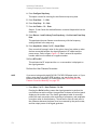
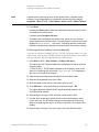
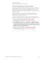
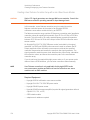
GPS Modulation (Option 409)
Real Time GPS
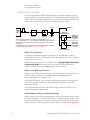
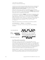
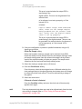
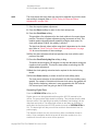
The maximum data rate for this input connector is 50 Mb/s with a voltage
range of
−0.5 to 5.5 V.
The chip rate of the external source must match the chip rate value set using
the GPS Ref (f0) softkey.
NOTE
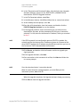
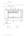
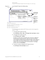
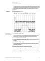
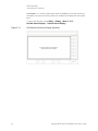
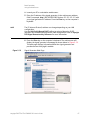
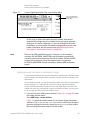
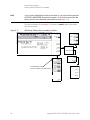
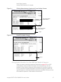
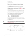
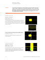
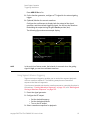
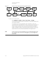
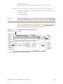
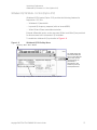
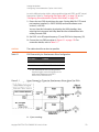
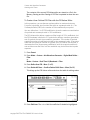
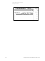
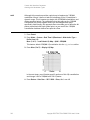
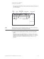
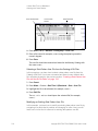
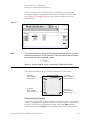
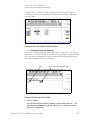
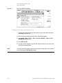
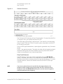
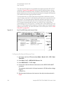
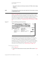
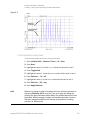
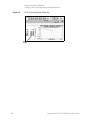
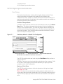
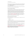
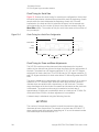
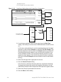
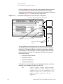
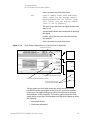
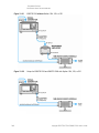
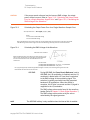
Figure 8-7 on page 249 shows what the signal generator display should look
like after all the steps have been completed. The CA Chip Rate, P Chip
Rate, GPS Ref (f0), and GPS Ref Clk fields in the status area of the display
show the new parameters you set in this procedure. Notice the settings
Satellite ID, Doppler Shift, Data, and Data Mode, have not changed
from the previous procedure, “Setting Up the Real Time GPS Signal” on page
247.
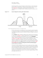
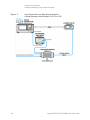
Figure 8-7
Real Time GPS Setup with External Clock
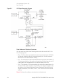
This procedure used an external source as the reference clock signal. The
reference frequency was changed from the GPS standard of 10.23 Mcps to
11.03 kcps. This change in the reference signal frequency automatically
changed the P and C/A code chip rates. Since the P code chip rate matches
the reference frequency, its chip rate is now 11.03 kcps; the C/A code rate is
one-tenth of the reference frequency and so is now 1.103 kcps. For more
information on the GPS option, refer to “Real Time GPS” on page 243.
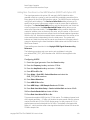
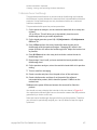
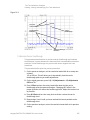
Testing Receiver Sensitivity
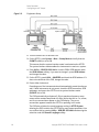
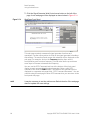
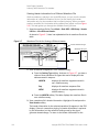
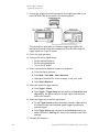
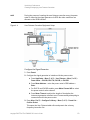
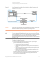
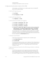
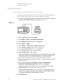
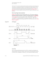
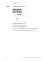
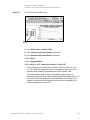
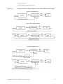
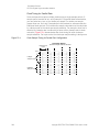
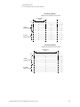
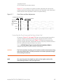
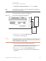
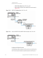
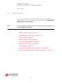
Refer to Figure 8-8.
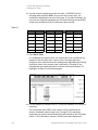
1. Connect the cables between the receiver and the PSG as shown in Figure
8-8.
Keysight E8357D/67D & E8663D PSG User’s Guide
249