1
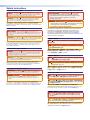
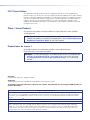
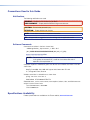
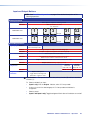
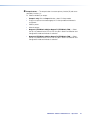
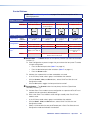
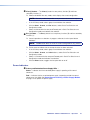
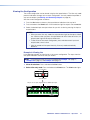
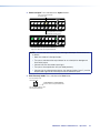
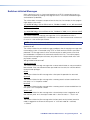
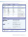
Command and Response Table for SIS Commands (continued)
Command Function
SIS Command
Response
(Host to Unit)
(Unit to Host)
Additional description
View ties, mutes, and presets (continued)
View all output mute status
EVM}
Each X# response is the mute status of an
output, starting from output 1. n is the highestnumbered output.
X#1X#2X#3 ... X#n
NOTES:
• The switcher reports the mute status for all outputs, up to the highest numbered output on the highest numbered slot with an
I/O board installed. The switcher does not recognize gaps in the board installation. For example, if boards are installed in only
slots 1 and 3, leaving slot 2 empty, the switcher returns mute status for 24 sequential outputs. The mute status for the outputs in
slot 2, inputs 9 through 16, can be ones or zeroes (the switcher allows you to mute an output that is not installed, so long as it is
numbered lower than the highest numbered output installed).
• When the switcher is in Verbose mode 1 or 3 (see the Set verbose mode SIS command on page 69), the response includes
“Mut” before the X#s.
View global preset
configuration
Command description:
Response description:
Example (8 x 8 matrix):
EX&*X@*1VC}
X!n•X!n+1•...•X!n+15•Vid]
Show the configuration of preset X&. Show the
input tied to 16 sequential outputs, starting
from output X@.
preset # (X&)*starting output # (X@)*1VC}
input # (X!) tied to X@n•X! tied to X@n+1•X! tied to X@n+2• ... •X! tied to X@n+15•Vid]
E23*1*1VC}
input 8 tied to output 4
input 2 tied to output 3
no tied input
outputs do not exist
•--•--•--•--•--•--•--•--•
Response = tied input: 08•08•02•08•08•01•00•00•
•Vid
Output: 1
2
3 4
5 6
7
8 09 10 11 12 13 14 15 16
Each position shown in the response is an output: left = starting output number (1 in this example),
right = starting output number + 15 (16 in this example). (Outputs 9 through 16 are not present on this matrix
switcher.) The number in each position is the input tied to that output.
In this example, for preset 23, video input 8 is tied to outputs 1, 2, 4, and 5; input 2 is tied to output 3; and
input 1 is tied to output 6. No inputs are tied to outputs 7 and 8.
NOTE: EX&*1*X@VC} where X& = 0 returns 16 ties in the current video configuration of the switcher, starting from output X@.
View room preset
configuration
Command description:
Response description:
EX**X1)*X@*1VC}
X!n•X!n+1•...•X!n+15•Vid]
Show configuration of room X*, preset X1).
Show the input tied to up to 16 outputs
assigned to room X*.
room # (X*)*room preset # (X1))*starting output # (X@)*1VC
input # (X!) tied to X@•X! tied to X@+1•X! tied to X@+2• ... •X! tied to X@+15•Vid]
List input link detection
NOTE: The switcher reports the link status for all outputs, up to the highest numbered output on the highest numbered slot with an I/O
board installed. The switcher does not recognize gaps in the board installation. For example, if only two boards are installed, in slots 1
and 3, leaving slot 2 empty, the switcher returns link status for 24 sequential inputs. The input link response for the inputs supported by
the board in slot 2, inputs 9 through 16, are all zeroes.
View all input connections
Example (32 x 32 matrix):
0LS
LS
X1!1X1!2X1!3X1!4...X1!n]
no input detected
Each X1! response is the connection status of
an input, starting from input 1.
n is the highest-numbered input.
input detected
Response Status: 0 0 0 1 1 1 0. . .0
Input: 1 2 3 4 5 6 7 32
NOTE: X! = Input number (for tie)
X@ = Output number
X# = Mute
X& = Global preset number
X* = Room number (for room presets)
X1) = Room preset number
X1! = Connection status
00 – (maximum number of inputs for your configuration) (00 = untied)
01 – (maximum number of outputs for your configuration)
0 = not muted, 1 = muted
00 – 32 (FOX Matrix 3200) or 64 (FOX Matrix 7200) (00 = current configuration for view only)
01 – 10 maximum (each can have up to 10 presets (X1)) assigned)
01 – 10 maximum
0 = no input connected
1 = input connected
FOX Matrix 3200 and 7200 Switchers • Programming Guide
62