1
103
4.2 Communications
The communication will design will be differ from each system. The system that
will be taken into account will be the hand held unit system and the control box
unit. The software should be able to handle the different devices should as the
display, the air flow sensor, the alcohol sensor, the LEDs, and other devices
used by each of the systems. The communication software should have certain
routines that will invoke different function to handle the certain task to
communicate with the devices. These routines should be able to have interrupt
handler just in case an error is sent. The basic skeleton should involve a
message pump procedure that will be able to distinguish from what message.
The message pump routine will allow certain classes to post the message on
itself to save in the message state. Each message will invoke a different routine
depending on the message that was received by the message pump. This
message pump will act a manger that will distribute the necessary parameters
that will each message to be utilized in an effect way. These parameters can be
the BAC value, air flow pressure, and other components received by inputs.
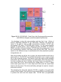
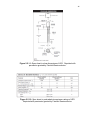
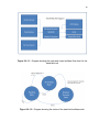
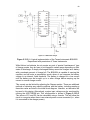
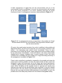
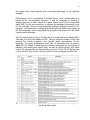
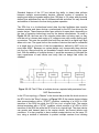
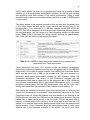
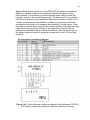
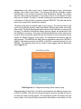
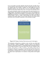
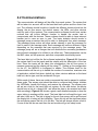
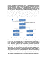
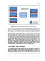
The hand held unit will be the first software implantation. Figure 4.2-1 illustrates
the system itself from the inputs and the outputs with the description of the bus
lines. Since the inputs will be taken into consideration, the air flow sensor to
measure pressure and the display will be using I2C. Setting up the configuration
for the I2C, the MSP430 is configured to enable. The software itself for the
communication will be set up to handle the number of connection, maximum size
of application, default link token, default join token, devices address on the hand
held unit, device type, and the end device Rx type.
Within each of these, there are certain commands that can be passed to achieve
these goals. The access point should be able to configure three things, initialize
the HW/Radio, handle the linking, and receive the message. The access point
will act as a hub for the hand held unit system. On the end device, the device
should have a link id, a board HW, and allow the data to be received and dealt
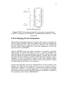
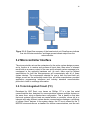
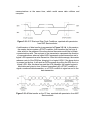
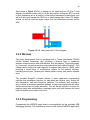
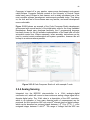
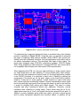
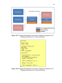
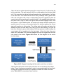
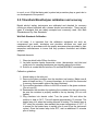
with accordingly. Figure 4.2-2 shows a great a well detailed example on how the
senor taking in readings will be used. The hand held unit will read the input, and
will take it with an id. The link id string for the air flow sensor will be airFlow and
the display link id string will be lcdDisplay. These link ids will be significant when
the end device passes the link id to the hub. The hub will always require a link id.
If none of the link ids are used then the end module will go into sleep mode.