1
®
Topo USA 4.0
User Guide
Table of Contents
Table Of Contents
TABLE OF CONTENTS ............................................................................................................................................................ 1
WELCOME .................................................................................................................................................................................... 8
W ELCOME TO TOPO USA 4.0 .....................................................................................................................................................8
RUNNING TOPO USA 4.0 ............................................................................................................................................................8
To Run Topo USA 4.0............................................................................................................................................................ 9
EXITING TOPO USA 4.0...............................................................................................................................................................9
TOPO USA 4.0 CD DATA REGIONS...........................................................................................................................................9
TOPO USA 4.0 FILE DIRECTORIES...........................................................................................................................................10
SAVING TOPO USA DATA TO YOUR HARD DISK DRIVE .....................................................................................................11
To Save Topo USA Data.....................................................................................................................................................11
FREQUENTLY A SKED QUESTIONS............................................................................................................................................11
How do I create a route on the map?...............................................................................................................................11
How do I save a route?.......................................................................................................................................................11
How do I find a specific location?....................................................................................................................................11
How do I transfer waypoints?............................................................................................................................................12
How do I bring in maps from another DeLorme program? .........................................................................................12
How do I bring in draw files created in another DeLorme program? .......................................................................12
How do I fix the roads on my map?..................................................................................................................................12
Can I design my own symbols to use with Topo USA 4.0?...........................................................................................12
How do I initialize my GPS receiver? ..............................................................................................................................12
How can I get information about an item on the map?.................................................................................................12
What is a project?................................................................................................................................................................13
What do the different colors and symbols on the map mean?......................................................................................13
How do I zoom in for a closer view of the map?............................................................................................................13
How do I find all landmarks within ten miles of a specific location on the map?....................................................13
HELP ..............................................................................................................................................................................................14
HELP OVERVIEW ........................................................................................................................................................................14
On-Screen Help....................................................................................................................................................................14
Help Menu.............................................................................................................................................................................14
CONTEXT -SENSITIVE HELP .......................................................................................................................................................14
U SING THE HELP SYSTEM .........................................................................................................................................................14
Contents.................................................................................................................................................................................14
HELP DOCUMENTATION CONVENTIONS .................................................................................................................................16
TOPO USA 4.0 U SER GUIDE .....................................................................................................................................................16
On-Screen Help....................................................................................................................................................................16
ToolTips.................................................................................................................................................................................17
Information Boxes................................................................................................................................................................17
BASIC FUNCTIONS .................................................................................................................................................................18
BASIC FUNCTIONS OVERVIEW .................................................................................................................................................18
To Control the Map .............................................................................................................................................................18
To Use the Tabs....................................................................................................................................................................18
DRAG AND ZOOM.......................................................................................................................................................................18
To Zoom In ............................................................................................................................................................................18
To Zoom Out.........................................................................................................................................................................18
PANNING/CENTERING THE M AP...............................................................................................................................................19
CONTROL PANEL........................................................................................................................................................................20
M AP ROTATION TOOL ...............................................................................................................................................................20
To Change the Map Rotation.............................................................................................................................................21
M EASURING DISTANCE AND A REA .........................................................................................................................................21
To Measure Distance or Area............................................................................................................................................21
U SING THE OVERVIEW M AP .....................................................................................................................................................22
1
Table of Contents
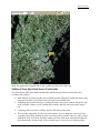
U SING THE SECONDARY M AP...................................................................................................................................................22
Accessing Data Collections................................................................................................................................................22
Additional Facts About Split-Screen Functionality.......................................................................................................23
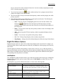
RIGHT -CLICK M OUSE OPTIONS ...............................................................................................................................................24
Add MapNote........................................................................................................................................................................24
Convert to Waypoint/Via ....................................................................................................................................................25
Copy to Draw Object...........................................................................................................................................................25
Delete Options......................................................................................................................................................................25
Edit Draw Object .................................................................................................................................................................25
Info..........................................................................................................................................................................................26
Profile/Add to Profile..........................................................................................................................................................26
Route: Create Route Options.............................................................................................................................................26
Route: Activate, Hide, Delete, and Profile Route Options...........................................................................................27
Right-Click Options in the Find Results List...................................................................................................................27
GETTING INFORMATION A BOUT M AP FEATURES..................................................................................................................27
To Get Information About a Map Feature.......................................................................................................................27
To Copy Map Feature Information into Another Program..........................................................................................27
M OVING OR DELETING M AP TAGS, M AP NOTES, AND TEXT LABELS.................................................................................28
To Move Right-Click MapNotes........................................................................................................................................29
RESIZING THE M AP AND TAB A REAS......................................................................................................................................29
To Resize the Map and Tab Area Using the Resize Buttons.........................................................................................29
To Resize the Map and Tab Area Using the Drag Method...........................................................................................30
To Resize the Map and Tab Area Using Function Keys ...............................................................................................30
ZOOM LEVEL...............................................................................................................................................................................30
To Change Zoom Level Using the Zoom Level Tool......................................................................................................30
ZOOMING IN AND OUT...............................................................................................................................................................31
To Zoom In/Out Using the Zoom Tools ...........................................................................................................................31
FIND ...............................................................................................................................................................................................32
FIND OVERVIEW.........................................................................................................................................................................32
U SING QUICKSEARCH ...............................................................................................................................................................32
To Search for a Place, Address, ZIP Code, or Coordinate..........................................................................................32
M AP TAGS: M OVING, HIDING, AND DELETING ......................................................................................................................33
To Move a MapTag .............................................................................................................................................................33
To Hide MapTags................................................................................................................................................................33
To Delete MapTags .............................................................................................................................................................33
U SING A DVANCED SEARCH......................................................................................................................................................34
To Use Advanced Search....................................................................................................................................................34
KEYWORDS FOR CATEGORY SEARCHES .................................................................................................................................36
Notes on Category Searches..............................................................................................................................................38
TIPS ON VIEWING FIND RESULTS.............................................................................................................................................39
PRINT ............................................................................................................................................................................................41
PRINTING OVERVIEW.................................................................................................................................................................41
PRINTING A M AP ........................................................................................................................................................................41
To Print a Map.....................................................................................................................................................................41
A DDING A TITLE TO YOUR M AP ..............................................................................................................................................42
To Add a Map Title..............................................................................................................................................................42
SAVING A M AP AS A BITMAP IMAGE .......................................................................................................................................43
To Save a Map as a Bitmap................................................................................................................................................43
M ANUALLY A SSEMBLING A M ULTIPAGE M AP......................................................................................................................44
To Manually Assemble a Multipage Map........................................................................................................................44
PRINTING A ROUTE AND DIRECTIONS.....................................................................................................................................47
To Print a Route...................................................................................................................................................................48
SAVING ROUTE DIRECTIONS AS TEXT ....................................................................................................................................48
To Save Your Route Directions.........................................................................................................................................49
PRINTING A PROFILE ..................................................................................................................................................................49
To Print a Profile.................................................................................................................................................................49
2
Table of Contents
PRINTING TIPS............................................................................................................................................................................50
For Laser Printers ...............................................................................................................................................................50
For Black-and-White Printers...........................................................................................................................................50
MAPDATA....................................................................................................................................................................................51
M AP DATA OVERVIEW...............................................................................................................................................................51
What Is a Project? ...............................................................................................................................................................51
How Do I View Multiple Datasets With One CD-ROM Drive? ..................................................................................51
What is Exchange?..............................................................................................................................................................51
Can I Reuse Draw Files and Routes in Other Projects? ..............................................................................................51
How Do I Manage My Map Data?...................................................................................................................................52
Can I Send Routes or Draw Files to Another Topo USA 4.0 User? ...........................................................................52
CREATING AND DELETING PROJECTS......................................................................................................................................52
To Create a New Project ....................................................................................................................................................52
To Delete a Project..............................................................................................................................................................52
OPENING A PROJECT ..................................................................................................................................................................52
To Open a Project................................................................................................................................................................52
A DDING/REMOVING FILES IN A PROJECT ...............................................................................................................................53
To Add/Remove Files Contained in a Project.................................................................................................................53
RENAMING A PROJECT ...............................................................................................................................................................54
To Rename a Project ...........................................................................................................................................................54
TRANSFERRING FILES................................................................................................................................................................54
To Create a Transfer File...................................................................................................................................................54
To E-mail a Transfer File...................................................................................................................................................55
To Import a Transfer File...................................................................................................................................................55
TRANSFERRING M AP DATA LOCATIONS.................................................................................................................................55
To Transfer Map Data Locations......................................................................................................................................55
DRAW ............................................................................................................................................................................................56
DRAW OVERVIEW ......................................................................................................................................................................56
What is a Draw File?..........................................................................................................................................................56
What Are Draw Objects?....................................................................................................................................................56
What are Line Objects? ......................................................................................................................................................56
What are Area Objects?......................................................................................................................................................57
What are Point Objects?.....................................................................................................................................................57
HIDDEN DRAW TOOLS...............................................................................................................................................................57
To View the Hidden Draw Tools.......................................................................................................................................57
EXPORTING DRAW FILES TO TEXT FILES ...............................................................................................................................57
To Export Draw Files to Text Files ..................................................................................................................................57
IMPORTING FILES TO DRAW FILES...........................................................................................................................................58
To Import Files.....................................................................................................................................................................58
DRAW FILES ..............................................................................................................................................................................60
DRAW FILES OVERVIEW ...........................................................................................................................................................60
CREATING A NEW DRAW FILE .................................................................................................................................................60
To Create a New Draw File...............................................................................................................................................61
SAVING A DRAW FILE................................................................................................................................................................61
To Save a New Draw File...................................................................................................................................................61
DELETING A DRAW FILE ...........................................................................................................................................................61
To Delete a Draw File ........................................................................................................................................................62
M ANAGING M ULTIPLE DRAW FILES .......................................................................................................................................62
To Manage Multiple Draw Files.......................................................................................................................................62
HIDING DRAW FILES..................................................................................................................................................................62
To Hide a Draw File ...........................................................................................................................................................62
DRAW OBJECTS .......................................................................................................................................................................64
DRAW OBJECTS OVERVIEW......................................................................................................................................................64
Points in Routable Roads/Trails, Tracks, Lines, Splines, Polygons, and Highlights...............................................64
3
Table of Contents
Points in Rectangles, Circles, and Arcs...........................................................................................................................64
Points in Point Draw Objects ............................................................................................................................................65
Points in MapNotes.............................................................................................................................................................65
COPYING AND PLACING DRAW OBJECTS................................................................................................................................65
To Copy Draw Objects........................................................................................................................................................65
COPYING A M AP LINE TO THE DRAW FILE.............................................................................................................................66
To Copy a Map Line............................................................................................................................................................66
M OVING DRAW OBJECTS..........................................................................................................................................................66
To Move Draw Objects .......................................................................................................................................................66
DELETING DRAW OBJECTS.......................................................................................................................................................67
To Delete One Draw Object...............................................................................................................................................67
To Delete Multiple Draw Objects .....................................................................................................................................68
To Delete All Draw Objects ...............................................................................................................................................68
SNAPPING DRAW OBJECTS.......................................................................................................................................................68
To Snap a Draw Object to the Coordinates of Another Object ...................................................................................68
To Snap the Central Shape Point of an Arc to Another Object ...................................................................................69
A DDING POINTS TO DRAW OBJECTS.......................................................................................................................................69
To Add Points to Draw Objects.........................................................................................................................................69
DELETING POINTS AND LINE SEGMENTS FROM DRAW OBJECTS........................................................................................70
To Delete Points and Line Segments from Draw Objects.............................................................................................70
LINE OBJECTS ..........................................................................................................................................................................71
LINE OBJECTS OVERVIEW.........................................................................................................................................................71
ROUTABLE ROADS: DRAWING, EDITING, AND PLACING......................................................................................................71
To Draw Routable Roads...................................................................................................................................................71
To Edit a Routable Road Line...........................................................................................................................................72
To Place a Routable Road at a Specific Location..........................................................................................................73
ROUTABLE TRAILS: DRAWING, EDITING, AND PLACING .....................................................................................................74
To Draw Routable Trails....................................................................................................................................................74
To Edit a Routable Trail Line............................................................................................................................................75
To Place a Routable Trail at a Specific Location ..........................................................................................................76
EDITING A TRACK ......................................................................................................................................................................76
To Edit a Track.....................................................................................................................................................................76
LINES: DRAWING, EDITING, AND PLACING ............................................................................................................................77
To Draw a Line ....................................................................................................................................................................77
To Edit a Line.......................................................................................................................................................................78
To Place a Line at a Specific Location............................................................................................................................79
A RCS: DRAWING, EDITING, AND PLACING.............................................................................................................................80
To Draw an Arc....................................................................................................................................................................80
To Edit an Arc ......................................................................................................................................................................81
To Place an Arc at a Specific Location............................................................................................................................82
SPLINES: DRAWING, EDITING, AND PLACING ........................................................................................................................82
To Draw a Spline.................................................................................................................................................................82
To Edit a Spline....................................................................................................................................................................83
To Place a Spline at a Specific Location.........................................................................................................................84
HIGHLIGHTS: DRAWING, EDITING, AND PLACING.................................................................................................................85
To Draw a Highlight ...........................................................................................................................................................85
To Edit a Highlight..............................................................................................................................................................85
To Place a Highlight at a Specific Location ...................................................................................................................86
JOINING AND BREAKING LINEAR OBJECTS............................................................................................................................87
To Join ...................................................................................................................................................................................87
To Break ................................................................................................................................................................................87
AREA OBJECTS ........................................................................................................................................................................88
A REA OBJECTS OVERVIEW.......................................................................................................................................................88
CIRCLES: DRAWING, EDITING, AND PLACING........................................................................................................................88
To Draw a Circle .................................................................................................................................................................88
To Edit a Circle....................................................................................................................................................................89
4
Table of Contents
To Place a Circle at a Specific Location.........................................................................................................................89
RECTANGLES: DRAWING, EDITING, AND PLACING...............................................................................................................89
To Draw a Rectangle...........................................................................................................................................................90
To Edit a Rectangle.............................................................................................................................................................90
To Place a Rectangle at a Specific Location..................................................................................................................90
POLYGONS: D RAWING, EDITING, AND PLACING ...................................................................................................................91
To Draw a Polygon .............................................................................................................................................................91
To Edit a Polygon ................................................................................................................................................................92
To Place a Polygon at a Specific Location.....................................................................................................................92
POINT OBJECTS .......................................................................................................................................................................94
POINT OBJECTS OVERVIEW ......................................................................................................................................................94
W AYPOINTS: A DDING, EDITING, AND PLACING ....................................................................................................................94
To Add a Waypoint..............................................................................................................................................................94
To Edit the Name of a Waypoint.......................................................................................................................................95
To Place a Waypoint at a Specific Location ...................................................................................................................95
SYMBOLS: A DDING, EDITING, AND PLACING.........................................................................................................................96
To Add a Symbol..................................................................................................................................................................96
To Edit the Name of a Symbol ...........................................................................................................................................97
To Place a Symbol at a Specific Location .......................................................................................................................97
A DDING YOUR OWN SYMBOLS TO YOUR M AP .....................................................................................................................98
To Add Your Own Symbols ................................................................................................................................................98
FINDING A CUSTOM SYMBOL BY SYMBOL CATEGORY ........................................................................................................99
To Find a Symbol by Symbol Category............................................................................................................................99
FINDING A SYMBOL BY ITS NAME ...........................................................................................................................................99
To Find a Symbol by Its Name.........................................................................................................................................100
M AP NOTES: A DDING, EDITING, AND PLACING .................................................................................................................. 100
To Add a MapNote to the Map ........................................................................................................................................100
To Edit a MapNote ............................................................................................................................................................101
To Place a MapNote at a Specific Location..................................................................................................................101
TEXT LABELS: A DDING, EDITING, AND PLACING............................................................................................................... 101
To Add a Text Label to the Map......................................................................................................................................102
To Edit a Text Label..........................................................................................................................................................102
To Place a Text Label at a Specific Location...............................................................................................................102
3-D .................................................................................................................................................................................................104
3-D O VERVIEW........................................................................................................................................................................ 104
Definition of Tools and Terms Used in 3-D ..................................................................................................................104
U SING THE 3-D M AP............................................................................................................................................................... 105
To Use the 3-D Map ..........................................................................................................................................................105
GPS................................................................................................................................................................................................106
GPS OVERVIEW....................................................................................................................................................................... 106
W HAT IS GPS?......................................................................................................................................................................... 106
HOW DOES GPS W ORK?........................................................................................................................................................ 106
GPS POSITION A CCURACY .................................................................................................................................................... 107
GETTING STARTED WITH YOUR GPS CONNECTION.......................................................................................................... 107
To View Your Current GPS Settings...............................................................................................................................107
INITIALIZING GPS ................................................................................................................................................................... 107
To Initialize Your GPS Receiver .....................................................................................................................................107
TRACKING ................................................................................................................................................................................ 110
To Start GPS Tracking......................................................................................................................................................110
To Stop GPS Tracking.......................................................................................................................................................110
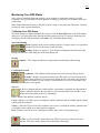
M ONITORING YOUR GPS STATUS........................................................................................................................................ 111
To Monitor Your GPS Status...........................................................................................................................................111
Satellite Info........................................................................................................................................................................112
TRACKING YOUR ROUTE DIRECTIONS................................................................................................................................. 112
To Track a Route................................................................................................................................................................112
5
Table of Contents
A UTOMATIC PAN..................................................................................................................................................................... 113
To Pan the Map Automatically........................................................................................................................................113
LOGGING................................................................................................................................................................................... 114
To Log Your Route.............................................................................................................................................................114
PLAYING BACK A LOG FILE................................................................................................................................................... 114
To Play Back a Log File...................................................................................................................................................114
UPLOADING TO A GPS RECEIVER......................................................................................................................................... 115
To Upload Waypoints, Draw Object Points, and Route Directions..........................................................................115
DOWNLOADING FROM A GPS RECEIVER............................................................................................................................. 115
To Download a Routes, Waypoints, and Track Logs...................................................................................................116
GPS SETTINGS FOR THIRD-PARTY DEVICES....................................................................................................................... 116
To Use Recommended Settings for Your Third-Party Receiver.................................................................................116
ROUTE.........................................................................................................................................................................................118
ROUTE OVERVIEW .................................................................................................................................................................. 118
CREATING A NEW ROUTE ...................................................................................................................................................... 118
To Create a New Route.....................................................................................................................................................118
To Create a Long Route on a Trail.................................................................................................................................119
VIEWING ROUT E DIRECTIONS............................................................................................................................................... 120
To View Your Route Directions.......................................................................................................................................120
EDITING A ROUTE.................................................................................................................................................................... 121
To Edit a Route...................................................................................................................................................................121
IMPORTING ROUTES................................................................................................................................................................ 121
To Import Routes................................................................................................................................................................121
DISPLAYING ROUTES ON THE M AP....................................................................................................................................... 122
To Clear (Hide) a Route from the Map..........................................................................................................................122
To Display a Route on the Map.......................................................................................................................................122
DELETING A ROUTE ................................................................................................................................................................ 122
To Delete a Route ..............................................................................................................................................................122
SAVING A ROUTE..................................................................................................................................................................... 122
To Save Without Exiting the Application.......................................................................................................................122
To Save When Exiting the Application...........................................................................................................................122
U SING A DVANCED ROUTING OPTIONS ................................................................................................................................ 123
To Add, Remove, and Rearrange Route Points............................................................................................................123
To Add Comments..............................................................................................................................................................124
SETTING ROUTING PREFERENCES......................................................................................................................................... 124
To Set Route Preferences..................................................................................................................................................124
To Set Route Features.......................................................................................................................................................125
EDITING ROADS....................................................................................................................................................................... 125
To Edit Roads.....................................................................................................................................................................126
PROFILE.....................................................................................................................................................................................127
PROFILE OVERVIEW................................................................................................................................................................ 127
CREATING A PROFILE ............................................................................................................................................................. 127
To Create a Profile............................................................................................................................................................127
To Profile Multiple Linear Objects.................................................................................................................................128
PROFILING LINEAR OBJECTS................................................................................................................................................. 128
VIEWING THE PROFILE ELEVATION GRAPHS ...................................................................................................................... 128
To View the Profile Graph ...............................................................................................................................................128
To View the Overview Profile Graph.............................................................................................................................129
STATISTICAL DATA OPTIONS ................................................................................................................................................ 130
M ANUALLY SETTING M INIMUM AND M AXIMUM ELEVATION......................................................................................... 130
To Manually Adjust Minimum and Maximum Elevation............................................................................................130
CLEARING A PROFILE ............................................................................................................................................................. 131
To Clear a Profile..............................................................................................................................................................131
MAP DISPLAY..........................................................................................................................................................................132
M AP DISPLAY OVERVIEW...................................................................................................................................................... 132
6
Table of Contents
SETTING M AP FEATURE PREFERENCES................................................................................................................................ 132
To Set Basic Map Feature Preferences..........................................................................................................................132
To Set Custom Features....................................................................................................................................................133
M AP FEATURE OPTION DESCRIPTIONS ................................................................................................................................ 134
Shaded Relief......................................................................................................................................................................134
Contours..............................................................................................................................................................................134
Grids.....................................................................................................................................................................................134
Land Cover..........................................................................................................................................................................134
Map Center Crosshair......................................................................................................................................................134
One Ways.............................................................................................................................................................................134
Places (Minor)....................................................................................................................................................................134
Transportation (Minor).....................................................................................................................................................134
USGS Quadrangle Coverage...........................................................................................................................................135
ZIP Codes............................................................................................................................................................................135
SETTING UNITS OF MEASURE PREFERENCES ...................................................................................................................... 135
Coordinate Preferences....................................................................................................................................................135
Distance Preferences.........................................................................................................................................................136
Bearing Preferences..........................................................................................................................................................136
NETLINK....................................................................................................................................................................................137
NET LINK OVERVIEW .............................................................................................................................................................. 137
U SING THE HOME PAGE ......................................................................................................................................................... 137
U SING THE SOFTWARE PAGE ................................................................................................................................................. 137
U SING THE DATASETS PAGE .................................................................................................................................................. 137
U SING THE SUPPORT PAGE .................................................................................................................................................... 137
LEGAL INFORMATION.......................................................................................................................................................138
DELORME TOPO USA ® 4.0 SINGLE-USER LICENSE AGREEMENT .................................................................. 138
LICENSE TERMS AND CONDITIONS.........................................................................................................................138
U.S. GOVERNMENT RIGHTS IN COMMERCIAL SOFTWARE.............................................................................140
IMPORTANT NOTICES.............................................................................................................................................................. 140
Patent and Copyright Notice...........................................................................................................................................140
U.S. Government Rights in Commercial Software.......................................................................................................140
A PACHE SOFTWARE LICENSE , VERSION 1.1 ....................................................................................................................... 140
7
Welcome
Welcome
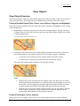
Welcome to Topo USA 4.0
Tip: To view Help, click a book once to read its overview. Double -click a book to read its overview and
view all associated topic pages. Click a topic to view its contents.
With Topo USA 4.0, you can perform the follow ing functions and more:
•
Use the QuickSearch Find feature to locate a city or town, a major point of interest, street address,
ZIP Code, or coordinate point.
•
Use the Advanced Find feature to additionally locate the intersection of two streets, a specific
category of map items (such as landmarks along the current route), or an area code and exchange
within a specified area or along your current route.
•
Use Topo USA 4.0, Sat 10, or 3-D TopoQuads ® data
•
Use the Measure tool to measure linear distance, or the area and perimeter of a polygon
measurement object on the map.
•
Use the split-window functionality to open a secondary map window and view two types of data
for the same location simultaneously. Topo USA 4.0 supports Topo USA 4.0, Sat 10, DOQ, and
3-D TopoQuads ® data.
•
Create direct, trail, and road routes by adding start and finish points on your map. Customize your
route by adding stops and vias.
•
Profile map items and objects you draw/add to the map to determine coordinate information,
linear distance, elevation, grade, and so forth.
•
View 2-D and 3-D terrain with shaded relief, detailed land use/land cover features, and elevation
contours. (The ability to view these features depends on the map data you use with the program.)
•
Customize your map by adding text, MapNotes, stock symbols, and symbols that you design
yourself using DeLorme XSym (provided with Topo USA 4.0).
•
Add your own local roads and trails using the Routable Draw tools. Attach (snap) them to the
existing roads/trails in the program for routing capability.
•
Print high-quality, detailed, 2-D or 3-D single-page maps, mural maps as large as 3 x 3 pages, and
large format maps. Large format printing is only restricted by your printer's or plotter's paper size
and memory capability.
•
Print your routes and/or route directions; and print profiles of routes, roads, or draw objects
(including measure objects).
•
Use the Global Positioning System (GPS) through a connection with a GPS receiver to monitor
your position on the map in real time as you travel. For more information, see Getting Started
with GPS on page 107.
Running Topo USA 4.0
As soon as you have installed Topo USA 4.0, you can read your Topo USA data, Sat 10 data, or data
discs from other DeLorme mapping products such as 3-D TopoQuads ® and previous versions of Topo
USA .
8
Welcome
To Run Topo USA 4.0
Use the following steps to access Topo USA 4.0.
1. Insert a Sat 10, 3-D TopoQuads, or Topo USA 4.0 data disc into your CD/DVD-ROM.
2. If you installed a desktop shortcut, double -click the Topo USA 4.0 icon.
OR
From the Start menu, point to Programs , point to DeLorme , point to Topo USA 4.0, and then
click Topo USA 4.0.
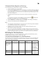
Exiting Topo USA 4.0
To exit the program, click the close button
in the upper-right corner of the screen.
Note : The only time a route is saved is when creating a new project or when you exit Topo USA 4.0. For
more information, see Saving a Route on page 122.
A Save Changes dialog box displays if only one item was changed, such as the zoom level, resulting in a
change to the project.
•
Click Yes to save any changes to the item.
•
Click No to discard changes to the item.
•
Click Cancel to return to Topo USA 4.0. Changes are not saved.
An Exit dialog box displays if more than one item has been updated. All updated files are listed and are
selected by default.
•
Click Save and Exit to save any changes for the selected files and close the program.
Note : Clear the check box of any item you do not want saved prior to using this option.
•
Click Exit without Saving to close the program without saving any file changes.
•
Click Cancel to return to Topo USA 4.0. No files are saved.
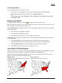
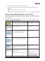
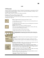
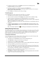
Topo USA 4.0 CD Data Regions
Topo USA 4.0 map data is available on six regional CD-ROMs in addition to the installation disc. DVD
users have all the states available on one data disc in addition to the installation disc.
Note : When working with multiple regional data discs, you may swap discs at any time. The system
prompts you when it needs data from another region.
Region 1Eastern
CT, DC, DE, MA, MD, ME, NH, NJ, NY, OH, PA,
RI, VA, VT, WV, KY
Region 2 Southeast
AL, AR, FL, GA, LA, MS, NC, SC, TN
9
Welcome
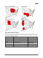
Region 3 Great Lakes and Plains
IA, IL, IN, KS, MI, MN, MO, ND, NE, SD, WI
Region 4 Southwest
AZ, NM, OK, TX
Region 5 Mountain States Region
CO, ID, MT, UT, WY
Region 6 Pacific West
AK, CA, HI, NV, OR, WA
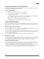
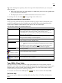
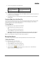
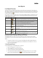
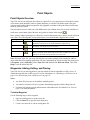
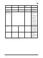
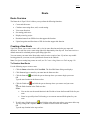
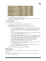
Topo USA 4.0 File Directories
Topo USA 4.0 allows you to save route files, draw files, print files, and so forth in designated directories.
The table below describes the different file types the program supports, which default directory each file
type is saved in, and the file extension(s).
File Type
Dataset Files
Draw files
Export files (Draw)
GPS Log files
Project files
Print files
Default Directory
C:\DeLorme Docs\ImageData
C:\DeLorme Docs\Draw
C:\DeLorme Docs\Export
C:\DeLorme Docs\ GPSLogs
C:\DeLorme Docs\Projects
C:\DeLorme Docs\Print
Route files
Symbol files
Transfer files
C:\DeLorme Docs\Navigation
C:\DeLorme Docs\Symbols
C:\DeLorme Docs\Projects
Extension(s)
.dat (dataset)
.an1
.txt
.gpl
.tp4
.txt (route directions)
.bmp (all other files)
.rtd
.dim
.dmt
10
Welcome
Saving Topo USA Data to Your Hard Disk Drive
Your Topo USA data can be saved to your hard disk drive so that it is readily available without inserting
it into your CD/DVD-ROM drive when you need it.
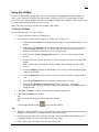
To Save Topo USA Data
Use the following steps to save Topo USA data to your hard disk drive.
1. Insert the Topo USA data disc into your CD/DVD-ROM drive.
2. From the Start menu, click Run.
3. Type D:\Setup (where D: is the letter of the drive containing the data disc) in the command line
text box and then click OK. The Topo USA data setup screen displays.
4. Follow the screen directions to complete the data installation.
5. Click Finish when prompted. It is not necessary to restart your computer.
Frequently Asked Questions
Below is a list of the questions which are asked most frequently by our customers about the Topo USA
family of products. The questions appear in order, with the most frequently asked question at the top of
the list.
How do I create a route on the map?
Topo USA 4.0 allows you to create a straight-line route by simply adding start and finish points. You can
add vias or waypoints to make your route more useful and realistic.
You can also create a route using right-click functionality while in any tab. Your route receives a default
name when creating it using right-click options. However, you can rename your route any time in the
Route tab to make it easier to retrieve.
For more information on adding a route to your map, see Creating a New Route on page 118.
How do I save a route?
Topo USA 4.0 retains the route in memory as it is added, but it is not saved until you exit the program or
save your project within the MapData tab. Routes have .anr extensions and are saved in the C:\DeLorme
Docs\Navigation directory by default. For more information, see Saving a Route on page 122.
How do I find a specific location?
Topo USA 4.0 offers powerful search tools that enable you to locate any place in the United States. You
can search for a specific city/town, feature, point of interest, street address, ZIP Code, area code and
exchange, street intersection, or coordinate location throughout the entire United States.
To access the search feature in Topo USA 4.0, click the Find tab. For more information on searching for
specific locations, see Using QuickSearch on page 32 and Using Advanced Search on page 34.
11
Welcome
How do I transfer waypoints?
With Topo USA 4.0 you can upload and download waypoints between your computer and your handheld
device, if it has that capability. For more information, see the following topics:
•
Uploading to a GPS Receiver on page 115
•
Downloading from a GPS Receiver on page 115
•
GPS Settings for Third-Party Devices on page 116
How do I bring in maps from another DeLorme program?
Routes you create using any of the following DeLorme programs can be brought into Topo USA 4.0: all
versions of Street Atlas USA ®; all versions of Map'n'Go®; all versions of XMap, inc luding XMap
Business and XMap Geographic; all versions of Topo USA; TopoTools 3-D TopoQuads ®; and Map Print
Pack USA.
For more information on how to import routes, see Importing Routes on page 121.
How do I bring in draw files created in another DeLorme program?
Draw files can be brought in from many other DeLorme programs for use in Topo USA 4.0. For a
complete list of supported programs and more information on importing draw files and other files into
Topo USA 4.0, see Importing Files to Draw Files on page 58.
How do I fix the roads on my map?
If you find there is a local road that is missing, you can add it to the current roadlayer file using the
Routable Roads Draw tool. For more information, see Routable Roads: Drawing, Editing, and Placing on
page 71.
Can I design my own symbols to use with Topo USA 4.0?
You can use DeLorme XSym to create and edit custom symbols, then apply these symbols to the maps in
Topo USA 4.0. For more information, see Adding Your Own Symbols to Your Map on page 98.
To open DeLorme XSym, from the Start menu, point to Programs , point to DeLorme , point to Topo
USA 4.0, and then click DeLorme XSym.
Tip: Click Help on the DeLorme XSym screen for additional information.
How do I initialize my GPS receiver?
Each time you use your GPS receiver, you initialize it, which means you set your starting position on the
map by obtaining the initial coordinates of your location. This can be done automatically or manually.
For more information, see Getting Started with GPS on page 107 and Initializing GPS on page 107.
How can I get information about an item on the map?
You can right-click virtually any point, symbol, feature, or area on the map and then click Info to identify
it and view detailed information about it. The type of descriptive information varies, depending on the
item you have right-clicked.
You can also copy the information and paste it into another program, such as a word processor.
12
Welcome
What is a project?
Topo USA 4.0 lets you save all of the work you have done in the mapping application as a single
workspace so you can open it again later. These saved workspaces are called projects.
A project consists of the following items: coordinates of the map center, current zoom level, current
magnification, map display preferences, any added items: such as draw file(s), route(s), and so forth. As
you create new routes or draw files, change preferences, or pan/zoom the map, these changes are added to
the current project. Changes can be saved or discarded.
To learn how to create a project in Topo USA 4.0, see Creating and Deleting Projects on page 52.
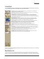
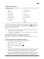
What do the different colors and symbols on the map mean?
The different colors on the map represent different areas of land use or land cover (for example: parks,
population areas, water, forests, parks, and so forth). The Map Legend provides examples and
descriptions of these and other map features as they display on Maps in Topo USA 4.0.
To display the Map Legend Help topic, click the Help button
in Topo USA 4.0 and then click
MapLegend. You can view the Map Legend for all features on the map or view the legends for
individual feature categories.
How do I zoom in for a closer view of the map?
You can use the Zoom tools to quickly change the zoom level (2-0 to 15-0) of the map view. Increasing
the zoom level number shows a smaller area at greater detail. Decreasing the zoom level number shows a
larger area at lesser detail.
For more information, see Zoom Level on page 30 and Zooming In and Out on page 31.
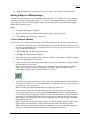
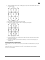
How do I find all landmarks within ten miles of a specific location on the map?
You can find all landmarks (or other categories of items) within a 10 mile radius of the map center using
the Find tab.
•
Center the place or item you want to use as the center of your search on the map view.
•
Click the Find tab and then click Advanced.
•
From the Find drop-down list, select Category.
For more information on category searches, see Keywords for Category Searches on page 36.
Note : In all category searches, the Keywords field is optional. If the Keywords field is left blank,
all objects in the selected Within area display in the Results list.
•
From the Within drop-down list, select Distance from Map Center.
•
Type the desired distance in the text field to the right of the Find and Within fields.
Note : The minimum distance which can be used is 50 feet; the maximum distance is 100 miles.
•
Click Search or press the ENTER key on your keyboard. The Results list displays your search
results with closest match items at the top of the list.
•
Scroll (or browse) through the list of search results until you find the item(s) you want to view.
To center an item on the map, double -click it.
Note : For more information, see Tips on Viewing Find Results on page 39.
13
Help
Help
Help Overview
There are several ways to get more information on Topo USA 4.0 features and functionality.
On-Screen Help
Help is available in the dialog area of Topo USA 4.0 in the form of ToolTips and information boxes. For
more information, see On-Screen Help on page 16.
Help Menu
Click the Help button
on the title bar to view the online Help options available with Topo USA
4.0. Then, clic k an item to select it.
Tip: To access a Help menu item using its underlined letter, click the Help button and then press the
underlined letter (for the desired item) on your keyboard. For example, to access the Map Legend, click
the Help button and then press the M key on your keyboard.
Context-Sensitive Help
Click the context-sensitive Help button
using.
to receive overview Help information for the tab you are
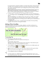
Using the Help System
This Help system provides explanations of all of the features and functions of Topo USA 4.0. To access
the Help system, click the Help button
on the title bar and then click Help Topics , or press the F1
key on your keyboard.
The Help system displays four tabs. Click the name of a tab below for more information on how to use
that tab.
Contents
To view an outline of the Help system contents, click the Contents tab.
•
To view the overview for a particular book, click the book.
•
To view the additional topics under a particular book, double -click the book.
•
To view a topic, click the desired page.
Index
Use the following steps to search the Help system index.
•
While in the Help system, click the Index tab.
•
Type a keyword in the entry field. The list automatically scrolls to the closest matching entry.
•
Double-click the desired topic.
OR
Click the topic and then click Display.
OR
Click the topic and press the ENTER key on your keyboard.
Notes:
14
Help
•
If a topic has any secondary index references, a window displays the secondary index options.
Click the item of interest to display the topic.
•
If you don't find what you're looking for in the index, click the Search tab and try a search for
your keyword.
Search
Use the following steps to search for particular words or phrases within topics in the Help system.
•
While in the Help system, click the Search tab.
•
Type a keyword in the entry field and then click List Topics or press the ENTER key on your
keyboard. A list of topics containing the keyword displays.
•
Double-click the desired topic under Select Topic to Display.
OR
Click the topic and then click Display.
OR
Click the topic and press the ENTER key on your keyboard.
Glossary
There is a small glossary containing mapping coordinate, GPS, and other terms that you may find helpful.
To view a glossary term, use the following steps.
•
While in the Help system, click the Glossary tab. If the Glossary tab is not in view, use the
horizontal scroll buttons to the right of the tabs to locate it.
•
Scroll through the Terms list to view the available terms and click the one you want more
information about. The definition displays under Definition For at the bottom of the screen.
•
To view another definition, click another term.
Notes:
•
The Help system keeps a history of viewed topics. Click the Back button
backward through previous topics. Click the Forward button
the topics previously viewed.
•
to browse
to browse forward through
Print any of the Help Topics by selecting a topic or heading (next to the book symbol) and then
clicking the Print button
. You can choose to print only the selected topic or a heading
and all subtopics.
OR
Right-click the topic displaying in the right window to print only that topic.
15
Help
Tip: Before clicking Print, expand any links in the topic which include information you want to print
within your topic.
•
While in the Help system, the pointer changes to a hand when it passes over text or graphics that
you can click for more information.
•
The Help Topics window is a standard window that can be moved or resized.
To exit Help, click the close button
in the upper-right corner of the screen.
Help Documentation Conventions
To help you easily locate and interpret information, this Help system has been formatted with various
words in all capital letters, in color, in boldface type, and so forth. There are also hyperlinks which
expand, jump to another location within the same topic, or link you to other topics.
The table below defines each convention and its use.
The convention...
ALL CAPITALS
Bold
Italic
Blue underlined text
Red underlined text
Is used for...
Acronyms, names of certain commands, and keys on the keyboard.
Note: Use of the plus sign (+) between key names indicates key combinations
which perform various actions. For example, in the directions "Press
CTRL+SHIFT+F3 on your keyboard," you must press and hold the CTRL and
SHIFT keys while pressing F3.
Command buttons, tab names, and options when used in procedures and exercise
steps. Also used for information that you type exactly into a particular field.
Headings and table headings are bold for emphasis.
Directory names and paths; used sparingly for emphasis; also used when referring
to titles of chapters, sections, and publications.
Hyperlinks. These links act differently depending on their context. When it is:
• Referenced with "for more information," the link always goes to another
topic.
Embedded in text, such as in the example "Open the file," the link either goes to
another topic or displays a secondary window with a definition or graphic.
Drop-down text which expands within the same topic to reveal more information
(such as a procedure).
A note that applies to the entire Help topic. If there is more than one note, the Notes
symbol is used and the notes are bulleted.
symbol in a yellow
box
Note(s): in Yellow Highlight A note within a procedure. If there is more than one note, the notes are bulleted.
A tip that applies to the entire Help topic. If there is more than one tip, the Tips
symbol is used and the tips are bulleted.
symbol in a blue box
Tip(s): in Blue Highlight
A tip within a procedure. If there is more than one tip, the tips are bulleted.
Topo USA 4.0 User Guide
The Topo USA 4.0 User Guide is the same as the printed manual you received with the product. It
includes the entire Help system contents, modified for print format, in a portable document format (.pdf).
When the guide is accessed, Adobe ® Acrobat® Reader launches. The User Guide contains a table of
contents and can be printed out as a hard-copy reference.
To access the User Guide, click the Help button
on the title bar and then click User Guide .
On-Screen Help
There are two ways to obtain on-screen Help while using Topo USA 4.0: ToolTips and information
boxes.
16
Help
ToolTips
When you point to any of the Topo USA 4.0 tools for a few seconds, a short label (ToolTip) displays on
your screen describing the tool. ToolTips also display in Topo USA 4.0 windows and dialog boxes when
you point to a button, icon, or other feature.
Information Boxes
Several of the Topo USA 4.0 tabs contain information boxes that often display to the left of the Overview
Map (the small map in the lower-right corner of your screen). Information boxes provide descriptions
about the features and functions of the selected tab.
17
Basic Functions
Basic Functions
Basic Functions Overview
Map control in Topo USA 4.0 is accomplished by using standard mouse point-and-click functionality and
the Control Panel tools. Right-click options provide flexibility for labeling, routing, getting information,
and so forth. For more information, see other Basic Functions topics. If they are not currently displaying,
double-click the Basic Functions book.
To Control the Map
The following list details the basic functions for controlling map movement.
•
The mouse is used to pan or center the map view. Click a spot on the map to center the map on
that point.
•
A white hand displays when you point near the edge of the map. When the hand is visible, drag
the map in the desired direction.
•
Use the black view box in the Overview Map window to pan the map. Point anywhere on the
view box. When the pointer becomes a
•
, drag the view box to the desired location.
The mouse button also allows you to quickly zoom the map using drag and zoom functionality.
To Use the Tabs
Click on a tab to view the available functionality. You can also use the keyboard arrow keys to browse
through the tab areas. If it is not possible to display all tabs, horizontal scroll arrows display to the right of
the last visible tab.
Drag and Zoom
One of the most convenient features of Topo USA 4.0 is the ability to quickly zoom in on the map by
using drag and zoom functionality. Zoom in by dragging the mouse in a down-right direction or zoom out
by dragging the mouse in an up-left direction.
To Zoom In
Zooming in increases the zoom level number and shows a smaller geographic area at greater detail. The
maximum zoom-in level at which data can be viewed is 15-0. For topographical datasets, the continental
United States displays up to zoom level 15-0 and Alaska displays up to zoom level 15-0.
Use the following steps to zoom in.
1. Drag the mouse in a down-right direction on the map to encompass the area you want to display.
A view box displays on the screen and changes dimension as you move the mouse. A label
displays the zoom level at the current map center.
2. Once you reach the desired area or zoom level you want to display, release the mouse button. The
area you selected fills the map window, the map re-centers, and the map view adjusts to show the
appropriate level of detail.
Tip: You can move the view box to another location by pressing the SHIFT key at anytime
during this procedure.
To Zoom Out
Zooming out decreases the zoom level number and shows a larger geographic area at lesser detail. The
maximum zoom-out level is 2-0.
18
Basic Functions
Use the following steps to zoom out.
1. Drag the mouse in an up-left direction on the map. A staircase with a small square displays on the
screen.
2. Continue dragging the mouse in an up-left direction. The small square moves up the steps, one
step per zoom level. A label displays the zoom level to the bottom-right of the staircase.
3. Once you reach the desired zoom level you want to display, release the mouse button. The map
view adjusts to display the appropriate level of detail. The map center is retained on your screen.
Note : Additional zoom features include the Zoom Level controls and the Zoom tools.
Panning/Centering the Map
You can use any of the following methods in Topo USA 4.0 to pan (move) or center the map.
•
Click anywhere on the current map view. The point at which you click becomes the new map
center.
•
When you point near the map edge, a white hand displays. Drag the hand to scroll the map in the
desired direction.
•
Click anywhere on the Overview Map. The point where you click becomes the new map center.
This technique allows you to traverse greater distances with each mouse click than you can within
the main map.
Note : If the Overview Map, the small map in the lower-right corner of the screen, is not
displaying, pan or zoom the map.
•
Point anywhere on the black view box in the Overview Map window. When the pointer becomes
a
, drag the view box to the desired location.
•
Use the Find tab to center the map on a particular location.
•
Press ALT+ an arrow key (up, down, left, or right) to pan the map view in small increments in the
desired direction.
•
While the Num Lock key is off, you can use the direction keys on your numeric keypad to move
the map. Press:
o
ALT+UP ARROW to pan the map up.
o
ALT+RIGHT ARROW to pan the map right.
o
ALT+DOWN ARROW to pan the map down.
o
ALT+LEFT ARROW to pan the map left.
Note : Verify the Num Lock key is off by checking that the Num Lock indicator light is turned off.
19
Basic Functions
Control Panel
The Control Panel, located to the right of the map view, displays information pertinent to the current map
view and map cursor position. It also includes zoom and map pan buttons.
Zoom Level—The current zoom level of the map view; ranges between 2-0 (maximum
zoom-out) and 20-0 (maximum zoom-in).
Zoom Tools—Buttons that quickly zoom out three levels, out one level, or in one level. For
more information, see Zooming In and Out on page 31.
Compass Rose—A group of nine buttons, eight with yellow arrows pointing outward.
Click one of the arrow buttons to pan the map in that direction. Click the middle button to
center the map on the previous map view. This button performs an undo function for the last
pan or zoom (up to 256 times).
Map Rotation Tool—This drop-down list is used to change the orientation of the map
display by adjusting the degree of map rotation. The angle of map orientation is directly
related to the degrees of a compass; for example, 90 degrees is always East.
Map Coordinates—Coordinates for the current map cursor position display based on the
units chosen under Coordinates on the Units dialog area in the Map Display tab.
Elevation and Interval—These distances display in statute miles, with smaller
measurements displaying in feet. Zoom level affects interval display.
Magnify—Reduce or enlarge (50200%) the current map view image much like a
photocopier. Although the size of the image changes, the amount of geographic detail does
not.
Split Window—Button which displays/hides the secondary map window. Lets you display
two sets of data for the same area simultaneously. You can control which dataset displays in
the primary and secondary map windows via the MapData tab.
Measure Tool—Measure linear distances and perimeter/area on the map. For more
information, see Measuring Distance and Area on page 21.
Scale Bar—Indicates the distance one scale bar unit equals in the measurement chosen
under Measures on the Units dialog area in the Map Display tab.
Note : For information on changing coordinate systems or distance measures, see Setting Units of Measure
Preferences on page 135.
Map Rotation Tool
Topo USA 4.0 allows you to change the orientation of the map display by adjusting the degree of map
rotation. The angle of map orientation is directly related to the degrees of a compass; 90 degrees is always
20
Basic Functions
East, 135 degrees is Southeast, 180 degrees is South, and so forth. For example, when you select 90
degrees from the drop-down list, the map rotates so that 90 degrees (East) is at the top of the screen.
To Change the Map Rotation
Use one of the following two methods to change the angle of map rotation.
•
Select an angle from the available drop-down list
(in 45 degree increments)
OR
•
Type a specific angle (from 0 to 359 degrees) in the entry field.
Notes :
• The black rectangle in the Overview Map window, indicating the current map view, also rotates
to match the angle of map rotation.
•
A rectangle drawn with the Polygon/Rectangle/Circle tool in the Draw tab is positioned in
relation to North.
Measuring Distance and Area
The Measure Tool allows you to measure linear distance and area on the map based on the units chosen
under Coordinates on the Units dialog area in the Map Display tab.
The snapping feature allows you to snap (attach) the point of a measurement line to a point on a road or
trail or another measurement object. Using the snapping feature helps to ensure a more accurate
measurement of distance or area.
The snap function is essential when measuring area. To measure area, you must completely enclose the
desired area by snapping your finish point to your starting point. For more information, see the procedure
which immediately follows.
To Measure Distance or Area
Use the following steps to measure linear distance or area on the map.
1. Verify you have the desired units of measure selected in the Map Display tab. For more
information, see Setting Units of Measure Preferences on page 135.
2. On the Control Panel, click the Measure Tool
. The pointer changes to a
.
3. Click point-by-point to draw a measurement line on the map. A text box displays next to your
pointer indicating the total distance of the measurement taken.
Note : When you pass over a point in a road or trail, measurement line, or measurement area to
which you can snap, a yellow circle defines the snap point. Click to snap the point of the
measure line to the road or measurement object's point coordinate.
4. To end a measurement line, double -click the last point of the measurement line. The measure line
displays as a two-pixel wide yellow line and the total length of the line displays in a label at each
endpoint of the line.
5. To end a measure area, hover over the starting point until the yellow snap circle displays and
then double -click the last point to the starting point. The closure area becomes transparently
shaded, and the area and perimeter measurements displays.
Tip: Instead of double -clicking to end measure mode, click the last point of your measure line or area and
then click the Measure Tool
.
21
Basic Functions
Notes:
•
Measure objects (lines and areas) are saved with the current project. When a new file is created,
the measure objects do not display. If you want the same measure objects on your new project,
you must recreate them.
•
When you right-click a measure object, a shortcut menu displays Delete Measurement and Copy
to Draw Object options. For more information, see Right-Click Mouse Options on page 24.
Using the Overview Map
The Overview Map is a smaller map in the lower-right corner of the screen, which offers a wide-angle
view of your current map view area. It is approximately three zoom-levels out from the current map view.
The Overview Map displays at all times, unless you have performed a right-click option to get
information about a map feature. If the Overview Map is not displaying, you can activate it by panning
the map or changing the zoom level.
Tips :
•
Click anywhere on the Overview Map and that point becomes the new map center. This technique
allows you to travel greater distances with each mouse click than you can within the larger,
current map view.
•
Use the black view box in the Overview Map window to pan the map. Point anywhere on the
view box. When the pointer becomes a
, drag the view box to the desired location.
Using the Secondary Map
Topo USA 4.0 has split-window functionality which lets you open a secondary map window to view a
second set of data simultaneously. The secondary map displays in the left window and the primary map
displays in the right window.
The secondary map displays when you click the split-screen button
on the Control Panel.
Accessing Data Collections
When the split-window feature is activated, a bar displays on the top of the secondary map (see graphic
below). This bar displays two drop-down lists: one for swapping data and one for changing the map from
2-D to 3-D (and vice versa). The bar also has zoom tools which work specifically with the secondary map
window. All of the data collections that you have saved to your hard disk drive are available from the data
drop-down list.
Note : For more information about saving data to your hard disk drive, see Saving Topo USA Data to Your
Hard Disk Drive on page 11 or the "How Do I View Multiple Datasets With One CD-ROM Drive?"
section in MapData Overview on page 51.
22
Basic Functions
Note: The graphic above displays Sat 10 data, available separately from DeLorme.
Additional Facts About Split-Screen Functionality
The following list details split-window functionality and the interaction between the primary and
secondary map windows.
•
Both windows are centered on the same coordinate position. Panning or rotating the primary map
using the tools in the Control Panel causes the same action on both maps.
•
Using drag and zoom functionality or scrolling the map in the primary window changes the map
in the secondary window as well. Scrolling the secondary map also causes the primary map to
pan.
•
Using drag and zoom on the secondary map also affects the primary map.
•
The secondary window has its own zoom level controls. You can change the zoom level of the
secondary map without affecting the zoom level in the primary window. However, after you have
adjusted the zoom level in the secondary window, the zoom tools on the Control Panel adjust the
map incrementally. In other words, if the secondary map is at zoom level 6-0 and the primary
23
Basic Functions
map at zoom level 8-0 and you click the Zoom Out 1 tool, the secondary map displays at zoom
level 5-0 and the primary map at 7-0.
•
You can use the measure tool
in either window and any line or polygon measured in one
window also displays in the other window.
•
The Overview Map is always associated with the primary window and only displays the visible
primary map data.
•
Other tab functionality may be affected by use of the split-screen function. The following list
describes impacts to other tabs in Topo USA 4.0.
o
Draw—The line, polygon, and highlighting draw tools work in either window. The
Select tool
highlights the same draw object on both maps and you can then
manipulate "both" objects at the same time. Draw files are created for both windows in
the same project.
o
Route—You can create routes only in the primary window; routes do not display in the
secondary window.
o
GPS—You can log with GPS in the primary window; log playback displays in both
windows.
o
Profile —You can only create profiles in the primary window.
o
3-D—The 3-D map always displays in the secondary map window.
o
Map Display—Settings selected in the Map Display tab affects the maps in both frames.
Right-Click Mouse Options
Right-click mouse options in Topo USA 4.0 make many functions more convenient. For example, you
can add and delete routes without going to the Route tab, add MapNotes without going to the Draw tab,
and so forth.
Click the right mouse button while pointing to a draw object, road, river, city, or other map feature. A
shortcut menu displays near the selection point with the options available for that particular map feature.
Note : If there are multiple (layered) objects on the point that is right-clicked, additional menu options
corresponding to the map objects are available.
Add MapNote
The Add MapNote right-click option allows you to label map locations with various types of MapNotes.
Right-click the point on the map you want to label, point to Add MapNote , and then click one of the
available options.
Each MapNote type provides different information, as shown in the following table.
MapNote Type (Color)
MapNote (light blue)
Not always available.
MapNote Label Information
Name of feature or its type, if unnamed.
Note: If there is no feature type, no MapNote displays. This is
most noticeable when right-clicking on land only, indicated by
.
Detailed MapNote
Name, feature name, feature category, and measurement
(light blue)
information, for example: Great Cranberry Island, Land or
Not always available.
Island, Earth Surface, 1.71 square miles.
Where Am I MapNote (light blue) City, county, and state names, plus the ZIP Code.
Coordinate MapNote (light blue) Coordinate information, based on the current coordinate format
chosen in the Map Display tab.
24
Basic Functions
MapNote Type (Color)
Blank MapNote (white)
MapNote Label Information
A blank label, which you can edit yourself.
Note : Once a MapNote is added, its anchor point cannot be moved. However, the text area can be
repositioned. For more information, see To Move Right-Click MapNotes on page 29.
Convert to Waypoint/Via
This option is available when you right-click a waypoint or via on a route. It allows you to switch the
selected point from a waypoint to a via, or vice versa.
Tip: To view existing Vias on your route, click the Route tab, click New/Edit, and then click the Via tool
.
Copy to Draw Object
This option copies a line directly on the selected item. By using options in the Draw tab, you can select
and then move and/or manipulate the linear object. For example, you can extend a trail off-road by
dragging the draw object's endpoint in the direction of travel. Or, you can use a road as one edge of a
polygon shape, by dragging its shape points into the desired configuration.
Map lines which can be copied to Draw objects include all types of roads and highways, trails, railroad,
power lines, pipelines, rivers or streams, and grid lines. This option is also available for measure objects
(line and area).
Delete Options
The delete options on the shortcut menu vary based on the type of item you right-click.
•
When you right-click a Draw object (such as a line, polygon, or MapNote, and so forth) and then
click Delete Draw Object, the object is deleted from the draw file .
•
When you right-click a measure object (line or area) and then click Delete Measurement, the
object is deleted from the project.
•
When you right-click any route point (start, waypoint, via, or finish points), a delete option
specific to the item selected is available (such as Delete Via). A Delete Route option is also
available.
•
When you right-click a route (not on a route point), a Delete Route option is available.
•
When you right-click a Find MapTag, a Delete MapTag option is available.
Edit Draw Object
To make changes to symbol or MapNote text, right-click the desired item and then click Edit Draw
Object.
25
Basic Functions
Info
Right-click a point, symbol, feature, or area on the map and then click Info to identify it and view detailed
information about it. This information displays in the Overview Map area, to the right of the tabs.
Notes:
•
The type of descriptive information varies, depending on the item you have right-clicked. You
can also copy the information and paste it into another program, such as a word processor.
•
If there is more than one object under the point you clicked, information for each object displays.
•
Pan or zoom the map to view the Overview Map.
Profile/Add to Profile
Profile or Profile Route
The Profile right-click option highlights the selected route, road, trail, or Draw object. The Profile tab
displays the selected item's cross-sectional elevation profile.
Note : Profile Route displays only when a route point (start, waypoint, via, or finish) is right-clicked.
Add to Profile
An item must be profiled before this menu option is available.
•
Right-click a map feature and then click Profile . The Profile tab displays the selected item's
cross-sectional elevation profile.
•
To add another line or road segment to an existing profile, press the SHIFT key on your
keyboard, right-click the object you want to add to the profile, and then click Add to Profile. The
new object is added to the currently displayed profile.
Note : If the added line is not adjacent to the lines already profiled, a straight line is drawn between the
end point of the profiled road segment and the one being added to the profile.
Route: Create Route Options
You can use Create Route right-click options from any tab. Right-click a point on the map and then select
one of the options in the table below.
Note : Once set, route points for the active route can be repositioned or re-sequenced. For more
information, see Editing a Route on page 121.
Routing option
Set as Start
Add Waypoint
Add Via
Insert Waypoint
Insert Via
Set as Finish
Function
Sets the selected point as the starting point of your route.
Adds a numbered waypoint to your route. All new waypoints are added in
sequence.
Adds a numbered via to your route. All new vias are added in sequence.
Inserts a waypoint geographically within your route. (If the Automatic
Calculation check box is selected in the Route Prefs dialog area, under Advanced
in the Route tab, the route automatically recalculates based on shortest distance
between each waypoint.)
Inserts a via geographically within your route. (If the Automatic Calculation
check box is selected in the Route Prefs dialog area, under Advanced in the Route
tab, the route automatically recalculates based on shortest distance between each
stop.)
Sets the selected point as the endpoint of your route.
26
Basic Functions
Route: Activate, Hide, Delete, and Profile Route Options
•
To activate an inactive route, right-click the desired inactive route and then click Activate Route .
•
To hide a route, right-click the route and then click Hide Route.
•
To delete a route, right-click the route and then click Delete Route.
•
To view a cross-sectional, elevation profile of your route, right-click the route and then click
Profile Route.
Right-Click Options in the Find Results List
After performing a QuickSearch or an advanced search, you can right-click an item in the Find results list.
A shortcut menu displays the following options.
Copy to Clipboard—Copies the information for the selected item(s) and makes it available for pasting
into another program.
Go To—Provides the same result as clicking the Go To button.
Add MapTag—Adds a MapTag to the selected item(s). Not available if the MapTags check box is not
selected.
Select All—Selects all items in the list and highlights them on the map (up to 50). The Go To button
name switches to Add Tags. Click Add Tags to add MapTags to all selected items. Or, if you right-click
again (with all items selected), you can select Copy to Clipboard or Add MapTags.
Getting Information About Map Features
You can right-click a point, symbol, feature, or area on the map to identify it and view detailed
information about it. The type of descriptive information varies, depending on the item you have rightclicked. You can also copy the information and paste it into another program, such as a word processor.
To Get Information About a Map Feature
Use the following steps to get information about a partic ular map feature.
1. Right-click the desired map feature, such as a road, trail, or town. The right-click options
available for that type of feature display.
2. Click Info. A description displays in the Overview Map display area (lower-right corner of your
screen).
Note : Descriptive information may include a name or feature type, distance, ZIP Code, town
name, county name, state, coordinates, available radio stations, and so forth.
3. To restore the Overview Map, pan or zoom the map.
To Copy Map Feature Information into Another Program
Use the following steps to copy the data in the information box and paste it into another program, such as
a word processor.
1. Select the desired text by dragging across it.
OR
If you want all the information in the box, right-click the information box and then click Select
All.
2. Copy the data by pressing CTRL+C on your keyboard.
OR
Right-click the information box with the selected text and then click Copy.
27
Basic Functions
3. Open or switch to the program where you want to paste the text.
4. Click to select the location where you want to paste the text and then press CTRL+V on your
keyboard.
OR
Right-click the selected location and then click Paste.
OR
If the program you are pasting information into has a menu bar, under the Edit menu, click Paste .
Moving or Deleting MapTags, MapNotes, and Text Labels
There are several types of tags, notes, and text labels used in Topo USA 4.0. Once these are created, you
may forget where and how you generated these items, which is important to know when you want to edit,
move, or delete them.
Use the following table to determine what type of item you have, read a short description, and find more
information on moving, deleting, and editing.
Type of item
MapTag
MapNote
Description
A MapTag displays at the location where a place,
street address, feature type, coordinate, and so forth
are located using the search function in the Find
tab.
A MapNote created using right-click functionality,
it provides the feature name.
For more information
See MapTags: Moving, Hiding, and
Deleting on page 33.
See To Move Right-Click MapNotes
on page 29.
Detailed MapNote
A MapNote created using right-click functionality, See To Move Right-Click MapNotes
it provides the name, feature name, feature
on page 29.
category, and measurement information.
Where am I
MapNote
A MapNote created using right-click functionality, See To Move Right-Click MapNotes
it provides the city/town name, county name and
on page 29.
code, state name and abbreviation, and ZIP Code.
Coordinate MapNote A MapNote created using right-click functionality, See To Move Right-Click MapNotes
it provides the coordinate position based on the
on page 29.
current Units preference selected in the Map
Display tab.
Blank MapNote
You can label your map with a MapNote you edit
yourself by using:
Right-click functionality
OR
The MapNote/Text Label tool in the Draw Tab.
Text Label
You can label your map with a text label you can
See To Move Right-Click MapNotes
on page 29.
OR
MapNotes: Adding, Editing, and
Placing on page 100.
Note: To edit the text, right-click the
blank MapNote, click Edit Draw
Object, and then edit the text.
See Text Labels: Adding, Editing,
28
Basic Functions
Type of item
Description
edit yourself by using the MapNote/Text Label tool
in the Draw Tab. Text labels do not have a
background color like other map labeling items.
For more information
and Placing on page 101.
Note: To edit the text, right-click the
blank MapNote, click Edit Draw
Object, and then edit the text.
To Move Right-Click MapNotes
Use the following steps to move the text area of a MapNote, a Where Am I MapNote, a Coordinate
MapNote, or a Blank MapNote created using the right-click functionality.
1. Click the Draw tab.
2. Click the Select tool
.
3. Click the MapNote to select it.
4. Drag the text area to the desired location.
Resizing the Map and Tab Areas
The Tab and Overview Map windows in Topo USA 4.0 default to 20% your computer's screen height.
These windows can be resized horizontally and vertically (to a maximum of 40% screen height) using the
three resize buttons, a drag method, or the F11/F10 keys.
Notes:
•
The Tab and Overview Map window size is retained when you choose another tab.
•
If it is not possible to display all tabs, horizontal scroll arrows
last visible tab.
•
Some tab areas which provide search results automatically resize depending on the number of
results.
display to the right of the
To Resize the Map and Tab Area Using the Resize Buttons
There are three Resize toggle buttons, which switch to the opposite function once they are clicked. The
following table shows each Resize button, provides its name, and describes its function. Each button is
immediately followed by its toggle opposite.
Button
Button Name
Button Function
Increase to Maximum Maximizes the tab area. All tabs are in view and the information area
Width
widens. The right and left scroll arrows do not display and the Overview
Map is very narrow.
Decrease to Normal Restores the tab area to its default size. Right/Left scroll arrows and the
Width
Overview Map display.
Decrease to Minimum Displays a minimum view of the tab names.
Height
Increase to Normal
Increases to the 20% screen height size.
Height
Note: You can also double-click the horizontal border to increase the screen
height size to 20%.
Increase to Maximum Increases to the 40% screen height size.
Height
Decrease to Normal Decreases to the 20% screen height size.
Height
Note: You can also double-click the horizontal border to decrease the screen
height size to 20%.
29
Basic Functions
To Resize the Map and Tab Area Using the Drag Method
The drag method can be used to resize these areas horizontally or vertically. Use the following steps to
resize using the drag method.
1. Point to the frame area between the Tab and Overview Map windows. The pointer becomes a
.
OR
Point to the horizontal edge of the Tab or Overview Map window. The pointer becomes a
.
2. Drag to resize.
3. To cancel the resize while dragging, press the ESC key on your keyboard. The size just prior to
this resize is restored.
To Resize the Map and Tab Area Using Function Keys
Press the F11 key on your keyboard. Your pointer becomes a
and is repositioned to the top of the Tab
and Overview Map windows, centered over the frame between the two windows. Move your mouse to
resize to the desired height and width. Click the mouse once when done.
To return to the default Tab and Overview Map window size, press the F10 key on the keyboard or
double-click each border.
Note : You can use the arrow keys on the keyboard to resize, after pressing the F11 key on your keyboard.
When done, press the ENTER key on your keyboard.
Zoom Level
Topo USA 4.0 uses zoom levels between 2-0 (maximum zoom-out) and 20-0 (maximum zoom-in, in
most instances). The exceptions is Alaskan data in topographical datasets (15-0 is maximum zoom-in
level). Street-level detail is available at 13-0.
Zoom level, referred to as magnitudes in DeLorme mapping programs such as Topo USA 4.0, has to do
with the relationship between what you see in a map view and how it exists in reality. It is the amount of
geographic data displayed on a computer monitor or handheld device screen. Developed by DeLorme, the
use of magnitudes is similar to the traditional fractional relationship expressed on paper maps (for
example, 1:24,000, 1:100,000, 1:500,000, and so forth).
To Change Zoom Level Using the Zoom Level Tool
The Zoom Level tool is located on the Control Panel, to the right of the map view.
Click the up arrow to zoom out one octave at a time. As you zoom out, you see a larger geographic area
with less detail. Zoom level 2-0 displays the entire United States.
Click the down arrow to zoom in one octave at a time. You can continue zooming in to the maximum
zoom level.
Tip: Use the Zoom In 1 tool
and watch as state routes, local roads, trails, smaller towns, lakes and
rivers, points of interest, and so forth begin to display on the map.
30
Basic Functions
Zooming In and Out
With Topo USA 4.0, you can use the Zoom tools to quickly change the zoom level of the map view.
Increasing the zoom level number shows a smaller geographic area at greater detail. Decreasing the zoom
level number shows a larger geographic area at lesser detail.
To Zoom In/Out Using the Zoom Tools
Use the Zoom Tools shown below to zoom quickly.
Click the Zoom In 1 tool to increase the detail number to the next full level.
Note: This tool is unavailable at zoom level 15-0 in most instances. The exception is Alaskan data in
topographical datasets (lower).
Click the Zoom Out 1 tool to decrease the detail number to the next full level.
Note: This tool is unavailable at zoom level 2-0.
Click the Zoom Out 3 tool to decrease the detail number by three full levels.
Note: This tool is unavailable at zoom level 4-0 or below.
Tip: You can also change the zoom level by using any of the following methods:
•
Use the up and down arrows on the Zoom Level tool in the Control Panel.
•
Use drag and zoom functionality. Drag down-right on the map to zoom in or up-left to zoom out.
•
Press ALT+PAGE UP on your keyboard to zoom out to the next full zoom level. Press
ALT+PAGE DOWN on your keyboard to zoom in to the next full zoom level.
31
Find
Find
Find Overview
There are two Find options you can use to search for and locate places and other map items in Topo USA
4.0: the QuickSearch and the Advanced functions.
•
QuickSearch—Search for places, addresses, ZIP Codes, and coordinate positions. If the item you
are looking for is not recognized, the Advanced tab displays automatically.
•
Advanced—Control what you are looking for via the Find field, and where you are looking for it
via the Within field while you conduct a more detailed search.
Using QuickSearch
Use QuickSearch to locate places, addresses, ZIP Codes, and coordinate positions.
Notes:
•
If the item you are looking for is not recognized, the Advanced dialog area displays
automatically.
•
To search for other items, such as an area code and exchange, street intersection, or a category
(such as Park, Interstate, and so forth), use the Advanced search capability provided in Topo USA
4.0.
To Search for a Place, Address, ZIP Code, or Coordinate
Follow the steps below to use QuickSearch.
1. Click the Find tab and then click QuickSearch.
2. Under Search For, type a name, address, ZIP Code, or coordinate.
Note : Do not enter more than five digits for a ZIP Code search.
3. Click Search. If your search is:
•
Very Successful—The results list displays and, if there is one excellent match, the map
centers on that place and a MapTag displays if the MapTag check box is selected.
Note : The only time a MapTag is not placed is when you find and then go to a labeled
area that has no single map point associated with it; for example, a large park.
•
Successful—The results list displays. Scroll (or browse) through the list of search results
until you find the one you want to locate. To center an item on the map, double -click it or
select it and then click Go To. A yellow MapTag displays at the location if the MapTags
check box is selected.
Tip: Single click an item in the results list if you want to highlight it on the map without
adding a MapTag or centering it in the map view. It must be in the current map view,
however. For more information on viewing results, see Tips on Reviewing Results on
page 39.
•
Not Successful—The Advanced dialog area displays. Topo USA 4.0 makes its best guess
about the type of search you were trying and your search word(s) display in the upperright text box. For more information, see Using Advanced Search on page 34.
32
Find
Notes:
•
Use a comma to separate city and state (Atlanta, Georgia), point of interest and state (Space
Needle, WA), parts of an address (444 E Pk Drive, Milford, CT or 444 E Pk Dr, 06460), or
coordinate points (N 43.8, W 70.2).
Tip: Major landmarks or points of interest such as the Space Needle, Yellowstone National Park,
Mount Rushmore, and so forth, can be found without using the state as part of the search criteria.
•
Street addresses and minor points of interest can be found by using the city and state, separated
by commas, as in the example: 100 Congress St, Portland, ME.
•
Click the Search For down arrow to view a drop-down list of previously used search words and
examples.
•
The Search for drop-down list keeps a history of your search words during a session. It
remembers your five most recently used search words between sessions.
MapTags: Moving, Hiding, and Deleting
When you search for and then go to a place, street address, coordinate, category
item, or street intersection, a yellow MapTag displays at that location, if the
MapTags check box is selected. If MapTags are cluttering your view of the
map, you can move the text area of the MapTag; hide them from view; or
delete one, several, or MapTags.
Notes:
•
The only time a MapTag is not placed is when you find and then go to a labeled area that has no
single map point associated with it; for example, a large park.
•
MapTags are not saved between sessions.
To Move a MapTag
A MapTag cannot be detached from its anchor point. Only the text area can be moved.
Use the following steps to move the MapTag text area.
1. Using the Find tab, search for a place, street address, coordinate, category item, or street
intersection. MapTags are placed at each point located on the map.
2. Click the Select tool
.
Note : The Select tool is available on both the QuickSearch and Advanced dialog areas.
3. Drag the selected MapTag text area to the desired position on the map. The anchor point does not
move.
To Hide MapTags
The MapTags check box
controls the viewing of existing MapTags.
•
MapTags are visible when the MapTag check box is selected.
•
MapTags are hidden from view when the MapTag check box is cleared. Select the MapTag check
box at any time to display existing MapTags.
To Delete MapTags
You can delete one, several, or all MapTags.
33
Find
To delete MapTags, click the Find tab and then click the Select tool
.
Note : The Select tool is available on both the QuickSearch and Advanced dialog areas.
•
To delete one MapTag, click the desired MapTag, and then click the Delete Tag tool
OR
Right-click the MapTag you want to delete and then click Delete MapTag.
•
To delete several MapTags, hold down the SHIFT key on your keyboard while clicking the
desired MapTags, and then click the Delete Tag tool.
Note : When deleting multiple MapTags, the MapTags are immediately deleted; there is no
confirmation message.
•
To delete all MapTags, click the Delete Tag tool
prior to selecting any MapTags. A message
box displays "Delete all MapTags?" Click OK to confirm deletion. Click Cancel to retain all
MapTags.
.
A single result is returned using a Latitude/Longitude search. There are no Within options.
Latitude/Longitudes must be in one of the many formats recognized by the program.
Using Advanced Search
The Advanced search capability in Topo USA 4.0 allows you to perform more detailed searches by
controlling what you are looking for, via the Find field, and where you are looking for it, via the Within
field.
•
The fields available for selection under Within vary based on your Find selection.
•
The fill-in fields (located in the center of the tab) vary based on both your Find and Within
selections.
•
You can also search for more types of items than you can in QuickSearch, such as street
intersection, category, and area code and exchange. For more information, see Using
QuickSearch on page 32.
To Use Advanced Search
Follow the steps below to use the advanced search function.
1. Click the Find tab and then click Advanced.
Note : This screen displays automatically if you performed an unsuccessful QuickSearch. The
search feature makes its best guess about the type of search you are attempting and your search
words display in the upper-right text box.
2. From the Find drop-down list, select the desired Find type from the list.
•
Name—Use Name to locate a city, town, landmark, and so forth. The best-name match is
displayed first in the Results list.
•
Street Address—Use Street Address to locate by street name, highway number, and so
forth. Accepts standard abbreviations such as Rd (Road), St (Street or Saint), Mt
(Mount), Dr (Drive) and Ct (Court). The best-name match is displayed first in the Results
list.
•
Street Intersection—Use this search to locate the intersection of two specified roads. The
best-name match is displayed first in the Results list.
•
ZIP Code(s) —Use at least a partial ZIP Code to locate the covered regions. The results
are displayed in a browse list. This means you are taken into the ZIP Code database at the
34
Find
closest matching, valid ZIP Code. You can browse through results in either direction to
the first (or last) item in the database.
•
Category—Searches for a category of items within the specified area. For more
information on category searches, see Keywords for Category Searches on page 36.
Note : In all category searches, the Keywords field is optional. If the Keywords field is
left blank, all objects in the selected Within area display in the Results list.
•
Area Code and Exchange—There are no Within options for Area Code and Exchange
search. Use at least a partial Area Code and Exchange to locate the covered regions. (This
is not an individual phone search.) The results are displayed in a browse list. This means
you are taken into the Area Code database at the closest matching, valid Area Code. You
can browse through results in either direction to the first (or last) item in the database.
•
Latitude/Longitude or UTM/UPS Coordinate—A single result is returned using a
Latitude/Longitude or UTM/UPS coordinate search. There are no Within options.
Coordinates must be in one of the formats recognized by the program.
Note : The choice of coordinate search depends on the current coordinates setting in the
Units subtab of the Map Display tab.
3. From the Within drop-down list, select the desired Within field. Available choices are based on
what you selected as your Find type.
•
United States—Searches for the specified major name within the entire United States.
Displays an optional State text field. Results are listed alphabetically and browsing is
available. Can also be used for ZIP Code(s) searches.
•
City—Searches for the specified name within the ZIP Codes associated with the city and
state specified in the fill-in fields.
•
ZIP Code—Searches for the specified name within a ZIP Code. Displays a ZIP Code text
field. A search for a ZIP+4 Code is treated the same as a five-digit ZIP Code.
•
Current Map City—Searches for the specified name, within the boundaries of all ZIP
Codes associated with the city at the current map center.
•
Current Map Rectangle —Searches for the specified location within the currently vis ible
map area.
•
Distance from Map Center—Performs a search in all directions from the center of the
map using the specified distance. Also called a radius search. The minimum distance
which can be used is 50 feet; the maximum distance is 100 miles.
•
Current Route—Searches for objects within the specified distance from your currently
active, calculated route. The minimum distance which can be used is 500 feet; the
maximum distance is 10 miles. Results are listed in the sequence they occur along the
route, from start point to finish point.
Note : This search may take longer than other types of searches.
35
Find
4. Type information in the text fields to the right of the Find and Within fields. The fields available
are based on the selected Find and Within fields.
Tip: A few fields are optional and you may get better results by leaving them blank. To see if a
field is optional, hold your pointer over the text box label or down arrow and read the ToolTip for
that field.
5. Click Search or press the ENTER key on your keyboard. The Results list displays your search
results with closest match items at the top of the list.
6. Scroll (or browse) through the list of search results for your search until you find the one you
want to locate. To center an item on the map, select it and then click Go To or double-click it. A
yellow MapTag displays at the location if the MapTags check box is selected.
Tip: Single click an item in the results list if you want to highlight it on the map without adding a
MapTag or centering it in the map view. It must be in the current map view, however. For more
information on viewing results, see Tips on Viewing Find Results on page 39.
Keywords for Category Searches
Topo USA 4.0 recognizes hundreds of English words to generate both general and specific searches using
category keywords.
The list below are categories which expand to reveal sample keywords. Sample keywords may be listed in
more than one category for your convenience.
Boundaries, Map, and Surveying
•
Border
•
Boundary
•
Contour
•
Crosshair
•
Grid
•
Line
•
Point
•
ZIP Code
Buildings and Structures
•
Airport
•
Bridge
•
Business
•
Landmark
•
Library
36
Find
Education and Cultural
•
College
•
Local Park
•
Park
•
School
•
State Park
•
University
Natural Features
•
Beach
•
Canyon
•
Crater
•
Desert
•
Forest
•
Glacier
•
Hill
•
Island
•
Mountain
•
River
•
Stream
•
Valley
•
Water
Miscellaneous
•
Cemetery
•
Hiking
•
Mine
•
Note
•
Park
•
Object Types
•
Draw Object
•
Point
•
Polygon
•
Symbol
•
Tag
Roads and Trails
37
Find
•
Bridge
•
Exit
•
Ferry
•
Foot Trail
•
Highway
•
Hiking
•
Interstate
•
One Way
•
Railroad
•
Road
•
Street
•
Trail
•
Tunnel
Travel Amenities
•
Airport
•
Exit
•
Landmark
•
Rest Area
Notes on Category Searches
The following list provides notes you may find helpful for performing category searches.
•
The Keywords field is optional in all Category searches and if left blank, all objects in the Within
area display in the Results list.
•
Keywords are not case-sensitive. Using all capital letters or no capital letters does not affect the
search.
•
Some generic keywords (water, for example) display a dialog box with more specific keywords.
Select or clear these more specific categories, depending on what you want to locate.
•
In the Keyword Category Samples below, some keywords are used together. This narrows the
search. The following two examples provide information on how results may differ using words
together and separately:
o
Example 1—Using Local Road provides six category results, such as Ferry Crossing
Local Road, Local or Rural Road (four separate categories), and Railroad Local Line.
o
Example 2—Using Road provides over 100 results from broader categories.
38
Find
•
Partial words are recognized when performing a search. For example, when using a keyword such
as ATM, search results might include items under categories such as ATM Machine, Weather
Atmospheric Conditions, and Window Treatments or Upholstery.
Note : This search may not be valid for this product, but serves as an example.
•
Keywords can be used in any order. You get the same results using Local Road as for Road
Local.
•
A keyword may find categories related to the word rather than including the word. For example, a
keyword such as Refrigerator might find the category Appliances.
Note : This search may not be valid for this product, but serves as an example.
•
Insert the word or between two keywords to conduct a search looking for items in two different
categories. Using the search criteria Local or Road provides over 100 results.
Tips on Viewing Find Results
The Results list displays your results in the QuickSearch or Advanced dialog area after performing a
successful search in the Find tab.
The following list provides tips on viewing results.
•
To make it easier to view a long list of search results, click the Increase to Maximum Height
button
in the upper-right corner of the tab area.
•
To sort results by another column, click the desired column header. An asterisk (*) identifies the
sort column. Click a second time to reverse the sort order.
Note : This feature is not available when in browse mode (see last item in this list).
•
To copy the information for the selected item(s), press CTRL+C on your keyboard. You can then
paste into another program, such as a word processing program.
•
Right-click an item in the results list. A shortcut menu displays the following items:
•
•
o
Copy to Clipboard—Copies the information for the selected item(s) and is available for
pasting into another program.
o
Go To—Centers the map on the selected item.
o
Add MapTag—Adds a MapTag to the selected item(s). Not available if the MapTags
check box is not selected.
o
Select All—Selects all items in the list and highlights them on the map (up to 50). The
Go To button name switches to Add Tags. Click Add Tags to add MapTags to all
selected items. Or, if you right-click again (with all items selected), you can select Copy
to Clipboard or Add MapTags.
To locate an item on the map without going to it, single click an item in the results list. It is
highlighted on the map, as long as it is in the current map view. This is especially helpful when
you are at the zoom level you want to view the area but point labels are not displaying.
Notes:
•
Panning the map or clicking another tab removes the highlights.
•
To select multiple items, press and hold the CTRL key while clicking the desired items
(up to 50) in the results list. If the items are listed continuously, click the first item in the
list and then press and hold the SHIFT key while clicking the last item you want.
Column widths can be adjusted. The new size is retained until changed again. The column order
cannot be rearranged.
39
Find
•
There are two types of results lists:
Most searches provide a fixed number of results. If all the results do not
fit in the screen area, a scroll bar automatically displays.
Scroll
Bar
Browse
Buttons
Name and ZIP Code searches within the United States, and Area
Code/Exchange searches provide results you can browse. This means the
entire (appropriate) database displays with the best match highlighted. It
is possible to continue browsing to the first (or last) item in the database.
40
Print
Print
Printing Overview
Topo USA 4.0 lets you perform the following functions:
•
Print your map view
•
Print your routes and/or route directions
•
Print and assemble large, multipage maps as large as 3 (pages) x 3 (pages)
•
Print up to 11" x 17" paper size for 2-D and 3-D maps
•
Save your map or route as a bitmap image
•
Save your route directions as a text file
Printing a Map
Topo USA 4.0 lets you print any map view displayed on your screen. You can print single page maps (up
to 11" x 17"), or multipage (2 x 2 or 3 x 3) maps which you can assemble into one large map manually.
For more information, see Manually Assembling a Multipage Map on page 44.
You can display and store your multipage maps in the DeLorme ® MapPack holder, available separately
from DeLorme.
To Print a Map
Use the following steps to print a map.
1. Locate the area you want to print. For more information on locating an area on the map or
navigating the map, see Panning/Centering the Map on page 19, the Find Overview on page 32,
and other Find topics.
2. Click the Print tab. The Print dialog area displays.
3. Click Map. The Map dialog area displays.
4. Under Map, select Left to print the map in the left (secondary) window or Right to print the map
in the right (primary) window.
5. Under Layout, click the desired map layout option for your map. The print area displays on both
the Map and the Overview Map.
Note : If you do not want to print all the pages in a multipage map, on the Map Layout graphic
itself , click the page(s) you do not want to print. The page(s) appear(s) dimmed or gray.
In the example below, page 4 will not print for the 2 x 2 map.
6. Verify this is the location and scale you want to print. If not, pan the map to the desired location
and zoom to the desired level. For more information, see Panning/Centering the Map on page 19
and Zooming In and Out on page 31.
Note : The print scale adjusts automatically as you change the zoom level.
7. If you want to use other tabs and functions but not lose your current print area, print scale, or
other settings, under Print Area, select the Lock Print Settings check box. Selecting this check
41
Print
box locks the print area, changes the tab label to red, and the makes the three Zoom Tool buttons
unavailable. You can still pan the map and access other tabs, but the print area will not change.
Once you have selected this check box, you can change the map scale by selecting a scale from
the Scale drop-down list.
Tip: If you want to move the print frame, select the Lock Print Settings check box, pan the map
until an edge of the print frame is visible, and then drag the frame to the desired position.
Note : Clear the Lock Print Settings check box to change the zoom level and scroll to adjust the
print area. The Print Scale adjusts automatically as you change the zoom level.
8. To change printers or make choices for paper orientation, paper size (Topo USA supports up to
11" x 17"), and paper source, click Print Setup. The Print Setup dialog displays. Click OK when
finished.
Note : Click Properties to view additional options. If the options are available, set the graphics
mode to use raster graphics and set TrueType fonts to print as graphics. Consult your printer
manual for additional information. The Printing Tips topic contains specific recommendations for
best printing results.
9. Click Print Now to print your map. A map legend prints at the bottom of the map including
copyright, scale, map rotation, and magnetic declination.
Adding a Title to Your Map
You can add a map title in Topo USA 4.0 by adding a MapNote or text label via the Draw tab. A
MapNote has a black frame and white background, which makes it easier to view than the text label,
which has no background color.
To Add a Map Title
Use the following steps to add a title to your map.
1. Click the Print tab and follow the instructions in the dialog area.
OR
Use the Printing a Map procedure.
Tip: Select the Lock Print Area and Settings check box under Step 2. This maintains the print
area while you place your map title exactly where you want it.
2. Click the Draw tab, click and hold the MapNote/Text Label tool to view its hidden options, and
then click the MapNote
or Text Label
tool.
3. Click the location on the map where you want to add your map title and then type the desired
title.
Note : You can use the Overview Map as a guide for the map title placement.
4. Click the Print tab and then click Print Now.
Tips :
• If you have chosen to use a MapNote because the white background makes it easier to view,
move the MapNote text area close to the anchor point so it looks more like a frame (as shown on
the map above) and less like a call out box.
42
Print
•
Change the MapNote or text label font, style, size, and/or color to make it more noticeable.
Saving a Map as a Bitmap Image
You can save the current map view as a bitmap (.bmp) image in the C:\DeLorme Docs\Print\ directory.
You can save all page layout formats: Single, 2 x 2, and 3 x 3. If a multipage format is selected, all the
active pages are saved as individual bitmaps using the specified file name with an incremental (page)
number at the end of the name.
Notes:
•
The default path cannot be changed.
•
The dots per inch (dpi) resolution setting for these images is fixed at 250 dpi.
•
Click Cancel to stop the file save at any time.
To Save a Map as a Bitmap
This process is very similar to printing a map. Use the following steps to save a map as a bitmap image.
1. Locate the area you want to save as a bitmap image. For more information on locating an area on
the map or navigating the map, see Panning/Centering the Map on page 19, the Find Overview on
page 32, and other Find topics.
2. Click the Print tab. The Print dialog area displays.
3. Click Map. The Map dialog area displays.
4. Under Map, select Left to print the map in the left (secondary) map window or Right to print the
map in the right (primary) map window.
5. Under Layout, click the desired map layout option for your map. The print area displays on both
the Map and the Overview Map.
Note : If you do not want to save all the pages in a multipage map, on the Map Layout graphic
itself , click the page(s) you do not want to print. The page(s) appear(s) dimmed or gray.
In the example below, page 4 will not print for the 2 x 2 map.
6. Verify this is the location and scale you want to print. If not, pan the map to the desired location
and zoom to the desired level. For more information, see Panning/Centering the Map on page 19
and Zooming In and Out on page 31.
Note : The print scale adjusts automatically as you change the zoom level.
7. If you want to use other tabs and functions but not lose your current print area, print scale, or
other settings, under Print Area, select the Lock Print Settings check box. Selecting this check
box locks the print area, changes the tab label to red, and the makes the three Zoom Tool buttons
unavailable. You can still pan the map and access other tabs, but the print area will not change.
Once you have selected this check box, you can change the map scale by selecting a scale from
the Scale drop-down list.
Tip: If you want to move the print frame, select the Lock Print Settings check box, pan the map
until an edge of the print frame is visible, and then drag the frame to the desired position.
Note : Clear the Lock Print Settings check box to change the zoom level and scroll to adjust the
print area. The Print Scale adjusts automatically as you change the zoom level.
43
Print
8. Click Save to File . The Save to File dialog area displays.
Note : Save to File is a toggle button; when clicked, its name switches to Print Info. To cancel
saving the file and return to the Map dialog area, click Back to Print.
9. Under Map, type the desired file name in the File text box and click Save. The map is saved as a
bitmap (.bmp file); a progress bar indicates the save status. When the save is completed, the Map
dialog area displays.
Manually Assembling a Multipage Map
After you have printed the sheets for your multipage map, you are ready to assemble the map.
Before you begin, be sure you have a clear work surface large enough to accommodate the final map size.
You will need the following tools to assemble your map:
•
Pencil
•
Razor knife
•
Straight Edge Ruler (longer than the edge of the longest sheet)
•
Permanent Tape ("invisible" or "magic" type)
•
Removable Tape
Note : For convenience, you can use the DeLorme MapPack to display and store your map pages. The
MapPack holder is available separately from DeLorme.
To Manually Assemble a Multipage Map
Use the following steps to manually assemble a multipage map.
1. Using the straight edge ruler and razor knife, trim each sheet to the thin black line bordering the
map.
Note : For adjacent sheets, trim only one page. This makes piecing the sheets together easier.
2. For each sheet that needs to be trimmed, mark the edges of the sheet to indicate the areas that
need to be trimmed.
The following diagrams of a 2 x 2 and 3 x 3 multipage map provide additional information on
where to trim the sheets. The arrows indicate the edges to be trimmed.
44
Print
2 x 2 Multipage Map
3 x 3 Multipage Map
3. Align two adjacent sheets, placing the trimmed edge on top of the non-trimmed edge.
Notes:
•
Piece together the multipage map one seam at a time. This is especially important for a 3
x 3 multipage map.
•
Build the multipage map from the inside out to minimize any misalignment.
45
Print
4. Using two small pieces of removable tape, tack together the aligned sheets.
Note : This is a temporary measure. Steps 6 through 10 describe how to completely secure the
sheets.
5. Repeat steps 3 and 4 until all the sheets are pieced together.
6. With the multipage temporarily pieced together, use small pieces of removable tape to secure the
corners and edges of the multipage map.
Note : Place the removable tape on the corners and edges, not along the seams.
7. For each seam, fix the tape to the work surface (not on the sheet) so the tape is in alignment with
the seam.
8. Spool off enough permanent tape to cover the entire seam. Be careful not to let the tape touch the
map until you are ready to apply it (in step 9).
46
Print
9. Keeping the length of the tape taut, carefully apply the tape to the seam until both sides are fixed
to the work surface.
10. Press the tape along the seam to remove any air gaps.
11. Repeat steps 6 through 10 until all seams are completely pieced together.
12. Using the straight edge ruler, carefully trim the edges of the map at the seams (where the tape is
affixed to the workspace).
13. Peel off the removable tape at the corners and the edges. You are now ready to display your
multipage map.
Printing a Route and Directions
Topo USA 4.0 gives you the ability to print maps of your route and/or route directions for any route you
create.
Additionally, you can save your directions in a text file. For more information, see Saving Route
Directions as Text on page 48.
47
Print
To Print a Route
Use the following steps to print an existing route.
1. Verify you have the correct project file open and the route you want to print is active.
•
To change projects, see Opening a Project on page 52.
•
To activate an inactive route, click the Route tab, click New/Edit, and then select the
desired route from the Name drop-down list.
OR
Right-click the inactive route you want to print and then click Activate.
2. Click the Print tab and then click Route to display the Route dialog area.
Note : If you do not have a route on this project, the Route Options are unavailable.
3. Click Print Setup to open the Print Setup dialog box and select a printer, change printer
properties, select paper size, and select paper orientation. Click OK when finished.
Note : If the options are available under Printer Properties, set the graphics mode to use raster
graphics and set TrueType fonts to print as graphics.
4. Under Options, select from one of the following choices:
•
Directions —Provides action-based directions (turn, merge, bear, depart) including the
time frame for each action.
Note : Route directions can be saved as a text file.
•
Route Maps —Provides detailed maps of your route.
•
Travel Package—Provides detailed maps of your route and directions which correspond
to the map(s).
•
Overview—Provides the optimized map as well as the trip distance, trip time, start, total
stops, and finish.
Note : The page numbers restart for each option selected. For example, if you print
Directions and Overview and each are two pages long, the page numbers will not range
from page 14, but will be numbered pages 1 and 2 respectively.
5. (Optional) To view a preview of your selection, click Print Preview.
•
To view the pages, use the browse buttons.
•
To print only selected pages, type the desired page range or numbers in the Print Pages
text box.
§
Separate ranges with a hyphen. Pages 3 through 5 print in the example 3-5.
§
Separate individual pages with commas. Pages 3 and 5 print in the example 3, 5.
§
Click Reset to set the Print Pages back to print all.
•
Click Cancel to return to the previous screen without printing.
•
Click Print to print the current selection. (Skip step 6)
6. Click Print Now.
Note : For specific recommendations on best printing results, see Printing Tips on page 50 or your printer
manual.
Saving Route Directions as Text
Topo USA 4.0 lets you save your directions as a text file.
48
Print
To Save Your Route Directions
This process is very similar to printing your directions.
Use the following steps to save your directions.
1. Verify you have the correct project open and the route you want to save directions for is active.
•
To change projects, Opening a Project on page 52.
•
To activate an inactive route, click the Route tab, click New/Edit, and then select the
desired route from the Name drop-down list.
OR
Right-click the route you want to print and then click Activate.
2. Click the Print tab and then click Route to display the Route dialog area.
Note : If you do not have a route on this project, the Route Options are unavailable.
3. Under Options, click Directions . The number for total pages updates.
4. Click Save to File . The Route save dialog area displays.
5. In the File text box, rename the .txt file by typing the desired name and then click Save. The route
directions are saved in the C:\DeLorme Docs\Navigation directory with a .txt extension.
Note : The default path cannot be changed.
6. Click Print Info to return to the Route print options.
Printing a Profile
You can print a profile you have created in Topo USA 4.0.
To Print a Profile
Use the following steps to print a profile.
1. Create a Profile.
2. Click the Print tab and click Profile to display the Profile options.
3. Click Print Setup to open the Print Setup dialog box and select a printer, change printer
properties, select paper size, and select paper orientation. Click OK when finished.
4. Under Profile, select On Map or Profile Only.
IF you select this option...
On Map
Profile Only
THEN you will print...
The background map with the main Profile graph at the
bottom of the page.
The main Profile graph without the map.
5. If you want to print all profile Statistical Data Options, select the Profile Stats check box.
•
If you selected On Map, the statistics print on a separate page.
•
If you selected Profile Only, the statistics print on the same page as the profile.
6. If you want to use other tabs and functions but not lose your current print area, print scale, or
other settings, under Print Area, select the Lock Print Settings check box. Selecting this check
box locks the print area, changes the tab label to red, and the makes the three Zoom Tool buttons
unavailable. You can still pan the map and access other tabs, but the print area will not change.
Once you have selected this check box, you can change the map scale by selecting a scale from
the Scale drop-down list.
Tip: If you want to move the print frame, select the Lock Print Settings check box, pan the map
until an edge of the print frame is visible, and then drag the frame to the desired position.
49
Print
Note : Clear the Lock Print Settings check box to change the zoom level and scroll to adjust the
print area. The Print Scale adjusts automatically as you change the zoom level.
7. (Optional) Click Save to File to save your profile in the C:\DeLorme Docs\Print directory.
Rename the .bmp file (if necessary), click Save, and click Print Info to return to the profile print
options.
8. Click Print Now to print the map using the selected print options.
Printing Tips
You can print maps from Topo USA 4.0 through any Windows-compatible printer driver. Strange
characters or incomplete output are usually the result of an incompatible, outdated, or improperly
configured printer driver. There are also differences between black-and-white and color printers.
For Laser Printers
Before printing, click the Print tab to open the Print dialog area and then click Printer Setup. If the
options are available, set the graphics mode to use raster graphics and set TrueType fonts to print as
graphics. Consult your printer manual for additional information.
Printouts from Topo USA 4.0 contain complex graphic images and it may take several minutes to print
each page. After clicking Print Now, the program gives you the option to cancel while it is processing the
map area.
For Black-and-White Printers
Print results are different for color and black-and-white printers. The differences are limited to how land
use/land cover areas are printed. The following features will not print from black-and-white printers.
Bare Rock or Sand
Forest, evergreen
Forest, mixed
Transitional Area, Lava, Salt Flats, or Mixed Barren
50
MapData
MapData
MapData Overview
The MapData tab in Topo USA 4.0 lets you manage the type of data you view on your maps and save
separate views of your maps.
The following list describes the functions that are available in the MapData tab.
•
Save all of the work that you have done as a single file so you can open it again later. These saved
workspaces are called projects.
•
Create various map views and save each one in a different project, if desired. In this way, you can
save separate views of often-viewed areas at your preferred zoom level and other settings.
•
Open projects as you need them to view and/or edit. Save any desired changes.
What Is a Project?
A project consists of currently viewed datasets, the map center coordinates, the current zoom level, the
current magnification, preferences, and any routes and draw files you have added to it.
As you create routes and draw files, they are added to the currently selected project file, which are saved
by default in C:\DeLorme Docs\Projects.
Each associated file is saved in its respective folder in the C:\DeLorme Docs directory. For example, a
draw file is saved in C:\DeLorme Docs\Draw. For more information about the DeLorme Docs directory,
see Topo USA 4.0 File Directories on page 10.
How Do I View Multiple Datasets With One CD-ROM Drive?
Most users do not have more than one CD-ROM drive on their computer. Users with one CD-ROM drive
who want to view multiple types of data in Topo USA 4.0 can do so by saving at least one dataset to their
hard disk drive. Some datasets can be installed by running setup.exe on the disc. However, some discs do
not offer an installation utility and must be saved on your hard disk drive using Windows® Explorer or
other file management tools. Data that is manually copied to your hard disk drive must be referenced
using the Locations feature in Topo USA 4.0. Locations keeps track of all datasets that have been
installed on your system. If you want to view a dataset in Topo USA (such as 3-D TopoQuads ), you can
use the Locations feature to add the data to the program. For more information, see Transferring Map
Data Locations on page 55.
®
What is Exchange?
If you click the Data button and then click Exchange, the Exchange wizard displays. The Exchange
wizard allows you to exchange the selected data file with a GPS device.
Note : You can also launch the Exchange wizard using the Exchange button on the GPS tab. For more
information, see Uploading to a GPS Receiver on page 115 or Downloading from a GPS Receiver on
page 115.
Can I Reuse Draw Files and Routes in Other Projects?
After creating routes and draw files, you may not want to do all this work again for another project. You
can share routes and draw files between projects by clicking the Data button and then clicking Add on
the shortcut menu.
51
MapData
How Do I Manage My Map Data?
You can add map data to Topo USA 4.0 by clicking Data and then clicking Add.
Can I Send Routes or Draw Files to Another Topo USA 4.0 User?
Projects, including their routes, draw files, and other contents, can be packaged into one Transfer File for
convenience. The transfer file facilitates e-mailing, copying project information to other PCs, and copying
projects between DeLorme programs.
Creating and Deleting Projects
With Topo USA 4.0, you can create various map views and save each in a different project, if desired.
To Create a New Project
Use the following steps to create a new project.
1. Click the MapData tab to open the MapData dialog area.
2. Click File and, on the File shortcut menu, click New. A new, untitled project opens, using the last
map view as the default view.
Note : Untitled # displays in the title bar directly after the product name.
OR
To name the file and save it, click Save As or Save. The Save Project File dialog box displays.
Note : Projects have .tp4 extensions and are saved in the C:\DeLorme Docs\Projects directory by
default.
3. Type the desired name in the File Name text box and then click Save.
To Delete a Project
Use the following steps to delete a project.
1. Using Microsoft® Explorer, browse to the location of the project you want to delete.
Note : Projects have .tp4 extensions and are saved in the C:\DeLorme Docs\Projects directory by
default.
2. Select the desired file from the file list and then click the Delete button on the toolbar, or press
the Delete key on your keyboard.
OR
Right-click the desired file in the file list and then, on the shortcut menu, click Delete.
Note : You can open a project to verify it is the one you want to delete. For more information, see
Opening a Project on page 52.
Opening a Project
With Topo USA 4.0, you can create various map views and save each in a different project, if desired.
You are able to view your projects by opening them one at a time.
To Open a Project
Use the following steps to open a project.
1. Click the MapData tab, click File , and then click Open on the shortcut menu. The Open Project
File dialog box displays.
2. Select the file type you want to open from the Files of Type drop-down list. Topo USA 4.0
supports the following project file types:
52
MapData
•
.tp4 (Topo USA 4.0)
•
.tp3 (Topo USA 3.0)
•
.tp2 (Topo USA 2.0)
•
.dpp (Map Print Pack USA)
•
.saf (Street Atlas USA ® Deluxe)
•
.xmb (XMap® Business Version 1, Volume 2 or XMap Business Version 1, Volume 3)
•
.xmg (XMap Geographic)
•
.xmp (XMap 3.0, XMap 3.1, or XMap 3.5)
3. Click the project to select it and then click Open. The last saved map view for that project
displays.
OR
Double-click the desired project. The last saved map view for that project displays.
Adding/Removing Files in a Project
As you create new routes and draw objects or files, or need to add more datasets, they are added to the
current project. You can also pan and zoom the map as needed. You can then save all these changes (if
desired) or specify which routes and/or draw files you want to save. You can also share route and draw
file files between projects.
To Add/Remove Files Contained in a Project
Use the following steps to add or delete specific files contained in a particular project in Topo USA 4.0.
1. Click the MapData tab to display the MapData dialog area.
2. If the project you want to add/delete files for is not displaying, open the desired project. The
contents of the current project display in the window on the left-side of the dialog area.
Note : To verify the desired project is displaying, check the title bar. The project name displays
directly after the Product name in the title bar.
3. To add an existing route (.rtd) or draw (.an1) file:
a. Click Data and then click Add. The Add Data to Maps dialog box displays.
b. Browse to the folder where the file you want to add is located and click the desired file to
select it.
c. Click Open. The file is added to the current project under the selected map.
OR
To add a new route or draw file, click Data, click New, and then click Draw File or
Route File . A new draw or route file is added to your project.
Note : Route files can only be added to the Primary Map.
Note : If a file is added to a project and then changed later, the file is updated in every
project it has been added to.
4. To remove a file, select that file from the project list on the MapData tab, click Data, and then
click Remove.
Note : This does not delete the file, however, it just removes it from the selected project.
5. Click Save. Projects have .tp4 extensions and are saved in the C:\DeLorme Docs\projects
directory by default.
53
MapData
Note : You can use the check box next to each file to display or hide it on the current map view.
Renaming a Project
Projects are untitled when first added to Topo USA 4.0. When you save the map, you can accept the
default name or give it a specific name. However, when you have many different projects and are trying
to locate a specific map view, you may find it more helpful to rename the project.
To Rename a Project
Use the following steps to rename a project within Topo USA 4.0.
1. Click the MapData tab to display the MapData dialog area.
2. If the project you want to add/delete files for is not displaying, open the desired project. The
contents of the current project display in the window on the left-side of the dialog area.
Note : To verify the desired project is displaying, check the title bar. The project name displays
directly after the Product name in the title bar.
3. Click File and then click Save As . The Save Project File dialog box displays.
4. Type the desired name in the file name text box and then click Save. You will now have two
files, one with the original name and one with the new name.
Note : You can also rename the file using Windows® Explorer functionality. For more information, see
your computer's operating system documentation.
Transferring Files
A project is made up of several different files; for example route, draw, and waypoint files. A project and
its contents can be packaged into a single file , called a transfer file, which facilitates e-mailing or copying.
You can also import transfer files, allowing you to share your projects with other Topo USA 4.0 users.
Tip: If you want to change the contents of the project before creating or e-mailing your transfer file, click
Data and add or remove items as needed. For more information, see the topic Adding Deleting Files in a
Project on page 53.
Note : Transfer files do not transfer map data.
To Create a Transfer File
This procedure creates and saves the file in the folder for later use, such as transfer to another machine.
Use the following steps to create a transfer file in Topo USA 4.0.
1. Click the MapData tab. The MapData options display.
2. Open the project you want to create as a transfer file.
3. Click Transfer to display the Transfer shortcut menu options and then click Create . The Create
Transfer File dialog box displays.
4. In the File Name text box, type the desired file name.
Note : Transfer files have .dmt extensions and are saved in the C:\DeLorme Docs\Projects
directory by default. Change the location now if you want to save your transfer file to another
directory.
5. Click Create. Your file is created and saved in the specified location.
54
MapData
To E-mail a Transfer File
This procedure creates an attachment file, but does not permanently save any file to C:\DeLorme
Docs\projects.
Use the following steps to e-mail a transfer file.
1. Click the MapData tab. The MapData options display.
2. Open the project you want to e-mail as a transfer file .
3. Click Transfer to display the Transfer shortcut menu and then click E-mail. A transfer file is
created and your e-mail program opens with the transfer file included as an attachment.
4. Address, add any additional message, and then send the mail according to the protocol of your email program.
To Import a Transfer File
Use the following steps to import a project transfer file, including transfer files that have been e-mailed to
you by other DeLorme users.
1. Click the MapData tab.
2. Click Transfer to display the Transfer shortcut menu options and then click Import. The Import
Transfer File dialog box displays.
Note : The C:\DeLorme Docs\Projects directory displays by default. Browse to another location
as needed. Transfer files have .dmt extensions
3. Click the desired file to select it. The name displays in the File Name text box.
4. Click Import to finish the import process. The imported project opens and displays in the map
view.
Note : A new project is created and its referenced files are stored in their respective C:\DeLorme
Docs folders. For more information, see Topo USA 4.0 File Directories on page 10.
Transferring Map Data Locations
When you installed Topo USA 4.0, the software installation detected any existing DeLorme datasets you
had installed on your system (Topo USA 4.0 automatically configures the default map data). You can use
the Locations function in the MapData tab to modify the default map data source for a specific project.
To Transfer Map Data Locations
Use the following steps to transfer map data locations.
1. Click the MapData tab.
2. Create a new or open an existing project.
3. Click Data and then click Locations . The Data Locations dialog box displays listing each of the
data sources on your system.
4. Select the check box next to the data source(s) you want to include in your collection and click
Done. The change is made automatically.
Note : If the data source does not display in the list, click Add, select a Data folder from the
Browse for Folder dialog box, and click OK. Click Done when finished.
Note : You can remove a data source from the Data Locations listing by selecting the data source and
clicking Remove.
55
Draw
Draw
Draw Overview
Topo USA 4.0 lets you add draw objects, such as routable roads/trails, waypoints, tracks, text, symbols,
waypoints, MapNotes, routable roads/trails, tracks, lines, line highlights, arcs, splines, circles, polygons,
and rectangles to your map with the tools provided under the Draw tab. You can save draw objects in a
single draw file or in multiple draw file s. Draw files can be viewed individually or with other draw files.
What is a Draw File?
Imagine a draw file as a sheet of glass laying on top of your map. You can add various objects to the draw
file to help enhance or pinpoint specific areas on the map, but these objects do not become part of the
map. They exist in a draw file which overlays the map.
You can create more than one draw file and overlay one on top of the other while still viewing the map
beneath (see Managing Multiple Draw Files on page 62).
When a draw file is cleared or deleted, the objects in the draw file do not display or they are deleted along
with the draw file. When draw files are created and saved, they are saved within the current project.
Notes :
• Draw files created in a particular project can be displayed only if that project is currently
displaying. For example, if DrawLayer27 is created in a project named Yarmouth Zoom 14 only,
DrawLayer27 does not display if a project named Old Port is currently displaying.
•
Draw files can be added to multiple projects.
•
Routable roads, routable trails, tracks, and waypoints are not tied to a project (they do not change
even when a project is changed).
•
For more information, see Adding/Deleting Files in a Project on page 53.
What Are Draw Objects?
Draw objects are those objects you add to a draw file with the tools provided in the Draw tab. Draw
objects consist of linear or point objects. Draw objects can be copied, moved, deleted, added to other
draw files, and added to another project.
For more information, see Draw Objects Overview on page 64.
What are Line Objects?
Line objects are those objects consisting of line segments and points, such as:
•
Routable Roads
•
Routable Trails
•
Tracks
•
Lines
•
Arcs
•
Splines
•
Highlights
For more information, see Line Objects Overview on page 71.
56
Draw
What are Area Objects?
Area objects are those objects consisting of one or more closed line objects, such as:
•
Polygons
•
Rectangles
•
Circles
For more information, see Area Objects Overview on page 88.
What are Point Objects?
Point objects consist of one anchor point attached to either a waypoint, symbol, MapNote, or text label.
The anchor point is the pixel position on the symbol which corresponds to the geographic coordinate of
the point selected on the map when the symbol is placed.
For more information, see Point Objects Overview on page 94.
Hidden Draw Tools
The Draw tab provides tools which allow you to add routable roads and trails, waypoints, tracks, lines
(straight lines, arcs, and splines), shapes (polygons, rectangles, and circles), highlights, MapNotes, text
labels, and symbols to a draw file. Some of these tools exist as hidden tools available in pull-out menus.
To View the Hidden Draw Tools
Four draw tool options provide pull-out menus with hidden tools. These draw tools each have a small
arrow at the bottom-right of the draw tool button as shown in this sample
.
Use the following steps to view the hidden draw tools.
1. Click the Draw tab to open the Draw dialog area.
2. Click and hold one of the current visible tools below to display and select one of the options.
Note : Selecting a hidden tool from a pull-out menu changes the default option.
Routable Roads/Routable Trails/Waypoints/Tracks Tool
Line/Arc/Spline Tool
Polygon/Rectangle/Circle Tool
Symbol/MapNote/Text Label Tool
Exporting Draw Files to Text Files
Topo USA 4.0 allows you to export draw files as text files. Draw objects exported to text files contain
coordinate information for each line, area, or point object. These text files can be opened in other
DeLorme products.
Note : When draw objects are converted to text files, each object is represented by coordinate positions
within the text file.
To Export Draw Files to Text Files
Use the following steps to export an existing draw file to a text file.
1. Click the Draw tab to open the Draw dialog area.
57
Draw
2. Click File to open the draw file editing area. A check mark in the check box next to the file name
in the file list indicates the file displaying on the map. The current, active file name displays in
the Edit File drop-down list.
3. Select the draw file you wish to export from the file list.
4. Click Export. The Export Draw File dialog box displays.
5. Browse to a directory in which to save the file or use the default destination C:\DeLorme
Docs\Draw.
6. Type a name for the file in the File name text box. The default name is DrawExport.txt.
7. From the Coords drop-down list, select the coordinate system you want to use for this file.
8. From the Datum drop-down list, select the datum you want to use for this file.
9. Click Save to save the exported draw file.
10. Click Done to return to the main Draw tab dialog area.
Importing Files to Draw Files
Topo USA 4.0 allows you to import various types of files as draw files. The file items display as draw
objects within the draw file.
If you import this type of Which results from this source...
file...
Text File (.txt)
Solus® Mark File
Lat/Lon Text File
UTM Text File
MGRS Text File
SPCS Text File
Draw Layer Files (.ano and Topo USA 2.0 (.ano) and 3.0 (.an1),
.an1)
and Street Atlas USA Deluxe (.an1)
MapDocs (.sa7, .sa8, .sa9,
.mn5, .mn6, .mn7)
GPS Log Files (*.gpl)
The following is imported...
Point objects displaying with the current
symbol selection.
Point objects and annotation draw objects
displaying with the current symbol and line
style selections.
Point objects and annotation draw objects
displaying with the current symbol and line
style selections.
Street Atlas USA 7.0, 8.0, and 9.0.
Point objects and annotation draw objects
AAA Map'n'Go ® 5.0, 6.0, and 7.0
displaying with the current symbol and line
style selections.
Any DeLorme product which supports Highlights displaying with the current
GPS tracking.
highlight color.
To Import Files
Use the following steps to import a file.
1. Open an existing project or create a new one.
2. Click the Draw tab to open the Draw dialog area.
3. Using the chart above, verify the symbol, line style, and/or highlight color selection. These
selections determine how your imported objects display.
4. Click File to open the draw file editing area.
5. Click Import. The Import Draw File dialog box displays.
6. Browse to the source folder of the desired file. The default directory is C:\DeLorme Docs\Draw.
7. From the Files of type drop-down list, select the type of file you want to import or click All Files
(*.*) to view all files available in the directory.
58
Draw
8. Select the desired file from the Import Draw File dialog box and then click Open. The draw
objects of the imported file display. A new draw file is automatically created for the imported file.
9. Click Done to return to the Draw dialog area.
Notes:
•
You can create your own file to import in a text editor program or generate it in a GIS program
with that functionality. See format information immediately following.
•
It is possible to import a file containing survey information, as long as the survey information is
formatted correctly.
o
The file must start with Begin Survey and end with End.
o
The second line must be a coordinate.
o
The remainder of the file can be made up of lines or arcs. A line is defined by direction
and length.
o
A curve is defined by the word curve, followed by a letter representing the side of the arc
to put the radius. This is followed by the length of the radius and the length of the arc.
The arc is completed with a bearing from the start to finish point.
59
Draw Files
Draw Files
Draw Files Overview
Topo USA 4.0 lets you add draw objects, such as routable roads/trails, waypoints, tracks, text, symbols,
MapNotes, lines, line highlights, arcs, splines, circles, polygons, and rectangles to your map with the tools
provided under the Draw tab.
You can save draw objects in a single draw file or in multiple draw files. Draw files can be viewed
individually or with other files.
Below are additional draw file facts:
•
A draw file is automatically generated the first time you add a draw object to the map.
•
As draw files are created, they are added to the current project.
•
Any draw file you create can be added to multiple projects (see Adding/Deleting Files in a
Project on page 53).
•
You can control the creation of new draw files in the draw file editing area. See Creating a New
Draw File on page 60.
•
The draw file files are saved in C:\DeLorme Docs\Draw under the default name DrawLayer#.an1,
with # indicating the number order in which the file was created. You can rename draw files to
better identify your specific information. See Creating a New Draw File on page 60.
•
You can have multiple draw files displaying at once while working on your map. Work can be
done on one draw file at a time, while viewing other files beneath it. You can select different
draw files to be the active, editable file from within the Draw tab. For more information, see
Managing Multiple Draw Files on page 62.
Creating a New Draw File
Topo USA 4.0 creates five different types of draw files:
•
DrawLayer—created when a line, arc, spline, highlight, circle, rectangle, polygon, symbol,
MapNote, or text label is added to the map.
•
RoadLayer—created when a routable road or routable trail is added to the map.
•
TrailLayer—created when a trail is added to the map.
•
WaypointLayer—created when a waypoint is added to the map.
•
TrackLayer—created when a track is added to the map.
A draw file is automatically created when you add a draw object to the map and there are no draw files
(of that type) included in or contained in the current project.
You can control the creation of new draw files in the draw file editing area.
Note : Draw files are created in the currently selected project. For information on projects, see MapData
Overview on page 51.
60
Draw Files
To Create a New Draw File
Use the following steps to create a new draw file.
1. Click the Draw tab to open the Draw dialog area.
2. Click File to open the draw file editing area. A selected check box next to the draw file's name in
the file list indicates the file is displaying on the map.
Note : The draw file editing area is categorized by draw file type (for example, all roadlayer files
are grouped together in the list, all drawlayer files are grouped together, etc.).
3. Click New and then click Draw, Road, Trail, Waypoint, or Track. The new file is now the
active draw file.
4. If you want to rename the draw file, click the desired draw file in the draw file editing area and
then click it again. A box displays around the file name. Delete the existing name and type the
desired name.
5. Click Save.
6. Click Done to return to the main Draw dialog area.
Note : New draw files can be saved at any time. For more information, see Saving a Draw File on page
61.
Saving a Draw File
After you have finished adding draw objects to a draw file, you can save them in a draw file that can be
viewed or edited later. Any time you edit a draw file, click Save to save your changes.
Note : Draw files are saved to the current project. For information on projects, see MapData Overview on
page 51.
To Save a New Draw File
Use the following steps to save a draw file.
1. Click the Draw tab to open the Draw dialog area.
2. Add objects to the map as desired.
Note : For more information, see topics in the Draw Objects, Line Objects, Area Objects, and
Point Objects sections of this document.
3. Click File .
4. Click Save. Draw files are saved in the C:\DeLorme Docs\Draw directory by default with .an1
extensions.
5. Click Done to return to the main Draw dialog area.
Note : If you have any unsaved file(s) when you exit Topo USA 4.0, an Exit dialog box displays asking if,
and what, you want to save. For more information, see Exiting Topo USA 4.0 on page 9.
Deleting a Draw File
You can delete a draw file you have just created or one you have saved previously.
61
Draw Files
To Delete a Draw File
Use the following steps to delete a draw file from the current project.
1. Open the existing project which contains the draw file you want to delete.
2. Click the Draw tab to open the Draw dialog area.
3. Click File to open the draw file editing area. A check mark in the check box next to the file name
in the file list indicates the file is displaying on the map.
Note : The draw file editing area is categorized by draw file type (for example, all roadlayer files
are grouped together in the list, all drawlayer files are grouped together, etc.).
4. Select a draw file from the file list and then click Delete to delete the selected file. A Draw
message box displays asking if you wish to de lete the selected file.
5. Click Yes to delete the file from the current project.
OR
Click No to retain the file.
6. Click Done to return to the Draw dialog area.
Managing Multiple Draw Files
You can have more than one draw file displaying at a time in a project in Topo USA 4.0. You can edit the
current active (editable) draw file or hide certain files from view on the map. You can also "share" draw
files between projects. For more information, see Adding/Deleting Files in a Project on page 53.
To Manage Multiple Draw Files
Use the following steps to manage multiple draw files for the current project.
1. Click the Draw tab.
2. Click File to open the draw file editing area. A check mark in the check box next to the file name
in the file list indicates the file is displaying on the map.
3. Once in the draw file editing area, you can manage the draw files shown in the file list.
•
To edit a draw file, it must be selected in the draw file editing list.
•
To view/hide draw files, select/clear the check box next to the draw file name. For more
information, see Hiding Draw Files on page 62.
•
To delete draw files you do not want, select the file in the file list and then click Delete.
For more information, see Deleting a Draw File on page 61.
4. To exit the draw file editing area, click Done . The Draw dialog area displays.
Hiding Draw Files
You can hide any draw files you have created. This removes from view all the draw objects in that file
without permanently deleting them.
To Hide a Draw File
Use the following steps to hide a draw file.
1. Open the existing project containing the draw file you want to hide.
2. Click the Draw tab to open the Draw dialog area.
62
Draw Files
3. Click File to open the draw file editing area.
Note : The draw file editing area is categorized by draw file type (for example, all roadlayer files
are grouped together in the list, all drawlayer files are grouped together, etc.).
4. Hide any files in the file list by clearing the check box next to the file name.
•
A draw file with a selected check box displays on the map.
•
A draw file with a cleared check box does not display on the map.
5. Click Done to return to the Draw dialog area.
63
Draw Objects
Draw Objects
Draw Objects Overview
Draw objects added to a draw file contain points which give the object its shape or allow you to snap one
object to another object. Points display and act in different ways within the various draw objects.
Points in Routable Roads/Trails, Tracks, Lines, Splines, Polygons, and Highlights
Draw objects such as routable roads/trails, tracks, lines, splines, polygons, and highlights consist of shape
points and end points.
•
Shape points are the points you place on the map when creating the object. They give the object
it's shape. When you select a draw object on the map, shape points display along the active object
as small magenta squares.
The line object below was drawn with the spline tool.
•
End points are the first and last points of individual line segments on a draw object. When you
select a shape point of a line segment within an active line, spline, polygon, or highlight:
o
A small green circle indicates the start end point of the selected line segment.
o
A small red circle indicates the last end point of the selected line segment.
The same spline with end points indicating a selected spline segment.
Notes:
•
When the start or last end point of the line segment within a line draw object is clic ked
and the Show Measurement check box is available (when using the Polygon or Line tool)
and selected, a text box displays the bearing or angle of that point of the line, the length
of the line segment (leg), and the total length of the entire line object on the map.
•
When the start or end point of the line segment within a polygon draw object is clicked, a
text box displays the bearing or angle of that point of the line, the length of the line
segment (leg), and the total area of the polygon on the map.
Points in Rectangles, Circles, and Arcs
Draw objects such as rectangles, circles, and arcs also contain points, but they are treated differently.
64
Draw Objects
Rectangles—shape points at the four corners, but the lines between the shape points contain no editable
end points. When you click one of these shape points, a text box displays the width, height, and area of
the rectangle on the map.
Circles—no shape points, but have a central point which does not display until you snap it (see Note
below) to another object. Clicking the circle displays a central crosshair within the circle and a text box
containing information on the area and radius of the circle on the map.
Arcs —three shape points. When you click any of the points, a text box displays the angle or bearing of
the selected point, the radius of the arc, and the total length of the arc line on the map.
Only the first and second points you placed on the map when creating the arc are treated as start and end
points (i.e., show red or green when clicked). The central magenta shape point, or third point you placed,
determines the shape of the arc.
Note : For information on snapping a draw object to another draw object, see Snapping Draw Objects on
page 68.
Points in Point Draw Objects
Point Objects, such as waypoints, symbols, and text, do not have shape or end points. Text label objects
contain a point at the bottom center of the text label box and are only visible during a snap.
Points in MapNotes
MapNotes do not have shape or end points. They contain a point at the end of the text box anchor point.
Clicking the MapNote displays a central crosshair at the anchor point. This point is only visible during a
snap.
Note : For information on snapping a draw object to another draw object, see Snapping Draw Objects on
page 68
Copying and Placing Draw Objects
You can copy any draw object you place on the map.
To Copy Draw Objects
Use the following steps to copy draw objects.
1. Open the existing project which contains the draw object you want to copy.
2. Click the Draw tab to open the Draw dialog area.
3. Click the Select tool
and then click the desired draw object on the map. A dotted-line box
displays around the active object.
4. To copy, press the CTRL+C keys on your keyboard.
5. To paste, press CTRL+V on your keyboard. The newly copied object is placed directly on top of
the original (copied) object.
65
Draw Objects
6. To move the copied object, use the table below.
If the draw object is a...
Line, Arc, Spline, Polygon,
Rectangle, Circle, MapNote, or
Highlight Line
Symbol or Text
Then...
Press and hold the SHIFT key on your
keyboard and drag the object to the
desired location.
Drag the object to the desired location.
Tips :
•
To undo the move of the pasted draw object, click Undo to undo the last action. If you decide not
to undo the last action, click Redo.
•
If you undo the first move of the pasted object, the object is placed back on top of the original
(copied) object.
Copying a Map Line to the Draw File
You can copy a line directly from the map to a draw file using right-click functionality. Map lines which
can be copied to draw objects include segments of all types of roads and highways, trails, railroads,
powerlines, pipelines, rivers or streams, and grid lines.
To Copy a Map Line
Use the following steps to copy a map line to the draw file.
1. Pan the map and zoom to the desired zoom level.
OR
Open the project which has the desired map view.
2. Click the Draw tab to open the Draw dialog area.
3. Right-click the object on the map you want to bring into the draw file and then click Copy to
Draw Object. The object is copied into the draw file using the current line style selections.
Note : For more information, see Right-Click Mouse Options on page 24.
Moving Draw Objects
You can move any draw object you place on the map under Draw from one location to another.
To Move Draw Objects
Use the following steps to move draw objects.
1. Open an existing project or create a new one.
2. Click the Draw tab to open the Draw dialog area.
3. Create a new draw file or edit an existing draw file.
4. Click the Select tool
and click the draw object you want to move. A dotted-line box
displays around the line indicating it is active.
66
Draw Objects
5. Draw objects are moved in different ways:
If the object is a(n)...
Routable Road, Routable Trail,
Track, Line, Arc, Spline, Polygon,
Rectangle, Circle, MapNote, or
Highlight Line
Symbol, or Text
Then...
Press and hold the SHIFT key on the keyboard and
drag the object to the desired location
OR
Press the arrow keys on your keyboard to move the
object up, down, right, or left.
Note: For the MapNote, this action moves the whole
note. To move only the note, but not the text box
anchor point, select and drag without holding the
SHIFT key.
Press the arrow keys on your keyboard to move the
object up, down, right, or left.
OR
Drag it to the desired location.
Tip: To undo a draw object move, click Undo to undo the last action. If you decide not to undo the last
action, click Redo.
Notes:
•
You can also move draw objects or their points by typing a new latitude and longitude or distance
and bearing/angle number within the corresponding text boxes.
•
Type new coordinates and click Apply to move circles, symbols, text, and MapNotes. The whole
object moves to the entered location. If you change the distance and bearing numbers, the object
moves in relationship to the object's last location.
•
Type new coordinates and click Apply to move individual end points (small red circles) in line
segments in routable roads, lines, splines, polygons, rectangles, and arcs. If you change the
distance and bearing numbers of the individual points (not recommended for rectangles), the end
point's distance and bearing/angle change in relationship to the start point of the segment.
Deleting Draw Objects
Once you have placed a draw object on a draw file, you can delete the object. You can also delete
multiple or all draw objects in the active draw file.
To Delete One Draw Object
Use the following steps to delete a draw object.
1. Open the existing project which contains the draw object you want to delete.
2. Click the Draw tab to open the Draw dialog area.
3. Edit an existing draw file.
4. Click the Select tool
and then click the desired draw object on the map to select it. A
dotted-line box displays around the selected object.
5. Click Delete in the Draw dialog area.
OR
Press the DELETE key on your keyboard.
OR
Right-click on the object and then click Delete Draw Object.
Tip: To bring back the last draw object you deleted, click Undo to undo the last action.
67
Draw Objects
To Delete Multiple Draw Objects
Use the following steps to delete several draw objects.
1. Click the Draw tab to open the Draw dia log area.
2. Edit an existing draw file.
3. To select multiple draw objects, click the Select tool
, click the first draw object on the map
to select it, and then press and hold the SHIFT key on your keyboard while clicking any
additional draw object(s) you want to delete. A dotted-line box displays around each selected
object.
4. Click the Delete button in the Draw dialog area.
OR
Press the DELETE key on your keyboard.
A message box displays asking if you want to delete the draw objects from the current file.
•
If you click Yes, all selected draw objects in the file are deleted.
Note : You cannot undo this action.
•
If you click No, no objects are cleared from the file.
To Delete All Draw Objects
To delete all draw objects from an unsaved draw file, click Clear All in the Draw dialog area. A message
box displays asking if you want to clear all draw objects from the current file.
•
If you click Yes, all draw objects in the file are cleared.
Note : You cannot undo this action.
•
If you click No, no objects are cleared from the file.
Note : If the draw file is saved and you clear all draw objects by clicking Yes (above), but you then regret
clearing all draw objects in a file:
•
Do not click Save on the File dialog area while in the program.
•
Also, when you exit Topo USA 4.0, click No when you are prompted to save the changes made to
that particular draw file.
Snapping Draw Objects
You can snap any draw object to the exact coordinates of a point in another draw object. You can also
snap the central shape point of an arc to another object.
Note : To turn the snapping feature off, press the CTRL key on the keyboard while dragging the draw
object.
To Snap a Draw Object to the Coordinates of Another Object
Use the following steps to snap a draw object to the coordinates of another draw object.
1. Click the Draw tab to open the Draw dialog area.
2. Edit an existing draw file.
3. Click the Select tool
and then click the desired draw object on the map. A dotted-line box
displays around the active object. Shape points display as small, magenta squares.
4. Select an end point from any of the line segments within the draw object. It displays as a red or
green circle. For more information, see Draw Objects Overview on page 64
68
Draw Objects
5. Drag the point to:
•
Any other shape point within a line, spline, polygon, arc, rectangle, or highlight.
•
The center point of a circle.
•
The anchor of a symbol.
•
The base point of a text label.
•
The text box anchor point of a MapNote.
•
When you drag your shape point over a point on the desired draw object, a yellow
diamond defines the snap point
. Release the point you dragged when the snap point
displays. The active draw object is then snapped to the other object's point coordinate.
Tip: To undo a draw object snap, click Undo to undo the last action. If you decide not to undo the last
action, click Redo.
Note : Do not snap one end point of an arc to the other end point in the same arc.
To Snap the Central Shape Point of an Arc to Another Object
Use the following steps to snap the central shape point of the arc to another object.
1. Click the Draw tab to open the Draw dialog area.
2. Click the Select tool
and then click the desired arc on the map. A dotted-line box displays
around the active object. Shape points display as small, magenta squares.
3. While pressing the SHIFT key on the keyboard, drag the center point of the arc line over a point
on the desired draw object until the snap point (the yellow diamond) displays.
4. Release the arc. It is snapped to the other object's point coordinate.
Adding Points to Draw Objects
You can add points to routable road, line, spline, polygon, and highlight draw objects in Topo USA 4.0 to
change the shape of the object.
To Add Points to Draw Objects
Use the following steps to add points to add points to routable roads, lines, splines, polygons, and
highlights.
1. Open an existing project or create a new one.
2. Create a new draw file or edit an existing draw file.
3. In the Draw tab, click the Select tool
, and then click the draw object you want to edit. A
dotted-line box displays around the line indicating it is active. The shape points of the linear
objects display as small, magenta squares.
4. Click the line between two shape points in the object and drag. A new point is created as well as a
new line segment within the object. The new segment displays with it's first and last end points,
as well as a text box indicating the new point's bearing or angle, length of the new segment (leg),
and total object's length on the map. See Draw Objects Overview on page 64 for more
information.
Tip: To undo the addition of the point to the linear draw object, click Undo to undo the last
action. If you decide not to undo the last action, click Redo .
69
Draw Objects
Deleting Points and Line Segments from Draw Objects
You can delete points from routable road/trail, track, line, spline, polygon, and highlight draw objects in
Topo USA 4.0 to change the shape of the object.
To Delete Points and Line Segments from Draw Objects
Use the following steps to delete points and line segments from line objects and highlights.
1. Open an existing project or create a new one.
2. Click the Draw tab to open the Draw dialog area.
3. Create a new draw file or edit an existing draw file.
4. Click the Select tool
and click the draw object you want to edit. A dotted-line box displays
around the line indicating it is active. The shape points of the linear objects display as small,
magenta squares.
5. Select the desired shape point. The point displays as either a green or red end point depending
upon the line segment it is associated with. For more information, see Draw Objects Overview on
page 64.
6. Click Delete in the Draw display area.
OR
Press the DELETE key on your keyboard. The point is deleted, as well as the line segment within
the draw object which was associated with that point.
Tip: To undo the addition of the point to the linear draw object, click Undo to undo the last
action. If you decide not to undo the last action, click Redo .
70
Line Objects
Line Objects
Line Objects Overview
Topo USA 4.0 lets you add linear draw objects to a draw file in your current project. Linear objects are
those objects consisting of line segments and points. Most of the linear draw object tools are hidden draw
tools. Hidden draw tools are those which have a small arrow at the bottom-right of the draw tool symbol
as shown in this sample
.
Once you have created a linear draw object it can be edited (including reshaping or changing line color or
weight), copied, moved, or deleted at any time. The following table lists the linear objects you can add
and the suggested uses of each.
Linear Object
Routable Roads
Tool Used
Routable Trails
Tracks
Lines
Arcs
Splines
Highlights
Suggested Use
Add routable road lines point-by-point to a road layer, then incorporate
these roads into a route network when you create a route in the Route tab.
Add routable trails point-by-point to a trail layer, then incorporate the trails
into a route network when you create a trail route in the Route tab.
Use the Track tool to add tracks to the map.
Note: Tracks can be downloaded from a GPS receiver.
Use lines to mark boundaries or to add railroads or utility lines. Lines can be
drawn with varied line styles, weights, and colors including lines which
reflect actual map line types.
Use arcs to add curved line features to a draw file. Arcs can be drawn with
varied line styles, weights, and colors, including lines which reflect actual
map line types.
Use splines to add trails or any other map feature which contains curves.
Splines can be drawn with varied line colors, weights, and styles including
lines which reflect actual map line types.
Use the highlight feature to highlight map features such as roads, trails,
railroads, utility lines, water features, or boundary lines. Choose to display
highlights in one of four transparent colors.
Routable Roads: Drawing, Editing, and Placing
The Routable Roads tool of Topo USA 4.0 lets you add a new road to a road layer in the currently
selected project. Any new roads you add can then be incorporated into a route when you create a route.
Notes:
•
You must be at Zoom Level 10-0 or greater when adding roads with the Routable Roads tool.
•
Four draw tool options provide pull-out menus with hidden tools. See Hidden Draw Tools on
page 57 for more information.
To Draw Routable Roads
Use the following steps to add routable roads to a road layer.
1. Open an existing project or create a new one.
2. Click the Draw tab to open the Draw dialog area.
3. Create a new road layer or edit an existing road layer.
4. Click and hold the Routable Roads/Routable Trails/Waypoints/Tracks tool to view its hidden
options. Select the Routable Roads tool
. The mouse pointer displays the line symbol.
71
Line Objects
5. Type the name of the road you want to add in the Street Name text box.
Note : Name each routable road you add so you can locate it using the find feature.
6. Hover the mouse pointer over existing roads to display the yellow diamond symbol . The
yellow diamond symbol indicates where on an existing road the point for your new road will
connect (connection point).
Notes:
•
It is necessary for the new road to be connected to an existing non-limited access road for
routing on the new road to occur.
•
Each time you intersect an existing road, hover the mouse over the road to display the
yellow diamond symbol and click to create a connection point before continuing to draw.
Do not draw the line over the road without creating a connection point or routing along
the intersection can not occur.
7. Once you have located the connection point for your new road, click the map to pla ce the first
point. Click point-to-point or drag to add the new road to the road layer. The road displays as a
local road feature (gray line at Zoom Levels 10-0 through 13-0 or a white and gray line at Zoom
Levels 14-0 through 16-0). The following information is available as you add each point in your
road if the Show Measurement option is selected.
•
The coordinates of each point display in the corresponding text boxes.
•
The distance and bearing/angle of each new point from its previous point display in the
corresponding text boxes.
8. To finish the line draw for the new road, enter the last point on the map screen and click Done .
The new road displays on the map with the name you typed in the Street Name text box.
Note : You may also finish the line draw by pressing the ENTER key on your keyboard or double clicking while entering the last point of the line.
Note : If you did not type a name in the Street Name text box before drawing your road, you can label the
road at any time. For information on adding or editing the text on a routable road, see To Edit a Routable
Road Line below.
To Edit a Routable Road Line
Once you have added a routable road to a road layer, you can edit the shape of the road or the text label
on the road. Use the following steps to edit the shape of a routable road.
1. Open the project containing the road layer with the routable road you want to edit.
2. Click the Draw tab to open the Draw dialog area.
3. If the routable road you want to edit is not in the active draw file, click File and select the desired
draw file from the draw file dialog area. Then, click Done. The Draw dialog area displays.
4. Click the Select tool
and then click the routable road line you want to edit.
•
A box displays around the selected line.
•
The shape points used to create the line display as small, magenta squares.
5. Perform any of the following edits to the routable road:
•
Edit any label on the routable road line by selecting the line twice, then typing the label in
the text box which displays next to the line.
OR
Select the routable road line and edit the label in the Street Name text box in the Draw tab
dialog area.
72
Line Objects
•
•
Reshape the line by dragging any of the points in the line to a new location. When you
select a shape point of a line segment within an active line:
•
A small green circle indicates the start end point of the selected line segment.
•
A small red circle indicates the last end point of the selected line segment.
Select the Coordinates or the Distance and Bearing/Angle option and edit their
numbers. Click Apply to initiate the changes.
Notes:
•
You can display either bearing or distance by clicking the drop-down arrow next
to the Bearing or Angle text located below the distance text in the Distance and
Bearing/Angle option.
•
You can also delete points and line segments from or add points to a line. For
more information on points, deleting points and line segments, and adding points,
see the following topics:
•
Draw Object Overview on page 64
•
Deleting Points and Line Segments from Draw Objects on page 70
•
Adding Points to Linear Objects on page 69
6. Click Done to finish your edit.
OR
Press the ENTER key on your keyboard.
OR
Click outside the object's active box on the map.
To Place a Routable Road at a Specific Location
You can also place a routable road line at a specific latitude and longitude location. Use the following
steps to place your routable road.
1. Click the Draw tab to open the Draw dialog area.
2. Create a new draw file or edit an existing draw file.
3. Click and hold the Routable Roads/Routable Trails/Waypoints/Tracks tool to view its hidden
options. Select the Routable Roads tool
.
4. Select the Coordinates option, or use the Distance and Bearing/Angle option in conjunction
with the Latitude/Longitude option, and enter the appropriate coordinates or numbers into the
corresponding text boxes to the right of the text style options box.
5. Click Apply and repeat the procedure for the second point. The routable road line displays on the
map at those coordinates, distance, and bearing or angle.
OR
After placing the first point coordinate, move your pointer to the map screen and place the other
points by hand by clicking on the screen.
6. You can then place additional points, lines, or other draw objects on the map in reference to the
first line by entering a specific distance and bearing into the corresponding text boxes and
clicking Apply.
73
Line Objects
Notes:
•
While in Draw mode, you can use the Compass Rose or the white hands along the map
edges to scroll the map.
•
To delete all routable roads from a draw file, click the Routable Roads tool
then click Clear All.
and
Routable Trails: Drawing, Editing, and Placing
The Routable Trails tool in Topo USA 4.0 lets you add a new trail to a draw file in the currently selected
project. Any new trails you add can then be incorporated into a route when you create a route.
Notes:
•
Any draw file you create can be added to multiple projects.
•
You must be at Zoom Level 10-0 or greater when adding trails with the Routable Trails tool.
•
Four draw tool options provide pull-out menus with hidden tools. See Hidden Draw Tools on
page 57 for more information.
To Draw Routable Trails
Use the following steps to add routable trails to a draw file.
1. Open an existing project or create a new one.
2. Click the Draw tab to open the Draw dialog area.
3. Create a new draw file or edit an existing draw file.
4. Click and hold the Routable Roads/Routable Trails/Waypoints/Tracks tool to view its hidden
options. Select the Routable Trails tool
. The mouse pointer displays the line symbol.
5. Type the name of the trail you want to add in the Trail Name text box.
Note : Name each routable trail you add so you can locate it using the find feature.
6. Hover the mouse pointer over existing trails to display the yellow diamond symbol . The
yellow diamond symbol indicates where on an existing trail the point for your new trail will
connect (connection point).
Notes:
•
It is necessary for the new trail to be connected to an existing non-limited access trail for
routing on the new trail to occur.
•
Each time you intersect an existing trail, hover the mouse over the trail to display the
yellow diamond symbol and click to create a connection point before continuing to draw.
Do not draw the line over the trail without creating a connection point or routing along
the intersection can not occur.
7. Once you have located the connection point for your new trail, click the map to place the first
point. Click point-to-point or drag to add the new trail to the draw file. The trail displays as a
local trail feature (gray, dashed line). The following information is available as you add each
point in your trail if the Show Measurement option is selected.
•
The coordinates of each point display in the corresponding text boxes.
•
The distance and bearing/angle of each new point from its previous point display in the
corresponding text boxes.
74
Line Objects
8. To finish the line draw for the new trail, enter the last point on the map screen and click Done .
The new trail displays on the map with the name you typed in the Trail Name text box.
Note : You may also finish the trail draw by pressing the ENTER key on your keyboard or
double-clicking while entering the last point of the trail.
Note : If you did not type a name in the Trail Name text box before drawing your trail, you can label the
trail at any time. For information on adding or editing the text on a routable trail, see To Edit a Routable
Trail Line below.
To Edit a Routable Trail Line
Once you have added a routable trail to a draw file, you can edit the shape of the trail or the text label on
the trail. Use the following steps to edit the shape of a routable trail.
1. Open the project containing the draw file with the routable trail you want to edit.
2. Click the Draw tab to open the Draw dialog area.
3. If the routable trail you want to edit is not in the active draw file, click File and select the desired
draw file from the draw file dialog area. Then, click Done. The Draw dialog area displays.
4. Click the Select tool
and then click the routable trail line you want to edit.
•
A box displays around the selected line.
•
The shape points used to create the line display as small, magenta squares.
5. Perform any of the following edits to the routable trail:
•
Edit any label on the routable trail line by selecting the line twice, then typing the label in
the text box which displays next to the line.
OR
Select the routable trail line and edit the label in the Trail Name text box in the Draw tab
dialog area.
•
Reshape the line by dragging any of the points in the line to a new location. When you
select a shape point of a line segment within an active line:
•
§
A small green circle indicates the start end point of the selected line segment.
§
A small red circle indicates the last end point of the selected line segment.
Select the Coordinates or the Distance and Bearing/Angle option and edit their
numbers. Click Apply to initiate the changes.
Notes:
•
You can display either bearing or distance by clicking the drop-down arrow next
to the Bearing or Angle text located below the distance text in the Distance and
Bearing/Angle option.
•
You can also delete points and line segments from or add points to a line. For
more information on points, deleting points and line segments, and adding points,
see the following topics:
•
Draw Object Overview on page 64
•
Deleting Points and Line Segments from Draw Objects on page 70
•
Adding Points to Linear Objects on page 69
75
Line Objects
•
Click Done to finish your edit.
OR
Press the ENTER key on your keyboard.
OR
Click outside the object's active box on the map.
To Place a Routable Trail at a Specific Location
You can also place a routable trail line at a specific latitude and longitude location. Use the following
steps to place your routable trail.
1. Click the Draw tab to open the Draw dialog area.
2. Create a new draw file or edit an existing draw file.
3. Click and hold the Routable Roads/Routable Trails/Waypoints/Tracks tool to view its hidden
options. Select the Routable Trails tool
.
4. Select the Coordinates option, or use the Distance and Bearing/Angle option in conjunction
with the Coordinates option, and enter the appropriate coordinates or numbers into the
corresponding text boxes to the right of the text style options box.
5. Click Apply and repeat the procedure for the second point. The routable trail line displays on the
map at those coordinates, distance, and bearing or angle.
OR
After placing the first point coordinate, move your pointer to the map screen and place the other
points by hand by clicking on the screen.
6. You can then place additional points, lines, or other draw objects on the map in reference to the
first line by entering a specific distance and bearing into the corresponding text boxes and
clicking Apply.
Notes:
•
While in Draw mode, you can use the Compass Rose or the white hands along the map edges to
scroll the map.
•
To delete all routable trail from a draw file, click the Routable Trails tool
Clear All.
and then click
Editing a Track
Once you have downloaded a track from a GPS receiver, you can edit the track on the map using the track
tool
.
To Edit a Track
Use the following steps to edit a track.
1. Open the project containing the draw file with the track you want to edit.
2. Click the Draw tab to open the Draw dialog area.
3. If the track you want to edit is not in the active draw file, click File and select the desired draw
file from the draw file dialog area. Then, click Done. The Draw dialog area displays.
76
Line Objects
4. Click the Select tool
and then click the track you want to edit.
•
A box displays around the selected track.
•
The shape points used to create the line display as small, magenta squares.
5. Change any of the track style, color, or weight options of the existing track.
OR
Change the track to a map line feature by clicking Map and then selecting the desired map track
option.
•
Edit any label on a track by clicking the Select tool, selecting the line twice, then typing
the label in the text box which displays next to the track.
•
Reshape the track by dragging any of the points in the line to a new location. When you
select a shape point of a line segment within an active line:
•
•
A small green circle indicates the start end point of the selected track segment.
•
A small red circle indicates the last end point of the selected track segment.
Select the Coordinate or the Distance and Bearing/Angle option and edit their
numbers. Click Apply to initiate the changes.
Notes:
•
You can display either bearing or distance by clicking the drop-down arrow next
to the Bearing or Angle text located below the distance text in the Distance and
Bearing/Angle option.
•
You can also delete points and line segments from or add points to a track. For
more information on points, deleting points and line segments, and adding points,
see the following topics:
•
Draw Object Overview on page 64
•
Deleting Points and Line Segments from Draw Objects on page 70
•
Adding Points to Linear Objects on page 69
6. Click Done to finish your edit.
OR
Press the ENTER key on your keyboard.
OR
Click outside the object's active box on the map.
Lines: Drawing, Editing, and Placing
Topo USA 4.0 lets you add custom lines to a draw file. You can adjust the line style, color, weight, and/or
display it with map line features.
Note : Four draw tool options provide pull-out menus with hidden tools. See Hidden Draw Tools on page
57 for more information.
To Draw a Line
Draw a line point by point with each click of the mouse or drag to create a free-hand line on the map.
Use the following steps to draw a line.
1. Open an existing project or create a new one.
2. Click the Draw tab to open the Draw dialog area.
77
Line Objects
3. Create a new draw file or edit an existing draw file.
4. Click and hold the Line/Arc/Spline tool to view its hidden options. Select the Line tool
.
5. Click the corresponding buttons to create the desired line appearance:
Style—Choose a solid line or one of two dashed line options.
Color—Choose from four colors: red, black, blue, or green.
Weight—Choose between two different line weights.
Map—Choose this option instead of the creating a line with the Style, Color, and Weight
options. Add lines which reflect actual map line types:
Interstate Route
State Route
Limited Access Route
Forest Connector
Interstate Route Toll
Trail Line
Interstate Route Under Construction
Railroad Line
U.S. Route
Powerline
U.S. Route Under Construction
Pipeline
Primary State Route
River or Stream
Note : Use the Map option to draw additional streets, roads, trails, etc. on the map. Draw in streets
or roads that have been recently constructed or are proposed for construction. Your additions are
included when you print a map.
6. Select Show Measurement to display information about the points on the map as you draw the
line. As you add each point, a text box displays next to your pointer indicating the bearing or
angle, leg (line segment) length, and total length of the whole line on the map.
Note : Labels display when end points are clicked if the Show Measurement check box is
selected.
7. Click the map to designate the start and end points of each line segment.
8. The latitude and longitude of each point display in the corresponding text boxes to the right of the
line options.
9. The distance and bearing/angle of each new point from its previous point display in the
corresponding text boxes.
10. To finish the line, click the last point on the map screen and then click Done .
OR
Click the last point on the map screen and press the ENTER key on your keyboard.
OR
Double-click the last point of the line.
11. To label your line, select the line twice, then type the label in the text box which displays next to
the line.
To Edit a Line
Use the following steps to edit a line.
1. Open the project containing the draw file with the line you want to edit.
2. Click the Draw tab to open the Draw dialog area.
3. If the line you want to edit is not in the active draw file, click File and select the desired draw file
from the draw file dialog area. Then, click Done . The Draw dialog area displays.
4. Click the Select tool
and then click the line you want to edit.
•
A dotted-line box displays around the selected line.
•
The shape points used to create the line display as small, magenta squares.
78
Line Objects
5. Change any of the line style, color, or weight options of the existing line.
OR
Change the line to a map line feature by clicking Map and then selecting the desired map line
option.
•
Edit any label on a line by selecting the line twice, then typing the label in the text box
which displays next to the line.
•
Reshape the line by dragging any of the points in the line to a new location. When you
select a shape point of a line segment within an active line:
•
A small green circle indicates the start end point of the selected line segment.
•
A small red circle indicates the last end point of the selected line segment.
•
Select the Latitude/Longitude or the Distance and Bearing/Angle option and edit their
numbers. Click Apply to initiate the changes.
Notes:
•
You can display either bearing or distance by clicking the drop-down arrow next
to the Bearing or Angle text located below the distance text in the Distance and
Bearing/Angle option.
•
You can also delete points and line segments from or add points to a line. For
more information on points, deleting points and line segments, and adding points,
see the following topics:
•
Draw Object Overview on page 64
•
Deleting Points and Line Segments from Draw Objects on page 70
•
Adding Points to Linear Objects on page 69
6. Click Done to finish your edit.
OR
Press the ENTER key on your keyboard.
OR
Click outside the object's active box on the map.
To Place a Line at a Specific Location
Use the following steps to place a line.
1. Click the Draw tab to open the Draw dialog area.
2. Create a new draw file or edit an existing draw file.
3. Click and hold the Line/Arc/Spline tool to view its hidden options. Select the Line tool
.
4. Determine the line, style, weight and color for your line.
5. Select the Latitude/Longitude option or use the Distance and Bearing/Angle option in
conjunction with the Latitude/Longitude option, and enter the appropriate coordinates or numbers
into the corresponding text boxes to the right of the text style options box.
6. Click Apply and repeat the procedure for the second point. The line displays on the map at those
coordinates, distance, and bearing or angle.
OR
After placing the first point coordinate, move your pointer to the map screen and place the other
points by hand by clicking on the screen.
79
Line Objects
7. You can then place additional points, lines, or other draw objects on the map in reference to the
first line by entering a specific distance and bearing into the corresponding text boxes and
clicking Apply.
Notes:
•
While in Draw mode, you can use the Compass Rose or the arrows along the map edges
to scroll the map.
•
To delete all features from a draw file, click Clear All.
Arcs: Drawing, Editing, and Placing
Topo USA 4.0 lets you add arcs to a draw file. You can adjust the line style, color, weight, and or display
it with map line features.
Note : Four draw tool options provide pull-out menus with hidden tools. See Hidden Draw Tools on page
57 for more information.
To Draw an Arc
An arc is created by entering only three points on the map. The first and second points determine the
distance of the first arc base from the last arc base. The third point, placed between the first two,
determines the radius of the arc and fixes the arc in place.
Use the following steps to draw an arc.
1. Open an existing project or create a new one.
2. Click the Draw tab to open the Draw dialog area.
3. Create a new draw file or edit an existing draw file.
4. Click and hold the Line/Arc/Spline tool to view its hidden options. Select the Arc tool
.
5. Click the corresponding buttons to create the desired line appearance:
Style—Choose a solid line or one of two dashed line options.
Color—Choose from four colors: red, black, blue or green.
Weight—Choose between two different line weights.
Map—Choose this option instead of the creating an arc with the Style, Color, and Weight
options. Add lines which reflect actual map line types:
Interstate Route
State Route
Limited Access Route
Forest Connector
Interstate Route Toll
Trail Line
Interstate Route Under Construction
Railroad Line
U.S. Route
Powerline
U.S. Route Under Construction
Pipeline
Primary State Route
River or Stream
Note : Use the Map option to draw additional streets, roads, trails, etc. on the map. Draw in streets
or roads that have been recently constructed or are proposed for construction. Your additions are
included when you print a map.
6. Select the Show Measurement check box to display information about the points on the map as
you draw the arc.
7. As you add the first and second points, a text box displays next to your pointer indicating the
bearing or angle and total distance of the line between the two points on the map.
8. As you add the third point, a text box displays next to your pointer indicating the bearing or
angle, radius of the arc, and total length of the entire arc line on the map.
80
Line Objects
9. Click the map to designate the start and end points of the arc.
Note :The coordinates of each point display in the corresponding text boxes to the right of the line
options.
10. To finish the arc line draw, click the last point on the map screen and click Done .
OR
Click the last point on the map screen and press the ENTER key on your keyboard.
OR
Double-click the last point of the arc line.
To Edit an Arc
Use the following steps to edit an arc.
1. Open the project containing the draw file with the arc you want to edit.
2. Click the Draw tab to open the Draw dialog area.
3. If the arc you want to edit is not in the active draw file, click File and select the desired draw file
from the draw file dialog area. Then, click Done . The Draw dialog area displays.
4. Click the Select tool
and then click the arc line on the map. A dotted-line box displays
around the active line. The shape points used to create the line display as small, magenta squares,
and the central radius lines appear as thin, black dashed lines meeting at a central crosshair.
5. Change any of the line style, color, or weight options of the existing line.
OR
Change the line to a map line feature with the Map option.
•
•
Change the radius, bearing or angle, and length of the arc on the map by dragging one of
the end points.
•
A small green circle indicates the start end point of the arc line.
•
A small red circle indicates the last end point of the arc line.
Change the radius and length of the arc on the map by dragging the central magenta
shape point at the top of the arc.
Notes:
•
If you want to decrease the radius and length of the arc by moving one of the
base endpoints toward the other, you must first slide the central shape point
toward the base endpoint which is not being moved. Then move the desired
endpoint towards the stable endpoint.
•
For more information on points, see Draw Objects Overview on page 64.
•
Select the Latitude/Longitude or the Distance and Bearing/Angle option and
edit their numbers. Click Apply to initiate the changes.
Note : The Distance and Bearing/Angle text options are available for the two base
points of the arc only. When the central shape point of the arc is selected, the text
options change from Distance and Bearing/Angle to Radius and Direction. These
settings can also be edited.
6. Click Done to finish your edit.
OR
Press the ENTER key on your keyboard.
OR
Click outside the object's active box on the map.
81
Line Objects
To Place an Arc at a Specific Location
Use the following steps to place an arc.
1. Click the Draw tab to open the Draw dialog area.
2. Create a new draw file or edit an existing draw file.
3. Click and hold the Line/Arc/Spline tool to view its hidden options. Select the Arc tool
.
4. Determine the line, style, weight, and color for your line.
5. Select the Latitude/Longitude option or use the Distance and Bearing/Angle option in
conjunction with the Latitude/Longitude option and enter the appropriate coordinates or numbers
into the corresponding text boxes to the right of the text style options box.
Note : Enter new numbers into Distance and Bearing/Angle text boxes for the two base points of
the arc only. When the central shape point of the arc is selected, the text options change from
Distance and Bearing/Angle to Radius and Direction. Enter the appropriate radius number and
direction to change the radius for this point.
6. Click Apply and repeat the procedure for the second point. The arc displays on the map at those
coordinates, distance, and bearing or angle.
7. You can then place additional points, arcs, or other draw objects on the map in reference to the
first arc by entering a specific distance and bearing into the corresponding text boxes and clicking
Apply.
Notes :
• While in Draw mode, you can use the Compass Rose or the arrows along the map edges to scroll
the map.
•
To delete all features from a draw file, click Clear All.
Splines: Drawing, Editing, and Placing
Topo USA 4.0 lets you add custom curved lines to a draw file to represent more curved map features or
boundaries. You can adjust the line style, color, weight, and or display it with map line features.
Note : Four draw tool options provide pull-out menus with hidden tools. See Hidden Draw Tools on page
57 for more information.
To Draw a Spline
As you draw a spline, points are entered in much the same way as those entered when creating a line or
highlight. The difference between a line or highlight and a spline is that when you enter each point, the
line segment between the point’s curves, instead of staying straight.
Use the following steps to draw a spline.
1. Open an existing project or create a new one.
2. Click the Draw tab to open the Draw dialog area.
3. Create a new draw file or edit an existing draw file.
4. Click and hold the Line/Arc/Spline tool to view its hidden options. Select the Spline tool
.
5. Click the corresponding buttons to create the desired spline appearance:
Style—Choose a solid line or one of two dashed line options.
Color—Choose from four colors: red, black, blue, or green.
Weight—Choose between two different line weights.
82
Line Objects
Map—Choose this option instead of the creating a spline with the Style, Color, and Weight
options. Add splines which reflect actual map line types:
Interstate Route
State Route
Limited Access Route
Forest Connector
Interstate Route Toll
Trail Line
Interstate Route Under Construction
Railroad Line
U.S. Route
Powerline
U.S. Route Under Construction
Pipeline
Primary State Route
River or Stream
Note : Use the Map option to draw additional streets, roads, trails, etc. on the map. Draw in streets
or roads that have been recently constructed or are proposed for construction. Your additions are
included when you print a map.
6. Select the Show Measurement check box to display information about the points on the map as
you draw the spline. As you add each point, a text box displays next to your pointer indicating the
bearing or angle, leg (line segment) length, and total length of the whole spline on the map.
7. Click the map to enter the start and end points of each line segment.
8. The latitude and longitude of each point display in the corresponding text boxes to the right of the
line options.
9. The distance and bearing/angle of each new point from its previous point display in the
corresponding text boxes.
10. To finish the spline draw, click the last point on the map screen and click Done .
OR
Click the last point on the map screen and press the ENTER key on your keyboard.
OR
Double-click the last point of the spline.
To Edit a Spline
Use the following steps to edit a spline.
1. Open the project containing the draw file with the spline you want to edit.
2. Click the Draw tab to open the Draw dialog area.
3. If the spline you want to edit is not in the active draw file, click File and select the desired draw
file from the draw file dialog area. Then, click Done. The Draw dialog area displays.
4. Click the Select tool
and then click the spline on the map. A dotted-line box displays
around the active spline and the shape points used to create the spline display as small, magenta
squares.
5. Change any of the line style, color, or weight options of the existing spline
OR
Change the spline to a map line feature with the Map option.
•
•
Reshape the spline by dragging any of the points in the spline to a new location. Moving
or deleting points on a spline reshapes the curve of the feature. When you select a shape
point of a line segment within an active spline:
o
A small green circle indicates the start end point of the selected line segment.
o
A small red circle indicates the last end point of the selected line segment.
Select the Latitude/Longitude or the Distance and Bearing/Angle option and edit their
numbers. Click Apply to initiate the changes.
83
Line Objects
Notes:
• You can display either bearing or distance by clicking the drop-down arrow next
to the Bearing or Angle text located below the distance text in the Distance and
Bearing/Angle option.
• You can also delete points and line segments from or add points to a spline. For
more information on points, deleting points and line segments, and adding points,
see the following topics:
•
Draw Object Overview on page 64
•
Deleting Points and Line Segments from Draw Objects on page 70
•
Adding Points to Linear Objects on page 69
6. Click Done to finish your edit.
OR
Press the ENTER key on your keyboard.
OR
Click outside the object's active box on the map.
To Place a Spline at a Specific Location
Use the following steps to place a spline.
1. Click the Draw tab to open the Draw dialog area.
2. Create a new draw file or edit an existing draw file.
3. Click and hold the Line/Arc/Spline tool to view its hidden options. Select the Spline tool
.
4. Determine the line, style, weight, and color for your spline.
5. Select the Latitude/Longitude option or use the Distance and Bearing/Angle option in
conjunction with the Latitude/Longitude option, and enter the appropriate coordinates or numbers
into the corresponding text boxes to the right of the text style options box.
6. Click Apply and repeat the procedure for the second point. The spline displays on the map at
those coordinates, distance, and bearing or angle.
OR
After placing the first point coordinate, move your pointer to the map screen and place the other
points by hand by clicking on the screen.
7. You can then place additional points, splines, or other draw objects on the map in reference to the
first spline by entering a specific distance and bearing into the corresponding text boxes and
clicking Apply.
Notes:
•
While in Draw mode, you can use the Compass Rose or the arrows along the map edges to scroll
the map.
•
To delete all features from a draw file, click Clear All.
84
Line Objects
Highlights: Drawing, Editing, and Placing
Topo USA 4.0 lets you add highlights to a draw file. You can adjust the highlight color to one of four
options.
To Draw a Highlight
Draw a highlight point by point with each click of the mouse or drag to create a free-hand line on the
map.
Use the following steps to draw a highlight.
1. Open an existing project or create a new one.
2. Click the Draw tab to open the Draw dialog area.
3. Create a new draw file or edit an existing draw file.
4. Click the Highlight tool
and select one of the four color options.
5. Select the Show Measurement check box to display information about the points on the map as
you draw the highlight. As you add each point, a text box displays next to your pointer indicating
the bearing or angle, leg (line segment) length, and total length of the whole highlight on the map.
Note : Labels display when end points are clicked if the Show Measurement check box is selected.
6. Click the map to enter the start and end points of each line segment.
•
The latitude and longitude of each point display in the corresponding text boxes to the
right of the line options.
•
The distance and bearing/angle of each new point from its previous point display in the
corresponding text boxes.
7. To finish the highlight draw, click the last point on the map screen and click Done .
OR
Click the last point on the map screen and press the ENTER key on your keyboard.
OR
Double-click the last point of the highlight.
To Edit a Highlight
Use the following steps to edit a highlight.
1. Open the project containing the draw file with the highlight you want to edit.
2. Click the Draw tab to open the Draw dialog area.
3. If the highlight you want to edit is not in the active draw file, click File and select the desired
draw file from the draw file dialog area. Then, click Done. The Draw dialog area displays.
4. Click the Select tool
and then click the highlight on the map:
•
A dotted-line box displays around the active highlight.
•
The shape points used to create the line display as small, magenta squares.
5. Change the Highlight Color option and then click Done .
OR
The points of the highlight are displayed as pink boxes. Click and drag any of the points to a new
location and release the mouse button.
85
Line Objects
•
•
Reshape the highlight by dragging any of the points in the highlight to a new location.
When you select a shape point of a line segment within an active highlight:
o
A small green circle indicates the start end point of the selected line segment.
o
A small red circle indicates the last end point of the selected line segment.
Select the Latitude/Longitude or the Distance and Bearing/Angle option and edit their
numbers. Click Apply to initiate the changes.
Notes:
•
You can display either bearing or distance by clicking the drop-down arrow next
to the Bearing or Angle text located below the distance text in the Distance and
Bearing/Angle option.
•
You can also delete points and line segments from or add points to a highlight.
For more information on points, deleting points and line segments, and adding
points, see the following topics:
•
Draw Object Overview on page 64
•
Deleting Points and Line Segments from Draw Objects on page 70
•
Adding Points to Linear Objects on page 69
6. Click Done to finish your edit.
OR
Press the ENTER key on your keyboard.
OR
Click outside the object's active box on the map.
To Place a Highlight at a Specific Location
Use the following steps to place a highlight.
1. Click the Draw tab to open the Draw dialog area.
2. Create a new draw file or edit an existing draw file.
3. Click the Highlight tool
.
4. Determine the color for your highlight.
5. Select the Latitude/Longitude option, or use the Distance and Bearing/Angle option in
conjunction with the Latitude/Longitude option, and enter the appropriate coordinates or numbers
into the corresponding text boxes to the right of the text style options box.
6. Click Apply and repeat the procedure for the second point. The highlight displays on the map at
those coordinates, distance, and bearing or angle.
7. You can then place additional points, highlights, or other draw objects on the map in reference to
the first line by entering a specific distance and bearing into the corresponding text boxes and
clicking Apply.
Notes:
•
While in Draw mode, you can use the Compass Rose or the arrows along the map edges to scroll
the map.
•
To delete all features from a draw file, click Clear All.
86
Line Objects
Joining and Breaking Linear Objects
With Topo USA 4.0, you can join two or more tracks, lines, arcs, or splines into a single entity. You can
join two or more highlights together. You can also break routable roads/trails, tracks, lines, or highlights.
Notes:
•
You cannot join routable roads or trails.
•
You cannot break arcs or splines.
To Join
Use the following steps to join two or more tracks, line objects, or highlights.
1. Open an existing project or create a new one.
2. Click the Draw tab to open the Draw dialog area.
3. Create a new draw file or edit an existing draw file.
4. Click the Select tool
, press and hold the SHIFT key on the keyboard, and select any lines,
arcs, or splines you want to join. Or select two or more highlights you want to join.
Notes:
•
When joining the preceding types of line objects, you can mix and match lines, arcs, and
splines. The result is always a line. However, when you join multiple splines, the
resulting joined object is a spline.
•
You can only join highlights to other highlights.
5. Press CTRL+N on the keyboard. The selected lines or highlights are joined.
Note : Any other objects selected during the multi-select process are ignored.
To Break
Use the following steps to break a routable road, routable trail, track, line, or a highlight.
1. Click the Draw tab to open the Draw dialog area.
2. Create a new draw file or edit an existing draw file.
3. Click the Select tool
and select the line object or highlight you want to break.
•
A dotted-line box displays around the active line.
•
The shape points used to create the line display as small, magenta squares.
Note : For information on points, see Draw Objects Overview on page 64.
4. Click the shape point where you want to break the line and press CTRL+B on your keyboard. The
line is broken into two segments at the designated point and each line can be edited separately.
87
Area Objects
Area Objects
Area Objects Overview
Topo USA 4.0 lets you add area draw objects to a draw file in your current project. Area objects are those
objects consisting of one or more closed line objects. Most of the area draw object tools are hidden draw
tools. Hidden draw tools are those which have a small arrow at the bottom-right of the draw tool symbol
as shown in this sample
.
Once you have created an area draw object it can be edited (including reshaping or changing line color or
weight), copied, moved, or deleted at any time. The following table lists the area objects you can add and
the suggested uses of each.
Area Object
Polygons
Tool Used
Rectangles
Circles
Suggested Use
Use polygons to designate water bodies, land boundaries, or any other
irregular map feature. Obtain the area of the polygon by adding a detailed
MapNote using the right-click function.
Use rectangles to designate land boundaries or any other rectangular map
feature. Obtain the area of the rectangle by adding a detailed MapNote using
the right-click function.
Use circles to designate circular map features. Obtain the area of the
polygon by adding a detailed MapNote using the right-click function.
Circles: Drawing, Editing, and Placing
Topo USA 4.0 lets you add circles to a draw file.
Note : Four draw tool options provide pull-out menus with hidden tools. See Hidden Draw Tools on page
57 for more information.
To Draw a Circle
Use the following steps to draw a circle.
1. Open an existing project or create a new one.
2. Click the Draw tab to open the Draw dialog area.
3. Create a new draw file or edit an existing draw file.
4. Click and hold the Polygon/Rectangle/Circle tool to view its hidden options. Select the Circle tool
.
5. Select one of the five fill colors from the Circle Fill options.
6. Select the Show Measurement check box to display area and radius information on the map as
you draw the circle.
7. Click the location for the circle's center on the map and drag away from center to set the radius
for the circle. Release as soon as the desired radius is achieved.
The radius of the circle and the coordinates of the circle's center display in the corresponding text
boxes to the right of the circle fill option area.
Note : Labels display when end points are clicked if the Show Measurement check box is selected.
Tip: Obtain the area of the circle by adding a detailed MapNote using the right-click function.
88
Area Objects
To Edit a Circle
Use the following steps to edit a circle.
1. Open the project containing the draw file with the circle you want to edit.
2. Click the Draw tab to open the Draw dialog area.
3. If the circle you want to edit is not in the active draw file, click File and select the desired draw
file from the draw file dialog area. Then, click Done. The Draw dialog area displays.
4. Click the Select tool
and then click the desired circle on the map. A dotted-line box
displays around the circle indicating that it is active and a small crosshair indicates the center of
the circle.
5. Change the circle fill option.
OR
Click anywhere on the circle line and drag the perimeter of the circle to change it's radius. The
center of the circle remains in its original location.
6. Press the ENTER key on your keyboard to finish your edit.
OR
Click outside the object's active box on the map.
To Place a Circle at a Specific Location
Use the following steps to place a circle.
1. Click the Draw tab to open the Draw dialog area.
2. Create a new draw file or edit an existing draw file.
3. Click and hold the Polygon/Rectangle/Circle tool to view its hidden options. Select the Circle tool
.
4. Select one of the five fill colors from the Circle Fill options.
5. Enter the desired latitude and longitude coordinate for the circle's center into the corresponding
text boxes.
6. Enter the desired radius for the circle into the radius text box.
7. Click Apply. The circle displays on the map at those coordinates with the desired radius.
Notes:
•
While in Draw mode, you can use the Compass Rose or the arrows along the map edges to scroll
the map.
•
To delete all features from a draw file, click Clear All.
Rectangles: Drawing, Editing, and Placing
Topo USA 4.0 lets you add filled rectangles to a draw file.
Note : Four draw tool options provide pull-out menus with hidden tools. See Hidden Draw Tools on page
57 for more information.
89
Area Objects
To Draw a Rectangle
Use the following steps to draw a rectangle.
1. Open an existing project or create a new one.
2. Click the Draw tab to open the Draw dialog area.
3. Create a new draw file or edit an existing draw file.
4. Click and hold the Polygon/Rectangle/Circle tool to view its hidden options. Select the Rectangle
tool
.
5. Select one of the five fill colors from the Rectangle Fill options.
6. Select Show Measurement to display information on the width, height, and area on the map as
you draw the rectangle.
Note : Labels display when end points are clicked if the Show Measurement check box is selected.
7. Click the location for the rectangle's upper-left corner on the map and drag away from the corner
to set the width, height, and area for the rectangle. Release as soon as the desired size is achieved.
8. The latitude and longitude of the upper-left corner point displays in the corresponding text boxes
to the right of the fill options.
9. The distance and bearing/angle of the final corner point from the first corner point displays in the
corresponding text boxes to the right of the fill options.
Tip: Obtain the area of the rectangle by adding a detailed MapNote using the right-click function.
To Edit a Rectangle
Use the following steps to edit a rectangle.
1. Open the project containing the draw file with the rectangle you want to edit.
2. Click the Draw tab to open the Draw dialog area.
3. If the rectangle you want to edit is not in the active draw file, click File and select the desired
draw file from the draw file dialog area. Then, click Done. The Draw dialog area displays..
4. Click the Select tool
and then click the desired rectangle on the map. A dotted-line box
displays around the rectangle indicating that it is active and the corner points display as small,
magenta boxes.
5. Change the rectangle fill option.
OR
Click on one of the corner points of the rectangle and drag to change it's width, height, and area
on the map.
6. Click Done to finish your edit.
OR
Press the ENTER key on your keyboard to finish your edit.
OR
Click outside the object's active box on the map.
To Place a Rectangle at a Specific Location
Use the following steps to place a rectangle.
1. Click the Draw tab to open the Draw dialog area.
2. Create a new draw file or edit an existing draw file.
90
Area Objects
3. Click and hold the Polygon/Rectangle/Circle tool to view its hidden options. Select the Rectangle
tool
.
4. Select one of the five fill colors from the Rectangle Fill options.
5. Select the Latitude/Longitude option or use the Distance and Bearing/Angle option in
conjunction with the Latitude/Longitude option. Enter the appropriate coordinates or numbers for
the rectangle's upper-left corner point into the corresponding text boxes to the right of the fill
options box.
6. Click Apply and move your pointer to the map screen. A black line box appears on the screen
outlining the width, height, and area of the desired rectangle. Click to lock the rectangle
dimensions on the map. The completed rectangle displays on the map.
Notes:
•
While in Draw mode, you can use the Compass Rose or the arrows along the map edges to scroll
the map.
•
To delete all features from a draw file, click Clear All.
Polygons: Drawing, Editing, and Placing
Topo USA 4.0 lets you add polygons to a draw file.
Note : Four draw tool options provide pull-out menus with hidden tools. See Hidden Draw Tools on page
57 for more information.
To Draw a Polygon
Use the following steps to draw a polygon.
1. Open an existing proje ct or create a new one.
2. Click the Draw tab to open the Draw dialog area.
3. Create a new draw file or edit an existing draw file.
4. Click and hold the Polygon/Rectangle/Circle tool to view its hidden options. Select the Polygon
tool
.
5. Select one of the five fill colors from the Polygon Fill options.
6. Select the Show Measurement check box to display information on the bearing or angle, leg
(line segment) length between points, and area on the map as you draw the polygon.
Note : Labels display when end points are clicked if the Show Measurement check box is
selected.
7. Click the map to enter each point of the polygon.
•
The latitude and longitude of each point display in the corresponding text boxes to the
right of the line options.
•
The distance and bearing/angle of each new point from its previous point display in the
corresponding text boxes.
8. To finish the polygon, click the last point on the map screen and click Done
OR
Click the last point on the map screen and press the ENTER key on your keyboard.
OR
Double-click the last point of the line.
91
Area Objects
Tip: Obtain the area of the polygon by adding a detailed MapNote using the right-click function.
To Edit a Polygon
Use the following steps to edit a polygon.
1. Open the project containing the draw file with the polygon you want to edit.
2. Click the Draw tab to open the Draw dialog area.
3. If the polygon you want to edit is not in the active draw file, click File and select the desired draw
file from the draw file dialog area. Then, click Done. The Draw dialog area displays.
4. Click the Select tool
and then click the desired polygon on the map. A dotted-line box
displays around the polygon indicating that it is active. Shape points display as small, magenta
boxes.
5. Change the polygon fill option.
OR
Click on one of the shape points of the polygon and drag to change it's bearing or angle, the leg
length, and polygon area on the map.
•
•
Reshape the polygon by dragging any of the points in the polygon to a new location.
When you select a shape point of a line segment within an active polygon:
o
A small green circle indicates the start end point of the selected line segment.
o
A small red circle indicates the last end point of the selected line segment.
Select the Latitude/Longitude or the Distance and Bearing/Angle option and edit their
numbers. Click Apply to initiate the changes.
Notes:
•
You can display either bearing or distance by clicking the drop-down arrow next
to the Bearing or Angle text located below the distance text in the Distance and
Bearing/Angle option.
•
You can also delete points and line segments from or add points to a polygon.
For more information on points, deleting points and line segments, and adding
points, see the following topics:
•
Draw Object Overview on page 64
•
Deleting Points and Line Segments from Draw Objects on page 70
•
Adding Points to Linear Objects on page 69
6. Click Done to finish your edit.
OR
Press the ENTER key on your keyboard to finish your edit.
OR
Click outside the object's active box on the map to finish your edit.
To Place a Polygon at a Specific Location
Use the following steps to place a polygon.
1. Click the Draw tab to open the Draw dialog area.
2. Create a new draw file or edit an existing draw file.
92
Area Objects
3. Click and hold the Polygon/Rectangle/Circle tool to view its hidden options. Select the Polygon
tool
.
4. Select one of the five fill colors from the Polygon Fill options.
5. Select the Latitude/Longitude option or use the Distance and Bearing/Angle option in
conjunction with the Latitude/Longitude option, and enter the appropriate coordinates or numbers
for the first polygon point into the corresponding text boxes to the right of the fill options box.
6. Click Apply and repeat the procedure for the other points. The polygon displays on the map at
those coordinates.
7. You can then place additional points, polygons, or other draw objects on the map in reference to a
polygon point. Enter a specific distance and bearing into the corresponding text boxes and click
Apply.
Notes:
•
While in Draw mode, you can use the Compass Rose or the arrows along the map edges to scroll
the map.
•
To delete all features from a draw file, click Clear All.
93
Point Objects
Point Objects
Point Objects Overview
Topo USA 4.0 lets you add point draw objects to a draw file in your current project. Point objects consist
of one anchor point attached to either a symbol, MapNote, or text label. The anchor point is the pixel
position on the symbol which corresponds to the geographic coordinate of the point selected on the map
when the symbol is placed.
The point object tools are within one of the hidden draw tools. Hidden draw tools are those which have a
small arrow at the bottom-right of the draw tool symbol as shown in this sample
.
Once you have added a point object to a draw file, it can be edited (name only), copied, moved, or dele ted
at any time. The following table lists the point objects you can add and the suggested uses of each.
Point Object
Waypoints
Tool Used
Symbol
MapNote
Text Labels
Suggested Use
Use the waypoints tool to label waypoints on a map. Waypoints can be
uploaded to a GPS receiver or downloaded from a GPS receiver.
Use symbols to identify certain areas on the map such as houses,
monuments, trail heads, or points of interest.
Use MapNotes to point to and label a specific area on the map.
Use text labels to name features or give details about features on the map.
Note : Text labels do not offer border or fill colors. To make your object
name more noticeable, change the font size or font color.
Note : DeLorme XSym lets you create and edit your own custom symbols which can then be added to
maps within DeLorme mapping applications. For more information on XSym, from the Start menu, point
to Programs , point to DeLorme , point to Topo USA 4.0, and then click DeLorme XSym. Then, click
Help to view the online Help file.
Waypoints: Adding, Editing, and Placing
Topo USA 4.0 lets you add waypoints to your map which can later be uploaded to a GPS receiver, or
download waypoints from a GPS receiver. For more information, see Uploading to a GPS Receiver on
page 115 or Downloading From a GPS Receiver on page 115.
Notes:
•
Any draw file you create can be added to multiple projects.
•
You must be at Zoom Level 10-0 or greater when adding waypoints with the Waypoint tool.
•
Four draw tool options provide pull-out menus with hidden tools. See Hidden Draw Tools on
page 57 for more information.
To Add a Waypoint
Use the following steps to add a waypoint.
1. Open an existing project or create a new one.
2. Click the Draw tab to open the Draw dialog area.
3. Create a new draw file or edit an existing draw file.
94
Point Objects
4. Click and hold the Routable Roads/Routable Trails/Waypoints/Tracks tool to view its hidden
options. Select the Waypoints tool
Selection area displays.
. The pointer displa ys a flag symbol and the Symbol
5. Select the desired waypoint symbol from the Symbols options. You may also select a different
font, style, size, and color for the waypoint name.
6. Click the location for the waypoint on the map and type the name or phrase into the text box
which displays next to the waypoint.
Note : Press the ESC key on your keyboard to cancel the text edit.
•
The coordinates of each point display in the corresponding text boxes to the right of the
font options.
•
The distance and bearing/angle of each new point from its previous point display in the
corresponding text boxes.
7. Press the ENTER key on your keyboard or click the map outside of the waypoint's active area
when you are finished editing the waypoint.
Tips :
•
When edit ing, moving, or deleting a waypoint, click Undo to undo the last action. If you decide
not to undo the last action, click Redo.
•
You can display either bearing or distance by clicking the drop-down arrow next to the Bearing or
Angle text located below the distance text in the Distance and Bearing/Angle option.
To Edit the Name of a Waypoint
Use the following steps to edit the text label for an existing waypoint in Topo USA 4.0.
1. Open an existing project or create a new one.
2. Click the Draw tab to open the Draw dialog area.
3. Create a new draw file or edit an existing draw file.
4. Click the Select tool
.
5. Click the desired waypoint on the map. A box displays around the waypoint indicating it is
selected.
6. Click the waypoint again to active the text box. Type a new name or change the name's font,
style, size, or color. You can also choose another waypoint to represent your data.
7. Press the ENTER key on your keyboard or click the map outside of the waypoint's active area
when you are finished editing the waypoint.
Tip: When editing, moving, or deleting a waypoint, click Undo to undo the last action. If you
decide not to undo the last action, click Redo .
To Place a Waypoint at a Specific Location
Use the following steps to place a waypoint at a specific location on a map in Topo USA 4.0.
1. Open an existing project or create a new one.
2. Click the Draw tab to open the Draw dialog area.
3. Create a new draw file or edit an existing draw file.
95
Point Objects
4. Click and hold the Routable Roads/Routable Trails/Waypoints/Tracks tool to view its hidden
options. Select the Waypoints tool
Selection area displays.
. The pointer displays a flag symbol and the Symbol
5. Select the desired waypoint symbol from the Symbols options. You may also select a different
font, style, size and color for the waypoint name.
6. Select the Coordinates or use the Distance and Bearing/Angle in conjunction with the
coordinates option, and enter the appropriate coordinates or numbers into the corresponding text
boxes to the right of the font options. (See Note below.)
7. Click Apply. The waypoint displays on the map at those coordinates or distance and
bearing/angle locations.
Note : To use the Distance and Bearing/Angle option with a waypoint, you must first have a
waypoint placed on the map. The distance and bearing/angle numbers are entered in relationship
to the LAST waypoint you added to the map.
Tips :
•
While in Draw mode, you can use the Compass Rose, map edges, or Overview Map to scroll the
map.
•
When editing, moving, or deleting a waypoint, click Undo to undo the last action. If you decide
not to undo the last action, click Redo.
Symbols: Adding, Editing, and Placing
Topo USA 4.0 lets you incorporate both symbols and text in a draw file under the Draw tab. Choose a
symbol to represent a place (e.g., flag, map pin, square, etc.) and then label it with text. The text entered
becomes the symbol's name which can be used to locate the symbol in the Find tab. For more
information, see Finding a Symbol by Its Name on page 99.
To Add a Symbol
Use the following steps to add a symbol.
1. Open an existing project or create a new one.
2. Click the Draw tab to open the Draw dialog area.
3. Create a new draw file or edit an existing draw file.
4. Click and hold the Symbol/MapNote/Text Label tool to view its hidden options. Select the
Symbol tool
. The pointer displays a flag symbol and the Symbol Selection area displays.
5. Select the desired symbol from the Symbol Selection. You may also select a different font, style,
size, and color for the symbol name.
6. Click the location for the symbol on the map and type the name or phrase into the text box which
displays next to the symbol.
Note: Press the ESC key on your keyboard to cancel the text edit.
•
The latitude and longitude of each point display in the corresponding text boxes to the
right of the line options.
•
The distance and bearing/angle of each new point from its previous point display in the
corresponding text boxes.
7. Press the ENTER key on your keyboard or click the map outside of the symbol's active area when
you are finished editing the symbol.
96
Point Objects
Tips :
•
When editing, moving, or deleting a symbol, click Undo to undo the last action. If you decide not
to undo the last action, click Redo.
•
You can display either bearing or distance by clicking the drop-down arrow next to the Bearing or
Angle text located below the distance text in the Distance and Bearing/Angle option.
To Edit the Name of a Symbol
Use the following steps to edit the text label for an existing symbol in Topo USA 4.0.
1. Open an existing project or create a new one.
2. Click the Draw tab to open the Draw dialog area.
3. Create a new draw file or edit an existing draw file.
4. Click the Select tool
.
5. Click the desired symbol on the map. A dotted-line box displays around the symbol indicating it
is selected.
6. Type a new name or change the name's font, style, size, or color. You can also choose another
symbol to represent your data.
To edit the symbol's name or to add a name to an unnamed symbol you must:
•
Click the symbol to select it.
•
Click the symbol again to activate the text box and type the desired text.
7. Press the ENTER key on your keyboard or click the map outside of the symbol's active area when
you are finished editing the symbol.
Tip: When editing, moving, or deleting a symbol, click Undo to undo the last action. If you
decide not to undo the last action, click Redo .
To Place a Symbol at a Specific Location
Use the following steps to place a symbol at a specific location on a map in Topo USA 4.0.
1. Open an existing project or create a new one.
2. Click the Draw tab to open the Draw dialog area.
3. Create a new draw file or edit an existing draw file.
4. Click and hold the Symbol/MapNote/Text Label tool to view its hidden options. Select the
Symbol tool
. The pointer displays a flag symbol and the Symbol Selection area displays.
5. Select the desired symbol from the Symbol Selection. You may also select a different font, style,
size and color for the symbol name.
6. Select the Latitude/Longitude or use the Distance and Bearing/Angle in conjunction with the
Latitude/Longitude option, and enter the appropriate coordinates or numbers into the
corresponding text boxes to the right of the Symbols group box. (See Note below.)
7. Click Apply. The symbol displays on the map at those latitude/longitude coordinates or distance
and bearing/angle locations.
Note : To use the Distance and Bearing/Angle option with a symbol, you must first have a
symbol placed on the map. The distance and bearing/angle numbers are entered in relationship to
the LAST symbol you added to the map.
97
Point Objects
Tips :
•
While in Draw mode, you can use the Compass Rose, map edges, or Overview Map to scroll the
map.
•
When editing, moving, or deleting a symbol, click Undo to undo the last action. If you decide not
to undo the last action, click Redo.
Adding Your Own Symbols to Your Map
You can create and edit your own symbols using DeLorme XSym, which is included with Topo USA 4.0.
Individual symbols are added to a Symbol Set (.dim) file and each Symbol Set can contain up to 250
symbols. Add your own custom symbols in Topo USA 4.0 to indicate your data on a map.
Note : Symbols created and saved in XSym are available when you open Topo USA 4.0. If you create a
symbol in XSym while Topo USA 4.0 is still open, you must close the application, then reopen it to
access the new symbol.
To Add Your Own Symbols
Use the following steps to add your own symbols to Topo USA 4.0.
1. Click the Draw tab to open the Draw dialog area.
2. Create a new draw file or open a project containing symbols.
3. Click the Symbol tool
displays.
. The pointer displays a flag symbol and the Symbol option area
4. Click the right arrow on the scroll bar under the Symbol option display to view any of the custom
symbols you created in XSym. Any symbol category text you may have assigned to the symbol in
XSym displays below the scroll bar.
5. Select the desired symbol from the Symbol Selection. You may also select a different font, style,
size, and color for the symbol name.
6. Click the location for the symbol on the map and type a name or phrase into the text box that
displays next to the symbol.
Note : Press the ESC key on your keyboard to cancel the text edit.
•
The latitude and longitude of each point display in the corresponding text boxes to the
right of the line options.
•
The distance and bearing/angle of each new point from its previous point display in the
corresponding text boxes.
7. Press the ENTER key on your keyboard or click the map outside of the symbol's active area when
you are finished editing the symbol.
Notes:
•
When editing, moving, or deleting a symbol, click Undo to undo the last action. If you decide not
to Undo the last action, click Redo.
•
You can display either bearing or distance by clicking the drop-down arrow next to the Bearing or
Angle text located below the distance text in the Distance and Bearing/Angle option.
98
Point Objects
Finding a Custom Symbol by Symbol Category
The Symbol Category you assign to a symbol in XSym is different than the name you attach to the
symbol on the map using the symbol draw tool in Topo USA 4.0. Use the Symbol Category as a means to
help locate a custom symbol you have already placed on a map using the Advanced feature under the Find
tab in Topo USA 4.0.
Note : Whenever you assign a new category name to a symbol using the Symbol Category feature in
XSym, each instance of that symbol placed on the map is associated with that category name. For
example, if you assigned the category name "shelter" to the house symbol using the Symbol Category text
box in XSym, each house symbol placed on the map displays with the symbol category "shelter" (unless
you edit or delete the text within XSym).
To Find a Symbol by Symbol Category
Use the following steps to find a symbol by its symbol category.
1. Click the Find tab and then click Advanced.
2. Select Category from the Find drop-down list
3. Select the applicable option from the Within drop-down list.
4. Type the Symbol Category name in the Keywords text box.
5. Click Search.
6. Click OK. Topo USA 4.0 displays the closet matches in the list view to the right of the Search
For text box. The Symbol Category displa ys in the Map Feature Type column just before the
symbol's feature type (draw object).
7. Double-click the item or select the item and click Go To to locate your selection on the map. The
map view centers on the item. If you have assigned a name for the symbol under the Draw tab, a
MapTag displays the name at the symbol location.
If you did not assign a name for the symbol, a MapTag displays the Symbol Category at the
symbol location.
Notes: If you do not assign a Symbol Category to a symbol in XSym, you may locate it with the generic
category of "symbol" or by the name or phrase given the symbol in the Draw tab. For more information,
see Finding a Symbol by Its Name below.
If you have assigned a Symbol Name to a custom symbol in XSym, and have placed the symbol on the
map, the Symbol Name displays in the demographic information area when you right-click the symbol
and select Info.
Finding a Symbol by Its Name
Within the Draw tab of Topo USA 4.0, you can attach a name to any symbol you add to your map. For
more information on adding symbols to the map, see Symbols: Adding, Editing, and Placing on page 96.
You can use a name as a means to help locate a symbol you have already placed on a map using the
QuickSearch feature under the Find tab in Topo USA 4.0. For example, if you name a symbol "My
House" in Topo USA 4.0 when you placed it on the map, use the following steps for conducting a search
on the unique symbol name.
99
Point Objects
To Find a Symbol by Its Name
Use the following steps to find a symbol by its name.
1. Click the Find tab.
2. Using QuickSearch, type the symbol name followed by the town and state abbreviation (for
example, My Office, Yarmouth, ME) in the Search For text box.
3. Click Search. Topo USA 4.0 displays the closet matches in the list view to the right of the Search
For text box. The symbol name displays in the Name column.
4. Double-click the item or select the item and click Go To to locate your selection on the map. The
map view recenters on the item. A MapTag displays the symbol name at the symbol location.
MapNotes: Adding, Editing, and Placing
You can add your own MapNotes to a map in Topo USA 4.0. MapNotes have a white background that
make them highly visible on the map. They can contain multiple lines of text and can be moved off of the
labeled area without losing their visual links with the points. You can use MapNotes for directions or
explanations.
Topo USA 4.0 supports all standard Windows® fonts as well as a variety of styles, sizes, and colors. Click
the Font, Style , Size , and Color drop-down lists to select a text style option.
Notes:
•
When you use right-click functionality to add a MapNote, it is light blue unless it is a blank
MapNote.
•
Four draw tool options provide pull-out menus with hidden tools. See Hidden Draw Tools on
page 57 for more information.
To Add a MapNote to the Map
A MapNote consists of a text box with an anchor point which points to a specific location on the map.
Use the following steps to add a MapNote.
1. Open an existing project or create a new one.
2. Click the Draw tab to open the Draw dialog area.
3. Create a new draw file or edit an existing draw file.
4. Click and hold the Symbol/MapNote/Text Label tool to view its hidden options. Select the
MapNote tool
.
5. Select the desired font, style, size, and color from the text style options. A sample of how your
text will display appears to the left of the options.
6. Click the desired location on the map and type the text into the MapNote text box displaying on
the map screen. The coordinates or distance and bearing/angle numbers of the location display in
the corresponding Latitude/Longitude or Distance and Bearing/Angle text boxes.
7. Press the ENTER key on your keyboard or click the map outside of the MapNote active area
when you are finished.
Tip: If you add another MapNote to the map, its distance and bearing from the previous MapNote
display in the corresponding text boxes.
100
Point Objects
To Edit a MapNote
Use the following steps to edit a MapNote.
1. Click the Draw tab to open the Draw dialog area.
2. Edit an existing draw file.
3. Click the Select tool
and then click twice on the desired MapNote on the map. The text box
of the MapNote becomes active.
4. Select the desired font, style, size, and color from the text style options if you wish to change the
look of the label text. A sample of how your text display appears to the left of the options and the
text updates in the text box on the map screen.
OR
Click within the text label box on the map screen and type to edit the current text.
5. Press the ENTER key on your keyboard or click the map outside of the text label active area
when you are finished.
To Place a MapNote at a Specific Location
Use the following steps to place a MapNote.
1. Click the Draw tab to open the Draw dialog area.
2. Create a new draw file or edit an existing draw file.
3. Click and hold the Symbol/MapNote/Text Label tool to view its hidden options. Select the
MapNote tool
.
4. Select the desired font, style, size, and color from the text style options. A sample of how your
text display appears to the left of the options.
5. Select the Latitude/Longitude option, or use the Distance and Bearing/Angle option in
conjunction with the Latitude/Longitude option, and type the appropriate coordinates or numbers
into the corresponding text boxes to the right of the text style options box (see Notes below).
6. Click Apply. The MapNote displays on the map at those coordinates, distance, and bearing or
angle.
7. Enter the desired text and press the ENTER key on your keyboard or click the map outside of the
text label active area when you are finished.
Notes :
• To use the Distance and Bearing/Angle option with a text label, you must first have another text
label placed on the map. The distance and bearing/angle numbers are entered in relationship to
the LAST text label you added to the map.
•
You can display either bearing or distance by clicking the drop-down arrow next to the Bearing or
Angle text located below the distance text in the Distance and Bearing/Angle option.
•
While in Draw mode, you can use the Compass Rose or the arrows along the map edges to scroll
the map.
Text Labels: Adding, Editing, and Placing
You can add your own text labels to maps in Topo USA 4.0. Text labels allow you to create labels for
map features or points of interest. Topo USA 4.0 supports all standard Windows® fonts as well as a
variety of styles, sizes, and colors. Click the Font, Style , Size , and Color drop-down lists to select a text
style option.
101
Point Objects
Note : The Text Label tool is part of one of four draw tool options which provide pull-out menus with
hidden tools. See Hidden Draw Tools on page 57 for more information.
To Add a Text Label to the Map
Use the following steps to add a text label.
1. Open an existing project or create a new one.
2. Click the Draw tab to open the Draw dialog area.
3. Create a new draw file or edit an existing draw file.
4. Click and hold the Symbol/MapNote/Text Label tool to view its hidden options. Select the Text
Label tool
.
5. Select the desired font, style, size, and color from the text style options. A sample of how your
text will display appears to the left of the options.
6. Click the desired location on the map and type the text into the text box displaying on the map
screen. The coordinates or distance and bearing/angle numbers of the location display in the
corresponding Latitude/Longitude or Distance and Bearing/Angle text boxes.
7. Press the ENTER key on your keyboard or click the map outside of the text label active area
when you are finished.
Note : If you add another text label to the map, its distance and bearing or angle from the previous
text label displays in the corresponding text boxes.
To Edit a Text Label
Use the following steps to edit a text label.
1. Click the Draw tab to open the Draw dialog area.
2. Create a new draw file or edit an existing draw file.
3. Click the Select tool
and then click twice on the desired text label on the map. The text
label box becomes active.
4. Select the desired font, style, size, and color from the text style options if you wish to change the
look of the label text. A sample of how your text will display appears to the left of the options and
the text updates in the text box on the map screen.
OR
Click within the text label box on the map screen and type to edit the current text.
5. Press the ENTER key on your keyboard or click the map outside of the text label active area
when you are finished.
To Place a Text Label at a Specific Location
Use the following steps to place a text label.
1. Click the Draw tab to open the Draw dialog area.
2. Create a new draw file or edit an existing draw file.
3. Click and hold the Symbol/MapNote/Text Label tool to view its hidden options. Select the Text
Label tool
.
4. Select the desired font, style, size, and color from the text style options. A sample of how your
text display appears to the left of the options.
102
Point Objects
5. Select the Latitude/Longitude option, or use the Distance and Bearing/Angle option in
conjunction with the Latitude/Longitude option, and type the appropriate coordinates or numbers
into the corresponding text boxes to the right of the text style options box. (See Notes below.)
6. Click Apply. The text label and its text box display on the map at those coordinates, distance, and
bearing or angle.
7. Enter the desired text and press the ENTER key on your keyboard or click the map outside of the
text label active area when you are finished.
Notes:
•
To use the Distance and Bearing/Angle option with a text label, you must first have another text
label placed on the map. The distance and bearing/angle numbers are entered in relationship to
the LAST text label you added to the map.
•
While in Draw mode, you can use the Compass Rose or the arrows along the map edges to scroll
the map.
103
3-D
3-D
3-D Overview
Topo USA 4.0 gives you the ability to render a 3-D map of a selected region on your map screen. This 3D map provides you with the ability to visualize an area of interest for preliminary site analysis, line of
site studies, and other terrain analysis.
Note : 3-D maps can only be viewed in the secondary map window.
Definition of Tools and Terms Used in 3-D
The following definitions of tools and terms may be helpful as you control the 3-D map view using the 3D dialog area in Topo USA.
Pitch—Change the angle of your map view from 15° to 90°.
90° pitch allows you to view the 3-D map as if you were hovering directly over
the center of the terrain map.
15° pitch allows you to view the map as if you were looking out over the terrain
map just above the horizon.
Rotation—Rotates your map view around the map center.
When the 3-D map displays North up (meaning North is to the top of the map
screen), the Rotation dial displays N (North).
E (East) rotates the map view from center to East up.
S (South) rotates the map view from center to South up.
Vertical Exaggeration—Exaggerates the look of the elevation terrain on the
map, making the difference between high points and low poin ts of land appear
greater.
Progress Meter—Indicates the percent complete the program is to drawing the
3-D map.
GPS Cursor—Provides the following cursor options: Pin, Boat, and Truck.
Note : The Boat and Truck options are only available when tracking a log under
GPS.
Hardware Acceleration—Enhances the performance and resolution of the 3-D
Map window if you have a 3-D graphics acceleration card.
View 3-D Map/Close 3-D Map—This is a toggle button. View 3-D Map
launches the split-window (if not currently activated) and displays a 3-D map of
the current map view in the secondary map window. Close 3-D Map closes the
3-D map view (same result as using the close button ).
Shading—Simulates the effect of sun shining on the terrain features and casting
shadows. It provides greater depth perception of the image.
Horizon—Builds a sky model at the horizon of the map and adds more terrain
to the view to provide a greater depth of view.
3-D Objects—Displays 3-D trees on the map.
104
3-D
Using the 3-D Map
Use the 3-D functionality of Topo USA 4.0 to see your map in a topographical, 3-D view. Change the
look of your 3-D map by using the tools found in the 3-D dialog area. The 3-D map displays at zoom
levels 6-0 to 15-0. For topographical datasets, the continental United States displays at zoom levels 6-0 to
15-0 and Alaska displays at zoom levels 6-0 to 13-0.
Note : 3-D maps can only be viewed in the secondary map window.
To Use the 3-D Map
Use the following steps to use the 3-D map.
1. Click the 3-D tab to open the 3-D dialog area.
2. Use one or more of the following options to change your 3-D map view.
•
Click and drag the Pitch tool to change the pitch of the 3-D map anywhere from 15 to 90
degrees.
•
Click and drag the Rotation tool to rotate the map on its center so you can view it from
different compass directions (N, S, E, W, SE, SW, NE, NW). The arrow and letter(s)
indicate the direction toward which you are viewing the map.
•
Click one of the Vertical Exaggeration options (1x, 2x, 4x, or 8x) to exaggerate the
terrain.
•
Select a GPS Cursor option (Pin, Boat, or Truck) to change your cursor to the applicable
graphic.
Note : The Boat and Truck options are only available when tracking a log with a GPS
receiver.
•
Select the Shading check box to add shading to the 3-D map for better depth perception
of objects on the map.
•
Select the Horizon check box to add a "sky view" to the 3-D map for a greater depth of
view.
•
Select the 3-D Objects check box to display 3-D trees on the 3-D map.
•
Select the Use Hardware Acceleration check box if you have a 3-D graphics
acceleration card. Choosing this option enhances the performance and resolution of the 3D map window.
3. Click View 3-D Map to view the 3-D map in the secondary map window.
4. Click Close 3-D Map when finished.
OR
Select 2-D from the secondary map window when finished.
OR
Click the Split-Window button
to close the split-window.
Tips :
•
When the 3-D map window is open, you can use the Compass Rose navigation tools, Zoom tools,
Magnify tool, and the Overview Map window to adjust the 3-D map.
•
Scrolling along the edges of the 2-D map or panning with the navigation tools redraws the 2-D
background and the 3-D map redraws with the new map center.
•
Click a point on the 3-D map to center the map on that point.
105
GPS
GPS
GPS Overview
Topo USA 4.0 allows you to take advantage of the Global Positioning System (GPS) through an interface
with most GPS receivers, such as the DeLorme Earthmate ® or GpsTripmate ®.
Using Topo USA 4.0, a laptop computer, and your GPS receiver, you can:
•
Display a "bread crumb trail" to track your progress as you travel.
•
Upload and download waypoints if your GPS receiver has this functionality.
For more information on GPS terminology and other terms, click the Glossary tab in the Help system.
Safety Warnings
•
Bring a passenger along to serve as GPS operator while you are driving a
vehicle.
•
Topo USA 4.0 should not be used in automatic navigation, guidance
systems, or for any purpose requiring precise measurement of distance or
direction. See GPS Position Accuracy on page 107 for additional
information.
What is GPS?
The Global Positioning System (GPS) applies modern technology to the ancient basics of navigation. The
U.S. Department of Defense has developed and launched a series of positioning satellites in an orbiting
"constellation." These satellites are used as reference points much the same way stars have been used in
conventional navigation.
Using these satellites, a GPS receiver can determine your position anywhere on the globe. GPS provides
accurate information about coordinate position, elevation, speed, and direction of travel. Many people
have discovered the benefits of GPS for tracking vehicles, recording routes, and much more.
How Does GPS Work?
The GPS "constellation" consists of 24 satellites, each carrying several atomic clocks to ensure the most
accurate time possible. The satellites broadcast low-power radio waves containing the satellite's identity
code and the exact time (to the nanosecond) that the message was sent.
When a GPS receiver picks up a satellite signal, it identifies the satellite and compares the signal time
with its own clock. The time difference represents the time it has taken for that radio wave to travel from
the satellite to the receiver. Since radio waves travel at the speed of light, the time difference can be used
to calculate the distance from the satellite to the GPS receiver.
The satellite's identity code provides the location of the satellite, and the distance to the receiver creates a
sphere of possible locations for the GPS receiver. Without more information, the receiver only knows that
it is located somewhere on that sphere.
Two additional satellites are necessary to narrow down the receiver's possible position. Each of these
satellites sends a similar radio message containing time and identity information. The GPS receiver
checks the orbital location of each satellite and uses the elapsed time to create two additional spheres of
possible locations. These three spheres intersect at two points; however, one of these points is eliminated
because it is far away from the earth's surface. Therefore, the second point is assumed to be correct. The
data from these three satellites provides the receiver with a two-dimensional location.
106
GPS
Data acquired from a fourth satellite pinpoints the receiver's exact location. This additional positioning
information allows the GPS receiver to calculate its elevation, which is particularly important for GPS
users in mountainous locations.
GPS Position Accuracy
The accuracy of the data your GPS receiver provides is dependent upon many factors, including the
quality of your equipment. A low-quality clock within the receiver decreases the accuracy of your
location. The atmosphere, the ionosphere, and the number of channels your receiver can handle all affect
the accuracy of your system. Consult your GPS hardware manuals for information on how your receiver
adjusts for errors.
Any buildings, natural structures, or heavy foliage that obstruct the GPS antenna's view of the sky prevent
satellite sig nals from reaching the receiver and therefore decreases the accuracy of your position.
Your accuracy will also depend on your level of clearance with the U.S. Department of Defense. There
are two available radio signals that receivers can use: the Standard Positioning Service (SPS) for civilians
and the Precise Positioning Service (PPS) for military and authorized personnel.
Getting Started With Your GPS Connection
Before you can begin GPS tracking, you must connect your GPS receiver to your laptop. Select the
correct GPS receiver and change location, time and preference settings, as needed.
Before beginning your GPS setup with Topo USA 4.0, read the owner manual for your GPS receiver.
Also, ensure you have the appropriate cable and any necessary adapters to connect your GPS receiver to
the communications port of your laptop computer.
To View Your Current GPS Settings
Use the steps below to view your current GPS settings.
1. Connect your GPS receiver to your computer, set the receiver to the mode specified in your
owner manual, and then turn the receiver on, if necessary.
2. Open Topo USA 4.0, click the GPS tab, and then click Settings.
Under Current Settings, you can view the following items:
•
Device—Displays the current, active GPS device (or the last selected device).
•
Location—Displays the coordinates of the last acquired location by the GPS device in the
coordinate format defined on the Units dialog area in the Map Display tab.
Note : When the product is first used, the coordinates displayed are for DeLorme, in
Yarmouth, Maine.
•
Date and Time—Displays the system date and time, unless you have manually adjusted
the date and/or time manually.
For more information on setting up GPS and using manual settings, see Initializing GPS on page 107.
Initializing GPS
The initializing process can take several minutes before the program detects the correct communications
(COM) port and updates the current settings.
To Initialize Your GPS Receiver
Use the following procedure to initialize your GPS receiver for use with XMap 3.5.
1. Click the GPS tab and then click Settings to open the GPS Settings dialog area.
107
GPS
2. Click Clear to delete any GPS points from the current map display.
3. Under GPS Options, select any or all of the following check boxes:
•
Auto Detect GPS—Automatically sets up your GPS connection.
•
Auto Rotate Map—Automatically rotates the map while the GPS is on and moving or
when playing back a GPS log. The direction of travel is indicated at the top of the screen.
•
Auto Disable GPS Panning—Determines whether or not the map will continue to
automatically pan after you pan the map manually while GPS tracking. It is only valid
when the Pan On is displaying in the Settings subtab of the GPS tab. For more
information, see Automatic Pan on page 113.
•
Auto Start GPS—Starts GPS tracking automatically each time XMap 3.5 is opened.
OR
Use the following procedures to manually configure your GPS connection. Click a procedure to
view the step-by-step directions.
A. Select the correct GPS device:
Use the steps below to select the correct GPS receiver and settings in XMap 3.5.
i.
Connect your GPS receiver to your computer, set the receiver to the mode
specified in your owner manual, and then turn the receiver on, if necessary.
ii. Open XMap 3.5, click the GPS tab, and then click Settings.
iii. Under Edit Settings, click Device to display the Device options.
iv. From the Device drop-down list, select the type of GPS receiver you are using. If
your device is not listed, select Generic NMEA.
Note : The Settings text box automatically displays the default settings for the
selected device.
v. From the Port drop-down list, select the communications port that you are using
to attach the GPS receiver to your computer (see your computer manual for
further information).
vi. Click Done to save your selected options. The Settings dialog area displays.
B. Manually change the location coordinates:
Each time you track via GPS, the initialization process uses the coordinates from the last
initialized location.
108
GPS
Use the following steps to change these coordinates to those of your choice.
i.
Connect your GPS receiver to your computer, set the receiver to the mode
specified in your owner manual, and then turn the receiver on, if necessary.
ii. Open XMap 3.5. Click the GPS tab and then click Settings .
iii. Under Edit Settings, click Location to display the location options.
iv. Click the point on the map you wish to use as your starting point. The map
centers on that point and coordinates update automatically.
OR
Type the desired coordinates in the Coordinate text boxes.
Note : Coordinates display in the units specified under Units in the Map Display
tab.
v. Click Done to save your changes. The Settings dialog area displays.
Note : Clicking Cancel displays the Settings dialog area. No changes are saved.
C. Update the date/time options:
XMap 3.5 lets you use the date and time on your computer or you can change the date
and time settings used by the GPS device to those of your choice.
Use the following steps to change the date and/or time settings.
i.
Connect your GPS receiver to your computer, set the receiver to the mode
specified in your owner manual, and then turn the receiver on, if necessary.
ii. Open XMap 3.5. Click the GPS tab and then click Settings .
iii. Under Edit Settings, click Date/Time to display the Date/Time options.
iv. To use the date and time on your computer, select the Use Current System
Date/Time check box.
OR
To use the time and date of your choice, clear the Use Current System
Date/Time check box, and then:
•
To manually set the time, select the desired time zone from the Zone
drop-down box, and if daylight saving time is currently in effect where
you are, select the DST check box. Type the desired time in the T text
box.
Note : Time is displayed in 24-hour format, with Midnight as 00:00:00.
•
To manually set the date, type the desired date in the D text box.
Note : Date format is MM/DD/YY.
v. Click Done to save changes. The Settings dialog area displays.
4. Click Start GPS. Your GPS receiver begins acquiring satellite data and the GPS Status dialog
area displays.
Notes:
•
The GPS Status dialog area displays on your screen so that you can view the status of your GPS
connection while your GPS receiver acquires data from the satellites. Once your GPS receiver
acquires a fix on your location, XMap 3.5 indicates your position on the map as a yellow or green
dot that changes to an arrow as you travel.
109
GPS
•
While your receiver is acquiring data, many red dots display on your map (except with Magellan
receivers). You may have to zoom in to see them clearly. These red dots are positioned at the
readings taken by the GPS receiver as it is acquiring data.
•
For more information on the GPS Status dialog area, see Monitoring Your GPS Status on page
111.
•
Magellan receivers do not display any data until you are moving.
•
If you have the HotSync ® manager loaded in the startup (the default configuration), it reserves the
COM port. If that is the one where the GPS receiver is attached, you must exit HotSync manager
to get the GPS receiver to initialize. This can be done by right-clicking the HotSync icon on the
taskbar and selecting the Exit option from the shortcut menu. If you have two COM ports, verify
the correct COM port is selected for use with XMap 3.5.
•
Any questions or problems regarding the operation of your GPS receiver should be directed to its
manufacturer.
Tracking
To Start GPS Tracking
Use the following steps to track your movement along your route on your computer screen in Topo USA
4.0 as you travel.
1. Click the GPS tab and then click Settings.
2. Click Start GPS. The GPS Status dialog area displays. For more information, see Monitoring
Your GPS Status on page 111.
One of the following tracking indicator arrows displays along your route on your computer
screen. You must be traveling at speeds of 3 mph or more for an arrow indicator to display.
If the signal is strong, your location displays as a green arrow on the map as you move.
If you are receiving signals from three satellites (a 2-D fix), your location displays as a
yellow arrow.
If your GPS device is not receiving data, the arrow is red. Reposition your receiver,
ensuring a clear pathway to the sky.
Notes:
•
A trail of dots of the appropriate color (green or yellow) indicating the route traveled display on
the map.
•
Magellan receivers do not display any data until you are moving.
To Stop GPS Tracking
Use the following steps to stop GPS tracking.
1. On the GPS tab, click Settings.
2. Click Stop GPS to stop tracking your route on the screen.
110
GPS
Monitoring Your GPS Status
Once you have initialized and begun tracking, you can contin ue to monitor the status of your GPS
connection, your speed, heading, elevation, position according to your preferred coordinate format, and
satellite data.
Note : Status information accuracy is affected by speed (3 mph or more) and your GPS status. 3-D status
provides the most accurate information.
To Monitor Your GPS Status
The Status dialog area displays automatically when you click the Start GPS button in the GPS Settings
dialog area. You can perform other functions and then return at any time. To return to monitoring your
GPS status, click the GPS tab and then click Status . The GPS Status options display.
Speed and Heading
Speed—Displays when you are traveling at speeds of 3 mph or more (or its equivalent
in kmh or kt) based on the selected Units preference.
Heading—Displays as degrees T (True North) or M (Magnetic North) based on the
bearing selected on the Units dialog area in the Map Display tab.
Bearing
Compass—The Compass needle turns to represent the current bearing while tracking.
Coordinates/Elevation
Coordinates—The coordinate fields display based on the selected Units preference.
Elevation—Displays the current elevation if the GPS status is 3-D and is based on the
selected Units preference. Elevation can be displayed with a 2-D status; your position is
indicated accurately on your screen as you travel unless you are in an area where your
elevation varies greatly.
Skyview
The Skyview diagram indicates visible satellites, their number (assigned by the Department of
Defense), and their position in the sky relative to your current position. Each satellite is color
coded, based on the quality of data it is transmitting.
Gray—Indicates the satellite's position in the sky.
Green—Indicates your GPS receiver is tracking the satellite, ephemeris data is available, and the satellite
is being used for navigation.
Yellow— (DeLorme GPS receivers only) Indicates your receiver is tracking the satellite, ephemeris data
is available, but the satellite is not being used for navigation.
Red—Indicates your GPS receiver is tracking the satellite, but it is not receiving data from it.
GPS Status
No GPS—A red circle with a slash indicates the GPS receiver is not yet detected by your
computer. This status usually displays when initialization first begins.
111
GPS
Acquiring—A red blinking circle indicates the GPS receiver is not yet receiving sufficient satellite data
to determine your position. This status displays while the GPS receiver is acquiring satellite data and can
take several minutes.
2-D—A yellow circle indicates the GPS connection is successful, but there is insufficient satellite data to
determine your GPS position. This usually indicates insufficient data for an accurate location due to 1)
only three satellites being used or 2) poor signals from the satellites. Move your receiver to another
location until you get better reception.
3-D—A green circle indicates the GPS receiver is receiving sufficient satellite data to determine your
location. When the status reads 3-D, your current coordinates, elevation, and heading are displayed, along
with the speed you are currently traveling.
Satellite Info
Under the GPS status icon, click Satellite Info to view the current satellite status.
Note : Satellite Info is a toggle button, which switches to Status Info. Click Status Info to return to the
original Status dialog area.
Dilution of Precision
The Dilution of Precision area lists your Position Dilution of Precision, your Horizontal
Dilution of Precision, and your Vertical Dilution of Precision.
For more information on Dilution of Precision and other GPS terminology, click the
Glossary tab in the Help system.
Satellite Listing
The Satellite Listing window displays the satellites that are currently visible in the sky. The
columns list the satellite number, elevation, azimuth, and signal-to-noise ratio.
Almanac
When using a DeLorme GPS receiver, the Almanac window displays the satellite number
and its current status.
N—Indicates the satellite is being used for navigation.
E—Indicates ephemeris data is available for the satellite.
T—Indicates the satellite is currently being tracked by your GPS receiver.
D—Indicates differential data is available for that satellite.
Tracking Your Route Directions
When tracking in Topo USA 4.0, you can follow along a route you have created. As you travel, Topo
USA 4.0 highlights the current leg (segment) of your route.
Note : The Turns option is only available during GPS tracking.
To Track a Route
Use the following steps to track a route.
1. Initialize your GPS receiver and begin tracking.
Note : This is not necessary if you have selected the Auto Start GPS check box on the Settings
dialog area in the GPS tab.
112
GPS
2. Click the Route tab and then click Directions . The Route Directions dialog area displays.
3. From the route list on the left, double -click the desired route to center it on the map.
4. Click the Expand to Maximum Height button
in the upper-right corner of the dialog box to
expand the list view.
Note : To change a column header name and the information that displays in its list, click the
column header. A shortcut menu displays all available options, with the currently selected item in
bold. Select the desired column header.
5. To view next turn information, click Turns . The Turns dialog area displays the following:
•
A turn graphic indicating the direction of your next turn
•
Distance (in the format chosen in Units on the Map Display tab)
•
Time until next turn
•
The estimated time of arrival (ETA) of your next stop
•
The ETA of your finish
6. Click Show List to return to the Directions dialog area.
Automatic Pan
When using Topo USA 4.0 with a GPS receiver to track a route, your map automatically pans and
redraws as you travel, always indicating your position on the map when Pan On is activated.
To Pan the Map Automatically
The following procedure demonstrates how the check box and button work together to automatically pan
the map.
1. Click the GPS tab and then click Settings.
2. Under GPS Options, clear the Auto Disable GPS Panning check box. If you pan the map
manually during GPS tracking, the map will automatically re-center itself on your location after 5
seconds.
OR
Select the Auto Disable GPS Panning check box. If you pan the map manually during GPS
tracking, Turn Pan On immediately switches to Turn Pan Off.
3. Click Start GPS. Turn Pan On displays by default in the Settings subtab of the GPS tab.
Notes:
•
Turn Pan Off is a toggle button, which switches to Turn Pan On. Whether the Auto Disable
GPS Tracking check box is selected or clear, this button controls the automatic panning of the
map.
•
If you click Turn Pan Off, you can continue to manually pan the map or use the search function
in the Find tab.
•
When you are done with other tasks, click Turn Pan On to resume tracking. The map centers
and the button switches to the Turn Pan On button.
•
The Automatic Pan feature also works while playing back a log file.
113
GPS
Logging
Once you begin tracking with your GPS receiver, Topo USA 4.0 lets you log, or record, your route as you
travel.
To Log Your Route
Use the following steps to log.
1. Click the GPS tab and then click GPS Log. The GPS Log dialog box opens.
2. Click Clear on the GPS Log dialog area to clear all GPS points from the map display.
3. Click New and type the desired file name into the Log drop-down text box.
OR
Select a log from the Log drop-down list.
Note: Log files have .gpl extensions and are saved in the C:\DeLorme Docs\GPSLogs directory
by default.
4. Click the Record button
5. Click the Stop button
on the controls to begin logging.
when you want to stop logging.
Note : To delete a log file, select the desired file from the Log drop-down list and then click Delete .
Playing Back a Log File
After you have logged a route with Topo USA 4.0 your GPS receiver, you can play it back and review
your entire journey on-screen.
Notes:
•
You cannot view a log file if you are currently tracking with a GPS receiver. On the GPS tab,
click Settings and then click Stop GPS to stop tracking.
•
Zooming in on the map allows you to see the log file in greater detail.
To Play Back a Log File
Use the following steps to play back and review a log file.
1. Click the GPS tab and then click GPS Log. The GPS Log dialog area opens.
2. Click Clear on the GPS Log dialog box to clear any existing GPS points from the map display.
3. Select the desired log file from the Log drop-down list. Log files have .gpl extensions and are
saved in the C:\DeLorme Docs\GPSLogs directory by default.
4. Click the Play button
on the controls to begin playing back your log.
Note : Playing back a log file defaults to 1x, which occurs in real time and takes the same amount
of time as the original trip did (i.e., if your trip took six hours, the on-screen tracking process also
takes six hours).
114
GPS
You can also:
•
From the Playback Speed drop-down list, select the desired option (2x, 5x, 10x, 25x, or 50x) to
increase the tracking speed accordingly.
•
Click the Pause button
to pause the tracking of the log file. The Pause button turns blue
to indicate the file is paused. Click the Play button to continue playing back the file.
•
Click the Stop button
starts over.
•
Click and hold the Rewind button
to rewind the log file the desired distance.
•
Click and hold the Forward button
to fast forward the log file the desired distance.
to stop the play back. If you click the Play button again, the file
Uploading to a GPS Receiver
If you have a compatible GPS receiver, you can upload your Topo USA 4.0 route directions, draw point
objects, route points (stored as waypoints), and waypoints to the device. See also Downloading From a
GPS Receiver below.
To Upload Waypoints, Draw Object Points, and Route Directions
Use the following steps to upload waypoints, draw object points, and route directions.
1. Connect your GPS receiver to your computer.
2. If you are using a third-party GPS receiver, you may have to use specific settings. For example, if
you are using a GARMIN GPS receiver, set your GARMIN receiver interface to GRMN/GRMN.
For more information, see your owner manual or GPS Settings for Third-Party Devices on page
116.
3. To upload waypoints and route directions, create a route in Topo USA 4.0.
OR
To upload draw object points, add symbols, MapNotes, and/or text labels in Topo USA 4.0.
4. Click the GPS tab and then click Exchange . The Exchange wizard displays.
OR
Click the MapData tab, click Data, and then click Exchange. The Exchange wizard displays.
5. Follow the wizard instructions and click Finish when done.
Note : GARMIN 45, GPS II, GPS II Plus, GPS III, GPS 12XL, and Street Pilot must be reset to
NMEA/NMEA to perform normal tracking.
Downloading From a GPS Receiver
If you have a compatible GPS receiver, you can download the following items to Topo USA 4.0:
•
A route that you have traveled and tracked from your GPS receiver. Topo USA 4.0 re-creates the
route and displays it on your computer screen.
•
A waypoint file from your GPS receiver. Display the file on your computer using a chosen
default symbol. For example, if you have a waypoint file containing points for all the shelters
along the Appalachian trail, you could mark them with tent symbol, rather than just a dot.
•
A track file.
115
GPS
To Download a Routes, Waypoints, and Track Logs
Use the following steps to download routes, waypoints, and track logs.
1. Connect your GPS receiver to your computer.
2. If you are using a third-party GPS receiver, you may have to use specific settings. For example, if
you are using a GARMIN GPS receiver, set your GARMIN receiver interface to GRMN/GRMN.
For more information, see your GPS receiver owner manual or the topic GPS Settings for ThirdParty Devices on page 116.
3. To download routes and track logs, select a project to add your route/track to or create a new
project.
OR
To download track waypoints, click the Draw tab, select the Symbol tool
the symbol you would like to use for your downloaded points.
, and then click
4. Click the MapData tab, click Data, and then click Exchange. The Exchange wizard displa ys.
5. Follow the wizard instructions and click Finish when done.
Notes:
•
Your tracked route will be displayed as a line object. Be sure to follow the procedures outlined in
your GARMIN user manual to ensure a continuous track.
•
GARMIN 45, GPS II, GPS II Plus, GPS III, GPS 12XL, and Street Pilot must be reset to
NMEA/NMEA to perform normal tracking.
•
Some receivers also support downloading to a computer. Various receivers may store routes by
name or by number. See your GPS receiver user manual for further information. Any questions or
problems regarding the operation of your GPS receiver should be directed to the manufacturer.
GPS Settings for Third-Party Devices
A third-party GPS receiver is one which is manufactured by a company other than DeLorme, such as
GARMIN, Magellan, Brunton, Lowrance, Trimble, and so forth.
To Use Recommended Settings for Your Third-Party Receiver
The table below provides information on several GPS receivers. Locate your receiver in the farthest-left
column, and read across for information on settings for Tracking, Waypoints, your DeLorme mapping
product, and any additional information.
GPS Receiver
Tracking
Waypoints
Garmin ® GPS III,
NMEA/NMEA
GPS III+, GPS II,
GPS II+, Street Pilot,
ColorPilot
Garmin/Garmin
Garmin eTrex,
12Map
Garmin eMap
NMEA/NMEA
Garmin/Garmin
NMEA/NMEA
Garmin/Garmin
DeLorme Product
Settings
Garmin/Garmin
Garmin NMEA
(w/wpt)
Garmin NMEA
(w/wpt)
Other Information
Stores routes and
tracks by name.
Can simulate bearing
and speed in program
(image does not
update in simulate
mode). Make sure
baud rate on program
matches device.
Stores routes and
tracks by name.
Tracks (breadcrumb
trail), by default. Use
the save date as the
116
GPS
GPS Receiver
Garmin 45XL,
GPS12, 12XL
Magellan Tracker,
ColorTrack, Map
315, Map 320, Map
330
Tracking
NMEA/NMEA
Waypoints
Garmin/Garmin
NMEA v2.1 GSA (default is usually off)*
DeLorme Product
Settings
Garmin NMEA
(w/wpt)
Magellan (w/wpt)
Lowrance GlobalNav NMEA Out
100, 212, 300
NMEA Out
Eagle/Lowrance
Trimble Scoutmaster NMEA 0183 v2.0
Not Supported
Trimble
*
Other Information
name. Routes use the
name specified by the
creating program.
Stores routes by
number.
Note: Best baud rate
is 4800. Transfers
above this are not
reliable.
Stores routes by
number. Most devices
store only one track
log. Can simulate
movement and
bearing in program.
Make sure baud rate
on program matches
device. Make sure
Map datum is set to
WGS84. Make sure
simulate mode is OFF
for active tracking.
Make sure Star DGPS
and Magellan DGPS
are not active. Make
sure all options in
Configure NMEA are
selected and NMEA
0183 2.0 is selected.
To initialize, choose
LOC option. To
change NMEA
settings, choose Setup
(4th option). Refer to
manual for more
information.
For earlier versions of the Magellan O/S, use NMEA B.
117
Route
Route
Route Overview
The Route tab in Topo USA 4.0 allows you to perform the following functions:
•
Create and edit routes.
•
Calculate routes using direct, trail, or road routing.
•
View route directions.
•
Set routing preferences.
•
Display routes by project.
•
Download routes from GPS devices that support this function.
•
Upload waypoints and directions to GPS devices that support this function.
Creating a New Route
Topo USA allows you to create a route, edit it, view its route directions and print your maps and
directions. You can also create a route using right-click functionality from any tab. Your route receives a
default name and is calculated point-to-point using right-click.
You can rename your route in the Route tab to make it easier to retrieve later. If you have any trouble
locating points for your route, use the QuickSearch feature in the Find tab.
Note : For tips on creating long routes on a trail, see To Create a Long Route on a Trail on page 119.
To Create a New Route
Use the following steps to create a route.
1. Click the Route tab and then click New/Edit. The New/Edit Route dialog area displays.
2. Click New and type a name for your route into the Name text box.
3. Click the Start tool
and click the spot on the map where you want to begin your route.
OR
Type the start location in the Start text box.
4. Click the Finish tool
and click the spot on the map where you want to end your route.
OR
Type the finish location in the Finish text box.
Notes:
•
You can also use the search function in the Find tab to locate the Start and Finish for your
route.
•
Zoom in, especially when Trail routing, to set accurate start and finish points for your
route.
5. To add a stop, click the stop tool
and click the point on the map where you want to add a stop.
The stop, along with a sequence number, is added or inserted at the item location.
OR
Type the stop location in the stop text box.
118
Route
Notes:
•
Adding a via or waypoint further back from the Finish point between existing points
causes the route to double back on itself, adding distance and distorting the route.
•
Inserting a waypoint or via further back from the Finish point between existing points
inserts the new point and does not cause the route to become distorted.
Tip: To move a stop on the map, click a tool (i.e., Start, Finish, Stop, or Via) and then click and
drag the respective symbol to the new spot on the map. To delete a stop, right-click the stop you
want to delete and select Delete Stop.
6. To add a via, click the Via tool
and click the point on the map where you want to add a via.
OR
Type the via location in the Via text box.
Notes:
•
Unlike stops, vias do not appear in the route directions.
•
To move a via on the map, click the Via tool and click the via you want to move. Drag it
to the desired location.
7. Select the type of route you want to calculate (draw) between your Start and Finish points.
•
Direct—Calculates a straight line route.
•
Trail—Calculates your route along the closest trail(s).
•
Road—Calculates your route along highway and roads.
Note :
indicates a connection between a route point and the closest road or trail.
These indicators display only after the route is calculated.
8. Click Calculate. Your route displays as a yellow line, outlined in red. It remains active until you
add another route.
OR
Select the Auto Calc check box. Your route is automatically updated as points are added, moved
or deleted.
Note : Inactive routes display as gold lines with a dark red outline.
9. To create additional routes, repeat steps 2-8.
Notes:
•
A Failure to Calculate error message means the Start and Finish are disjointed; there is no route
between them. Zoom in to view your points and move those that are off-route. If you have not
selected the Auto Calc check box, click Calculate to recalculate your route.
•
Click Directions to view the route directions.
•
Click Advanced to display the advanced routing options.
To Create a Long Route on a Trail
The following are suggestions for creating a long route on a trail:
•
Trails should be limited to one-day hiking distance.
Note : Routes that fail to calculate due to unjoined trails can be joined using the Routable Trails
tool
in the Draw tab. Click the Routable Trails tool and then hover the mouse pointer over
existing trails to display the yellow diamond symbol . The yellow diamond symbol indicates
where on an existing trail the point for your new trail will connect (connection point).
119
Route
•
When placing points at Mag 7 or 8 it is possible that they are closer to another trail not connected
to the one on which you are trying to route. If this is the case, when you attempt to calculate, you
get a Route Failed to Calculate error. To make sure each point is exactly on the trail, zoom in to
mag 12 or 13, move the points onto the correct trail, and then click Calculate to calculate the trail
route.
Viewing Route Directions
After you have created a route, you can view the accompanying route directions.
To View Your Route Directions
Use the following steps to view the route directions.
1. In the Route tab, click Directions to open the Route Directions dialog area. The list of routes
display in the Route window on the left. A check mark indicates that the route is displaying on
the map.
2. Click a route to select it and then click Go To to center it on the map.
OR
Double-click a route to center it on the map.
3. The route directions for the selected route are displayed in the window on the right. Click the
Increase to Maximum Height button
in the upper right corner of the dialog box to expand the
list view. The route directions include your:
•
Start Location (From)
•
Finish Location (To)
•
Leg Distance
•
Total Distance
•
Leg Time
•
Total Time
•
Direction
•
Near
•
Exit
•
Location
•
Comments
Note : Click the header of a column to access a pop-up menu that allows you to select which type
of information you want to display in each column.
4. Click a leg to sele ct it and then click Go To to center the map on that leg.
OR
Double-click a leg to recenter the map on that leg.
Tip: When tracking with a GPS receiver, you can select the GPS Track option to follow the route
directions as you travel.
120
Route
Editing a Route
You can modify your route in several ways in Topo USA: change your route name, your start and finish,
and add new stops and vias to your route.
To Edit a Route
Use the following steps to edit a route.
1. Click the Route tab and then click New/Edit. The New/Edit dialog area displays.
2. Select the desired route from the Name drop-down list box.
3. To change the route name, select the name in the Name text box, type the new route name, and
then press the ENTER/RETURN key on your keyboard.
4. To change your start, click the Start tool
map.
and drag the start point to the new location on the
To change your finish, click the Finish tool
the map.
and drag the finish point to the new location on
5. If you want to move a stop to your route, click the stop tool
move to the new location on the map.
If you want to move a via to your route, clic k the Via tool
to the new location on the map.
and drag the stop you want to
and drag the via you want to move
6. To add or insert stops or vias, see Creating a New Route on page 118 (steps 7-8).
Note : For more advanced route editing options, see Using Advanced Routing Options.
Importing Routes
The following route files are supported in Topo USA 4.0:
•
Route File , door-to-door, point-to-point, or trail (.rtd)
•
Door-to-Door Routes (.anr)
•
Point-to-Point Routes (.rte and .rts)
•
Text Files (.txt)
•
Street Atlas USA ® versions 6.0 thru 9.0 (.sa6, .sa7, .sa8, and .sa9)
•
AAA Map'n'Go® versions 5.0 thru 7.0 (.mn5, .mn6, and .mn7)
To Import Routes
Use the following steps to import existing routes into Topo USA 4.0.
1. Open Topo USA 4.0 and click the Route tab.
2. Click New/Edit, and then click Import. The Import dialog box displays.
3. Browse to the source folder of the desired file. The default directory is C:\DeLorme
Docs\Navigation.
4. From the Files of type drop down list, select the type of file you wish to import or click All Files
(*.*) to view all files available in the directory.
5. Select the desired file from the Import dialog box and then click Open. The imported route is
automatically converted to a Topo USA 4.0 route.
121
Route
Displaying Routes on the Map
Topo USA automatically displays all of the routes you create in the current project. However, you can
choose to display only certain routes.
To Clear (Hide) a Route from the Map
1. In the Route tab, click Directions . The Route Directions dialog area displays.
2. In the Route window on the left, clear the check box of the route you want to clear (hide) on the
map view. Only those routes with selected check boxes display on your map.
Tip: You can also right-click the route you want to clear from the map view and click Hide .
To Display a Route on the Map
1. In the Route tab, click Directions . The Route Directions dialog area displays.
2. In the Route window on the left, select the check box of the route you want to display and then
click Go To.
OR
Double-click a route in the window on the left.
Deleting a Route
Topo USA automatically displays all of the routes you have saved in the current project. However, you
can select individual routes to display. You can also delete routes permanently.
To Delete a Route
1. In the Route tab, click New/Edit. The New/Edit Route dialog area displays.
2. Select the desired route from the Name drop-down list and click Delete. The route is deleted from
the map and from the current project.
Tip: You can also right-click the route you wish to delete and click Delete.
Saving a Route
Topo USA ® retains the route as you create it. When you click New to create a new route, your previous
route is not saved. There are two ways to save routes in Topo USA.
Note : Routes have .rtd extensions and are saved in the C:\DeLorme Docs\Navigation directory by default.
To Save Without Exiting the Application
When you change the project you are currently viewing, by adding a new one or opening an existing one,
you are prompted to save the route(s) on the current project. Click Yes to save your route(s).
To Save When Exiting the Application
When you exit Topo USA, one of the following dialog boxes displays.
A Save Changes dialog box displays if only one item was edited, such as Project1.
•
Click Yes to save any changes to the item.
•
Click No to discard changes to the item.
•
Click Cancel to return to Topo USA. Changes are not saved.
122
Route
An Exit dialog box displays if more than one item has been updated. All updated files are listed and
are selected by default.
•
Click Save and Exit to save any changes for the selected files and close the program. Clear the
check box of any item you do not want saved prior to using this option.
•
Click Exit without Saving to close the program without saving any file changes.
•
Click Cancel to return to Topo USA. No files are saved.
Using Advanced Routing Options
Once you have mastered basic routing, you can customize your routing preferences and create more
complex routes. Topo USA allows you to add, remove, and rearrange waypoints and vias to adjust your
route preferences. You can add comments to points within your route and even reverse your route.
Notes :
• For more information on setting route preferences for each type of route including road speed and
road type, and adjusting route features as they appear on the map, see Setting Routing Preferences
on page 124.
•
For information on editing roads on your map, see Editing Roads on page 125.
To Add, Remove, and Rearrange Route Points
Use the following steps to add, remove, and rearrange route points, which include start, finish, vias, and waypoints.
1. In the Route tab, click Advanced to open the Advanced Routing dialog area.
2. To edit an existing route, select it from the Name drop-down list. The summary for the route
displays below and the waypoints display in the list box to the right.
3. To set your routing preferences, click Route Prefs to display the options.
4. Under Route Features, select the route features you want to apply to your route and click Done .
5. To change your start, click the Start tool
map.
6. To change your finish, click the Finish tool
the map.
and drag the start point to the new location on the
and drag the finish point to the new location on
7. To add a stop or via, click the Stop tool
or the Via tool
and then click the desired spot on
the map.
If no items are selected in the list, the stop or via is added just before the finish. To insert a stop or
via at a particular spot in your route, select the item that will precede the stop or via and then
click the map. The stop or via is inserted after the selected item. Stops are included in the printed
route directions list; vias are not.
Tip: To move any of the route points on the map, click the tool for the type of point you want to
move (Start, Finish, Stop, or Via) and drag the symbol to the new spot on the map.
8. To rearrange stops or vias, click the desired item to select it and click the Move Up tool
the Move Down tool
or
to relocate it on the route.
Note : To reverse the order of the selected route, click the Reverse Route tool
9. To delete a waypoint or via, select the desired item and click the Delete button
.
.
123
Route
10. To rename a waypoint, select it, click Rename , enter the new text, and then press the
ENTER/RETURN key on your keyboard.
11. To change a waypoint to a via, select the waypoint and click Make Via.
Note : The button name toggles depending on what type of point is selected. If a Via is selected,
the button name changes to Make Wypt.
12. Click Calculate to recalculate the route with your changes.
To Add Comments
Use the following steps to add a comment to the start, finish, via, or waypoint.
1. In the Route tab, click Advanced to open the Advanced dialog area.
2. Select the desired item and then click Comments. The Comment field is available for editing.
3. Type the comment text and then press the ENTER/RETURN key on your keyboard.
Note : Comments are added to the Comment column on this screen. However, when viewing route
directions, they display in the Comments column.
Tip: To enter multiple lines of text, press the CTRL+RETURN keys on your keyboard at the end
of each line.
4. To display Comments MapNotes on your map, click Route Prefs. Under Route Features, select
the Show Comments MapNotes check box. The default and user-edited MapNotes display along
your route.
Note : Click the Move MapNotes tool
to and drag any route MapNote to the desired location.
Setting Routing Preferences
The routing preferences let you set road types with speed preferences. It also allows you to tell Topo USA
whether you would like to show or hide Comments, Location MapNotes, and other information for each
point on your route. For example, you can choose to display a MapNote that contains both the route
point's coordinate information and Comment information, if any.
To Set Route Preferences
Use the following steps to set your routing preferences. Route preferences are saved for all routes of the
same type, regardless of what project they reside in, until updated.
1. In the Route tab, click Advanced to open the Advanced Routing dialog area.
2. Click Route Prefs to display the Route Preferences dialog area.
3. Under Route Type, select Direct, Trail, or Road.
4. Under Road Type, select the road type for which you want to change the Preference and/or speed.
5. Under Speeds (MPH), type the desired rate of speed for travel.
6. If you selected Road in step 3, type the desired rate of speed for urban travel in the Urban Speed
text box. Also, select a Road Type from the available drop-down list and assign a preference level
(Avoid, Preferred, or Standard) to it using the Level drop-down list.
7. Under Route Features, select which items you want to display on your map. For more
information, see To Set Route Features on page 125.
8. Click Review>> to display a summary of the Roads. The following illustration shows the default
settings. The currently selected road displays in bold.
124
Route
9. Click Use Defaults to reset all settings to their factory default.
10. Click Done to return to the Advanced dialog area.
Note : A dialog box displays asking if you want to recalculate your current route. Click Yes to
recalculate your route using the new preferences.
To Set Route Features
Use the following steps to set your route features.
1. In the Route tab, click Advanced to open the Advanced Routing dialog area.
2. Click Route Prefs to display the Route Preferences dialog area.
3. Under Route Features, you can select or clear any or all of the following options:
•
Select the Automatic Calculation check box to auto-calculate any new or newly edited
routes. This is essentially the same check box as in the Route tab, New/Edit dialog area,
under Calculate. If you update it in one location, the update is reflected in the other
location.
•
Select the Show Location MapNotes check box to display Location MapNotes with their
coordinate information for each point in your route.
•
Select the Show Comments MapNotes check box to display comments about your route.
You can edit these comments in the Advanced dialog area by selecting the route point in
the list and then clicking the comments button. Any changes you make display in the
Comments field on the Directions list and in the Show Comments MapNote.
•
Select the Show Summary MapNotes check box to display time and distance
information for each waypoint and the finish point of your route.
•
Select the Display Route Vias check box to display vias on your route. Clear the check
box, and all vias on the selected route are hidden.
•
Select the Include State Borders check box to include state borders with your route.
Selecting this option separates your itinerary by state.
4. When you are finished setting your route features, click Done.
Editing Roads
Naturally , the map data in Topo USA will become dated. It may be necessary to edit existing roads as
changes occur.
For example, a road you use often may have recently become a one-way. Or, due to road construction,
you can no longer use a particular road.
125
Route
To Edit Roads
Use the following steps to edit roads.
1. In the Route tab, click Advanced to open the Advanced Routing dialog area.
2. Click Edit Roads to display the Edit Roads dialog area.
3. Click the Select tool
and then click the road you want to edit. The road or road segment
highlights and the properties display.
4. Select the check box which most accurately reflects the current state of the road. An edit mark
displays on the road.
Notes:
•
Click Default to return the currently selected road to its default properties.
•
Click Clear All Edits to restore all roads to their default properties.
•
Select the Display Road Edits check box to view edits on the map. Clear it to hide all
edits.
5. When you have finished editing roads, click Done . The Advanced dialog area displays.
126
Profile
Profile
Profile Overview
The Profile feature in Topo USA 4.0 lets you perform the following functions:
Generate a cross-sectional Profile Elevation Graph of map features or linear objects (on the map or within
a draw file.
Profile any routes you created in the Route tab.
Profile multiple linear objects.
Print any profile you have created in Topo USA 4.0.
Note : When using the split-window functionality, use the map in the primary window for creating
profiles.
Creating a Profile
In Topo USA 4.0, you can:
•
Generate a cross-sectional Profile Elevation Graph of map features on the map or linear objects
within a draw file.
•
Profile any routes you created in the Route tab.
•
Profile multiple linear objects.
Note : When using the split-window functionality, use the map in the primary window for creating
profiles.
To Create a Profile
Use the following steps to create a profile.
1. Center your map on the area with the desired linear object you want to profile.
OR
Center the route you want to profile on the map.
2. Click the Profile tab. With no current profile, the Profile dialog area displays text containing tips
on using the Profile feature.
3. Move your pointer over the map. The pointer changes from
object that can be profiled.
to
when it passes over an
4. Select a linear object or route on the map to generate its profile. When the object is selected, it is
highlighted and the Profile graph displays in the Profile dialog area.
Note : Move your pointer along the elevation profile in the Profile graph. The intersection of the
vertical and horizontal blue lines travels along the top of the terrain profile. These lines indicate
the height and distance of the particular location. A small crosshair follows along the
corresponding object on the map.
Notes:
•
To profile an object or route while in any other tab, right-click the item and then click Profile .
The Profile tab displays a two-dimensional elevation graph of the object or route.
•
The Profile graph automatically updates whenever you select a new object to profile.
127
Profile
•
Double-click a location on the Profile graph to center the map on the location without changing
the zoom level.
•
The highlighted profile object on the map is maintained if you switch out of the Profile tab, then
return. The selected object is not maintained between program sessions.
To Profile Multiple Linear Objects
To profile multiple linear objects, press the SHIFT key on the keyboard while clicking the items you want
to profile. If any of the objects are not adjacent, a dashed line is drawn automatically between the objects'
closest points. Thin vertical dashed lines display in the Profile graph indicating the beginning and end of
each chosen segment.
Profiling Linear Objects
In Topo USA 4.0, you can profile linear objects on the map. Linear objects can be part of the map or part
of a draw file. A linear object is profiled from one end of the line to the other.
The list below includes samples of map features and draw objects which can be profiled in Topo USA
4.0.
Map Features
Draw Objects
•
Roads
•
Lines
•
Trails
•
Arcs
•
Boundaries
•
Splines
•
Railroads
•
Tracks
•
Powerlines
•
Routes (created in Route)
•
Pipelines
•
•
Streams
Measure Lines (created with the
Measure tool)
Viewing the Profile Elevation Graphs
In Topo USA 4.0, the Profile feature contains two profile elevation graphs: the Profile graph and the
Overview Profile graph.
To View the Profile Graph
The Profile graph displays automatically when you select an object to profile. It displays a twodimensional image of the elevation associated with the selected object. Distance and elevation are
indicated below and to the le ft of the graph respectively.
Use the following steps to view a profile graph.
1. Create a profile of an object or route. For more information see Creating a Profile on page 127 or
Profiling Objects on page 128.
Note : Move your pointer along the elevation profile in the Profile graph. The intersection of the
vertical and horizontal blue lines travels along the top of the terrain profile. These lines indicate
the height and distance of the particular location as you move along the graph.
128
Profile
As you move the pointer along the Profile graph, a small crosshair follows along the
corresponding object on the map.
2. Click any of the Browse buttons
statistical information to display.
to the right of the Profile graph to select the type of
3. To expand the Profile graph to its maximum height, click the Increase to Maximum Height button
on the tab bar or click More. The Profile dialog area expands and the Overview Profile graph
displays.
4. If you generate a profile from a route you have created, select the Show Text check box to view
route numbers, road names, waypoint numbers, and their associated waypoint names.
Note : The route displays in the Profile graph with small markers indicating the start and finish for
the route as well as any waypoints it contains.
5. To increase the resolution of the Profile graph, click the Increase Res on Scale option next to the
Overvie w Profile graph. As you move the scale bars in the overview graph, more points are added
to the profile, giving the features shown in the main Profile graph more detailed shapes.
Note : The effect of selecting the Increase Res on Scale button is more obvious in areas with
higher elevation.
Tips :
•
To profile an object or route on the map while in any other tab, right-click the item and then click
Profile .
•
To view your object's profile in the opposite direction, while on the Profile tab click Reverse.
The profile order flips horizontally.
•
The Profile graph automatically updates whenever you select a new object to profile.
•
Double-click a location on the Profile graph to center the map on the location without changing
the zoom level.
To View the Overview Profile Graph
Use the following steps to view the Overview Profile graph.
1. Click the Profile tab.
2. Click the Increase to Maximum Height button
or click More . The Overview Profile graph
displays at the bottom of the screen and is a smaller version of the main Profile graph.
3. To zoom into a specific part of the profile, place the pointer over one of the magenta bars to either
side of the Overview Profile graph. When the pointer changes to a horizontal double arrow, drag
the bar towards the center of the Overview Profile graph. The selected area displays above it in
the main Profile graph.
4. To hide the Overview Profile graph, click the Decrease to Normal Height button
.
129
Profile
Statistical Data Options
Along with the Profile elevation graphs, you have access to other statistical information about your profile
in Topo USA 4.0 such as:
•
Latitude
•
Climbing Elevation
•
Longitude
•
Descending Elevation
•
Linear Distance
•
Grade
•
Terrain Distance
•
Average Grade
•
Climbing Distance
•
Minimum Elevation
•
Descending Distance
•
Maximum Elevation
•
Current Elevation
•
Zone*
•
Elevation Gain
•
Easting*
•
Northing*
*This statistical information is available only if UTM/UPS is selected as the coordinate system in the Units dialog area of the Map Display tab.
As you move your pointer across the Profile graph, any of the statistical data options you have chosen
update as you move along the elevation prof ile. Click each of the Browse buttons
to the right of the
Profile graph to select output options from the shortcut menus. When viewing the shortcut menu, the
currently selected statistic displays in bold.
Notes:
•
For information on setting your minimum and maximum elevation manually, see Manually
Setting Minimum and Maximum Elevation below.
•
For definitions of the statistical data options terms, click the Glossary tab in the Help system and
locate the option you want defined.
Manually Setting Minimum and Maximum Elevation
In Topo USA 4.0, you can manually set a maximum or minimum elevation to display in your Profile
graph.
To Manually Adjust Minimum and Maximum Elevation
Use the following steps to manually adjust minimum and maximum elevation.
1. Click the Profile tab and then click the object to profile.
OR
Right-click the object and then click Profile .
2. Click the Increase to Maximum Height button
OR
Click More .
.
3. To control the maximum heights displayed on the Profile graph, under Manual Scale, select the
Max Elev check box and type the desired height in the text box. This adjusts the top end of the
vertical scale of the Profile graph and does not display heights above the defined height.
4. To control the minimum heights displayed on the Profile graph, under Manual Scale, select the
Min Elev check box and type the desired height in the text box. This adjusts the base level of the
vertical scale of the Profile graph and does not display heights below the height specified.
130
Profile
Note : Distance displays in the units selected in the Units dialog area of the Map Display tab. For more
information, see Setting Units of Measure Preferences on page 135.
Clearing a Profile
Once you have selected an object to profile in Topo USA 4.0, you can clear the highlighted feature from
the map, as well as the Profile graphs from the Profile tab.
Note : When there is no currently active profile, the Profile dialog area displays text containing tips on
using the Profile tab.
To Clear a Profile
Use one of the options below to clear the map object highlight and the currently displaying Profile graph.
•
From the Profile tab, click Clear.
OR
•
Press the CTRL key on your keyboard while clicking anywhere on the map.
131
Map Display
Map Display
Map Display Overview
Topo USA 4.0 lets you customize the appearance of certain map features and units of measurement to
meet your individual preferences. You can even create a set of custom features.
To set your preferences, click the Map Display tab and then click:
•
Features to select which features display on the map, such as shaded relief, contours, minor
transportation, minor places, grids, one-way streets, ZIP Codes, and so forth.
Note: The Features dialog area includes an advanced feature, where you can choose how
hundreds of types of map objects display on the map. Select the Use Custom Map Features
check box and then click Customize Features to create a custom set of map features.
For more information, see Setting Map Feature Preferences on page 132.
•
Units to change the units of measurement, the bearing (true north or magnetic north), the
coordinate format, and the datum.
For more information, see Setting Units of Measure Preferences on page 135.
Setting Map Feature Preferences
Topo USA 4.0 lets you change the display of a wide variety of map features so you can customize your
map to meet your specific needs.
You can choose to display or hide shaded relief, contours, grids, land usage colors, the map center
crosshair, one-way streets, places (minor), transportation (minor), USGS Quadrangle coverage, and ZIP
Code boundaries. For a short description of each of these features, click the feature name and view the
description in the information box. For more information, see Map Features Options on page 134.
You can also create a set of custom preferences and choose which set of preferences to use by selecting or
clearing the Use Custom Map Features check box.
To Set Basic Map Feature Preferences
Use the following steps to change the basic map feature preferences. Changes made to the map view
display almost immediately after selection.
1. Click the Map Display tab to open the Map Display dialog area.
2. Click Features to view the map feature options. Under Features, a check mark indicates a feature
is displaying on the map.
3. Select the map feature check box to display a feature currently not displaying.
OR
Clear the map feature check box to hide that feature.
Note : If you cannot make changes to these basic preference check boxes, verify the Use Custom
Map Features check box is not selected.
Tip: Click the name of a map feature to view more information about it in the Info box to the
right.
132
Map Display
To Set Custom Features
This is an advanced feature which lets you create a specific, custom set of map features for your map
display from hundreds of options. Note that changes are not visible until you click the Done button.
1. Click the Map Display tab and then click Features.
2. Select the Use Custom Map Features check box and then click Customize Features to display
the custom options.
Note : Custom Feature selections override selections in the basic Map Features list.
3. To quickly search for a particular type of map feature, type the name of the desired item in the
Search text box. A list of matching keywords displays and corresponding map feature types are
listed in the Search Results window. Results for number of keywords and types found also
displays.
A check mark indicates the feature type displays on the map.
•
Select/clear the individual map feature check box to show/hide that feature and to center
the directory tree (far-left window) on that type.
•
Click the small None button to the right of the Search Results window to show none of
the map feature types listed.
•
Click the small All button to the right of the Search Results window to display all of the
map feature types listed.
•
Click Only to display only those map feature types listed in the Search Results window.
•
Click Exclude to display all map feature types except those listed in the Search Results
window.
4. To use the map feature tree to select which features display on the map, click the plus signs to
expand the individual branches. A check mark indicates the feature type displays on the map.
Note : Some branches expand further than others. Selecting/clearing a check box at a certain
branch of the tree shows/hides all the items below that level.
•
Select/clear the individual map feature check box to show or hide that feature.
•
Click All to select all map features in the program.
•
Click None to select none of the types in the program.
Note : A small number of features cannot be turned off. They are part of the base map
display and cannot be changed. This explains why certain levels on the tree remain
unavailable (appear dimmed or gray).
5. When you are finished editing the custom map features, click Done . Your map view updates,
displaying only those features you have selected.
Note : When you save the current project, the following preferences are saved in reference to map
features:
•
Individual map feature preferences.
•
Individual custom map feature preferences.
•
The choice to use basic or custom map feature preferences for that project.
133
Map Display
Map Feature Option Descriptions
The following items are available for selection in the Features dialog area of the Map Display tab. Shorter
descriptions of these features are available in the information box to the right of the Features selection
area.
Note : There may be slight variation in what features are available and at what zoom levels, depending on
the dataset(s) you are currently using with Topo USA 4.0.
For example (not an inclusive list):
•
Shaded relief is available when using Topo USA data and 3-D TopoQuads ®data, but is not
available when using Sat 10 data.
•
One-way street indicators do not display when using 3-D TopoQuads or Sat 10 data.
Shaded Relief
Shaded relief becomes visible at zoom level 8-0 or greater. It simulates the effect of sun shining on terrain
features and casting shadows, providing greater depth perception of the image. Lighter shades of gray
indicate gentle terrain and darker shades indicate steep terrain. Using shaded relief may slow down the
draw time of the map screen as you pan.
Contours
Contour lines are available at zoom level 8-0 or greater (up to at least zoom level 12). Contour lines show
the elevation of the land in feet or meters. The closer the contour lines, the greater the slope. The distance
between the lines is the contour interval, which is indicated in the Control Panel.
Grids
The Grids option can be used to identify coordinate points on the map. Grid lines automatically adjust for
the zoom level of your map and are available beginning at zoom level 3-0. Change the grid display
coordinates by adjusting coordinate and datum options in the Units dialog area of the Map Display tab.
Land Cover
Land cover colors are available at zoom level 9-0 and greater (up to at least zoom level 12-0). Colors
indicate vegetation and land cover areas on the map such as rock and sand, forests, transitional areas, and
wetlands. For more information on what map colors this option controls, see the Land Cover section of
the Land Use/Land Cover map legend (found in the Topo USA Help menu).
Map Center Crosshair
The map center crosshair indicates the map center at any zoom level.
One Ways
One ways display as bright green triangles on roads, pointing toward the direction of travel (most
noticeable in large cities). They are available at zoom level 13 or greater.
Places (Minor)
Places (minor) include smaller towns (beginning at zoom level 3-0); subdivisions (10-0) and locales,
small islands, and natural landmarks, such as a desert (11-0).
Transportation (Minor)
Transportation (minor) includes secondary roads and trails at zoom level 7-0 and greater. View local and
rural routes, trails, and foot trails at zoom level 11-0 and greater. These items do not display on raster
datasets.
134
Map Display
USGS Quadrangle Coverage
The USGS 7.5 minute quadrangle coverage is indicated by red lines. These display at zoom level 8-0 or
greater. Quadrangle names display at zoom level 9-0 and higher. To view quad info such as Orig Date and
Quad Order ID number (needed when purchasing quads), right-click a point within the desired quad and
then clic k Info. An information box displays in the lower-right corner of the screen.
ZIP Codes
ZIP Code boundaries display at zoom level 8-0 and greater, with ZIP Code labels displaying at zoom
level 10-0 and greater. May not be viewable on raster datasets.
Setting Units of Measure Preferences
Topo USA 4.0 allows you to change the units of measure used to represent how coordinate formats,
distance, and bearing listings display. Changing these preferences affects how units of measure display in
several areas of the program: such as on the map and in the Control Panel.
As you change your Unit of Measure preferences, a description of each choice displays in the information
box (to the left of the Overview Map) immediately after it is selected.
Coordinate Preferences
About Coordinate Preferences
Changing the coordinate preferences affects the:
•
Coordinates display on the Control Panel.
•
Coordinate MapNotes.
•
Grid label display, if Grids are selected in Map Features.
•
Any other place where coordinates display or print.
Note : If you select one of the latitude/longitude formats, this setting does not restrict the coordinate
format you can type in the text box when performing a Latitude/Longitude coordinate search on the Find
tab.
To Set Coordinate Preferences
•
Use the following steps to change how coordinate measurement units display.
•
Click the Map Display tab and then click Units to display the Units options.
•
Select the desired coordinate display format from the Coords drop-down list.
•
o
Degrees
o
Degrees, Minutes
o
Deg, Min, Sec
o
UTM/UPS (Universal Transverse Mercator/Universal Polar Stereographic)
Under Coordinates, select the desired datum from the Datum drop-down list.
o
WGS84 (World Geodetic System of 1984)
o
NAD27 (North American Datum of 1927), which also includes OOH (Old Hawaiian)
Datum when in Hawaii
135
Map Display
Notes:
•
Coordinate system terms are included in the Glossary in the Help system.
•
UTM/UPS coordinates are best used with NAD27 datum. 95% of the USGS quads containing
UTM grid lines uses the NAD27 datum, which is helpful if you are comparing a map generated
from Topo USA 4.0 to a USGS map.
•
If the UTM/UPS coordinate system is mismatched to WGS84 datum, a warning message
displays, unless you selected the Do not show this message again option.
Distance Preferences
About Distance Preferences
Distance preferences affect how distance, speed, and GPS readings display throughout the program.
Use the following steps to change the measurement units for distance and area in Topo USA 4.0.
1. Click the Map Display tab and then click Units to display the Units options.
2. Under Measures, select the desired measurement from the Measures drop-down list.
•
Statute Miles (statute feet are used for small distances)
•
Kilometers (Meters are used for small distances)
•
Nautical Miles/Feet (statute feet are used for small distances)
•
Nautical Miles/Meters (meters are used for small distances)
Bearing Preferences
About Bearing
Bearing listings are created as the result of creating route directions in the Route tab or from an Advanced
(Distance From) search in the Find tab. Bearing refers to the compass direction of a given object
measured clockwise in degrees (for example, 30°) or nearest compass point (for example, NNE) and
indicated from True North or Magnetic North.
Notes:
•
Magnetic declination is the difference in degrees between True North and Magnetic North at a
specific location.
•
The bearing setting does not affect map appearance.
Use the following steps the change the bearing.
1. Click the Map Display tab and then click Units to display the Units options.
2. Under Measures, select the desired bearing from the Bearing drop-down list.
•
True North—direction to the north pole.
•
Magnetic North—direction that a compass needle points. This is the default setting for
Topo USA 4.0.NetLink
136
NetLink
NetLink
NetLink Overview
Note : You must have an Internet connection to use the NetLink tab.
NetLink provides registered users with access to special offers, online support for their product, and items
available for download. You can also use the NetLink tab to browse for additional products or data.
The NetLink tab consists of four subtabs:
•
Home
•
Software
•
Datasets
•
Support
Using the Home Page
The Home subtab provides special offers to registered Topo USA 4.0 users. Follow the instructions
provided on the screen to access each special offer. You are prompted to connect to the Internet each time
you open Topo USA and click NetLink.
Using the Software Page
The Software subtab provides information about each of DeLorme's software products. Products are
categorized by Consumer Software , GPS and Accessories, and Professional/GIS Solutions . When
you select a product, a secondary browser window displays. Follow the instructions provided on the site
to purchase the product.
Using the Datasets Page
The Datasets subtab provides information about each of DeLorme's data products. Products are
categorized by data type (for example, 3-D TopoQuads or Sat 10). Then, select a region within that data
type for more information. When you select a region, a secondary browser window displays. Follow the
instructions provided on the site to purchase the dataset.
Using the Support Page
The Support subtab allows you to search the DeLorme KnowledgeBase by category or keyword(s). Once
you click Submit, a secondary browser window displays the results of your category/keyword search.
137
Legal Information
Legal Information
DELORME TOPO USA® 4.0 SINGLE-USER LICENSE AGREEMENT
This Agreement is your license to use the Topo USA software, data, and documentation (the “System”),
subject to the limitations explained below. This right to use the System is granted to you in consideration of
payment of the license fee and upon condition that you accept the terms of this license. Any term or
condition of an approved purchase order that differs from or adds to the terms on conditions of this License
Agreement will not be effective unless expressly agreed to by both parties as a written Amendment to this
Agreement.
YOUR USE OF THE SYSTEM INDICATES YOUR ACCEPTANCE OF ALL THE TERMS OF THIS
LICENSE.If you do not agree with any part of this license, do not use the system. Return the Topo USA
materials and documentation within thirty (30) days of receipt to the dealer from which you obtained them
or to DeLorme and the entire license fee will be refunded to you.
LICENSE TERMS AND CONDITIONS
THE LICENSED SYSTEM
The Licensed System consists of Licensor's patented (U.S. Pat. Nos. 4,972,319 and 5,030,117; other patents
pending) processes for the formatting, storage, retrieval and presentation of geographic and geographically
related data, Licensor's copyrighted computer program for the use of those processes and related functions
and compilations of geographic and supplemental data that are proprietary to Licensor or its licensors. Some
supplemental data supplied with the System is in the public domain. All parts of the System, including the
software, documentation (including introductory guide and help screens), the compilations, screen displays
and map printouts are protected by U.S. and foreign copyright.
YOUR USE OF THE SYSTEM
General Use. You have the right to install the System on a principal and an auxiliary computer, one of
which must be portable, provided that the software is not in use simultaneously on both computers. You may
use the program as instructed by the documentation to perform its designed functions for the purposes
authorized by this license. You do not have the right to reproduce any part of the System in any other way,
except for map printouts and downloads to compatible handheld devices as authorized below.
Single Computer Use. This System, which includes both software and data, is licensed to a single user.
Installation of any part of the System on a network is not permitted.
GPS Receiver Link. You may use the System with a DeLorme GPS receiver or with any other GPS
receiver recommended by DeLorme to display your approximate position on the screen, as described and
with the limitations explained in the documentation. You may use the System to transfer waypoints between
the System and GPS receivers recommended by DeLorme for that purpose.
Copy Services. You may use a commercial copy service to reproduce paper copies that are authorized by
this license.
LIMITATIONS ON USE
Certain limitations apply if you wish to: a) distribute any System output to a third party in any manner, or b)
make use of the System or drawings derived from it, in performance of a professional service. Such rights
and limitations are as set forth below:
138
Legal Information
Print Distribution. System output may not be distributed to third parties for general or unrestricted use, sale
or resale, or solely as part of a collection of maps. You may create and distribute consulting reports
containing System output as an incidental part of providing professional services to your clients.
Periodical Illustrations. You are welcome to reproduce printouts as illustrations to articles in printed paper
periodical works, such as magazines, newspapers and newsletters, provided that the publication is not
primarily a collection of maps, and provided that proper credit, as described below, accompanies the output.
Such articles may also be posted on your Web site.
Web Site Map Display Rights. You may display up to two (2) static map images generated by the System
on your personal, business or institutional Web site, subject to the condition that you include the Legend
indicated below; and that you provide a link from any site featuring DeLorme map images to the DeLorme
Web site at www.delorme.com.
Legends . Any System output that is provided to a third party must include the following credit and
copyright notice: “© 2002 DeLorme (www.delorme.com) Topo USA®” You may not remove, alter, or
conceal any copyright or trademark notices appearing on any output, except that when creating a mural map,
you need only retain a single legend with scale, for use in the field.
PROHIBITIONS ON USE
No Commercial Use. Except as expressly provided above, you do not have the right to sell, or to reproduce or
distribute for sale, any part of the System or output of the System alone or in combination with any other text, data,
software, or graphic matter.
No Interactive Use. You do not have the right to combine the System interactively with the operation of other software
unless licensed to do so by DeLorme.
No Modifications or Decompilation. Except through use of any software modification functions provided with the
System you have no right to modify the System in any way, incorporate any part or product of it into a compilation or
create any derivative work. You may not reverse assemble, reverse engineer, decompile or otherwise obtain access to
source code or to the logical structure and contents of the System database.
All rights not specifically granted by this license are reserved by DeLorme.
FOR NETWORK USE OR OTHER EXTENDED RIGHTS , EMAIL [email protected] FOR
DETAILS AND PRICING.
WARNING, WARRANTIES, AND DISCLAIMER
Warning. THE SYSTEM IS SUITABLE AND INTENDED ONLY FOR GENERAL VISUAL REFERENCE USE.
IT SHOULD NOT BE USED FOR ANY PURPOSE REQUIRING EXACT MEASUREMENT OF DISTANCE OR
DIRECTION, OR FOR PRECISION IN ADDRESS LOCATION OR IN THE DEPICTION OF GEOGRAPHIC
FEATURES. ROUTING DIRECTIONS SHOULD BE USED ONLY AS A TRAVEL AID AND MUST ALWAYS
BE VISUALLY VERIFIED BY THE USER ON THE GROUND AND EXECUTED WITH DUE REGARD TO
LOCALCONDITIONS,SIGNS AND REGULATIONS.
Limited Warranty on Media. DeLorme warrants that the media on which the System is furnished shall, for
a period of sixty (60) days from delivery (the "Warranty Period"), be free from defects in material and
workmanship under normal use. If a defect in the media appears during the Warranty Period, return all
materials to DeLorme for replacement, or at DeLorme’s option, refund of the license fee.
Disclaimer of Warranty on Software. Neither DeLorme nor its licensors warrants the completeness or
accuracy of the System, or that its use will meet your needs, or that its use will be uninterrupted or errorfree. EXCEPT FOR THE WARRANTIES SET FORTH ABOVE, THE SYSTEM IS LICENSED “AS IS”
AND DELORME DISCLAIMS ANY AND ALL OTHER WARRANTIES, EXPRESS OR IMPLIED,
INCLUDING, WITHOUT LIMITATION, ANY IMPLIED WARRANTIES OF MERCHANTABILITY
OR OF FITNESS FOR A PARTICULAR PURPOSE IN ALL JURISDICTIONS WHERE THESE
WARRANTIES MAY BE DISCLAIMED IN THE LICENSING OF INTELLECTUAL PROPERTY.
139
Legal Information
No Consequential Damages. IN NO EVENT SHALL LICENSOR BE LIABLE TO LICENSEE FOR ANY
SPECIAL, INDIRECT, INCIDENTAL OR CONSEQUENTIAL DAMAGES, INCLUDING, BUT NOT
LIMITED TO, LOSS OF REVENUES OR PROFITS, EVEN IF LICENSOR HAS BEEN ADVISED OF
THE POSSIBILITY OF SUCH DAMAGES.
TERMINATION AND TRANSFER
DeLorme reserves the right to terminate this License if you have exceeded or attempted to exceed the
licensed uses in any way. Termination will be effected by written notice to you. Upon termination of this
license you agree to return all copies of the System materials furnished to you or made by you, including
unauthorized copies. You are not authorized to transfer your rights under this license.
OTHER
This license supersedes and replaces any prior or contemporaneous agreement or understanding, whether oral or
written, with respect to its subject matter. In jurisdictions that have implemented the EEC Software Directive, the
restrictions and terms of this License are subject to such exceptions as may be required by local law.
U.S. GOVERNMENT RIGHTS IN COMMERCIAL SOFTWARE
Use, duplication or disclosure by the Government is subject to restrictions set forth in the commercial computer
software license agreement under which the software is delivered by DeLorme and as provided in DFARS 227.72021(a) and 227.7202-3(a) or DFARS 227.225-7013 (OCT 1988), as applicable, or FAR 12.212(a), FAR 52.227-14, or
FAR 52.227-19, as applicable.
Copyright © 2002 DeLorme. All rights reserved.
Important Notices
Patent and Copyright Notice
Topo USA is a limited field of use lic ense under United States patent law including the following patents
owned by DeLorme: U.S. Pat. Nos. 4,972,319 and 5,030,117; other patents pending. The DeLorme
software, data compilations, screen displays and map printouts are all protected by U.S. and foreign
copyright. Purchaser of license acquires no rights that are not specifically set forth in the License Agreement
included in the documentation.
U.S. Government Rights in Commercial Software
Use, duplication or disclosure by the Government is subject to restrictions set forth in the commercial
computer software license agreement under which the software is delivered by DeLorme and as provided in
DFARS 227.7202-1(a) and 227.7203-3(a) or DFARS 227.225-7013 (OCT 1988), as applicable, or FAR
12.212(a), FAR 52.227-14 or FAR 52.227-19, as applicable.
Copyright 2000 DeLorme.
Apache Software License, Version 1.1
Copyright © 1999-2000 The Apache Software Foundation. All rights reserved.
Redistribution and use in source and binary forms, with or without modification, are permitted provided that
the following conditions are met:
1. Redistributions of source code must retain the above copyright notice, this list of conditions and the
following disclaimer.
140
Legal Information
2. Redistributions in binary form must reproduce the above copyright notice, this list of conditions and
the following disclaimer in the documentation and/or other materials provided with the distribution.
3. The end-user documentation included with the redistribution, if any, must include the following
acknowledgment: "This product includes software developed by the Apache Software Foundation
(http://www.apache.org/)." Alternately, this acknowledgment may appear in the software itself, if
and wherever such third-party acknowledgments normally appear.
4. The names "Xerces" and "Apache Software Foundation" must not be used to endorse or promote
products derived from this software without prior written permission. For written permission, please
contact [email protected].
5. Products derived from this software may not be called "Apache", nor may "Apache" appear in their
name, without prior written permission of the Apache Software Foundation.
THIS SOFTWARE IS PROVIDED ``AS IS'' AND ANY EXPRESSED OR IMPLIED WARRANTIES,
INCLUDING, BUT NOT LIMITED TO, THE IMPLIED WARRANTIES OF MERCHANTABILITY
AND FITNESS FOR A PARTICULAR PURPOSE ARE DISCLAIMED. IN NO EVENT SHALL THE
APACHE SOFTWARE FOUNDATION OR ITS CONTRIBUTORS BE LIABLE FOR ANY DIRECT,
INDIRECT, INCIDENTAL, SPECIAL, EXEMPLARY, OR CONSEQUENTIAL DAMAGES
(INCLUDING, BUT NOT LIMITED TO, PROCUREMENT OF SUBSTITUTE GOODS OR SERVICES;
LOSS OF USE, DATA, OR PROFITS; OR BUSINESS INTERRUPTION) HOWEVER CAUSED AND
ON ANY THEORY OF LIABILITY, WHETHER IN CONTRACT, STRICT LIABILITY, OR TORT
(INCLUDING NEGLIGENCE OR OTHERWISE) ARISING IN ANY WAY OUT OF THE USE OF THIS
SOFTWARE, EVEN IF ADVISED OF THE POSSIBILITY OF SUCH DAMAGE.
This software consists of voluntary contributions made by many individuals on behalf of the Apache
Software Foundation and was originally based on software copyright © 1999, International 3.5 Machines,
Inc., http://www.ibm.com. For more information on the Apache Software Foundation, please see
http://www.apache.org/.
Provides product, version, and licensing information.
The following dialog box allows you to narrow your category search. All items are selected by default. Clear
any check boxes of items you do not want to use for your search.
Tip: If you have a long list and only want to search for a few items, click Select None and then select the
check boxes for those items.
141