1
Models V743/64 and V743/100
Owner's Guide
HP 9000 Series 700
VXIbus Controllers
ABCDE
HP Part No. E1497-90016
Printed in USA
November 1995
Edition 3
E1195
Legal Notices
The information contained in this document is subject to change without
notice.
Hewlett-Packard makes no warranty of any kind with regard to this manual,
including, but not limited to, the implied warranties of merchantability and
tness for a particular purpose. Hewlett-Packard shall not be liable for errors
contained herein or direct, indirect, special, incidental or consequential damages
in connection with the furnishing, performance, or use of this material.
Warranty. Please read the enclosed Hewlett-Packard Software Product License
Agreement and Limited Warranty before operating this product. Rights in the
software are oered only on the condition that the customer accepts all terms
and conditions of the License Agreement.
Operating the product indicates your acceptance of these terms and conditions.
If you do not agree to the License Agreement, you may return the unused
product for a full refund.
A copy of the specic warranty terms applicable to your Hewlett-Packard
product and replacement parts can be obtained from your local Sales and
Service Oce.
Copyright c Hewlett-Packard Company 1994, 1995.
This document contains information which is protected by copyright. All rights
are reserved. Reproduction, adaptation, or translation without prior written
permission is prohibited, except as allowed under the copyright laws.
Copyright c 1986, 1987, 1988 Sun Microsystems, Inc. Copyright c 1980,
1984, 1986 UNIX System Laboratories, Inc. Copyright c 1985-1986, 1988
Massachusetts Institute of Technology. Copyright c 1986 Digital Equipment
Corp. Copyright c The Regents of the University of California 1979, 1980,
1983, 1985-1990. Copyright c 1987, 1988, 1989 Lynx Real-Time Systems,
Inc. Copyright c 1980, 1984, 1986 AT&T Technologies, Inc. Copyright c
1984-1991 Wind River Systems, Inc.
X Window System is a trademark of the Massachusetts Institute of Technology.
OSF/Motif is a trademark of the Open Software Foundation, Inc., in the
U.S. and other countries. Certication for conformance with OSF/Motif user
environment pending.
This software and documentation is based in part on the Fourth Berkeley
Software Distribution under license from the Regents of the University of
California.
Restricted Rights Legend. Use, duplication or disclosure by the U.S.
Government Department of Defense is subject to restrictions as set forth in
paragraph (b)(3)(ii) of the Rights in Technical Data and Software clause in
FAR 52.227-7013.
Printing History
This manual's printing date and part number show its current edition. The
printing date will change when a new edition is printed. Minor changes may be
made at reprint without changing the printing date. The manual part number
will change when extensive changes occur.
Manual updates may be issued between editions to correct errors or document
product changes. To ensure that you receive these updates or new editions,
you should subscribe to the appropriate product support service. See your
Hewlett-Packard Sales Representative for details.
Edition 1 - October 1994
Edition 2 - August 1995
Edition 3 - November 1995
Hewlett-Packard Company
MXD Learning Products
815 14th Street S.W.
Loveland, Colorado 80537
iv
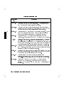
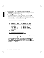
Safety Symbols and Conventions
The following conventions are used throughout this manual:
Note
Caution
Warning
Notes contain important information set o from the text.
Caution messages indicate procedures which, if not observed,
could result in loss of data or damage to equipment. Do not
proceed beyond a CAUTION sign until the indicated conditions
are fully understood and met.
Warning messages indicate procedures or practices which, if
not observed, could result in personal injury. Do not proceed
beyond a WARNING sign until the indicated conditions are fully
understood and met.
Warnings
There is a danger of explosion if the clock battery is incorrectly replaced.
Replace the battery only with the same or equivalent type recommended by
the manufacturer. Discard used batteries according to the manufacturer's
instructions.
(France): Il y a danger d'explosion s'il y a remplacement incorrect de la
batterie. Remplacer uniquement avec une batterie du m^eme type ou d'un
type recommande par de constructeur. Mettre au rebut les batteries usagees
conformement aux instructions du fabricant.
v
Regulatory Information
FCC Statement (For U.S.A. Only)
The Federal Communications Commission (in Subpart J of Part 15, Docket
20780) has specied that the following notice be brought to the attention of the
users of this product:
This equipment has been tested and found to comply with the limits for a
Class A digital device, pursuant to Part 15 of the FCC Rules. These limits
are designed to provide reasonable protection against harmful interference
when the equipment is operated in a commercial environment. This
equipment generates, uses, and can radiate radio frequency energy, and, if
not installed and used in accordance with the instruction manual, may cause
harmful interference to radio communications. Operation of this equipment
in a residential area is likely to cause harmful interference, in which case the
user will be required to correct the interference at his own expense.
70 dB Declaration (Germany Only)
Laermangabe nach der Maschinenlaermverordnung | 3GSGV
(Deutschland)
(Noise Declaration | German Law)
LpA < 70 dB
am Arbeitsplatz (operator's position)
normaler Betreib (normal operation)
nach DIN 45635 T. 19 (per ISO 7779)
vi
VCCI Statement (Japan Only)
vii
x x x x x x x x x x x x Replace this page with the Ventura Decl of Conformity
xxxxxxxx
viii
Printing Conventions
This book uses the following typographical conventions:
If you see . . .
It means . . .
computer text Represents text you will see on the screen or text you must
type/enter yourself. For example,
login:
indicates a login prompt displayed by the system.
italic text
Variable text supplied by you. For example,
le name
means that you type a le name of your choice.
Italic text is also used for text emphasis and for document titles.
4Key5
Type the corresponding key on the keyboard. For example,
4CTRL5-4D5
means you hold down the
NNNNNNNNNNNNNNNNNNNNNNNNNN
Displayed
NNNNNNNNNNNNN
Item
4CTRL5
key, and press the 4D5 key.
Select an on-screen item or a corresponding softkey. For example,
NNNNNNNNNNNNNN
Help
ix
Contents
1. Product Description
Chapter Contents . . . . . . . . . . . . . . . .
The HP 9000 Model V743 Embedded VXI Controller
Features . . . . . . . . . . . . . . . . . . .
Memory Congurations . . . . . . . . . . . .
Interfaces . . . . . . . . . . . . . . . . . .
Graphics . . . . . . . . . . . . . . . . . . .
Operating System . . . . . . . . . . . . . . .
.
.
.
.
.
.
.
.
.
.
.
.
.
.
.
.
.
.
.
.
.
.
.
.
.
.
.
.
.
.
.
.
.
.
.
1-1
1-2
1-2
1-3
1-4
1-5
1-6
2. Finding Information About Your System
Chapter Contents . . . . . . . . . .
Overview . . . . . . . . . . . . .
Manuals for System Information . .
Online Sources of Information . . . .
.
.
.
.
.
.
.
.
.
.
.
.
.
.
.
.
.
.
.
.
.
.
.
.
.
.
.
.
.
.
.
.
.
.
.
.
.
.
.
.
.
.
.
.
2-1
2-2
2-2
2-4
3. Getting Started with HP-UX
Chapter Contents . . . . . . .
Before Logging In the First Time
System Requirements . . . .
Turning On the System . . . .
Conguring the Controller . . .
Conguring the RS-232 Ports . .
Logging In and Out . . . . . .
Logging In . . . . . . . . .
Logging Out . . . . . . . .
Creating a New User Account .
Setting or Changing a Password
Selecting a New Password . .
Powering Down the System . .
Using the Command Line . . .
.
.
.
.
.
.
.
.
.
.
.
.
.
.
.
.
.
.
.
.
.
.
.
.
.
.
.
.
.
.
.
.
.
.
.
.
.
.
.
.
.
.
.
.
.
.
.
.
.
.
.
.
.
.
.
.
.
.
.
.
.
.
.
.
.
.
.
.
.
.
.
.
.
.
.
.
.
.
.
.
.
.
.
.
.
.
.
.
.
.
.
.
.
.
.
.
.
.
.
.
.
.
.
.
.
.
.
.
.
.
.
.
.
.
.
.
.
.
.
.
.
.
.
.
.
.
.
.
.
.
.
.
.
.
.
.
.
.
.
.
.
.
.
.
.
.
.
.
.
.
.
.
.
.
3-1
3-2
3-3
3-6
3-8
3-10
3-11
3-11
3-11
3-12
3-14
3-14
3-15
3-16
.
.
.
.
.
.
.
.
.
.
.
.
.
.
.
.
.
.
.
.
.
.
.
.
.
.
.
.
.
.
.
.
.
.
.
.
.
.
.
.
.
.
Contents-1
4. Conguring for a VXI/MXI System
Chapter Contents . . . . . . . . . . . . . . . . . . .
Overview . . . . . . . . . . . . . . . . . . . . . .
Description of HP SICL . . . . . . . . . . . . . . .
Examining Your VXI/MXI Conguration . . . . . . . .
Default Values . . . . . . . . . . . . . . . . . . .
Changing Your VXI/MXI Conguration . . . . . . . . .
Changing the VXI Shared Memory . . . . . . . . . .
Conguring the VXI/MXI Trigger Lines . . . . . . . . .
Routing VXI TTL Trigger Lines in a VXI/MXI System .
Routing VXI TTL Trigger Lines in a Multiple Mainframe
System . . . . . . . . . . . . . . . . . . . . .
Inverting the Polarity of the V743 External Trigger Lines
Examining the VXI/MXI Boot Process . . . . . . . . .
Viewing the VXIbus System Conguration . . . . . . .
VXI/MXI Conguration les . . . . . . . . . . . . .
The iproc Utility (Initialization and SYSRESET) . . .
Using HP SICL for VXIbus Backplane Communication . .
For More Information . . . . . . . . . . . . . . . .
.
.
.
.
.
.
.
.
.
.
.
.
.
.
.
.
.
.
4-1
4-2
4-2
4-3
4-3
4-4
4-4
4-5
4-7
.
.
.
.
.
.
.
.
.
.
.
.
.
.
.
.
4-7
4-9
4-10
4-11
4-11
4-13
4-15
4-16
5. Conguring Graphics
Chapter Contents . . . . . . . . . . . .
Overview . . . . . . . . . . . . . . .
Identifying Graphics Cards . . . . . . .
Displaying Graphics on a Remote X Host
For More Information . . . . . . . . .
.
.
.
.
.
.
.
.
.
.
.
.
.
.
.
.
.
.
.
.
.
.
.
.
.
.
.
.
.
.
.
.
.
.
.
.
.
.
.
.
.
.
.
.
.
5-1
5-2
5-3
5-3
5-3
6. Conguring HP-UX for Printers
Chapter Contents . . . . . . .
Preparing for Installation . . .
Conguring HP-UX for a Printer
Testing the Printer Installation
Dealing With Printer Problems
.
.
.
.
.
.
.
.
.
.
.
.
.
.
.
.
.
.
.
.
.
.
.
.
.
.
.
.
.
.
.
.
.
.
.
.
.
.
.
.
.
.
.
.
.
6-1
6-2
6-3
6-5
6-6
Contents-2
.
.
.
.
.
.
.
.
.
.
.
.
.
.
.
.
.
.
.
.
.
.
.
.
.
7. Conguring HP-UX for a DDS Tape Drive
Chapter Contents . . . . . . . . . . . . . . .
Finding the Status of Existing SCSI Bus Addresses
Conguring for a Backup DDS Tape Drive . . . .
Conguring the Drive on HP-UX . . . . . . .
Testing Your Installation . . . . . . . . . . .
DDS Tape Drive LED Indicators . . . . . . .
Maximum Usage of DDS Cassettes . . . . . .
In Case of Diculty . . . . . . . . . . . . .
.
.
.
.
.
.
.
.
.
.
.
.
.
.
.
.
.
.
.
.
.
.
.
.
.
.
.
.
.
.
.
.
.
.
.
.
.
.
.
.
.
.
.
.
.
.
.
.
7-1
7-2
7-3
7-4
7-6
7-7
7-8
7-8
8. Backing Up and Restoring Software
Chapter Contents . . . . . . . . . . . . .
Backing Up Your HP-UX System and Software
Creating a Recovery System . . . . . . .
Backing Up Your File Systems . . . . . .
Restoring Individual Files . . . . . . . . .
Restoring HP-UX Using the Recovery Tape .
For More Information . . . . . . . . . .
.
.
.
.
.
.
.
.
.
.
.
.
.
.
.
.
.
.
.
.
.
.
.
.
.
.
.
.
.
.
.
.
.
.
.
.
.
.
.
.
.
.
.
.
.
.
.
.
.
.
.
.
.
.
.
.
8-1
8-2
8-2
8-4
8-7
8-10
8-12
9. Dealing With Problems
Chapter Contents . . . . . . . . . . . . . .
Interpreting the LED Indicators . . . . . . .
Managing a Boot Failure . . . . . . . . . . .
Boot Program Initializes Hardware . . . . .
Selecting an Alternate Operating System . . .
Recovering from a System Panic . . . . . . .
Procedures for Recovering from a System Panic
Dealing with Network Failures . . . . . . . .
.
.
.
.
.
.
.
.
.
.
.
.
.
.
.
.
.
.
.
.
.
.
.
.
.
.
.
.
.
.
.
.
.
.
.
.
.
.
.
.
.
.
.
.
.
.
.
.
.
.
.
.
.
.
.
.
9-1
9-2
9-4
9-4
9-5
9-7
9-9
9-13
A. Installing Additional Memory
Appendix Contents . . . . . .
RAM Upgrade Products . . . .
Planning for Installation of RAM
Determining Existing Memory
Installing the RAM Boards . . .
.
.
.
.
.
.
.
.
.
.
.
.
.
.
.
.
.
.
.
.
.
.
.
.
.
.
.
.
.
.
.
.
.
.
.
A-1
A-2
A-3
A-3
A-4
.
.
.
.
.
.
.
.
.
.
.
.
.
.
.
.
.
.
.
.
.
.
.
.
.
.
.
.
.
.
.
.
.
.
.
Contents-3
B. Using the Boot Console Handler
Appendix Contents . . . . . . . . . . . . . . .
The Boot Console Handler . . . . . . . . . . . .
Special Tasks . . . . . . . . . . . . . . . . .
Boot Console Information Display . . . . . . . .
Using the Boot Console Handler Interface . . . .
Conguring the Console Path and Display Format
Booting and Resetting the VXIbus Mainframe . .
Searching for Bootable Media . . . . . . . . . .
Displaying and Setting Paths . . . . . . . . . .
Displaying and Setting the Secure Boot Mode . .
Displaying the LAN Station Address . . . . . .
Interactive Testing. . . . . . . . . . . . . . .
Displaying Firmware Information. . . . . . . . .
Glossary
Index
Contents-4
.
.
.
.
.
.
.
.
.
.
.
.
.
.
.
.
.
.
.
.
.
.
.
.
.
.
.
.
.
.
.
.
.
.
.
.
.
.
.
.
.
.
.
.
.
.
.
.
.
.
.
.
.
.
.
.
.
.
.
.
.
.
.
.
.
B-1
B-2
B-2
B-2
B-3
B-4
B-9
B-10
B-11
B-15
B-18
B-19
B-21
1
1
Product Description
Chapter Contents
Features.
Memory Congurations.
Interfaces.
Graphics.
Operating System.
Product Description
1-1
1
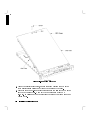
The HP 9000 Model V743 Embedded VXI Controller
The HP 9000 Model V743 VXI controller is an exceptionally exible and
responsive high-performance Precision Architecture VXI controller based on
the Hewlett-Packard PA-RISC 7100LC technology. Some of the features are
outlined in this chapter. See your Installation Guide for detailed hardware
information.
Features
The Model V743 VXI controller has the following general features:
Single-slot VXI C-size conguration.
64-MHz PA-RISC processor (Model V743/64).
100-MHz PA-RISC processor (Model V743/100).
HP-UX 9.05 (minimum) Operating System.
Congurable with 16 MB to 128 MB main memory (see \Memory
Congurations").
For the Model V743/64: factory-installable RAM is 16 MB to 64 MB.
For the Model V743/100: factory-installable RAM is 32 MB to 128 MB.
Error-Checking and Correcting (ECC) SIMM RAM.
External Cache: 256 KB merged (64-MHz or 100-MHz CPU):
Congurable for 1 MB of shared memory.
Total external disk capacity: 14 GB.
Input/Output:
On-Board Graphics.
RS-232C (2 ports).
HP-IB.
Trigger Input-Output.
Clock Input-Output.
AUI (LAN).
Audio interface: 16-bit voice quality; composite mono; audio connector
(one output jack for speaker or headphone).
SCSI-II single ended.
PS/2 Keyboard and Mouse; Mini-DIN Connector.
1-2
Product Description
1
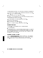
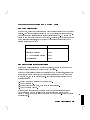
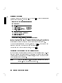
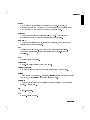
Memory Configurations
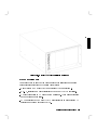
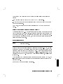
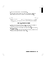
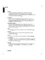
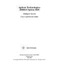
Figure 1-1. Four RAM Cards Installed
The standard Model V743 VXI controller comes with either 16 MB or 32 MB
factory-installed RAM, with other options possible. It can be upgraded by the
user with internal RAM cards as follows (two cards per upgrade):
HP A2578A; 16 MB total.
HP A2829A; 32 MB total.
HP A2827A; 64 MB total.
Upgrades or factory-integrated RAM provide the Model V743 VXI controller
with up to 128 MB maximum memory. See Appendix A for installation
instructions.
Product Description
1-3
1
Interfaces
For graphics, printing, and LAN communications, the Model V743 VXI
controller provides the following I/O interfaces:
Graphics (on-board GSC; integrated color).
640 x 480 (15-in. monitor).
800 x 600 (15-in. monitor).
1024 x 768 (15- or 17-in. monitor).
1280 x 1024 (17- or 20-in. monitor).
1024 x 768 (11.8-in. at panel). (Not currently supported)
LAN AUI (high-density, 15-pin D-subminiature; requires a custom cable and
MAU for connection to LAN).
Two asynchronous RS-232C Interfaces: high-density, 9-pin male DTE (PC
standard). Requires a custom cable.
SCSI-II Interface: high-density, 50-pin; single-ended 8-bit, up to 5 MB/sec.
synchronous.
Custom Cables
The high-density I/O connectors for this board computer require adaptation to
standard cabling, using one or more of the following items (these are provided
with your controller):
HP A4301A
RS-232C: High-density 9-pin to standard 9-pin \M". (2)
HP A4303A
LAN: High-density 15-pin to 15-pin AUI.
HP A4304A
Video: High-density 15-pin to standard 15-pin \F".
HP K2996
SCSI: High-density 50-pin to standard bail lock.
HP 11130A
HPIB: High-density 15-pin to standard 24-pin, IEEE-488.
In addition, standard cables are also available and may be required.
1-4
Product Description
1
Physical Dimensions and Power Requirements
The Model V743 VXI controller occupies one standard VXI slot.
Height: 30.48 mm (1.2 in.)
Width: 259.84 mm (10.23 in.)
Depth: 368.30 mm (14.5 in.)
Power Requirements:
DC Voltage
+5V
+ 12 V
- 12 V
+ 24 V
- 24 V
- 5.2 V
-2V
+5V
STDBY
DC Current
10 A
250 mA
80 mA
40 mA
0 mA
560 mA
480 mA
0 mA
Dynamic Current
100 mA
3 mA
2 mA
1 mA
0 mA
4 mA
2 mA
0 mA
Note that +24V is required only for a at-panel display (not currently
supported).
System power requirements depend to some degree on the RAM conguration as
well as on the software being run. Each additional RAM card adds .2 amps to
the +5 Vdc. requirement at 64 or 100 MHz. See the hardware specications in
your service manual for further information.
Graphics
The Model V743 VXI controller comes with on-board graphics.
For information on currently supported monitors, see Chapter 5 in this
manual, or the current Release Notes le in /etc/newconfig/905RelNotes on
HP-UX 9. For Release Notes on HP-UX 10, see the /usr/share/doc directory.
Product Description
1-5
1
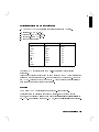
Operating System
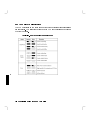
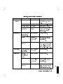
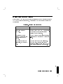
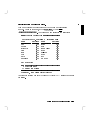
Table 1-1 lists the HP-UX operating system features and languages for the
Model V743 VXI controller.
Table 1-1.
Operating System and Languages
for the Model V743 VXI Controller
Operating system:
HP-UX 9.05 or later
Languages:
HP-PA Assembler 1.1
C and ANSI C
C++
Pascal
ANSI FORTRAN
SICL for C Programming, Revision 3.9
User Interface:
HP-UX 9.05 includes the X Window System and can be
congured with HP VUE 3.0.
Network Features:
IEEE 802.3/Ethernet Local Area Network
ARPA/Berkeley networking services
VXI Backplane Networking (Optional)
TCP/IP
HP Diskless
1-6
Product Description
2
Finding Information About Your System
Chapter Contents
Manuals for System Information:
HP-UX
HP VUE
Online Sources of Information.
Finding Information About Your System
2-1
2
2
Overview
The Model V743 VXI controller uses the standard HP-UX operating
system, a highly versatile system for multitasking, running your application
programs, and performing a variety of development tasks. For information
on installing HP-UX 9, see the manual Installing and Updating HP-UX 9.03
(and the 9.05 Release Notes for updates). For HP-UX 10, see Installing
HP-UX 10 (and the Release Notes in the /usr/share/doc directory for
updates).
To get started with using HP-UX, rst read your Installation Guide , then
go to Chapter 3 in this manual for information on booting and running the
system.
Manuals for System Information
If you have not installed your hardware or started your controller, refer to the
Installation Guide for the Model V743 VXI controller before going on.
HP-UX
After you have done the procedures in the Installation Guide for the Model
V743 VXI controller, you may want to see the following sources for further
information:
For HP-UX administration information, see System Administration Tasks .
For a quick reference to commonly used HP-UX commands, see the
Appendix in Using HP-UX .
HP VUE is the default interface for HP-UX. At some point, you may want to
interact with the Model V743 VXI controller using HP VUE via the LAN,
with an X Window System display. As a simpler window alternative, you
can also use the X Window System by itself. Both are included in HP-UX.
For further information, see the manual Using the X Window System , Using
HP-UX , or HP VUE User's Guide .
The following manuals will also be useful:
If you have not yet installed your HP-UX system, see Installing and
Updating HP-UX 9.03 (and the 9.05 Release Notes in etc/newconfig for
2-2
Finding Information About Your System
updates) for HP-UX 9, or see Installing HP-UX 10 (and the Release Notes
in the usr/share/doc directory) for HP-UX 10.
For troubleshooting HP-UX, see Chapter 9 in this manual, and the manual
Solving HP-UX Problems .
VXI
For VXI conguration information, see the C-Size VXIbus Systems
Conguration Guide . For VXI programming information, see the HP SICL
User's Guide for HP-UX .
HP VUE
For information on using and conguring the HP VUE interface with HP-UX,
see the HP VUE User's Guide . For information on installing HP VUE, see the
HP VUE Installation Guide .
Finding Information About Your System
2-3
2
2
Online Sources of Information
HP-UX is designed so that you can access many sources of information without
leaving your system. Most of these information sources are accessible via the
shell command line on a character terminal.
Man Pages: The information on HP-UX which is found in HP-UX Reference
is also available online. You can access this information by clicking on the up
arrow ( 8 ) over the ? help icon on the HP VUE Front Panel, or by entering
the command line man command , where command is the name of the HP-UX
command or routine you want to get information on. If you're not sure of
the command name, you can enter man -k keyword , where keyword is a
likely topic word to search on. This will result in a display listing commands
having the keyword in their description.
NNNNN
There are also a variety of les on your HP-UX system which contain
version-specic information. These will be useful in administering and
conguring cards and devices for your version of HP-UX. Among these les are
the following:
Release Notes: This is the online version of the Release Notes which came
with your system. It contains all the latest information, undocumented
changes and bug xes for your release of HP-UX. It also contains information
on the current version of HP VUE. The Release Notes document is found
in the /etc/newconfig directory for HP-UX 9, or the /usr/share/doc
directory for HP-UX 10. Look for the le named by its release number, for
example, 905RelNotes, for HP-UX 9.05.
HP-UX and HP VUE Help: For graphics displays, extensive help information
on the operating system and the visual interface is included with HP VUE.
Access it via the ? button on the control panel.
NNNNN
2-4
Finding Information About Your System
Newcong: The directory /etc/newconfig for HP-UX 9, or usr/share/doc
for HP-UX 10, contains information and new versions of HP-UX product
conguration les, as well as shell scripts which may have been customized
on your system. The contents of this directory will vary depending on which
products you have loaded on your system. In most cases, old versions of
these les, in their regular locations in the le system, are not overwritten by
the update process. See the README le in /etc/newconfig on HP-UX 9,
or /usr/share/doc on HP-UX 10, for information on the contents of this
directory.
Finding Information About Your System
2-5
2
3
Getting Started with HP-UX
3
Chapter Contents
Before Logging In the First Time.
Turning On the System.
Conguring the Controller.
Conguring the RS-232 Ports.
Logging In and Out.
Creating a New User Account.
Setting or Changing a Password.
Selecting a New Password.
Powering Down the System.
Using the Command Line.
Getting Started with HP-UX
3-1
Before Logging In the First Time
3
If your Model V743 VXI controller does not have a hard disk connected, or if
it has a le system disk, and you want it to be a cluster client node (cnode),
refer to the manual Managing Clusters of HP 9000 Computers for instructions
on setting up HP-UX clusters and cnodes.
This chapter reviews some initial procedures and provides information on using
both HP VUE sessions and HP-UX. For more detailed information about using
HP VUE after login, see the HP VUE User's Guide .
You should rst read the Installation Guide for the Model V743 VXI controller,
and follow the initial hardware setup and booting procedures applicable to your
conguration. When you rst turn on the VXIbus mainframe to complete the
installation process, your display will ask for information on the time zone,
system host name, and network IP address. If you do not have this information
readily available, simply press 4Enter5 after the questions and you can supply the
information later.
3-2
Getting Started with HP-UX
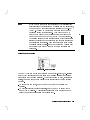
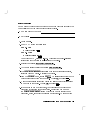
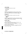
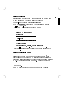
3
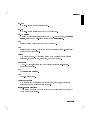
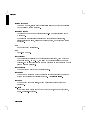
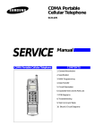
Figure 3-1. Model V743 VXI Controller in Mainframe
System Requirements
You should check to see that you have connected the following components
before proceeding further with booting your system:
Host System: HP Model E1401A or equivalent VXIbus mainframe.
HP-UX, installed on a disk accessible to the Model V743 VXI controller.
A direct connection to AC power for the mainframe. Avoid using extension
power cables or power strips.
LAN connection to the Model V743 VXI controller via an appropriate MAU
interface and custom cable for the AUI.
Getting Started with HP-UX
3-3
3
Custom cables (provided with the Model V743 VXI controller) with
high-density connectors for LAN, monitor, and RS-232C. (See \Custom
Cables" in Chapter 1 for a listing of custom cables.)
Monitor connected to video output, or a terminal or terminal-emulator
system connected to an RS-232C output.
Keyboard connected to the Model V743 VXI controller.
DDS-Format tape drive congured to the SCSI bus of the Model V743 VXI
controller (for backup of local disk, if installed).
Disk congured to the SCSI bus on the Model V743 VXI controller
(optional).
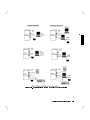
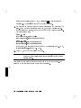
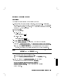
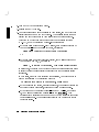
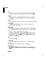
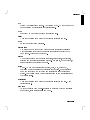
Some of the more common VXIbus congurations with the Model V743 VXI
controller are shown in Figure 3-2.
3-4
Getting Started with HP-UX
3
Figure 3-2. Configurations for the Model V743 VXI Controller
Getting Started with HP-UX
3-5
Turning On the System
Before Booting the System
3
With all peripheral devices turned o, do the following:
1. Install the Model V743 VXI controller according to the instructions in the
Installation Guide for the Model V743 VXI controller.
2. Connect a monitor to your system. See Figure 3-2 for some conguration
alternatives.
3. Turn on the power to the monitor. The power indicator LED on the
monitor will show that it is turned on, even if the screen remains dark.
Make sure of the following:
The appropriate LAN and/or RS-232C connection has been made to the
Model V743 VXI controller.
If you use a remote graphical display host connected via LAN, make sure
the remote system is congured to host the controller. See Figure 3-2 and
\Displaying Graphics on a Remote X Host" in Chapter 5 for the specics
of setting this up.
4. Check SCSI connections.
5. Turn on the power to any peripheral devices, but do not turn on the power
to the VXIbus mainframe until you have read the following note.
3-6
Getting Started with HP-UX
Note
If you want to change the conguration of the controller from
graphics display to displaying on a console (via the serial port),
you can do so by rst connecting the console to the RS-232C
(Port A). (Note: The monitor and keyboard should not be
connected during this procedure.) Then hold the Rst/Abt
switch in the \Abt" (down) position while you cycle power
(turn the power o and back on) on the VXIbus mainframe.
This action starts the boot console routine which interactively
selects the display and congures the computer to recognize a
monitor's format correctly. Prompts for this are given during
the screen display process. See \Conguring the Console Path
and Display Format" in Appendix B for the details of this
procedure.
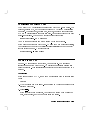
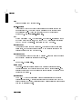
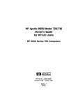
Using the Rst/Abt Switch
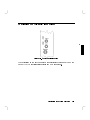
Figure 3-3. Rst/Abt Switch
The Rst/Abt switch on the front panel is a momentary-contact, two-position
switch which enables either a hard reset (in the \Rst" position) or process
termination (in the \Abt" position). The switch is used at boot, as indicated
earlier, to set the computer to display in the correct format for the console
monitor.
To reboot the computer, push the Rst/Abt switch to the \Rst" (up)
position.
To exit all currently running processes, push the Rst/Abt switch to the
\Abt" (down) position. This position is also used when cycling power to
reset the monitor conguration and console path.
Getting Started with HP-UX
3-7
3
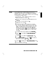
Configuring the Controller
3
A number of congurations are possible, as diagrammed in Figure 3-2. One
common conguration for the controller is as an HP-UX cluster node, or
cnode. See the manual System Administration Tasks for procedures for other
congurations.
Cluster Configuration
After your hardware is in place, you can use SAM on the cluster server to do
most of the conguration tasks. The manual Managing Clusters of HP 9000
Computers gives you detailed guidance for congurations relating to clusters.
The following procedure gives you general guidance for setting up the controller
as a cnode:
1. Ensure that HP-UX has been installed on the server and that it is
appropriately congured as a root server (a cluster that has any Series
700 clients must have a Series 700 root server). Check that a client name
(ARPA host name) has been assigned for the new Model V743 VXI
controller. See Chapter 4 in Managing Clusters of HP 9000 Computers for
more information on this.
2. Log onto the root server as root.
3. Print out a copy of /tmp/cluster.log which contains a list of the
context-dependent les (CSFs) which SAM creates on your system.
4. Get the LAN station address for the new Model V743 VXI controller from
the label on its packing box, or cycle power on its host system and get the
LAN station address from the boot console interface display I/O ASIC
menu. You can also use /etc/lanscan to get this address from a running
system if it already has access to an OS. Write down the LAN station
address.
5. On the cluster server, type the following:
NNNNNNNNNNNNNNNNNNNNNNNNNN
On HP-UX 9:
/usr/bin/sam
4ENTER5
On HP-UX 10:
/usr/sbin/sam
3-8
4ENTER5
Getting Started with HP-UX
6. On HP-UX 10, select Clusters
NNNNNNNNNNNNNNNNNNNNNNNNNN
7. Select NFS Cluster Configuration -->
NNNNNNNNNNNNNNNNNNNNNNNNNNNNNNNNNNNNNNNNNNNNNNNNNNNNNNNNNNNNNNNNNNNNNNNNNNNNNNNNNNNNNNNNN
8. Choose Add Cluster Clients ... on HP-UX 9, or Define Clients on
HP-UX 10.
9. Fill in the information in the selected elds on the SAM form.
10. Click on Add or Apply when the elds are lled in.
NNNNNNNNNNNNNNNNNNNNNNNNNNNNNNNNNNNNNNNNNNNNNNNNNNNNNNNNNNNNNNNNNNNNNNN
NNNNNNNNNNN
NNNNNNNNNNNNNNNNNNNNNNNNNNNNNNNNNNNNNNNNNNNN
NNNNNNNNNNNNNNNNN
11. Enter information for the next cnode to be added, if any.
OR
12. Click on OK to end the process if you have no more cnodes to add, and
wait for conrmation that the action has been completed successfully.
13. Check /tmp/cluster.log for errors.
14. Boot each new client.
15. Use SAM to add local DDS drives, for backup, if needed.
Install your SICL software onto the server disk for each cnode including
rebuilding the kernel after each SICL installation. Use the conguration steps
for SICL in Chapter 4 in this manual. You will nd further information in the
HP SICL User's Guide for HP-UX .
NNNNNNNN
Booting the System
1. If your Model V743 VXI controller is to be a diskless cluster node (cnode),
go to \Conguring the Controller" earlier in this chapter for instructions on
conguring the server.
2. If you have not already done so, turn on the power to the Model V743 VXI
controller by powering up the VXIbus mainframe. The controller turns on
with the host system that it is plugged into.
The topmost green LED (\Boot . . . Run") on the panel will blink slowly
until HP-UX is booted, then it is continuously on. The other green LED
(\Act") will blink when there is VXI backplane access activity. The two red
LEDs (second and fourth) will only light if there is a system problem in this
VXI system. Details of the indications are given in Table 9-1.
Getting Started with HP-UX
3-9
3
3
3. You should see a sequence of boot messages. As shipped, the Model V743
VXI controller will rst attempt to boot from an external SCSI device
at SCSI address 6 if present, then at SCSI address 5 if present, then from
any LAN-congured system for which this system is a valid cluster client.
If there are multiple cluster servers that could recognize this client, or
if you are installing HP-UX from CD-ROM, you should interrupt the
automatic boot selection by pressing the 4ESC5 key, then select key 1
Boot From a Device to select the correct boot device. See Appendix B for
more information about conguring the automatic boot selection.
4. During the boot process, a new system will give you messages prompting
you for the host name, IP number, and time zone. If you have this
information, enter it as requested. Otherwise, press 4Enter5. You can also
enter or update this information later by typing set_parms 4Enter5 after
login. The information is as follows:
a. The time zone where your system is located.
b. The host name for your system - any alphanumeric, single-word name
with eight or fewer characters.
c. The network address number, also called an IP number, for your system.
This consists of four address elds separated by periods: for example,
255.32.3.10 . You may need to consult with your system administrator
for this information. Or, if your host name and IP number have already
been assigned, you can nd out the host name after boot by entering
uname -a. If you know your host name, you can nd out your IP number
by entering nslookup host name at the system prompt.
5. You will also be asked if you want to set a root password at this time. If so,
see \Selecting a New Password" in this chapter for password requirements.
Finally, you will see the \Console login:" prompt.
NNNNNNNNNNNNNNNNNNNNNNNNNNNNNNNNNNNNNNNNNNNNNNNNNNNNNNNN
3-10
Getting Started with HP-UX
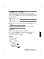
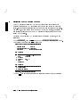
Configuring the RS-232 Ports
The Model V743 VXI controller comes equipped with two RS-232C ports. The
rst port, labeled \A", may be congured using SAM (System Administration
Manager). The second port, labeled \B", however, cannot be congured using
SAM; SAM will incorrectly congure this port. To congure this port you need
super-user privilege. The command for conguring this port is:
mknod /dev/rs232_b c 1 0x702004
You may choose a dierent name than \rs232 b" for the device le.
If you plan to use this port with the HP-UX \cu" command or similar utilities,
you will also need to modify the /usr/lib/uucp/Devices le to add an entry
for this device le name. A typical entry is:
Direct rs232_b - 9600 direct
Logging In and Out
Once HP-UX is running on your system, you must log in. The process of
logging in is one of the ways that HP-UX prevents unauthorized persons from
using your system. This is especially important if your system is attached to a
network.
Logging In
If you are not using HP VUE, then a command line login prompt appears after
boot:
login:
1. Type your login name (or root). (See \Setting or Changing a Password" for
setting a password).
2. Press 4Enter5.
If you haven't yet set a password, you will get a a system prompt (\#" for
root, or $ for user), and you can begin using the system.
Getting Started with HP-UX
3-11
3
3. Otherwise, type your password when the system gives the following prompt:
Password:
4. Press 4Enter5. The system prompt (\#" or \$") appears and you can use the
system.
3
Logging Out
If you are not using HP VUE, you can use the lock command to temporarily
leave your system (while leaving processes running). If you want to log out of
your current work session entirely, use the following command:
exit
3-12
Getting Started with HP-UX
Creating a New User Account
If you have access to a system administrator, that person may have already set
up a user account for you. Otherwise, you will need to do the following to set
up a user account so that you can interact with the system as non-root and
not incur the risk of accidentally damaging data.
You usually work in your home directory or \account", and most of your
default les are kept there. As \owner" of this directory and its subdirectories,
you also have control over access to the les in the account.
Using SAM
To create a user account, you will need to use SAM, the System
Administration Manager.
Caution
In order to use SAM, you must be logged in as root (indicated
by the command prompt \#"). The root account is a separate
login account providing unlimited permissions on your system.
This means that you need to take actions more carefully when
you are root. The root account is only used to do system
administration tasks, and, for security reasons, it should use a
password which is dierent from your everyday user password.
Using HP-UX and System Administration Tasks give you more
details on using SAM.
Getting Started with HP-UX
3-13
3
You can navigate around a SAM screen on a character terminal using the
arrow keys and 4Tab5 to illuminate the selection you want to activate. When the
selection is illuminated, press 4Enter5 to activate (or \choose") it.
1. Type the following:
3
On HP-UX 9:
/usr/bin/sam
4ENTER5
On HP-UX 10:
/usr/sbin/sam
4ENTER5
2. At the opening menu, choose Users and Groups-> by pressing 4Enter5 with
Users and Groups-> illuminated.
NNNNNNNNNNNNNNNNNNNNNNNNNNNNNNNNNNNNNNNNNNNNNNNNNNNNNNNN
NNNNNNNNNNNNNNNNNNNNNNNNNNNNNNNNNNNNNNNNNNNNNNNNNNNNNNNN
3. At the next screen, choose Users . You will see a screen displaying a list of
logins and real names.
4. Go to the Actions menu (use the appropriate function key to get to the
menu bar). Select Add from the Actions pull-down menu. You will see a
form Add a User Account .
NNNNNNNNNNNNNNNNN
NNNNNNNNNNNNNNNNNNNNNNN
NNNNNNNNNNN
NNNNNNNNNNNNNNNNNNNNNNN
NNNNNNNNNNNNNNNNNNNNNNNNNNNNNNNNNNNNNNNNNNNNNNNNNNNNNNNN
5. Fill in your login name, choice of start-up program and environment (if
dierent from the defaults given), and the optional information.
Note
3-14
At this point you can select X Windows as your login default
environment, if you so desire.
Getting Started with HP-UX
NNNNNNNN
6. Choose OK when you are nished.
7. You will be asked to select a password. (See \Selecting a New Password"
for password requirements. If you wish, you can select a temporary
password and reset it later.) Type the password and choose OK (or press
4Enter5). Re-enter the password as requested and choose OK . The re-entered
password must match the rst.
8. Choose OK .
NNNNNNNN
NNNNNNNN
NNNNNNNN
9. When the \Task Completed" message appears, choose OK .
NNNNNNNN
10. Select Exit then Exit SAM .
NNNNNNNNNNNNNN
NNNNNNNNNNNNNNNNNNNNNNNNNN
Getting Started with HP-UX
3-15
3
Setting or Changing a Password
From a command line shell prompt, you can use the passwd command
directly to set or change a password. (You do not have to be root.) Enter the
following:
3
passwd
4Enter5
You will be prompted for your old password. Then you will be prompted to
enter and re-enter your new password. The re-entered password must match
the rst entry.
See the \Selecting a New Password" section below if you need help with
selecting passwords. Use the same procedure to change an old password
as to add a new password. If you already have one, you will be prompted
appropriately for the old password.
Selecting a New Password
If you have already booted and used your system, you should already have set
dierent passwords for your user account and for root.
However, you will also want to change your password from time to time as a
matter of good security practice. The following gives the general requirements
of setting passwords.
A password must meet four criteria to be valid:
Contain at least six characters.
At least two characters must be alphabetic.
At least one character must be a number (0-9) or a special character (/, ?, !,
or other punctuation mark).
Dier from your previous password by at least three characters.
Your password is case sensitive, so the password ?Secret is dierent from the
password ?secret. Your password can also be as long as you want, but only
the rst eight characters are checked.
If you are adding many users to your system, see System Administration Tasks
for the details of controlling access to your system.
If you have not yet set your password, you can do so using SAM or a shell
command line.
3-16
Getting Started with HP-UX
Powering Down the System
Caution
If you have a local disk connected to the Model V743 VXI
controller, do not turn o power to the system without rst
shutting down the controller's operating system software
according to the following procedure. Turning o the power
for your system without rst doing the shutdown procedure
may result in damage to data on your disk. Always execute the
shutdown process to completion rst.
1. Exit all processes currently running.
2. Execute the shutdown command as described in the next section to bring
the system to a halted state.
You can do this either from the command line, with SAM, or by using the
HP VUE Toolbox. The following procedure uses the conventional HP-UX
command.
Using the Shutdown Command to Stop Your System
1. As root, exit your applications and, at a shell prompt, type the following
command:
cd / 4Enter5
shutdown -h 0
4Enter5
This gives a zero-length \grace period" before the system goes down to the
halted state.
2. You will see a message:
Halted, you may now cycle power.
3. At this time the system no longer responds to keyboard input and you may
turn o the power. Turning the system back on again will initiate the boot
sequence (see Appendix B).
If you want to shut down and reboot automatically instead of using the above
procedure, simply enter the shutdown command with no options.
See shutdown (1M) for various other options.
Getting Started with HP-UX
3-17
3
Using the Command Line
For guidance on entering HP-UX commands and using the HP-UX le system,
tools, and networking commands, see the manual Using HP-UX . For more
advanced work with shell programming, see the manual Shells: User's Guide .
3
3-18
Getting Started with HP-UX
4
Configuring for a VXI/MXI System
Chapter Contents
Overview.
Examining Your VXI/MXI Conguration.
Changing Your VXI/MXI Conguration.
Conguring the VXI/MXI Trigger Lines.
Examining the VXI/MXI Boot Process.
Using HP SICL for VXIbus Backplane Communication.
Configuring for a VXI/MXI System
4
4-1
Overview
If your Model V743 VXI controller is to be a node in an HP-UX cluster, and
it has not yet been installed and congured according to the procedures in the
Installation Guide for the Model V743 VXI controller, see \Conguring the
Controller" in Chapter 3 before proceeding.
4
This chapter describes the VXIbus default values and how to change these
values using the utilities provided with the HP Standard Instrument Control
Library (SICL). SICL is an I/O library that comes with your Model V743
VXI controller. You can use SICL for communication with your VXI
SCPI-compatible instruments. Install SICL according to the instructions in the
HP SICL User's Guide for HP-UX . If you have an application other than HP
SICL, see your application's documentation for information on changing the
VXIbus conguration.
Description of HP SICL
SICL is a modular instrument communications library that works with a
variety of computer architectures, I/O interfaces, and operating systems.
Applications written in C or C++ using this library can be ported at the
source code level from one system to another without, or with very few,
changes.
SICL uses standard, commonly used functions to communicate over a wide
variety of interfaces. For example, a program written to communicate with
a particular instrument on a given interface can also communicate with an
equivalent instrument on a dierent type of interface. This is possible because
the commands are independent of the specic communications interface.
SICL also provides commands to take advantage of the unique features of
each type of interface, thus giving the programmer complete control over I/O
communications.
4-2
Configuring for a VXI/MXI System
Examining Your VXI/MXI Configuration
Default Values
Your Model V743 VXI controller comes precongured from the factory as
follows:
VXI Logical Address : 0.
VXI Servant Area Size : 255.
VXI Bus Error Timeout : 1ms.
VXI Shared Memory : 0 (disabled).
4
The above values are programmed into the Model V743 VXI controller
EEPROMs at the factory. There are times, however, when you want to change
these values. See the next section \Changing Your VXI/MXI Conguration,"
for details on changing these values.
Configuring for a VXI/MXI System
4-3
Changing Your VXI/MXI Configuration
SICL includes some Model V743 VXI controller conguration utilities that are
used to change the VXI Shared Memory in the VXIbus conguration.
Changing the VXI Shared Memory
4
You can reserve 1 MByte of the Model V743 VXI controller system memory to
be used as VXI shared memory in A24 address space. The Model V743 VXI
controller is shipped with this feature disabled. When enabled, 1 MByte of the
system memory becomes unavailable for use by HP-UX and your applications.
Instead, this memory is mapped onto the VXI backplane for use as VXI shared
memory. You can use the SICL \e1497cnf" utility to enable or disable this
feature by executing the following:
On HP-UX 9:
/usr/pil/bin/e1497cnf -i vxi
On HP-UX 10:
/opt/sicl/bin/e1497cnf -i vxi
See the \Customizing your VXI/MXI System" chapter in the HP SICL User's
Guide for HP-UX for more information on using the e1497cnf utility.
Note
4-4
You must be super user in order to run this utility. This utility
also requires you to reboot the system.
Configuring for a VXI/MXI System
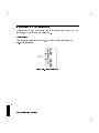
Configuring the VXI/MXI Trigger Lines
4
Figure 4-1. Front Panel Trigger I/O
The table listed on the next page shows the relationship between SICL and the
Model V743 VXI controller trigger lines and SMB connectors.
Configuring for a VXI/MXI System
4-5
Trigger Lines
4
4-6
SICL
V743
I TRIG TTL0
TTL0
I TRIG TTL1
TTL1
I TRIG TTL2
TTL2
I TRIG TTL3
TTL3
I TRIG TTL4
TTL4
I TRIG TTL5
TTL5
I TRIG TTL6
TTL6
I TRIG TTL7
TTL7
I TRIG ECL0
ECL0
I TRIG ECL1
ECL1
I TRIG ECL2
INVALID
I TRIG ECL3
INVALID
I TRIG EXT0
Trig in
I TRIG EXT1
Trig out
I TRIG EXT2
INVALID
I TRIG EXT3
INVALID
I TRIG CLK0
16 MHz Clock
I TRIG CLK1
INVALID
I TRIG CLK2
INVALID
I TRIG CLK10
INVALID
I TRIG CLK100
INVALID
Configuring for a VXI/MXI System
Routing VXI TTL Trigger Lines in a VXI/MXI System
Use the SICL ivxitrigroute function to route VXI trigger lines. For example,
if you want to route TTL7 to Trig out, you can use the following SICL function
call in your program:
ivxitrigroute (id, I_TRIG_TTL7, I_TRIG_EXT1);
See the HP SICL Reference Manual for more information on this and other
SICL functions.
Routing VXI TTL Trigger Lines in a Multiple Mainframe System
When you have multiple mainframes connected via the MXIbus, the TTL
trigger lines are not routed from one mainframe to another. The INTXbus does
not allow multiple INTXbus devices to drive the same TTL trigger line. If
you need TTL trigger lines in the extended VXI mainframes, you need to edit
the /usr/pil/etc/vxi16/ttltrig.cf conguration le on HP-UX 9, or the
/etc/opt/sicl/vxi16/ttltrig.cf conguration le on HP-UX 10, to map
the TTL trigger line to the source logical address.
The following example illustrates an entry in the ttltrig.cf le, where the
rst column is the TTL trigger line and the second column is the logical
address of the TTL trigger source:
0
1
2
3
4
5
6
7
0
0
0
0
0
0
0
0
(Multiple trigger sources are still allowed on the same line within the same
mainframe.)
In the example above, all TTL trigger lines are sourced by the device at logical
address 0.
The following is an example of what you would see when the resource manager
runs:
Configuring for a VXI/MXI System
4-7
4
VXI-MXI TTL Trigger Routing:
Name
0 1 2 3 4 5 6 7
---- - - - - - - hpvximxi
I I I I I I I I
I - MXI->VXI
O - VXI->MXI
* - Not Routed
Now the following illustrates TTL trigger line 1 being sourced by the device at
logical address 24:
4
ttltrig.cf le:
0
1
2
3
4
5
6
7
0
24
0
0
0
0
0
0
resource manager output:
VXI-MXI TTL Trigger Routing:
Name
0 1 2 3 4 5 6 7
---- - - - - - - hpvximxi
I 0 I I I I I I
I - MXI->VXI
O - VXI->MXI
* - Not Routed
4-8
Configuring for a VXI/MXI System
Note
You can use the /usr/pil/bin/e1489trg diagnostic test on
HP-UX 9, or /opt/sicl/bin/e1489trg test on HP-UX 10, for
the MXI/INTX trigger and interrupt circuitry. See Appendix
F, \Conguring your VXI/MXI System," in the HP SICL
User's Guide for HP-UX for information on this and other
diagnostic tests for the E1489 MXIbus Controller Interface.
Inverting the Polarity of the Model V743 VXI Controller External
Trigger Lines
At times you may wish to change the polarity of the Trig In and Trig Out
lines on the Model V743 VXI controller. This would allow you to connect to
an external device independent of the device's polarity. There is a SICL utility,
itrginvrt, that can be used to do just this. The following is an example that
inverts the polarity of the Trig In line:
itrginvrt -a vxi -i ON -o OFF
Where:
-a vxi species the interface name, vxi
-i ON species that the Trig In line is to be inverted
-o OFF species that the Trig Out line is not to be inverted
See the \Customizing your VXI/MXI System" chapter in the HP SICL User's
Guide for HP-UX for a complete description of the itrginvrt utility.
Note
The external trigger lines remain inverted until power is cycled
or the resource manager runs (with iclear or ivxirm, for
example). The external trigger lines then return to the same
state as the trigger line routed to them.
Configuring for a VXI/MXI System
4-9
4
Examining the VXI/MXI Boot Process
4
When HP SICL is installed and congured according to the procedures in the
HP SICL User's Guide for HP-UX , certain SICL utilities are copied onto
your system. These utilities automatically run when the system boots. The
following is a summary of the VXIbus boot process utilities:
iproc
This utility runs at system boot and performs various system
initialization functions. It uses the iproc.cf conguration le to
determine when the other conguration utility runs.
ivxirm
This utility runs the resource manager which initializes and
congures the VXI/MXI mainframe resources. The resource
manager reads the VXI/MXI conguration les and polls the
VXI devices to determine their resources and capabilities.
This utility runs at mainframe initialization if specied in the
iproc.cf conguration le (the default is to not run at mainframe
initialization).
Note
4-10
These utilities and conguration les are only provided with
the SICL VXI leset. In order to use VXI/MXI, you must
have loaded this leset during the SICL installation. See the
HP SICL User's Guide for HP-UX for SICL installation and
conguration information.
Configuring for a VXI/MXI System
Viewing the VXIbus System Configuration
You can use the SICL ivxisc utility to read the current system conguration
and print a human readable display:
On HP-UX 9:
ivxisc /usr/pil/etc/vxi16
On HP-UX 10:
ivxisc /etc/opt/sicl/vxi16
See \The HP SICL Utilities" chapter of the HP SICL User's Guide for HP-UX
for information on using this utility.
Note
The boot-up initialization line is commented out by
default. You must un-comment the following line in
the /usr/pil/etc/iproc.cf le on HP-UX 9, or the
/etc/opt/sicl/iproc.cf le on HP-UX 10, in order for the
resource manager to run on boot-up.
boot ivxirm -p I vxi
VXI/MXI Configuration Files
The VXI/MXI conguration les are used to specify some site-dependent
conguration rules and any changes from the default. These les are not
usually edited except under special circumstances. See the HP SICL User's
Guide for HP-UX for more details on these les and when you want to make
changes to them.
Configuring for a VXI/MXI System
4-11
4
VXI/MXI Configuration Files
Conguration
File
Description
vximanuf.cf Contains a database that cross references the VXI manufacturer id
numbers and the name of the manufacturer. Edit this le if you add a
new VXI vendor that is not currently in the le.
vximodel.cf Contains a database that lists a cross reference of manufacturer id,
model id, and VXI device names. Edit this le if you add a new VXI
device to your system that is not currently in this database.
4
dynamic.cf
Contains a list of VXI devices to be dynamically congured. You only
need to add entries to this le if you want to override the default
dynamic conguration assignment by the resource manager.
vmedev.cf
Contains a list of VME devices that use resources in the VXI
mainframe. Edit this le if you add a VME device to your VXI system.
irq.cf
Contains a database that maps specic interrupt lines to VXI interrupt
handlers. If you have non-programmable interrupters and you want
the interrupters to be recognized by a VXI interrupt handler, you must
make an entry in this le. Keep in mind that not all VXI devices need
to use interrupt lines and not all interrupt lines need to be assigned.
cmdrsrvt.cf Contains a commander/servant hierarchy other than the default for
the VXI system. Edit this le only if you want to override the default
according to the commander's switch settings.
names.cf
Contains a database of a list of symbolic names to assign VXI devices
that have been congured. Edit this le if you add a new VXI device
to your system that is not currently in the database.
oride.cf
Contains values to be written to logical address space for
register-based instruments. This can be used for custom conguration
of register-based instruments every time the resource manager runs.
ttltrig.cf
Contains the mapping of VXI devices to TTL trigger lines for
extended VXI/MXI systems. Edit this le only if you have an
extended VXI/MXI system and you want your TTL trigger lines to be
recognized.
4-12
Configuring for a VXI/MXI System
The
iproc
Utility (Initialization and SYSRESET)
The iproc program is run from /etc/rc. This program becomes a daemon
and monitors the VXI backplane for SYSRESET. The iproc.cf le tells iproc
what to do if a SYSRESET occurs. Usually you want the resource manager
to run and congure your system (since the SYSRESET has destroyed the
conguration).
Note
The SYSRESET line is commented out by default. You must
un-comment the following line in the /usr/pil/etc/iproc.cf
le on HP-UX 9, or the /etc/opt/sicl/iproc.cf le on
HP-UX 10, in order for the resource manager to run on
SYSRESET.
sysreset vxi ivxirm -t 5&
Configuring for a VXI/MXI System
4-13
4
d
The following is an example of the/usr/pil/etc/iproc.cf le:
#
# iproc configuration file
#
a
#
# Boot up functions
#
# Lines are of the form:
#
boot <command_to_execute>
#
boot echo "PIL: Instrument I/O Initialization"
4
# The next line must always exist.
boot pilsetup
#
# V/382 or VXI/MXI Support
#
boot ivxirm -p -I vxi
# When a SYSRESET occurs, rerun the resource manager (delay 5 sec).
# The resource manager MUST be run in the background (i.e. last
# character should be a '&').
sysreset vxi ivxirm -t &
# Sample lines for a second VXI/MXI interface:
#boot ivxirm -p -I vxi2
#sysreset vxi2 ivxirm -t &
c
# The following line must be present for ALL VXI/MXI systems
monitor
4-14
Configuring for a VXI/MXI System
b
Using HP SICL for VXIbus Backplane Communication
Once your VXIbus system is congured, you can start programming with
SICL. SICL allows you to communicate directly over the VXIbus backplane to
SCPI compatible message-based and register-based instruments.
With the SICL C library, you simply open a communications session with the
desired instrument or interface (vxi, or iscpi for register-based instruments)
and send your instrument SCPI (Standard Commands for Programmable
Instruments) commands directly over the VXIbus backplane. The following is a
C language example that queries a VXI instrument for its identication string
and prints the results:
Configuring for a VXI/MXI System
4-15
4
d
/* idn.c
The following program uses SICL to query a VXI
instrument for an identification string and prints the results. */
#include <stdio.h>
#include <sicl.h>
/* SICL header file */
a
/* Modify this line to reflect the address of your device */
#define DEVICE_ADDRESS "vxi,24"
void main()
{
/* declare a device session id */
INST id;
char buf[256];
4
/* error handler to exit if an error is detected */
ionerror(I_ERROR_EXIT);
/* open a device session with device at DEVICE_ADDRESS */
id = iopen (DEVICE_ADDRESS);
/* set timeout value to 1 sec */
itimeout (id, 1000);
/* send a SCPI *RST command and prompt for identification string */
iprintf (id, "*RST\n");
ipromptf (id, "*IDN?\n", "%t", buf);
/* print contents of buf */
printf ("%s\n", buf);
c
}
/* close device session */
iclose (id);
For More Information
See the HP SICL User's Guide for HP-UX and the HP SICL Reference Manual
for information on using HP SICL.
4-16
Configuring for a VXI/MXI System
b
5
Configuring Graphics
Chapter Contents
Monitor Selection.
Displaying Graphics on a Remote X Host.
5
Configuring Graphics
5-1
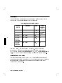
Overview
Graphics operation will require a graphics display monitor connected to the
Model V743 VXI controller selected from the following:
Table 5-1. Supported Color Monitors
Product
Number
5
Resolution
Size
Refresh
Frequency
(Hz)
HP D2806A
1024 x 768
15 in.
70
HP A4032A
1280 x 1024
17 in.
(MultiSync)
HP A4033A
1280 x 1024
20 in.
72
HP A4032B
(Southern
Hemisphere)
1280 x 1024
17 in.
60
HP A4033B
(Southern
Hemisphere)
1280 x 1024
19 in.
72
From time to time, this information may change. For the most recent
information on supported monitors, please see the Release Notes for your
HP-UX system (online in /etc/newconfig on HP-UX 9, or usr/share/doc on
HP-UX 10) or the Support Matrix available from your HP support engineer.
Configuring for a New Monitor
Note that conguration of the Model V743 VXI controller to recognize new
monitors is accomplished interactively by the boot console handler by following
the procedure in \Conguring the Console Path and Display Format" in
Appendix B in this manual.
5-2
Configuring Graphics
Identifying Graphics Cards
NNNNNNNNNNNNNNNNNNNNNNNNNNNNNNNN
Since only on-board graphics is supported on this computer, only GRAPHICS 1
will be indicated in the boot ROM console search display (see Appendix B).
Displaying Graphics on a Remote X Host
You can display graphics using a remote computer with X server capability
connected to the Model V743 VXI controller via LAN. This is done by setting
the DISPLAY environment variable on the controller. DISPLAY sets the host,
display number, and screen number to which a system sends bitmapped output
for clients.
For example, if the Model V743 VXI controller is called server system , your
remote system is xhost system , and the program running on the Model V743
VXI controller is called xwijit, enter the following on the command line of
your remote X host system to get it to display for the server system :
xhost +server system
This enables the Model V743 VXI controller to
recognize the remote X host.
rlogin server system
Log in on the Model V743 VXI controller.
DISPLAY=xhost system:0.0 On the controller, set the DISPLAY variable so
that it will display on your remote X system.
export DISPLAY
Export the variable.
xwijit
Run the program on the Model V743 VXI
controller.
For More Information
For detailed information on running HP VUE in a networked environment, see
the HP VUE User's Guide .
For additional information on conguration for graphics formats, see
\Conguring the Console Path and Display Format" in Appendix B in this
manual.
Configuring Graphics
5-3
5
6
Configuring HP-UX for Printers
Chapter Contents
Preparing for Installation.
Testing the Printer Installation.
Dealing With Printer Problems.
6
Configuring HP-UX for Printers
6-1
Preparing for Installation
You may have to do some conguration for appropriate data interchange with a
new printer. This chapter gives you general guidance for these tasks.
You can use SAM (System Administration Manager) procedures to make
your printer installation easier. SAM can determine the status of any of your
connected devices and will perform the necessary software installation of the
printer for you.
If you don't want to use SAM to install the printer, or if SAM is not on your
system, you can also use HP-UX commands directly to accomplish the same
tasks. For information on using manual system administration procedures for
this, see the manual System Administration Tasks .
6
6-2
Configuring HP-UX for Printers
Configuring HP-UX for a Printer
You will need to supply certain items of information needed to identify the
printer you are installing. It will help you to write down this information now,
so that you have it available to refer to during the software installation process:
Printer Interface:
Serial (RS-232C) (Port A):
Serial (RS-232C) (Port B):
Printer Name (a name the system uses to identify the printer. It can be any
name.):
Printer Model Number (located on a label on the back of the printer):
Printer Cables
For serial data exchange, you will need the following:
HP A4301A (Serial): 9-pin high density to standard 9-pin \M". (Two of
these cables are provided with the Model V743 VXI controller.)
6
Other standard cables may be required.
Procedure:
To install your printer:
1. Log in as root.
2. Run SAM by typing:
On HP-UX 9:
/usr/bin/sam
4Enter5
On HP-UX 10:
/usr/sbin/sam
4ENTER5
Configuring HP-UX for Printers
6-3
To get help in SAM, press the 4f15 key. This key gives you context-sensitive
information for the object at the location of the cursor in either graphical
or character mode.
Use the arrow keys and 4Tab5 to move the highlighted areas around the
screen. Press 4Enter5 to \choose" an item when illuminated (such as OK ).
NNNNNNNN
3. At the SAM opening screen, choose Printers and Plotters .
NNNNNNNNNNNNNNNNNNNNNNNNNNNNNNNNNNNNNNNNNNNNNNNNNNNNNNNNNNNNNNNNN
4. Select Printers/Plotters on the next screen.
NNNNNNNNNNNNNNNNNNNNNNNNNNNNNNNNNNNNNNNNNNNNNNNNNNNNN
If your system doesn't have any printers connected, you will see a message.
Make sure you have a printer connected. Choose OK or press 4Enter5.
NNNNNNNN
5. From the Actions menu (on the menu bar at the top of the screen),
choose Add Local Printer/Plotter .
NNNNNNNNNNNNNNNNNNNNNNN
NNNNNNNNNNNNNNNNNNNNNNNNNNNNNNNNNNNNNNNNNNNNNNNNNNNNNNNNNNNNNNNNNNNNNNNNNNNNN
6. Choose an appropriate selection on the sub-menu giving options for Serial,
HP-IB, etc.
7. A screen will give you information on available serial or parallel interfaces.
8. On HP-UX 9, if you choose Add Serial (RS-232C) Printer/Plotter ,
more than one serial interface could be listed. The serial interfaces are
listed in ascending order. The lowest-numbered serial interface corresponds
to the lowest-numbered serial connector on your system. Choose the one to
which you have connected your printer.
9. Choose OK .
NNNNNNNNNNNNNNNNNNNNNNNNNNNNNNNNNNNNNNNNNNNNNNNNNNNNNNNNNNNNNNNNNNNNNNNNNNNNNNNNNNNNNNNNNNNNNNNNNNNNNNNNNNNNN
6
NNNNNNNN
NNNNNNNNNNNNNNNNNNNNNNNNNNNNNNNNNNNNNNNNNNNNNNNNNNNNNNNNNNNNNNNNNNNNNNNNNNNNN
A display opens for Add Local Printer/Plotter .
10. Choose the box labeled Printer Name and enter your printername for the
new printer (entered in the blank earlier).
11. Select Printer Interface and choose Printer/Model Interface .
NNNNNNNNNNNNNNNNNNNNNNNNNNNNNNNNNNNNNN
NNNNNNNNNNNNNNNNNNNNNNNNNNNNNNNNNNNNNNNNNNNNNNNNNNNNN
NNNNNNNNNNNNNNNNNNNNNNNNNNNNNNNNNNNNNNNNNNNNNNNNNNNNNNNNNNNNNNNNNNNNNNN
12. Scroll down the next screen, using the arrow keys, to nd the Model Name
of your printer.
13. Choose the Model Name (press 4Enter5 when illuminated).
14. Choose OK .
NNNNNNNN
6-4
Configuring HP-UX for Printers
15. In the Add Local Printer/Plotter display which reappears, select and
choose the box labeled Make this the system default printer .
NNNNNNNNNNNNNNNNNNNNNNNNNNNNNNNNNNNNNNNNNNNNNNNNNNNNNNNNNNNNNNNNNNNNNNNNNNNNN
NNNNNNNNNNNNNNNNNNNNNNNNNNNNNNNNNNNNNNNNNNNNNNNNNNNNNNNNNNNNNNNNNNNNNNNNNNNNNNNNNNNNNNNNNNNNNNNNNNNNNNNNNNNNN
16. Choose OK .
NNNNNNNN
17. If the print spooler was not previously running, a screen will appear with
the question: Do you want to start the print spooler now? . Choose
Yes or press 4Enter5.
NNNNNNNNNNNNNNNNNNNNNNNNNNNNNNNNNNNNNNNNNNNNNNNNNNNNNNNNNNNNNNNNNNNNNNNNNNNNNNNNNNNNNNNNNNNNNNNNNNNNNNNNNNNNNNNNNNNNNNNNNNNNNNNNNN
NNNNNNNNNNN
18. You will see a conrmation screen asking if your printer is turned on,
connected to your system, and online. Check your printer to ensure that it
is ready, and press 4Enter5.
19. You will see the message Task completed . Press 4Enter5.
NNNNNNNNNNNNNNNNNNNNNNNNNNNNNNNNNNNNNNNNNNNN
20. Exit the task and press the Exit SAM function key.
NNNNNNNNNNNNNNNNNNNNNNNNNN
21. Type exit 4Enter5 to exit root and return to user status.
Refer to System Administration Tasks for additional SAM information.
Testing the Printer Installation
6
If you made your printer the default system printer, type the following
commands to test it:
cd
4Enter5
lp .profile
4Enter5
(If your printer (called printername ) isn't the default system printer, enter the
following command to test it:)
lp -dprintername .profile
4Enter5
The le named .profile should print out on the new printer.
Configuring HP-UX for Printers
6-5
Dealing with Printer Problems
If you experience problems in printing, check the following:
The power cord for the printer is plugged in.
The printer is turned on.
The printer selection switches are set for online.
Paper is loaded into the printer (and it isn't jammed).
The correct interface has been set up.
The printer cable is connected to the correct interface port on your printer.
The cable is connected to the correct port on your system.
6
6-6
Configuring HP-UX for Printers
7
Configuring HP-UX for a DDS Tape Drive
Chapter Contents
Finding the Status of Existing SCSI Bus Addresses.
Conguring for a Backup DDS Tape Drive.
Conguring the Drive on HP-UX.
Testing Your Installation.
DDS Tape Drive LED Indicators.
Maximum Usage of DDS Cassettes.
In Case of Diculty.
7
Configuring HP-UX for a DDS Tape Drive
7-1
Finding the Status of Existing SCSI Bus Addresses
Before you attach a new SCSI drive, you can use the ioscan tool to help
determine which device addresses are currently in use. To determine the
connected SCSI bus IDs, enter ioscan -fb.
The result will be a display of information, such as the following:
Class
H/W Path Driver
H/W Status
S/W Status
Description
=========================================================================
...
disk
2.0.1.2.0 scsi
ok(0x5800101) ok
tape_drive 2.0.1.3.0 scsitape ok(0x1800202) ok
disk
2.0.1.6.0 scsi
ok(0x101)
ok
TOSHIBA CD-ROM
HP
HP35450A
MICROP 1528
...
For example, the SCSI bus address for the HP 35450A tape device is in the
fourth column of its hardware address as \3" (2.0.1.3 .0). The following
procedure outlines how to use SAM for installing a tape drive.
7
7-2
Configuring HP-UX for a DDS Tape Drive
Configuring for a Backup DDS Tape Drive
You will need to use a backup device if you have local disks connected to the
Model V743 VXI controller. This section contains instructions for conguring
an external DDS drive on HP-UX to use for backup.
Tape Selection
The DDS (\Digital Data Storage") tape drive is a sequential-access, read-write
device using removable DDS cassettes. Although DDS drives are similar
to DAT players in the audio industry, DDS and DAT cassettes are not
interchangeable. There are two major dierences:
1. Audio cassette tapes transfer data in streaming mode, that is, they are
left in motion for periods of minutes. Tapes used for data are continually
starting, stopping and repositioning, which is stressful to the tape. DDS
tapes are made rugged enough to withstand this kind of treatment. Audio
tapes are not expected to perform this well, and as a result they fail very
quickly in a data environment.
2. DDS cassettes have a much tighter case-dimension specication than DAT
cassettes. As a result, DAT cassettes can get stuck in a DDS drive, requiring
the drive to be disassembled. For this reason, only Hewlett-Packard
supported or properly certied DDS tape cartridges should be used. Use of
DAT tapes intended for audio use could void your warranty.
Caution
Do not attempt to extricate a DAT cassette which is stuck
in a DDS drive. You may damage the drive. Have the drive
disassembled by someone qualied to do so.
Configuring HP-UX for a DDS Tape Drive
7
7-3
The general steps for adding a DDS tape drive to your system are as follows:
1. Make sure that the necessary device drivers are congured into the kernel.
On HP-UX, SAM will make this test.
2. Shut your system down and turn o the power.
3. Choose a SCSI bus address for the new tape drive that does not match the
bus address for any other SCSI device.
4. Make all necessary hardware connections for the device.
5. Turn the new tape drive on .
6. Turn your system on and boot HP-UX.
7. Run SAM to create the device le for the new tape drive.
Factory-Set SCSI Address
The factory-set SCSI address for the DDS drive is as follows:
SCSI bus address: 3
As it is possible that the SCSI bus address jumpers for a drive may be shipped
with dierent settings, please check the settings before installing the device.
See the Installation Guide for the device for information on resetting the bus
address, should this be necessary.
Configuring the Drive on HP-UX
NNNNNNNNNNNNNNNNNNNNNNNNNNNNNNNNNNNNNNNNNNNNNNNNNNNNNNNNNNNNNN
7
The SAM Kernel Configuration procedure will conrm which drivers are
active for your tape devices and will congure them as needed for connected
devices. Reconguring the kernel will involve rebooting your system.
7-4
Configuring HP-UX for a DDS Tape Drive
Before You Begin:
Make a note of the tape drive product number and its hardware address (SCSI
bus address) so that you will be able to identify it later.
DDS Drive Product Number:
Bus Address:
1. Log in as root.
2. Run SAM by typing the following:
On HP-UX 9:
$ /usr/bin/sam
4Enter5
On HP-UX 10:
$ /usr/sbin/sam
4ENTER5
To get help in SAM, press the 4f15 key. This gives you context-sensitive
information for the object at the location of the cursor.
3. Highlight and select Peripheral Devices -> .
NNNNNNNNNNNNNNNNNNNNNNNNNNNNNNNNNNNNNNNNNNNNNNNNNNNNNNNNNNNNNNNNN
4. At the next screen highlight and select Tape Drives -> .
NNNNNNNNNNNNNNNNNNNNNNNNNNNNNNNNNNNNNNNNNNNN
5. The Tape Drive Manager screen lists what tape devices are connected,
including your new device. Highlight that device.
6. From the Actions menu, choose Add... . A message screen gives you the
hardware steps for adding the tape drive. Choose OK or press 4Enter5.
NNNNNNNNNNNNNNNNNNNNNNNNNNNNNNNNNNNNNNNNNNNNNNNNNNNNNNNN
NNNNNNNNNNNNNNNNNNNNNNN
NNNNNNNNNNNNNNNNNNNN
NNNNNNNN
7. A conrmation screen indicates whether any related device drivers needed
to be added to the kernel. Choose Yes or press 4Enter5.
NNNNNNNNNNN
8. If you needed to add a device driver, you will also need to create a new
kernel and (eventually) reboot the system. Select from the menu on
the Create a New Kernel screen whether you want to create the new
kernel now, later, or cancel the proposed modications. (Make sure your
NNNNNNNNNNNNNNNNNNNNNNNNNNNNNNNNNNNNNNNNNNNNNNNNNNNNNNNNNNN
Configuring HP-UX for a DDS Tape Drive
7-5
7
choice has an asterisk placed by it, by pressing 4Enter5 while that line is
highlighted.) Choose OK to conrm your choice of action.
NNNNNNNN
9. You will next be given a choice of whether to install the new kernel now or
later. If you move the kernel into place now, the system will also reboot.
If you choose to do it later, you can then move the new kernel and reboot.
You should also move:
On HP-UX 9:
/etc/conf/dfile.sam to /hp-ux
/etc/conf/dfile.sam to /etc/conf/dfile
On HP-UX 10:
/stand/system.sam to /stand/vmunix
/stand/system.sam to /stand/system
If you reboot, the old kernel will be backed up as /SYSBCKUP on HP-UX 9,
or /stand/system.prev on HP-UX 10.
10. Exit SAM, if you have not already done so.
Note
If you are modifying a cluster client's kernel, its kernel is not
backed up, since /SYSBCKUP is used exclusively for the cluster
server's kernel.
Your system is now running the added driver for SCSI DDS tape drive. You
are ready to use the drive to load a tape into your system.
7
7-6
Configuring HP-UX for a DDS Tape Drive
Testing Your Installation
Note that a write-protect tab on the cassette allows you to protect data from
being overwritten. You will need to make sure that the tab is moved to the
\writable" position in order for it to serve as a backup medium.
A simple test to make certain that everything has been installed satisfactorily
is to load a tape in the drive, wait for the \busy" light to stop blinking, and
execute the ioscan command.
The LED on the drive should icker briey. If the command completes
successfully, a listing of your devices, including the tape hardware address,
name and status will be displayed, indicating that it is installed correctly. Note
that the command may fail with a busy error if the command is executed
before the tape has completed loading.
7
Configuring HP-UX for a DDS Tape Drive
7-7
DDS Tape Drive LED Indicators
Two LED indicators on the front panel of the drive indicate several operational
and test states. The following table shows the LED combinations and explains
what they indicate.
Table 7-1. DDS Tape Drive LED State Codes
7
7-8
Configuring HP-UX for a DDS Tape Drive
7
Configuring HP-UX for a DDS Tape Drive
7-9
Caution Indicator
The DDS drive continually monitors the number of errors it has to correct
when reading or writing a tape. This information is presented to the user
through the Caution Indicator (see chart above).
A caution indication has two common meanings:
The tape heads need cleaning.
The tape itself is approaching the end of its useful life.
Maximum Usage of DDS Cassettes
Under optimal environmental conditions (50% relative humidity, 72F),
Hewlett-Packard DDS cassettes are currently specied to 2000 passes over
any part of the tape. In operational terms, this can be translated into
approximately 200 to 300 backup operations. This takes into account that
during a backup, an area of tape may have several passes because streaming
cannot be maintained, or because the backup software requires that certain
areas of the tape are accessed frequently.
Under certain conditions the recommended number of backup operations needs
to be reduced. These conditions are as follows:
Sustained use at low humidity.
Backup software requiring certain areas of the tape being accessed frequently.
7
As a guideline, HP recommends that the number of backup operations should
be limited to 100 per cassette in extreme cases of the above conditions.
In Case of Difficulty
If you experience any problems with the operation of the new drive, contact
your Hewlett-Packard Service Representative for assistance.
7-10
Configuring HP-UX for a DDS Tape Drive
8
Backing Up and Restoring Software
Chapter Contents
Backing Up Your HP-UX System and Software.
Restoring Individual Files.
Restoring HP-UX Using the Recovery Tape.
8
Backing Up and Restoring Software
8-1
Backing Up Your HP-UX System and Software
The most important part of your system is the data you have accumulated. It
is also especially important to protect your system from corruption. You can
protect your data and system from loss, using the general procedures given in
this chapter. (For detailed procedures, see the manual System Administration
Tasks .)
Make sure you create and maintain a backup HP-UX kernel (/SYSBCKUP on
HP-UX 9, or /stand/system.prev on HP-UX 10) on your disk from which
you can boot in an emergency. The backup kernel is automatically created
by SAM whenever you recongure and reboot a new kernel from your system
console.
To build your recovery system, you can use the following devices:
Cartridge tape drives
DDS (\DAT") drives
Magneto-optical disk drives
Other hard disk drives
Back up your le system.
Restore your le system, if needed.
Creating a Recovery System
A \recovery system" is a special tape containing a subset of the HP-UX
operating system. In the event of an operating system failure that prevents you
from booting or logging into HP-UX, you can boot from the recovery system
tape and use the tools on the tape to repair the le system on your disk. A
recovery system is created by using commands rather than by using SAM.
You can also restore your system from a system CD-ROM that you can
purchase from your HP Sales Representative.
8
8-2
Backing Up and Restoring Software
You should make a recovery tape by using the utility mkrs at the following
times:
Immediately after you set up the Model V743 VXI controller.
Each time you update your operating system or make a change in your disk
swap conguration.
To do this, you will need a tape drive (cartridge or DDS) and one or more
tapes.
Using
mkrs
to Create a Recovery System on HP-UX 9
The mkrs utility on HP-UX 9 constructs a recovery system on removable media
(or on a formatted hard disk drive). If a system later becomes unbootable due
to a corrupt root disk, then you can boot your system from the recovery tape.
Once booted on the recovery system, you can then use the tools it provides to
repair the corrupt root disk.
Some Options for
Note
mkrs
The -s option is necessary for building Series 700 DDS tape
recovery systems.
If enough free disk space is available in /usr/tmp (typically 10-20 MB), the -q
option can be used to make mkrs create an image of the recovery system in this
directory before copying it to the recovery media. This option generally saves a
great deal of time due to reduced seeking on non-random-access recovery media
(cartridge tape and DDS). Note: for DDS tape recovery systems, the -q option
is assumed.
When creating a DDS recovery system for a small memory system (8 MB), the
-s option should be used to specify that a smaller set of les be placed on the
recovery system.
See mkrs (1M) for more options with mkrs.
Backing Up and Restoring Software
8-3
8
Source Device Files
By default, mkrs uses the following device les:
/dev/update.src
/dev/rct/c0
/dev/rct
If none of the above defaults exist on the system, one of these device les
must be created or the -f option must be used to specify the device le. The
recovery device le can be either a block or a character device le.
Root Device Files
mkrs, by default, uses the following device les for the root device:
/dev/dsk/0s0
/dev/root
/dev/hd
If none of the above defaults exist on the system, one of these device les must
be created or the -r option must be used to specify the device le to be used.
The root device le must be a block device le.
If You Have a Problem
8
An error message results if:
None of the default device les for the recovery device exist and the -f
option is not used to specify a recovery device le.
None of the default device les for the root device exist and the -r option is
not used to specify a root device le.
The machine type cannot be determined and the -m option is not used to
specify the machine type.
8-4
Backing Up and Restoring Software
Backing Up Your File Systems
Preparation:
The following procedure sets up a scheduled backup:
1. If your system is more than six months old, you have non-HP supported
software, or you have never done a backup before, see System Administration
Tasks before proceeding. Otherwise, SAM will provide interactive guidance.
To use SAM, do the following:
2. Log in as root.
3. Type the following:
On HP-UX 9:
/usr/bin/sam
4ENTER5
On HP-UX 10:
/usr/sbin/sam 4ENTER5
4. Choose Backup and Recovery .
NNNNNNNNNNNNNNNNNNNNNNNNNNNNNNNNNNNNNNNNNNNNNNNNNNNNNNNNNNN
5. Choose Backup Devices (to determine what backup devices are
connected), Automated Backups , or Interactive Backup and Recovery .
a. If you open Backup Devices and no devices are shown or you see a
warning, make sure the device is connected and the tape is inserted.
NNNNNNNNNNNNNNNNNNNNNNNNNNNNNNNNNNNNNNNNNNNN
NNNNNNNNNNNNNNNNNNNNNNNNNNNNNNNNNNNNNNNNNNNNNNNNNNNNN
NNNNNNNNNNNNNNNNNNNNNNNNNNNNNNNNNNNNNNNNNNNNNNNNNNNNNNNNNNNNNNNNNNNNNNNNNNNNNNNNNNNNNNNNNNNNNNN
NNNNNNNNNNNNNNNNNNNNNNNNNNNNNNNNNNNNNNNNNNNN
Note
If you have to connect a device during this process, choose
Refresh from the Options menu.
NNNNNNNNNNNNNNNNNNNNNNN
NNNNNNNNNNNNNNNNNNNNNNN
b. Choose the entry for the desired device.
c. Choose Add an Automated Backup from the Actions menu.
NNNNNNNNNNNNNNNNNNNNNNNNNNNNNNNNNNNNNNNNNNNNNNNNNNNNNNNNNNNNNNNNNNNNNNN
NNNNNNNNNNNNNNNNNNNNNNN
1. If you go directly to Automated Backups , you can select
your local or remote backup device from Actions
NNNNNNNNNNNNNNNNNNNNNNNNNNNNNNNNNNNNNNNNNNNNNNNNNNNNN
8
!
Add an Automated Backup (Local or Remote) !
NNNNNNNNNNNNNNNNNNNNNNN
NNNNNNNNNNNNNNNNNNNNNNNNNNNNNNNNNNNNNNNNNNNNNNNNNNNNNNNNNNNNNNNNNNNNNNNNNNNNNNNNNNNNNNNNNNNNNNNNNNNNNNNNNNNNNNNNNNNNNNNNNNNN
NNNNNNNNNNNNNNNNNNNNNNNNNNNNNNNNNNNNNNNNNNNNNNNNNNNNNNNNNNNNNNNNN
Specify Backup Device . A form will display any existing
backup devices.
Backing Up and Restoring Software
8-5
2. Before initiating the backup, verify that your tape is not write-protected by
checking that the write-protect device is in \writable" position.
3. Load a tape into the tape drive. Depending on what tape drive you are
using, you may see activity lights ashing while the tape is loading. You can
proceed when one light remains on, indicating that the drive is ready to
accept data.
4. From the Add an Automated Backup screen, you can select the options
which will bring up additional forms for specifying the following required
items:
a. Select Backup Device : (if you have not already specied it).
b. Select Backup Scope : what lesets to include or exclude. The default
is to backup the entire system.
c. Select Backup Time : time, day, date. You can also set whether you
want a full or incremental backup, for each time specication.
5. Additional Parameters (optional) allows you to specify the following:
NNNNNNNNNNNNNNNNNNNNNNNNNNNNNNNNNNNNNNNNNNNNNNNNNNNNNNNNNNNNNNNNNNNNNNN
NNNNNNNNNNNNNNNNNNNNNNNNNNNNNNNNNNNNNNNNNNNNNNNNNNNNNNNNNNNNNN
NNNNNNNNNNNNNNNNNNNNNNNNNNNNNNNNNNNNNNNNNNNNNNNNNNNNNNNNNNN
NNNNNNNNNNNNNNNNNNNNNNNNNNNNNNNNNNNNNNNNNNNNNNNNNNNNNNNN
NNNNNNNNNNNNNNNNNNNNNNNNNNNNNNNNNNNNNNNNNNNNNNNNNNNNNNNNNNNNNNNNN
a. If you want your backups to cross NFS mount points.
b. If you want the tape (cartridge or autochanger) rewound.
c. If you want an index log to be created for each backup. (Results can be
mailed to a specied user.)
6. After the minimum required forms are lled out, SAM will then use
your specied tape device to complete the backup according to your
specications.
8
8-6
Backing Up and Restoring Software
Restoring Individual Files
To restore specied les from a local device using SAM, rst you will need to
have the following information and materials:
A list of les you need.
The media on which the data resides.
The location on your system to restore the les (original location or relative
to some other location).
The device and device le for restoring the data.
To restore data to disks physically connected to another
system, enter the Remote Administration functional area
of SAM, or the Run SAM on Remote System area.
Note
NNNNNNNNNNNNNNNNNNNNNNNNNNNNNNNNNNNNNNNNNNNNNNNNNNNNNNNNNNNNNNNNN
NNNNNNNNNNNNNNNNNNNNNNNNNNNNNNNNNNNNNNNNNNNNNNNNNNNNNNNNNNNNNNNNNNNNNNNNNN
When restoring les that are NFS mounted to your system,
frecover can only restore those les having \other user"
write permission. The frecover command normally
operates in user-mode when crossing NFS mount points; not
root-mode. To ensure that frecover can restore the les
exported from the NFS server, login as root on the NFS le
server and use the root= option to the /usr/etc/exportfs
command to export the correct permissions. Refer to
exportfs (1M) in the HP-UX Reference and the Installing and
Administering NFS Services manual.
To restore individual les:
1. Ensure that you have root capabilities.
2. Type the following:
8
On HP-UX 9:
/usr/bin/sam
4ENTER5
On HP-UX 10:
/usr/sbin/sam
4ENTER5
Backing Up and Restoring Software
8-7
3. Choose Backup and Recovery .
NNNNNNNNNNNNNNNNNNNNNNNNNNNNNNNNNNNNNNNNNNNNNNNNNNNNNNNNNNN
4. Choose Backup Devices , Automated Backup , or
Interactive Backup and Recovery .
NNNNNNNNNNNNNNNNNNNNNNNNNNNNNNNNNNNNNNNNNNNN
NNNNNNNNNNNNNNNNNNNNNNNNNNNNNNNNNNNNNNNNNNNNNNNNNN
NNNNNNNNNNNNNNNNNNNNNNNNNNNNNNNNNNNNNNNNNNNNNNNNNNNNNNNNNNNNNNNNNNNNNNNNNNNNNNNNNNNNNNNNNNNNNNN
5. Highlight the device in the list from which the data is to be restored.
6. Choose Recover Files or Directories from the Actions menu and
highlight Select Recovery Scope . Click on OK or press 4Enter5.
NNNNNNNNNNNNNNNNNNNNNNNNNNNNNNNNNNNNNNNNNNNNNNNNNNNNNNNNNNNNNNNNNNNNNNNNNNNNNNNNNNNNNN
NNNNNNNNNNNNNNNNNNNNNNNNNNNNNNNNNNNNNNNNNNNNNNNNNNNNNNNNNNNNNNNNN
NNNNNNNNNNNNNNNNNNNNNNN
NNNNNNNN
7. Choose the Selected Files checkbox (it should have an asterisk (*) in it.
Do either of the following:
Fill in the lename containing a list of les to restore. The lenames
should be full pathnames. This le is not a graph le. This le is used
to create a graph le. You can use the on-line index le created by
a previous backup, but it must be edited to containing only the full
pathnames of the les to be restored.
NNNNNNNNNNNNNNNNNNNNNNNNNNNNNNNNNNNNNNNNNNNN
OR
Enter each le name in the \Included" and \Excluded" boxes and click on
Add . If you make a mistake, highlight the entry with the error and use
Modify or Remove to correct the mistake. Only the \Included" box is
required, if you choose this method.
You can use both the le and the included/excluded method
simultaneously to specify les to be restored.
When you have completed determining the selected les to be recovered,
click on OK .
NNNNNNNNNNN
NNNNNNNNNNNNNNNNNNNN
NNNNNNNNNNNNNNNNNNNN
NNNNNNNN
8
8-8
Backing Up and Restoring Software
8. To do any of the following during the restore process, activate
Set Additional Parameters :
NNNNNNNNNNNNNNNNNNNNNNNNNNNNNNNNNNNNNNNNNNNNNNNNNNNNNNNNNNNNNNNNNNNNNNNNNNNNN
Overwrite new les.
Maintain original ownership.
Recover les using full path name.
OR
Place les in a non-root directory.
Turn on the appropriate checkbox(es).
To restore les relative to a particular directory, ll in the directory.
NNNNNNNN
Choose OK to set the additional parameters.
9. Choose OK to start the restore process.
NNNNNNNN
NNNNNNNN
If conrmation messages appear, read the message(s) and choose OK to
proceed in each case. SAM displays a screen containing the output of the
executed frecover command.
8
Backing Up and Restoring Software
8-9
Restoring HP-UX Using the Recovery Tape
If your operating system or the entire root disk becomes corrupted and not
usable, you can restore your system using your recovery system tape and
your archive backup tape(s). Also see \Booting and Resetting the VXIbus
Mainframe" in Appendix B for information on using the boot ROM to nd and
boot from a recovery tape.
If your operating system is still usable but not functioning correctly, you can
load the leset TOOL from an update tape to obtain diagnostic utilities.
You can boot a memory-based version of /hp-ux on HP-UX 9 or
/stand/vmunix on HP-UX 10 (known as a recovery system ) from the tape
cartridge or DDS recovery tape which you have made. From the recovery
system, you can mount and unmount le systems, run fsck to check and repair
le systems, copy les back onto your system disk, and various other tasks.
Caution
8
Do not run fsck on a le system that is mounted and active.
This could introduce data corruption. Run fsck in single-user
mode when checking the root le system. For le systems other
than the root le system, unmount the le system, run fsck,
and then remount the le system.
If your system disk (including /SYSBCKUP on HP-UX 9, or
/stand/system.prev on HP-UX 10) is unbootable, do the following:
1. Verify that the recovery tape is not write-protected. HP-UX needs to have
write access to your recovery tape when you boot it.
2. Load the recovery tape in your tape drive and be sure that the drive is
turned on.
3. Wait for the drive to become ready (the \busy" light remains o).
4. Reset your computer and start the boot process by pressing the Rst/Abt
switch to the \Rst" (up) position.
5. Stop the automatic boot process by pressing 4ESC5 after the boot message:
NNNNNNNNNNNNNNNNNNNNNNNNNNNNNNNNNNNNNNNNNNNNNNNNNNNNNNNNNNNNNNNNN
System Search started
Press [Esc] to discontinue the Auto Boot process .
NNNNNNNNNNNNNNNNNNNNNNNNNNNNNNNNNNNNNNNNNNNNNNNNNNNNNNNNNNNNNNNNNNNNNNNNNNNNNNNNNNNNNNNNNNNNNNNNNNNNNNNNNNNNNNNNNNNNNNNNNNNNNNNNNNNNNNNNNNNNNNNNN
8-10
Backing Up and Restoring Software
You will see the message:
NNNNNNNNNNNNNNNNNNNNNNNNNNNNNNNNNNNNNNNNNNNNNNNNNNNNNNNNNNNNNNNNNNNN
Auto Boot discontinued
6. At the Main Menu, select Boot from a Device by typing 1 4Enter5. You
will see a display like the following:
NNNNNNNNNNNNNNNNNNNNNNNNNNNNNNNNNNNNNNNNNNNNNNNNNNNNNNNN
==== BOOT FROM DEVICE ========================
Key Boot Device
--- ----------------------------------------1 SCSI.6.0 HP C2233
2 LAN.080009-72333
15.99.255.25
3 LAN.080009-72345 INSTALL
15.88.123.456
4 SCSI.4.0 CD-ROM HP nnnn
--- ----------------------------------------0 Previous Menu
33 Effective ISL Mode [ AUTOMATIC ]
66 Rescan for Boot devices
77 Reset the System
---------------------------------------------To boot from a device, Press Key, then press [Enter/Return]
7. Select the DDS drive (product number HP 35450A, in the example) by
typing the number of the line for the device (\1", in the example) followed
by 4Enter5.
8. Your recovery system should begin loading from the tape. Once your
recovery system is running, you will have a minimum set of commands
to use. These will help you repair and restore your primary (disk-based)
operating system.
9. From this point, the specic things you need to do to recover your primary
system depend on the nature of the boot problem. Some possibilities are
outlined in the following list:
Note
If your inability to boot your system is caused by faulty
hardware, it will be necessary to have that hardware repaired
before you can proceed with the items in this list.
a. Run the fsck program to repair your root le system. If you do this
make sure you rst shutdown to the single-user mode.
Backing Up and Restoring Software
8-11
8
b. The /hp-ux kernel le on HP-UX 9, or /stand/vmunix le on HP-UX
10, can be restored if it has been corrupted or removed, by doing the
following:
i. Mounting your system disk to an empty directory (make one if
necessary) in your memory-based recovery system.
ii. Using the cp command to copy the /hp-ux le on HP-UX 9 or the
/stand/vmunix le on HP-UX 10 from your memory-based system
(it is a copy of your real /hp-ux le) to the directory you used as a
mount point for your system disk. The destination le should be
called /hp-ux on HP-UX 9 or /stand/vmunix on HP-UX 10.
c. You might need to restore important system les such as /etc/inittab ,
/etc/rc, etc. from your memory-based system to your system disk. The
procedure for doing this is almost identical to the procedure for restoring
/hp-ux on HP-UX 9 or /stand/vmunix on HP-UX 10. Only the le
names and directories will be dierent.
d. You might also need to move, remove, copy, or search for other les.
Note that the memory-based system has limited capabilities. Your primary
objective is to restore your disk-based system to a bootable condition and
then reboot your computer from your system disk. From that point, you can
recover lost les from backup tapes, or whatever else is necessary to restore
your system to its normal operational condition.
For More Information
For more information on backup and recovery, see System Administration Tasks
and the reference for mkrs (1m), in the online man pages. Also see Solving
HP-UX Problems .
8
8-12
Backing Up and Restoring Software
9
Dealing With Problems
Chapter Contents
Interpreting LED Indicators.
Managing a Boot Failure.
Selecting an Alternate Operating System.
Recovering from a System Panic.
Dealing with Network Failures.
9
Dealing With Problems
9-1
Interpreting the LED Indicators
There are four LEDs, which you can view on the panel of the Model V743 VXI
controller, next to the clock and trigger I/O.
LED Behavior
Blinks occur in blinks/second groups. Each blink pattern is repeated at
one-second intervals:
Figure 9-1. Front Panel LEDs
9
9-2
Dealing With Problems
Table 9-1. Front Panel LED Indications
LED
Boot/Run
(Green)
Behavior
O continuously
Meaning
Power failure
Remedy
Check DC power supply on
VXI mainframe. Check AC
power.
On continuously Normal status
No action needed.
One blink/second CPU failure
Replace system board.
Four
No console
Check console path and
blinks/second
identied
keyboard connections. If
these are OK, replace
system board.
Sys Fail (Red) On when powered Normal operation No action needed.
up and goes o
after 5 seconds.
Stays on
VXI failure.
Try to reboot. Call your
EEPROM failed
Hewlett-Packard Service
to set up boot
Representative.
ROM
Goes on again
Hardware failure Check Boot/Run (green)
after boot
blink code. Identify chassis
code in self-test diagnostic
display (RS-232C-PortA).
Check service manual codes.
Act (Green) \Activity", ashes System accessing Normal operation.
intermittently
the VXIbus
while running
Fail (Red)
On when
Normal operation No action needed.
powered-up and
goes o after 5
seconds
Stays on
VXI failure.
Try to reboot. Call your
EEPROM failed
Hewlett-Packard Service
to set up boot
Representative.
ROM
Goes on again
Hardware failure Identify chassis code in
after boot
self-test diagnostic display
(RS-232C-PortA). Check
code with service manual.
Dealing With Problems
9-3
9
Managing a Boot Failure
The boot program is located in the rmware of the Model V743 VXI controller.
You can congure the behavior of the boot process by interacting with the
boot console handler. See Appendix B for procedures dealing with the boot
console handler. If you have indications that the boot process has failed, check
the following items.
Boot Program Initializes Hardware
Problems during the rst stage of the boot process are rare. At this stage
problems can be caused by:
No power to the host system (check the local circuit breakers and the power
connections to your VXIbus mainframe).
Processor hardware failure.
Interface card hardware failure.
The Model V743 VXI controller isn't fully plugged into its VXI slot.
The LAN MAU connector is loose.
Incorrectly connected SCSI cable.
Turn o the power to the VXIbus host system. Wait ve or ten seconds and
turn the power to the system back on.
If the problem recurs, record the symptoms, the status of any indicators
(especially any LED displays) on your processor, and any messages that appear
on your system console.
At this stage in the boot process, most of the problems that occur require your
hardware to be serviced by a person trained and qualied to do so.
9
9-4
Dealing With Problems
Selecting an Alternate Operating System
If your hardware is functioning correctly, but your usual boot device (such
as the root disk) is not responding as it should, you can select an alternate
available boot device manually by following these steps:
1. Turn o the power to the VXIbus mainframe, and then turn it back on.
2. Press 4ESC5 at the prompt for stopping the boot selection process:
System Search started
Press [Esc] to discontinue the Auto Boot process
3. You will see the following menu:
==== MAIN MENU ===============================
Key Operation
--- ----------------------------------------1 Boot From a Device
2 Path Configuration
3 Mode Configuration
4 Interactive Testing
5 Firmware Information
6 Hardware Information
7 System Configuration
... .........................................
77 Reset the system
88 Change Mode
99 Restart Auto Boot
---------------------------------------------Press Key(s), then press [Enter/Return]
Select the rst action, \Boot From a Device" by pressing 1, followed by
4Enter5.
9
Dealing With Problems
9-5
You will see a list of bootable devices and LAN addresses, such as the
following:
==== BOOT FROM DEVICE ========================
Key Boot Device
--- ----------------------------------------1 SCSI.6.0 HP C2233
2 LAN.080009-72333
15.99.255.25
3 LAN.080009-72345 INSTALL
15.88.123.456
4 SCSI.4.0 CD-ROM HP C2943A
--- ----------------------------------------0 Previous Menu
33 Effective ISL Mode [ AUTOMATIC ]
66 Rescan for Boot devices
77 Reset the system
---------------------------------------------To boot from a device, Press Key, then press [Enter/Return]
4. If you are running a disked system and no disk devices are found, then you
may have a hardware installation problem. In this case, you should recheck
the connection to the SCSI devices and try the boot again. If this still
results in no devices being listed, contact your HP Service Representative for
assistance.
If the search locates a disk, enter the device selection number (\1", in
the example above) to boot from that device. (Make sure that it is not
indicated as an \Install" operating system.)
Boot messages should begin to appear on the screen after several seconds.
For detailed help in troubleshooting the boot process, see the manual Solving
HP-UX Problems . For additional detail about boot ROM conguration, see
\Booting and Resetting the VXIbus Mainframe" in Appendix B in this manual.
9
9-6
Dealing With Problems
Recovering from a System Panic
A system panic simply means that the operating system encountered a
condition that it did not know how to respond to, so it halted your system.
System panics are rare and not always the result of a catastrophe. They
sometimes occur at boot if your system previously was not shut down properly.
Sometimes they occur as the result of a hardware failure. In a clustered
HP-UX environment, a diskless client node will panic if too much time has
elapsed since its last communication with its server. This could be the result of
nothing more than a LAN cable that has been disconnected for too long.
Recovering from a system panic can be as simple as rebooting your system.
If you have an up-to-date set of le system backup or system recovery tapes,
the worst case scenario would involve reinstalling the operating system and
restoring any les that were lost or corrupted. If this situation was caused by a
rare hardware failure such as a disk head crash, you will of course have to have
the hardware xed before you can perform the reinstallation.
Note
It is important to maintain an up-to-date backup of the les
on your system so that, in the event of a disk head crash or
similar situation, you can recover your data. How frequently
you update these backups depends on how much data you can
aord to lose. For information on how to back up data, refer to
System Administration Tasks .
9
Dealing With Problems
9-7
Should your system panic, it is important to record and categorize the
circumstances associated with the panic. The following table will help you do
so:
Table 9-2. Summary of Possible Causes of Panics
Problem
Area
Hardware
Action
If the failure appears to be associated with a peripheral device:
Check the integrity of the cable connections.
Ensure that the peripheral is online.
If the above did not correct the problem, the failure may be
associated with the System Processing Unit. In this case, call
your designated service representative.
File System
Run the le system checker, fsck, to correct the problem. Follow
the instructions that fsck may give, and use reboot -n, for
HP-UX, for any subsequent reboots required by fsck. See
Chapter 6 \File System Problems," in Solving HP-UX Problems
for detailed information.
LAN
Ensure the integrity of all LAN connections, including taps in any
AUI cable. Check for proper 50 ohm terminations at both ends of
the LAN.
Other
Reboot the system.
9
9-8
Dealing With Problems
Procedures for Recovering from a System Panic
Step 1: The Panic Message
In a log book, record and categorize the panic message displayed on the system
console. The panic message will tell you why the operating system panicked.
Sometimes panic messages refer to internal structures of HP-UX (or its le
systems) and the cause might not be obvious. Generally, the problem is in one
of the following categories, and wording of the message should allow you to
classify it into one of them:
Category
Action Step Number
Hardware Failure
Step 2a
File System Corrupted
Step 2b
LAN Communication Problem
Step 2c
Other Situations
Step 2d
Step 2a: Recovering from Hardware Failure
If the panic message indicated a hardware failure, the text or context of the
message should indicate what piece of hardware failed.
If the hardware failure appears to be associated with a peripheral, ensure that
its cables are tightly connected to their proper locations and that the device
is powered on, and in an \online" state. If there is an error indicated on the
device's display:
1. Record the error message(s) in your log book.
2. Turn the device o.
3. If the device is a disk drive, wait for it to stop spinning.
4. Turn the device back on.
If the problem reappears on the device or if the hardware failure appears
to be associated with an interface card or an internal component of the
system module, you should refer the problem to your Hewlett-Packard Service
Representative.
Dealing With Problems
9-9
9
Proceed to Step 3, (Rebooting Your System).
Step 2b: Recovering from a File System Problem
If the panic message indicates a problem with one of your le systems, you will
need to run the le system checker fsck to check and correct the problem(s).
This is normally done automatically at boot time (from the /etc/rc le) so
you should proceed to Step 3, \Rebooting Your System". Follow all directions
that fsck gives you especially if the root le system ( \/" directory) has the
problem . It is important to use the \-n" option to the reboot command if
requested to do so by fsck during any subsequent reboot.
Step 2c: Recovering from a LAN Communication Problem
If the panic messages indicates a problem with LAN communication (such as
when a diskless cluster client node is prevented from communication for too
long), check all LAN cable connections to ensure the following:
All connectors are tightly fastened to the LAN cable and the media access
units (MAUs).
LAN is assembled correctly and does not exceed recommended lengths. If
you use an AUI, the LAN must be connected directly to the MAU with no
intervening length of cable between the MAU on your Model V743 VXI
controller to the LAN tee.
Your LAN is properly terminated.
Proceed to Step 3, (Rebooting Your System).
Step 2d: Recovering from Other Situations
When you suspect the problem was something other than the above (or when
you do not know where to classify it), proceed to Step 3, Rebooting Your
System. In this case, it is especially important that you write down the exact
text of the panic message, just in case you need it for future troubleshooting or
help from HP service personnel.
Step 3: Rebooting Your System
9
Once you have checked for and corrected any problems from Step 2, you are
ready to reboot your system. You can reboot your system using the Rst/Abt
9-10
Dealing With Problems
switch on the panel. Otherwise, you can turn the system o and then back on
to initiate the boot sequence.
You will probably notice a few dierences in boot behavior as compared with
your normal boot sequence. Your system might save a \core" le to disk. This
core le is a \snapshot" of the previously running kernel at the time that it
panicked. If necessary, this core le can be analyzed using special tools to
determine more about what caused the panic.
Note
For HP-UX, core les are quite large and, if your system is so
congured, they are saved to the directory /tmp/syscore on
HP-UX 9, or /var/adm/crash on HP-UX 10. If you feel you
need to save these les for future analysis (something that
isn't usually required), it is best to save them to tape and
remove them from your le system in order to free up space.
If you know why your system panicked, you can delete the
core les. Core les are used in rare circumstances to diagnose
hard-to-nd causes of system panics.
If the reason your system panicked was because of a corrupted le system,
fsck will report the errors and any corrections it makes. If the problems were
associated with your root le system, fsck will ask you to reboot your system
when it's nished. When you do this on an HP-UX system, use the following
command:
reboot -n
The -n option tells reboot not to sync the le system before rebooting. Since
fsck has made all the corrections on disk, you do not want to undo the
changes by writing over them with the corrupt memory buers.
9
Dealing With Problems
9-11
Step 4: Monitoring the System
If your system successfully boots, there is a good chance that you can resume
normal operations. Many system panics are isolated events and are unlikely to
reoccur.
Check your applications to ensure that they are running properly and monitor
the system closely. For a day or so, you might want to do backups more
frequently until you are condent that the system is functioning properly.
For Further Information
Refer to Solving HP-UX Problems and System Administration Tasks for
further information.
To restore a corrupted HP-UX operating system, see the procedures for
restoring in Chapter 8 of this manual.
9
9-12
Dealing With Problems
Dealing with Network Failures
If the program you have been running uses resources from a local area network
(LAN) and it stops unexpectedly, the following may help locate the source of
the problem:
Table 9-3. Problems with the Network
Problem
No systems respond to the
/etc/ping hostname
command.
Action
Check the network connection on the
panel of your Model V743 VXI controller.
Make sure that the cable is securely
fastened to the connector.
Your system does not
respond to /etc/ping from
another system on the
network.
Check to see if the networking software is
still running on your system by using ps
-ef.
Some systems respond to
/etc/ping, but others do
not.
Contact your network administrator, if
you have one. This condition either
indicates that some systems are down, or
that there is a fault with the network.
9
Dealing With Problems
9-13
A
A
Installing Additional Memory
Appendix Contents
RAM Upgrade Products.
Planning for Installation of RAM.
Installing the RAM Boards.
Installing Additional Memory
A-1
A
RAM Upgrade Products
The RAM upgrades for the Model V743 VXI controller are as follows (two
cards per upgrade product):
HP A2578A: 16 MB total.
HP A2829A: 32 MB total.
HP A2827A: 64 MB total.
This Appendix is a general guide to RAM installation. For detailed
information, also read the Installation Guide that comes with your upgrade
before proceeding with any installation procedure.
A-2
Installing Additional Memory
A
Planning for Installation of RAM
Determining Existing Memory
Follow these steps to determine how much memory your Model V743 VXI
controller already has:
1. Turn the VXIbus mainframe on . If the mainframe is already on , cycle
power (turn it o and back on .)
2. Stop the boot selection process by pressing 4ESC5 at the prompt. You will see
the the boot console Main Menu.
3. Select HARDWARE INFORMATION .
NNNNNNNNNNNNNNNNNNNNNNNNNNNNNNNNNNNNNNNNNNNNNNNNNNNNNNNNNNNNNN
4. Note the amount of memory listed in the RAM line of the display, as in the
following example:
NNNNNNNNNNN
==== HARDWARE INFORMATION ====================
Machine Model
9000/743
System Board Serial No. 1234567890
Cache size
128 Kbytes 128 Kbytes
Key Component
--- ----------------------------------------CPU
Rev. 2.1, Freq. 100 MHz
RAM
16 Mbytes
1 I/O ASIC
2 VME ASIC
Rev. 2
3 VME
GRAPHICS 1
Key Operation
... .........................................
0 Previous Menu
77 Reset the System
---------------------------------------------press Key, then press [Enter/Return]
5. Write down the current amount of memory on your system:
RAM
Bytes.
Installing Additional Memory
A-3
A
Installing the RAM Boards
Caution
A static charge of almost 40,000 volts can be generated on a
carpeted oor. This exceeds the limits of these RAM cards and
can cause unsuccessful operation or damage.
Integrated circuits on printed circuit boards can be damaged
by electrostatic discharge. Use the following precautions before
working with the Model V743 VXI controller board or the
RAM modules:
Use the grounding wrist strap supplied with this upgrade.
Follow the instructions printed on the strap's package.
Do not wear clothing subject to static charge buildup, such
as wool or synthetic materials.
Do not handle integrated circuits in carpeted areas.
Do not remove the device from its anti-static bag until you
are ready to install it.
Avoid touching circuit leads as much as possible.
Before You Start
You will need the following tools:
Grounding wrist strap.
Flat-tipped screwdriver.
#1 Pozidriv screwdriver.
You can install up to four RAM cards in a Model V743 VXI controller.
Procedure
1. Exit any processes you may have running on the Model V743 VXI
controller.
2. Shut down the applications and operating system on the board computer
(see \Powering Down the System" in Chapter 3).
A-4
Installing Additional Memory
A
3. Turn o the power for the VXIbus mainframe.
4. While facing the front panel of the board computer, use a at-tipped
screwdriver to remove the two screws at the corners of the panel.
Figure A-1. Extracting the Controller
5. Spread the two handles on the front panel. This will have the action of
extracting the board computer out of its rear connector.
6. Pull the board out of the mainframe and place it labeled-side up on a rm,
static-free surface.
7. Follow the grounding wrist strap instructions and attach the strap to your
board computer front panel and to your wrist.
Installing Additional Memory
A-5
A
Figure A-2. Removing RFI Cover
8. Using the Pozidriv screwdriver, remove the screw holding the RFI cover
(with specications printed on it) from the top side of the board.
9. Place the tip of a at-tipped screwdriver through the slot in the RFI cover
next to to the screw hole. Then pry the top cover back about 8mm
(0.32 in.) to disengage the RFI cover front tabs from the system board and
bottom cover.
A-6
Installing Additional Memory
A
Note the L-shaped side tabs on the top cover that t through the system
board and into the bottom cover on each side. Moving the RFI cover back
also disengages these tabs.
10. Raise the back end of the RFI cover and remove the cover.
11. Remove a RAM card from the static-free packing material. Cards are
installed in pairs, using either the front pair or the rear pair of RAM
connectors on the board computer. Note that the RAM card is notched on
one end to t the keyed connector.
Figure A-3. Installation of Two RAM Cards
12. Place the rst card vertically in the available position farthest from the
front panel, and align the edge notches with the connector.
Installing Additional Memory
A-7
A
13. Snap the RAM card in place by moving it from vertical position to the
angle of the old cards (or approximately 25). The ends of the card will
snap into the spring clips at 25.
14. Install the other member of the RAM pair the same way, in the adjacent
slot toward the front panel.
15. Repeat the steps if you are installing another pair of RAM cards.
16. To test your installation, reinstall the Model V743 VXI controller in the
VXI mainframe. Turn on the power to the VXIbus mainframe and observe
the Boot ROM power-up display on the console. Stop the boot process by
pressing 4ESC5.
17. Select Hardware Information from the Main Menu by typing 6 followed
by 4Enter5. You should see the current total memory listed under RAM
in this display. The following example shows that 32 MB of RAM (two
16-MB cards) has been installed:
NNNNNNNNNNNNNNNNNNNNNNNNNNNNNNNNNNNNNNNNNNNNNNNNNNNNNNNNNNNNNN
NNNNNNNNNNN
==== HARDWARE INFORMATION ====================
Machine Model
9000/743
System Board Serial No. 1234567890
Cache size
128 Kbytes 128 Kbytes
Key Component
--- ----------------------------------------CPU
Rev. 2.1, Freq. 100 MHz
RAM
32 Mbytes
1 I/O ASIC
2 VME ASIC
Rev. 2
3 VME
GRAPHICS 1
Key Operation
... .........................................
0 Previous Menu
77 Reset the System
---------------------------------------------press Key, then press [Enter/Return]
18. If the correct total RAM (32 Mbytes, for this example) is listed, reset the
board computer system by typing 77 at the Boot ROM Hardware Menu or
Main Menu.
A-8
Installing Additional Memory
A
19. If the correct total memory is not listed, turn o the VXIbus mainframe
and remove the board computer.
a. Verify that the RAM cards are installed in adjacent pairs (front pair or
rear pair).
b. Verify that no RAM card connectors are dirty.
20. Turn o power and remove the board computer.
21. Reinstall the RFI cover.
22. Replace and tighten the RFI cover screw.
23. Reinstall the Model V743 VXI controller in the mainframe.
24. Replace the screws in the board computer front panel.
Installing Additional Memory
A-9
B
Using the Boot Console Handler
Appendix Contents
The Boot Console Handler.
Special Tasks.
Boot Console Information Display.
Using the Boot Console Handler Interface.
Conguring the Console Path and Display Format.
Booting and Resetting the VXIbus Mainframe.
Searching for Bootable Media.
Displaying and Setting Paths.
Displaying and Setting the Fastboot Mode.
Displaying and Setting the Secure Boot Mode.
Displaying the LAN Station Address.
Interactive Testing.
Displaying Firmware Information.
Using the Boot Console Handler
B-1
B
B
The Boot Console Handler
There are times when you want to interact directly with the hardware of your
VXIbus mainframe before it boots the operating system. The system provides
an EEPROM conguration interface, called the boot console handler, which
you can use before booting the operating system to display information, set
paths, and set other system parameters even though the operating system isn't
running. This appendix gives you guidance on the functions of the boot console
handler which especially relate to using HP-UX.
Most of these tasks can be performed by selecting from menus, or by using the
default values set in the EEPROM at the factory.
Special Tasks
Here are some of the special tasks that you can perform:
Congure your system for dierent monitor types.
Boot your system from any specied hardware device.
Search for hardware devices that contain media from which your system can
be booted.
Congure the tests your system undergoes at the time of booting.
Get rmware and hardware information.
Reset the system.
Change or recongure the boot mode.
Boot Console Information Display
Here is some of the information the boot console handler can display:
Settings of the Boot Device paths.
Boot Device search order for unattended operation.
Operating Mode.
ISL Mode (Automatic or Interactive).
Hardware Information:
Processor revision and frequency.
Memory RAM size.
Instruction and Data Cache size.
I/O ASIC revision.
LAN interface address.
B-2
Using the Boot Console Handler
Board serial number.
SCSI device addresses and identications.
Console path conguration.
Note
B
As some of the rmware in the boot console handler is also
used with the Model 743i , the I/O ASIC selections may list
some device options such as HP Parallel not in the Model V743
VXI controller.
Using the Boot Console Handler Interface
To use the boot console handler menus, follow these steps:
1. Exit any applications you may have running.
2. Shut down your system.
3. Turn o the power to the VXIbus mainframe for a few seconds. Then, turn
the power back on .
4. Press 4ESC5 at the following prompt:
System Search started ...
Press [ESC] to discontinue the Auto Boot process.
In a few seconds, this message appears:
Auto Boot aborted.
A short time later, the following menu appears:
==== MAIN MENU ===============================
Key Operation
--- ----------------------------------------1 Boot From a Device
2 Path Configuration
3 Mode Configuration
4 Interactive Testing
5 Firmware Information
6 Hardware Information
7 System Configuration
... .........................................
77 Reset the system
88 Change Mode
99 Restart Auto Boot
---------------------------------------------Press Key, then press [Enter/Return]
Using the Boot Console Handler
B-3
B
Specifying a Boot Device
To display devices that can boot HP-UX, type 1 4Enter5. A list of potential boot
devices will be displayed. For example:
==== BOOT FROM DEVICE ========================
Key Boot Device
--- ----------------------------------------1 SCSI.6.0 HP C2233
2 LAN.080009-72333
15.99.255.25
3 LAN.080009-72345 INSTALL
15.88.123.456
4 SCSI.4.0 CD-ROM HP C2943A
--- ----------------------------------------0 Previous Menu
33 Effective ISL Mode [ AUTOMATIC ]
66 Rescan for Boot devices
77 Reset the System
---------------------------------------------To boot from a device, Press Key, then press [Enter/Return]
If your VXIbus mainframe is a member of a cluster (a group of computers that
share the le system of a host by means of a network connection), there may be
no disks listed because your system has no disks directly attached to it.
Type a numerical choice from the menu, followed by 4Enter5. Your system will
proceed to boot from the device you have just selected.
To exit this menu without doing anything, type 0 4Enter5.
Configuring the Console Path and Display Format
If you are using a terminal display connected to your controller via an RS-232C
port, the Console Path is set correctly by default. You will not need to set it.
You can connect to either one of the serial ports, but Port A is the only one
which delivers system diagnostics.
Note
B-4
You may not use an RS-232C port for a console if you enable
either RS-232C port for use under SICL.
Using the Boot Console Handler
Setting the Console Path
If you are using a graphics display or if you are changing from graphics to a
RS-232C display mode, you will need to set the Console Path.
1. Press 4ESC5 at the prompt \System Search started . . . "
2. From the MAIN MENU , access the Path Conguration screen by typing 2
4Enter5. Type 3 4Enter5 at the Path Conguration menu to select the Console
Path menu. A menu similar to the following appears:
NNNNNNNNNNNNNNNNNNNNNNNNNNNNN
==== CONSOLE PATH ============================
CONSOLE PATH
is now [ GRAPHICS 1 ]
Key Device Path
--- ----------------------------------------1 GRAPHICS 1
2 RS-232 (A)
3 RS-232 (B)
... .........................................
0 Previous Menu
66 Rescan for Console devices
77 Reset the System
---------------------------------------------To set the CONSOLE PATH, Press Key, then press [Enter/Return]
3. Type 2 4Enter5 to select the RS-232C Port A as the console path. This will
give you a menu for selecting the display format for the display mode you
have chosen.
Setting the Console Display Format
If you disconnect or change your graphics display output hardware, it is
possible that the display format may not be congured properly. In this
case you will need to be familiar with the following procedure to restore the
conguration information relative to the current monitor or console. Note that
the RS-232C setting should always be 9600 baud. Changing this setting may
cause the terminal to display incorrectly.
1. Make sure the VXIbus mainframe power is o and the console is connected
and turned on.
2. Hold the Rst/Abt switch on the panel in its \Abt" (down) position.
Using the Boot Console Handler
B-5
B
B
3. Turn on the VXIbus mainframe power.
4. Release the Rst/Abt switch.
5. You will begin seeing a set of messages on your screen, some of which will
display clearly and some of which will not. The messages repeat the same
content and each will remain on your display for about seven seconds.
Depending on whether you are running graphics or a console terminal
(RS-232C), one of the following message-types will appear:
If you are using a terminal (RS-232C) display, each message will prompt
you to press 4ESC5 on the console keyboard, as follows:
Press [ESC] to select this device as the CONSOLE
OR
If you are using a monitor (graphics) display, each message will prompt
you to enter a number, N , as follows:
Press N, to select this CONSOLE, then press [Enter/Return]
In either case, the action must be taken within about seven seconds in order
to select the set of console display protocols which that particular screen
represents.
In both cases, after you have indicated your selection, you will be asked to
conrm the selection by the following prompt:
TO CONFIRM THIS DEVICE AS THE CONSOLE, press [ESC]
If you don't take any action, after seven seconds, the message cycles to the
next set of display parameters, displaying the same message again.
If you take one of the actions (press 4ESC5 or type N 4Enter5), and conrm
it, you will see the following message before the MAIN MENU . This
indicates that a selection has been made and that the display is congured
for this session only. This message also tells you how to store the choice
for future logins.
NNNNNNNNNNNNNNNNNNNNNNNNNNNNN
B-6
Using the Boot Console Handler
You have selected this device as the CONSOLE
CAUTION Before selecting 77 or 99:
Set the CONSOLE PATH to this device, then
Deselect INTERACTIVE CONSOLE SEARCH
B
This graphic device MONITOR TYPE is KEY 3
6. After the monitor or console type is conrmed, your console display shows
the MAIN MENU . Type 2 4Enter5. The PATH CONFIGURATION menu appears.
NNNNNNNNNNNNNNNNNNNNNNNNNNNNN
NNNNNNNNNNNNNNNNNNNNNNNNNNNNNNNNNNNNNNNNNNNNNNNNNNNNNNNN
==== PATH CONFIGURATION ======================
PRIMARY PATH is
ALTERNATE PATH is
CONSOLE PATH is
KEYBOARD PATH is
now
now
now
now
[
[
[
[
SCSI.6.0 ]
LAN.080009-723333 ]
GRAPHICS 1 ]
PS/2 (0) ]
Key Operation
--- ----------------------------------------1 Primary Boot Path
2 Alternate Boot Path
3 Console Path
4 Keyboard Path
... .........................................
0 Previous Menu
77 Reset the System
---------------------------------------------Press Key, then press [Enter/Return]
7. Type 3 4Enter5. A display similar to the following appears:
==== CONSOLE PATH ============================
CONSOLE PATH
is now [ GRAPHICS 1 ]
Key Device Path
--- ----------------------------------------1 GRAPHICS 1
2 RS-232 (A)
3 RS-232 (B)
... .........................................
0 Previous Menu
66 Rescan for Console devices
77 Reset the System
---------------------------------------------To select the CONSOLE PATH, press Key, then press [Enter/Return]
Using the Boot Console Handler
B-7
B
8. For example, this menu indicates that your current console path is
GRAPHICS 1 . To display a listing of supported monitors, type the number
of this path. For this example, type 1.
9. For GRAPHICS 1 , a screen similar to the following example appears,
indicating the supported monitor types, with an asterisk (*) beside your
current selection. In this example, the current monitor format is indicated
as Key 3 and is shown by the message at the top.
NNNNNNNNNNNNNNNNNNNNNNNNNNNNNNNN
NNNNNNNNNNNNNNNNNNNNNNNNNNNNNNNN
==== CONSOLE PATH MONITOR TYPE ==================
CONSOLE PATH is [ GRAPHICS1 ]
Type is Key 3
Key
Resolution
Hz Style
Key
--- --------------------------------- --1
1280 x 1024 72
2
3 * 1024 x 768 70
4
5
1280 x 1024 60
6
7
640 x 480 60
8
9
1024 x 768 75 VESA
10
11
640 x 480 75 VESA
12
13 1280 x 1024 50
Resolution
Hz Style
--------------------------1024 x 768
75
1024 x 768
75 Flat Panel
1024 x 768
60
1280 x 1024 75 VESA
800 x 600
75 VESA
640 x 480
60 Flat Panel
Key Operation
... .........................................
55 SAVE ANY CHANGES and go to Previous Menu
---------------------------------------------To Select a Type, press Key, then press [Enter/Return]
The selected set of parameters should describe your monitor. You can check
this information in your HP-UX 9.05 Release Notes (see \Online Sources of
Information" in Chapter 2).
To change console conguration, you can press the appropriate key here,
or you can invoke the Mode Conguration screen, and type 8 4Enter5
( Interactive Console Search ) which gives you the same conguration
opportunity as at power up.
NNNNNNNNNNNNNNNNNNNNNNNNNNNNNNNNNNNNNNNNNNNNNNNNNNNNNNNNNNNNNNNNNNNNNNNNNNNNNNNN
B-8
Using the Boot Console Handler
Booting and Resetting the VXIbus Mainframe
B
In case you do not want the usual automatic boot sequence to occur, you can
start your system from an operating system that is stored on a device that is
dierent from your usual boot device. If your normal operating system kernel
or the disk on which it resides becomes damaged or unusable, you may wish
to boot from a dierent disk or perhaps another type of device, such as a
DDS-format tape drive.
To boot from an alternate device:
1. At power-up, stop the automatic boot process (if auto boot is congured) by
typing 4ESC5 at the following prompt:
System Search started ...
Press [ESC] to discontinue the Auto Boot process.
2. Select Boot From a Device from the menu list by typing 1 4Enter5. A list of
devices with bootable media appears.
3. Select a device or LAN path from the device list by entering its number, or
abandon the process by typing 0 4Enter5 to return to the previous menu.
NNNNNNNNNNNNNNNNNNNNNNNNNNNNNNNNNNNNNNNNNNNNNNNNNNNNNNNN
In most boot console menus, you can enter 77 to reset the system and return to
the automatic boot process.
Resetting the System
The act of resetting your system causes it to restart completely. It is similar to
turning the system o and then back on again.
Reset the system by pressing the Rst/Abt switch on the front panel of the
controller to the \Rst" (up) position.
Using the Boot Console Handler
B-9
B
Searching for Bootable Media
Unless congured otherwise in the boot console handler, the boot console
process will automatically search exhaustively for bootable media.
In automatic mode, the boot process searches all types of I/O devices in the
default order for that operating mode (Test, OEM, or User), or in another
order, if you have so specied in the BOOT FROM DEVICE menu. When it nds
an ISL le, the ISL process initiates boot processes on its device.
NNNNNNNNNNNNNNNNNNNNNNNNNNNNNNNNNNNNNNNNNNNNNNNNNN
NNNNNNNNNNNNNNNNNNNNNNNNNNNNN
To temporarily change to interactive use of ISL, go to the MAIN MENU and type
1 4Enter5 ( Boot from a Device ). In that menu, type 33 4Enter5. Note that this
toggles the Effective ISL Mode setting, the value used only for this session.
NNNNNNNNNNNNNNNNNNNNNNNNNNNNNNNNNNNNNNNNNNNNNNNNNNNNNNNN
NNNNNNNNNNNNNNNNNNNNNNNNNNNNNNNNNNNNNNNNNNNNNNNNNNNNNNNN
To back out of this action, type 0 4Enter5 to return to the previous menu.
To return to the automatic boot process (with any new congurations in the
list), type 77 4Enter5. Automatic mode ISL uses an autoboot le to select which
system or utility to load, non-interactively. Interactive mode ISL will always
provide you with a prompt.
B-10
Using the Boot Console Handler
Displaying and Setting Paths
B
A path is the hardware address of a device that is attached to the I/O system
of your system. To display the current settings for the system paths, select
Path Configuration from the boot console MAIN MENU by typing 2 4Enter5. A
screen similar to the following appears:
NNNNNNNNNNNNNNNNNNNNNNNNNNNNNNNNNNNNNNNNNNNNNNNNNNNNNNNN
NNNNNNNNNNNNNNNNNNNNNNNNNNNNN
==== PATH CONFIGURATION ======================
PRIMARY PATH is
ALTERNATE PATH is
CONSOLE PATH is
KEYBOARD PATH is
Key
--1
2
3
4
...
0
77
now
now
now
now
[
[
[
[
SCSI.6.0 ]
LAN.080009-723333 ]
GRAPHICS 1 ]
PS/2 (0) ]
Operation
----------------------------------------Primary Boot Path
Alternate Boot Path
Console Path
Keyboard Path
.........................................
Previous Menu
Reset the System
Using the Boot Console Handler
B-11
B
Setting the Primary Path
NNNNNNNNNNNNNNNNNNNNNNNNNNNNNNNNNNNNNNNNNNNNNNNNNNNNNNNN
To recongure the primary boot device path, at the PATH CONFIGURATION
menu, type 1 4Enter5. You will see the PRIMARY PATH menu.
NNNNNNNNNNNNNNNNNNNNNNNNNNNNNNNNNNNNNN
==== PRIMARY PATH ============================
PRIMARY PATH
is
now [ SCSI.6.0 ]
Key Device Path
--- ----------------------------------------1 SCSI.6.0 HP C2233
2 LAN.080009-72333 15.99.255.25
3 SCSI.4.0 CD-ROM HP C2943A
... .........................................
0 Previous Menu
66 Update Device Path list
77 Reset the System
---------------------------------------------To set the PRIMARY PATH, Press Key, then press [Enter/Return]
Update the path by typing in the key number for your selection of the path
or device. For example, if you wanted to congure the boot process to use
LAN.080009-72333 as its primary selection, you would type 2 4Enter5. The
following statement would appear above the menu:
PRIMARY PATH is now [ LAN.080009-72333 ]
...
NNNNNNNNNNNNNNNNNNNNNNNNNNNNNNNNNNNNNNNNNNNNNNNNNNNNNNNN
Type 0 4Enter5 to go back to the PATH CONFIGURATION menu which conrms
the new selection:
==== PATH CONFIGURATION ======================
PRIMARY PATH is
ALTERNATE PATH is
CONSOLE PATH is
KEYBOARD PATH is
B-12
now
now
now
now
[
[
[
[
LAN.080009-723333 ]
SCSI.6.0 ]
GRAPHICS 1 ]
PS/2 (0) ]
Using the Boot Console Handler
Selecting the Alternate Path
Select the Alternate Path in a similar way by going to the
PATH CONFIGURATION menu and typing 2 4Enter5 to see the ALTERNATE PATH
menu.
NNNNNNNNNNNNNNNNNNNNNNNNNNNNNNNNNNNNNNNNNNNNNNNNNNNNNNNN
NNNNNNNNNNNNNNNNNNNNNNNNNNNNNNNNNNNNNNNNNNNN
Resetting the Boot Device List
Resetting the search list for primary or alternate boot devices is a similar
process to setting paths in general. First, go to the MAIN MENU and type 2
4Enter5 to get the PATH CONFIGURATION menu:
NNNNNNNNNNNNNNNNNNNNNNNNNNNNN
NNNNNNNNNNNNNNNNNNNNNNNNNNNNNNNNNNNNNNNNNNNNNNNNNNNNNNNN
==== PATH CONFIGURATION ======================
PRIMARY PATH is
ALTERNATE PATH is
CONSOLE PATH is
KEYBOARD PATH is
now
now
now
now
[
[
[
[
SCSI.6.0 ]
LAN.080009-723333 ]
GRAPHICS 1 ]
PS/2 (0) ]
Key Operation
--- ----------------------------------------1 Primary Boot Path
2 Alternate Boot Path
3 Console Path
4 Keyboard Path
... .........................................
0 Previous Menu
77 Reset the System
---------------------------------------------Press Key, then press [Enter/Return]
Using the Boot Console Handler
B-13
B
B
To reset the primary boot device, for example, type 1 4Enter5 to get the
PRIMARY PATH menu:
NNNNNNNNNNNNNNNNNNNNNNNNNNNNNNNNNNNNNN
==== PRIMARY PATH ============================
PRIMARY PATH
is
now [ SCSI.6.0 ]
Key Device Path
--- ----------------------------------------1 SCSI.6.0 HP C2233
2 LAN.080009-72333 15.99.255.25
3 SCSI.4.0 CD-ROM HP C2943A
... .........................................
0 Previous Menu
66 Update Device Path list
77 Reset the System
---------------------------------------------To set the PRIMARY PATH, Press Key, then press [Enter/Return]
Type a numerical key and 4Enter5 to activate an item. For example, type 2
4Enter5 to select LAN as the primary path, giving the following display:
==== PRIMARY PATH ============================
PRIMARY PATH
Key
--2
1
3
is
now [ LAN.080009-72333 ]
Device Path
----------------------------------------LAN.080009-72333 15.99.255.25
SCSI.6.0 HP C2233
SCSI.4.0 CD-ROM HP C2943A
...
Note
B-14
In the interest of having your system behave consistently with
other Series 700 systems, you should not change the boot
device lists without a specic reason.
Using the Boot Console Handler
Displaying and Setting the Secure Boot Mode
B
There may be circumstances in which you would not wish to allow anyone
to attempt to boot your system from a device other than the device you
have specied, or to control the system from any console other than the
one you have designated. This can be an important consideration in secure
installations.
If you set up your system in such a way that it is physically impossible for
unauthorized persons to disconnect it from its designated boot device, you can
guarantee that the boot console handler cannot be used to boot the system
from an unauthorized device or to change the console path.
With Secure Mode turned on (set to YES ), the boot console handler cannot be
activated (see the Caution below). Thus, you are assured that your system's
security cannot be compromised through interaction with that interface.
NNNNNNNNNNN
NNNNNNNNNNNNNNNNNNNNNNNNNNNNN
To display the status of Secure Boot Mode, go to the MAIN MENU and type 3
4Enter5. You will see the MODE CONFIGURATION menu
NNNNNNNNNNNNNNNNNNNNNNNNNNNNNNNNNNNNNNNNNNNNNNNNNNNNNNNN
==== MODE CONFIGURATION ======================
Mode is now [ USER ]
Key Edited Mode Attribute Class
--- ----------------------------------------1
Boot Search Control
2
Console Search Control
3
Keyboard Search Control
4
Test Configuration
5
Control Flags
... .........................................
0 Previous Menu
44 Set USER Mode Default Values
77 Reset the System
88 Change Mode
---------------------------------------------To edit Mode Attributes, press Key, then press [Enter/Return]
Using the Boot Console Handler
B-15
NNNNNNNNNNNNNNNNNNNNNNNNNNNNNNNNNNNNNNNNN
B
Type 5 4Enter5 to get the CONTROL FLAGS menu, which will look something like
the following:
==== CONTROL FLAGS =========================
Mode is now [ USER ]
Key Enable Control Feature
--- ----------------------------------------1 NO
Fast Boot
2 NO
Secure Mode
3 YES
Auto Boot Select
4 NO
Diagnostics to RS-232 (A)
5 NO
Error Logging
6 NO
Interactive ISL
7 NO
Repeat Scan for Boot Devices
8 NO
Interactive Console Search
... .........................................
0 Previous Menu
---------------------------------------------To change a Feature, press Key, then press [Enter/Return]
NNNNNNNNNNNNNNNNNNNNNNNNNNNNNNNNNNN
NNNNNNNN
NNNNNNNNNNN
Type 2 4Enter5 to change the Secure Mode from \ NO " to \ YES ". This
activates the secure mode.
B-16
Using the Boot Console Handler
Caution
Once the secure boot mode is activated, the only way to
deactivate it is to use the Rst/Abt switch, as in the previous
section \Setting the Console Display Format" in this Appendix.
This procedure is outlined below:
1. Make sure the VXIbus mainframe power is o and the
console is connected and turned on .
2. Hold the Rst/Abt switch on the panel in its \Abt" (down)
position.
3. Turn on the VXIbus mainframe power.
4. Release the Rst/Abt switch.
5. You will begin seeing a set of messages on your screen,
some of which will display clearly and some of which will
not. The messages repeat the same content and each will
remain on your display for about seven seconds. Select
the console format, using 4ESC5 or a number, according the
the screen instructions, as in \Setting the Console Display
Format".
6. You will then see the boot console handler MAIN MENU .
NNNNNNNNNNNNNNNNNNNNNNNNNNNNN
7. Type 3 4Enter5. You will see the MODE CONFIGURATION
menu.
8. Type 5 4Enter5. You will see the CONTROL FLAGS menu.
NNNNNNNNNNNNNNNNNNNNNNNNNNNNNNNNNNNNNNNNNNNNNNNNNNNNNNNN
NNNNNNNNNNNNNNNNNNNNNNNNNNNNNNNNNNNNNNNNN
9. At the CONTROL FLAGS menu, type 2 4Enter5 to change the
secure boot mode from YES to NO .
NNNNNNNNNNNNNNNNNNNNNNNNNNNNNNNNNNNNNNNNN
NNNNNNNNNNN
NNNNNNNN
10. Type 0 4Enter5 to return to the MODE CONFIGURATION menu.
NNNNNNNNNNNNNNNNNNNNNNNNNNNNNNNNNNNNNNNNNNNNNNNNNNNNNNNN
11. Type 77 to reset the system.
Using the Boot Console Handler
B-17
B
B
Displaying the LAN Station Address
The LAN station address (\LANIC ID") of your system is the label that
uniquely identies the LAN connection for it at the link level (the hardware
level). It is sometimes necessary for you to supply this address to other users.
For example, if your system is to become a member of a cluster, the cluster
administrator needs to know your LAN station address in order to add your
system to the cluster.
To display your system's LAN address before your system is booted, do the
following:
NNNNNNNNNNNNNNNNNNNNNNNNNNNNN
NNNNNNNNNNNNNNNNNNNNNNNNNNNNNNNNNNNNNNNNNNNNNNNNNNNNNNNNNNNNNN
At the MAIN MENU , type 6 4Enter5 to get to the HARDWARE INFORMATION menu.
You will see a menu similar to the following:
==== HARDWARE INFORMATION ====================
Computer Model
9000/743
System Board Serial No. 1234567890
Cache size
128 Kbytes 128 Kbytes
Key Component
--- ----------------------------------------CPU
Rev. 2.2, Freq. 100 MHz
RAM
16 Mbytes
1 I/O ASIC
2 VME ASIC
Rev. 2
3 VME
GRAPHICS 1
Key Operation
... .........................................
0 Previous Menu
77 Reset the System
---------------------------------------------press Key, then press [Enter/Return]
Type 1 4Enter5 to get information like the following for input/output devices:
B-18
Using the Boot Console Handler
==== Hardware Component Info =================
I/O ASIC Rev
B
2.0
SCSI
LAN 080009-010203
RS-232 (A)
HP PARALLEL
AUDIO
PS/2 (0)
PS/2 (1)
Key Operation
... .........................................
0 Previous Menu
77 Reset the System
---------------------------------------------Press Key, then press [Enter/Return]
Note the third item in the list, which is the LAN address. (The item \HP
PARALLEL" does not apply to the Model V743 VXI controller.)
Interactive Testing
This menu allows you to run selected tests, and it allows access to the
debugger environment. To get to this menu, at the MAIN MENU , type 4 4Enter5
( INTERACTIVE TESTING ). You will see a menu similar to the following:
NNNNNNNNNNNNNNNNNNNNNNNNNNNNN
NNNNNNNNNNNNNNNNNNNNNNNNNNNNNNNNNNNNNNNNNNNNNNNNNNNNNNNNNNN
==== INTERACTIVE TESTING =====================
Key Operation
--- ----------------------------------------1 CPU S.S.
2 GRAPHICS 1 INIT
3 GRAPHICS 2 INIT
4 GRAPHICS 3 INIT
5 GRAPHICS 4 INIT
... .........................................
0 Previous Menu
44 Enter Debug Environment
77 Reset the System
---------------------------------------------To run a test, Press Key, then press [Enter/Return]
Using the Boot Console Handler
B-19
B
The tests are as follows:
CPU S.S. : tests the CPU super scalar operations.
NNNNNNNNNNNNNNNNNNNNNNNNNN
NNNNNNNNNNNNNNNNNNNNNNNNNNNNNNNN
GRAPHICS 1 : initializes and tests the specied graphics interface. (Only
GRAPHICS 1 is supported on the Model V743 VXI controller.)
If the specied graphics interface is the console, the test will not be run but
it will report \passed". HIL INIT does not apply to the Model V743 VXI
controller.
Note that this menu lists devices other than those which are present and
working. Running a test on nonexistent devices in the list will give a positive
result.
B-20
Using the Boot Console Handler
Displaying Firmware Information.
B
This menu will give you information on the rmware module revision
number. To get to this menu, at the MAIN MENU , type 5 4Enter5
( FIRMWARE INFORMATION ). You will see a menu similar to the following:
NNNNNNNNNNNNNNNNNNNNNNNNNNNNN
NNNNNNNNNNNNNNNNNNNNNNNNNNNNNNNNNNNNNNNNNNNNNNNNNNNNNNNNNNNNNN
==== FIRMWARE INFORMATION ====================
PDC Version 310.0 Release 0 Extension ROMs
Name
Revision Name
Revision
----------- -------- ----------- -------CPU
1.00 MIOC
1.00
CACHE
1.00 RAM
1.00
Misc I/O
1.00 MSGS (Eng)
1.00
VME
1.02 EISA
1.00
BPN
1.02 RS-232
1.01
LAN
1.00 SCSI
1.00
PS/2
1.00 HIL
1.00
GRAPHICS
1.00 FW SCSI
1.00
Key Operation
... .........................................
0 Previous Menu
77 Reset the System
---------------------------------------------Press Key, then press [Enter/Return]
Note that the revision number of the boot ROM itself (PDC) is also shown above
the listing.
Using the Boot Console Handler
B-21
Glossary
Glossary
absolute path name
The name of a le which lists all the directories leading to it, starting with
root (\/") and ending with the le base name itself. If the path name
indicates a directory , leave the trailing slash. For example, /users/jth/.
See Using HP-UX for more information on path names and directory
structures in HP-UX.
access permissions
File name characteristics (including read, write , and execute ) which
determine whether a process can perform a requested operation on the le
(such as opening a le for writing). Access permissions can be changed by a
chmod (1) command.
alternate boot path
The address at which the rmware searches for a boot device, if it has not
found the device specied by the primary boot path.
application
A program used to perform a particular task, usually interactively, such as
computer-aided design, text editing, or accounting.
argument
The part of a command line which identies what (le, directory, etc.) is to
be acted upon.
backup
A copy of all or part of the le system.
boot
To start or activate a system.
Glossary-1
Glossary
boot device
A device such as a disk drive, DDS tape drive, or network device that
contains the appropriate program for booting the operating system.
boot ROM
An EEPROM memory which is incorporated into a system for the purpose
starting the operating system, testing the terminal, and producing a
standard display. Though loosely referred to as ROM, it includes a
writable function to allow reconguration of path and boot conguration
information.
Bourne Shell
A command interpreter, invoked as /bin/sh. The Bourne Shell is the
default shell in HP-UX.
bus address
A number which makes up part of the address HP-UX uses to locate a
particular device. The bus address is determined by a switch setting on a
peripheral device which allows the computer to distinguish between two
devices connected to the same interface.
CD-ROM
Compact Disk Read-Only Memory.
CD-ROM le system
A read-only memory le system on compact disk. Typically, you can read
data from a CD-ROM le system, but you cannot write to one.
character
An element used for the organization, control, or representation of text.
Characters include graphic characters and control characters.
click
To press and release a mouse button rapidly.
cluster
A group of workstations connected via a LAN. One computer, the cluster
server, performs as a le-system server for the cluster clients.
(For information on clusters, see Managing Clusters of HP 9000
Computers .)
Glossary-2
Glossary
cluster client
A cluster node that does not have a local HP-UX le system. Its le system
resides on the cluster server. A client can also refer to any process run by a
server.
cluster node
Any workstation networked into an HP-UX cluster. (Also called \cnode".)
cluster server
The cluster node which acts as a le system server and operating system
server for all the cluster nodes in an HP-UX cluster. Also called cluster
root server.
cnode
Abbreviation for cluster node.
CPU
Central Processing Unit. The instruction-processing module of the
computer. See also SPU.
C Shell
An HP-UX command interpreter, invoked as csh.
current working directory
The directory in which relative path name searches begin. It is also called
the \current directory" or \working directory", and is identied by entering
the command pwd.
device driver
A software program that provides the communication interface between the
operating system kernel and a hardware device.
device le
A le used for the computer to communicate with a device such as a tape
drive or a printer.
DDS
Digital Data Storage. HP-supported format for data storage.
Glossary-3
Glossary
directory
A table of identiers and references (such as le names) that refer
to corresponding les and items of data. Used in a typical HP-UX
organizational structure to provide an organizational and logical identity for
a given group of les and directories.
environment
The set of dened shell variables (some of which are PATH, TERM,
SHELL, HOME) that dene the conditions under which your commands
run. These conditions can include your terminal characteristics, home
directory, and default search path.
le access permissions
File name characteristics (including read, write , and execute ) which
determine whether a process can perform a requested operation on the le
(such as opening a le for writing). Access permissions can be changed by
the chmod (1) command.
leset
A logically-dened, named set of les on an update or installation tape.
le system
The organization of les on a given storage device, possibly including
hierarchical directories.
$HOME
The value of the environment variable representing the home directory.
home directory
The directory name given by the value of the shell variable HOME. This is
the directory where the user starts after logging in, typically /users/login ,
where login is your login name.
host name
Refers to a string which uniquely identies a system in a network. There
are generally dierent host name domains associated with dierent
networks.
Glossary-4
Glossary
HP-HIL
Hewlett-Packard Human Interface Link.
HP-IB
Hewlett-Packard Interface Bus (IEEE 488 standard).
HP-UX cluster
A group of workstations connected via a LAN. One computer, the cluster
server, performs as a le-system server for the cluster client.
IPL
Initial Program Loader (such as the ISL program).
ISL
Initial System Loader. This implements the operating system-independent
portion of the boot process.
kernel
The part of the HP-UX operating system that manages the computer's
resources, such as memory, le system, and input/output.
Korn Shell
An HP-UX shell, featuring command history recall and line-editing.
Invoked as /bin/ksh.
LAN
See Local Area Network.
LED
Light-emitting diode.
Local Area Network
The systems and/or clusters which share data, hardware, and software
resources via Networking Services software.
locally-mounted le system
A le system mounted on a disk attached to a cluster client and shared by
other nodes in the cluster.
Glossary-5
Glossary
login
Your login name, the name by which you are known to the workstation.
This may be any group of characters, so long as it meets system rules.
mainframe
A VXIbus cardcage which allows instruments on a card to be plugged in
and operate in a VXI environment. The HP E1401 is an example of an HP
mainframe.
mount
To add an auxiliary (removable) le system to an active existing le system.
mount directory
The directory in an existing le system that is the root directory of a
mounted auxiliary le system.
multiuser state
The condition of the HP-UX operating system in which the cluster nodes
(and console) allow communication between the system and all its users.
MXI
Multiple (VMEbus) Extensions for Instrumentation.
MXIbus is a multidrop system bus that connects multiple devices at the
hardware bus level in a software-transparent manner. Multiple VXIbus
mainframes with VXI-MXI interfaces can be connected to form a single
multiframe VXIbus system.
NFS
Network File Services.
NFS le system
A le system accessible over a network via the NFS Services product.
node name
A unique string used to identify each node in a cluster.
operating system
The contents of /hp-ux, including the kernel, commands, input-output
control, system accounting, storage assignment, and other services. Also see
kernel.
Glossary-6
Glossary
owner
The owner of a le is usually the creator of that le. However, the
ownership of a le can be changed by the superuser or the current owner
with the chown (1) command or the chown (2) system call.
password
An encrypted sequence of characters used by HP-UX to identify an
authorized user and to permit authorized login on a system.
path name
A sequence of directory names, separated by slashes, which specify the
location of any le or directory.
PDC
Process Dependent Code. Firmware that implements all processordependent functionality, including initialization and self-test of the
processor.
PID
Process identity (number).
Posix Shell
POSIX-compliant version of the Korn Shell.
primary boot path
The rst address at which the rmware searches for a boot device.
process
An invocation of a program. Generally, process refers to a program running
in memory, while program is the code stored on disk.
process ID
A unique identication number assigned to all processes by the operating
system. Also see PID.
pty
Pseudo-terminal.
RAM
Random-access memory.
Glossary-7
Glossary
relative path name
The name of a le, listing all the directories leading to that le in relation
to the current working directory.
resource manager
This runs at power on and identies all plug-in modules installed in the
mainframe.
The resource manager also controls commander/servant hierarchies,
allocates interrupt lines, performs address mapping, and starts the system
operation.
RFI
Radio Frequency Interference.
ROM
Read-only memory.
root directory
The highest level directory of the hierarchical le system, from which all
other les branch. In HP-UX, the slash (/) character refers to the \root
directory." The root directory is the only directory in the le system that is
its own \parent directory."
root le system
The le system mounted on the cluster server.
root server
The node in a cluster to which the storage device containing the root le
system of the cluster is physically attached. Also cluster server.
root user
The user with root permission, having a separate \root" account and
password.
run-level
The system state determined at boot which denes, among other things,
multi- or single-user status.
Glossary-8
Glossary
SAM
System Administration Manager. A subsystem of HP-UX that does a wide
range of system administration tasks interactively.
SCPI
Standard Commands for Programmable Instruments.
script
A le that contains commands that a shell can interpret and run.
SCSI
Small Computer System Interface.
servant area
The area of a commander which denes a range of logical addresses in
which all instruments within the address range specied report to the
commander. This cannot be changed.
server
A computer program that provides le access, login access, le transfer,
printing and other services across a network. Sometimes, but not always, a
server consists of a dedicated computer.
shell
An HP-UX command interpreter (Bourne, Korn, Key, Posix or C),
providing a working environment interface for the user. The shell takes
command input from the keyboard and interprets it for the operating
system. See Shells: User's Guide for information on the characteristics of
the various shells.
shell script
A le that contains commands that a shell can interpret and run. Also
\shell program."
shut down
To take the system from multi-user state to a state in which no processes
are running, using the shutdown command.
Glossary-9
Glossary
SICL
Standard Instrument Control Library.
single-user state
The state of a computer where there is little or no process activity and
no users logged in. The system is only accessible to the current system
administrator (root). This mode is brought about by execution of
shutdown (1). Also called single-user mode.
SPU
System Processing Unit. The instruction- and graphics-processing module
of the computer (in this case, the Model V743 VXI controller) containing
the CPU and I/O processors. Also called the \SPU module".
standard input
The source of input data for a program. The standard input le is often
called stdin, and is automatically opened by the shell for reading on le
descriptor 0 for every command invoked.
standard output
The destination of output data from a program. Standard output appears
on the display unless it is redirected otherwise.
su
Super User. See root user.
system name
The eight-character (or less) string which uniquely identies a system.
Usually identical with the system's host name found in /etc/hosts. The
Internet Protocol (IP) number is sometimes used instead of a system name
to identify the system.
tree structure
The HP-UX method of organizing les and directories into a branching
hierarchical structure. This structure looks like an inverted tree with the
\root" directory at the top, descending into multiple directory/le branches
that end in clusters of les.
Glossary-10
Glossary
user
Any person who interacts directly with a computer system.
user interface
The medium through which users communicate with their workstations.
The command-line prompt is one type of interface. The graphical objects of
HP VUE are another type of interface.
VME
Versa Module Eurocard.
A backplane connector protocol, used for networking customized arrays of
processor boards in the same chassis.
VMEbus
The bus/protocol for VME cards.
VME cards are networked together into a VMEbus chassis.
VXI
VMEbus extensions for instrumentation.
An open architecture instrument interface for card cage instrumentation.
Since VXIbus is an open standard, a multi-vendor environment is possible.
VXIbus
The bus/protocol for VXI cards.
VXI cards are networked together into a VXIbus chassis.
working directory
This is the directory in which relative path name searches begin. It is also
called the current directory, or the current working directory.
Glossary-11
Index
Index
Special characters
reboot\ {-}n, 9-8
#, 3-11{13
$, 3-11, 3-12
A
Abt function, 3-7, B-5, B-17
account
user, 3-13
alternate boot devices
paths, B-11
anti-static grounding, A-4
archiving, 8-2
B
backing up, 8-2{6
importance of, 9-7
backup
DDS tape drive, 7-3
backups
restoring data, 8-7
boot
devices, B-13
path, B-13
bootable device, B-10
boot console
bootable media search, B-10
booting, B-9
LAN addresses, B-18
resetting the system(hardware), B-9
setting secure boot, B-15
tasks, B-2
using, B-2{21
boot console handler, B-2{21
boot device
alternate, 9-5
booting the system, 3-6
boot paths
setting, B-11
boot problems, 9-4, 9-5
boot process utilities, 4-10
boot program, 9-4
boot ROM, B-2{21
bus IDs
determining active SCSI, 7-2
C
C
porting using SICL, 4-2
cables
custom, 1-4, 3-4
cassettes
DAT, 7-3
DDS, 7-10
CD-ROM
as system backup, 8-2
cluster conguration, 3-8
clusters, 3-2
cnode, 3-8{9
cnodes, 3-2
command line, 3-17
logging in, 3-11
commands
exit, 3-12
Index-1
Index
frecover, 8-7{9
fsck, 8-10{11, 9-8, 9-10, 9-11
ioscan, 7-7
lock, 3-12
man, 2-4
mkrs, 8-3{4
passwd, 3-16
reboot, 9-10, 9-11
reboot, -n option, 9-10, 9-11
shutdown, 3-17
conguration
cluster, 3-8
examples, 3-5
VXI/MXI system, 4-10
conguration les, 4-11{12
conguration mode, B-2{21
conguring
boot console, B-2{21
DDS drive, 7-3{7
IP address, 3-2
network id, 3-2
RS-232 ports, 3-11
system name, 3-2
time zone, 3-2
conguring printer, 6-3
connecting cables, 9-9
console path
setting, B-4{5
C++
porting using SICL, 4-2
crash recovery
boot from recovery tape, 8-10
D
data
protecting, 8-2
restoring individual les, 8-7
DDS drive
conguring, 7-3{7
installing, 7-3{7
LEDs, 7-8
Index-2
DDS tape
cautions, 7-10
maximum usage, 7-10
recovery systems, 8-2
default values, 4-3
denitions, terms, Glossary-1{11
determining active bus IDs, 7-2
display conguration, 3-5, 3-6
DISPLAY environment variable, 5-3
display format, B-5
displaying windows remotely, 5-3
E
e1489trg diagnostic test, 4-9
e1497cnf utility, 4-4
entering system information , 3-2
environment variable
DISPLAY, 5-3
errors
boot problems, 9-4
exit, 3-12
F
features
I/O interfaces, 1-4
le
core, 9-11
le system
restoring, 8-10
system panic, 9-10
le system archiving, 8-2
le systems
backing up, 8-5
frecover command, 8-7{9
front panel
LED indications, 7-8, 9-2, 9-3
fsck, 8-10{11, 9-8, 9-10{11
G
graphics
on-board, 1-5
Index
H
halting your system, 3-17
handler
boot console, B-2{21
hard reset, 3-7
hardware
failure at boot, 9-4, 9-9
failure of peripheral, 9-9
hardware paths
setting, B-11
? help icon, 2-4
help information, 2-4
home directory, 3-13
HP-UX
command line, 3-11{12, 3-17
general features, 1-6
lock, 3-12
logging in, 3-11
logging out, 3-12
HP-UX recovery, 8-10
HP VUE, 3-2
NNNNN
I
iclear, 4-9
indicators
LED, 7-8, 9-2{3
information
help, 2-4
online, 2-4
product, 1-2{6
software, 2-2{5
system, 2-2{5
installation
preparing for printer, 6-2
installing
DDS drive, 7-3{7
information, 2-2
interfaces, 1-4
interpreting
DDS LEDs, 7-8
HP-UX LEDs, 9-2{3
INTXbus devices, 4-7
ioscan command, 7-7
ioscan tool, 7-2
IP address, 3-2, 3-10
iproc utility, 4-10, 4-13
itrginvrt utility, 4-9
ivxirm, 4-9
ivxisc utility, 4-11
ivxitrigroute function, 4-7
K
keyboard conguration, 3-5
L
LAN
problems with, 9-10
system panic, 9-10
LED indications
DDS drive, 7-8
HP-UX, 9-2{3
LED indicators, 3-6
front panel LEDs, 7-8, 9-2, 9-3
lock, 3-12
logging in, 3-11
logging in and out
HP-UX, 3-11{12
logging out, 3-12
login screen
HP-UX, 3-11
M
magneto-optical disk drives, 8-2
man command, 2-4
man pages, 2-4
manuals
related, 2-2{3
memory
enabling/disabling shared, 4-4
installation precautions, A-4
installing additional, A-2{9
product numbers, 1-3, A-2
Index-3
Index
upgrades, 1-3, A-2
mkrs, 8-3{4
device les, 8-4
errors, 8-4
Model V743 VXI controller
general information, 1-2{6
operating system, 1-6
programming languages, 1-6
Model V743 VXI controller trigger lines,
4-5{9
monitors
supported, 5-2
N
network
features, 1-6
network id, 3-2
network problems, 9-13
newcong
nding, 2-4
NFS le system
recovery using SAM, 8-7
O
on-board graphics, 1-5
operating system
HP-UX, 1-6
P
panic
system, 9-7
panic message, 9-9
passwd, 3-16
password
changing, 3-16
criteria, 3-16
entering, 3-12
setting, 3-16
setting with command, 3-16
setting with SAM, 3-15
physical dimensions, 1-5
Index-4
polarity
changing, 4-9
ports, 1-4
power, 3-6
powering down, 3-17
power requirements, 1-5
preparing for installation of printer, 6-2
printer
installing using SAM, 6-3
testing installation, 6-5
troubleshooting, 6-6
problems
network, 9-13
printer, 6-6
system boot, 9-4, 9-10
with hardware, 9-9
process termination, 3-7
product description, 1-2
R
RAM
installing additional, A-2{9
product numbers, 1-3
upgrades, 1-3, A-2
reboot, 9-10, 9-11
reboot -n, 9-11
recovery systems, 8-2
Release Notes
nding, 2-4
resource manager, 4-10
restoring, 8-2{6
restoring HP-UX, 8-10{12
restoring HP-UX le system, 8-10{12
restoring individual les, 8-7{9
ROM
boot interface, B-2{21
root account, 3-13
routing TTL trigger lines, 4-7
RS-232 ports
conguring, 3-11
Rst/Abt switch, 3-7
Index
using, 8-10, 9-10, B-5, B-9, B-17
LAN, 9-10
recovering from, 9-7
Rst function, 3-7, B-9
S
T
SAM
backing up with, 8-2, 8-5
creating user account, 3-13
entering and exiting, 3-13{15
setting password, 3-15
SCSI bus address
nding existing, 7-2
SCSI bus IDs
determining active, 7-2
secure boot mode, B-15
set_parms, 3-10
setting display, B-5
shared memory
enabling/disabling, 4-4
shutdown, 3-17
shutting down, 3-17
SMB connectors, 4-5{6
starting a system, 3-2
starting the Model V743 VXI controller,
3-11
start up
entering information, 3-2
stopping your system, 3-17
switches
power, 3-6
Rst/Abt, 3-7, 8-10, 9-10, B-5, B-9,
B-17
system conguration, 3-5
system information sources, 2-2{5
system name, 3-2
system panic
core dumps, 9-11
hardware failure, 9-9
terms, denitions, Glossary-1{11
time zone, 3-2
trigger lines
Model V743 VXI controller, 4-5{9
troubleshooting
system panic, 9-7{12
TTL trigger lines
routing, 4-7
turning on, 3-6
HP-UX, 3-11
U
unused SCSI bus address
nding, 7-2
upgrades
memory, 1-3, A-2
user account
creating, 3-13
utilities
boot process, 4-10
iproc, 4-13
mkrs, 8-3{4
V
VXI/MXI
conguration, 4-10
conguration les, 4-11{12
VXI/MXI trigger lines, 4-5{9
routing, 4-7{9
X
X server capability, 5-3
Index-5