1
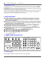
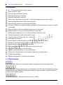
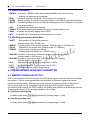
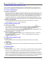
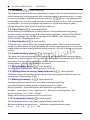
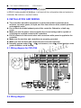
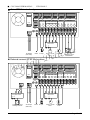
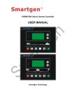
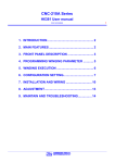
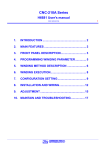
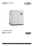
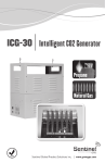
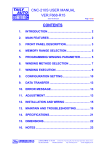
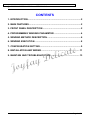
█
CNC-200A USER MANUAL
VER. H8681/3
CONTENTS
1. INTRODUCTION..............................................................................2
2. MAIN FEATURES ............................................................................2
3. FRONT PANEL DESCRIPTION ........................................................2
4. PROGRAMMING WINGING PARAMETER .......................................4
5. WINDING METHOD DESCRIPTION .................................................6
6. WINDING EXECUTION ....................................................................8
7. CONFIGURATION SETTING ............................................................9
8. INSTALLATION AND WIRING ........................................................ 11
9. MAINTAIN AND TROUBLESHOOTING .......................................... 13
Page 1 of 14
█
CNC-200A USER MANUAL
VER. H8681/3
1. INTRODUCTION
CNC-200A is a series of COIL WINDING MACHINE CONTROLLER developed by MINSU
AUTOMATION. It not only retains all the features of previous designs, it also has a low noise
level and is less sensitive to external power fluctuation.
CNC-200A also features an integrated design: putting stepper motor driver, DC motor speed
controller, brake and power supplier control circuits into one control box, simultaneously
achieving size reduction, high performance and low cost.
2. MAIN FEATURES
◆ Single chip Microprocessor design, has further higher performance and higher
functions; it also has less sensitive to external power fluctuation or to external
electromagnetic interference.
◆ Memory use FLASH ROM, capacity capable storing up to 1000 steps winding data,
9 winding parameters, and 5 options can be independently assigned for each step.
Off-power memory retention without battery.
◆ Winding speed can be specified using the front panel keypad, resulting in easy
programming of multi-step, multi-speed settings.
◆ Guiding traverse shaft stepper motor with a constant-current driver offering fast
wire guiding speeds.
◆ Guiding traverse shaft offering 10 steps moving speed selection.
◆ Software can be update through the personal computer.
◆ Power input AC100V~120V、220V~240V 600VA(max).
3. FRONT PANEL DESCRIPTION
READY
RUN
SLOW
MOVE
Q.S.
LAN
SHIFT
WIDTH
PITCH
STEP
RPM
RPM
TURNS
S.SLOW
E.SLOW
QTY
H.S.
L.S.
FUN
BRAKE
NEXT
PREV
IOUS
CNC-200A
DATA
SEL
START
STEP
7
8
9
EDIT
FEED
DIR
END
STEP
4
5
6
QTY
SET
WIND
DIR
AUTO
HOME
1
2
3
―
EDGE
STOP
AUTO
START
0
CLR
COPY
ENT
FINISH
ZERO
AUTO
MINSU AUTO
RESET
STOP
POWER
START
3.1. Power switch
Power supplier equipped, controls the AC power to the controller.
Page 2 of 14
█
CNC-200A USER MANUAL
VER. H8681/3
3.2. Key pads
~ :10 key, for entering numerical values.
:Enter into EDIT mode.
:Specify target production quantity.
:Specify starting step in memory.
:Specify ending step in memory.
:Select item of parameter during edit , or to switch display mode during running.
:Select guiding direction for each step during edit.
:Select winding direction for each step during edit.
:To specify whether to suspend winding, during the guiding traverse moving to the edges
of the width.
:Select whether to have auto-positioning function for each step.
:Select whether to have auto-starting function for each step.
:Reduce step number by one, or reduce production counter by one.
:During programming, clear current data to zero.
:Copy the data of previous step into current step.
:Write data into memory.
:Switch display to shows between production counter and speed (RPM).
:Hold down this key for two seconds to reset production counter.
:Switch between automatic and manual mode.
:Switch the brake between lock and unlock during motor stop.
:Skip current step and go to the next step.
:Discard current step and go to the previous step
:At any time, discontinues current operation and return to ready mode.
:Pause during winding.
:Restart during pause, or pause during winding.
3.3. Digital display
STEP DISPLAY:Show the current step number being wound or being programmed.
DATA DISPLAY:During programming, in combination with LED, shows the parameter being
programmed. During winding or ready mode, show the current number of turns or show the
guiding traverse shafts position.
COUNTER DISPLAY:Shows production counter or RPM.
Page 3 of 14
█
CNC-200A USER MANUAL
VER. H8681/3
3.4. Status indicators
□READY : Lit means in READY mode, flash means PAUSE mode, Not lit means
winding or programming in progress.
□RUN : Lit means winding in progress; not lit means not in progress.
□SLOW : During winding, lit means low speed winding; not lit means high speed winding.
□MOVE : Lit means guiding traverse is fixing the starting position for winding or is returning
to the home position.
□CUT : Lit means wire break, stop winding.
□FINISH: Will lit when reaching the preset production counter display count.
□RPM : Lit means the counter display shows RPM.
□QTY : Lit means the counter display shows production counter.
3.5. Winding parameters definitions
□SHIFT
: Start position of the guiding traverse.
[Setting range 0.00~ 999.99 mm].
□WIDTH : Guiding region of the guiding traverse . [Setting range 0 ~999.99 mm].
□PITCH : Diameter of the copper wire. [Setting range 0~ 9.999mm].
□TURNS : Total number of turns to be wound.
[Setting range 0.0~9999.9 or 0~99999 turns].
□S.SLOW : Number of turns to be wound at low speed, when start winding.
[Setting range 0~999.9 turns].
□E.SLOW : Number of turns to be done at low speed prior to stopping.
[Setting range 0~999.9 turns].
□H.S.
: High winding speed. [Setting range from 0~99%].
□L.S.
: Low winding speed. [Setting range from 0~25%].
□FUN
: Winding complete output signal setting.
4. PROGRAMMING WINGING PARAMETER
4.1. MEMORY RANGE SELECTION
CNC-200A contains 1000 memory step, by defining the region, users can effectively manage
the memory. Various winding parameter can be stored in different regions and can be
retrieved instantaneously. After specifying the regions, programming and winding can be
done in those regions; all un-selected regions will retain their original contents and
unmodified. When setting the STEP number, the Ending step number must be larger than the
Starting step number, or the winding operation will not start
◆ Specifying starting step
In ready mode, press
to selected. [Setting range 0 ~ 999].
◆ Specifying ending step
In ready mode, press
to selected. [Setting range 0 ~ 999].
Page 4 of 14
█
CNC-200A USER MANUAL
VER. H8681/3
4.2. Programming winding parameter
In READY mode, press
invokes the programming mode, the STEP DISPLAY shows
START STEP, the parameter indicator『SHIFT』lit, the DATA DISPLAY shows SHIFT setting
value, the SHIFT can be changed by pressing the numerical keys followed by the key.
After that the STEP number will automatically increase by one, to continue set the SHIFT for
next step. When the STEP number is larger then the END STEP , the STEP number will
restore to the START STEP and the indicator light will change from『SHIFT』 to『WIDTH』
to specifying the width for each STEP. Repeat the same procedure using numerical keys and
the key, all winding parameters for each STEP can thus programmed, after that
press key again to go back to ready mode.
The following functions are also available:
: To select guiding direction, forward or reverse.
: To select winding direction, clockwise or counter-clockwise.
: To specify whether to suspend winding when the guiding traverse moves to the two
edges of the width.
: To select whether guiding traverse move to the starting position automatically or upon a
manual pressing of the
key.
: Select whether to have auto-starting function for each step.
: Clear the setting value .
: Copy the content of the previous step to the current step.
: Go back to the previous step.
: To scroll through different parameters.
Each time when change the parameters and selections,
key must pressed to effect
the change.
4.3. Guiding traverse shaft introduce setting
During set the 『SHIFT』, 『WIDTH』 and 『guiding traverse travel limit』, can use numeric
keypad to set location data or can also use ,
or ,
keys to leading the guiding
traverse shaft location.
4.4. Clear all winding parameter
In the READY mode, press
will clear all the winding parameter in the memory. Be
cautious in using this function or all the data will be lost.
Page 5 of 14
█
CNC-200A USER MANUAL
VER. H8681/3
5. WINDING METHOD DESCRIPTION
Prior to winding, the general winding principles are explained below so the operators can
have a better understanding of the performance of the controller and make better use of it.
5.1. Turns counting mode
◆ Absolute counting mode
Winding spindle shaft is capable of fixed-point stopping. Upon each restart, the turn count
will reset only the integer portion of the turn’s to zero, with the decimal unchanged. For
example, for a previous number of 100.3 turns, when restarting the next step winding, the
counting will start with 0.3 to avoid accumulation of spindle shaft free play error from
consecutive windings. This counting method may cause insufficient winding by one turn.
Therefore, when starting from 0.9, the spindle will turn to the 0.0 before it starts counting.
◆ Relative counting mode
This counting method zeros the counter upon each restart, therefore it is easy to
understand and will not cause insufficient winding.
5.2. Special Wire-guiding mode
◆ Interlace wire-guiding
If the『WIDTH』of the step is zero, the wire-guiding becomes interlace mode. When it
begins winding, the wire-guiding will follow the wire direction to proceed two wire
diameters and regress one wire diameters cyclically until the step of winding ends. This
mode especially suits the inductor winding.
◆ Non wire-guiding
Sometimes, the winding device may be used to winding adhesive tapes or copper foil.
When the wire-guiding is not needed, 『PITCH』may be adjusted to zero and the
wire-guiding won't be move.
5.3. Start switch operation mode
◆ ON-OFF mode
Press down start switch to start winding and release start switch to stop winding
immediately.
◆ Trigger mode
Press and release start switch once to start winding, press and release start switch again
to stop winding
5.4. Running mode
◆ Continual mode
Before it begins winding, if『SHIFT』of the step set as 999.99, then the starting position,
the width , the wire-guiding direction and the winding direction won't be re-read. The
values are not changed, that is the wire guiding will continue guiding wires on the same
position. The width and left-right margins are the same as the ones of the previous section.
Both the wire-guiding and winding directions are not changed either. This mode especially
suits to winding which have the multiple drawing tops in the same sets of coils.
Page 6 of 14
█
CNC-200A USER MANUAL
VER. H8681/3
◆ Edges slow mode
The winding speed will slow down before the guiding traverse reach to the two edges of
the width (work with『E. SLOW』turns). After the guiding traverse veered, then restore to
hi-speed winding. (Refer to the section 7.1. edge slow mode).
◆ Automatically circularly mode
If key set to on, it means Automatically circularly mode, in this mode when finish a
step of winding it will automatically get into next step and start winding without
press
key (work with
and
keys).
5.5. How to set winding turns accurately
◆ Preset method
Set the 『E.SLOW』to zero first and then set the 『TURNS』to the desired number. Set
proper parameters according to copper wire, bobbin, tension, etc, then press to start
winding. When finished, obtain the actual number of turns and calculate the number of
overshot turns. Go into programming mode and subtract the number of the overshot turns
from the 『TURNS』to obtain the required setting.
This method has a higher throughput, however, the resulting stopping location may not be
precise.
◆ High-Low speed method
This method uses a combination of 『H.S』『
/ L.S.』and 『E.SLOW』to achieve the desired
number of turns.
The『L.S.』 should not be too high. The number of 『E.SLOW』turns must be adequate
to allow the spindle shaft to slow down to low speed before reaching the total number of
turns. This can result in precise stopping location.
◆ Double-brake method
As the winding turns of the winding shaft reach the numbers of the『E.SLOW』, brake for
a short period first. After the winding shaft stops, continue winding at low speed.
Therefore the numbers of the slow speed may be reduced and the efficiency of winding
may be increased,
(Refer to the section 7.1. braking mode).
Page 7 of 14
█
CNC-200A USER MANUAL
VER. H8681/3
6. WINDING EXECUTION
6.1. To start winding
After set up all data items, press
set-up content. Press
key, the winding process begins in accordance with the
key to pause winding. During winding, press the
key, the winding
speed can be switch between high speed and low speed.
The following key functions are available during PAUSE mode:
: Give up the numbers of the winding turns and regress one step.
: Finish current step and proceed to next step.
: Continue winding.
: Give up winding and go back to the READY mode.
6.2. Change the display mode
During winding or during PAUSE mode, press
key, the DATA DISPLAY can be change the
display mode between turns or guiding traverse position.
6.3. Winding speed (RPM) display
Pressing
key will cause the PIECE COUNT DISPLAY to display the spindle shaft RPM
without interrupting the counting. Pressing
again will change the PIECE COUNT DISPLAY
back to displaying the piece count.
6.4. Production counter management
Upon turning on the power, the counter display will show the production counter. During
wining, each time the winding process goes from the START STEP to the END STEP, the
counter will automatically increase by one.
◆ Preset production counter:
In READY mode, press key once and key in desired values
followed by the
key. During winding when the production counter reaches the preset value, the FINISH
led will lit. [Setting range 0~99999].
◆ Decrease production counter:
During READY or PAUSE mode, press the
key and hold down for two seconds the
piece counter will decrease by one.
◆ Reset production counter:
In any time holding down key for two seconds, it will set the piece counter to zero.
Page 8 of 14
█
CNC-200A USER MANUAL
VER. H8681/3
7. CONFIGURATION SETTING
CNC-200A is a multi-purpose design, to meet various requirements; additional settings are
configured to provide flexibility for additional applications.
In the READY mode, press the following keys combination as section [7.1. ~7.10], the DATA
DISPLAY will show corresponding setting value. If no change is necessary, press the key
get back to READY mode. Or press key to get into change mode, then the parameter can
be changed by pressing the numerical key followed by the
7.1. Winding mode selection
key.
Initial value[10010100]
In this function the STEP display and the DATA display will shows eight digits, representing
eight winding mode selections respectively.Press numerical keys as below to set each digit.
8
7
6
5
4
3
2
1
NO Function
Control Mode:Select control mode of winding spindle driver.
0 represents CW=Forward/Stop, CCW=Reverse/Stop.
1 represents RUN=Motion/stop, DIR=Forward/Reverse,
Counting mode:Select the counting mode of the winding spindle shaft.
0 represents with zero point and using absolute counting mode.
1 represents without zero point and using relative counting mode.
2 represents with zero point and using relative counting mode.
3 represents without zero point and using absolute counting mode.
Edge slow:Slow down the winding speed before the guiding traverse reach to the two
edges of the width.
0 represents not slow down; 1 represents to slow down.
Braking mode:Select the braking mode of the winding spindle.
0 represents single brake mode; 1 represents double brake mode.
Counting unit:Select 0.1 or 1 turns as your count unit.
0 represents 0.1(0.0 to 9999.9 turns); 1 represents 1(0 to 99999 turns).
Guiding traverse unit:Select the basic unit of guiding traverse.
0 represents mm; 1 represents inch (must using lead screw in imperial).
Operation mode:Select operation mode for the START switch.
0 represents ON-OFF mode; 1 represents Trigger mode.
The key on the front panel always as the Trigger mode.
7.2. Station number
Initial value[0]
[Setting range 01~99].
Page 9 of 14
█
CNC-200A USER MANUAL
7.3. Password
VER. H8681/3
Initial value[0000]
This password is used to protect the setting data in memory. After you set this password, you
cannot change any winding parameter and configuration data in normal sequence. You have
to key in four numbers of password before press the , , , keys. If the password has
been passed once, you can change any data in normal sequence until you turn off the power
or press key. You must to remember the password or you cannot change any data.
[Setting range 0000~9999]. Set 0000 means no password.
7.4. Travel limit
Initial value[999.99]
Set the maximum travel distance of guiding traverse. During winding when the guiding
traverse reaches this position, the motor stop winding immediately, and the DATA DISPLAY
shows error massage, then RESET and go back to the READY mode. [Setting range
000.00~999.99]. 999.99 Means no limit.
7.5. Fixed location
Initial value[1]
To set how often, must be correct the guiding traverse location. Each time when finish this
number of product pieces, the guiding traverse will moves to the home position to correct the
location before moving to starting position.[Setting range 00~ 99]. Set 00 means not to do this
function.
7.6. Limited winding speed
Initial value[0]
This value is to limited winding speed and make sure the winding spindle shaft and guiding
traverse are in synchronization. The controller uses this value to calculate with wire PITCH of
current step, and then to limited maximum winding speed of current step.
[Setting range 0~ 99999]. Set 0 means no limit speed.
7.7. Brake holding time
Initial value[0.3]
To set the hold times for brake. [Setting range 0.1~9.9 sec].
7.8. Guiding traverse moving speed selection
Initial value[20]
The speed at which the guiding traverse moving to the starting position and returning to the
home position. [Setting range 0~99].
7.9. Moving increment
Initial value[2.00]
Guiding traverse moving increment. This value is calculated according
to the specification of winding machines.[Setting range 0.01~99.99].
Moving increment=(Screw pitch×Gear ratio÷Resolution of guiding motor)
Example: Screw pitch=5mm、Gear ratio=1.6、Resolution of guiding motor=400
Moving increment=5×1.6÷400=0.02mm
Setting value= Moving increment×100=0.02×100=2.00
7.10. Acceleration times
Initial value[0]
Set the accelerate times for the winding spindle [Setting range 00~99].
00 means shortest acceleration times ;99 means longest acceleration times.
T(ms)=(H.S.-L.S.)×【(N+1)×2】
Page 10 of 14
█
CNC-200A USER MANUAL
VER. H8681/3
7.11. Reset all configuration data
In READY mode press
keys, it will reset all the configuration data and replace by
initial data. Be cautious in use this function.
8. INSTALLATION AND WIRING
◆ The controllers should be operated in an environment that is protected from
moisture, corrosive gases, or liquid, and free from airborne dust, metallic particles,
and magnetic noise.
◆ Do not block the intake/exhaust ports of the controller. Otherwise, a fault may
occur.
◆ Make sure that the power source supplies the correct voltage and is capable of
supplying the required current to the controllers.
◆ Do not connect or disconnect wires and connectors while power is applied to the
controller.
◆ Make sure the machine and controllers are properly grounded.
◆ Make sure that the leads and connectors are connected correctly.
◆ Normally operate under 10℃ ~ 40℃ environment; over 40℃ should perform under
good ventilation, avoid heating.
8.1. Wiring diagram for CN2~CN6
TR
TR +
+24V
RESET
START
STOP
LAMP 3
LAMP 2
LAMP 1
COM
IP 6
HOME
IP 5
+24V
COM
PHC
PHB
PHA
+24V
+24V
OP 1
OP 2
OP 3
OP 4
IP 1
IP 2
IP 3
IP 4
COM
RS-485
Operate Switches
Home Sensor
Turn Counter
AUX I/O
CN7
CN2
CN3
CN4
CN5
CN6
CN3
CN4
CN5
CN6
-
OV
DIR
PUS
+5V
Pulse Output
CN7
CN8
COM
IP4
IP3
+ 24
IP2
IP1
OP1
OP2
IP5
OP3
IP6
OP4
1
2
FOOT SW
AUX I/O
a
a
b
3
1
b
4
3
2
1
STOP
a
b
4
3
4
2
1
2
START
RESET
Operate switches
1
1
HOME-SR
Home sensor
CNTB-03B
Turn counter
8.4. Wiring diagram
Page 11 of 14
█
CNC-200A USER MANUAL
VER. H8681/3
◆ Drive STEP Motor in directly
+24V
RESET
START
STOP
LAMP 3
LAMP 2
LAMP 1
COM
IP 6
HOME
IP 5
+24V
COM
PHC
PHB
PHA
+24V
+24V
OP 1
OP 2
OP 3
OP 4
IP 1
IP 2
IP 3
IP 4
COM
RS-485
Operate Switches
Home Sensor
Turn Counter
AUX I/O
CN7
CN2
CN3
CN4
CN5
CN6
CN8
AC Input
1
2
3
STEP Motor
RUN
F/R
H/L
BK+
BK-
A
A
B
B
4
5
6
7
8
9
10
11
12
H/L
Vin
AC
Brake
CCW
AC
Winding Driver
COM CW CCW Vout
CW
AC Output
-
TR
TR +
Pulse Output
AC
GND
AC
CN8
OV
DIR
PUS
+5V
CN7
GND
CN8
COM
AC
GND
AC
Motor Driver
AC
AC
A
A
M
AC Output
EARTH
AC Input
B
2Phase 6V 2A
Guiding Traverse
DC24V 12W
Winding Spindle
Motor
(MAX 400W)
B
STEP Motor
◆ External connect STEP Motor driver
+24V
RESET
START
STOP
LAMP 3
LAMP 2
LAMP 1
COM
IP 6
HOME
IP 5
+24V
COM
PHC
PHB
PHA
+24V
+24V
OP 1
OP 2
OP 3
OP 4
IP 1
IP 2
IP 3
IP 4
COM
RS-485
Operate Switches
Home Sensor
Turn Counter
AUX I/O
CN7
CN2
CN3
CN4
CN5
CN8
AC Input
AC
1
2
3
CN6
Brake
STEP Motor
RUN
F/R
H/L
BK+
BK-
A
A
B
B
4
5
6
7
8
9
10
11
12
H/L
Vin
AC
Winding Driver
COM CW CCW Vout
CCW
AC Output
-
TR
TR +
Pulse Output
AC
GND
AC
CN8
OV
DIR
PUS
+5V
CN7
GND
CN7
CN8
Motor Driver
A
B
AC
AC
DC-
DC+
A
CW
COM
AC
GND
AC
DIR
PUS
V+
Step Motor Driver
M
B
2Phase STEP Motor
AC Output
Guiding Traverse
(MAX 400W)
EARTH
AC Input
Winding Spindle
Motor
DC24V 12W
Brake
Page 12 of 14
█
CNC-200A USER MANUAL
VER. H8681/3
9. MAINTAIN AND TROUBLESHOOTING
9.1. Periodically maintain
◆ Please periodically clean up the controller inner accumulate dust and dopants.
◆ Please periodically check the wire connection between controller and machine if
have loose or bad contact.
◆ The following parts must be maintained or changed periodically as list below. If any
part is found faulty, it must be changed immediately even when it has not yet
reached the end of its life, which depends on the operating method and
environmental condition.
◆ For parts replacement, please contact your sales representative.
9.2. Error message
When a fault occurs during operation, the DATA DISPLAY sho ws error massage, stop
winding and then RESET go back to the READY mode.
Err-0: The parameters or data in memory are fault.
Err-1: The『SHIFT』value sets exceed the Travel Limit.
Err-2: During winding, the guiding traverse to exceed the Travel Limit.
Err-3: During winding, the guiding traverses reach to the Home sensor.
Err-p: Password error, key in 4 numbers password before edit.
9.3. To abort seeks the original position
At boot and reset procedures, if because of unknown reason however engender the winding
shaft and guiding traverse can't find out the original position and make the controller can't get
into ready mode, can press key to abort seeks the original position, make controller get into
ready mode.
9.4. Troubleshooting
This section provides information to guide the user in understanding different fault condition
and their general troubleshooting procedures, and with their possible solutions.
◆ Do not connect or disconnect wires and connectors while power is applied to th e
controller.
◆ Make sure that the leads and connectors are connected correctly, before doing the
troubleshooting procedures.
◆ Do not remove welded parts on the PC board without appropriate tools.
NO
1
Fault Description
Power ON, but the display
shows nothing.
Correctives Action
a. Check AC power input.
b. Check the LED lamp on TLP-503D power supply, if
not lit replace TLP-503D
c. Replace 200A-CPU.
Page 13 of 14
█
CNC-200A USER MANUAL
2
3
4
Power ON, but the display
shows confusion massage
Power ON, but winding
spindle didn’t rotate, or
cannot stop rotation, And
controller cannot get into
ready mode.
Power ON, but guiding
traverse didn’t move or
cannot stop moving, And
controller cannot get into
ready mode.
VER. H8681/3
a. Replace 200A-CPU.
a. Press
o make the controller get into READY
mode.
b. Check the winding parameter『L.S.』setting value of
START STEP
c. Replace turns counter CNTB-03B.
d. Replace 200A-CPU.
a. Press to make the controller get into READY
mode.
b. Replace HOME SENSOR.
c. Replace 200A-DVR.
d. Replace 200A-CPU.
a. Check the READY LED lamp if not lit, do
procedures number 3 and 4.
b. Key in four numbers password before edit, if the
password has been set before.
c. Replace 200-KBD.
d. Replace 200A-CPU.
a. Replace 200A-CPU.
5
Cannot edit parameters.
6
Display shows Err-0, then
reset, and get into READY
mode.
7
Display shows Err-1/Err-2
then reset and get into
READY mode.
a. Check winding parameters『SHIFT』and『WIDTH』
Display shows Err-3,
then reset, and get into
READY mode.
a. Check winding parameters『SHIFT』and『WIDTH』
8
setting value.
b. Check configurations 『TRAVEL LIMIT』setting
value.
setting value.
b. Replace HOME SENSOR.
a. Check wire connections of brake.
b. Replace brake.
c. Replace 200A-DVR.
9
Brake failure.
10
Winding spindle can
not switching winding
direction.
a. Check configurations 『Winding spindle control
Counting failure. Replace
turns counter CNTB-03B.
Guiding traverse moves
half pitch or double
pitch.
Replace 200A-CPU.
11
12
mode selection 』setting value.
b. Replace 200A-CPU.
Check Configurations『Moving increment』setting
value.
Page 14 of 14