1
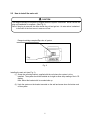
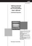
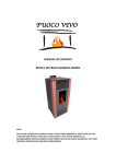
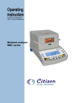
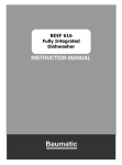
COLORMETRY
CMU-124H
Installation and Start-Up
User’s Manual
MIURA BOILER WEST, INC.
IN OUR CONTINUING EFFORT TO IMPROVE OUR
PRODUCT, INFORMATION IN THIS MANUAL MAY BE
CHANGED WITHOUT NOTICE.
PRODUCTION REVISED SEPTEMBER 2000
Introduction
We appreciate your purchase of the Colormetry system.
This user’s manual covers instructions for the use of your Colormetry system. Please read
through this manual and understand the contents before using the system.
We also recommend that the manual be kept nearby for reference when operating the
Colormetry system.
Operate the system only in accordance with the instructions given in this manual.
We will under no circumstances whatsoever be liable for damages arising from the user's failure
to follow the instructions given in this manual.
(Some details of the instructions contained in this manual may be different from the actual
system purchased. The instructions are also subject to change without prior notice.)
CAUTION
The Colormetry system is a hardness-leakage monitoring system that monitor the harness of
water and issues hardness-leakage alarm. It is not a system that remedies (effects recovery
from) hardness leakage itself.
i
How this manual is organized
This manual consists of ten chapters listed below. We recommend that you familiarize yourself
with the objectives and contents of each, and keep the manual handy for reference.
Organization
Chapter 1
Safety Warnings and Precautions
Explains the danger and precautionary signs and notes that apply to the
handling, installation, wiring and maintenance of the Colormetry system.
Chapter 2
Installation
Shows how to install and wire the Colormetry system.
Chapter 3
Settings and Start Up
Guides you from setting up through test run.
ii
Table of contents
Chapter 1
Safety warnings/Precautions........................................................................... 1
Chapter 2
Installation......................................................................................................... 3
2-1
2-2
2-3
Preinstallation checklist .............................................................................................................. 4
How to install the main unit......................................................................................................... 5
Plumbing ..................................................................................................................................... 7
2-3-1
2-3-2
2-4
DRAIN PIPE (SEE FIG. 4) .................................................................................................... 7
WATER-SUPPLY LINE (SEE FIG. 5.).................................................................................... 8
How to wire the system............................................................................................................. 11
2-4-1
2-4-2
2-4-3
2-4-4
2-5
ROUTING THE WIRES (SEE FIGURE 7) .............................................................................. 11
EXTERNAL-ALARM MASTER CONTACT OUTPUT.............................................................. 13
REMOTE SIGNAL INPUT ................................................................................................... 14
IN-MONITORING OUTPUT ................................................................................................. 15
Installing the reagent cartridge ............................................................................................... 16
2-6
Final checking of installation and wiring before startup ............................................................ 18
Chapter 3
3-1
3-2
Settings and start up ...................................................................................... 20
Setting the system before starting it ......................................................................................... 21
Checking the system operation and settings immediately after turning on the power ............. 23
3-2-1
3-2-2
3-3
3-4
3-5
TURNING THE POWER ON ................................................................................................ 23
STATUS-VERIFICATION TEST MODE ................................................................................ 25
About items to be set in Setting mode...................................................................................... 26
Verifying monitor operation....................................................................................................... 31
Verifying the issuance of an abnormality alarm........................................................................ 32
iii
Chapter 1 Safety Warning/Precautions
Explains the danger and precautionary signs and notes that apply to the handling,
installation, wiring and maintenance of the Colormetry system.
1
This sign indicates a situation in
which incorrect handling might
result in death or injury to the
operator, or that may result in
damage to property.
WARNING
This sign indicates precautions
for the prevention of damage to
the equipment.
CAUTION
Instructions for effective
operation and information that
may become useful are
explained here.
NOTE
2
Chapter 2 Installation
Shows how to install and wire the Colormetry system.
2-1
Preinstallation checklist ...................................................................................4
2-2
How to install the main unit .............................................................................5
2-3
Plumbing .........................................................................................................7
2-4
How to wire the system .................................................................................11
2-5
Installing the Reagent Cartridge....................................................................16
2-6
Final checking of installation and wiring before startup ................................18
3
We recommend that the user read this chapter before installation of the Colormetry for
safety operation.
2-1 Preinstallation checklist
[1] The raw water pressure range (both static and dynamic) must always be 7.1 to 71 psi
(0.05 to 0.5 Mpa) (0.5 to 5 kg/km2). If the pressure is outside that range, a
pressurizing unit or pressure-reducing valve will be required.
[2] Use the system with raw water in the 41 to 104°F (5 to 40°C) range. Using water
outside that range may damage the internal components.
[3] Use the system in an ambient temperature range of 41 to 122°F (5 to 50°C).
Temperatures outside this range may cause deterioration of the reagent.
[4] The system is designed to hang on a wall. Install it indoors, away from rain.
[5] Avoid a location subject to direct sunlight.
[6] Install the system in such a way that the length of feed-water line between the water
softener and the system is within 16.4 ft (5 m).
[7] The power supply is specified at AC 24 V, 20 W. A source is required near the
system.
[8] The Polyethylene drain pipe included in the system is 9.8 ft (3 m) long, requiring a
nearby drainage trough.
[9] Provide sufficient work space around the installed system for maintenance and
operation.
4
2-2 How to install the main unit
CAUTION
The reagent cartridge’s receptacle is plugged when the system is delivered. Never remove the
plug until installation is complete. (See Fig. 2.)
Note: If the plug is removed, the stirrer inside may roll and get lost. An extra stirrer is attached
to the back of the front cover in case one is lost.
Reagent-cartridge receptacleTop view of system
Plug
Fig. 2
Installing the main unit (see Fig. 3)
(1) Screw the mounting bracket, supplied with the unit where the system is to be
installed. The system should be installed at a height to allow easy reading of the LCD
display.
Note: Mount the bracket with its rounded side up.
(2) Hook the system on the bracket mounted on the wall and screw down the bottom end
of the system.
5
Installed system side view
Side view of system
Mounting
bracket
Rounded
corner
Screw
holes
3/16” (5.5
mm) dia.
Mounting screw
centers 8-3/4”
(224 mm)
@Mounting
bracket@
Wall
Mounting
bracket
Bottom
plate
Screw
holes
3/16” (5.5
mm) dia.
@ Mounting
Fig. 3
Bottom view of system
Side view of system
Cylindrical
part
Drain hole
Cylindrical part
Make sure the receptacle area
is free of deformation and burrs
Filter installation
Fixing screws for front cover
Polyethylene pipe, 5/16“ (8 mm) dia.
Fig. 4
6
Drainage trough
2-3 Plumbing
2-3-1 Drain-water pipe (see Fig. 4)
(1) Cut the included polyethylene pipe, 5/16” (8 mm) dia., to the length required for
drainage.
(2) Insert one end of the polyethylene pipe into the tubular connection at the bottom of
the system. Run the other end into a drainage trough.
Note: The insertion of the polyethylene pipe into the tubular connection and the
bottom requires some force. Check the connection for excessive deformation
or burrs before inserting the pipe.
CAUTION
z Do not connect the drain-water pipe to other plumbing.
z Be sure to drain it to the open air.
z Exercise care in keeping the drain-water pipe free of kinks.
An obstructed drain-water pipe may cause water leakage and misevaluation.
CAUTION
In case the drain-water pipe is clogged and the internal pressure builds up, the system will
relieve the pressure through either of the methods (1) and (2) shown below. These methods
cause drain water to leak down through the bottom of the system. Be sure not to leave
anything underneath the system.
(1) Water leaks out of the pipe connection at the bottom.
(2) Water leaks out of the internal piping.
Water will drain out of the drain holes in the bottom of the system.
7
2-3-2 Feed-water line (refer to Fig. 5.)
(1) Take the feed-water line off the outlet side of the water softener. (The feed-water line
connection may be made to the water softener’s water sampling valve.)
(2) Precut the included polyethylene pipe, 1/4” (6 mm) dia., to the length required for the
installation, and firmly insert the end into the tube coupling.
(3) Assemble the filter according to the following procedure (see Fig. 6):
[1] Take the filter-casing assembly out of the bag. Remove the tape from the end.
Note: There is a constant-flow regulator valve installed at the end of the casing.
Be careful not lose the valve during installation.
A spare constant-flow regulator valve is attached to the filter-cartridge box.
The spare may be used to replace a lost valve.
[2] The filter casing comes apart into two sections. To take them apart, rotate the
top and bottom sections in the direction of arrow.
[3] Remove the filter cartridge from the box (bag). Align the outlet end of the
cartridge in the center of the top casing. Insert the cartridge all the way, then
firmly tighten the bottom casing.
(4) Insert the polyethylene pipe firmly into the tube coupling on the bottom casing.
(5) Screw the filter casing into the bottom plate on the system. There is no need for
concern about tightening it hard, since the O-ring at the end of filter casing will provide
a good seal.
(6) Use the included cable ties to bundle the 1/4” (6 mm) dia. Polyethylene pipe to the
5/16” (8 mm) dia. polyethylene pipe.
(Doing so will prevent the 5/16” (8 mm) pipe from dropping out of the system if
external force is exerted upon it.)
Bundle them together about 6 to 8 inches (150 to 200 mm) away from the bottom of
the filter casing. If it is tied too close to the filter casing, undue prying force may be
exerted on the tube coupling and cause a leakage.
CAUTION
Exercise care in keeping the pipe free of kinks.
8
Ball valve
Water softener
Additional plumbing
Tube coupling
1/4 (6) dia.
Polyethylene pipe
Filter casing (bottom)
Tube coupling
Cable tie
Existing watersampling valve
5/16 (8) dia.
Polyethylene pipe
Fig. 5
CAUTION
Where zinc or copper plumbing is used, zinc or copper ions would dissolve and stagnate in the
water. The reagent in this system reacts with zinc and copper ions. Take the sample water as
close to the water softener as possible to avoid the effects of ions dissolving out of the
plumbing.
9
Filter casing Assy
Tape
Constant-flow
regulator valve (the
black rubber plate
Outlet
Filter cartridge
Filter casing (bottom)
Tube coupling
1/4 (6) dia.
Polyethylene pipe
Filter casing (top)
Front view of system
Before screwing in the filter,
be sure that the constantflow regulator valve is
Screw it into the bottom
plate with the 1/4” (6 mm)
polyethylene pipe attached.
Bundle the tube together
with a cable tie.
Tie about 6 to 8 inches (150
to 200 mm) away from the
bottom of the filter casing.
Fig. 6
10
2-4 How to wire the system
2-4-1 Routing the wires (See Fig. 7)
(1) Loosen the screw at the bottom of the system and remove the front cover.
(2) Pass the wires through the wire holder and wire hole in the bottom plate. Gather and
connect the wires to the terminal block on the circuit board.
(3) Provide a drooping slack in the wires, and clamp them down.
WARNING
z Use a dedicated power supply line having the specified capacity. Insufficient capacity may
cause a fire.
z Provide a ground fault interrupter with an overcurrent-protection function to prevent electric
shock.
z Use a wire of 0.75 mm2 or a larger cross section, or the wire may overheat and cause a
fire.
z Ground the grounding terminal to prevent electric shock and malfunction.
z Be sure to clamp the wires down, or undue force exerted on them may damage the
system.
z The wires must have a drooping slack to prevent leaked water from running down the
wires and causing a short circuit.
Front view of system
Terminal block (see Fig. 8)
(Connect wiring as
required by the site.)
In-monitoring
output terminal
Wiring window
Bottom view of system
Front cover’s
fixing screw
Wire holder
Wiring hole
Wire holder
Fig. 7
11
Clamp the wires
Provide a drooping
slack for the wire
CAUTION
The system starts operating as soon as the power is turned on (system is plugged in). Activate
it only when it is ready for a test run.
1
2
3
External-alarm
master output
AC 24V, 1A
4
5
6
Remote
FG
signal input (Ground)
AC 24V
7
8
Power supply (power
transformer)
AC 24V, 50/60Hz
(Connect the included
power transformer to
terminal nos. 7 and 8.)
Transistor
D1 D2 FG M+ MNot used
In-monitoring output (DDI-Compatible)
Fig. 8
12
2-4-2 External-alarm master contact output
z
This is a SPDT contact. Connect it as required in the installation.
Contact capacity: AC 24 V, 1 Amp.
Note: If an inductive load such as a relay is used, connect a spark suppresser (CR or
a varister) across it.
z
A boiler equipped with a BR1 controller model LX, EX or WX can be configured as
shown in Fig. 9 to indicate a caution, “Check softener” message on the boiler display
in case of an abnormal condition alarm or a Colormetry system error.
Terminal block in Colormetry
1
2
3
4
Be sure to remove the
shorting jumper
78 79 80 81 82 83
Water-softener monitoring
circuit
Terminal block in BG1 boiler
Fig. 9
13
2-4-3 Remote signal input (Refer to Section 3-3, “About the use and examples of remote signals,“ on
page 14 of the General Information manual for remote signal functions, and connect a signal to suit
the installation.)
Connecting a contact AC 24 V with voltage (AC 24 V) enable the system to remotely
control the starting and stopping of monitoring.
In addition, a remote signal may be utilized in either mode -- the on state or off state - to
start or stop monitoring. (Either the “a” or “b” contact may be used.)
Wire a voltage input (AC 24 V) as shown in Fig. 10, and a nonvoltage input as described
in Fig. 11, below.
3
4
5
6
Remote signal
(“a” or “b” contact with voltage)
3
4
5
6
7
8
Remote signal
(“a” or “b” contact without voltage)
AC24V
Fig. 11
Fig. 10
If no remote signal is connected, monitoring will be performed automatically at the monitor
interval set in the LCD display.
CAUTION
z If a contact representing the feeding of water is available, connect this on a highest priority.
If not, set up the start and stop time on the LCD display to avoid monitoring during water
stoppage and softener regeneration, or a system error may occur.
14
2-4-4 In-monitoring output
This is an open-collector output that turns on only during the monitoring process to
indicate that monitoring is in progress.
External DC power supply is required.
Capacity: DC 24 V, 70 mA.
See Fig. 12 to connect the output as required.
Note: A built-in diode-type
DC relay (24 V, max.)
FG M+ M-
DC power source (24 V, max.)
Fig. 12
Note: A DC relay with a coil-type surge-suppressing diode is recommended.
If an ordinary type DC relay is to be used, connect a diode in parallel with the relay.
CAUTION
Turning a relay on and off generates sufficient back EMF across its coil to destroy a transistor
on the opening of the relay. Be sure to connect a surge suppresser in order to protect the
transistor.
15
2-5 Installing the reagent cartridge
(1)
(2)
(3)
(4)
(5)
Remove the plug from the reagent cartridge receptacle in the system.
Completely pull out the cartridge lever, which is located at the front of the system.
Take the reagent cartridge out of its box (bag).
Insert the reagent cartridge into the receptacle firmly.
Push the cartridge lever back in and check to see that it is returned into the system.
Note: If the reagent cartridge lifts up when the cartridge lever is pushed in, insert the
cartridge all over again.
Note: If the bottom of the horizontal line in the cartridge’s surface design is not lined
up approximately with the edge of the cover on the main unit, insert the
cartridge over again.
CAUTION
z Before installing a reagent cartridge, always check the manufacture date on the package.
(The cartridge life is about one year from the date of manufacture, and is used up within
approximately four months of installation.)
z When installing a reagent cartridge, push it in slowly, keeping the nozzle and check tube
from hitting the main unit.
z Be sure to push the cartridge lever back into the main unit, or the cartridge may come off
and water may leak when water pressure is applied during operation.
z Never remove the check tube from the end nozzle of the reagent cartridge. Do not touch
the check tube. Otherwise, the reagent injection volume may be affected.
2. Insert the cartridge
1. Pull out the cartridge
lever
Reagent
cartridge
receptacle
3. Push the cartridge
lever
Reagent
cartridge
Top view of system
Tube (rear
opening)
Tube
Front view of system
Cartridge
lever
Bottom of
horizontal
design line
The bottom
of the
horizontal
line
approximatel
y lines up
Edge of cover
Fig. 13
16
WARNING
z
z
z
z
Do not use the reagent cartridge for the use other than the Colormetry system.
Never disassemble the reagent cartridge. Reagent may splatter onto the skin or the eyes.
Dispose of the fully intact reagent cartridge as plastic refuse.
If the reagent gets on the skin or in the eyes, rinse immediately with water.
17
2-5
Final checking of installation and wiring before startup
Checking the installation condition
(1) The Colormetry system is designed for indoor installation only. Is the installation free
of rain water and out of direct sunlight?
(2) Is the operating environment appropriate (water pressure, water temperature and
ambient temperature)?
(3) Is the system firmly attached to a wall surface, etc.?
(4) Is the reagent cartridge correctly installed and the cartridge lever positively locked in?
(5) Is the filter assembly installed correctly?
[1] Is the fiber filter cartridge set in the filter casing?
[2] Is the orifice (a black rubber plate) installed at the end of the filter casing?
[3] Are the top and bottom halves of the filter casing tightly assembled together?
[4] Is the filter assembly correctly mounted on the main unit?
(6) Is there anything under the system that should not get wet?
(7) Is the system free of excessive scratches or dirt?
Checking the wiring
(1) The system is specified for AC 24 V at 20 W. Is the accessory transformer for
converting AC 110 volt to 24 volts installed? Is the power-supply line correct (voltage,
capacity and wire diameter)?
(2) Is a ground fault interrupter with overcurrent protection installed in the power-supply
line?
(3) Is the system’s grounding terminal connected?
(4) Are the wiring connections correct?
(5) Is the wiring provided with a drooping just ahead of clamping point?
(6) Have the terminals been retightened to be sure?
Checking the plumbing
(1) Are the feed-water and drain-water pipe connections correctly made?
(2) Are the feed-water and drain-water pipe free of kinks and flattening?
(3) Is the drain-water pipe open to the air and independent of other plumbing?
(4) With the water pressure turned on, are there any leakage in the connections?
CAUTION
Be sure to perform the checks listed in the foregoing before startup.
18
System operating environment
z The specified ambient temperature
range is 41 to 104°F (5 to 40°C).
z Operate the system indoors only.
z Avoid direct sunlight on the
z Store the cartridges in a cool, dark
place.
z Do not disassemble a cartridge.
z Do not pull the cartridge during the
monitoring process.
z If the reagent gets on the skin or in the
eyes, rinse it off with water
immediately.
z Insert a reagent cartridge
after pulling up the lever.
Push the lever back into the
main unit after inserting the
cartridge. Verify that the
lever is pushed into the main
unit.
z Do not touch the pipe at the tip
and another at the opening.
z Do not remove the plug until
installation is complete.
z Do not use.
z Do not press the switch hard
or press it with a sharp
object.
z Be sure to install the front
cover after the test run.
z Do not use (only D1, D2 and FG).
z Be careful to avoid electric
shock during the test run.
z Set the system at the time of
the test run.
z Connect the wiring here.
z Lightly tighten together the top and
bottom halves of the filter casing.
z Be sure to clamp the wires.
z Exercise care in arranging the
pipe, without making it bend.
z Be sure to provide a
drooping slack once.
z Be sure to drain it into the open air.
z The specified raw water pressure (both static and dynamic) range is 7.1 psi
to 71 psi (0.05 through 0.5 Mpa).
z The specified temperature range of supply water is 41 to 104°F (5 to 40°C).
19
Chapter 3 Setting & Start up
Guides you from setting up through test run.
3-1
Setting the system before starting it..............................................................21
3-2
Checking the system operation and settings immediately
after turning on the power .............................................................................23
3-3
About items to be set in Setting mode ..........................................................26
3-4
Verifying monitor operation ...........................................................................66
3-5
Verifying the issuance of an abnormality alarm ............................................67
20
3-1 Setting the system before starting it
The items described below must be set in order for the system to operate properly.
The system will operate as set at the factory. However, change the settings as required
for each installation.
Setting the DIP switch
Before turning the power on, open the front cover in the main unit and check the Dipswitch setting. Change the setting as required. (See Fig. 1)
1
2
3
4
5
6
7
8
Set the DIP switch (SW2) on the main board to set the following items:
O
F
F
(Note) 1⋅⋅⋅ DSW-1
(1) Selecting the type of monitoring
DSW-1
OFF
DSW-2
OFF
DSW-5
ON
DSW-1, -2 and -5 need no changes, as they have been set at the factory. Simply
verify the settings shown in the table above.
If the settings are correct, a “HARDNESS MONITOR” message is displayed when the
power is turned on.
If the settings are incorrect, a “DIP SW Err” message will be indicated when the power
is turned on or when initializing at a reset.
(2) Setting for M-alkaline value
DSW-3
OFF
ON
OFF
DSW-4
OFF
OFF
ON
M-alkaline value
Under 60 mg/L
60 mg/L and over, but under 120 mg/L
120 mg/L and over, but under 120 mg/L
ON
ON
300 mg/L and over, but under 500 mg/L
Remarks
A factory
setting
CAUTION
Change the DSW-3 and DSW-4 settings according to the M-alkaline value of the raw water.
Note that an evaluation error may result from a setting that is incompatible with the M-alkaline
value of the sample water.
Do not change the settings other than DSW-3 and DSW-4, or the system may malfunction.
21
Manual Monitor SW
(Buzzer Reset SW)
Indicator Switch SW
LCD Contrast Volume
Items SW
UP SW
Reset SW
Dipswitch (SW2)
Fig. 1
Main switches used for setting and start up of the system
22
3-2 Checking the system operation and settings immediately after turning on the
power
WARNING
Be sure to check the following before turning on the power:
[1] The power-supply voltage is correct.
[2] The wiring and piping are correct.
[3] The reagent cartridge is properly installed.
[4] The system’s water pressure is on and ready to feed water.
3-2-1 Turning the power on
Turn on the power. Some units have the data-memory backup battery already charged,
while others do not. Check the system accordingly.
(1) If the data-memory backup battery has been charged by the time the power is turned
on, or when reinitialized from a reset:
[1] Check to verify that a “CPUver....” message is displayed when the power is first
turned on.
[2] Next, verify that a “MHardness Mon” message is displayed.
[3] The system then enters the status-verification test mode.
(2) If the data-memory backup battery has not been charged when the power is turned
on, or when reinitialized after executing an all reset.
[1] Check to see that a “CPUver...” message is displayed when the power is first
turned on.
[2] Verify that an “All Clear” message is displayed.
[3] The mode changes to Setting mode.
Refer to Section 3-3, “About items to be set in Setting mode,” on page 26 to set
the items. Be sure to set the current date, time and cartridge-installation date.
[4] When all settings have been made, press the Indicator switch.
[5] Verify that a “MHardness Mon” message is displayed.
23
[6] The mode automatically changes to the status-verification test mode to verify
correct system operation.
(3) If the LCD display is hard to read, adjust it with the “Contrast Adjust” knob.
CAUTION
If the battery has been charged, be sure to review and set all items as show in section 3-3
“About items to be set in Setting Mode” on page 26 after exiting the status-verification test
mode.
Flowchart for Colormetry operational processes when turning on the power
Power is
turned on
ALL Clear
All clear
NO
CPUverDE*****
Is internal battery
charged?
Changes to
Setting mode
YES
MHardness Mon
Status-verification
test mode
Self Check
Monitoring is enabled
by remote signal
being turned off NO Setting for
remote signal? Monitoring is enabled
by remote signal being
YES
turned on
Standing by until the
remote signal turns
on
Std-by: ----
Monitor On
Monitoring
24
3-2-2 Status-verification test mode
This is the mode that automatically tests the system for proper operation.
• If the system is working correctly, the status verification is complete in about two
minutes. At its completion the buzzer sounds and monitoring starts.
Note: If the remote signal setting is for “Monitoring is enabled by remote signal being
turned on,” the system will stand by for monitoring as of the completion of the
status verification until the remote signal turns on.
• If the normal condition is not verified, the status verification (self-check) is repeated.
The status verification will be repeated up to five times until the system checks out as
normal. Repetition will require some time. Wait until the final results are displayed.
• During a repeated self-check, a “Self-Check Retry” indication is added to the displayed
status message.
• If repeated retries fail to verify normal conditions, the buzzer will sound and an error
message will be indicated in the LCD display. The self-check stops and the system will
then enter system error standby (self-diagnostic error) mode.
NOTE
If the “Wash Cfm F” or “Wash F” alarm occurs during a test run or initial feeding after
replacing the fiber filter -- although the main feed-water valve is open and pressure is
provided -- take the action shown below. This is an initial phenomenon caused by bubbles
in the filter casing. It is not a system problem.
The buzzer sounds on the alarm. Press the Manual Monitor switch to stop the buzzer,
then press the switch again to force monitoring (that is, to feed the system). If the
alarm recurs, repeat this process.
If a couple of repetitions will not stop the recurrence of an alarm, try monitoring with
the constant-flow regulator valve (black rubber plate) removed. If the removal
eliminates the alarm, restore the constant-flow regulator valve and perform another
monitoring to verify that no alarm recurs.
If the fiber filter cartridge is replaced while the power is on, the system would not
automatically enter the status-verification test mode. Press the Manual Monitor switch to
monitor (to feed the water) to verify that no alarm occurs. If the alarm recurs, repeat the
process.
25
3-3
About items to be set in Setting mode
These items set up the Colormetry system for operation. Be sure to follow the procedure
to set them, since they are also important in understanding monitoring and administering
cartridge replacement.
How to enter and exit the Setting mode
Each press of the indicator switch changes the modes as follows:
(See Fig. 1 for the switch location.)
Monitoring mode → Setting mode → Maintenance mode
• To enter Setting mode: Press the indicator switch to switch mode.
• To exit from Setting mode: Press the indicator switch to exit from setting mode.
The mode will automatically return to the monitoring mode if no switch is pressed for 10
minutes.
How to input item settings
[1] In the Setting mode, press the Item switch as required to select an item to be set.
[2] Press the Up switch to vary the setting.
(To vary a setting over a wide range, hold the Up switch for over a second to start
varying the indication at a faster rate.)
[3] To make the changed valve valid, switch the screen in which the change/setting is
made to another screen by pressing the "Item" or “Indicator” switch.
Item
Current date
Current time
Monitor interval
Monitor start time
Monitor stop time
Remote signal
function
Remote signal
delay
Alarm set point
Abnormal
condition
Sample
indication
SDate
06/23/98
STime 15:28
SIntvl 060min
SStart 08:30
SStop 20:30
SRet Sgl Off
SRet Sgl Dl
10s
SAlarm Set
2.0mg/L
SAlarm Inc
No:2
Setting range
97/01/01 ~
20/12/31
00:00 ~ 23:59
000 min ~ 180 min
00:00 ~ 23:59, 24:-00:00 ~ 23:59
Monitor by remote
signal on
Monitor by remote
signal off
Setting
increment
Factory
setting
1
1
30 min
1
1
060 min
24:-Stop
Monitoring
is enabled
by remote
signal
being
turned off
0 sec
Remar
k
Note 1
Note 2
Note 3
Note 3
Note 4
Note 5
0 sec ~ 30 sec
1 sec
1 mg/L, 2 mg/L
1 mg/L
2 mg/L
Note 6
1 to 3 time
1
2 times
Note 7
26
Note 5
Response (alarm)
cycle
Reagent cartridge
installation date
SAlarm Det
No:2
SC Rpl
06/23/98
1 to 3 times
97/01/1 ~ 20/12/31
27
1
2 times
Note 8
Note 9
Note 1. Current date and time: Set these without fail.
Note 2. Monitor interval:
This sets the interval at which monitoring will be performed. It is set at 60
minutes at the factory, so no change is required except for special circumstances.
Be aware that if a 000 min is set, monitoring will be performed continuously.
Note 3. Monitor start and stop times:
These determine the start and end times of the monitoring period.
The factory settings are for continuous 24-hour monitor, “24: --.“ Switching the
items will not display the stop time, which is not applicable to continuous 24-hour
monitor.
In setting the times to suit the installation, if the start and stop times are set to the
same time, continuous 24-hour monitor will take effect.
Note 4. Remote signal functions:
The Colormetry system may be set to monitor or stand by an external remote
signal. Make settings according to the requirements at the installation.
[1] Monitor is enabled by remote signal being turned off state (a factory setting)
Under this setting, monitoring is performed if the remote signal is being turned off
at the time the monitor interval has elapsed. For instance, monitoring can be
inhibited while the water softener is regenerating, if a remote regeneration signal
from water softner is input.
[2] Monitoring is enabled by remote signal being turned on state
Monitoring is performed if the remote signal is on at the moment the monitor
interval has elapsed. For instance, monitoring for hardness leakage may be
performed only while water is being fed, if a feed water-control signal is input.
NOTE
[1] If no remote signal is connected for operation, set the system up for “monitoring is enabled
by remote signal being turned off state.”
[2] If a “now feeding water” signal is available from the site, connect the signal and set up the
Colormetry system to prevent evaluation and operational errors.
28
Note 5. Remote signal delay time:
This sets the number of seconds for which monitoring is to be delayed after
receiving the remote signal at the Colormetry system. Set it as required. The
factory setting is zero.
Note 6. Alarm set point:
The system allows setting up a specific concentration at which to issue the
Abnormal-condition alarm. The setting may be either 1 mg/L or 2 mg/L. The
factory setting is 2 mg/L.
Note 7. Abnormal-condition retry:
If a evaluation is higher than the alarm set point (Note 6 above), monitoring is
repeated the number of times set by this item to reverify the result.
[1] If all repeated monitoring is higher than the alarm set point, that particular
monitoring session is determined to be abnormal.
(The actual abnormal-condition alarm is issued only if the condition set in
response (alarm) cycle is satisfied.)
[2] If a repeated monitoring is below the alarm set point, the monitoring session is
determined to be normal and is closed.
Note 8. Response (alarm) cycle:
If an abnormality, as determined in the procedure described in abnormalcondition retry (Note 7 above) continuously repeats the number of times set in
this item, an abnormal-condition alarm will be issued.
29
For detailed descriptions of items in notes 4 and 5, see page 14 under “Method and examples of
utilizing remote signals” in the Colormetry General Information Manual.
The relationship between the items in notes 2, 7 and 8 and the issuance of the abnormalcondition alarm is also explained (with illustration) in Section 3-5, “How Ionic Concentration is
Evaluated,” located in the Colormetry General Information Manual. Set this item after carefully
reviewing the evaluation method.
Note 9. Reagent cartridge installation date:
The item updates the installation date of the reagent cartridge. Each alternate
press of the Up switch alternatively indicates the cartridge installation date or the
current date. Normally, the installation (replacement) of the cartridge with the
power turned on will automatically update the installation date, so there is no
need to set this item.
If a cartridge is installed with the power turned off, such as during a test run,
subsequent restoration of the power will not automatically update the installation
date. If the date must be updated, press the Up switch to update it.
NOTE
Note that if the Up switch is used to switch the display from the installation date to the current
date, and then either the Item or Indicator switch is pressed to confirm (update) the setting, the
old date before updating will no longer be available.
30
3-4 Verifying monitor operation
Verify whether monitoring is being performed properly after the items have been set.
Checking the monitor operation (1)
A “Monitor On” message is indicated in the display during monitor operation, regardless of
whether it is an automatic or manual session. When the monitoring is complete, a “Result:
****” message is indicated. Two minutes after monitoring, the message changes to “Stdby:********.”
First, verify that the system is under pressure and ready to feed water. Check for correct
monitor operation by pressing the Manual Monitor switch to initiate the monitoring
process.
If an error occurs during the monitoring process, the system will assume the system error
standby (self-diagnostic error mode).
Checking the monitor operation (2)
Verify that monitoring is being performed properly at the monitor interval or controlled
correctly via the remote signal. To do so, use the following procedure:
[1] Verify that the system is under pressure and ready to feed water.
[2] Set the monitor interval at 000 min. in Setting mode.
This setting allows continuous monitoring between the monitor start and stop
times as set in Setting mode.
Set the monitor start and stop times as desired.
[3] If no remote signal is connected, verify that the system will continuously perform
monitoring between the monitor start and stop times.
If a remote signal is connected, check to see that monitoring is performed on the
remote signal being turned on or off during the period between monitor start and
stop times.
[4] After checking monitor operation, restore the monitor interval and monitor start
and stop times to their original settings.
31
3-5 Verifying the issuance of an abnormal-condition alarm
Deliberately create an abnormal condition and verify the sounding of the buzzer operation
or the closure of the external alarm’s master contact output. Use the following procedure
for verification:
[1] Turn the no.1 switch (DSW-1) in the DIP switch to “On.”
Refer to “DIP switch settings” on page 21.
[2] Press the Reset switch to reinitialize the system.
Refer to Section 3-4, “How to reset,” on page 31 of the Maintenance and
Troubleshooting Manual.
[3] Verify that a “DIP SW Err” message is indicated in the LCD display, the buzzer
sounds and the external alarm’s master contact closes.
[4] After so verifying, return the no. 1 switch (DSW-1) to the “Off” position and press
the Reset switch to reinitialize the system.
[5] Since an abnormality has been caused deliberately, an error will be recorded in
the system’s error record. (Refer to Note 8 in Section 3-3, “Verrifying error
records (How to use Maintenance mode),” on page 27 of the Maintenance and
Troubleshooting Manual.)
If such a test record is undesirable, it may be deleted through the All Reset
procedure (refer to Section 3-4, “How to reset,” on page 31 of the Maintenance
and Troubleshooting Manual). This procedure, however, will delete all new
settings and restore the factory settings. Select new settings again in Setting
mode.
32