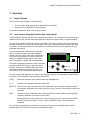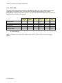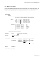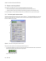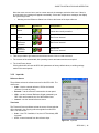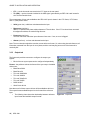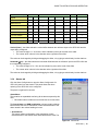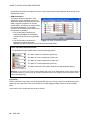
1
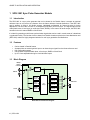
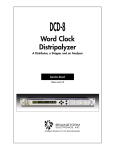
DENSITÉ series SPG-1801 Sync Pulse Generator Module Guide to Installation and Operation M845-9800-100 13 Jul 2007 Miranda Technologies Inc. 3499 Douglas-B.-Floreani St-Laurent, Québec, Canada H4S 1Y6 Tel. 514-333-1772 Fax. 514-333-9828 www.miranda.com © 2007 Miranda Technologies Inc.. GUIDE TO INSTALLATION AND OPERATION Safety Compliance Information Safety Compliance This equipment complies with: - CSA C22.2 No. 60950-1-03 / Safety of Information Technology Equipment, Including Electrical Business Equipment. UL 60950-1 (1st Edition) / Safety of Information Technology Equipment, Including Electrical Business Equipment. st IEC 60950-1 (1 Edition) / Safety of Information Technology Equipment, Including Electrical Business Equipment. CAUTION These servicing instructions are for use by qualified service personnel only. To reduce the risk of electric shock, do not perform any servicing other than that contained in the operating instructions unless you are qualified to do so. Refer all servicing to qualified service personnel. Servicing should be done in a static-free environment. Electromagnetic Compatibility - This equipment has been tested for verification of compliance with FCC Part 15, Subpart B, class A requirements for Digital Devices. This equipment complies with the requirements of: EN 55022 Class A, Electromagnetic Emissions, EN 61000-3-2 & -3-3, Disturbance in Supply Systems EN 61000-4-2, -3, -4, -5, -6, -8 & -11 Electromagnetic Immunity How to contact us: For technical assistance, please contact the Miranda Technical support centre nearest you: Americas Telephone: +1-800-224-7882 e-mail: [email protected] Asia Telephone: +81-3-5730-2987 e-mail: [email protected] Visit our web site at www.miranda.com SPG-1801 Europe, Middle East, Africa, UK Telephone: +44 (0) 1491 820222 e-mail: [email protected] France (only) Telephone: +33 (0) 1 55 86 87 88 e-mail: [email protected] GUIDE TO INSTALLATION AND OPERATION Table of Contents 1 SPG-1801 Sync Pulse Generator Module.................................................................................4 1.1 1.2 1.3 1.4 1.5 2 Installation ..................................................................................................................................6 2.1 2.2 2.3 3 Unpacking ........................................................................................................................................... 6 Installation in the Densité frame.......................................................................................................... 6 Connection .......................................................................................................................................... 6 Operation ....................................................................................................................................7 3.1 3.2 3.3 4 Introduction ......................................................................................................................................... 4 Features .............................................................................................................................................. 4 Block Diagram..................................................................................................................................... 4 Card Front Edge Layout...................................................................................................................... 5 Application........................................................................................................................................... 5 Control Options ................................................................................................................................... 7 Local control using the Densité frame control panel........................................................................... 7 3.2.1 Status LED ............................................................................................................................. 8 3.2.2 Menu for local control............................................................................................................. 9 Remote control using iControl........................................................................................................... 10 3.3.1 The iControl graphic interface window................................................................................. 10 3.3.2 Input tab ............................................................................................................................... 11 3.3.3 Output tab ............................................................................................................................ 12 3.3.4 Alarms tab ............................................................................................................................ 13 3.3.5 Info tab ................................................................................................................................. 16 Specifications ...........................................................................................................................18 SPG-1801 GUIDE TO INSTALLATION AND OPERATION 1 SPG-1801 Sync Pulse Generator Module 1.1 Introduction The SPG-1801 is a sync pulse generator that can be slotted in the Densité frame. It accepts an external reference input or can receive its reference from the frame reference internal distribution, if the REF-1801 card is present. It offers 2 full flexible outputs, individually configurable for format but also for timing adjustment. The SPG-1801 can lock on a composite (NTSC/PAL) or tri-level sync. The signal output can be video (black burst, tri-level sync) or audio (word clock, DARS). In the case of an audio output, the SPG-1801 can also lock on an external DARS or Word Clock. It is ideal for generating multi-format synchronization signals that can be used in certain areas of a broadcast or production facility. The fact that it can be slotted in a Densité chassis coupled to the frame distribution card (REF-1801) makes it a highly-integrated solution for multi sync generation and distribution. 1.2 Features • • • • • 1.3 Can be slotted in Densité frames Accepts either an external genlock input or an internal sync signal from the frame reference card fully configurable outputs Can generate composite black burst, tri-level sync, DARS or Word Clock Up to 1 frame adjustable timing for each individual output Block Diagram URS4D frame’s reference SPG-1801 Genlock REF IN Black burst generator DARS / Word Clock extractor Color framing extractor Timecode extractor LTC IN Remote Control Tri-Level sync generator SYNC OUT Sync manager Word Clock generator DARS generator MicroController SPG-1801 Functional Bloc Diagram 4 | SPG-1801 1 2 GUIDE TO INSTALLATION AND OPERATION Card Front Edge Layout Select Status 1.4 SPG-1801 SELECT button Status LED 1.5 Application One interesting application of the SPG-1801 combines the URS4D signal that is distributed to all Densité slots within the same frame from an REF-1801 card in slot 10, with multiple dual-independent-output SPG1801 cards to create a multi-format audio/video reference generation system. REF NTSC Black REF-1801 720p Tri-Level URS REF SPG-1801 Multi-Format Sync Generator Module NTSC Black 720p Tri-Level URS NTSC Black REF SPG-1801 Multi-Format Sync Generator Module 1080i Tri-Level URS REF SPG-1801 Multi-Format Sync Generator Module NTSC Black DARS SPG-1801 | 5 GUIDE TO INSTALLATION AND OPERATION 2 Installation 2.1 Unpacking The following items should be included in the SPG-1801 package: • • • 2.2 SPG-1801 Sync Pulse Generator Module SPG-1801-SRP rear panel User manual Installation in the Densité frame The SPG-1801 must be mounted in a DENSITÉ-2 frame. The installation includes both the SPG-1801 module, and the rear panel module. It is not necessary to switch off the frame’s power when installing or removing the card. Detailed instructions for installing cards and their associated rear panels in the Densité frame are given in the Densité Frame manual. 2.3 Connection All connections are made on the rear panel: • Connect the input reference signal to the BNC marked REF A loop-through is provided, which should be terminated if unused. • Connect LTC time-code to the BNC marked LTC IN • Two programmable sync outputs are available on the SYNC OUT BNC connectors Figure 2.1 SPG-1801-SRP rear panel 6 | SPG-1801 GUIDE TO INSTALLATION AND OPERATION 3 Operation 3.1 Control Options The SPG-1801 has two primary control interfaces: • • The local control panel attached to the Densité frame’s controller Remote control using Miranda’s iControl system These will be explained in detail in the following sections. 3.2 Local control using the Densité frame control panel Push the SELECT button on the SPG-1801 card edge (see Section 1.4) to assign the local control panel to operate the SPG-1801. Use the control panel buttons to navigate through the menu, as described below. All of the cards installed in a Densité frame are connected to the frame’s controller card, which handles all interaction between the cards and the outside world. There are no operating controls located on the cards themselves. The controller supports remote operation via its Ethernet ports, and local operation using its integrated control panel. The local control panel is fastened to the controller card by a hinged connector, and when installed is located in the front center of the frame, positioned in front of the power supplies. The panel consists of a display unit capable of displaying two lines of text, each 16 characters in length, and five pushbuttons. CONTROLLER The panel is assigned to operate any card in the frame by pushing the SELECT button on the front edge of that card. Pushing the CONTROLLER button on the control panel selects the Controller card itself. The STATUS LED on the selected card flashes yellow. ESC + - SELECT The local control panel displays a menu that can be navigated using the four pushbuttons located beneath the display. The functionality of the pushbuttons is as follows: [CTRL] Selects the controller card for status monitoring and adjustment [+] [–] Used for menu navigation and value modification [SELECT] Gives access to the next menu level. When a parameter value is shown, pushing this button once enables modification of the value using the [+] and [–] buttons; a second push confirms the new value [ESC] Cancels the effect of parameter value changes that have not been confirmed; pushing [ESC] causes the parameter to revert to its former value. Pushing [ESC] moves the user back up to the previous menu level. At the main menu, [ESC] does not exit the menu system. To exit, re-push the [SELECT] button for the card being controlled. If no controls are operated for 30 seconds, the controller reverts to its normal standby status, and the selected card’s STATUS LED reverts to its normal operating mode. SPG-1801 | 7 GUIDE TO INSTALLATION AND OPERATION 3.2.1 Status LED The status monitor LED is located on the front card-edge of the SPG-1801, and is visible through the front access door of the DENSITÉ frame. This multi-color LED indicates module status by color, and by flashing/steady illumination, according to the chart. The chart also indicates fault reporting for this card on the DENSITÉ frame’s serial and GPI interfaces. Serial Report Mode Freerun GPI Report Green Yellow No Time Code Hardware failure Flashing Red No Signal I/O Mismatch Red : Factory default. NOTE: A “Flashing Yellow” Status LED indicates that the SELECT button on the front panel has been pushed. 8 | SPG-1801 GUIDE TO INSTALLATION AND OPERATION 3.2.2 Menu for local control The SPG-1801 has operating parameters which may be adjusted locally at the controller card interface. After pressing the SELECT button on the SPG-1801 module, use the keys on the local control panel (described above) to step through the displayed menu and adjust the parameters. The menu is shown below. STATUS OUTPUT CONFIG OUTPUT 1 OUPUT FORMAT : OFF/ BLACK B. 59.94 / BLACK B. 50 / Tri-L 1080i59.94 / Tri-L 1080i50 / Tri-L 720p59.94 / Tri-L 720p50 / DARS 48 kHz / WORD CLOCK 48 kHz VERTICAL [-524, …. -2, -1, 0, 1, 2, …. 523, 524] (lines) (525) [-624, …. -2, -1, 0, 1, 2, …. 523, 624] (lines) (625) [-1124, ….-2, -1, 0, 1, 2, …, 1123, 1124] (lines) (1080i) [-749, …. -2, -1, 0, 1, 2, …, 748, 749] (lines) (720p) HORIZONTAL [0, 0.037, 0.064, …. 63,5] (us) (525) [0, 0.037, 0.064, …. 64] (625) (us) [0, 0.013, 0.027, …. 29.67] (us) (1080i59.94) [0, 0.013, 0.027, …. 35.56] (us) (1080i50) [0, 0.013, 0.027, …. 22.24] (us) (720p59.94) [0, 0.013, 0.027, …. 26.67] (us) (720p50) OUTPUT 2 (Same sub-menu as for OUTPUT 1) REFERENCE TIME CODE CONFIG ALARMS SOURCE [AUTO, EXTERNAL, URS, INTERNAL] [AUTO, LTC, VITC, URS] NO INPUT SIGNAL NO TIME CODE I/O MISMATCH VERSION SPG-1801: xxx FACTORY DEFAULT [RESTORE] ALARM LEVEL [GREEN, YELLOW, RED, FLASH RED] ALARM REPORT [NONE, GPI] ALARM LEVEL [GREEN, YELLOW, RED, FLASH RED] ALARM REPORT [NONE, GPI] ALARM LEVEL [GREEN, YELLOW, RED, FLASH RED] ALARM REPORT [NONE, GPI] SPG-1801 | 9 GUIDE TO INSTALLATION AND OPERATION 3.3 Remote control using iControl The operation of the SPG-1801 may be controlled using Miranda’s iControl system. • This manual describes the control panels associated with the SPG-1801 and their use. • Please consult the iControl User’s Guide for information about setting up and operating iControl. In iControl Navigator or iControl Websites, double-click on the SPG-1801 icon to open the control panel. 3.3.1 The iControl graphic interface window The basic window structure for the SPG-1801 is shown in figure 3.1. The window identification line at the top gives the card type (SPG-1801), and the slot number in which the card is installed in the Densité frame. On the left is a Status icon for the card. 1 2 3 4 Figure 3.1 SPG-1801 iControl graphic interface window There are four main sections in the window itself, identified in figure 3.1: 1. The top section displays icons on the left. These icons report card communication status, input reference signal format and status, and output reference signal status. Icon # 1 10 | SPG-1801 2 3 4 GUIDE TO INSTALLATION AND OPERATION Move the cursor over an icon to see its current status in the message area below the icons. If there is an error status, the message will appear automatically. If there are multiple error messages, the display will cycle through them • Icon # Mousing over the Reference Status icon will show the format of the input reference Indicates appearance interpretation 1 Card control status Green if the card is controlled remotely Yellow when locally controlled 2 Input Reference status Green if OK, Red if error detected 3 Output 1 Reference mismatch Green if OK, Red if error detected 4 Output 1 Reference mismatch Green if OK, Red if error detected 2. Tabs are provided to give access to the various controls. Click on a tab to access it 3. The contents of the selected tab, with operating controls and status monitors as required. 4. The Load Factory button. Clicking this button will reset all SPG-1801 parameters to factory-default values, overriding settings made in the control panels. 3.3.2 Input tab Reference Source The pulldown selects the reference source for this SPG-1801. The choices are: • Auto – Use the external reference, URS or the internal reference (in order of priority). • External – use the reference connected to the rear panel • URS – use the Universal Reference Signal generated by an REF-1801 card located in slot 10 of the Densité frame • Internal – use the internal reference source Time Code The Timecode Source pulldown selects the source of timecode that will be inserted in the outgoing reference signals from this SPG1801. The choices are: • Auto – Use LTC if available, if not, then VITC and lastly URS timecode. • VITC – extract timecode from the reference input Figure 3.2 Input tab SPG-1801 | 11 GUIDE TO INSTALLATION AND OPERATION • LTC – use the timecode connected to the LTC input on the rear panel • TC (URS) – use the timecode included in the URS signal. generated by an REF-1801 card located in slot 10 of the Densité frame The current status of time code available at the SPG-1801 input is shown in the LTC Status, VITC Status and TC (URS) Status areas • Valid (green icon): valid time code detected at the input • Phase error (red icon): SMPTE-12 specifies the phase relation between LTC and video. If the LTC received does not match this alignment window, the card will flag this error. • Frame error (red icon): The time code must match the input reference frame rate. If not, an error is flagged. • Absent (red icon): no time code detected at the input Note: The error detection algorithm uses the current reference format. So, when using internal reference, all information extracted from the input is out of phase, and the card may flag errors even if the timecode is nominally OK. 3.3.3 Output tab The Output tab provides resources to configure the output sync signals. • Each of the two sync outputs can be configured independently. Format – the pulldown selects the format of the sync output. Available choices are: • Black Burst 59.94 • Black Burst 50 • Tri-Level 1080i59.94 • Tri-Level 1080i50 • Tri-Level 720p59.94 • Tri-Level 720p50 • DARS 48 kHz • Word Clock 48 kHz Note that not all of these output choices will be available at all times. The output formats available depend on the format of the reference input. • The following chart shows the relationship between reference input format and available output formats. 12 | SPG-1801 Figure 3.3 Output tab GUIDE TO INSTALLATION AND OPERATION DAR Word Clock 48 KHz 48 KHz • • • • • • • • • • • • DARS 48 kHz • • Word Clock 48 kHz • • Output Black Burst 59.94 Input Black Burst 59.94 50 • 1080i50 720p59.94 • • • • • • • Tri-Level 720p50 720p50 • • Tri-Level 1080i50 Tri-Level 720p59.94 1080i59.94 • Black Burst 50 Tri-Level 1080i59.94 Tri-Level • • • Vertical (lines) – the slider selects the vertical offset between the reference input to the SPG-1801 and the output being configured. • The nominal range is +/- one frame, and is indicated (in lines) at the ends of the slider • The current value is shown in the data box at the right side of the slider. The value can be changed by clicking and dragging the slider, or by typing a value directly into the data box. Horizontal (μsec) – the slider selects the horizontal offset between the reference input to the SPG-1801 and the output being configured. • The nominal range is 0 to 1 line, and is indicated (in μsec) at the ends of the slider • The current value is shown in the data box at the right side of the slider. The value can be changed by clicking and dragging the slider, or by typing a value directly into the data box. 3.3.4 Alarms tab Click the Alarm Config button to open the Alarm Configuration for SPG-1801 panel in a new window. This panel allows the alarm reporting of the SPG-1801 to be configured. The panel is organized in columns. Status/Name This contains an expandable tree listing all the alarms reported by this card. • Each alarm name includes an icon that shows its current status The Overall alarm and GSM contribution columns contain pulldown lists that allow the level of contribution of each individual alarm to the alarm named in the column heading to be set. • Overall Alarm This column allows configuration of the contribution of each individual alarm to the Overall Alarm associated with this card. The Figure 3.4 Alarms tab SPG-1801 | 13 GUIDE TO INSTALLATION AND OPERATION Overall Alarm is shown in the upper left corner of the iControl panel, and also appears at the bottom of the Status/Name column. • GSM Contribution This column allows configuration of the contribution of each individual alarm to the GSM Alarm Status associated with this card. GSM is a dynamic register of all iControl system alarms, and is also an alarm provider for external applications. The possible values for this contribution are related to the Overall alarm contribution: • If the Overall alarm contribution is selected as Disabled, the GSM alarm contribution can be set to any available value • If the Overall alarm contribution is Figure 3.5 Alarm Configuration panel selected as any level other than disabled, the GSM contribution is forced to follow the Overall Alarm. Levels associated with these alarms: The pulldown lists may contain some or all of the following options: The alarm makes no contribution (black icon) The alarm is of minor importance (yellow icon) The alarm is of major importance (orange icon) The alarm is of critical importance (red icon) The alarm exists but has no effect (used for text and composite alarms) Shortcut: if you click in one of the columns beside SPG-1801 in the Status/Name column (where there is no pulldown shown), you will open an “invisible” pulldown that lets you assign a level to all alarms in that column simultaneously. Log Events iControl maintains a log of alarm events associated with the card. The log is useful for troubleshooting and identifying event sequences. Click in the checkbox to enable logging of alarm events for each individual alarm. At the bottom of the window are several other controls 14 | SPG-1801 GUIDE TO INSTALLATION AND OPERATION Copy to other cards Click this button to open a panel that allows the alarm configuration set for this card to be copied into another SPG-1801 card. • Select one or more destination cards from the list in the window by clicking in the checkboxes, or all of them by clicking in the All checkbox Figure 3.6 Copy to other cards window Get alarm keys Click this button to open a save dialog where you can save a file containing a list of all alarms on this card and their current values, along with an Alarm Key for each. The alarm keys are useful for system integration and troubleshooting. • The file is saved in Excel.csv format Figure 3.7 Get alarm keys save dialogue OK, Apply, Cancel • OK accepts the settings and closes the window once the card confirms that there are no errors. • Apply accepts the settings, but leaves the window open • Cancel closes the window without applying any changes, and leaves the previous settings intact. SPG-1801 | 15 GUIDE TO INSTALLATION AND OPERATION 3.3.5 Info tab When the SPG-1801 is included in an iControl environment, certain information about the card should be available to the iControl system. The user can enter labels and comments that will make this card easy to identify in a complex setup. This information is entered into data boxes in the Info control panel. Label: type the label that appear for this card when it appears in iControl applications Short Label type the short-form label that iControl uses in some cases (8 characters) Source ID type a descriptive name for this card Comments: type any desired text The remaining data boxes show manufacturing information about this card. Figure 3.8 Info tab Three buttons in the panel give access to other information. • Details…: Reports the Firmware version, service version, and panel version for this card Figure 3.9 Details window • Advanced…: Shows the Miranda LongID for this card. The Miranda LongID is the address of this SPG-1801in the iControl network. Figure 3.10 Advanced window 16 | SPG-1801 GUIDE TO INSTALLATION AND OPERATION • Remote System Administration – opens the Joining Locators window, which lists remote lookup services to which this SPG-1801 is registered. Add: Force the iControl service for this SPG-1801 to register itself on a user-specified Jini lookup service, using the following syntax for the locator’s URL in the Input data box: jini://<ip_address> where <ïp_address> is the ip address of the server running the lookup service, e.g. Figure 3.11 Joining Locators window Remove: select one of the services listed in the window by clicking on it, and click Remove to delete it from the window SPG-1801 | 17 GUIDE TO INSTALLATION AND OPERATION 4 Specifications GENLOCK INPUT CONNECTOR BNC per IEC 60169-8 Amendment 2 LOAD Passive Loop-Through IMPEDANCE 75 Ohm bridging RETURN LOSS > 30dB up to 30MHz FREQUENCY LOCK RANGE compliant with RS-170M SNR > 40dB SIGNAL TYPE Composite NTSC-M, PAL-B Black Burst with optional VITC STANDARD SMPTE-170M, ITU-R BT.1700-1, SMPTE-318M SIGNAL LEVEL 1V p-p SIGNAL TYPE HD Tri-Level Sync STANDARD SMPTE-274M, SMPTE-296M SIGNAL LEVEL 600mV p-p SIGNAL TYPE DARS AES-3id STANDARD SMPTE-276M SIGNAL LEVEL 1V p-p SIGNAL TYPE Word Clock STANDARD AES11-2003 SIGNAL LEVEL 2.0V p-p ANALOG REFERENCE OUTPUT SIGNAL TYPE Composite NTSC-M, PAL-B with optional VITC STANDARD SMPTE-170M, ITU-R BT.1700-1, SMPTE-318M SIGNAL LEVEL 1V p-p RETURN LOSS > 35dB up to 10MHz SIGNAL TYPE HD Tri-Level Sync STANDARD SMPTE-274M, SMPTE-296M SIGNAL LEVEL 600mV p-p 18 | SPG-1801 GUIDE TO INSTALLATION AND OPERATION SIGNAL TYPE DARS AES-3id STANDARD SMPTE-276M SIGNAL LEVEL 1V p-p SIGNAL TYPE Word Clock STANDARD AES11-2003 SIGNAL LEVEL 2.0V p-p OTHER MAXIMUM POWER PHYSICAL FORMAT 5W Densité-2 SPG-1801 | 19