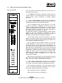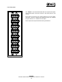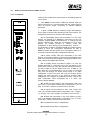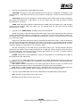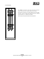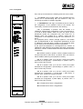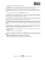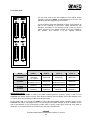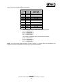
1
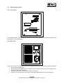
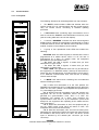
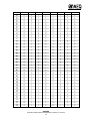
RANGER
Data and Audio Channel Multiplexer with
E1/T1 Access
USER’S MANUAL
ED. 02/02
A.E.Q., S.A., manufacturer of this equipment, is a “Registered Company”by
AENOR with reg. no. ER-080/1/96, in accordance with UNE standard EN-ISO-9001
INDEX
1
GENERAL REMARKS .................................................................................................................... 3
1.1 General precautions ....................................................................................................... 3
1.1.1 Read all the instructions................................................................................ 3
1.1.2 Connections to power supply and ground ................................................... 3
1.1.3 Protection against voltage fluctuations........................................................ 3
1.1.4 Protection from water and humidity.............................................................. 3
1.1.5 Ventilation, fire and flammable vapors ......................................................... 3
1.1.6 Maintenance................................................................................................... 3
2
DESCRIPTION OF THE EQUIPMENT............................................................................................. 4
2.1 General description of the equipment ........................................................................... 4
2.2 Brief description of the modules.................................................................................... 4
3
DESCRIPTION OF THE MODULES................................................................................................ 5
3.1 Modular rack ................................................................................................................... 5
3.2 Power supply module..................................................................................................... 6
3.2.1 Front panel ..................................................................................................... 6
3.2.2 Rear panel ...................................................................................................... 6
3.3 Control module ............................................................................................................... 7
3.3.1 Front panel ..................................................................................................... 7
3.3.2 Rear panel .....................................................................................................12
3.3.3 Equipment interconnection ..........................................................................13
3.3.4 Jumper configuration ...................................................................................14
3.4 Audio I/O module with eight 4B/8C circuits..................................................................16
3.4.1 Front Panel....................................................................................................16
3.4.2 Rear panel .....................................................................................................18
3.5 Audio I/O module with four 4B/4C circuits ...................................................................19
3.5.1 Front panel ....................................................................................................19
3.5.2 Rear panel .....................................................................................................21
3.6 Data module...................................................................................................................22
3.6.1 Front panel ....................................................................................................23
3.6.2 Rear panel .....................................................................................................25
3.6.3 Pin-out of the V35 interface connectors ......................................................26
4
TECHNICAL SPECIFICATIONS ....................................................................................................27
5
SOFTWARE...................................................................................................................................29
5.1 Introduction....................................................................................................................29
5.2 Minimum installation requirements ..............................................................................29
5.3 RANGER Engineering Planning ....................................................................................30
5.4 RANGER Realtime Control ............................................................................................36
5.5 RANGER Firmware Upgrade .........................................................................................46
RANGER
Data and Audio Channel Multiplexer with E1/T1 Access
2
1 GENERAL REMARKS
1.1
General precautions
The security measures and precautions described below must be observed in all phases of operation and
maintenance of this unit. Failing to respect the indications that are emphasized in this section may alter
the operation and features of the RANGER as the result of improper use of the equipment.
1.1.1 Read all the instructions
It is absolutely essential to read carefully all the instructions set forth in this manual, and to read them in
the established order, before connecting the equipment to the mains power supply and starting it up.
In this way, you will get the best possible performance out of the multiplexer from the outset and, at the
same time, you will be able to avoid incorrect or improper operations that could damage it.
1.1.2 Connections to power supply and ground
To reduce the risk of electric shocks, the power supply or supplies that feed this unit must be grounded.
The RANGER is supplied with a lateral ground connection plug. If this plug should ever need to be
replaced, it should be borne in mind that the ground wire has green and yellow color coding on its
insulation.
1.1.3 Protection against voltage fluctuations
In geographic areas where voltage fluctuations in electric lines are frequent, it will be necessary to add
external protection to the multiplexer to ensure that the voltage it receives is the same voltage specified in
this manual.
1.1.4 Protection from water and humidity
We recommend against using the RANGER in areas where it may be subjected to splashing, rain, etc., or
in places with damp floors. Its use should also be avoided in places having a high degree of atmospheric
humidity, which frequently condenses on equipment.
1.1.5 Ventilation, fire and flammable vapors
The multiplexer must never be placed near or on a heat source. The use of electric or electronic
equipment near fire or in an atmosphere that is permeated with flammable vapors is highly dangerous,
and must be avoided at all costs.
All the ventilation grilles must be kept uncovered to ensure proper air circulation and to allow hot air to be
exhausted from the equipment.
1.1.6 Maintenance
Only qualified service technicians should be allowed to perform maintenance operations on the RANGER.
AEQ, S.A. is not responsible for any damage caused to the multiplexer by unauthorized maintenance
operations on the equipment, nor for any damages that a RANGER subjected to unauthorized repair may
cause to other equipment items or persons.
Always bear in mind that there are very high voltages inside the power supply. They can cause severe
electric shocks. Therefore, proceed with the greatest caution when handling this unit.
RANGER
Data and Audio Channel Multiplexer with E1/T1 Access
3
2 DESCRIPTION OF THE EQUIPMENT
2.1
General description of the equipment
The RANGER is a coded data and audio channel multiplexer with E1 (2,048 Mbps) and T1 (1,544 Mbps)
access.
It enables its users to work with codified audio quality levels of 3.5 kHz, 7.5 KHz, and 15 kHz bandwidth,
and with data channels of 256 Kbps, 128 Kbps and 64 Kbps bandwidth. When connected to an E1 type
access (32 64-Kbps slots), it can use 31 64-Kbps slots for audio and transmission and the remaining 64Kbps channel for synchronization, and when connected to a T1 access, it can use 24 64-Kbits slots.
The RANGER is built on a standardized 19-inch, 6 units rack with a depth of 360 mm, and offers space
for eight data an daudio I/O modules, one control module and two power supply modules.
2.2
Brief description of the modules
The power supply module is of the switched type. It accepts input voltages in a range of 85-132/170-264
V AC 50/60 Hz, and puts out 48 V DC with a maximum power of 150W.
The control module is where the digital E1 or T1 access connection is made through a twisted pair (a
future option will allow optical fiber to be used), and where the cited accesses are managed. The
multiplexer allows remote control and monitoring functions that include supervision of alarms and of the
status of the modules, as well as the updating of firmware from a remote PC. To make these control
functions possible, this board has a control bus that implements EIA recommendation RS-232, and a RS422 control bus which enables it to be connected to multipoint networks.
The audio I/O module can be of two types, offering up to four 4B/4C audio circuits and a maximum of
eight 4B/8C audio circuits. Each audio I/O module processes four 64-Kbps slots (256 Kbps). As many as
eight I/O modules of any type can be inserted in a RANGER rack.
The 4B/4C type audio module offers three configuration options, depending on the number of audio
circuits and their quality:
1) Two 15 kHz audio circuits.
2) Four 7.5 kHz audio circuits.
3) Two 7.5 kHz audio circuits + one 15 kHz audio circuit.
The 4B/8C type audio module offers three configuration possibilities, according to the number of audio
circuits and their quality:
1) Four 7.5 kHz audio circuits.
2) Four 3.5 kHz audio circuits + two 7.5 kHz audio circuits.
3) Eight 3.5 kHz audio circuits.
The data module offers four different configurations:
1) One 256 Kbps data circuit.
2) Two 128 Kbps data circuits.
3) One 128 Kbps data circuit + two 64 Kbps data circuits.
4) Four 64 Kbps data circuits.
Up to six data modules in T1 access mode, and up to seven data modules in E1 mode can be inserted in
a RANGER rack.
RANGER
Data and Audio Channel Multiplexer with E1/T1 Access
4
3 DESCRIPTION OF THE MODULES
3.1
Modular rack
©
©
Standardized 19-inch rack, 6 units high and 360 mm deep, of metal construction and providing space for
eight data and audio I/O modules, one control module and two power supply modules. The ventilation of
the electronic components is ensured by ventilation slots at the top and bottom of the rack, and by the
power supply ventilation fans.
-
+
-
+
-
+
- +
-
+
-
+
-
+
-
+
-
+ -
+
+
RANGER
Data and Audio Channel Multiplexer with E1/T1 Access
5
+
-
+
-
+
3.2
Power supply module
3.2.1 Front panel
©
This module features a DC ON indicator that lights up when the equipment is powered up and the back
panel switch is in the ON position.
3.2.2 Rear panel
From top to bottom, the following elements can be distinguished on the power supply module back panel:
• Off / on switch labeled “ON”
• DC ON indicator that lights when the indicator is powered up and the switch is in the ON position.
• Fuse block with 6-Ampere fuses
• IEC type connector for connecting the cable to the mains
• Also found on the back panel is the hot air outlet grille associated with the power supply fan.
RANGER
Data and Audio Channel Multiplexer with E1/T1 Access
6
3.3
Control module
3.3.1 Front panel
The following elements can be distinguished from top to bottom:
• Two RX/TX communications LEDs that indicate when the
remote control PC is in communication with the control board to
carry out remote control, monitoring or software updating
processes.
• A DIP switch block containing eight microswitches: this is
used to convert the RANGER rack identification into binary code
(see the coding table at the end of this chapter).
• A numeric “ADDRESS” indicator with three seven-segment
displays which indicate the identification programmed by means
of the DIP switches, that is, the address of the node that a control
module occupies in the multipoint control network.
• A group of four operational mode LEDs that indicate the
following:
- MASTER. When this LED is lighted, it means that the rack is
programmed as a master device; when it is off, the rack is
programmed as a slave. (In master mode, the equipment
generates the synchronization clock.)
- E1. When this LED is lighted, it means that you have
selected the E1 type access.
- T1. When this LED is lighted, it means that you have
selected the T1 type access.
- TEST LOOP. This operational mode can only be used when
the equipment is in MASTER mode; it sets up an internal E1/T1
frame loop and, simultaneously, an external loop involving the E1
or T1 balanced communication lines, with the aim of creating
remote external loops.
• A “MODE” DIP switch block containing four microswitches
with the following functions:
- Nr. 1: When this microswitch is in the “ON” position, the
RANGER will operate with an E1 (2,048 Mbps) access. When the
switch is in the “OFF” position, the multiplexer will operate with a
T1 (1,544 Mbps) type access.
- Nr. 2: With this second microswitch in the “ON” position, the
equipment will act as the “MASTER” device and thus will
generate the synchronization clock; when it is “OFF” the
multiplexer will operate as a slave, thus receiving the
synchronization clock sent to it by the MASTER. (There must
always be one equipment item operating as the master and the
other as its slave).
- Nr. 3: When this microswitch is “ON,” the equipment will go
into the “TEST LOOP” mode. When the switch is “OFF,” the
multiplexer will not execute this function.
- Nr. 4: With this microswitch “ON,” the E1/T1 access input is
selected by the optical fiber TX/RX connectors (an option that will
be available in the future). When it is “OFF,” the E1/T1 access
input is selected by the twisted pair connector (an RJ-45
connector)..
RANGER
Data and Audio Channel Multiplexer with E1/T1 Access
7
•
Group of nine alarm LEDs that indicate the following:
- LINE FAILURE. Line failure alarm.
The G703 output driver is protected against power surges in order to prevent damage to the output
transformer. If a high level is not detected during 192 transmission clock cycles, an alarm is generated
that persists until a high level appears in the line.
If the line failure LED lights up when no other equipment item is connected to its end, it means that there
is a short circuit in the transmission line. When it is confronted with another equipment item and this LED
is lighted, it means that the driver is limiting the current that it generates through the line and that,
therefore, STRAPS L0, L1 and L2 need to be configured. When these straps are in their peak position
they are configured to generate the maximum current and thus to reach the greatest length.
- CARRIER LOSS. Absence of carrier.
This LED comes on after 32 consecutive zeros in reception, and returns to its normal status with the next
“1”received.
- SINC.LOSS. Lack of synchronization.
Indicates that the transceiver cannot synchronize with the incoming frames.
- FRAME ERROR. Frame alarm.
This alarm is generated when an erroneous code is received in the frame alignment.
- M.FRAME ALARM. Multiframe alarm.
This LED is lighted when a loss of the multiframe alignment is detected.
- REMOTE ALARM.
Generated when the remote alarm bit is activated.
- SERVICE ALARM.
This alarm is generated when the RANGER is out of service. The presence of the alarm implies that there
is no communication with the other node. It can be generated either by loss of synchronization, loss of
carrier or by a frame alignment error. When this alarm is generated, the maintenance alarm will always be
generated simultaneously so that an immediate check of the system will be made.
- MAIN. ALARM. Maintenance alarm.
This alarm is generated whenever a service alarm exists, or when a remote or multiframe alarm is
received. It tells you that the communication is satisfactory and that the problem is being generated at the
other end of the network, which means that the other end needs to be checked or serviced.
- AUDIO FAILURE. Audio board failure alarm.
This alarm LED is activated when one of the audio boards connected to the system is operating
incorrectly or not at all.
RANGER
Data and Audio Channel Multiplexer with E1/T1 Access
8
ADDRESS
SW-1
SW-2
SW-3
SW-4
SW-5
SW-6
SW-7
SW-8
0
1
2
3
4
5
6
7
8
9
10
11
12
13
14
15
16
17
18
19
20
21
22
23
24
25
26
27
28
29
30
31
32
33
34
35
36
37
38
39
40
41
42
43
44
45
46
47
48
49
50
51
52
53
54
55
56
57
58
59
0
0
0
0
0
0
0
0
0
0
0
0
0
0
0
0
0
0
0
0
0
0
0
0
0
0
0
0
0
0
0
0
0
0
0
0
0
0
0
0
0
0
0
0
0
0
0
0
0
0
0
0
0
0
0
0
0
0
0
0
0
0
0
0
0
0
0
0
0
0
0
0
0
0
0
0
0
0
0
0
0
0
0
0
0
0
0
0
0
0
0
0
0
0
0
0
0
0
0
0
0
0
0
0
0
0
0
0
0
0
0
0
0
0
0
0
0
0
0
0
0
0
0
0
0
0
0
0
0
0
0
0
0
0
0
0
0
0
0
0
0
0
0
0
0
0
0
0
0
0
0
0
1
1
1
1
1
1
1
1
1
1
1
1
1
1
1
1
1
1
1
1
1
1
1
1
1
1
1
1
0
0
0
0
0
0
0
0
0
0
0
0
0
0
0
0
1
1
1
1
1
1
1
1
1
1
1
1
1
1
1
1
0
0
0
0
0
0
0
0
0
0
0
0
0
0
0
0
1
1
1
1
1
1
1
1
1
1
1
1
0
0
0
0
0
0
0
0
1
1
1
1
1
1
1
1
0
0
0
0
0
0
0
0
1
1
1
1
1
1
1
1
0
0
0
0
0
0
0
0
1
1
1
1
1
1
1
1
0
0
0
0
0
0
0
0
1
1
1
1
0
0
0
0
1
1
1
1
0
0
0
0
1
1
1
1
0
0
0
0
1
1
1
1
0
0
0
0
1
1
1
1
0
0
0
0
1
1
1
1
0
0
0
0
1
1
1
1
0
0
0
0
1
1
1
1
0
0
0
0
0
0
1
1
0
0
1
1
0
0
1
1
0
0
1
1
0
0
1
1
0
0
1
1
0
0
1
1
0
0
1
1
0
0
1
1
0
0
1
1
0
0
1
1
0
0
1
1
0
0
1
1
0
0
1
1
0
0
1
1
0
1
0
1
0
1
0
1
0
1
0
1
0
1
0
1
0
1
0
1
0
1
0
1
0
1
0
1
0
1
0
1
0
1
0
1
0
1
0
1
0
1
0
1
0
1
0
1
0
1
0
1
0
1
0
1
0
1
0
1
RANGER
Data and Audio Channel Multiplexer with E1/T1 Access
9
ADDRESS
SW-1
SW-2
SW-3
SW-4
SW-5
SW-6
SW-7
SW-8
60
61
62
63
64
65
66
67
68
69
70
71
72
73
74
75
76
77
78
79
80
81
82
83
84
85
86
87
88
89
90
91
92
93
94
95
96
97
98
99
100
101
102
103
104
105
106
107
108
109
110
111
112
113
114
115
116
117
118
119
0
0
0
0
0
0
0
0
0
0
0
0
0
0
0
0
0
0
0
0
0
0
0
0
0
0
0
0
0
0
0
0
0
0
0
0
0
0
0
0
0
0
0
0
0
0
0
0
0
0
0
0
0
0
0
0
0
0
0
0
0
0
0
0
1
1
1
1
1
1
1
1
1
1
1
1
1
1
1
1
1
1
1
1
1
1
1
1
1
1
1
1
1
1
1
1
1
1
1
1
1
1
1
1
1
1
1
1
1
1
1
1
1
1
1
1
1
1
1
1
1
1
1
1
0
0
0
0
0
0
0
0
0
0
0
0
0
0
0
0
0
0
0
0
0
0
0
0
0
0
0
0
0
0
0
0
1
1
1
1
1
1
1
1
1
1
1
1
1
1
1
1
1
1
1
1
1
1
1
1
1
1
1
1
0
0
0
0
0
0
0
0
0
0
0
0
0
0
0
0
1
1
1
1
1
1
1
1
1
1
1
1
1
1
1
1
0
0
0
0
0
0
0
0
0
0
0
0
0
0
0
0
1
1
1
1
1
1
1
1
1
1
1
1
0
0
0
0
0
0
0
0
1
1
1
1
1
1
1
1
0
0
0
0
0
0
0
0
1
1
1
1
1
1
1
1
0
0
0
0
0
0
0
0
1
1
1
1
1
1
1
1
0
0
0
0
0
0
0
0
1
1
1
1
0
0
0
0
1
1
1
1
0
0
0
0
1
1
1
1
0
0
0
0
1
1
1
1
0
0
0
0
1
1
1
1
0
0
0
0
1
1
1
1
0
0
0
0
1
1
1
1
0
0
0
0
1
1
1
1
0
0
1
1
0
0
1
1
0
0
1
1
0
0
1
1
0
0
1
1
0
0
1
1
0
0
1
1
0
0
1
1
0
0
1
1
0
0
1
1
0
0
1
1
0
0
1
1
0
0
1
1
0
0
1
1
0
0
1
1
0
1
0
1
0
1
0
1
0
1
0
1
0
1
0
1
0
1
0
1
0
1
0
1
0
1
0
1
0
1
0
1
0
1
0
1
0
1
0
1
0
1
0
1
0
1
0
1
0
1
0
1
0
1
0
1
0
1
0
1
RANGER
Data and Audio Channel Multiplexer with E1/T1 Access
10
ADDRESS
SW-1
SW-2
SW-3
SW-4
SW-5
SW-6
SW-7
SW-8
120
121
122
123
124
125
126
127
0
0
0
0
0
0
0
0
1
1
1
1
1
1
1
1
1
1
1
1
1
1
1
1
1
1
1
1
1
1
1
1
1
1
1
1
1
1
1
1
0
0
0
0
1
1
1
1
0
0
1
1
0
0
1
1
0
1
0
1
0
1
0
1
RANGER
Data and Audio Channel Multiplexer with E1/T1 Access
11
3.3.2 Rear panel
You will find the following elements on the back panel:
”ALARMS”section:
An 11-contact Hartmann type pin header connector for external
alarm synchronization. This involves outputs through relays that
are closed when any of the alarms described in the previous
point are detected, plus the “POW.SUPPLY” output, which is
activated when there is a failure in one of the power supplies.
The outputs allow a maximum voltage of 50 V and a maximum
current of 500 mA.
“RS-422 CONTROL PORT”section:
A four pole Hartmann type pin header connector for the Tx and
Rx (“+” y “–“) connection of the RS-422 external multipoint line
for interconnection with other RANGER racks. When two or
more RANGER racks are connected to an RS-422 bus, the
polarity between the connectors must be respected.
+
+
”E1/T1 INTERFACE”section:
An RJ-45 connector for connecting the balanced TX and RX
data access pairs. The physical support is twisted pair cable and
the guaranteed maximum range is 300 m. The pin assignments
are as follows:
- Pair nr. 1 = RX+ pin 1 and RX- pin 2.
- Pair nr. 2 = TX+ pin 7 and TX- pin 8.
“RS-232 CONTROL PORT”section:
A nine contact DB 9 socket (female) connector for connection of
a control PC. The cable should have the following pin-out:
SIGNAL
RANGER
PC
TX
RX
GND
RTS
DB 9 male
2
3
5
7
DB 9 female
2
3
5
7
RANGER
Data and Audio Channel Multiplexer with E1/T1 Access
12
3.3.3 Equipment interconnection
RS-232
-
+
-
+
RS-422
RS-422
RS-422
When several RANGERs are going to be interconnected, it should be done through the RS-422 interface,
pin to pin, respecting the polarity between the connectors of all racks. The control PC is connected to a
single RANGER rack, linking the PC’s serial port COM1 with the RANGER’s RS-232 interface.
-
+
-
+
-
+
+
+
+
+
+
RANGER 1
RANGER 2
RANGER N
PC
CONTROL
COM1
RS-232
RANGER
Data and Audio Channel Multiplexer with E1/T1 Access
13
+
-
+
3.3.4 Jumper configuration
The controller board features twelve programming jumpers. Their function in both access types (E1 and
T1) is the following:
• PT1: Board ground reference selection.
GND
CHASSIS
E1
T1
Board ground isolated from
equipment chassis
Board ground connected to
equipment chassis
Board ground isolated from
equipment chassis
Board ground connected to
equipment chassis
• PT2: Determines the communication port speed (future feature).
E1
T1
NO DOT
19,200 baud
19,200 baud
DOT
38,400 baud
38,400 baud
• PT3: Line code selection in T1 mode.
E1
T1
NO DOT
Not defined (HDB3)
B8ZS
DOT
Not defined (HDB3)
AMI
• PT4: Activation / deactivation of CRC4 multiframe in E1 mode.
E1
T1
NO DOT
CRC4 multiframe activated
Not defined
DOT
CRC4 multiframe deactivated
Not defined
• PT5: Framing selection in T1 mode.
E1
T1
NO DOT
Not defined
193S (12 frames/multiframe)
DOT
Not defined
193E (24 frames/multiframe)
RANGER
Data and Audio Channel Multiplexer with E1/T1 Access
14
• PT6: RESET generation. This jumper is used only for debugging of the board, therefore in normal
operation it has to be always in NO DOT position.
E1
T1
NO DOT
Normal operation
Normal operation
PUNTO
Forbidden configuration
Forbidden configuration
• PT7: Line code selection at driver level. Since the line code selection should be done at
transceiver level with PT3, this jumper should always be configured in NO DOT position
(transparent).
E1
T1
NO DOT
Normal operation
Normal operation
DOT
Forbidden configuration
Forbidden configuration
• PT8/PT9/PT10: Selection of output pulse waveform at the transmitter for T1 mode. It is
recommended to set the three jumpers in DOT position for getting the maximum length.
PT8
PT9
PT10
E1
T1
NO DOT
DOT
NO DOT
DOT
NO DOT
DOT
NO DOT
DOT
NO DOT
NO DOT
DOT
DOT
NO DOT
NO DOT
DOT
DOT
NO DOT
NO DOT
NO DOT
NO DOT
DOT
DOT
DOT
DOT
Not defined
Not defined
Not defined
Not defined
Not defined
Not defined
Not defined
Not defined
Test mode (do not use)
-7,5 dB T1 CSU
-15 dB T1 CSU
0 dB, 0-44 m T1 CSU, DSX-1
44-88 m T1 DSX-1
88-132 m T1 DSX-1
132-176 m T1 DSX-1
176-216 m T1 DSX-1
• PT11/PT12: Selection of reception line impedance for E1 and T1.
PT11
PT12
E1
T1
120
120
120 Ω (twisted pair)
Forbidden configuration
100
120
Forbidden configuration
Forbidden configuration
120
100
Forbidden configuration
Forbidden configuration
100
100
Forbidden configuration
100 Ω
RANGER
Data and Audio Channel Multiplexer with E1/T1 Access
15
3.4
Audio I/O module with eight 4B/8C circuits
3.4.1 Front Panel
From top to bottom, the following elements can be found on the
front panel of this module:
• Two RX/TX communication LEDs that indicate when the
remote control PC is communicating with the audio board to
execute remote control, monitoring or software updating
processes.
• A block of DIP switches containing eight microswitches.
This is used to configure the operating mode of the module. The
configurations that can be set up are the following:
- Nr. 1 (LOC/REM): When this microswitch is in the “ON”
position, the module is in “REMOTE” mode and you can only
configure “AUDIO MODE” microswitches 3, 4, 5 and 6 from the
remote controlling PC. When the switch is in the “OFF”position,
the module functions in “LOCAL” mode, and configuration is
done directly from microswitches 3, 4, 5 and 6.
The equipment includes a FLASH-EPROM non-volatile memory
system to store the configuration parameters so that, in
REMOTE mode and after power-up, the equipment starts up in
accordance with the last audio configuration selected.
- Nr. 2 (TEST LOOP): With this microswitch in the “ON”
position, the module makes a local loop at the 256-Kbps frame
level of the audio circuits it manages. Changing this switch to the
“OFF”position will disable this function.
- Nr. 3 (TONE): When microswitch number 3 is “ON,” the
module generates a 1 kHz test tone in all the outputs of the
active audio circuits. By using the relevant adjustment trimmer,
you will be able to vary the output level from -10 dBU to +10
dBU. When any of microswitches 4, 5 or 6 is “ON,” the tone will
only come out through the active audio circuits. If no audio
configuration is active, the tone will come out through all the
outputs; the same will occur if you select an incorrect audio
configuration (for example, microswitches 4 and 5 “ON”) or any
other combination. When microswitch Nr. 3 is “OFF,” this
function will be disabled.
- Nr. 4: With this microswitch in the “ON” position (and 5 and
6 are “OFF”), the module enables audio configuration 1 (4 x 7.5
kHz). In the “OFF”position, this switch has no function.
- Nr. 5: When this microswitch is “ON,” (and 3 and 6 are
“OFF”), the module enables audio configuration 2 (4 x 3.5 kHz +
2 x 7.5 kHz). In the “OFF”position, this switch has no function.
- Nr. 6: With this microswitch in the “ON” position (4 and 5
“OFF”), the module enables audio configuration 3 (8 x 3.5 kHz).
In the “OFF”position, this switch has no function.
- Nr. 7: Reserved for future configurations.
- Nr. 8: Reserved for future configurations.
RANGER
Data and Audio Channel Multiplexer with E1/T1 Access
16
•
A group of three operating mode LEDs that indicate the following:
- LOC/REM. The lighting of this LED indicates that the module is configured in “REMOTE” mode
(microswitch Nr. 1 ON). When the LED is off, the module is configured in “LOCAL”mode (microswitch Nr.
1 OFF).
- TEST LOOP. When this LED is lighted it indicates that the TEST LOOP mode has been selected for
this module (microswitch Nr. 2 ON). When it is off, the module does not have this function enabled
(microswitch Nr. 2 is OFF).
- TONE. When this LED is lighted it indicates that the TONE mode (microswitch Nr. 3 ON) has been
selected for the module. When the LED is off, the module does not have this function enabled
(microswitch Nr. 3 is OFF).
•
A group of four “AUDIO MODE”operating mode LEDs that announce the following:
- 4 x 7,5. The lighting of this LED tells you that audio mode 1 (four 7.5 kHz channels) has been
selected for the module and that, therefore, microswitch Nr. 4 is ON and 3 and 6 are OFF. When the LED
is off, the module does not have this function enabled (microswitch Nr. 4 is OFF, or another selection
involving 5 or 6 has been made).
- 4 x 3,5 + 2 x 7,5. When this LED is lighted it indicates that audio mode 2 (four 3.5 kHz channels plus
two 7.5 kHz channels) has been selected for the module; microswitch Nr. 5 is therefore ON and 4 and 6
are OFF. When the LED is off, the module does not have this function enabled (microswitch Nr. 5 is OFF,
or another selection involving switch 4 or 6 has been made).
- 8 x 3,5. The lighting of this LED tells you that audio mode 3 (eight 3.5 kHz channels) has been
selected for the module, and thus that microswitch Nr. 6 is ON and 4 and 5 are OFF). When the LED is
off, the module does not have this function enabled (microswitch Nr. 6 is OFF, or another selection
involving microswitch 4 or 5 has been made).
- OTHER. Reserved for future applications. When this LED flashes, it is indicating that an alarm is
being detected on the audio board.
• A group of sixteen “OUT”/”IN” LEDs that indicate that “AUDIO INDICATOR” exists and signal the
availability of the circuit, according to the configuration. These LEDs are of the two-colored type and they
reflect the following states:
- Off / Green: Indicates the presence of an audio signal. When the LED is green, the audio level is
above the presence threshold; when it is extinguished, the audio is below that threshold.
- Red: When this LED is steadily lighted in red, it indicates that the circuit is not available due to the
configuration that has been selected. When it flashes red, there is a communication error.
•
A group of sixteen “OUT”/”IN”trimmers for the adjustment of the parameters indicated below:
- OUT. Adjust the output audio level for each circuit.
- IN. Adjust the input audio level for each circuit.
RANGER
Data and Audio Channel Multiplexer with E1/T1 Access
17
3.4.2 Rear panel
-
+
-
+
The “IN/OUT” connectors associated with the inputs and outputs
of the eight audio circuits are found on the back panel of this
module.
Each audio circuit has a four-contact Hartmann type pin header
connector. The four contacts are divided into two “+/-“ contacts
for input and two “+/-“contacts for the output.
All the inputs and outputs are balanced by transformer.
RANGER
Data and Audio Channel Multiplexer with E1/T1 Access
18
3.5
Audio I/O module with four 4B/4C circuits
3.5.1 Front panel
Looking at the module from top to bottom, the following elements
can be found:
• Two RX/TX communication LEDs that indicate when the
remote control PC is in communication with the control board to
carry out remote control, monitoring or software updating
processes.
• A block of DIP switches containing eight microswitches.
This is used to configure the operating mode of the module. The
configurations that can be set up are the following:
- Nr. 1 (LOC/REM): When this microswitch is in the “ON”
position, the module is in “REMOTE” mode and you can only
configure “AUDIO MODE” microswitches 3, 4, 5 and 6 from the
remote controlling PC. When the microswitch is in the “OFF”
position, the module functions in “LOCAL” mode, and
configuration is done directly from microswitches 4, 5 and 6.
The equipment includes a FLASH-EPROM non-volatile memory
system to store the configuration parameters so that, in
REMOTE mode and after power-up, the equipment starts up in
accordance with the last audio configuration selected.
- Nr. 2 (TEST LOOP): With this microswitch in the “ON”
position, the module makes a local loop at the 256 Kbps frame
level of the audio circuits it manages. Changing this switch to the
“OFF”position will disable this function.
- Nr. 3 (TONE): When microswitch number 3 is “ON,” the
module generates a 1 kHz test tone in all the outputs of the
active audio circuits. By using the relevant adjustment trimmer,
you will be able to vary the output level from -10 dBU to +10
dBU. When any of microswitches 4, 5 or 6 is “ON,” the tone will
only come out through the active audio circuits. If no audio
configuration is active, the tone will come out through all the
outputs; the same will occur if you select an incorrect audio
configuration (for example, microswitches 4 and 5 “ON”) or any
other combination. When microswitch Nr. 3 is “OFF,” this
function will be disabled.
- Nr. 4: With this microswitch in the “ON” position (and 5 and
6 are “OFF”), the module enables audio configuration 1 (2 x 15
kHz). In the “OFF”position, this switch has no function.
- Nr. 5: When this microswitch is “ON,” (and 3 and 6 are
“OFF”), the module enables audio configuration 2 (2 x 7.5 kHz +
1 x 15 kHz). In the “OFF”position, this switch has no function.
- Nr. 6: With this microswitch in the “ON” position (4 and 5
“OFF”), the module enables audio configuration 3 (4 x 7.5 kHz).
In the “OFF”position, this switch has no function.
- Nr. 7: Reserved for future configurations.
- Nr. 8: Reserved for future configurations.
RANGER
Data and Audio Channel Multiplexer with E1/T1 Access
19
•
A group of three operating mode LEDs that indicate:
- LOC/REM. The lighting of this LED indicates that the module is configured in “REMOTE” mode
(microswitch Nr. 1 ON). When the LED is off, the module is configured in “LOCAL”mode (microswitch Nr.
1 OFF).
- TEST LOOP. When this LED is lighted it indicates that the TEST LOOP mode has been selected for
this module (microswitch Nr. 2 ON). When it is off, the module does not have this function enabled
(microswitch Nr. 2 is OFF).
- TONE. When this LED is lighted it indicates that the TONE mode (microswitch Nr. 3 ON) has been
selected for the module. When the LED is off, the module does not have this function enabled
(microswitch Nr. 3 OFF).
•
A group of four “AUDIO MODE”operating mode LEDs that indicate:
- 2 x 15. The lighting of this LED tells you that audio mode 1 (two 15 kHz channels) has been selected
for the module and that, therefore, microswitch Nr. 4 is ON and 5 and 6 are OFF. When the LED is off,
the module does not have this function enabled (microswitch Nr. 4 is OFF, or another selection involving
5 or 6 has been made).
- 2 x 7,5 + 1 x 15. When this LED is lighted it indicates that audio mode 2 (two 7.5 kHz channels plus
one 15 kHz channel) has been selected for the module; microswitch Nr. 5 is therefore ON and 4 and 6
are OFF. When the LED is off, the module does not have this function enabled (microswitch Nr. 5 is OFF,
or another selection involving switch 4 or 6 has been made).
- 4 x 7,5. The lighting of this LED tells you that audio mode 3 (four 7.5 kHz channels) has been
selected for the module, and thus that microswitch Nr. 6 is ON and 4 and 5 are OFF). When the LED is
off, the module does not have this function enabled (microswitch Nr. 6 is OFF, or another selection
involving microswitch 4 or 5 has been made).
- OTHER. Reserved for future applications. When this LED flashes, it is indicating that an alarm is
being detected on the audio board.
• A group of four “OUT”/”IN” LEDs that indicate that “AUDIO INDICATOR” exists and signal the
availability of the circuit, according to the configuration. These LEDs are of the two-colored type and they
reflect the following states:
- Off / Green: Indicates the presence of an audio signal. When the LED is green, the audio level is
above the presence threshold; when it is extinguished, the audio is below that threshold.
- Red: When this LED is steadily lighted in red, it indicates that the circuit is not available due to the
configuration that has been selected. When it flashes red, there is a communications error.
•
A group of eight “OUT”/”IN”trimmers for the adjustment of the parameters indicated below:
- OUT. Adjust the output audio level for each circuit.
- IN. Adjust the input audio level for each circuit.
RANGER
Data and Audio Channel Multiplexer with E1/T1 Access
20
3.5.2 Rear panel
-
+
-
+
The “IN/OUT” connectors for the inputs and outputs of the four
audio circuits are found on the back panel of this module.
Each audio circuit has a four-contact Hartmann type pin header
connector. The four contacts are divided into two “+/-“ contacts
for input and two “+/-“contacts for the output.
All the inputs and outputs are balanced by transformer.
RANGER
Data and Audio Channel Multiplexer with E1/T1 Access
21
3.6
Data module
This module allows inserting and extracting data channels in an E1 (2,048 Mbps) / T1 (1,544 Mbps) frame
generated from equipment connected to this board through its four V35 interfaces. In this sense, the data
module always operates as DCE, providing the transmission and reception clocks for the equipment
connected to its V35 interfaces (DTEs).
It features four possible configurations, depending on the number of circuits and their bandwidth:
1.- A circuit with a bandwidth of 256 Kbps, with V35 interface port 1 active.
2.- Two circuits with a bandwidth of 128 Kbps, with V35 interface ports 1 and 3 active.
3.- One circuit (interface port 3) with a bandwidth of 128 Kbps and two circuits (interface ports 1 and 2)
with a bandwidth of 64 Kbps.
4.- Four circuits with a bandwidth of 64 Kbps each, in this case with all the V35 interface ports active.
RANGER
Data and Audio Channel Multiplexer with E1/T1 Access
22
3.6.1 Front panel
From the top to the bottom the following elements can be seen:
• Two RX/TX communication LEDs, which indicates when the
remote PC is communicating with the module to carry out
monitoring processes or software upgrades.
• A “DIP-SWITCH” with eight microswitches that is used for
the configuration of the operation mode of the module. The
functionality of these microswitches are the following:
- Nr. 1 (LOC/REM): In position “ON” the module is in
“REMOTE” mode and the configuration of the micro-switches 3,
4, 5 and 6 “DATA MODE” does not have any effect, as the
operational modes are configured from the control PC. In
position “OFF” the module is in “LOCAL” mode and the
configuration is accomplished through the micro-switches 3, 4, 5
and 6.
The equipment has a memory storage system in non-volatile
type “FLASH-EPROM” of the configuration parameters, so that
in “REMOTE” mode and after a “power-up” the equipment starts
up according to the last selected remote configuration.
In the event the equipment is reconfigured from “LOCAL” to
“REMOTE”it will adopt the configuration as the last configuration
selected in “LOCAL”mode and also this will be stored as remote
configuration.
- Nr. 2 (TEST LOOP): In position “ON”the module carries out
a local loop at E1/T1 frame level. In position “OFF” this function
will be disabled, behaving the equipment normally.
- Nr. 3: In position “ON” (4, 5 and 6 in “OFF”) the module
activates the configuration 1 (1x256 Kbps). In position “OFF” it
does not have any function.
- Nr. 4: In position “ON” (3, 5 and 6 in “OFF”) the module
activates the configuration 2 (2x128 Kbps). In position “OFF” it
does not have any function.
- Nr. 5: In position “ON” (3, 4 and 6 in “OFF”) the module
activates the configuration 3 (1x128 Kbps + 2x64 Kbps). In
position “OFF”it does not have any function.
- Nr. 6: In position “ON” (3, 4 and 5 in “OFF”) the module
activates the configuration 4 (4x64 Kbps). In position “OFF” it
does not have any function.
- Nr. 7: Reserved for future configurations.
- Nr. 8: Reserved for future configurations.
RANGER
Data and Audio Channel Multiplexer with E1/T1 Access
23
•
A group of two operation mode LED's that indicate:
- LOC/REM: When it is lit it indicates that the module this configured as “REMOTE”(micro-switch Nr. 1
is “ON”) and when not lit the module is configured as “LOCAL”(micro-switch Nr. 1 is “OFF”).
- TEST LOOP: When it is lit it indicates that the module is configured for “TEST LOOP”mode (microswitch Nr. 2 is “ON”) and when it is off, the module is configured for normal mode (microswitch Nr. 2 is
“OFF”).
•
A group of six operation mode LEDs “DATA MODE”that indicate:
- 1 x 256 K: when it is lit (micro-switch Nr. 3 is “ON” and 4, 5 and 6 are “OFF”) the module is
configured for mode 1 (one 256 Kbps circuit using the interface port 1), and when it is off, the module is
configured for a different data mode (micro-switch Nr. 3 is “OFF”).
- 2 x 128 K: when it is lit (micro-switch Nr. 4 is “ON” and 3, 5 and 6 are “OFF”) the module is
configured for mode 2 (two 128 Kbps circuits using the interface ports 1 and 3), and when it is off, the
module is configured for a different data mode (microswitch Nr. 4 is “OFF”).
- 1 x 128 K + 2 x 64 K: when it is lit (microswitch Nr. 5 is “ON”and 3, 4 and 6 are “OFF”) the module is
configured for mode 3 (one 128 Kbps circuit using the interface 3, and two 64 Kbps circuits using the
interfaces 1 and 2), and when it is off, the module is configured for a different data mode (microswitch Nr.
5 is “OFF”).
- 4 x 64 K: when it is lit (microswitch Nr. 6 is “ON” and 3, 4 and 5 are “OFF”) it indicates that the
module is configured for mode 4 (four 64 Kbps circuits using the four V35 interfaces), and when it is off,
the module is configured for a different data mode (microswitch Nr. 3 is “OFF”).
- USER DEF. 1: Reserved for future applications. At the moment this LED will flash when any alarm is
detected in the module.
- USER DEF. 2: Reserved for future applications.
• A group of four “PORT n” LEDs indicate if the corresponding interface is available according to the
configuration, and if data exist on this interface. This LEDs are bicolor, and they can show the following
states:
- Off: interface available according to configuration, but without data.
- Green: interface available according to configuration, and with data.
- Red: non-available interface as a consequence of the selected configuration.
RANGER
Data and Audio Channel Multiplexer with E1/T1 Access
24
3.6.2 Rear panel
On the back panel there are located the four DB-25 socket
(female) connectors (PORT n) corresponding to the four V35
interfaces that are supported by the module.
The chart below shows the bandwidth of each V.35 interface as
well as the channels of the E1/T1 frame handled by this
interface, according to the selected mode. Inside the E1/T1
frame, channel 1 is the lowest channel of the four handled by
this module, and channel 4 is the highest channel.
STATUS OF V35 INTERFACES
MODE
1 x 256 K
2 x 128 K
1 x 128 K +
2 x 64 K
4 x 64 K
PORT 1
256 Kbps
Channels
1, 2, 3 and 4
128 Kbps
Channels 1 and 2
64 Kbps
Channel 1
64 Kbps
Channel 1
PORT 2
PORT 3
PORT 4
INACTIVE
INACTIVE
INACTIVE
INACTIVE
64 Kbps
Channel 2
64 Kbps
Channel 2
128 Kbps
Channels 3 and 4
128 Kbps
Channels 3 and 4
64 Kbps
Channel 3
INACTIVE
INACTIVE
64 Kbps
Channel 4
IMPORTANT NOTE:
In T1 mode, all the “PORT n” LEDs of the data modules placed in positions (slots) 7 and 8 of the
RANGER rack frame, will be lit in red, since these circuits are never available, due to the features of the
T1 frame, which only presents 24 data channels per frame.
On the other hand, in E1 mode the “PORT n” LED of the data module placed in position (slot) 1 of the
RANGER rack frame, will always be lit in red, showing that this data interface is never available. This is
due to the features of the G.704 framing mode used in the E1 mode, which does not carry data on
channel 0. In E1 mode channel 0 is used to carry the frame synchronism.
RANGER
Data and Audio Channel Multiplexer with E1/T1 Access
25
3.6.3 Pin-out of the V35 interface connectors
PIN
4
5
7
8
10
11
13
14
16
18
19
20
21
DB-25 CONNECTOR
DIRECTION
SIGNAL
DTE -> DCE
RTS *
TX -> RX
CTS *
RX <- TX
GND
GROUND
DCD **
RX <- TX
TXDTX -> RX
TXD+
TX -> RX
RXC+
RX <- TX
RXCRX <- TX
TXC+
RX <- TX
TXCRX <- TX
RXDRX <- TX
DTR **
TX -> RX
RXD+
RX <- TX
Should be connected by means of the following jumpers:
JP17 -> INTERFACE 1
JP14 -> INTERFACE 2
JP11 -> INTERFACE 3
JP5 -> INTERFACE 4
*
** Should
be connected by means of the following jumpers:
JP18 -> INTERFACE 1
JP15 -> INTERFACE 2
JP12 -> INTERFACE 3
JP7 -> INTERFACE 4
NOTE: The data module always behaves as DCE, therefore, it provides both the transmission and
reception clock for the equipment connected to its V.35 interfaces (DTEs).
RANGER
Data and Audio Channel Multiplexer with E1/T1 Access
26
4 TECHNICAL SPECIFICATIONS
Manufacturer:
Type:
Compatibility with E1(2 M)/T1(1,5 M):
Analog audio quality on I/O:
Maximum number of 4-wire circuits with E1 access:
Maximum number of 4-wire circuits with T1 access:
Maximum number of E1/T1 accesses:
Two-way compatibility with E1/T1 access:
Availability of stereo sound:
Type of sampling / compression:
Maximum I/O audio level (with THD=0.2%):
Minimum I/O audio level:
Nominal I/O audio level:
Input impedance:
Output impedance:
I/O connectors:
I/O gain level adjustable between:
Loss between channels:
Referenced frequency response at 1 kHz (dB):
SNR (nominal reference signal) signal/noise ratio
@ 1 kHz:
Intelligible crosstalk:
THD+N (dB):
THD+N (%):
Linear amplitude @ +10 dBu (dB):
Frequency response difference in stereo (dB):
Phase difference in stereo (degrees):
Intelligible stereo crosstalk (dB):
AEQ
RANGER
Yes
3.5 kHz – 7.5 kHz – 15 kHz
62 at 3.5 kHz
31 at 7.5 kHz
15 at 15 kHz
48 at 3.5 kHz
24 at 7.5 kHz
12 at 15 kHz
1
Yes
Yes
ADPCM 16 bits, Fs=8 kHz at 3.5 kHz
ADPCM 16 bits G.722 Fs=16 kHz at 7.5 kHz
ADPCM 16 bits, Fs=32 kHz at 15 kHz
+22 dBu
-58 dBu at 3.5 kHz
-56 dBu at 7.5 kHz
-55 dBu at 15 kHz
4 dBu at 3.5 kHz
4 dBu at 7.5 kHz
4 dBu at 15 kHz
6 kΩ transformer balanced
50 Ω transformer balanced
Hartmann type 4 pole pin header
+6/-14 dB
less than 0.2 dB
20-3,500 Hz (-3 dB) in 3.5 kHz channels
20-7,500 Hz (-3 dB) in 7.5 kHz channels
20-15,000 Hz (-3 dB) in 15 kHz channels
53 dB at 3.5 kHz
64 dB at 7.5 kHz
64 dB at 15 kHz
-70 dB at 3.5 kHz
-63 dB at 7.5 kHz
-67 dB at 15 kHz
43 dB @ 1 kHz at 3.5 kHz
55 dB @ 1 kHz at 7.5 kHz
53 dB @ 1 kHz at 15 kHz
0.454 at 3.5 kHz
0.166 at 7.5 kHz
0.42 at 15 kHz
better than 0.3 dB
better than 0.5 dB
insignificant
-70 dB at 3.5 kHz
-63 dB at 7.5 kHz
-67 dB at 15 kHz
RANGER
Data and Audio Channel Multiplexer with E1/T1 Access
27
E1 framing standard (G.704/G.732):
E1 interface standard (G.703):
T1 framing standard (D4-ATT PUB 43801):
T1 interface standard (G.703):
Connector for E1/T1 access (copper):
Connector for E1/T1 access (eight circuits):
Impedance for E1/T1 access:
Band pass intermodulation (dB):
Delay time (coding + decoding):
Dynamic range:
G.732
G.703 (HDB 3)
193S
G.703 (B8ZS)
1
RJ-45
120/100 Ω
better than –50 dB
better than 9.6 ms at 3.5 kHz
better than 6.7 ms at 7.5 kHz
better than 5 ms at 15 kHz
better than 79 dB at 3.5 kHz
better than 77 dB at 7.5 kHz
better than 77 dB at 15 kHz
EMC/EMI compliance:
ITU, ISO/IEC, EBU/ETS compliance:
CE label
CE label
Minimum operating temperature:
Maximum operating temperature:
Humidity (not condensed):
0º C
+70º C
90%
Admissible voltage:
Maximum power consumption (Watts):
Dual and redundant power supply:
IEC type mains connector:
Autorange between 85-132/170-264 V AC
with PFC*
*PFC= Power Factor Corrector
48 V on demand
100
Yes
Yes
Modules hot-connectable:
Remote supervision and alarm monitoring:
Status monitoring:
Remote control:
Remote control interface:
Internal synchronism:
Yes
Yes
Yes
Yes
EIA RS-232 / RS-422
Yes
Height/Width/Depth:
Weight:
6U x 19”x 362 cm
Depends on hardware configuration
RANGER
Data and Audio Channel Multiplexer with E1/T1 Access
28
5 SOFTWARE
5.1
Introduction
The software, through three different, independent applications, controls a RANGER network. Functions
of these applications include firmware upgrading, network planning and real-time monitoring and
configuration of equipment connected to each other by an RS-422 interface.
By means of a control protocol, the connection of several RANGERs to a single shared RS-422 bus is
possible, which in turn is connected to a PC serial port using the RS-232 interface. Only one PC should
be connected directly to the RANGER RS-232 control port. The programs themselves, by making
requests to the devices, are the ones that establish communication and provide the necessary
information.
Following is a brief presentation of the programs into which the software packet is divided.
• Engineering Planning: Allows different work profiles to be planned and configured off line.
These are later used as templates for real-time control and verification of the different
configurations set from Real Time Control.
• Real Time Control: With this tool, all connected equipment can be controlled, monitored and
configured on line.
• Firmware Upgrade: By means of specific files provided by AEQ, it is possible to upgrade the
RANGER firmware.
5.2
Minimum installation requirements
• Operating System: Windows 9x, Windows NT.
• CPU: Pentium or compatible.
• RAM: 16 MB in Windows 95; 32 MB in Windows 98 or Windows NT.
• One RS-232 serial port available for communication with the equipment’s control bus.
RANGER
Data and Audio Channel Multiplexer with E1/T1 Access
29
5.3
RANGER Engineering Planning
This tool allows profiles to be designed for later use in the RANGER Real Time Control application. This
tool allows the configuration of a multiplexer network made up of a computer on which one or several
RANGER depend, in whose slots type 4B/4C and/or 4B/8C boards are inserted, with their respective
configurations. The plans that are made are used for configuring, in the simplest way possible, all the
options of the connected devices; that is, the profiles can be made from any computer with this software
installed, with no need to have the devices connected to it, so that they can later be retrieved on the real
network. Before analyzing the program functions, it is worth clarifying that Engineering Planning only
shows the configuration loaded, without at any time making connections or communications with the real
computers.
In the application’s main screen, an area is displayed intended for planning new structures. To do this,
click on <New> from the <File> menu.
FIG. 1
A window will then be displayed (figure 1) in which we will only see the control computer, which is only the
starting point for a representation of the network in tree form. To build the profile, we can do two different
things: add a new rack that has already been configured, or incorporate, one by one, the different
multiplexers and boards.
RANGER
Data and Audio Channel Multiplexer with E1/T1 Access
30
The <New Rack> option from the context menu that appears on clicking the right mouse button on the PC
icon is for adding a new rack to our project. It is possible to select the number of four or eight circuit
boards to be added to the structure (figure 2), although the default configuration for each one will be four
audio circuits of 7.5 kHz each for type 4B/4C boards, and eight audio circuits of 3.5 kHz each for type
4B/8C boards. The configuration of each board can be modified as explained further on. There is no
minimum number of boards, but the maximum can never exceed eight, so if we try to add more, the
<OK> button will be disabled.
FIG. 2
There is a second way to form our tree: from the <Tools> menu, by choosing the <Components> option,
we will get a floating tool box (figure 3) with all the available devices that can be added to the structure.
To do this, once the element has been selected, it can be dragged and dropped over the tree. The
application automatically detects whether the component can be inserted into the structure or not, and will
not let us do it if it is not feasible. In the lower part of the box, the trash icon can be seen, whose function
is to allow any element to be eliminated from the structure. Just drag the desired component from the tree
and drop it over the wastebasket so that it disappears from where it was. The same effect can be
achieved by highlighting the element and pressing the “Delete”key.
FIG. 3
RANGER
Data and Audio Channel Multiplexer with E1/T1 Access
31
Now, using the <Full Expand> or <Full Collapse> options from the context menu that pops up when the
control computer icon is clicked with the right mouse button, we will be able to, respectively, expand or
collapse the tree with the complete structure.
By right-clicking the mouse on each one of the representations of the boards, a context menu will be
displayed (figure 4) that will allow us, besides expanding and collapsing the complete diagram, to edit the
name and address of each board (figure 5).
FIG. 4
FIG. 5
RANGER
Data and Audio Channel Multiplexer with E1/T1 Access
32
By double clicking on a board, we will get a window (figure 6) from which we can make changes to its
configuration. For more information on the different modes, refer to the RANGER hardware manual.
FIG. 6
Realtime Control shares its database with Engineering Planning, so that if, once the structure has been
completed to suit our needs, we later try to retrieve it to send it to the RANGER, it is necessary to save it.
On pressing <Save as> a dialogue window will appear so that we can enter the name of our project
(figure 7). If what we are doing is modifying a previous project, by pressing <Save>we will save it with the
same name it already had.
FIG. 7
When we have saved configurations, we can see them on the screen by selecting them from the window
(figure 8) that is displayed when the <Open… > option is clicked from the <File> menu.
RANGER
Data and Audio Channel Multiplexer with E1/T1 Access
33
We can export or remove configurations using the <Configurations> option from the <File> menu, which
is only displayed when we have closed the contents of the main window (File > Close), in other words,
when it looks empty and colored gray. If we press <Configurations>, a window like the one in figure 9 will
be displayed on the screen.
FIG. 8
FIG. 9
RANGER
Data and Audio Channel Multiplexer with E1/T1 Access
34
Upon pressing <Remove>, we will see a configuration message before definitively removing the
configurations selected. If we have not marked any of the ones available, the <Import> button, whose
function when clicked is to import a configuration from another directory of the hard disk or network, will
be active.
Likewise, it is possible to export from the structures to other different formats, for viewing, editing or
printing. We do this from the <Export> option of the <File> menu once we have loaded a configuration in
the main window. From the box that appears, which will be like the one in figure 10, we select the type of
file we prefer for export and press <OK>. The diagram will immediately open up, within the corresponding
application— as long as, obviously, we have it installed in our computer.
FIG. 10
The <Print> option from the <File> menu lets us print the content directly from the main window without
having to use importing.
Finally, by pressing the <About> option from the <Help> menu, we will see the version of the software
installed.
RANGER
Data and Audio Channel Multiplexer with E1/T1 Access
35
5.4
RANGER Realtime Control
The application is responsible for controlling the devices connected to the computer, monitoring the status
of the devices in real time and allowing remote changes to be made to some of their configuration
options. The program communicates with the devices through an RS-232 serial port on the computer,
configured as follows:
-
19200 baud.
-
8 data bits.
-
1 stop bit.
-
No parity.
Although there is no way to change this configuration from the program’s own interface, it is possible, with
an eye to future upgrades, to modify it by means of the application’s configuration file.
Up to 128 RANGERs can be connected to a computer, but for communications to be faster, it is possible
to launch a process (by pressing the <Test> button from the Network Map tab in the window –figure 11–
that is displayed from File>Setup) to see what the highest address on the network is. In this way, in the
first place, the computers in the range of addresses detected within the network will be found. The
number of RANGERs and of each type of board is detected likewise.
FIG. 11
Communication is established as soon as the application is started, and from that moment onwards, it
continuously scans the connected devices. Thus we constantly obtain information about the status of
communications. The screen that comes up when we open the application (figure 12) consists of a main
window in which we see the configuration to be loaded, a bar with the main function buttons and a menu
bar from which we can access all program options.
RANGER
Data and Audio Channel Multiplexer with E1/T1 Access
36
FIG. 12
From the <File> menu, using the <Open> option, we can open any of the configurations we have
previously designed using Engineering Planning. The application will automatically detect if the connected
devices coincide with the diagram, crossing out with a red “no” symbol the elements that do not
correspond to what is physically on the network, in other words, all those that are not connected or have
been left off line. If there are no irregularities, we will get an image similar to the one shown in figure 13, in
which we see the following information regarding the rack and the boards:
• A descriptive label for the profile.
• Network address for the RANGER.
• Status of each one of the eight possible boards.
• Status of the controller.
RANGER
Data and Audio Channel Multiplexer with E1/T1 Access
37
FIG. 13
Information can be obtained and changes can be made to the configuration of the RANGER by means of
the status form (figure 14). We get to this form by clicking with the right mouse button on its
representation within the diagram and then clicking on the only option in the pop-up menu, <Open>.
RANGER
Data and Audio Channel Multiplexer with E1/T1 Access
38
FIG. 14
In the window, in the title bar of the form, we will see, if this is the case, whatever name we gave to the
configuration profile loaded. The green indicators mean activity in the element analyzed; if the indicator is
red, it means an error or alarm status. The box on the left side gives us information about the RANGER: if
it is working as a master or as a slave, what type of interface it is using and if the internal or external loop
test has been activated (see hardware manual). All the boards we have available are represented in the
top part. Eight buttons will always be displayed, but those whose slot referring to their number is empty
are disabled. If the board inserted works correctly, the indicator will show green, and if there is an alarm, it
will show red. We can always access the configuration window for each board (figure 15) by pressing the
corresponding button (icon that looks like a magnifying glass). We can also access this window through
the context menu that is displayed by clicking with the right mouse button on the representation of any
board in the diagram in the main window.
In this window we can:
• Check the type of audio board connected.
• Check the address of the RANGER to which it belongs and the address of the board depending
on the slot in which it is inserted (the order in which they are numbered is from left to right of the
RANGER).
• See if the work mode of the board is remote or local. Only when the audio board has remote
status active is it possible to change the audio mode and activate or deactivate the adjustment
tone with the respective button. Changing the status from local to remote and vice-versa is only
possible from the RANGER itself (see hardware manual).
• See if the mode is E1 or T1 (see hardware manual for more details).
• Activate or deactivate the adjustment tone. Once it is activated, with the trimmers, the board’s
audio output level can be adjusted.
• Monitor the audio input and output levels of the board circuits.
• Modify the audio mode. The first board, in E1 mode, needs a 7.5 kHz circuit for data
transmission, and therefore, cannot be used for audio transmission. However, that channel is
active when it is activated using the adjustment.
• See the audio circuits available for the current audio mode.
• Monitor the level of an audio circuit.
RANGER
Data and Audio Channel Multiplexer with E1/T1 Access
39
According to whether it is one type of board or another, all eight circuits or only circuits 1, 2, 5 and 6 will
be seen, according to the hardware specifications. The indicator for each circuit will be green if the circuit
is available in the audio mode selected and red if it is not available. It is possible to monitor only one
audio circuit at a time, input or output, to maintain adequate communications performance. Thus, on
activating the monitoring of a circuit’s level, it must be deactivated for the previous one.
FIG. 15
For any change in the configuration, either from this window or from any other, it is necessary to go to
configuration mode. The status of the application can be configuration or monitor— which is the default
mode, in which only information functions are active— and we can identify it by the icon and the text that
appear in the status bar of the main window. To modify it, we press the button on the toolbar whose icon
represents an open padlock before going to configuration mode and a closed padlock before going to
monitor mode. If we try to make configuration changes when we are in monitor mode, we will get an error
message reminding us that to do this we need to change to configuration mode. So that this change
never takes place inadvertently, when the aforementioned button is pressed a confirmation message will
be displayed, like the one in figure 16.
FIG. 16
RANGER
Data and Audio Channel Multiplexer with E1/T1 Access
40
One of the main functions of the software is to notify us of the appearance of board and communications
alarms in the RANGER. When an alarm is detected in the multiplexer, we can identify it by a blinking red
tag in the upper right corner of the main screen. By clicking on the drop-down list that accompanies the
tag, a list of the RANGERs that are generating the alarm appears. To see which alarms have gone off, we
will bring up the form from figure 14, which is accessed, as previously mentioned, by clicking with the right
mouse button on the representation of the RANGER in the diagram and clicking on the only option in the
pop-up menu, <Open>. The types of alarm that can be notified by the software are: communications,
power supply and boards. Alarm notification in this window will only be shown while the problem exists in
the multiplexer, although you can check to see if an alarm appeared before in a log file that remains on
the screen with the information on what device caused the alarm and what type of alarm it was.
The user may not be interested in receiving notification of certain types of alarms. For example, if one of
the power supply sources is damaged or not connected, the alarm will continuously be warning that a
fault exists. As we already know this, we might not pay enough attention to the fact that we are being
alerted and some other type of error might go unnoticed. In this case, the best solution would be to
activate a filter for that alarm. To select the type of alarms that we want to have active, we need to go to
the alarm panel (figure 17), that we can bring up by clicking on the button on the toolbar whose icon
shows an alarm clock.
FIG. 17
RANGER
Data and Audio Channel Multiplexer with E1/T1 Access
41
FIG. 18
If we click with the right mouse button on any of the boards represented in the diagram in the main
window, a menu will pop up (figure 18) from which we can choose between the <Open> or <Send
Profile> options.
By clicking on the first option, the same window shown in figure 14 is displayed, which we accessed from
the RANGER form and which we saw above.
Whatever configuration profile (created in Engineering Planning) we have loaded for the boards can be
sent to connected computers by using the second option, <Send Profile>, from the context menu that
pops up when the right mouse button is clicked on the representation of any of the boards. A window will
be displayed from which we can send the information by pressing the <Send Profiles> button. Once we
have done this, two lists appear in the same window (figure 19): in the list on the left are all the audio
boards of the profile, including information on their type, address and description; in the list on the right,
there is an entry for each one sent, indicating the result. The color of the entry will be green if the board
has been configured correctly. The color will vary if this is not the case, according to whether there has
been an error, it is the wrong type of board or it is not on line.
RANGER
Data and Audio Channel Multiplexer with E1/T1 Access
42
FIG. 19
We can print reports using the <Print> option from the <Reports> tag on the menu bar.
The reports we can get are:
• Profile configuration.
• Connected devices (figure 20).
• Differences between connected / configured devices (figure 21).
• Last profile sent.
RANGER
Data and Audio Channel Multiplexer with E1/T1 Access
43
FIG. 20
FIG. 21
RANGER
Data and Audio Channel Multiplexer with E1/T1 Access
44
If we want to export these same reports to edit in any other application that we have installed, we can do
it by choosing the <Export> option from the same menu and accepting the desired application from
among those offered on the drop-down list (figure 22).
FIG. 22
Finally, by clicking on the Help>About option from the menu bar, we will get information about the version
of the application installed.
RANGER
Data and Audio Channel Multiplexer with E1/T1 Access
45
5.5
RANGER Firmware Upgrade
Through the upgrade files prepared by AEQ, this application is in charge of loading the latest available
firmware version in the RANGER.
The main window of the program (figure 23) is similar to that of Real Time Control insofar as it
communicates with the devices (including the Digital Commentary System), explores the range of
addresses and represents the structure of our network in a diagram in tree form. However, as it is not a
control application, it does not have any option to load profiles and the status of the connected devices
cannot be monitored. We do have, on the other hand, the option of changing the language of the program
to Spanish or English from the Language option in the <Help> menu.
FIG. 23
For each one of the devices detected, the application will inform us of the version and date of the
firmware loaded at that time. If we want to upgrade a device, we just have to click on the only option that
appears in the context menu (right button on the representation of the device in the tree), through which
we have the possibility of browsing our hard disk or the network to select the upgrade file searched for
(figure 24). Upon selecting the file, a form opens up which indicates its integrity and correctness, the date
and current version of the device and the date and version we are about to upgrade to. Then we can
begin the process and check its progress through the indicator bars.
RANGER
Data and Audio Channel Multiplexer with E1/T1 Access
46
FIG. 24
The upgrade verification can be activated for making sure that the firmware transmission has been made
correctly.
The version of the Firmware Upgrade application that we have installed can always be checked from the
<About> option in the <Help> menu.
Once it has begun, the upgrade process should not be interrupted under any circumstances. Likewise,
the equipment whose firmware is being upgraded should not be used during the process under any
circumstances.
RANGER
Data and Audio Channel Multiplexer with E1/T1 Access
47