1
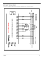
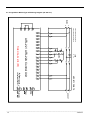
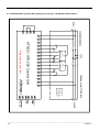
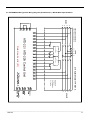
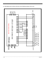
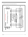
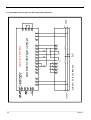
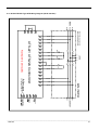
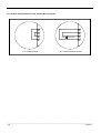
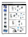
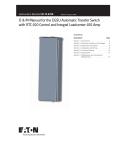
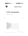
ATS-22A
Ver1.0
Automatic Transfer Switch Control Unit
Operation Manual
Headquarters : No.3, Lane 201, Chien Fu St., Chyan Jenn Dist., Kaohsiung, TAIWAN
Tel : + 886-7-8121771
Fax : + 886-7-8121775
URL : http://www.kutai.com.tw
TABLE OF CONTENTS
Section
Page
SECTOIN 1 : INTRODUCTION
1.1 Preliminary Comments And Safety Precautions ......................................................................................... 3
1.2 Overview ..................................................................................................................................................... 3
1.3 Product Overview........................................................................................................................................ 3
1.4 Functions / Features ................................................................................................................................... 3
SECTOIN 2 : OPERATOR PANEL
2.1 General ....................................................................................................................................................... 5
2.2 Display Window .......................................................................................................................................... 5
2.3 Function Buttons ......................................................................................................................................... 5
2.4 Panel LED Outputs ..................................................................................................................................... 5
SECTOIN 3 : OPERATION
3.1 General ....................................................................................................................................................... 6
3.2 AUTO Mode ................................................................................................................................................ 6
3.3 OFF Mode ................................................................................................................................................... 6
3.4 Manual Test Mode (TEST) ......................................................................................................................... 7
3.5 Programming Instruction ............................................................................................................................. 7
3.6 Remote Communication Instruction............................................................................................................ 7
3.7 KCU Remote Connection Passwords Recovery ........................................................................................ 8
3.8 Voltage Adjustment ..................................................................................................................................... 8
3.9 Line By Line Programming Table .............................................................................................................10
3.10 Specification Summary .............................................................................................................................11
SECTOIN 4 : INSTALLATION INSTRUCTIONS
4.1 General .....................................................................................................................................................12
4.2 Figure / Size / Installation Reference ........................................................................................................12
SECTOIN 5 : TYPICAL WIRING
APPENDIX : KCU MODULES CONNECTION ILLUSTRATION ........................................................................37
___________________________________________________________________________________________
2
ATS-22A
SECTION 1 : INTRODUCTION
1.1 Preliminary Comments and Safety Precautions
The manual covers installation, operation and
maintenance of the ATS-22A Automatic Transfer
Switch PLC Controller. This manual is for use by
authorized and qualified personnel only.
WARNING
High voltage will cause severe injury or death
1.2 Overview
Transfer switches protect critical electrical loads
against loss of power. A standby (emergency)
generator backs up the normal grid power. The transfer
switch connects Normal and Standby source supply to
the load. When power is lost from Normal source, the
transfer switch transfers the load to the standby source.
After power is restored, the ATS will transfer the load
back to Normal source.
1.3 Product Overview
The ATS-22A is a multifunction programmable logic
automatic transfer switch controller. Suitable for 1
phase and 3 phase system, including all necessary
monitoring and protections.
Controller’s features:
● Microprocessor based & Polycarbonate panel.
1
● Membrane switch button designed. *
● Compact size with user-friendly LED display.
● Programmable for cycle-mode or fix-mode displays for
3-phase and 1-phase voltages and frequencies.
● All programming and operations can be configured
on the front panel.
● Monitors Normal and Standby power for Over /
Under voltage anomalies.
● Monitors Normal and Standby power for Over /
Under frequency anomalies.
● Exercise with or without load.
● 1 week to 4 weeks automatic scheduled exercise /
testing.
● Transfer failure output signal.
● Pre-alert warning signal output for transferring
operation.
● Pre-alert warning signal output for scheduled
automatic Exercise / testing.
● Compatible with most ATS switches on the market.
● Communication Port for Remote Monitoring and
Control Options. (USB / RS485 / Ethernet / WI-FI
1
modules SIM Card). *
● Program on-site or from remote (mobile) device (PC,
2
Smartphone). *
● Auto-saved settings (memory preserved throughout
all power disconnects and resets).
● Front panel display provides source status and fail
alarm indications.
1.4 Functions / Features
The primary function of ATS-22A controller is to
monitor Normal / Standby power and to provide
seamless automatic transfer of load.
1.4.1 Operational Simplicity
From installation to programming and to usage, the
ATS-22A controller is designed with operational
simplicity in mind. The user-friendly front panel
interface simplifies routine operation, programming and
setting adjustments.
1.4.2 Standard Features
All logic settings for different ATS’s are
preprogrammed and stored in its non-volatile
random-access memory (NVRAM), this memory
retains its information when power is turned off. Some
features and set points are user adjustable.
1
Software version REV.3, REV.3.1 ,REV.4 are not
available for remote communication. System
voltage 180 Vac or above is required to use with
optional KCU-40 or KCU-50 communication
module.
2
KCU communication module option is required.
*
*
___________________________________________________________________________________________
ATS-22A
3
Feature 1 : Time Delay Emergency to Normal
(TDEN)
TDEN delays the transfer from the emergency source
to the normal Source to permit stabilization of the
normal source before retransfer is made. Timing
begins when the normal source becomes available.
(Refer to program table line 3)
Adjustable TDEN time range:0.0 − 999 sec.
Feature 2 : Time Delay Normal to Emergency
(TDNE)
U/V adjustment range:80 − 470 Vac
U/V reset value:+10 Vac (Not adjustable)
Feature 7 : Under / Over Frequency Sensing
The controller monitors Normal and Standby source
frequency. The client can set the over & under
frequency range. (Refer to program table line 11, 12,
13, 17, 18 & 19)
O/F adjustable range:51 − 75 Hz
O/F reset value:-1 Hz (Not adjustable)
U/F adjustable range:40 − 59 Hz
TDNE delays the transfer from normal to emergency to
permit stabilization of the generator before the
retransfer is made. Timing begins when the standby
source becomes available. (Refer to program table line
4)
Adjustable TDEN time range:0.0 − 250 sec.
Feature 3 : Time Delay Engine Start (TDES)
The TDES Time (Delays Engine Start) this timer
prevents nuisance start because of momentary
electrical glitches. If power normalizes before the
countdown ends, the controller skips the engine start
and resets the timer. (Refer to program table line 5)
Adjustable TDES time range:0 − 30 sec.
Feature 4 : Time Delay Engine Cool-down (TDEC)
TDEC permits the generator to run unloaded after the
ATS retransfer back the load to Normal source. Timing
begins when the ATS connects back to Normal source.
(Refer to program table line 6)
Adjustable TDEC range:0 − 250 sec.
Feature 5 : Time Delay Center OFF Position
This timer temporally stops the switch in the center
OFF position (completely cut off) before proceeding to
Normal source. (Refer to program table line 7)
U/F reset value:-1 Hz (Not adjustable)
Feature 8 : Programmable exerciser
It can be set to exercise one time per week to one time
every 4 weeks on any day and time, with or without
load. The length of the exercise is also set. (Refer to
program table line 23, 24, 25, 26 & 27)
Feature 9 : Failure Warning Output
The controller also has one dry contact that can be set
to react to one of four warning. (Refer to program table
line 30)
●
●
●
●
Transfer failure warning
Pre-transfer warning
Pre-test / exercise warning
When ATS is in emergency position warming
NOTICE
ATS-22A provides one auxiliary contact for
external output signal for Transfer Failure,
Pre-transfer or Pre-exerciser alarm output.
Feature 10 : Controller Panel Lighting Test
This checks the LED lights. Press the OFF button twice,
all panel LEDs must light up.
Adjustable time delay range:0 − 99 sec.
Feature 6 : Full Phase Over / Under Voltage and
Loss of Phase Sensing
The controller monitors full phase output voltage from
Normal and Standby source. The user can program
over & under voltage window. (Refer to program table
line 8, 9, 10, 14, 15 & 16)
O/V adjustment range:110 − 530 Vac
O/V reset value:-10 Vac (Not adjustable)
___________________________________________________________________________________________
4
ATS-22A
SECTION 2 : OPERATOR PANEL
2.3.3 AUTO Button
2.1 General
● Front Display Window
● Function Buttons
● Panel LEDs Display
When selecting the AUTO button, the ATS-22A runs in
automatic mode (AUTO) lighting the corresponding
LED to indicate the selection. The controller
automatically starts the generator, transfer and
retransfers from Normal to Standby source as
commanded by the features supplied and the
preprogrammed setting.
2.2 Display Window
2.3.4 TEST Button
The ATS-22A controller has a four-digit, seven-segment
displayer to monitor all parameters, setting and
messages.
Pressing the TEST button simulates a power failure In
TEST the generator starts and begins a
preprogrammed execution and testing sequence made
with or without loading the generator. (Refer to
program line 28)
Get acquainted with the ATS-22A:
The screen display’s:
● Full phase voltage / frequency display
● Current Time HH:MM (In OFF only)
2.3.5 OFF Button
● Time delay countdown display
● Program setting parameter display
Pressing the OFF again, turns the ATS-22A OFF
engaging a flashing red LED instantly disabling all
functions and the screen shows the current time.
2.3 Function Buttons
The front panel employs five membrane switch
buttons.
2.4 Panel LED Outputs
Eight individual red and blue LEDs light bars perform or
indicating each function.
2.3.1 Increase (▲) Button
Information concerning the LEDs output
In AUTO Mode, each press of the up (▲) button
changes the display to the next phase voltage reading.
However, when programming every press of the up (▲)
button increases the displayed parameter by a single
unit. If held, the up (▲) button continues to scroll.
Power available display Normal & Standby
2.3.2 Decrease (▼) Button
In AUTO Mode, each press of the down (▼) button
changes the display between voltage, duty time and
frequency.
However, when programming every press of the down
(▼) button decreases the displayed parameter by a
single unit. If held, the down (▼) button continues to
scroll.
Normal over voltage
___________________________________________________________________________________________
ATS-22A
5
Normal under voltage
Normal transfer failure
Normal over frequency
Standby transfer failure
SECTION 3 : OPERATION
3.1 General
The five functions of the ATS-22A:
Normal under frequency
Standby over voltage
●
●
●
●
●
AUTO Mode
OFF Mode
Manual Test Mode (TEST)
Programming Instruction
Remote Communication Instruction
The practical use of each operation under each
category will be explained in this section. It is assumed
that prior sections are understood, and the operator
has a basic understanding of the hardware.
3.2 AUTO Mode
The AUTO mode provides automatic engine start, stop,
and power transfer and retransfers from source to
source as dictated by the values previously
programmed.
Standby under voltage
The ATS-22A constantly monitors the condition of both
Normal and Standby source.
3.3 OFF Mode
Standby over frequency
Standby under frequency
In OFF mode, the ATS-22A disables all the transfers
and protection functions with all LED indicators off
leaving the display screen only showing the time. User
can test the LEDs by pressing the OFF button twice.
Check and reset the clock every year. The wrong time
can affect the schedule exerciser. Without power, the
controller can maintain the clock working for up to a
week.
However, when programming, the OFF button allows you
to move to the next program line and then change the
values for that line using down (▼) and up (▲) buttons.
___________________________________________________________________________________________
6
ATS-22A
3.4 Manual Test Mode (TEST)
3.6 Remote Communication Instruction
Pressing TEST simulate a loss of Normal power source.
Permitting the controller to start the engine and carry
out a power transfer. TEST can be with load or without
load.
You can monitor and control two gen-sets on a remote
PC/Smartphone using the remote communication
modules manufactured by Kutai Electronics.
To end, press the AUTO button. If Normal power is
available, the controller transfer back to Normal and
the engine follow the program shutdown procedure to
stop the generator. However, by pressing the OFF
button, the transfer switch remains in its current
position stopping the engine, and bypassing all time
delays.
3.5 Programming Instruction
Program the controller from the front faceplate.
To start, set the controller to OFF and press & hold the
OFF button for 4 seconds. The word “Vr1.0” appears
on the display for 2 seconds, showing the software
version.
You are now ready to start the line-by-line
programming sequence. Always press the OFF button
to move to the next line. To change the parameter, on
each line use the up (▲) and down (▼) arrows.
Repeatedly pressing the up (▲) or down (▼) button,
changes the displayed by one. To change faster, hold
the buttons down.
Remember to always press the “OFF” button to move
to the next line or until the “End” appears on the
screen.
Note:To end and exit at any time, hold the “OFF”
button down for 4 seconds.
If you make an error or need to return to factory
settings, stay or reenter programming and then hold
the AUTO button down for 4 seconds, until the word
“Au.Po” appears on the screen verifying that all
programming lines are factory reset back like in the
manual. (See line-by-line programming table for
ATS-22A factory settings).
MODEL
COMMUNICATION INTERFACE
KCU-01
USB
KCU-02
RS-485
KCU-30
Ethernet (Dynamic IP)
KCU-40
WI-FI
KCU-50
3G SIM Card
WARNING
A remote start signal can start an engine via
ATS-22A without warning. Place a "Danger" sign
next to the generator stating it can start anytime!
A warning buzzer / light installed is
recommended. Unexpected engine starts can
result in serious injury or death. When
performing service or maintenance, always
disconnect the remote start signal input.
When KCU-30, KCU-40, KCU-50 module is installed
on ATS-22A, it allows you to remote monitor or operate
ATS and generator via iphone or Android mobil phones.
Free App software currently available for Apple iOS5.1
system or above and android operating system.
Download “Remote Communication” free software by
searching “Kutai” in Apple Store or Google Play.
The corresponding program settings for ATS-22A
installed with KCU-XX module includes item (32), (33),
(34) Programming item (32) is a must. When Item (32)
is set to "00" Disable, then the remote monitoring
software is restricted to read information only whereas
remote command is strictly forbidden.
When KCU-02 – RS-485 communication module is
installed, additional program setting on lines (33) and
(34) are required.
Refer to KCU-XX hardware and software manual for
detail information
WARNING
ATS-22A with KCU-02 module constitutes a
closed LAN network. Each controller address can
be setup range from 1 to 99 and not to be
repeated. The transmission rate must be the
same!
___________________________________________________________________________________________
ATS-22A
7
The installation for the KCU-XX communication module
on the ATS-22A controller is fairly simple.
Step 1 : Remove the slot cover from the back of
controller.
NOTICE
Program Line 36 is only available when KCU
Module is installed on the ATS-22A controller.
3.8 Voltage Adjustment
The ATS-22A voltage readings are factory set and
calibrated. However, if you need to modify any voltage
reading, follow these steps.
Step 1:Ensure supply is connected to both the normal
and standby line sides before undertaking Voltage
calibration, and then manually start standby generator
to generate power.
Step 2:Enter Program mode and set the program item
(35) to (01). “VAdJ” will appear on the display window.
Step 2:Insert KCU-XX module into the slot and tighten
the screw.
Step 3:Select the phase you wish to re-calibrate by
pressing the OFF button.
EX. Normal Source Phase L12 Calibration
3.7 KCU Remote Connection Passwords Recovery
Step 1:Make sure the KCU module is installed on the
controller before carrying out remote connection
passwords recovery.
EX. Emergency Source Phase L23 Calibration
Step 4:Use a good quality voltmeter as a reference to
calibrate the ATS-22A voltage reading to the desired
phase.
Step 2:Enter Program mode and set the program item
(36) to (01) and press OFF button. 4-digit numbers
“0000” and “9999” will appear on the display window
about two seconds. Then “End” appears which means
passwords have been restored successfully.
___________________________________________________________________________________________
8
ATS-22A
Step 5:With the up (▲) and down (▼) buttons reset
the voltage reading on the ATS-22A.
Step 6:Press the “OFF” button to move to the next
phase or until the word “End” appears on the screen.
To exit hold the “OFF” button at any time for 4 sec.
End Programming Display
Step 7:If you get “FAIL”, the calibration is null. Press
the OFF button to reset and repeat Step 1.
Calibration Failure
SECURITY NOTICE AND LIABILITY DISCLAIMER
You are responsible for keeping your KCU
Remote
Connection
Passwords
(Administrator/Viewer) safe and confidential
because they are the key to access your
equipments.
There will be potentially serious security issues if
your passwords are compromised. Some of the
risks of compromised security include the
equipment being remotely controlled by third
parties, who may have criminal intent and
malicious damage to your equipments.
We are entitled to rely on any use of our
connection services using that password as being
use by you and authorized by you. If you know or
believe that there is any unauthorized, fraudulent
or unlawful use of your password, you must reset
it in the controller. (Refer to controllers user
manual for connection password reset)
___________________________________________________________________________________________
ATS-22A
9
3.9 Line By Line Programming Table
VALUE
FACTORY
SETTING
01
LINE
DESCRIPTION
1
Is this ATS operating in 1 Phase or 3 Phase?
00
2
Select Switch ATS type
See drawing on the back of this manual for
guide on different ATS types
00) MCCB BTS type ATS (Single motor)
01) Mot type (MCCB with separate motor)
02) Air circuit breaker type (ACB)
03) Double throw type (Without OFF position)
04) Double throw type (With OFF position)
05) Kutai TS-XXX type ATS
06) Magnetic contactor type ATS (MC)
3
TDEN Time Delay Emergency to Normal
00 − 999 sec.
10 sec.
4
TDNE Time Delay Normal to Emergency
00 − 250 sec.
10 sec.
5
TDES Time Delay Engine Start
00 − 30 sec.
5 sec.
6
TDEC Time Delay Engine Cool-down
00 − 250 sec.
30 sec.
7
Time Delay in the OFF Position
00 − 99 sec.
5 sec.
8
Normal over voltage protection setting
11 − 53 ( 110 − 530V )
25 (250V)
9
Normal under voltage protection setting
08 − 47 ( 80 − 470V )
18 (180V)
10
Time delay if there is a problem with the
Normal voltage
00 − 99 sec.
( 0 = Disable voltage monitoring )
11
Normal over frequency protection setting
51 − 75 Hz
65 Hz
12
Normal under frequency protection setting
40 − 59 Hz
55 Hz
13
Time delay if there is a problem with the
Normal frequency
00 − 99 sec.
( 0 = Disabled Hz monitoring )
14
Generator over voltage protection setting
11 − 53 ( 110 − 530V )
25 (250V)
15
Generator under voltage protection setting
8 − 47 ( 80 − 470V )
18 (180V)
16
Time delay if there is a problem with
emergency voltage output
00 − 99 sec.
(0 = Function disabled)
17
Generator over frequency setting
51 − 75 Hz
65 Hz
18
Generator under frequency setting
40 − 59 Hz
55 Hz
19
Time delay if there is a problem with the
Generator frequency
00 − 99 sec.
(0 = Function disabled)
10 sec.
20
Set today’s day of the week– Day
1 − 7 ( Monday to Sunday )
current
21
Set today’s hour – hour
00 − 23
Current
22
Set today’s minutes
00 − 59
current
23
Set day of week to do the engine exercise
1 − 7 ( Monday to Sunday )
6
24
Set the time to start the exercise
00 − 23 ( 24 Hr Mode )
12
25
Set generator automatic exercise cycle
01) 1 week
02) 2 weeks
26
Exercising duration
00 − 99 minutes ( 0 = Do not exercise )
00
27
Exercise with load or without load
00) Without load
01) With load
00
28
Test with load or without load
00) Without load
01) With load
01
29
Display setting
00) Cyclic Mode
01) Fix Mode
00
1 Phase
01
3 Phase
00
10 sec.
10 sec.
10 sec.
03) 3 weeks
04) 4 weeks
01
___________________________________________________________________________________________
10
ATS-22A
LINE
DESCRIPTION
FACTORY
SETTING
VALUE
30
Program the auxiliary contact output
00) Transfer failure
01) Pre-transfer
02) Pre-exerciser
03) When the ATS is in emergency position
31
Pre-transfer / Pre-exercising time delay
before transfer load from one source to
another source
00 − 99 sec.
32
Remote control by KCU-XX module
00
33
KCU-02 module address
00
KCU-02 module restricted
01 − 99
34
KCU-02 module transmission rate
01
02
03
115200
57600
38400
35
Enter AC voltage correction
00
No
01
Yes
00
36
Restore KCU Remote Connection Passwords
to original factory default settings.
(Administrator : 0000, Viewer : 9999)
00
No
01
Yes
00
Disable
01
04
05
06
19200
14400
9600
01
10
00
Enable
00
07
08
09
4800
2400
1200
03
3.10 Specification Summary
DESCRIPTION
SPECIFICATION
AC Voltage Measurement Range
50 − 550 Vac
Frequency Measurement Range
40 − 75 Hz
Remote Start Contact
7A @ 250 Vac Max
Normal ON Contact
7A @ 250 Vac Max
50/60 Hz
Emergency ON Contact
7A @ 250 VaC Max
Auxiliary Contact Output
7A @ 250 Vac Max
Operating Temperature
-20 − +70 °C
Storage Temperature
-30 − +80 °C
Relative Humidity
Max. 90%
Panel Cut-Out
113.0 (L) x 168.0 (W) +/- 0.5 mm
Dimensions
125.0 (L) x 180.0 (W) x 42.0 (H) mm
Weight
495 g +/- 2%
___________________________________________________________________________________________
ATS-22A
11
SECTION 4: INSTALLATION INSTRUCTIONS
4.1 General
The ATS-22A is made for front panel mounting.
4.2 Figure / Size / Installation Reference ( All Dimensions in mm. )
___________________________________________________________________________________________
12
ATS-22A
SECTION 5 : TYPICAL WIRING
5.1 Single motor MCCB Type ATS Wiring Diagram (3P/4P 220 Vac) - Called BTS Switch
MAINS
L1
L2
L3
N
#ELS>>Genset Auxiliary Switch
#NLS>>Normal Auxiliary Switch
L1
ATS-22 / ATS-22A Control Unit
L3
LOAD
L2
N
Note:Line-2 set to (00)
MCCB TYPE BTS
L1
L2
L3
N
GENSET
___________________________________________________________________________________________
ATS-22A
13
5.2 Single Motor MCCB Type ATS Wiring Diagram (2P 220 Vac)
MAINS
L1
L2
#NLS>>Normal Auxiliary Switch
L1
LOAD
L2
#ELS>>Genset Auxiliary Switch
ATS-22 / ATS-22A Control Unit
Note:Line-2 set to (00)
MCCB TYPE BTS
L1
L2
GENSET
___________________________________________________________________________________________
14
ATS-22A
5.3 TERASAKI MOT Type ATS Wiring Diagram (3P/4P 220 Vac) - MCCB With Separate Motor
MAINS
L1
L2
L3
N
#ELS>>Genset Auxiliary Switch
#NLS>>Normal Auxiliary Switch
L1
L2
A(On)
L3
LOAD
D(P2)
B(Off)
N-MOTOR UNIT
C(P1)
N
D(P2)
B(Off)
C(P1)
E-MOTOR UNIT
A(On)
TERASAKI MOT TYPE BTS
B(Off): Trip Coil
A(On): Close Coil
D(P2): Common
C(P1): Charge Motor
L1
L2
L3
N
GENSET
15
ATS-22A
ATS-22 / ATS-22A Control Unit
Note:Line-2 set to (01)
___________________________________________________________________________________________
5.4 TERASAKI MOT Type ATS Wiring Diagram (2P 220 Vac) - MCCB With Separate Motor
MAINS
L1
L2
L1
LOAD
A(On)
L2
#ELS>>Genset Auxiliary Switch
#NLS>>Normal Auxiliary Switch
D(P2)
B(Off)
N-MOTOR UNIT
C(P1)
D(P2)
B(Off)
C(P1)
E-MOTOR UNIT
A(On)
TERASAKI MOT TYPE BTS
B(Off): Trip Coil
A(On): Close Coil
D(P2): Common
C(P1): Charge Motor
L1
L2
GENSET
ATS-22A
16
ATS-22 / ATS-22A Control Unit
Note:Line-2 set to (01)
___________________________________________________________________________________________
5.5 MITSUBISHI MD Type ATS Wiring Diagram (3P/4P 220 Vac) - MCCB With Separate Motor
MAINS
L1
L2
L3
N
#EAU>>Genset Auxiliary Switch
#NAU>>Normal Auxiliary Switch
L1
L2
B
L3
LOAD
A1
C
N-MOTOR UNIT
A2
N
B
A1
A2
E-MOTOR UNIT
C
MITSUBISHI MD TYPE BTS
B: Close Coil
A2: Charge Motor
C: Trip Coil
A1: Common
L1
L2
L3
N
GENSET
17
ATS-22A
ATS-22 / ATS-22A Control Unit
Note:Line-2 set to (01)
___________________________________________________________________________________________
5.6 MITSUBISHI MD Type ATS Wiring Diagram (2P 220 Vac) - MCCB With Separate Motor
MAINS
L1
L2
L1
LOAD
B
L2
#EAU>>Genset Auxiliary Switch
#NAU>>Normal Auxiliary Switch
A1
C
N-MOTOR UNIT
A2
B
A1
A2
E-MOTOR UNIT
C
MITSUBISHI MD TYPE BTS
B: Close Coil
A2: Charge Motor
C: Trip Coil
A1: Common
L1
L2
GENSET
ATS-22A
18
ATS-22 / ATS-22A Control Unit
Note:Line-2 set to (01)
___________________________________________________________________________________________
5.7 Air Circuit Breaker Type ATS Wiring Diagram (3P/4P 220 Vac)
Merlin Gerin MCB Type ATS Wiring Diagram (3P/4P 220 Vac)
MAINS
L1
L2
L3
N
#2-OF>>Genset Auxiliary Switch
#1-OF>>Normal Auxiliary Switch
L1
L2
L3
LOAD
N
ACB TYPE BTS
MG MCB TYPE BTS
XF: Close Coil
MX1: Trip Coil
MCH: Charge Motor
L1
L2
L3
N
GENSET
19
ATS-22A
ATS-22 / ATS-22A Control Unit
Note:Line-2 set to (02)
___________________________________________________________________________________________
5.8 Air Circuit Breaker Type ATS Wiring Diagram (2P 220 Vac)
Merlin Gerin MCB Type ATS Wiring Diagram (2P 220 Vac)
MAINS
L1
L2
L1
LOAD
L2
#2-OF>>Genset Auxiliary Switch
#1-OF>>Normal Auxiliary Switch
ATS-22 / ATS-22A Control Unit
Note:Line-2 set to (02)
ACB TYPE BTS
MG MCB TYPE BTS
XF: Close Coil
MX1: Trip Coil
MCH: Charge Motor
L1
L2
GENSET
___________________________________________________________________________________________
20
ATS-22A
5.9 Double Throw Type ATS Without OFF Position Wiring Diagram (3P/4P 220 Vac) – With A1, A2 & B1, B2
MAINS
L1
L2
L3
N
#ELS>>Genset Auxiliary Switch
#NLS>>Normal Auxiliary Switch
L1
DOUBLE THROW TYPE
WITHOUT OFF POSITION
CS2
L2
N
CS1
CS2
L3
L3
LOAD
CS1
CS2
N
L2
CS1
CS2
L1
CS1
( B1,B2 ): Genset ON
( A1,A2 ): Mains ON
GENSET
21
ATS-22A
ATS-22 / ATS-22A Control Unit
Note:Line-2 set to (03)
___________________________________________________________________________________________
5.10 Double Throw Type ATS Without OFF Position Wiring Diagram (2P 220 Vac) – With A1, A2 & B1, B2
MAINS
L1
L2
L1
LOAD
CS1
CS2
CS2
L2
#ELS>>Genset Auxiliary Switch
#NLS>>Normal Auxiliary Switch
CS1
DOUBLE THROW TYPE
WITHOUT OFF POSITION
( B1,B2 ): Genset ON
( A1,A2 ): Mains ON
L1
L2
GENSET
ATS-22A
22
ATS-22 / ATS-22A Control Unit
Note:Line-2 set to (03)
___________________________________________________________________________________________
5.11 Double Throw Type ATS Without OFF Position Wiring Diagram (3P/4P 220 Vac) – With S1 & S2 Coils
MAINS
L1
L2
L3
N
#ELS>>Genset Auxiliary Switch
#NLS>>Normal Auxiliary Switch
L1
DOUBLE THROW TYPE
WITHOUT OFF POSITION
CS2
L2
N
CS1
CS2
L3
L3
CS1
CS2
N
L2
LOAD
CS1
CS2
L1
CS1
S1: Mains Close Coil
S2: Genset Close Coil
GENSET
23
ATS-22A
ATS-22 / ATS-22A Control Unit
Note:Line-2 set to (03)
___________________________________________________________________________________________
5.12 Double Throw Type ATS Without OFF Position Wiring Diagram (2P 220 Vac) – With S1 & S2 Coils
MAINS
L1
L2
L1
LOAD
CS2
L2
L1
DOUBLE THROW TYPE
WITHOUT OFF POSITION
CS1
CS2
L2
#ELS>>Genset Auxiliary Switch
#NLS>>Normal Auxiliary Switch
CS1
S1: Mains Close Coil
S2: Genset Close Coil
GENSET
ATS-22A
24
ATS-22 / ATS-22A Control Unit
Note:Line-2 set to (03)
___________________________________________________________________________________________
5.13 Double Throw Type ATS With OFF Position Wiring Diagram (3P/4P 220 Vac)
With A1,A2 & AT1,AT2 & B1,B2 & BT1,BT2 Terminals
MAINS
L1
L2
L3
N
#ELS>>Genset Auxiliary Switch
#NLS>>Normal Auxiliary Switch
L1
DOUBLE THROW TYPE
WITH OFF POSITION
CS2
L2
N
CS1
CS2
L3
L3
CS1
CS2
N
L2
LOAD
CS1
CS2
L1
CS1
( A1, A2 ): Mains ON
( AT1,AT2 ): Mains Trip
( B1, B2 ): Genset ON
( BT1,BT2 ): Genset Trip
GENSET
25
ATS-22A
ATS-22 / ATS-22A Control Unit
Note:Line-2 set to (04)
___________________________________________________________________________________________
5.14 Double Throw Type ATS With OFF Position Wiring Diagram (2P 220 Vac)
With A1,A2 & AT1,AT2 & B1,B2 & BT1,BT2 Terminals
MAINS
L1
L2
L1
LOAD
CS2
L2
L1
DOUBLE THROW TYPE
WITH OFF POSITION
CS1
CS2
L2
#ELS>>Genset Auxiliary Switch
#NLS>>Normal Auxiliary Switch
CS1
( A1, A2 ): Mains ON
( AT1,AT2 ): Mains Trip
( B1, B2 ): Genset ON
( BT1,BT2 ): Genset Trip
GENSET
ATS-22A
26
ATS-22 / ATS-22A Control Unit
Note:Line-2 set to (04)
___________________________________________________________________________________________
5.15 SOCOMEC ATyS-3e & ATyS-6 & ATyS-6e Type ATS Wiring Diagram (3P/4P 220 Vac)
MAINS
L1
L2
L3
N
L1
SOCOMEC ATyS-3e TYPE BTS
SOCOMEC ATyS-6 TYPE BTS
SOCOMEC ATyS-6e TYPE BTS
CS2
L2
N
CS1
CS2
L3
L3
CS1
CS2
N
L2
LOAD
CS1
CS2
L1
CS1
GENSET
27
ATS-22A
ATS-22 / ATS-22A Control Unit
Note:Line-2 set to (04)
___________________________________________________________________________________________
5.16 SOCOMEC ATyS-3e & ATyS-6 & ATyS-6e Type ATS Wiring Diagram (2P 220 Vac)
MAINS
L1
L2
CS2
L2
L1
L1
CS1
CS2
L2
LOAD
CS1
SOCOMEC ATyS-3e TYPE BTS
SOCOMEC ATyS-6 TYPE BTS
SOCOMEC ATyS-6e TYPE BTS
ATS-22 / ATS-22A Control Unit
Note:Line-2 set to (04)
GENSET
___________________________________________________________________________________________
28
ATS-22A
5.17 SOCOMEC ATyS-3S type ATS Wiring Diagram (3P/4P 220 Vac)
MAINS
L1
L2
L3
N
CS1
CS1
CS1
CS2
CS2
CS2
CS2
N
L3
L2
L1
L1
CS1
L2
L3
LOAD
N
SOCOMEC ATyS-3S TYPE BTS
ATS-22 / ATS-22A Control Unit
Note:Line-2 set to (04)
GENSET
___________________________________________________________________________________________
ATS-22A
29
5.18 SOCOMEC ATyS-3S type ATS Wiring Diagram (2P 220 Vac)
MAINS
L1
L2
CS2
L2
L1
L1
CS1
CS2
L2
LOAD
CS1
SOCOMEC ATyS-3S TYPE BTS
ATS-22 / ATS-22A Control Unit
Note:Line-2 set to (04)
GENSET
___________________________________________________________________________________________
30
ATS-22A
5.19 KUTAI TS-XXX Type ATS Wiring Diagram (3P/4P 220 Vac)
MAINS
N1
N2
N3
#NLS>>Normal Auxiliary Switch
#ELS>>Genset Auxiliary Switch
NLS
LOAD
L3
CN1-11
CS2
L2
CS1
CS2
L1
CS1
CS2
220V
CS1
ELS
COIL
KUTAI TS3P125
E1
E2 GENSET
E3
31
BROWN
CN1-1
GREEN
CN1-5
WHITE
CN1-9
BLACK
CN1-10
BLUE
CN1-6
CN1-2
PINK
RED
ORANGE
CN1-3
RED/WHITE
CN1-12
GRAY
CN1-8
YELLOW
CN1-4
ATS-22A
ATS-22 / ATS-22A Control Unit
Note:Line-2 set to (05)
___________________________________________________________________________________________
5.20 KUTAI TS-XXX Type ATS Wiring Diagram (2P 220 Vac)
MAINS
N1
N2
#NLS>>Normal Auxiliary Switch
#ELS>>Genset Auxiliary Switch
NLS
LOAD
L2
CS2
L1
CS1
CS2
220V
CS1
ELS
COIL
KUTAI TS2P125
E1 GENSET
E2
ATS-22A
BROWN
CN1-1
WHITE
CN1-9
BLACK
CN1-10
BLUE
CN1-6
CN1-11
CN1-2
PINK
RED
ORANGE
CN1-3
RED/WHITE
CN1-12
YELLOW
CN1-4
32
ATS-22 / ATS-22A Control Unit
Note:Line-2 set to (05)
___________________________________________________________________________________________
5.21 Magnetic Contactor Type ATS Wiring Diagram (3P/4P 220 Vac)
MAINS
L1
L2
L3
N
#ELS>>Genset Auxiliary Switch
#NLS>>Normal Auxiliary Switch
L1
MAGNETIC CONTACTOR TYPE
MC2
L2
N
MC1
MC2
L3
L3
MC1
MC2
N
L2
LOAD
MC1
MC2
L1
MC1
MC1: Mains Close Coil
MC2: Genset Close Coil
GENSET
33
ATS-22A
ATS-22 / ATS-22A Control Unit
Note:Line-2 set to (06)
___________________________________________________________________________________________
5.22 Magnetic Contactor Type ATS Wiring Diagram (2P 220 Vac)
MAINS
L1
L2
L1
LOAD
MC2
L2
L1
MAGNETIC CONTACTOR TYPE
MC1
MC2
L2
#ELS>>Genset Auxiliary Switch
#NLS>>Normal Auxiliary Switch
MC1
MC1: Mains Close Coil
MC2: Genset Close Coil
GENSET
ATS-22A
34
ATS-22 / ATS-22A Control Unit
Note:Line-2 set to (06)
___________________________________________________________________________________________
5.23 3 Phase 4 Wire 380V Without PT (Transformer) Wiring Diagram
MAINS
AC380V
L1
L2
L3
N
#ELS>>Genset Auxiliary Switch
#NLS>>Normal Auxiliary Switch
L1
L3
LOAD
L2
N
MCCB TYPE BTS
L1
L2
L3
N
AC380V
GENSET
35
ATS-22A
ATS-22 / ATS-22A Control Unit
Note:Line-2 set to (00)
___________________________________________________________________________________________
5.24 System Voltage Different From AC220V Wiring Diagram
220V
For AC220V System
380/440/480V
For AC380/440/480V System
___________________________________________________________________________________________
36
ATS-22A
APPENDIX : KCU Modules Connection Illustration
Remote Communication
Function Supported Models
KUTAI Remote Communication Modules
AMF-10
GCU-100
ATS-22
ATS-33
ATS-34
ATS-PLC
GCU-3000
___________________________________________________________________________________________
ATS-22A
37