1
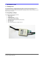
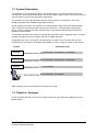
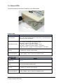
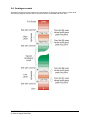
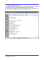
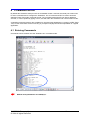
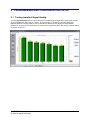
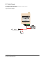
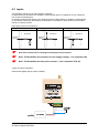
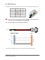
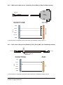
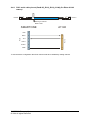
Product Documentation User Manual SMARTONE System Telecommunications Products SMARTOO Telemetry System © 2014 All rights Reserved 1 TABLE OF CONTENTS TABLE OF CONTENTS ........................................................................................................ 2 1 INTRODUCTION ............................................................................................................ 3 1.1 Background .................................................................................................... 3 1.2 SmartOne in Short.......................................................................................... 3 1.3 System Description ........................................................................................ 4 1.4 Digital vs. Analogue........................................................................................ 4 1.5 Status LEDs ................................................................................................... 5 1.6 The Ultimate in Stability – Comm Alive! ............................................................... 6 1.7 GPRS Manager .............................................................................................. 6 1.8 SmartOne Labels ........................................................................................... 7 2 EVENTS ......................................................................................................................... 7 2.1 Digital Input events ......................................................................................... 7 2.2 Timer events................................................................................................... 7 2.3 User Variable events ...................................................................................... 7 2.4 Analogue events............................................................................................. 8 3 SMARTONE START-UP ................................................................................................ 9 4 COMMAND MODE ....................................................................................................... 10 4.1 Entering Commands..................................................................................... 10 5 PROGRAMMING AND CONFIGURATION VIA YAT .................................................... 11 5.1 Testing Installed Signal Quality .................................................................... 11 6 SMARTONE ELECTRICAL INTERFACES ................................................................... 12 6.1 DC Power Supply ......................................................................................... 12 6.2 Digital Outputs .............................................................................................. 13 6.3 Inputs ........................................................................................................... 14 6.4 RS232 Data port........................................................................................... 16 6.4.1 PC serial cable pin-out (Part# SO_RJ12_DB9_PC) ......................................... 16 6.4.2 DB25 serial cable pin-out (Part# SO_RJ12_DB25_A1700) (for Elster meters) 17 6.4.3 RJ12 serial cable pin-out (Part# SO_RJ12_RJ12_ZMD ) (for Landis&Gyr meters) 17 6.4.4 RJ12 serial cable pin-out (Part# SO_RJ12_RJ12_A1140) (for Elster A1140 meters) 18 7 ELECTRICAL SPECIFICATIONS ................................................................................. 19 8 OTHER SPECIFICATIONS .......................................................................................... 19 8.1 Physical ........................................................................................................ 19 8.2 Manufacturer’s Type Number ....................................................................... 19 9 DISCLAIMER ............................................................................................................... 20 10 GLOSSARY .............................................................................................................. 20 11 REVISION INFORMATION ....................................................................................... 20 12 CONTACTING TRUTEQ WIRELESS ........................................................................ 21 13 NOTICES & TRADEMARKS ..................................................................................... 21 SMARTOO Telemetry System © 2014 All rights Reserved 2 1 INTRODUCTION 1.1 Background The Truteq SmartOne is a versatile industrial RTU (Remote Terminal Unit) with integral modem for communications to IEDs (Intelligent Electronic Devices). It can be used in a whole range of applications in the telemetry, AMR (Automated Meter Reading), SCADA, security, farming, home and office automation industries. 1.2 SmartOne in Short The SmartOne has the following features: RS232 modem port Activity LEDs External DC input 2 Digital Open collector outputs 2 Inputs (either Analog or Digital) Dual SIM card feature (internal Chip SIM optional) Data logging card Real Time Clock Easy scripting language to configure the unit SMARTOO Telemetry System © 2014 All rights Reserved 3 1.3 System Description The SmartOne is a smart telemetry device, but still supports AT commands, including the Hayes command set. Even though the SmartOne can act like a GSM modem, it offers much more in terms of communications, inputs, and event-based programming. The SmartOne is a type class B GPRS multi-slot class 10 device. It is intended for use on the 900MHz (extended) and 1800MHz GSM frequency bands. By using simple commands, the SmartOne can switch between using CSD (circuit switched data) calls, or GPRS to communicate with a device on the serial port. Two fully programmable inputs, timers, counters, variables and other events provide a very powerful and future-proof solution for industrial communications. The SmartOne executes the scripted Commands that are linked to all the triggered events, as well as scripted Commands received via SMS / CSD call or GPRS connection. A triggered event can be, for instance, an input going from high to low or the timer that runs out. Commands can, for instance, send SMS, report status to a server, toggle an output or clear a timer. Events Command Lists Event A Script linked to event A <Command> <Command> <Command> <Command>; Script linked to event B <Command> <Command> <Command> <Command> <Command>; Event B Event C Script linked to event C Script contained in SMS <Command> <Command> <Command> SMS messages sent to the SmartOne are executed as a script. 1.4 Digital vs. Analogue Unless specified otherwise, all inputs and outputs referred to in this manual are Digital inputs and Digital Outputs SMARTOO Telemetry System © 2014 All rights Reserved 4 1.5 Status LEDs Two LEDs indicate a whole list of statuses to the field installer. Information LED Heartbeat LED Heartbeat LED: Meaning States Power present Flash. This LED will always flash in some state – also indicating the unit being on and operational GSM Network state 50% on 50% off slow flash: No Network found Short Blip : Logged on to GSM network Double Short Blip : Logged on to GPRS network Short flash : Logged on to GSM network – low signal Double Short flash : Logged on to GPRS network – low signal Receive On flashing off : Modem receives data Data Carrier Detect On with off Blips : Busy in data call or GPRS session Information LED: Meaning States Modem Idle LED off SMS 50% on 50% off flash: SMS activity Transmit On flashing off : Modem transmits data Data Carrier Detect On with off Blips : Busy in data call or GPRS session SMARTOO Telemetry System © 2014 All rights Reserved 5 1.6 The Ultimate in Stability – Comm Alive! Telemetry users know that their devices are often in remote or inaccessible areas. The last thing they can afford is to have to continuously visit a number of sites to reset these devices. There are four major causes of failures in GSM-based telemetry: 1. Lock-ups between modem and GSM network. 2. Not terminated data calls. 3. Loss of network authentication. 4. Unknown network or modem status. By using proven and patented technology, the SmartOne is kept as stable as possible. Depending on the customer’s preferences on order, the modem will reset under any of the following conditions: 1. Every 24 hours (only if not in data call). 2. If a data call is not terminated for longer than 45 minutes. 3. If the modem loses GSM network authentication for longer than 10 minutes. If the modem is in a data call when the 24hr reset cycle starts, the modem will wait for 10 minutes before resetting. The default reset options are : 1. Every 24 hours (only if not in data call). 2. If the modem loses GSM network registration for longer than 10 minutes. 1.7 GPRS Manager The SmartOne uses the GPRS bearer to establish a transparent serial link between the IED and the user application. GPRS networks have been designed for hand-held units to browse the internet with. Because of this the network will assume disconnects and re-connects from users via their hand-held units. Installing a modem in a remote and fixed location with no user intervention will require some sort of management of the GPRS link. The SmartOne is fitted standard with a GPRS manager. This manager ensures that the modem stays ready and connected on the GPRS network. Various parameters can be set to ensure connectivity to the meter at any given time. The manager includes a periodic ping to a specified server in order to keep the GPRS availability up. Command 161 specifies the manager time-outs. Parameter 1: GPRS re-attach interval. This parameter specifies the number of minutes to wait before re-attaching to the GPRS network. Parameter 2: GPRS error re-try interval. This parameter specifies the number of minutes to wait before re-attempting to attach to the GPRS network. Parameter 3: Connection no data flow time-out. This parameter specifies the number of minutes to allow no data to flow through an open TCP connection before assuming a 'ghost' connection. Refer to TruTalk commands 150 to 161 for all the various options. Combining CSD and GPRS: The GPRS manager automatically detach from GPRS network when a CSD call comes in. The call is then answered. When the CSD session is over then the modem will re-attach to the GPRS network. SMARTOO Telemetry System © 2014 All rights Reserved 6 BOTTOM: 1.8 SmartOne Labels The SmartOne is identified by the top and bottom labels. The Top label indicates the LEDs and IO connections and also the serial number. The serial number is visible from the top and includes the year of manufacture. The bottom label on the SmartOne indicates the Input power specification as well as the IMEI. i Input : 6 ~ 15Vdc 1.3A TA-2013/xxxx APPROVED 2 EVENTS An event is a change in condition and where certain commands then need to be executed. 2.1 Digital Input events Separate Command Lists are linked to the events where an input goes high (on/open) or low (off/closed). The delay times (also known as the “debounce” times) before the unit registers a change in input state can be configured. 2.2 Timer events Separate Command Lists are linked to the events where a timer runs out. There are 5 separate timers. 2.3 User Variable events Separate Command Lists are linked to the events where a user variable reaches one of its low or high levels. There are 5 different user variables, each with its own high and low levels. SMARTOO Telemetry System © 2014 All rights Reserved 7 2.4 Analogue events Separate Command Lists are linked to the events where an analogue value passes a certain level. The following diagram explains which command lists are associated with which level. SMARTOO Telemetry System © 2014 All rights Reserved 8 3 SMARTONE START-UP The SmartOne will print ‘BOOT’ information on start-up. This information is printed on the serial port at the last baud rate and framing that the SmartOne was set to with command 257. The SmartOne is ready for operation once the “Start-up complete!!” sentence is printed. One can now enter commands via command mode (AT$TT) or use it as a standard modem. SMARTOO Telemetry System © 2014 All rights Reserved 9 4 COMMAND MODE By default the SmartOne serial port acts as a standard modem. However this serial port is also used to enter commands and to configure the SmartOne. The AT command AT$TT is used to enter the standard Truteq Text mode command prompt. The command mode will time-out after a default 30 seconds, or can be quitted by typing <ctrl-z>, this will return the SmartOne into normal modem mode. A simplified command mode is also available for use with serial applications by entering AT$RT (Raw Text). In this mode there will be no echoing or prompts to simplify the serial encapsulation in a typical application. 4.1 Entering Commands Commands can be entered once the SmartOne is in command mode. Default serial parameters are: 9600,8,N,1. SMARTOO Telemetry System © 2014 All rights Reserved 10 5 PROGRAMMING AND CONFIGURATION VIA YAT 5.1 Testing Installed Signal Quality Use the Signal Strength tool in YAT to check the received signal strength of the serving cell as well as the neighbouring cells. Click on <Once> for a quick test, or <Repeat> to test the antenna at different positions. Timing Advance can be selected to determine and display the approximate distance to the serving cell. The first bar on the left is the signal strength to the serving cell and should be above 10 (green) SMARTOO Telemetry System © 2014 All rights Reserved 11 6 SMARTONE ELECTRICAL INTERFACES Inputs Serial Port Outputs SIM card DC power input 6.1 DC Power Supply The TruCom SmartOne DC input is protected against reverse polarity and over voltage. Input DC Min 6VDC Max 15VDC Max Power 10W Input Protection Tranzorb + Poly switch Typical connection diagram: SMARTOO Telemetry System © 2014 All rights Reserved 12 6.2 Digital Outputs The SmartOne digital outputs are protected open collector format. The output can sink 15Vdc 200mA Typical connection diagram: SMARTOO Telemetry System © 2014 All rights Reserved 13 6.3 Inputs The SmartOne inputs can be either Digital or Analogue. In Digital mode the SmartOne can activate an internal weak pull-up to enable the use of a potential free contact as a digital input. In Analogue mode that SmartOne can activate an internal voltage divider to enable the measurement of up to 22Vdc monitoring. Alternatively the SmartOne can activate an internal shunt load to enable the use of 4-20mA sensors. Input options (set via command 31) Voltage Divider (option 0) Pull-Up (option 1) SmartOne External Input Shunt (option 2) SmartOne External Input SmartOne External Input Note: The SmartOne also monitors its own supply voltage – see command 180 Note: The SmartOne also has pulse counters – see commands 87 & 88 Note: See command !33 for Analogue and Digital selection options Typical connection diagrams: Potential free digital (Pull-up option enabled): SMARTOO Telemetry System © 2014 All rights Reserved 14 Analogue Voltage (Voltage Divider option enabled): Analogue Current (Shunt option enabled): SMARTOO Telemetry System © 2014 All rights Reserved 15 6.4 RS232 Data port The RS232 port is the SmartOne primary data port. It is an RJ12.6 socket with the following pin-out: Pin number Description Direction 1 +4V Out 2 RX data Out 3 TX data In 4 Flow control In 5 Flow control Out 6 GND -- The flow in and out functions can be defined as: RTS, CTS, DCD, DTR, Note: RI or none – for more information see command 259 6.4.1 PC serial cable pin-out (Part# SO_RJ12_DB9_PC) DB9 Female RJ12.6 PC +4V0 1 RX-O 2 2 TX-I 3 3 RTS-I 4 7 CTS-O 5 8 GND 6 5 DB9-Female RJ12 SMARTONE To use the above configuration then RTS and CTS needs to be enabled by setting !259 1 1 SMARTOO Telemetry System © 2014 All rights Reserved 16 6.4.2 DB25 serial cable pin-out (Part# SO_RJ12_DB25_A1700) (for Elster meters) RJ12.6 DB25 Female A1700 1 8 RX-O 2 3 TX-I 3 2 RTS-I 4 CTS-O 5 5 GND 6 7 RJ12 +4V0 DB25-Female SMARTONE To use the above configuration then CTS needs to be enabled by setting !259 1 0 RJ12 serial cable pin-out (Part# SO_RJ12_RJ12_ZMD ) (for Landis&Gyr meters) MODEM 6.4.3 RJ12.6 RJ12.6 Add tag to indicate Modem side ZMD +4V0 1 RX-O 2 5 TX-I 3 2 RTS-I 4 CTS-O 5 GND 6 RJ12 RJ12 SMARTONE 3 To use the above configuration then flow control needs to be disabled by setting !259 0 0 SMARTOO Telemetry System © 2014 All rights Reserved 17 RJ12 serial cable pin-out (Part# SO_RJ12_RJ12_A1140) (for Elster A1140 meters) MODEM 6.4.4 RJ12.6 RJ12.6 Add tag to indicate Modem side A1140 +4V0 1 RX-O 2 3 TX-I 3 2 RTS-I 4 CTS-O 5 GND 6 RJ12 RJ12 SMARTONE 5 To use the above configuration then flow control needs to be disabled by setting !259 0 0 SMARTOO Telemetry System © 2014 All rights Reserved 18 7 ELECTRICAL SPECIFICATIONS Power supply: Input Low voltage DC Min 6VDC Antenna Connector Type Gender Impedance Max 15VDC Max Power 10W Input Protection Tranzorb + Poly switch SMA Female 50Ω 8 OTHER SPECIFICATIONS 8.1 Physical Size Weight Casing material Temperature rating Humidity 51mm x 75mm x 27mm 95g ABS (plastic) -10°C to 60°C Up to 90% RH non-condensing 8.2 Manufacturer’s Type Number The type number for the SmartOne is V.TWTD.S1.1.0 SMARTOO Telemetry System © 2014 All rights Reserved 19 9 DISCLAIMER TruTeq Wireless does not accept any direct or indirect liability for the use of any TruTeq product. The customer takes full responsibility for its use and any liability or damage that may arise from the use of the TruTeq Wireless product. NOTE: This product is not designed or certified for use as medical equipment or with medical equipment or with medical devices. This product is also not designed or certified to be used with any medical services or medical related services. 10 GLOSSARY Abbreviation API ASN.1 CDR CSV DB DNS FQDN GAIN HTTP HTTPS IVR I/O IP MMS MMSC PDA SMSC SMPP USSD WIG WAP WML WASP XML Description Application programmers Interface Abstract Syntax Notation One Charge Data Record Comma Separated Values Database Domain Name System Fully Qualified Domain Name Gateway Application and Interface Node Hypertext Transfer Protocol HTTP Secure Interactive Voice Response Input/Output Internet Protocol Multimedia Message Service Multimedia Messaging Service Centre Personal Digital Assistant Short Message Service Centre Short Message Peer to Peer Protocol Unstructured Supplementary Services Data Wireless Internet Gateway Wireless Application Protocol Wireless Mark-up Language Wireless Application Service Provider Extensible Markup Language 11 REVISION INFORMATION Date 31 May 2013 9 April 2014 19 May 2014 Version 1.01 1.02 1.03 SMARTOO Telemetry System © 2014 All rights Reserved Comments Create document Add comment on pulse counters Add command 259 flow control options Author Eric Guldemond Eric Guldemond Eric Guldemond 20 12 CONTACTING TRUTEQ WIRELESS Telephone Fax Web email +27 12 6671530 +27 12 6671531 www.truteq.com [email protected] Snail Mail PO Box 12220 Centurion, 0046 SOUTH AFRICA TruTeq Wireless(Pty) LTD Ameton House 1028 Clifton Avenue Lyttelton Manor Ext 3 Centurion 0157SOUTH AFRICA 13 NOTICES & TRADEMARKS Copyright Notice Copyright © 2013 TruTeq Wireless (Pty) LTD. All rights reserved. No part of this document may be reproduced in any form or by any means without prior written authorisation from TruTeq Wireless (Pty) LTD. Trademarks TruTeq Wireless and the TruTeq corporate logo are trademarks of TruTeq Wireless. All other trademarks appearing in this guide are the exclusive property of their respective owners. General Notice TruTeq Wireless reserves the right to revise this document without obligation to provide notification of such changes. TruTeq Wireless provides this documentation without warranty expressed, implied, statutory, or otherwise, and specifically disclaims any warranty of merchantability or fitness for a particular purpose. TruTeq Wireless may make improvements or changes in the product(s) and/or the program(s) described in this documentation at any time. TruTeq Wireless assumes no responsibility for product reliability and/or performance if any party other than TruTeq modifies the device configuration or if the installation is not performed in accordance with this manual. SMARTOO Telemetry System © 2014 All rights Reserved 21