1
llllllIlllllllIllllllllllllIllllllllllllllIllllllllllllllllllllllllllllllll
USOO557719OA
United States Patent [191
[11]
Patent Number:
Peters
[45]
Date of Patent:
[54] NIEDIA EDITING SYSTEM WITH
ADJUSTABLE SOURCE MATERIAL
COMPRESSION
“100 Mbit/s HDTV Transmission Using a High E?iciency
Codec,” Y. Yashima and K. Sawada, Signal Processing of
HDTV, 11, L. Chiariglione (ed), Elsevier Science Publishers
B.V., 1990, pp. 579-586.
“A Chip Set Core for Image Compression,” A. Artien' and O.
[73] Assignee: Avid Technology, Inc., Tewksbury,
Notice:
Mass.
Colavin, IEEE Transactions on Consumer Electronics, vol.
The term of this patent shall not extend
36, No. 3, Aug. 1990, pp. 395-402.
“A Complete Single—Chip Implementation of the JPEG
Image Compression Standard,” M. Bolton et al., Proc. of the
CICC, pp. 12.21-12.24, May 1991.
beyond the expiration date of Pat. No.
5,355,450.
(List continued on next page.)
[21] Appl. No.: 270,442
[22] Filed:
Primary Examiner~Mark R. Powell
Assistant Examiner—U. Chauhan
Jul. 5, 1994
Attorney, Agent, or Firm—Wolf, Green?eld & Sacks, RC.
Related U.S. Application Data
[57]
[63]
[51]
[52]
Continuation of Ser. No. 866,829, Apr. 10, 1992, Pat. No.
5,355,450, and a continuation-in-part of Ser. No. 807,117,
Dec. 13, 1991, and a continuation-in-part of Ser. No. 807,
269, Dec. 13, 1991.
. ........................................... ..
ing digitizing apparatus for receiving and digitizing video
and audio source material, the video source material includ
ing a Sequence Ofimages, each Spanning both the horizontal
and vertical display axes of the video source material. The
,
[58] Fleld of Search """"
395/600’ 1
editing system also includes Computing apparatus including
953529’ 1146;
‘1
’
l1 '1’
' ’
compression apparatus responsive to the digitizing appara
‘ ’
tus. The compression apparatus compresses the images from
358/209’ 210
the video source material. The computing apparatus deter
_
References Clied
[56]
ABSTRACT
A media editing system for editing source material compris~
Int. Cl.6 .................................................... .. G06F 15/00
U S Cl
395/501, 395/507
I. .
* Nov. 19, 1996
OTHER PUBLICATIONS
[75] Inventor. Eric C_ Peters’ Cat?sh,’ Mass_
[ *]
5,577,190
mines if at least one of the compressed images occupies
more than a target amount of storage and provides an
indication if the at least one of the compressed images does
U's' PATENT DOCUMENTS
Re. 34,824
3,813,485
4,191,971
occupy more than the target amount of storage. The com
1/1995 Morrison a a1. ..................... .. 348/419
5/1974 Aros _______________ __
pression apparatus is responsive to this indication to adjust
its level of compression. The computing apparatus is also for
3/1980 Dishert et al.
manipulating the stored source material. The editing system
4,302,775 11/1981 Widergren et a1. ..
4,394,774
further comprises a mass storage responsive to the comput
7/1983 Widergren et a1. ..................... .. 382/56
ing apparatus to receive the compressed video source mate
rial and the audio source material, and output apparatus
(List continued on next page.)
communicating with the computing apparatus to display the
manipulated source material. In another general aspect, a
data buffer that compensates for di?erences in data rates,
FOREIGN PATENT DOCUMENTS
0207774 1/1987
0296608 12/1988
0310175 4/1989
0323362A1
7/1989
European Pat. O?“. .
European Pat. 01f. .
European Pat. 01f. .
between a storage device and an image compression pro
cessor, and a method and apparatus for the real time index
ing of frames in a video data sequence.
European Pat. Off. .
19 Claims, 10 Drawing Sheets
(List continued on next page.)
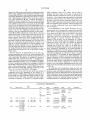
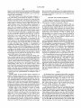
VIDEO
CDPROCESSOR
30
VIDEO
GRABBER
33
1
TI
31
34010
I
+16
MEMORY
lllllllllllllll
BANK, BANK-1 BANl<3 BANK4 BANKS BANK, BANK7 BANKa
FL;
50 I16 BITS OF DATA)
JPEG COMPRESSION
[CHIP = 35 MHz)
5,577,190
Page 2
U.S. PATENT DOCUMENTS
OTHER PUBLICATIONS
4,574,351
3/1986 Dang et a1.
364/200
4,599,689
7/1986 Berman .................. ..
364/200
1991 Symposium on VLSI Circling, p11 33~34_
4,672,441
6/1987 Hoelzlwimmer et a1.
358/135
“Adaptive Transform Coding of HDTV pictures,” Chang
4,704,628 11/1987 Chen et a1. ............ ..
358/136
lou et 31” signal Processing of HDTV’ PIOQ of the Second
381/36
Int. Workshop on Signal Processing of HDTV, L’Aquila,
477947739 11/1987 Turner 6‘ a1- -
13211323 311323 Ferre
121111215?11-113111311133111:
e1. ..... ..
322/133
“A JPEG Still Picture Compression LS1,” Tsugio Noda et a1.,
“An 96099966999119
2’
Set for the MPEG video Stan
4:785:349 11/1988 Keith et a1.
358/136
daId’”I°m.r°Tanmam eta1".IEEEIntemat.1°nal Conference
4,797,742 1/1989 Sugiyama et a1.
358/141
gglAgog/igrcsbsgpzeech 361151 561331 Processmg! ICASSP-gl
III gig/i131
“An Experimental Digital VCR with 40 mm Drum, single
.
.
12111331 51323 2312118111 .111
4,839,724
4,890,161
4,897,855
6/19g9 Keesen et a1_
12/19g9 Kondo _____ ,_
1/1990
Acarnpora . . . . .
.
,
.
,
pp.
—
.
35g/133
Actuator and DCT—Based Bit-Rate Reduction,” S. M. C.
353/135
Borgers et al., IEEE Trans. on Consumer Electronics, vol.
. . . . .. 375/27
4,937,685 6/1990 Barker et a1.
.. 360/141
4,951,139 8/1990 Hamilton et a1. ..................... .. 358/135
4,962,463 10/1990 Crossno et 81. ....................... .. 364/518
34, No. 3, 1988.
“C—Cube CL550TM Compression Monitor User’s Manual,”
Version 3.1, A Compression/Decompression Utility for Use
with [he C—Cube, CL550 Development Board, C-Cub6
Microsystems, Aug 1991, pp_ 1.13,
4,982,282
1/1991 Saito et a1. ...... ..
358/133
4,985,766
1/1991 Morrison et a1. .
358/133
“C__Cube CLSSOTM A Development Board for NuBuSTM’”
4’988’982
H1991 Rayner 6‘ a1"
340/706
C—Cube Microsystems, Oct. 1990, Product Literature.
5,046,119
9/1991 Ho?ert et a1.
n 382/56
I()II:C1u_b9e3M1croSystems, Preliminary Data Book, Aug. 1991,
.. 341/76
353/403
Mlcrosystems’ 1990
“CD—I Fu1l—Motion Video Encoding On a Parallel Com
“C—Cube 'CL550 JPEG Image Compression Processor”,
gzijzritegflluw
5,061,924 10/1991 Mailhot
1068’745 11/1991 Shimum _
“C—Cube Microsystems Compression Workshop,” C—Cube
5,()73,321 12/1991 Juri
353/135
puter,” F. Sijsterrnans and J. van der Meer, Communications
5,107,345
358/136
of the ACM, v01. 34, No. 4, Apr. 1991, pp. 82—91.
4/1992 Lee ..................... ..
5,122,875
6/1992 Raychaudhuri et a1.
358/133
“CenterStage Application Environment,” Advertising mate
5,130,797
7/1992 Murakami et a1. ..... ..
358/133
rial, Fluent Machines 1110.
5,133,459 3/1992 Roberts @1111
353/209
5,146,564 9/1992 Evans et a1. .......................... .. 395/250
5,164,980 11/1992 BUSil $1 31. .............................. .. 379/53
“CL550 Engineering Samples (BS2 Revision) Bug List,”
2138321 131333 18312"; '
iii/ii?
Literature’ NO“ 199°
5,179,651
1/1993 Taaife et'al. .... ..
395/154
niccljflfogeference swam’ Ocuba Mlcrosystems Tech'
5,193,002
5,196,933
5,202,760
5,228,028
3/1993
3/1993
411993
7/1993
Guichard et a1. ..................... .. 358/133
Henot .................................... .. 358/136
Toumer et a1_
353/141
Cucchi et a1.
.. 370/941
MiCIOSYStBmS, Preliminary Data 300k’ Feb- 1990’ PP- 1—36
“Coding of Color Television Signals Using a Modi?ed
M*Transform for 34 Mbit/s-Transmission”, Keesen et a1.,
Frequenz, vol. 38, No. 10, Oct. 1984, with translation, pp.
C_Cube Microsystems, product Marketing, Feb“ 1991_
“CLSSO Errata Information,” C_Cube Product Marketing
“CL550A JPEG Image Compression Processor”, C—Cube
5,228,126 7/1993 Marianetti,11
5,237,675 3/ 1993 Harmon, Jr
5,253,078 10/1993 Balkanski ........ ..
395/162
238-243.
395/425
Leonard, M., “1C Executes Still-Picture Compression Algo
358/426
rithms,” Electronic Design’ May 237 1991, pp. 49_53'
3215321963181
Guglielmo, Connie, “New Video Will bring IBM—endorsed
5:287:420
2/1994 Barrett .................................. .. 382/233
5,301,242
4/1994 Gonzales et a1. .
. 382/56
"4 “39 P- 5
5,309,528
5/1994 Rosen et a1. .... ..
. 382/58
Wallace, Gregory K» ‘The JPEG Still Picture Compression
5,329,616 7/1994 Silvcrbrook ..... ..
5,341,318 8/1994 Balkanski et a1.
5,369,505 11/1994 wamanabe 9‘ al-
395/164
364/725
358/444
Standard,” Communications of the ACM, Apr. 1991, v34 n4
p.30(15).
News Release entitled “Media 100TM—Indust1y’s First
gr“: et a1‘
5/1995 lacyolllis 6121."?..................... .11.‘. 395/23
Online, Nonlinear Video Production System Introduced by
Data Translation’s Multimedia Group” dated J‘m' 11’ 1992"
5:414:796
“Multimedia Group Strategy and Media 100TM Back
grounder” dated Feb. 1992.
“Announcing a totally new concept in the ?eld of video post
FOREIGN PATENT DOCUMENTS
0347330A1 12/1989
O469835A2 5/1992
European Pat. Off. .
European Pat. Off.
DVI Vldeo Tech' to Mac ‘ism’ Macweek’ Nov‘ 13’ 1990’
G06F 15/64
production” allegedly distributed Jan. 1992.
Us. Serial NO_ 08/048,458
2597282
10/198'7
3940554111
2104180
6/1990
4/1990
France .
Germany.
Japan ........................... .. H04N 7/133
U'S‘ _Sena1_N°' 08/048782‘
_
, _
C- Blrkmalen “VIdBO Compresswn, welghmg the advan
-
w091/14339
9/1991
wIPO _
tages of scalable digital video”, Videography, Jun. 1991, pp.
WO92/22166
12/1992
WIPO .... .................... .. H04N 1/415
38—50.
5,577,190
Page 3
“Combined Source Channel Coding in Adaptive Transform
Coding Systems for Images,” Goetze, M., Proceedings of
the IEEE International Conference on Communications,
May 1984, vol. 1, pp. 511-515.
“Compression Monitor Software (Version 2.0) User’s
Manual,” C-Cube Microsystems, pp. l-ll.
“Compressor/DEcompressor (CODEC),” Advertising Lit
erature, Fluent Machines Inc.
“DigiCipherTM—All Digital, Channel Compatible, HDTV
Broadcast System,” W. Paik, IEEE Trans. on Broadcasting,
vol. 36, No. 4, Dec. 1990.
“Digital Pictures, Representation and Compression,” A. N.
Netravali and B. G. Haskell, Plenum Press, New York, Jun.,
1989, pp. 301-551.
“Feature Sets for Interactive Images,” A. Lippman, Com
munications of the ACM, vol. 34, No. 4, Apr. 1991, pp.
93-102.
“Fluent Multimedia: Extending the Capabilities of DVI,”
Advertising material, Fluent Machines Inc.
“New Video will bring IBM-endorsed DVI video technol
ogy to Mac users,” C. Guglielmo, MacWEEK, vol. 4 No.39,
p. 5, Nov. 13, 1990.
“NeXTstep: Putting JPEG to Multiple Uses,” G. Cockroft
and L. Hourvitz, Communications of the ACM Apr. 1991,
vol. 34, No. 4, pp. 45 and 116.
“OBRAZ 1/ Caractéristiques Générales,” Advertising mate
rial, MACSYS (with translation).
“OBRAZ Explication succincte,” Advertising material,
MACSYS (with translation).
“Overview of the px64 kbit/s Video Coding Standard,” M.
Liou, Communications of the ACM, vol. 34, No. 4, Apr.
1991, pp. 60-63.
Proceedings of the 1983 International Zurich Seminar on
Digital Communications, Lohscheller, H., Mar. 1984, pp.
25-31.
Technical Notes Mar. 1990, C-Cube Microsystems, 1990.
“FM/l Multimedia Development System,” Advertising
“The C-Cube CL550 JPEG Image Compression Processor,”
S. C. Purcell, IEEE Computer Society International Confer
material, Fluent Machines Inc.
“IC801 Single-Chip Px64 Codec For Video Phones,” Pre
ence, 1991, pp. 318-323.
liminary Information, InfoChip Systems Incorporated, Mar.
G. K., Communications of the ACM, vol. 34, No. 4, pp.
1992, pp. 1-12.
“Image Coding by Adaptive Block Quantization,” Tasto et
al., IEEE Transactions on Communications Technology, vol.
COM-19, No. 6, Dec. 1971, pp. 957-972.
“Interframe Adaptive Data Compression Techniques for
Images,” J. R. Jain & A. K. Jain, Signal and Image Pro
cessing Lab., Dept. of Electrical and Computer Eng, Univ.
of California, Davis, Aug. 1979, pp. l-l77.
“L64735 Discrete Cosine Transform Processor,” LSI Logic
Corporation, Jan. 1991.
“L64745 JPEG Coder,” LSI Logic Corporation, Jan. 14,
1991, pp. 1-14.
“The JPEG Still Picture Compression Standard,” Wallace,
30-44, Apr. 1991.
“Toward an Open Environment for Digital Video,” M.
Liebhold and E. M. Hoifert, Communications of the ACM,
vol. 34, No. 4, Apr. 1991, pp. 104-112.
“Video Compression Chip Set,” LSI Logic Corporation, pp.
l-l6.
“Video Compression Chipset Attacks High Multimedia
Price Tags,” LSI Logic Corporation.
“Monolithic Circuits Expedite Desktop Video,” D. Pryce,
Electrical Design News, vol. 36, No. 22, Oct. 1991, Newton,
MA, pp. 67, 69, 74 and 76.
US. Patent
Nov. 19, 1996
5,577,190
Sheet 1 0f 10
SPEAKERS, 16
24
KEYBOARD
22
SEE‘
[3%
MECHANICAL
USER
iNTERFACE
20
/
DISC STORAGE
l
COMPUTER
'
I
SOURCE
Fig. 1 '
US. Patent
Nov. 19, 1996
5,577,190
Sheet 2 0f 10
x
VIDEO COPROCESSOR
VIDEO
FRAME
GRABBER
ANALOG
VIDEO
INPUT
/29
/30 -
TI
34010
MEMORY
64 BITS
A
r
lJ33
4—--—><~—--><——><-—>
BANK1BANK2 BANK3 BANK4
\\//
-)
5O MHZ CLOCK
/
V
50 (INCLUDING I6 BITS DATAI
V
JPEG COMPRESSION
(CHIP = 25 MHZ)
Fig. 2A
(Prior Art)
I32
US. Patent
Nov. 19, 1996
Sheet 3 0f 10
5,577,190
ANALOG
VIDEO
mpur
K
29
x
VIDEO
COPROCESSOR
30
f
VIDEO
FRAME
GRABBER
Tl / 31
34010
as
,J
/16
MEMORY
’
IIIIIlIIllIIIII
‘BANK; ‘BANKg‘BANKg‘BANKg ‘BANKg‘BANKré‘ BANK’; BANE8
\
J
70 MHz
/’50 (16 BITS OF DATA)
V
JPEG COMPRESSION
(CHIP = 35 MHZ)
Fig. 2B
I32
US. Patent
Nov. 19, 1996
5,577,190
Sheet 4 0f 10
a: MOTION EFFECT PARAMETERS
I — E] VARIABLE SPEED
CURRENT NEW
DURATION
RATE
34
34
\EIFTITO FILL
E FRAMES
E FPS
w % FPS
@ /I/- 34
m
STROBE MOTION —-——-—-—
a UPDATE EVERY
/36
E
-
FRAMES
@1
TARGET DISK: [E
Fig. 3
46
' /
“Es: TRANSITION EFFECT
mm E
f 44
DURATION @FRAMEs
POSITION
STARTS E
STARTING
FRAMES
AT BEFORE
‘
TRANSIT-‘C
'
- -v
TARGET DISK; MEDIA OF ROB
@
Fig. 4A
“Em TRANSITION EFFECT
EFFEcT E:
v Q FORWARD
<- REVERSE
DURATION [ILIFRMAES
POSITION CENTERED ON TRANSITION
STARTS @} FRAMES BEFORE TRANSITION
TARGET DISK: MEDIA OF ROB
LE1
Fig. 4B
US. Patent
Nov. 19, 1996
Sheet 5 0f 10
M050 1
Q WAVEFORM MONITOR
{VIDEO I‘
Qv>
SCPHASEINV
SCPHASE
Io
OUTPUTSETUP
E! VECTOR scope
5,577,190
US. Patent
Nov. 19, 1996
Sheet 6 of 10
5,577,190
F
$5
@$5+l
2Q58
“5:“5use:
um
m
E
Q
$
mm
.1
I»
M
I.
a
g
m.BAA
vv
.vn
Y1
n
u
ya
A
__v
A:
v
A
z
2
3
@
>
E
9:
o
z
w
a
h
>
3
_
n.
_
,
B
6056
<
m
=
I
D
A
v.
o
ZNBE
v“
imayQ2S9E528%0
.x.
Tr
g
m
"
A
vv
v
_
N
n
q
m
o
Q
Ema
"
5%
N
x
u
>
m
z
2
EIW
.@EE
0
\NN
1>
f a
L
US. Patent
Nov. 19, 1996
Sheet 7 of 10
5,577,190
24
52
7
Fly.
582
US. Patent
Nov. 19, 1996
Sheet 8 of 10
COMPRESSION
5,577,190
/ 212
PROCESSOR
DM A PORT
r. __ ...
I
COMPRESSION
PROCESSOR \
I
‘
2,20
_ __'
DMA AOOR. REG.
|
DMA LIMIT REG.
COMPRESSED
DATA
BUFFER
' 2,4
;
222
I
REGISTER
ACCESSES
L-
I
4 DMA PORT
/
224
BUS.
HOST COMPUTER
c PU
MEMORY
W216
1
SCSI PORT
Fig.9
US. Patent
Nov. 19, 1996
Sheet 9 of 10
VIDEO IN
5,577,190
VIDEQ OUT
IMAGE DIGITIZER
*‘ZIO
I
_,2l2
COMPRESSION PROCESSOR
f
COMPRESSED DATA BUFFER
HOST COMPUTER
F'g- 8
I
STORAGE “'"ZIB
k2|4
M216
US. Patent
Nov. 19, 1996
Sheet 10 of 10
5,577,190
R‘ G’ B
R} G, B
IMAGE DATA
IMAG? DATA
SOURCE
RECONSTRUCTED
IMAGE
IMAGE
DATAIY,u, and v)
DATA
FDCT
IDCT
Ac
Dc 2' AC2
\ X‘
QUANTIZER
Dc
Ac
‘H
A-
263
-
' AC1
)
DEQUANTIZER
Ac‘z
l
ENOTROPY
ENTROPY
ENCODER
DECODER
COMPRESSED
COMPRESSED
IMAGE
DATA
IMAGE
DATA
Fig.ll
5,577,190
1
2
MEDIA EDITING SYSTEM WITH
ADJUSTABLE SOURCE MATERIAL
COIVIPRESSION
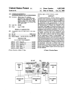
exhaustive qualitative tests and careful study, the JPEG
group picked the DCT approach, and also de?ned in detail
the various ways this approach could be used for image
compression. The group published a proposed ISO standard
RELATED APPLICATIONS
that is generally referred to as the JPEG standard. This
standard is now in its ?nal form, and is awaiting rati?cation
This application is a continuation-in-part of U.S. patent
application Ser. No. 07/807,269 entitled “Buffer and Frame
Indexing”, now U.S. Pat. No. 5,513,375 U.S. patent appli
cation Ser. No. 07/807,117 entitled “Quantization Table
Adjustment”, both to Eric C. Peters and ?led on Dec. 13,
1991, and a continuation of U.S. patent application Ser. No.
by ISO, which is expected.
The JPEG standard has wide implications for image
capture and storage, image transmission, and image play
10
back. A color photograph can be compressed by 10 to l with
virtually no visible loss of quality. Compression of 30 to 1
can be achieved with loss that is so minimal that most people
cannot see the difference. Compression factors of 100 to l
07/866,829 entitled “Media Composer With Adjustable
Source Material Compression”, ?led on Apr. 10, 1992, now
U.S. Pat. No. 5,355,450.
and more can be achieved while maintaining image quality
BACKGROUND OF THE INVENTION
of important hardware developments. The DCT algorithm
used by the JPEG standard is extremely complex. It requires
acceptable for a wide range of purposes.
The creation of the JPEG standard has spurred a variety
This invention relates to hardware designs coupled with
software-based algorithms for capture, compression, decom
pression, and playback of digital image sequences, particu
larly in an editing environment.
Video and audio source material editing systems employ
ing digital techniques have been introduced over the last
several years. One example is the Avid/1 Media Composer
from Avid Technology, Inc., of Burlington, Mass. This
media composer receives, digitizes, stores and edits video
20
25
converting an image from the spatial domain to the fre
quency domain, the quantization of the various frequency
components, followed by Huffman coding of the resulting
components. The conversion from spatial to frequency
domain, the quantization, and the Huffman coding are all
computationally intensive. Hardware vendors have
responded by building specialized integrated circuits to
implement the JPEG algorithm.
One vendor, C-Cube of San Jose, Calif., has created a
JPEG chip (the CL550B) that not only implements the JPEG
and audio source material After the source material is
digitized and stored, a computer such as an Apple Macintosh
standard in hardware, but can process an image with a
based computer manipulates the stored digital material and
resolution of, for example, 720x488 pixels (CCIRR 601
a pair of CRT monitors are used for displaying manipulated
30
material and control information to allow editing to be
performed. Later versions of the media composer included
video standard) in just 1/3oth of a second. This means that the
JPEG algorithm can be applied to a digitized video
sequence, and the resulting compressed data can be stored
for later playback. The same chip can be used to compress
compression techniques to permit the display of full motion
or decompress images or image sequences. The availability
of this JPEG chip has spurred computer vendors and system
integrators to design new products that incorporate the JPEG
chip for motion video. However, the implementation of the
video from the digitized source material. Compression was
achieved using a JPEG chip from C-Cube of Milpitas, Calif.
That data compression is described more fully below.
Although previous media composers could achieve full
motion video from digitized sources, the compression
chip in a hardware and software environment capable of
processing images with a resolution of 640x480 pixels or
degraded image quality below desirable levels. Further, the
media composer lacked features which enhance the editing
greater at a rate of 30 frames per second in an editing
process.
environment introduces multiple problems.
The idea of taking motion video, digitizing it, compress
For high quality images, a data size of 15-40 Kbytes per
frame is needed for images at 720x488 resolution. This
ing the digital datastream, and storing it on some kind of
media for later playback is not new. RCA’s Sarnoff labs 45 means that 30 frames per second video will have a data rate
of 450 to 1200 Kbytes per second. For data coming from a
seeking to create a digital rather than an analog approach.
disk storage device, this is a high data rate, requiring careful
This technology has since become known as Digital Video
attention to insure a working system.
began working on this in the early days of the video disk,
Interactive (DVI).
Another group, led by Phillips in Europe, has also worked
The most common approach in prior systems for sending
50
on a digital motion video approach for a product they call
CDI (Compact Disk Interactive). Both DVI and CD1 seek to
store motion video and sound on CD-ROM disks for play
back in low cost players. In the case of DVI, the compres
sion is done in batch mode, and takes a long time, but the
playback hardware is low cost. CDI is less speci?c about the
data from disk into the memory of the host computer, and
then to send the data to the compression processor. In this
method, the computer memory acts as a buffer against the
different data rates of the compression processor and the
disk. This scheme has two drawbacks. First, the data is
moved twice, once from the disk to the host memory, and
another time from the host memory to the compression
processor. For a data rate of 1200 Kbytes per second, this
can seriously tax the host computer, allowing it to do little
compression approach, and mainly provides a format for the
data to be stored on the disk.
A few years ago, a standards-making body known as
CCIIT, based in France, working in conjunction with ISO,
60
the International Standards Organization, created a working
group to focus on image compression. This group, called the
copy data to the compression processor at the same time.
years to determine the most effective way to compress
schemes, including vector quantization (the technique used
by DVD and DCT (Discrete Cosine Transform). After
else but the data copying. Furthermore, the Macintosh
computer, for example, cannot read data from the disk and
The present invention provides a compressed data buffer
speci?cally designed so that data can be sent directly from
Joint Photographic Experts Group (JPEG) met for many
digital images. They evaluated a wide range of compression
data from a disk to a compression processor is to copy the
65
the disk to the
With the JPEG algorithm, as with many compression
algorithms, the amount of data that results from compressing
5,577,190
3
4
an image depends on the image itself. An image of a lone
seagull against a blue sky will take much less data than a
space of the host computer bus. The data sequence is
unloaded from the storage device into the data buffer, which
is twice mapped into the address space of the host computer.
cityscape of brick buildings with lots of detail. Therefore, it
becomes di?icult to know where a frame starts within a data
?le that contains a sequence of frames, such as a digitized
In a further aspect, the invention relates to an apparatus
and method for adjusting the post decompression quality of
a compressed image. The image quality adjustment is per
formed by constructing a quantization table that speci?es the
high frequency image components to be ?ltered, and by
subsequently ?ltering out those components speci?ed by the
and compressed sequence of video. This creates particular
problems in the playback from many ?les based on edit
decisions. With ?xed size compression approaches, one can
simply index directly into the ?le by multiplying the frame
number by the frame size, which results in the offset needed
10
to start reading the desired frame. When the frame size
varies, this simple multiplication approach no longer works.
BRIEF DESCRIPTION OF THE DRAWINGS
One needs to have an index that stores the offset for each
frame. Creating this index can be time consuming. The
present invention provides an ef?cient indexing method.
It is often desirable to vary the quality of an image during
compression in order to optimize the degree of data com
pression. For example, during some portions of a sequence,
detail may not be important, and quality can be sacri?ced by
compressing the data to a greater degree. Other portions may
require greater quality, and hence this greater degree of
compression may be unsuitable. In prior implementations of
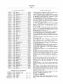
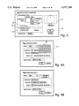
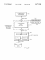
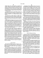
FIG. 1 is a schematic diagram of the media composer
system.
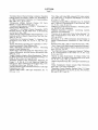
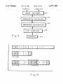
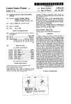
FIG. 2a is a prior art video compression con?guration.
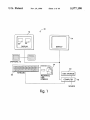
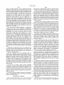
FIG. 2b is the video compression con?guration according
to the present invention.
20
capture instrumentation.
25
they must be correspondingly m-scaled during decompres
sion in order to obtain a suitable image. This re-scaling is
cumbersome to implement and can cause delays during
playback. According to one aspect, the present invention is
FIG. 9 is a schematic diagram of a compressed data bu?’er
according to one embodiment of the invention.
FIG. 10 is a schematic illustration of an edited sequence
to enable optimum data compression for all portions of a
sequence, while allowing playback with a single quantiza
tion table.
35
SUMMARY OF THE INVENTION
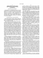
FIG. 11 is a schematic illustration of data compression
DESCRIPTION OF THE PREFERRED
EMBODIMENT
45
back.
20 communicates with the computer 18. Disk storage 20
50
55
by the system 10, digitized and stored in the disk storage
device 20. The computer 18 is programmed so that the
digitized source material may be edited and displayed on
one of the video display devices such as the CRT display 12.
Typically digitized source material would be displayed at a
instrumentation. The system also enables sync point editing
and slip sync. The system also provides for a novel mechani
cal user interface including a track ball and speed control
integrated into a single unit. Importantly, the system also
includes one to seven disks for media storage. The disks may
be optical or magnetic. The system 10 is controlled by a
keyboard 22 and a mechanical user interface 24 to be
described in more detail herein.
In operation, video and audio source material is received
speed eifects, ?t-to-?ll capability, and strobe motion. The
change audio scrub, graphics positioning and image capture
With reference to FIG. 1 the media composer system 10
includes a pair of CRT displays 12 and 14 and an audio
output device 16 which may include two speakers. The
video displays 12 and 14 and the audio transducer 16 are
controlled by a computer 18. It is preferred that the computer
18 be a Macintosh from Apple Computer Corporation des—
ignated as H,,, Ila, Hfx or Quadra 900. Disk storage apparatus
whose rotation rate corresponds to a selected motion effect
rate. Motion effects include forward and reverse variable
improved media composer of the invention enables a variety
of wipes to be effected, zoom to full screen capability, pitch
of images along with two mapping schemes of the com
pressed data bu?er in the host system’s bus.
and decompression according to the IPEG algorithm.
The media composer according to the invention for edit
In another aspect of the invention, the computing appa
ratus is programmed to provide motion effects in the dis
played material and is further programmed to provide a dial
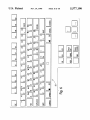
FIG. 6 is an illustration of a keyboard layout.
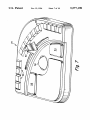
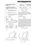
FIG. 7 is a perspective view of the mechanical user
interface according to the invention.
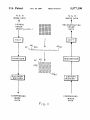
FIG. 8 is a block diagram of a video image capture and
playback system implementing data compression.
a method that allows for quality changes during compression
ing source material includes apparatus for receiving, digi
tizing, storing and editing video and audio source material.
Computing apparatus manipulates the stored source material
and output apparatus communicates with the computing
apparatus for displaying the manipulated material and con
trol information. The computing apparatus includes JPEG
compression apparatus and is programmed so that multiple
JPEG resolutions can be displayed, recorded and played
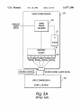
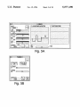
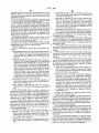
FIG. 3 is a schematic view of the motion effects screen.
FIGS. 4a and 4b are schematic illustrations of the tran
sition effects screen.
FIGS. 5a and 5b are schematic illustrations of image
the JPEG algorithm, quality is adjusted by scaling the
elements of a quantization table (discussed in detail herein
below). If these elements are scaled during compression,
table.
60
location 26 and edited material at a location 28 on the
supports a media consolidation process to free up disk space.
display 12.
The data buffer of the invention compensates for the data
rate differences between a storage device and the data
As will be appreciated by those skilled in the art, repro
ducing full motion, 30 frames per second color video from
compression processor of a digital image compression and
playback unit. The data buffer interfaces to a host central
processing unit, a storage device, a DMA address register,
and a DMA limit register, and is mapped into the address
a digital source is a daunting task. FIG. 2a illustrates a prior
65
art system for providing digitization and compression of
video images. This system includes a video coprocessor 29,
such as the NuVista board made by TrueVision of India
5,577,190
5
6
napolis, Ind. Many other commercially available boards may
which multiplies values in the tables, may be used to
also be used. A suitable video coprocessor includes a video
designate and scale values in this table. A high Q factor
provides increased compression typically at the expense of
resolution. A low Q factor improves resolution but typically
increases compressed frame size. With most systems, if the
Q factor is too low, and the compressed frame size is too
high, the JPEG compression chip cannot compress incoming
data at an adequate speed. Typically, when this happens, the
frame grabber 30 which converts analog video information
into digital information, representing each pixel of a frame
with a predetermined number of bits, in this case l6-bits.
The video coprocessor 29 has a memory 33 which is
con?gured using a coprocessor 31, such as the T134010
made by Texas Instruments, to provide an output data path
to feed JPEG circuitry, such as is available as chip CLSSOB
from C-Cube of Milpitas, Calif. Such con?guration can be
performed using techniques known in the art. In the system
of FIG. 2a, the output data path is 64 bits, divided into four
banks of 16 bits. Two signi?cant limitations exist in this
situation. First the connection path between a video copro
cessor 30 and JPEG compression circuitry 32 was a 50-wire
design allowing only 16 bits to pass at one time (16 wires for
10
15
inability to process 640><480><24 (or 32) bit images at 60
?elds per second. Typically users of the JPEG chip (c3
CL550B chip) dealt with this by either shrinking the size of
the image, reducing the bits per pixel information, or slow
ing the ?elds per second rate. All of this results in lower
tables changed, to increase resolution. The decrease or
20
time, that the same table be used. As an alternative to
decreased for the highest frequencies ?rst, and eventually for
25
30
video coprocessor 29, however, is con?gured to provide a
128-bit data path, wherein each pixel is represented by
24-bits. The connection between the coprocessor 29 and the
JPEG compression circuitry is run at 70 MHZ. The JPEG
circuitry is programmed using known techniques to indicate
increase of the Q factor may be performed in a binary,
step-wise or other suitable manner. Changing the Q factor
changes all values in the table, and requires, at playback
changing the Q factor, the values in the table can be
quality video.
FIG. 2b illustrates an improvement over the prior art.
Similar components are used for the video coprocessor 29
and JPEG compression circuitry 32. The memory 33 of the
below. When it is determined that the compressed frame size
is too large, the Q factor may be increased, or the tables
frame size is small, the Q factor may be decreased, or the
16-bit connection) was driven by a 50 MHZ clock which
governed its speed to match adequately the 16-bit per cycle
must be selected.
In an embodiment of the present invention, the com
pressed frame size is monitored in a manner to be described
adjusted, automatically. Conversely, if the compressed
data; 16 for control of data; others for synchronizing and
system control). Second, the JPEG circuitry 32 (and the
flow. The combination of these limitations resulted in an
user is noti?ed, compression stops and a higher Q factor
35
that 24-bits of input data is used to represent a pixel. The net
effect of these improvements is that the JPEG chip is run
faster and receives more data, allowing compression of 60
frames per second of 640X480><24 (32) images.
The use of a 24-bit word for each pixel may increase
compressed frame size depending on the content of a
particular frame. A JPEG chip is con?gured for compression
by providing two 8X8 quantization tables, which are well
known in the art. The values are placed into these tables
according to frequency. A “Q factor,” a composite number
lower frequencies, depending on the desired increase or
decrease in compression. For this purpose, a table may be
maintained to relate a percentage of disparity between actual
and desired compression to a number of values in the table
to be decreased. If, for example, an actual compression of
22K bytes/frame is achieved when 20K bytes/frame was
desired, a disparity of 10% is obtained. From this table, the
number of frequencies to be decreased can be determined.
The change can be made in a manner known to those of skill
in this art. This dynamic adjustment, or roll-off, is not
limited to use with systems representing pixels with 24-bit
words. It may be used with other systems, such as the system
of FIG. 2a.
The monitoring of the compression frame size will now
be described. For this purpose, the coprocessor 31 is pro
grammed, using well-known techniques, so that, at the end
of each frame received, eight black lines are provided to the
JPEG compression circuit. It then issues an interrupt signal,
which is received by the host computer. By the time the host
computer receives the interrupt signal, all data from the
compressed frame is compressed and the only data
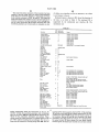
Hardware Matrix (PRELIMINARY)
Res.
Depth Audio
Max
K/f
CPU
IPEG
Audio HW
Disks
Atto
[Ix
JPEG I
AudioMedia
Panasonic
Without
Opticals
IIci
JPEG Il
SA-4 & VSD
600 MB
With
or Pro I/O
IIfx
VRl
24 bit 2 x 22 kHz
7
320 x 240
JPEG HI
1 GB
Quadra 900
1.5 GB
11x
JPEG I
5400 RPM
Panasonic
AudioMedia
Without
Opticals
VR2
VR3
24 bit 2 x 44 kHz
24 bit 2 x 48 kHz
(one disk)
4 x 48 kl-Iz
VR4
24 bit 2 X 48 kHz
12
18
320 x 240
640 x 240
Ilx
IIx
JPEG I
JPEG l
AudioMedia
SA-4 & VSD
or Pro I/O
600 MB
600 MB
Without
Without
23
640 X 240
Hfx
JPEG Il
SA-4 & VSD
1 GB
With
or Pro l/O
(600 MB?)
(sep. disks)
(one disk)
4 X 48 kHz
(sep. disks)
Comments
5,577,190
7
8
-continued
Hardware Matrix (PRELIMINARY)
Res.
Depth Audio
VR5
24 bit 4 X 48 kHz
Max
K/f
40
640 X 240
CPU
JPEG
llfx
JPEG II
Audio HW
Disks
Alto
SA-4 8:. VSD
5400 RPM
With
5400 RPM
With
Comments
or Pro V0
VR21
16 bit 4 X 48 kHz
20 X 2 640 X 240 x 2
Quadra 900
JPEG II
SA-4 & VSD
or Pro 1/0
24 bit
Not for release in 4.0
VR6
4 X 48 kHz
VR22
4 X 48 kHz
Maybe
not 4.0
JPEG HI
60
640 X 240
30 X 2 640 X 240 X 2
Quadra 900
(llfx?)
Quadra 900
JPEG III
JPEG Ill
SA~4 & VSD
or Pro I/O
SA-4 & VSD
5400 RPM
With
Not for 4.0
5400 RPM
With
Not for 4.0
or Pro I/O
remaining in the pipeline in the JPEG circuit are the extra
black lines. Since part of the J PEG standard includes placing
a marker at the beginning of the frame, the length of the
compressed frame may be readily determined. Although the
extra black lines become part of the compressed image, they
are readily removed upon decompression and playback, by
removing the last eight lines of each decompressed frame.
Table 1 illustrates the various hardware con?gurations for
achieving different levels of resolution. In the table, JPEG IH
refers to the con?guration shown in FIG. 2b.
The improved media composer of the invention allows the
20
The ?t-to-?ll option allows one to have the media com
25
user to pro-visualize motion effects by creating clips and
media ?les which display the requested effect. The new clip
poser calculate the motion e?’ect required to ?ll a speci?c
duration in a sequence with a speci?c duration from the
source. The ?t-to-?ll check box 38 is hold only when the
operator has marked an IN and OUT in both monitors 26 and
28 or the four marks are implied by the location of the
position control. Given these values for the source (current)
and target (new) durations, the media composer calculates
the necessary rate in percent speed of the motion e?ect. One
can be used like any other chip-it can be trimmed,
extracted, overwritten, used in dissolves and wipes, etc.
motion, it creates a clip in which some portion of the source
frames have been deleted. When these clips are played, the
motion may appear jerky since the media composer is not
synthesizing a smoothed series of frames. This effect is
especially likely with material transferred from ?lm.
30
may accept these or enter one’s own values. Once the media
composer has created a new clip, one can overwrite or splice
it into the sequence.
Strobe motion is a type of motion effect in which one
hour regardless of the time code of the original clip. Motion
frame is held for a speci?c duration and then the next for the
effects can be created from master clips and subclips, but not 35 same duration and so on. When one opens a clip in the
from other motion effect clips. There is a delay as the media
source monitor, mark an IN and an OUT, and select strobe
composer creates new media ?les. Motion effects are orga
motion 40 in the motion e?ects dialog box. The operator
nized into three related features: variable speed, ?t-to-?ll,
must ?ll in the n in “update every 11 frames” 42. The new clip
and strobe motion. These features are accessed through a
will have the same duration as the current one but only every
single command in a source menu. A Motion E?cects com
nth frame is displayed. A Remake Effects command recre
and its media can be manipulated as any other, that is, it can
be deleted, consolidated, and even back digitized. The new
motion effect clips are video only. The start time code is zero
mand opens a dialog box illustrated in FIG. 3. A preview dial
34 allows the operator to pre-visualize the effect even before
the OK function 36 is clicked on. The dial 34 nonnally
rotates at one revolution per second. When the operator
enters values for an effect and clicks on PREVIEW, the dial
rotates at the new appropriate speed. In this way, the preview
45
dial works as a metronome to give the operator a feel for the
pace or rhythm of the effect.
Forward and reverse variable speed effects will now be
discussed. First of all, the operator opens a clip in the source
monitor 12 and marks an IN and an OUT, and chooses
motion eifects from the monitor 14 command menu. The
operator then enters any one of three parameters: duration,
play rate (in fps), or percent speed. When any one of these
parameters is entered, the media composer immediately
ates dissolve media ?les and includes all motion e?fects. As
with transition effects it is only possible to recreate motion
e?fect media ?les when the original source media is online.
When the operator batch digitizes a sequence which includes
motion effects, the effects are automatically recreated at the
end of the process. Motion effects are represented correctly
. in all supported edit decision list (EDL) formats with the
following caveat: It may not be possible to express accu
rately the media composer motion effect in an EDL because
the format may limit the precision with which percent speed
55
calculates and displays the values for the other two param
can be expressed to whole numbers or one decimal place and
the media composer is not likewise limited. In this case, the
media composer appropriately truncates the rate or percent
speed in the EDL and generates a comment which indicates
the true rate or percent speed. With the exception of freeze
frames, motion effects are ignored by auto-assembly. Auto
assembly edits video from an original clip at 30 frames per
second, starting at the edit inpoint and ?lling the duration of
eters. For example, if one marks a one second piece and
enters 50% fps, the media composer will immediately show
two seconds as the duration and 15 fps as the play rate of the
the effect.
The improved media composer will allow the operator to
new clip. One speci?es reverse motion by entering a nega
tive rate or percent speed. When the operator clicks on OK,
play four tracks of audio simultaneously instead of only two
the media composer creates a new clip and video/media ?le
as in earlier versions. The four tracks are not output through
for the appropriate effect and loads this clip into the source
monitor 12. It should be noted that when the operator asks
for slow motion, the media composer creates a clip in which
each frame is duplicated a proportionate number of times.
Similarly, when one asks the media composer for fast
four separate channels, rather only two. The operator hears
the tracks through two speakers 16 (FIG. 1) according to the
65
pan setting for each track. In addition, it is not possible to
digitize simultaneously four channels of audio. The operator
can specify which tracks are candidates to be played by
5,577,190
9
10
tagging them with speakers on an edit panel. When the
operator chooses l) to play a sequence, 2) to record a digital
the EDL Tool allows one to specify the appropriate pattern
number for each wipe pattern. The table of numbers and
cut, or 3) to auto assemble a sequence with direct audio, the
patterns is stored in a ?le which can be moved from on
audio tracks will be output through two channels according
media composer to another. It is not, however, possible to
to the pan setting for every component on each track. The
two output channels can be either analog or digital according
to the wiring of an audio interface unit. If the user selects
audio from tapes, autoassembly will execute edits for audio
channels 3 and/or 4. If the selected EDL format supports
four channels, the EDL will include edits for channels 3
and/or 4. The EDL formats which support 4 channels are
CMX 3600, Sony 9000 and GVG 4.1. In both the EDL tool
and autoassembly, the user can specify which media com
poser tracks are output as channels 1, 2, 3 and 4. One should
note that it is not possible to digitize or output four analog
save and choose among several different sets of values. The
present media composer will also allow the operator to Zoom
to full-screen mode from any monitor (source, record,
pop-up) by pressing the quote key. All keyboard equivalents
10
The media composer of the present invention allows the
operator to enter a mode in which a mouse controller can be
used as a shuttle control. Hit L to shuttle forward, Play (the
5 and Back Quote Keys) to shuttle at 30 fps, K (or click a
mouse button) to pause (zero speed), J to shuttle backward,
and the Space Bar to exit the Shuttle Mode. Hit L twice to
shuttle at 60 fps, thrice to shuttle at 90 fps. Hit J twice for
—60 and thrice for —90. While shuttling at Zero speed, either
full-screen or normal, many of the keyboard functions are
channels of audio simultaneously. However, regardless of
the software limitations, it is not possible to output four
digital channels of audio because of limitations in the audio
interface.
The media composer of the invention will allow the
operator to digitize audio at a 48 KHZ sample rate. However,
active. It is possible to step through the program, clear
marks, use both kinds of audio scrub (see below), go to the
next or previous edit, show safe titles, etc. If the media
composer cannot do the function and remain in Shuttle
it is not possible to use both 48 and 22 KHZ or 44 KHZ audio
in the same sequence. Thus, 48 KHz must be used exclu
sively when playing a sequence or batch digitizing. When
working with the audio interface and video slave driver and
48 KHZ audio is selected in the digitized selections dialog
function in full-screen mode. The one exception is that one
cannot use Trim Mode while in full~screen play.
Mode, the mode is dropped and the function performed.
25
box, the media composer automatically adjusts the sample
Toggling between source and record is an example of such
an operation. In one embodiment of the present invention,
jog shuttling may be performed, with a result which is
rate on the audio interface. However, one must manually
similar to that obtained using mechanical jog shuttle controls
switch the video slave driver from 44 to 48 KHZ. Digitizing
in connection with video tape recorders. With digitized
mixed audio allows one to save space by combining the 30 images being played, a mouse or similar input device can
material in two audio channels into a single media ?le which
provide control for jog shuttling. Jog mode begins when an
is played from both speakers 16. All other audio features,
operator pressed a button. While the button is depressed,
including crossfades, mixdown, and both types of audio
movement of the mouse in one direction or another deter
scrub, work with 48 KHZ audio. The minimum audio
hardware required to digitize 48 KHz is a SA-4 card and
mines the speed of shuttling, or of playback. That is, the
position of the mouse when the button is depressed is used
35
either the Pro 1/0 or Pro Tools. This hardware is available
as a reference position. With a relationship de?ned between
from Digidesign of Menlo Park, Calif. The media composer
position and playing speed, the further the operator moves
improves 22 KHZ audio by automatically increasing the
amplitude of low level signals.
the mouse from the reference position, the faster video is
played back in a given direction. For example, movement of
the mouse to the right increases the forward playing speed.
If the mouse is returned to the reference position, playing
stops. As the mouse is moved to the left, the reverse playing
The media composer of the invention offers wipes as a
transition effect. Wipes are accessed through a Transition
Effect command. This command opens a dialog box 44
(FIG. 4a) which allows the user to choose in a pop-up menu
between the two transition effects: dissolve and wipe. When
wipe is selected, the operator can choose a pattern from a
menu of sixteen choices 46 (displayed graphically) and a
speed increases.
An important aspect of the present media composer is a
45
direction——forward or reverse as shown in FIG. 4b. Forward
means that the outgoing clip is represented by the white in
the pattern from the menu 46 and the incoming by the black
(actually blue). Reverse means the incoming is represented
by the white. Regardless of whether the operator chooses
50
pitch change audio scrub feature. When the operator shuttles
through footage, smooth, continuous audio will be produced
at the corresponding speed. That is, pitch will vary with the
speed as with an analog tape. This feature is available for
one track only. Designate the track for smooth scrub by
option clicking (or double clicking) on the speaker icon for
that track. The icon becomes an outline. Smooth scrub is
dissolve or wipe, the duration must be entered in frames, its
available whenever the operator is shuttling, using either the
start relative to the transition (starting, centered, ending, or
mouse or the shuttle control (beneath the Play button on a
olfset) and a target drive for the media ?les.
keyboard discussed below) to determine the shuttle speed.
The effect can be viewed only after the media composer 55
When the operator imports a graphic into the media
creates a media ?le for the speci?ed wipe or dissolve. These
composer and edits it onto the G track of the sequence, it
effect ?les will be created, deleted, and recreated in exactly
may not be positioned optimally with respect to the under
lying video. When the position control is within the graphic
the same way dissolve media ?les have been in earlier
versions. The Remake Effects command includes all transi
tion eifects. As with motion effects, it is only possible to
element, you can drag the graphic to a more desirable
includes transition effects is digitized, the effects are auto 65
matically recreated at the end of the process. All wipes are
position. Option-drag is for ?ne control and control-click
will move the graphic to its original centered position.
During dragging, the media composer displays a special
window with information about the graphic’s current posi
tion relative to the center (its original position) and relative
to its position immediately before it was moved. Both of
these positions are measured in pixels along the horizontal
expressed correctly in all EDL formats. A dialog box from
and vertical axes.
60
recreate transition effect media ?les when the original source
media is online. For example, media for both the incoming
and outgoing clip must be online for the media composer to
recreate the dissolve between them. When a sequence which
5,577,190
11
12
The improved media composer of the invention has been
of sliders as an interface to allow an operator to set values
updated to provide image input and output instrumentation
in the form of a waveform monitor, a vectorscope and black
level controls as shown in FIGS. 5a and 5b. This improved
Video Tool allows the operator to save and load settings for 5
contrast, luminance, hue and saturation. Such settings con
trol the video coprocessor 29 and adjust incoming data. The
waveform generator and vectorscope are analogous to their
is well known in the art.
Keyboard layout is shown in FIG. 6 and the function of
the keys is set forth in Table 2. The keyboard 22 is
augmented by the mechanical user interface 24. The
mechanical user
TABLE 2
USB Keyboard
Function
(y/n) Equivalent
l-Frame Back
l-Frame Forward
lO-Frame Back
lO-Frame Forward
Al track on/off
A2 track on/o?‘
A3 track on/olf
A4 track on/oif
activate source/record
monitor
All Stop
Clear IN
Clear OUT
Clear Marks
Copy to Clipboard
Go to IN
Go to OUT
Go to Prev Edit
3
4
I
2
9
0
motion control
motion control
motion control
motion control
track selector
track selector
-
track selector
button
button
button
button
:
track selector
ESCAPE
moved from * on numeric keypad
SPACE BAR
D
F
G
C
Y
Y
Y
Y
Exit Mouse Shuttle
Extract
Fast Forward
Find Frame
Full Screen on/off
Notes
SPACE BAR
X
U
I
Y
Y
'
deck control function
mode toggle
Y Q
Go to Next Edit
Y
Y
Y
W
A
S
Y
Y
Z
T
Y
Y
E, I
R, 0
M
two equivalents for convenience
two equivalents for convenience
Trim Mode function-trim buttons
<
B
K
Trim Mode function-trim buttons
Graphics track on/oif
Lift
Mark Clip
Mark IN
Mark OUT
Minus 10 Frames
Minus l Frame
Overwrite
Pause
7
Y
Play
Y
5
track selector
except in Trim Mode; mouse shuttle and
deck control function
moved from Tab. The big Play button
can be con?gured as Play IN to OUT or
Play IN to OUT
Plus 1 Frame
Plus 10 Frames
Rewind
Safe Title/Action
Shuttle Back
Shuttle Forward
Y
Y
6
>
Shuttle Forward
see Play
Trim Mode function-trim buttons
/
Y
Trim Mode function—trim buttons
deck control function
1
J
L
mouse shuttle and deck control function
except in Trim Mode; mouse shuttle and
<
M
>
‘I
V
L
;
except in Trim Mode
except in Trim Mode
except in Trim Mode
except in Trim Mode
deck, control function
Slip Left (1 frame)
Slip Left (10 frames)
Y
Slip Right (1 frame)
Slip Right (10 frames)
Y
Splice
Y
Trim Both
Trim Incoming
Trim Outgoing
Video track on/o?‘
K
8
Delete Clip/Sequence
DELETE
only in Trim Mode
only in Trim Mode
only in Trim Mode
track selector
opens delete dialog box from Bin menu
(from a bin)
60
analog counterparts which are well known in the art. An
operator viewing the waveform generator and vectorscope
interface 24 is shown in more detail in FIG. 7. The interface
24 includes a track ball 50 and a speed controller 52. As with
may use the sliders 100,101, 102 and 103 to respectively set
a mouse, the track ball 50 may be used to locate a cursor on
values for hue, saturation, luminance and contrast. These
the monitors. Buttons 54 and 56 serve functions like those
provided by the click button on a mouse. It is preferred that
the speed control 52 have detents for zero speed normal
forward speed (30 frames per second) and a reverse normal
values control the video processor, in a manner known in the 65
arts which adjusts incoming data accordingly. The line of a
frame may be selected for viewing using slider 104. The use
5,577,190
13
14
speed. It is also preferred that the speed control 52 be spring
disk is removable, all the drives in the media composer can
be freed up. It is noted that the source media must be on line
for media consolidate to work since it is not going back to
loaded to return to the zero speed position. It is contemplated
that additional buttons 58 be provided so that a user may
the original tapes.
program their functionality.
Yet another aspect of the improved media composer is
sync point editing which allows the operator to specify a
BUFFER AND FRAME INDEXING
position in one monitor that is desired to be in sync with the
position in the other monitor. The operator then performs an
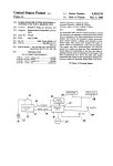
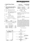
A block diagram according to a preferred embodiment of
a system for capture, compression, storage, decompression,
and playback of images is illustrated in FIG. 8.
As shown, an image digitizer (frame grabber) 210, cap
tures and digitizes the images from an analog source, such
as videotape. Image digitizer 210 may be, for example, a
overwrite that preserves that sync relationship. Sync point
editing (SPE) is accessed using the SPE command in the
media composer menu. Sync point editing is performed in
three steps. First, a point is speci?ed in the destination, or
record, clip, for example by placing a mouse cursor on the
displayed frame of the clip and pressing the mouse button.
The location within the clip is then stored. Second, a point
TrueVision NuVista+ board. However, the NuVista+ board
is preferably modi?ed and augmented with a pixel engine as
in the source material is identi?ed in a similar manner. Third,
described in “Image Digitizer Including Pixel Engine” by B.
the size of the source information is speci?ed, for example,
Joshua Rosen et al., ?led Dec. 13, 1991, to provide better
data throughput for a variety of image formats and modes of
by using IN and OUT markers. These steps may, in fact, be
performed in any order, which may be de?ned by the
programmer of the computer. After these three steps are
completed, the source information is overwritten in the
operation. Other methods of acquiring digitized video
20
destination, or record, information, by placing the identi?ed
source location at the speci?ed destination location. Such
sync point editing may be performed with any combination
of audio and video clips. Typically, it is performed to
25
synchronize recorded sound to an event in a video clip. The
operator may then turn PHANTOM marks on in the media
composer window to see how the PHANTOM marks behave
in relation to the position control in the record monitor 28.
ing to a compression algorithm. Preferably, this algorithm is
the JPEG algorithm, introduced above. As discussed above,
C-Cube produces a compression processor (CL550B) based
on the JPEG algorithm that is appropriate for use as the
compression processor 212. However, other embodiments
are within the scope of the invention. The compression
processor 212 may be a processor that implements the new
With SPE o?, the system uses the current position as the IN;
with SPE on, the current position is the sync point. It should
MPEG (Motion Picture Experts Group) algorithm, or a
processor that implements any of a variety of other image
compression algorithms known to those skilled in the art.
The compressed data from the processor 212 is preferably
be noted that one can mark the IN and OUT in the record
monitor 28 instead of the source monitor 26.
Another aspect of the invention is slip-sync editing. This
kind of editing typically refers to maintaining synchroniza
frames may be used, e.g., direct capture of digital video in
“D-l” or D-2” digital video formats.
A compression processor 212 compresses the data accord
input to a compressed data buffer 214 which is interfaced to
35
tion between a series of video clips and corresponding audio
clips when transitions between clips are trimmed. In prior art
systems, when an audio clip was trimmed, i.e., made shorter,
subsequent clips became out of synchronization with their
corresponding video clips. In the present system, when
audio material is removed from one end of an audio segment
from a clip, source material from the original audio clip is
added to the other end of the segment so as to maintain the
length of the audio segment. The source material can readily
a host computer 216 connected to a disk 218. The com
pressed data buffer 214 preferably implements a DMA
process in order to absorb speed di?erences between the
compression processor 212 and the disk 218, and further to
permit data transfer between the processor 212 and the disk
218 with a single pass through a CPU of the host computer
216. (The details of the compressed data buffer 214 accord
ing to the present invention will be presented hereinbelow.)
The host computer 216 may be, for example, an Apple
Macintosh.
be retrieved from the memory location or disk on which it 45
is stored. Thus, the synchronization of subsequent clips is
maintained.
Another aspect of the invention allows placement of
graphics material interactively on a frame or frames of a
video clip. Graphics material may be generated using stan
dard, well-known graphics applications programs, and may
be in standard formats, such as PICT format. A data ?le for
graphics material may be accessed and displayed along with
As discussed above, a compressed data buffer is provided
to take up the data rate differences between the disk 218 and
the data compression processor 212. In this way, data can be
sent directly from the disk to the bu?er, or vice versa,
passing through the host CPU only once. One thus avoids
copying the data from the compression hardware into the
host’s main memory before it can be written from there to
a frame from a video clip. Its position may be adjusted by
placing, for example, a mouse cursor on the graphics. When 55 the disk storage subsystem. This scheme cuts the CPU
an appropriate position has been determined by an operator,
the graphics may be made a permanent part of the video clip.
Another aspect of the invention is known as media
consolidate. Media consolidate allows a user to select a set
of clips in sequences and then copy media data from the
media ?les referred to by that set into new media ?les on a
target disk. A user would typically use this feature when
he/she is done or almost done with a project and wants to
free up most of his disk space but wants to be able to do
more work at some later date without having to redigitize. 65
overhead in half, doubling data throughput.
A detailed schematic diagram of the storage end of the
system of FIG. 8 is shown in FIG. 9. The compressed data
buffer 214 is addressable. Associated with the buffer 214 are
a DMA address register 220 and a DMA limit register 222.
These registers and the bu?er are seen by a CPU bus 224 of
By consolidating his media to a single disk, the remaining
the host computer 216. Because the bu?‘er 214 is address
able, standard ?le system calls can be used to request that the
host computer 216 read data from the disk 218 and send it
to the buffer 214, or read data from the buffer 214 and send
it to the disk 218. The buffer 214 looks to the computer 216
disks can be used for the next project. Of course, if the target
like an extension of its own memory. No changes to the host