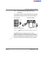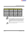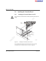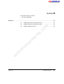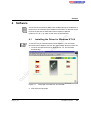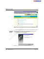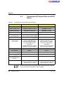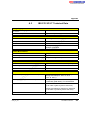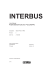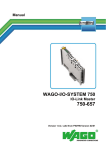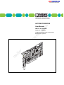
1
AUTOMATIONWORX
m
User Manual
co
IBS PCI SC QS UM E
Order No.: 2698148
on
l
in
ec
om
po
ne
nt
s.
Installing and Starting Up the Controller
Board for PC Systems
s.
nt
ne
po
om
in
ec
on
l
co
m
AUTOMATIONWORX
Revision:
03
Order No.:
2698148
ne
IBS PCI SC QS UM E
in
ec
om
po
Designation:
03/2006
nt
s.
co
m
User Manual
Installing and Starting Up the Controller Board for PC Systems
Order No. 2725260
Order No. 2730187
Order No. 2730080
on
l
This user manual is valid for:
IBS PCI SC/I-T
IBS PCI SC/RI-LK
IBS PCI SC/RI/I-T
6190_en_03
PHOENIX CONTACT
IBS PCI SC QS UM E
Please Observe the Following Notes
In order to ensure the safe use of the product described, we recommend that you
read this manual carefully. The following notes provide information on how to use
this manual.
User Group of This Manual
co
m
The use of products described in this manual is oriented exclusively to qualified
application programmers and software engineers, who are familiar with the safety
concepts of automation technology and applicable national standards.
nt
Explanation of Symbols Used
s.
Phoenix Contact accepts no liability for erroneous handling or damage to products
from Phoenix Contact or third-party products resulting from disregard of information
contained in this manual.
ne
The attention symbol refers to an operating procedure which, if not carefully
followed, could result in damage to hardware and software or personal injury.
om
po
The note symbol informs you of conditions that must strictly be observed to achieve
error-free operation. It also gives you tips and advice on the efficient use of
hardware and on software optimization to save you extra work.
in
ec
The text symbol refers to detailed sources of information (manuals, data sheets,
literature, etc.) on the subject matter, product, etc. This text also provides helpful
information for the orientation in the manual.
We Are Interested in Your Opinion
We are constantly striving to improve the quality of our manuals.
on
l
Should you have any suggestions or recommendations for improvement of the
contents and layout of our manuals, please send us your comments.
PHOENIX CONTACT GmbH & Co. KG
Documentation Services
32823 Blomberg
Germany
Phone
Fax
E-mail
PHOENIX CONTACT
+49 - 52 35 - 30 0
+49 - 52 35 - 34 20 21
[email protected]
6190_en_03
IBS PCI SC QS UM E
General Terms and Conditions of Use for Technical Documentation
Phoenix Contact GmbH & Co. KG reserves the right to alter, correct, and/or
improve the technical documentation and the products described in the technical
documentation at its own discretion and without giving any notice.
m
The provision of technical documentation (in particular data sheets, installation
instructions, manuals, etc.) does not constitute any further duty on the part of
Phoenix Contact GmbH & Co. KG to furnish information on alterations to products
and/or technical documentation. Any other agreement shall only apply if expressly
confirmed in writing by Phoenix Contact GmbH & Co. KG. Please note that the
supplied documentation is product-specific documentation only.
ne
nt
s.
co
Although Phoenix Contact GmbH & Co. KG makes every effort to ensure that the
information content is accurate, up-to-date, and state-of-the-art, technical
inaccuracies and/or printing errors in the information cannot be ruled out.
Phoenix Contact GmbH & Co. KG does not offer any guarantees as to the
reliability, accuracy or completeness of the information provided.
Phoenix Contact GmbH & Co. KG accepts no liability or responsibility for errors or
omissions in the content of the technical documentation (in particular data sheets,
installation instructions, manuals, etc.).
on
l
in
ec
om
po
As far as is permissible by applicable jurisdiction, no guarantee or claim for liability
for defects whatsoever shall be granted in conjunction with the information available
in the technical documentation, whether expressly mentioned or implied. This
information does not include any guarantees on quality, does not describe any fair
marketable quality and does not make any claims as to quality guarantees or
guarantees on the suitability for a special purpose.
Phoenix Contact GmbH & Co. KG reserves the right to alter, correct, and/or
improve the information and the products described in the information at its own
discretion and without giving any notice.
6190_en_03
PHOENIX CONTACT
IBS PCI SC QS UM E
Statement of Legal Authority
This manual, including all illustrations contained herein, is copyright protected. Use
of this manual by any third party is forbidden. Reproduction, translation, or
electronic and photographic archiving or alteration requires the express written
consent of Phoenix Contact. Violations are liable for damages.
Phoenix Contact reserves the right to make any technical changes that serve the
purpose of technical progress.
co
m
Phoenix Contact reserves all rights in the case of patent award or listing of a
registered design. Third-party products are always named without reference to
patent rights. The existence of such rights shall not be excluded.
Windows 95, Windows 98, Windows NT 4.0, and MS-DOS are trademarks of the
Microsoft Corporation.
s.
All other product names used are trademarks of the respective organizations.
nt
Internet
ne
Up-to-date information on Phoenix Contact products can be found on the Internet
at:
www.phoenixcontact.com
po
Make sure you always use the latest documentation.
It can be downloaded at:
om
www.download.phoenixcontact.com
A conversion table is available on the Internet at:
on
l
in
ec
www.download.phoenixcontact.com/general/7000_en_00.pdf
PHOENIX CONTACT
6190_en_03
Table of Contents
1 Preface .............................................................................................................1-3
Application.................................................................................. 1-3
1.2
Contents..................................................................................... 1-3
1.3
Hardware and Software Requirements ...................................... 1-3
1.4
Additional Documentation .......................................................... 1-4
co
m
1.1
2.3
Structure of the Controller Board ............................................... 2-4
2.2.1
Display Elements of the Controller Board .....................2-5
2.2.2
Serial RS-232 Interface (Mini-DIN Female Connector) .2-7
Setting Up the Controller Board ................................................. 2-8
DIP Switches for Setting the Board Number .................2-8
om
2.3.1
Installing the Controller Board.................................................. 2-10
2.4.1
Installing the Controller Board in the PC .....................2-10
2.4.2
Bus System Connection ..............................................2-12
in
ec
2.4
ESD Regulations ...........................................................2-3
ne
2.2
nt
Unpacking the Controller Board ................................................. 2-3
2.1.1
po
2.1
s.
2 IBS PCI SC/I-T Hardware Installation...............................................................2-3
3 IBS PCI SC/RI-LK and IBS PCI SC/RI/I-T Hardware Installation .....................3-3
on
l
3.1
3.1.1
3.2
3.3
6190_en_03
Unpacking the System Coupler.................................................. 3-4
ESD Regulations ...........................................................3-4
Structure of the System Coupler ................................................ 3-5
3.2.1
System Coupler Indicators ............................................3-6
3.2.2
Serial RS-232 Interface (Mini-DIN Female Connector)3-11
Setting Up the System Coupler................................................ 3-12
3.3.1
DIP Switches for Setting the Board Number ...............3-12
3.3.2
DIP Switch for Selecting the Baud Rate .....................3-14
3.3.3
DIP Switches for
Setting Up the Slave Expansion Module .....................3-15
PHOENIX CONTACT
i
IBS PCI SC QS UM E
3.4
Installing the System Coupler .................................................. 3-19
3.4.1
External Voltage Supply ..............................................3-19
3.4.2
Installing the System Coupler in the PC .....................3-20
3.4.3
Bus System Connection ..............................................3-22
4 Software............................................................................................................4-3
Installing the Driver for Windows NT 4.0.................................... 4-3
4.2
Installing the Driver for Windows 2000....................................... 4-6
4.3
Installing Additional Tools .......................................................... 4-8
co
m
4.1
Default Upon Delivery ...................................................5-3
5.1.2
Starting Up Without Parameterization of the Master .....5-5
5.1.3
Starting Up With Parameterization of the Master ..........5-6
5.1.4
Changing the Configuration Using Firmware Services .5-7
ii
om
Changing the Configuration Using
IBS CMD SWT G4 E ...................................................5-13
System Behavior and Diagnostics ........................................... 5-14
Reset Behavior ...........................................................5-14
5.2.2
Message Behavior ......................................................5-15
5.2.3
Data Behavior .............................................................5-16
in
ec
5.2.1
Technical Appendix....................................................................................... A-1
on
l
A
ne
5.1.1
5.1.5
5.2
nt
Start Behavior ............................................................................ 5-3
po
5.1
s.
5 Behavior of the IBS PCI SC/RI-LK and IBS PCI SC/RI/I-T System Couplers ..5-3
PHOENIX CONTACT
A1
Basic Functions of the Driver (Device Driver Interface, DDI) .... A-1
A2
Comparison of Polymer Fibers and HCS Fibers ....................... A-2
A3
IBS PCI SC/I-T Technical Data ................................................. A-3
A4
IBS PCI SC/RI-LK Technical Data ............................................ A-5
A5
IBS PCI SC/RI/I-T Technical Data ............................................ A-7
A6
Ordering Data............................................................................ A-9
6190_en_03
Section 1
This section informs you about
– the contents of this manual.
Preface .................................................................................................................1-3
Application...................................................................................1-3
1.2
Contents......................................................................................1-3
1.3
Hardware and Software Requirements .......................................1-3
1.4
Additional Documentation ...........................................................1-4
on
l
in
ec
om
po
ne
nt
s.
co
m
1.1
6190_en_03
PHOENIX CONTACT
1-1
m
co
s.
nt
ne
po
om
in
ec
on
l
1-2
PHOENIX CONTACT
6190_en_03
Preface
1
Preface
1.1
Application
s.
Contents
nt
1.2
co
m
This user manual helps you to start up and operate a controller board or a
system coupler for PCs with PCI bus. It is assumed the user has knowledge
and experience in the operation of PCs and the Windows NT 4.0 operating
system.
ne
This manual describes the easy startup of an INTERBUS system as
follows:
1. Hardware installation
Controller board
IBS PCI SC/I-T
Order No. 27 25 26 0
System coupler
IBS PCI SC/RI-LK
IBS PCI SC/RI/I-T
Order No. 27 30 18 7
Order No. 27 30 08 0
in
ec
–
on
l
–
6190_en_03
–
Hardware and Software Requirements
om
1.3
po
2. Driver software installation
Minimum PC requirements:
Pentium processor with 200 MHz
32 MB main memory (RAM)
30 MB free hard disk space
One free PCI slot, according to specification 2.1 or later
(two free slots for system coupler)
Microsoft Windows NT 4.0
PHOENIX CONTACT
1-3
IBS PCI SC QS UM E
1.4
Additional Documentation
Driver and documentation CD for the controller board
CD IBS PCI SC
Order No. 27 33 00 3
on
l
in
ec
om
po
ne
nt
s.
co
m
"Configuring and Installing INTERBUS" User Manual
IBS SYS PRO INST UM E
Order No. 27 43 80 2
1-4
PHOENIX CONTACT
6190_en_03
Section 2
This section informs you about
– the hardware installation of the IBS PCI SC/I I-T controller board.
IBS PCI SC/I-T Hardware Installation...................................................................2-3
Unpacking the Controller Board ..................................................2-3
2.1.1
Serial RS-232 Interface (Mini-DIN Female Connector)..2-7
Setting Up the Controller Board ..................................................2-8
2.3.1
DIP Switches for Setting the Board Number..................2-8
Installing the Controller Board...................................................2-10
2.4.1
Installing the Controller Board in the PC......................2-10
2.4.2
Bus System Connection...............................................2-12
on
l
in
ec
om
po
2.4
m
2.2.2
co
Display Elements of the Controller Board ......................2-5
s.
2.3
Structure of the Controller Board ................................................2-4
2.2.1
nt
2.2
ESD Regulations............................................................2-3
ne
2.1
6190_en_03
PHOENIX CONTACT
2-1
m
co
s.
nt
ne
po
om
in
ec
on
l
2-2
PHOENIX CONTACT
6190_en_03
IBS PCI SC/I-T Hardware Installation
2
IBS PCI SC/I-T Hardware Installation
2.1
Unpacking the Controller Board
The controller board is supplied in an ESD bag.
ESD Regulations
s.
2.1.1
co
m
To avoid possible damage to the board and the PC, unpack and pack the
board, and insert it in the PC in accordance with ESD regulations.
nt
Observe the necessary safety measures when handling components that
may be damaged by electrostatic discharge.
on
l
in
ec
om
po
ne
Persons who handle the controller board must protect it by observing the
ESD instructions before packing or unpacking the board, opening control
boxes or control cabinets, and before touching the board.
6190_en_03
PHOENIX CONTACT
2-3
IBS PCI SC QS UM E
2.2
Structure of the Controller Board
nt
s.
co
m
5
ne
4
po
3
in
ec
1
om
2
on
l
Figure 2-1
2-4
PHOENIX CONTACT
6 1 9 0 A 0 0 2
Structure of the IBS PCI SC/I-T controller board
The controller board has the following components:
1
INTERBUS remote bus interface
2
Connection for direct inputs and outputs
(is not supported at present)
3
RS-232 interface
4
Diagnostic LEDs (indicators)
5
DIP switches for setting the board number
6190_en_03
IBS PCI SC/I-T Hardware Installation
2.2.1
Display Elements of the Controller Board
F C
S C
H F
F A IL
P F
B S A
R S 2 3 2
on
l
in
ec
om
po
ne
nt
s.
co
m
The basic functions are checked when the controller board is switched on.
If there are no errors, the green SC LED flashes after approximately 5
seconds. If the HF LED goes out, the driver for the controller board is
active. The status of the INTERBUS bus system is indicated by other
LEDs.
6 1 9 0 A 0 0 4
Figure 2-2
IBS PCI SC/I-T indicators
The meaning and the color of the indicators are shown in Table 2-1:
6190_en_03
PHOENIX CONTACT
2-5
IBS PCI SC QS UM E
Table 2-1
IBS PCI SC/I-T indicators
Color
Meaning
FC
Green
Reserved
SC
Green
INTERBUS ready/running
Flashing:
The controller board is in READY or ACTIVE state
ON:
The controller board and the connected INTERBUS are in the RUN state
Yellow
Host failure
ON:
Host system failure; driver not yet started
Red
Failure
ON
Error has occurred in the INTERBUS system
Yellow
Peripheral failure
ON:
Peripheral failure of an INTERBUS device
Yellow
Bus segment aborted
ON:
One or more bus segments are disconnected
co
s.
on
l
in
ec
om
BSA
nt
PF
ne
FAIL
po
HF
m
Des.
2-6
PHOENIX CONTACT
6190_en_03
IBS PCI SC/I-T Hardware Installation
2.2.2
Serial RS-232 Interface (Mini-DIN Female
Connector)
The serial RS-232 interface is a 6-pos. Mini-DIN female connector (PS/2)
on the slot plate. The board is connected to the PC with the RS-232 cable
PRG CAB MINI-DIN (Order No. 27 30 61 1) as shown in the following.
F ro n t p a n e l
6
8
m
co
5
D
2
8
D
S
1
2
2
3
5
5
s.
5
F e m a le s id e
D
1
6
3
S
nt
2
T X
R X
G N
R T
C T
ne
1
R S - 2 3 2 c a b le
6 1 9 0 B 0 1 4
Diagnostic interface and RS-232 cable for connection to a
PC
om
Figure 2-3
po
6 - p o s . M in i- D IN
fe m a le c o n n e c to r ( P S /2 )
on
l
in
ec
With the IBS CMD SWT G4 E software, the user can configure,
parameterize, and diagnose the INTERBUS system. Parameterization and
configuration information can be stored permanently on the controller
board using IBS CMD SWT G4 E. In addition, the firmware of the controller
board can be downloaded via the serial interface (RS-232). In this way, it
is possible to meet future system requirements by means of updates.
6190_en_03
PHOENIX CONTACT
2-7
IBS PCI SC QS UM E
2.3
Setting Up the Controller Board
2.3.1
DIP Switches for Setting the Board Number
co
m
If several INTERBUS PCI boards are used in a PC, each board must be
given a number. The numbers differentiate the boards in the system. DIP
switches 1 ... 3 for setting the board number are on the upper edge of the
board. The board number can be set anywhere between 1 and 8. The
default value (upon delivery) is 1. If only one INTERBUS PCI board is used,
the board number does not need to be changed.
on
l
in
ec
om
po
ne
nt
s.
Make a note of the board number because this number must be entered
when installing the driver.
6 1 9 0 A 0 0 3
Figure 2-4
2-8
PHOENIX CONTACT
Default settings of the DIP switches (board number 1)
6190_en_03
IBS PCI SC/I-T Hardware Installation
DIP switches for setting the board number
DIP Switch 1
DIP Switch 2
DIP Switch 3
1
OFF
OFF
OFF
2
ON
OFF
OFF
3
OFF
ON
OFF
4
ON
ON
5
OFF
OFF
6
ON
OFF
7
OFF
ON
8
ON
co
OFF
s.
ON
ON
ON
ON
ne
ON
Default
m
Board Number
nt
Table 2-2
po
DIP switches 4 ... 7 are reserved for extensions, and must not be changed.
in
ec
om
DIP switch 8 (test mode) is not used for setting board numbers. It is used
to activate test mode. When the controller board is restarted with activated
test mode, it starts the INTERBUS system with physical addressing, and
initializes it. During test mode the controller board does not respond to
instructions of the host system (PC). The controller board initializes the
INTERBUS system, and then operates it independently. Outputs are not
set.
on
l
Test mode is not intended for normal operation of the controller board. Set
switch 8 to OFF to deactivate test mode.
6190_en_03
PHOENIX CONTACT
2-9
IBS PCI SC QS UM E
2.4
Installing the Controller Board
2.4.1
Installing the Controller Board in the PC
co
m
Switch off the PC and disconnect the mains plug before opening the PC
casing.
on
l
in
ec
om
po
ne
nt
s.
a
6 1 9 0 A 0 0 5
Figure 2-5
Installing the controller board in the PC
The controller board needs one PCI bus slot in the PC. The power
consumption of the controller board is 3.5 W at 5 V (typical).
2-10
PHOENIX CONTACT
6190_en_03
IBS PCI SC/I-T Hardware Installation
1. Ensure that you are grounded before installing the board in the PC
casing.
2. Power down and disconnect the mains plug.
3. Open the PC.
4. Insert the controller board in the PCI bus slot, make sure that the
system connector is well-contacted and the board is securely placed.
5. Secure the module using the mounting screw (a) (see Figure 2-5).
co
m
To ensure error-free operation, the mounting plate of the module must be
fastened to the PC casing. The PC casing must be grounded in compliance
with the regulations.
6. Close the PC.
s.
7. Plug in the PC and switch it on again.
on
l
in
ec
om
po
ne
nt
Now the controller board is completely installed in your PC.
6190_en_03
PHOENIX CONTACT
2-11
IBS PCI SC QS UM E
2.4.2
Bus System Connection
ne
nt
s.
co
m
Connect the outgoing INTERBUS remote bus cable to the "REMOTE OUT"
connection of the controller board (see Figure 2-6).
in
ec
om
po
R e m o te
O U T
Connecting the INTERBUS remote bus cable
on
l
Figure 2-6
6 1 9 0 A 0 0 6
2-12
PHOENIX CONTACT
6190_en_03
Section 3
This section informs you about
– the hardware installation of the IBS PCI SC/RI-LK and
IBS PCI SC/RI/I-T system couplers.
IBS PCI SC/RI-LK and IBS PCI SC/RI/I-T Hardware Installation .........................3-3
Unpacking the System Coupler...................................................3-4
3.4
3.2.2
Serial RS-232 Interface (Mini-DIN Female Connector)3-11
co
System Coupler Indicators.............................................3-6
s.
Setting Up the System Coupler.................................................3-12
3.3.1
DIP Switches for Setting the Board Number................3-12
3.3.2
DIP Switch for Selecting the Baud Rate ......................3-14
3.3.3
DIP Switches for Setting Up
the Slave Expansion Module .......................................3-15
nt
3.3
Structure of the System Coupler .................................................3-5
3.2.1
ne
3.2
ESD Regulations............................................................3-4
m
3.1.1
Installing the System Coupler ...................................................3-19
3.4.1
3.4.2
External Voltage Supply...............................................3-19
Installing the System Coupler in the PC ......................3-20
Bus System Connection...............................................3-22
on
l
in
ec
om
3.4.3
po
3.1
6190_en_03
PHOENIX CONTACT
3-1
m
co
s.
nt
ne
po
om
in
ec
on
l
3-2
PHOENIX CONTACT
6190_en_03
IBS PCI SC/RI-LK and IBS PCI SC/RI/I-T Hardware Installation
3
IBS PCI SC/RI-LK and IBS PCI SC/RI/I-T
Hardware Installation
on
l
in
ec
om
po
ne
nt
s.
co
m
Because the IBS PCI SC/RI-LK and IBS PCI SC/RI/I-T system couplers
basically have the same structure and only differ in their INTERBUS
connections, the following section only describes the system coupler with
an optical fiber connection (Order designation IBS PCI SC/RI-LK).
6 3 8 3 A 0 0 1
Figure 3-1
6190_en_03
IBS PCI SC/RI/I-T system coupler
PHOENIX CONTACT
3-3
IBS PCI SC QS UM E
3.1
Unpacking the System Coupler
The system coupler is supplied in an ESD bag.
ESD Regulations
co
3.1.1
m
To avoid possible damage to the system coupler and the PC, unpack and
pack the system coupler, and insert it in the PC in accordance with ESD
regulations.
s.
Observe the necessary safety measures when handling components that
may be damaged by electrostatic discharge.
on
l
in
ec
om
po
ne
nt
Persons who handle the system coupler must protect it by observing the
ESD instructions before packing or unpacking the system coupler, opening
control boxes or control cabinets, and before touching the system coupler.
3-4
PHOENIX CONTACT
6190_en_03
IBS PCI SC/RI-LK and IBS PCI SC/RI/I-T Hardware Installation
3.2
Structure of the System Coupler
m
8
co
7
nt
s.
6
ne
5
om
po
4
in
ec
3
on
l
Figure 3-2
6190_en_03
2
1
6 1 9 0 B 0 0 9
Structure of the IBS PCI SC/RI-LK system coupler
The system coupler has the following components:
1
RS-232 interface
2
Master interface (Remote OUT, outgoing remote bus)
3
Connection of the external 24 V supply voltage for the slave part
4
Slave interface (Remote OUT, outgoing remote bus)
5
Slave interface (Remote IN, incoming remote bus)
6
Diagnostic LEDs (indicators)
7
DIP switches for the slave configuration
8
DIP switches for the master configuration
PHOENIX CONTACT
3-5
IBS PCI SC QS UM E
3.2.1
System Coupler Indicators
Master Board
IBS PCI SC/RI-LK master board indicators
co
Table 3-1
m
When the system coupler is switched on, the processor and the firmware
of the master board are checked for the required basic functions. If there
are no errors, the green SC LED flashes after approximately 5 seconds. If
the HF LED goes out, the driver for the system coupler is active. The
meaning and the color of the indicators are shown in the following table:
Color
Meaning
FC
Green
Reserved
SC
Green
INTERBUS ready/running
Flashing:
The controller board is in READY or ACTIVE state
ON:
The controller board and the connected INTERBUS are in the RUN state
Yellow
Host failure
ON:
Host system failure; driver not yet started
Red
Failure
ON
Error has occurred in the INTERBUS system
Yellow
Peripheral failure
PF
nt
ne
po
ON:
Peripheral failure of an INTERBUS device
Yellow
Bus segment aborted
ON:
One or more bus segments are disconnected
on
l
BSA
om
FAIL
in
ec
HF
s.
Des.
3-6
PHOENIX CONTACT
6190_en_03
in
ec
ne
B S A F A IL S C
R S 2 3 2
om
P F
H F
po
F C
nt
s.
co
m
IBS PCI SC/RI-LK and IBS PCI SC/RI/I-T Hardware Installation
Master board LED indicators
on
l
Figure 3-3
6 2 0 5 A 0 0 4
6190_en_03
PHOENIX CONTACT
3-7
IBS PCI SC QS UM E
The system coupler with an optical fiber interface (IBS PCI SC/RI-LK) also
has an LED to diagnose the outgoing optical fiber interface:
Table 3-2
LED to diagnose the outgoing optical fiber interface
Color
Meaning
FO3
Yellow
Fiber optic 3
ON:
The FO3 LED is on if the initialization of the outgoing interface is not OK
or if a MAU warning occurs due to poor transmission quality on the path
(this applies to the data forward path/transmitter for the following
module, the state of the data return path/receiver is diagnosed from the
following module).
on
l
F 0 3
in
ec
R E M O T E
om
po
ne
nt
s.
co
m
Des.
6 2 0 5 A 0 1 1
Figure 3-4
3-8
PHOENIX CONTACT
LED to diagnose the outgoing optical fiber interface
6190_en_03
IBS PCI SC/RI-LK and IBS PCI SC/RI/I-T Hardware Installation
Slave Expansion Module
on
l
6190_en_03
Figure 3-5
R C
R D
F 0 2
U L
B A
F 0 1
E IN
in
ec
om
po
ne
nt
s.
co
m
The LED indicators on the slave expansion module provide information on
the state of the higher-level INTERBUS system and the slave expansion
module.
6 2 0 5 A 0 0 9
Slave expansion module LED indicators
PHOENIX CONTACT
3-9
IBS PCI SC QS UM E
The meanings of the LEDs can be found in the following table:
Table 3-3
IBS PCI SC/RI-LK slave module indicators
Color
Meaning
UL
Green
U (Logic)
ON:
Operating voltage present
Green
Remote bus check
ON:
The higher-level controller board is connected
Green
Bus active
Flashing:
Bus is in the ACTIVE state
ON:
Bus is in the RUN state
Red
Remote bus disabled
ON:
The outgoing remote bus interface is disconnected
Yellow
Fiber optic 1
ON:
The FO1 LED is on if the initialization of the incoming interface is not OK
or if an MAU warning occurs due to poor transmission quality on the path
(this applies to the data return path/transmitter for the previous module,
the state of the data forward path/receiver is diagnosed from the
previous module).
Yellow
Fiber optic 2
ON:
The FO2 LED is on if the initialization of the outgoing interface is not OK
or if an MAU warning occurs due to poor transmission quality on the path
(this applies to the data forward path/transmitter for the following
module, the state of the data return path/receiver is diagnosed from the
following module).
on
l
FO2
3-10
co
s.
nt
ne
FO1
po
RD
om
BA
in
ec
RC
m
Des.
PHOENIX CONTACT
The FO1 and FO2 LEDs are not available on the system coupler with
D-SUB interface (IBS PCI SC/RI/I-T).
6190_en_03
IBS PCI SC/RI-LK and IBS PCI SC/RI/I-T Hardware Installation
3.2.2
Serial RS-232 Interface (Mini-DIN Female
Connector)
The serial RS-232 interface is a 6-pos. Mini-DIN female connector (PS/2)
on the slot plate. The board is connected to the PC with the RS-232 cable
PRG CAB MINI-DIN (Order No. 27 30 61 1) as shown in the following.
F ro n t p a n e l
6
8
m
co
5
D
2
8
D
S
1
6
3
S
1
2
2
3
5
5
s.
5
F e m a le s id e
D
nt
2
T X
R X
G N
R T
C T
ne
1
R S - 2 3 2 c a b le
6 1 9 0 B 0 1 4
Diagnostic interface and RS-232 cable for connection to a
PC
om
Figure 3-6
po
6 - p o s . M in i- D IN
fe m a le c o n n e c to r ( P S /2 )
on
l
in
ec
With the IBS CMD SWT G4 E software, the user can configure,
parameterize, and diagnose the INTERBUS system. Parameterization and
configuration information can be stored permanently on the controller
board using IBS CMD SWT G4 E. In addition, the firmware of the controller
board can be downloaded via the serial interface (RS-232). In this way, it
is possible to meet future system requirements by means of updates.
6190_en_03
PHOENIX CONTACT
3-11
IBS PCI SC QS UM E
3.3
Setting Up the System Coupler
3.3.1
DIP Switches for Setting the Board Number
on
l
in
ec
om
po
ne
nt
s.
co
m
If several INTERBUS PCI boards are used in a PC, each board must be
given a number. The numbers differentiate the boards in the system. DIP
switches 1 ... 3 for setting the board number are on the upper edge of the
board. The board number can be set anywhere between 1 and 8 (binary
encoded). The default value (upon delivery) is 1. If only one INTERBUS
PCI board is used, the board number does not need to be changed.
6 2 0 5 A 0 0 5
Figure 3-7
3-12
PHOENIX CONTACT
Default settings of the DIP switches (board number 1)
6190_en_03
IBS PCI SC/RI-LK and IBS PCI SC/RI/I-T Hardware Installation
DIP switches for setting the board number
DIP Switch 1
DIP Switch 2
DIP Switch 3
1
OFF
OFF
OFF
2
ON
OFF
OFF
3
OFF
ON
OFF
4
ON
ON
5
OFF
OFF
6
ON
OFF
7
OFF
ON
8
ON
co
OFF
s.
ON
ON
ON
ON
ne
ON
Default
m
Board Number
nt
Table 3-4
on
l
in
ec
om
po
DIP switches 4, 5, 6, and 8 are reserved for extensions, and must not be
changed.
6190_en_03
PHOENIX CONTACT
3-13
IBS PCI SC QS UM E
3.3.2
DIP Switch for Selecting the Baud Rate
in
ec
om
po
ne
nt
s.
co
m
The baud rate of the lower-level INTERBUS system can be set using DIP
switch 7 of the master board. The default upon delivery (switch position
"OFF") is 500 kbaud. Alternatively, 2 Mbaud (switch position "ON") can be
set.
6 2 0 5 A 0 0 5
on
l
Figure 3-8
3-14
PHOENIX CONTACT
DIP switch for selecting the baud rate
With the IBS PCI SC/RI/I-T system coupler, the baud rate is selected
automatically. Therefore DIP switch 7 does not have to be set.
6190_en_03
IBS PCI SC/RI-LK and IBS PCI SC/RI/I-T Hardware Installation
3.3.3
DIP Switches for Setting Up the Slave Expansion
Module
in
ec
om
po
ne
nt
s.
co
m
The DIP switches are located at the top left of the slave expansion module.
These DIP switches are used to configure the slave part of the system
coupler.
on
l
Figure 3-9
6190_en_03
6 2 0 5 A 0 1 0
DIP switches on the slave expansion module
The DIP switch settings are overwritten by the host PC by means of
software configuration if DIP switch 10 is in the "OFF" position. For further
information on the system coupler configuration, please refer to Section 5
„Behavior of the IBS PCI SC/RI-LK and IBS PCI SC/RI/I-T System
Couplers“.
PHOENIX CONTACT
3-15
IBS PCI SC QS UM E
DIP Switches 1 and 2: Setting the Parameter Channel (PCP)
The width of the parameter channel is set using DIP switches 1 and 2. This
setting also determines the ID code of the remote interface.
The maximum combined width of the parameter channel and the process
data channel is 16 words.
Setting the parameter channel (PCP)
m
Table 3-5
DIP Switch 2
Parameter Channel (PCP)
ID Code
OFF
OFF
0 words
3dec
ON
OFF
1 word
OFF
ON
ON
ON
co
DIP Switch 1
s.
235dec
232dec
4 words
233dec
nt
2 words
ne
DIP Switches 3 ... 6: Setting the Process Data Length
po
The length of the process data is set using DIP switches 3 ... 6.
Table 3-6
om
These DIP switches are also used to specify the length code.
Setting the process data length
Process Data
Length Code
4
5
6
OFF
OFF
OFF
OFF
0 words
00hex/0dec
ON
in
ec
DIP Switches
OFF
OFF
OFF
1 word
01hex/1dec
OFF
ON
OFF
OFF
2 words
02hex/2dec
ON
ON
OFF
OFF
3 words
03hex/3dec
OFF
OFF
ON
OFF
4 words
04hex/4dec
ON
OFF
ON
OFF
5 words
05hex/5dec
OFF
ON
ON
OFF
6 words
06hex/6dec
ON
ON
ON
OFF
7 words
07hex/7dec
OFF
OFF
OFF
ON
8 words
08hex/8dec
on
l
3
3-16
PHOENIX CONTACT
6190_en_03
IBS PCI SC/RI-LK and IBS PCI SC/RI/I-T Hardware Installation
Table 3-6
Setting the process data length
DIP Switches
Process Data
Length Code
4
5
6
ON
OFF
OFF
ON
9 words
09hex/9dec
OFF
ON
OFF
ON
10 words
0Ahex/10dec
ON
ON
OFF
ON
11 words
0Bhex/11dec
OFF
OFF
ON
ON
12 words
ON
OFF
ON
ON
13 words
OFF
ON
ON
ON
14 words
ON
ON
ON
ON
16 words
m
3
s.
co
0Chex/12dec
0Dhex/13dec
0Ehex/14dec
ne
nt
10hex/16dec
0 words
om
Parameter
Channel
Width of the parameter channel and the process data length
Process Data Length (in Words)
0
1
2
3
in
ec
Table 3-7
po
By setting the width of the parameter channel and the process data length,
you can adapt the module to meet your requirements. The following
combinations are available:
4
5
6
7
8
9
10
✔
✔
✔
✔
✔
✔
✔
✔
✔
✔
✔
11
12
✔
✔
✔
✔
✔
✔
✔
✔
✔
✔
2 words
✔
✔
✔
✔
✔
✔
✔
✔
✔
✔
✔
4 words
✔
✔
✔
✔
✔
✔
✔
✔
✔
✔
on
l
1 word
6190_en_03
13
✔
14
16
✔
✔
✔
✔
If you change the configuration of the slave expansion module using DIP
switches, the new configuration is only accepted once the slave expansion
module, the master part, and the host system have been powered up
simultaneously.
PHOENIX CONTACT
3-17
IBS PCI SC QS UM E
DIP Switch 7: Reset Behavior on a Host PC Reset
DIP switch 7 can be used to specify whether a lower-level master system
reset triggers an I/O error in the higher-level system. In the "OFF" position
(default upon delivery) a message is generated so that the higher-level
system can respond. If the switch is in the "ON" position no message is
sent to the higher-level system.
m
DIP Switch 8: Reserved
DIP Switch 9: Setting the Baud Rate
co
DIP switch 8 is reserved. Do not change the switch position.
nt
s.
DIP switch 9 sets the baud rate of the system coupler slave part. In the
"OFF" position the baud rate is 500 kbaud (default value), and in the "ON"
position the baud rate is 2 Mbaud.
ne
DIP Switch 10: Configuration
om
po
DIP switch 10 is of particular significance. If the switch is in the "ON"
position, the system coupler slave part is configured according to the
switch positions of DIP switches 1 to 9. If the switch is in the "OFF" position,
switch positions 1 ... 9 are ignored, and the slave part is parameterized
using a stored configuration or a configuration received from the lowerlevel master.
on
l
in
ec
Therefore only set DIP switch 10 to the "ON" position when starting up your
INTERBUS system or if, for example, you want to check the cabling. For
normal operation it is recommended that DIP switch 10 is in the "OFF"
position and configuration is carried out using software.
3-18
PHOENIX CONTACT
6190_en_03
IBS PCI SC/RI-LK and IBS PCI SC/RI/I-T Hardware Installation
3.4
Installing the System Coupler
3.4.1
External Voltage Supply
m
To operate the system coupler, the slave expansion module must also be
supplied with an external 24 V DC supply voltage. The power consumption
of the slave expansion module is 3.5 W (typical).
in
ec
om
po
ne
nt
s.
co
The supply voltage is connected with a 2-pos. MINI-COMBICON
connector.
on
l
2 4 V
+
6 2 0 5 A 0 0 6
Figure 3-10
6190_en_03
Connecting the external voltage supply for the slave
expansion module
PHOENIX CONTACT
3-19
IBS PCI SC QS UM E
3.4.2
Installing the System Coupler in the PC
on
l
in
ec
om
po
ne
nt
s.
co
m
Switch off the PC and disconnect the mains plug before opening the PC
casing.
Figure 3-11
Installing the system coupler in the PC
The system coupler needs two PCI bus slots in the PC. The power
consumption of the system coupler is 6.5 W at 5 V (typical).
If only one PCI slot and another adjacent slot are free, the PCI system
connector can be removed from the slave expansion module and the
module can be mounted in the free slot. Ensure that the module is secure.
3-20
PHOENIX CONTACT
6190_en_03
IBS PCI SC/RI-LK and IBS PCI SC/RI/I-T Hardware Installation
1. Ensure that you are grounded before installing the system coupler in
the PC casing.
2. Power down and disconnect the mains plug.
3. Open the PC.
4. Insert the system coupler in the slots. Ensure that the system
connector is well-contacted and the system coupler is securely placed.
m
5. Secure the system coupler using the mounting screws (see
Figure 3-11).
co
To ensure error-free operation, the mounting plate of the system coupler
must be fastened to the PC casing. The PC casing must be grounded in
compliance with the regulations.
s.
6. Close the PC.
7. Plug in the PC and switch it on again.
on
l
in
ec
om
po
ne
nt
Now the system coupler is completely installed in your PC.
6190_en_03
PHOENIX CONTACT
3-21
IBS PCI SC QS UM E
3.4.3
Bus System Connection
The optical fiber cable for the remote bus must be fitted with appropriate FSMA connectors. HCS fiber cables and polymer fiber cables can be used
as optical fiber cables (see table "Comparison of polymer fibers and HCS
fibers" on page A-2).
R e m o te
IN
in
ec
om
po
ne
nt
s.
co
m
Plug the connectors into the sockets provided and secure the connections
with the cap nuts. "Remote IN" indicates the connection for the incoming
remote bus, while "Remote OUT" indicates the connection for the outgoing
remote bus of the slave interface. On the lower-level master "Remote OUT"
indicates the master interface.
S la v e
on
l
R e m o te
O U T
M a s te r
R e m o te
O U T
6 2 0 5 A 0 0 3
Figure 3-12
3-22
PHOENIX CONTACT
Connecting the bus system via optical fibers
6190_en_03
Section 4
This section informs you about
– the driver installation.
Software................................................................................................................4-3
Installing the Driver for Windows NT 4.0.....................................4-3
4.2
Installing the Driver for Windows 2000........................................4-6
4.3
Installing Additional Tools ...........................................................4-8
on
l
in
ec
om
po
ne
nt
s.
co
m
4.1
6190_en_03
PHOENIX CONTACT
4-1
m
co
s.
nt
ne
po
om
in
ec
on
l
4-2
PHOENIX CONTACT
6190_en_03
Software
4
Software
Installing the Driver for Windows NT 4.0
co
4.1
m
The Device Driver Interface (DDI) is also installed during the installation of
the driver for the controller board. Additional information on the DDI can be
found in the IBS PC SC SWD UM E Driver Reference Manual
(Order No. 27 45 17 2), which is part of the System Manual.
s.
To use this CD you need Microsoft Internet Explorer. You can install
Microsoft Internet Explorer 5.5 from the "[drive:\IE55]" directory of the CD.
on
l
in
ec
om
po
ne
nt
1. Insert the CD with the driver for Windows NT 4.0. The CD starts
automatically.
Figure 4-1
Start page of the IBS PCI SC CD-ROM
2. Now select the language.
6190_en_03
PHOENIX CONTACT
4-3
Tools and driver on the IBS PCI SC CD-ROM
po
Figure 4-2
ne
nt
s.
co
m
IBS PCI SC QS UM E
om
3. Click on "Driver for Windows NT 4.0" in the "Tools and Driver" section.
To install the driver and other tools, select "Run this program from its
current location" in the "File Download" dialog box.
on
l
in
ec
4. Driver installation is now completed.
Figure 4-3
4-4
PHOENIX CONTACT
Driver setup for the IBS PCI MPM driver
6190_en_03
Software
5. Now follow the instructions on the screen.
During driver installation, enter the board number set using the DIP
switches. Information on this can be found in "DIP Switches for Setting the
Board Number" on page 2-8 and page 3-12.
6. Restart the computer.
on
l
in
ec
om
po
ne
nt
s.
co
m
If you want to change the driver settings, restart the driver setup.
6190_en_03
PHOENIX CONTACT
4-5
IBS PCI SC QS UM E
4.2
Installing the Driver for Windows 2000
Install the driver for Windows 2000 using the hardware assistant. If a new
hardware was installed on the PC, the hardware assistant is activated
automatically when Windows 2000 is started.
on
l
in
ec
om
po
ne
nt
s.
co
m
If the hardware assistant is not activated automatically after having
installed a PCI controller board or a PCI system coupler you can start the
hardware assistant from the Windows 2000 system control.
4-6
PHOENIX CONTACT
Figure 4-4
Windows 2000 control panel
6190_en_03
Windows 2000 hardware assistant
nt
Figure 4-5
s.
co
m
Software
ne
When installing the driver, enter the board number set via DIP switch.
For further information see section "DIP Switches for Setting the Board
Number" on page 2-8 and page 3-12.
on
l
in
ec
om
po
The include and header files from the "[Drive:\install\driver\win2000\ddi]"
directory must be copied manually into the appropriate directory because
the driver for Windows 2000 will be installed with the help of the
hardware assistant.
6190_en_03
PHOENIX CONTACT
4-7
IBS PCI SC QS UM E
4.3
Installing Additional Tools
After installing the driver it is possible to:
Install the High-Level Language Interface HLI to create individual
applications in a high-level language or use one of the example
programs.
–
Install IBS CMD SWT G4 E software to configure, monitor, and
diagnose your INTERBUS system or install the INTERBUS OPC
server.
co
m
–
s.
The High-Level Language Interface HLI and the example programs can be
found on the supplied CD in the "[Drive:\Driver]" directory. The HLI and
example programs are installed in the same way as the driver.
ne
nt
IBS CMD SWT G4 E software (Order No. 27 21 44 2) and the INTERBUS
OPC server IBS OPC SERVER (Order No. 27 29 12 7) can be ordered
from Phoenix Contact.
on
l
in
ec
om
po
Complete documentation for the controller boards is also available in pdf
format on the IBS PCI SC CD-ROM, in the "Documentation" section.
Figure 4-6
4-8
PHOENIX CONTACT
Documentation on the IBS PCI SC CD-ROM
6190_en_03
Section 5
This section informs you about
– the system coupler configuration paths.
Behavior of the IBS PCI SC/RI-LK and IBS PCI SC/RI/I-T System Couplers ......5-3
Default Upon Delivery ....................................................5-3
5.1.2
Starting Up Without Parameterization of the Master......5-5
m
5.1.1
Starting Up With Parameterization of the Master...........5-6
5.1.4
Changing the Configuration Using Firmware Services ..5-7
5.1.5
Changing the Configuration
Using IBS CMD SWT G4 E..........................................5-13
s.
co
5.1.3
System Behavior and Diagnostics ............................................5-14
Reset Behavior ............................................................5-14
5.2.2
Message Behavior .......................................................5-15
5.2.3
Data Behavior ..............................................................5-16
nt
5.2.1
on
l
in
ec
om
po
5.2
Start Behavior .............................................................................5-3
ne
5.1
6190_en_03
PHOENIX CONTACT
5-1
m
co
s.
nt
ne
po
om
in
ec
on
l
5-2
PHOENIX CONTACT
6190_en_03
Behavior of the IBS PCI SC/RI-LK and IBS PCI SC/RI/I-T System Couplers
5
Behavior of the IBS PCI SC/RI-LK and
IBS PCI SC/RI/I-T System Couplers
Start Behavior
m
5.1
co
The start behavior and the configuration of the system couplers is affected
by:
The DIP switches for setting up the slave expansion module (see
section 3.3.3 on page 3-15).
–
A configuration for the slave expansion module stored in the slave
memory, which is loaded when the slave is powered up.
–
A configuration for the system coupler stored in the master memory,
which is loaded when the host system is powered up.
–
Firmware services, which are sent to the system coupler by the host or
higher-level INTERBUS system.
Default Upon Delivery
om
5.1.1
po
ne
nt
s.
–
To ensure that the system couplers can be operated in the INTERBUS
system, they must be parameterized to meet your requirements.
on
l
in
ec
By default, the configuration is deactivated using the DIP switches on the
slave expansion module and the slave part is configured using a
configuration stored in the slave expansion module memory. The default
upon delivery is ID code 03dec and 16 process data words in the higherlevel INTERBUS system. The data transmission rate is 500 kbaud and the
I/O error message is active if the power for the master board fails.
6190_en_03
The following diagram shows the basic sequence when starting the system
couplers:
PHOENIX CONTACT
5-3
5-4
PHOENIX CONTACT
Figure 5-1
N o
ne
po
om
P a r a m e te r iz a tio n
is c a r r ie d o u t
fro m m e m o ry
Y e s
S la v e s ta r tu p
S y s te m c o u p le r is
re a d y -to -o p e ra te ; c o m m .
to th e m a s te r a n d h o s t
P a r a m e te r iz a tio n
is c a r r ie d o u t
a n d s a v e d
co
m
M a s te r s ta rtu p
s.
M a s te r is n o t
p a r a m e te r iz e d ; c o m m .
to th e h o s t
M a s te r re a d s
c o n fig u r a tio n o f
th e s la v e
N o
M a s te r is r e a d y -to -o p e r a te ;
c o m m u n ic a tio n
to th e h o s t
L o w e r - le v e l
m a s te r s e n d s
p a r a m e te r iz a tio n
M a s te r /s la v e o r
s la v e o n ly
s ta rtu p
C o n fig u r a tio n
r e c e iv e d
nt
P a r a m e te r iz a tio n
in th e F la s h
M a s te r s ta rtu p
6 1 9 0 B 0 0 7
D IP s w itc h e s
a c tiv a te d
S la v e is r e a d y -to -o p e r a te ;
n o c o m m u n ic a tio n
to th e m a s te r a n d h o s t
S la v e is c o n fig u r e d
u s in g D IP s w itc h e s
Y e s
in
ec
S e lfte s t
S e lfte s t
on
l
P o w e r u p
h o s t
P o w e r u p
2 4 V D C s la v e
IBS PCI SC QS UM E
Startup behavior of the system couplers
6190_en_03
Behavior of the IBS PCI SC/RI-LK and IBS PCI SC/RI/I-T System Couplers
5.1.2
Starting Up Without Parameterization of the
Master
If the host system and the voltage supply for the slave expansion module
are switched on, the slave and master part carry out a selftest
independently from each other.
co
m
Next, the slave checks whether the DIP switches are activated and, if
necessary, uses this configuration. If the DIP switches are deactivated, the
slave reads the last configuration from its memory and configures itself
using these settings. It retains the last configuration.
s.
The slave part in the higher-level INTERBUS system is now ready-tooperate, but it does not yet have a communication path to the lower-level
master and the host system.
po
ne
nt
By this time the master has also completed the selftest. The master does
not have a parameterization stored in its memory. The master now reads
the configuration of the slave and establishes a communication path to the
slave expansion module and the host system. The master is not
parameterized and therefore the lower-level INTERBUS system is not
ready-to-operate.
on
l
in
ec
om
Now the system coupler can be parameterized and configured by the
higher-level INTERBUS system or the host system. This can be done using
firmware services or IBS CMD SWT G4 E software.
6190_en_03
PHOENIX CONTACT
5-5
IBS PCI SC QS UM E
5.1.3
Starting Up With Parameterization of the Master
If the host system and the voltage supply for the slave expansion module
are switched on, the slave and master part carry out a selftest
independently from each other.
m
Next, the slave checks whether the DIP switches are activated and, if
necessary, uses this configuration. If the DIP switches are deactivated, the
slave reads the last configuration from its memory and configures itself
using these settings. It retains the last configuration.
s.
co
The slave part in the higher-level INTERBUS system is now ready-tooperate, but it does not yet have a communication path to the lower-level
master and the host system.
Master startup
–
Master/slave startup
–
Slave only startup
po
–
With master startup the parameterization contains no information for the
configuration of the slave expansion module. After the master has been
configured, the communication path to the host system is established and
the lower-level INTERBUS system is ready-to-operate.
in
ec
om
Master startup
ne
There are three options:
nt
By this time the master has also completed the selftest. The master has a
parameterization stored in its memory and now reads this
parameterization.
The configuration of the slave expansion module does not change.
on
l
Master/slave startup
With master/slave startup the parameterization contains data for the
configuration of the master and the slave expansion module. The master is
parameterized and the parameterization is sent to the slave expansion
module, where it is executed and saved. A communication path is
established between the master, slave, and host system.
The system coupler is fully ready-to-operate.
Even if you do not want to change the configuration of the slave expansion
module of the system coupler, this configuration data must be transferred,
otherwise only the master part of the system coupler is started up and no
communication can take place between the two INTERBUS systems (see
"Master startup").
5-6
PHOENIX CONTACT
6190_en_03
Behavior of the IBS PCI SC/RI-LK and IBS PCI SC/RI/I-T System Couplers
Only change the configuration of the slave expansion module when the
higher-level INTERBUS system is in the STOP state. If the configuration is
changed during bus operation, a bus error occurs in the higher-level
INTERBUS system and the bus stops. The change is executed as soon as
the lower-level master part switches to the "ACTIVE" state.
Slave only startup is a special instance of master/slave startup where only
the lower-level INTERBUS system is not started up. This startup behavior
can be used for test and system startup purposes.
m
Slave only startup
co
With slave startup no lower-level INTERBUS is required because the
lower-level master switches to the "ACTIVE" state and not the "RUN" state
after parameterization.
po
Changing the Configuration Using Firmware
Services
om
5.1.4
ne
nt
s.
Only change the configuration of the slave expansion module when the
higher-level INTERBUS system is in the STOP state. If the configuration is
changed during bus operation, a bus error occurs in the higher-level
INTERBUS system and the bus stops. The change is executed as soon as
the lower-level master part switches to the "ACTIVE" state.
in
ec
The tasks, which DIP switches 1 ... 9 on the slave expansion module (see
section 3.3.3 on page 3-15) use to configure the slave expansion module
can also be carried out by firmware services. To do this you must add the
appropriate service to the startup sequence of the system coupler. The
"Set value" service can be used to write the values.
on
l
The "Read value" service can be used to determine the current
configuration and thus read back the values.
6190_en_03
A detailed description of the firmware services can be found in the
"Firmware Services and Error Messages" User Manual
(IBS SYS FW G4 UM E, Order No. 27 45 18 5), which is part of the System
Manual.
PHOENIX CONTACT
5-7
IBS PCI SC QS UM E
"Set_Value" Service
Task:
This service assigns new values to INTERBUS system parameters
(variables). The following additional system parameters are defined for
system couplers:
Table 5-1 Additional system parameters for system couplers
System Parameter
Value/Note
Bit 2
Bit 3
Bit 4
Bit 5
0110hex
s.
Bit 0 corresponds to DIP 1
Bit 1 corresponds to DIP 2
ne
Bit 0 corresponds to DIP 7
Bit 1 corresponds to DIP 8
Bit 2 corresponds to DIP 9
on
l
in
ec
om
po
Reporting I/O errors and
setting the baud rate
nt
Process data length
011Dhex
corresponds to DIP 3
corresponds to DIP 4
corresponds to DIP 5
corresponds to DIP 6
co
Slave_ID_Code
m
Variable ID
5-8
PHOENIX CONTACT
6190_en_03
Behavior of the IBS PCI SC/RI-LK and IBS PCI SC/RI/I-T System Couplers
Syntax:
Set_Value_Request
0750hex
Word 1
Code
Word 2
Parameter_Count
Word 3
Variable_Count
Word 4
Variable_ID
Word 5
Value
...
1st parameter
m
...
...
...
Variable_ID
2nd parameter
nth parameter
nt
Value
s.
Value
co
Variable_ID
ne
...
15 ................................................................................. 0
Key:
Code:
po
Bit
on
l
in
ec
om
Parameter_Count:
6190_en_03
0750hex
Command code of the service request
Number of subsequent words
The value depends on the number and length of
the system parameters. The length of the system
parameter (16 words, maximum) is specified in
the third hexadecimal position (bits 8 ... 11) of
the Variable_ID parameter.
Variable_Count:
The number of system parameters to which new
values are to be assigned
Variable_ID:
ID of the system parameter to which new values
are to be assigned (see Table 5-1)
Value:
The new value of the system parameter
PHOENIX CONTACT
5-9
IBS PCI SC QS UM E
Syntax:
Set_Value_Confirmation
8750hex
Positive message
Word 1
Code
Word 2
Parameter_Count
Word 3
Result
Code
Parameter_Count
Result
Word 4
Add_Error_Info
s.
Word 2
Word 3
co
Word 1
m
Negative message
Key:
nt
15 ................................................................................. 0
Code:
8750hex
Parameter_Count:
ne
Bit
Message code of the service
confirmation
Number of subsequent words
om
po
with a positive message:
0001hex 1 parameter word
on
l
in
ec
Result:
5-10
PHOENIX CONTACT
Add_Error_Info:
with a negative message:
0002hex 2 parameter words
Result of the service processing
0000hex Indicates a positive message.
The controller board executed the
service successfully.
xxxxhex Indicates a negative message.
The controller board could not execute
the service successfully. The Result
parameter indicates why the service
could not be executed.
Additional information on the error cause
6190_en_03
Behavior of the IBS PCI SC/RI-LK and IBS PCI SC/RI/I-T System Couplers
"Read_Value" Service
Task:
This service can be used to read INTERBUS system parameters
(variables).
Table 5-2 Additional system parameters for system couplers
Variable ID
System Parameter
Value/Note
Bit 0 corresponds to DIP 1
Bit 1 corresponds to DIP 2
Process data length
Bit 2
Bit 3
Bit 4
Bit 5
ne
Bit 6
Bit 7
Bit 8
Bit 9
corresponds to DIP 7
corresponds to DIP 8
corresponds to DIP 9
corresponds toDIP 10
po
Read_Value_Request
Word 2
Word 3
Word 4
...
on
l
Bit
in
ec
Word 5
om
Word 1
6190_en_03
nt
Reporting I/O errors and
setting the baud rate
Key:
corresponds to DIP 3
corresponds to DIP 4
corresponds to DIP 5
corresponds to DIP 6
co
s.
011Ehex
Syntax:
m
Slave_ID_Code
0351hex
Code
Parameter_Count
Variable_Count
Variable_ID
1st parameter
Variable_ID
2nd parameter
...
Variable_ID
nth parameter
15 ............................................................................. 0
Code:
0351hex
Command code of the service request
Parameter_Count:
Number of subsequent words
xxxxhex = 1 + Variable_Count
Variable_Count:
Number of system parameters to be read
Variable_ID:
ID of the system parameter to be read
PHOENIX CONTACT
5-11
IBS PCI SC QS UM E
Syntax:
Read_Value_Confirmation
8351hex
Positive message
Code
Word 2
Parameter_Count
Word 3
Result
Word 4
Variable_Count
Word 5
Variable_ID
...
m
Word 1
Value
co
...
Value
...
nt
...
s.
Variable_ID
ne
Variable_ID
Value
po
...
1st system
parameter
2nd system
parameter
nth system
parameter
Negative message
Word 2
Word 3
Bit
on
l
Key:
in
ec
Word 4
om
Word 1
Code
Parameter_Count
Result
Add_Error_Info
15 ................................................................................. 0
Message code of the service
confirmation
Code:
8351hex
Parameter_Count:
Number of subsequent words
with a positive message:
xxxxhex The value depends on the number
and length of the system parameters.
The length of the system parameter
(16 words, maximum) is specified in
the third hexadecimal position (bits 8
... 11) of the Variable_ID parameter.
with a negative message:
0002hex 2 parameter words
5-12
PHOENIX CONTACT
6190_en_03
Behavior of the IBS PCI SC/RI-LK and IBS PCI SC/RI/I-T System Couplers
Result of the service processing
0000hex Indicates a positive message.
The controller board executed the
service successfully.
xxxxhex Indicates a negative message.
The controller board could not execute
the service successfully. The Result
parameter indicates why the service
could not be executed.
Variable_Count:
Number of read system parameters
Variable_ID:
ID of the read system parameter
Value:
Value of the system parameter
Add_Error_Info:
Additional information on the error cause
co
s.
nt
Changing the Configuration Using
IBS CMD SWT G4 E
ne
5.1.5
m
Result:
om
po
To change the configuration of the system couplers in
IBS CMD SWT G4 E, select the controller board and right click to open the
context menu. In "Settings" you can now configure the system coupler to
meet your requirements.
in
ec
The "Parameterization Memory... Save ..." function can then be used to
send the configuration to the system coupler and store it as the default
configuration.
on
l
For detailed information on operation of IBS CMD SWT G4 E, please refer
to the online help.
6190_en_03
PHOENIX CONTACT
5-13
IBS PCI SC QS UM E
5.2
System Behavior and Diagnostics
The system coupler has specific system behavior for the various states of
the lower-level and higher-level INTERBUS system.
Reset Behavior
m
5.2.1
co
The following overview shows the behavior of the system coupler in the
various reset situations:
An I/O error 0BB1hex is reported to the higher-level
system.
Slave reset:
A message is sent to the lower-level master and an
entry is made in the slave diagnostic register.
Host system
reset:
An I/O error 0BB1hex is reported to the higher-level
system.
ne
nt
s.
Master reset:
po
The module has diagnostic registers for both the slave and the master part.
These registers are maintained separately.
on
l
in
ec
om
It is possible to assign the diagnostic register of the lower-level master to
the data area of the slave part. In this way, the higher-level master can
detect the state of the lower-level INTERBUS system without using the
host PC. To do this, the diagnostic status register and the diagnostic
parameter register of the master must be assigned to addresses in the
same memory and these addresses must be accessed using the slave
input data.
5-14
PHOENIX CONTACT
6190_en_03
Behavior of the IBS PCI SC/RI-LK and IBS PCI SC/RI/I-T System Couplers
5.2.2
Message Behavior
Messages From the Master to the Slave:
If the host PC is switched on or off (reset), an I/O error 0BB1hex is sent
to the higher-level master.
–
If the master is reset using the "Reset controller board" service, an I/O
error 0BB1hex is sent to the higher-level master.
–
If the master is reset using the reset button, an I/O error 0BB1hex is sent
to the higher-level master.
m
–
s.
co
In all three cases mentioned above, the outputs to the slave are reset
during the reset phase. The outputs are only updated again when the
master switches to the "ACTIVE" state.
In the event of a controller error in the master part of the system
coupler, an I/O error 0BB1hex is sent to the higher-level master. The
outputs to the slave part are reset.
–
If the host PC reports a "SysFail" (e.g., driver deactivated), an I/O error
0BC0hex appears in the higher-level system. The outputs to the slave
part are reset.
po
ne
nt
–
Messages Sent to the Higher-Level INTERBUS Master
om
An I/O error is reported if the master firmware cannot communicate (for
example, reset, controller error, master operating in master only operation,
etc.):
The PC or the driver and controller board operate during the reset. The
I/O error is reset when the system coupler switches back to the
"READY" state without a SysFail.
–
The master part reports a controller error, the watchdog or SysFail is
triggered, and communication with the host is interrupted by the
module.
on
l
in
ec
–
6190_en_03
If you want to report other states you can map them to the host system
using the application program.
PHOENIX CONTACT
5-15
IBS PCI SC QS UM E
5.2.3
Data Behavior
Alarm Stop in the Lower-Level INTERBUS System
on
l
in
ec
om
po
ne
nt
s.
co
m
In the event of an alarm stop in the lower-level INTERBUS system, the
process data to the higher-level master (slave output data) is reset.
5-16
PHOENIX CONTACT
6190_en_03
Appendix
Technical Appendix
A1
Basic functions of the driver (Device Driver Interface, DDI)
co
Table A-1
Basic Functions of the Driver
(Device Driver Interface, DDI)
m
A
Task
DDI_DevOpenNode
Opens a data channel to a node
DDI_DevCloseNode
Closes a data channel to a node
DDI_MXI_SndMessage
Writes a message to the Multi-Port Memory *
DDI_MXI_RcvMessage
Reads a message from the Multi-Port Memory *
DDI_DTI_ReadData
Reads data from the Multi-Port Memory
DDI_DTI_WriteData
Writes data to the Multi-Port Memory
GetSysFailRegister
Reads the content of the SysFail register
EnableWatchDog
Switches a watchdog on
TriggerWatchDog
Triggers a watchdog
in
ec
om
po
ne
nt
s.
Function
Reads the status of a watchdog
ClearWatchDog
Resets the status of a watchdog
SetWatchDogTimeout
Sets the timeout value and switches the watchdog on
on
l
GetWatchDogState
GetWatchDogTimeout
Reads the timeout value
GetIBSDiagnostic
Evaluates the operating state of the INTERBUS controller board
GetSlaveDiagnostic
Reads the slave diagnostic register
DDIGetInfo
Reads the driver version (Windows NT)
* Messages corresponding to the firmware commands for the control and
parameterization of INTERBUS or PCP (Peripheral Communication
Protocol) to intelligent devices in the INTERBUS system.
6190_en_03
PHOENIX CONTACT
A-1
Appendix
A2
Table A-2
Comparison of Polymer Fibers and HCS
Fibers
Comparison of polymer fibers and HCS fibers
HCS Fibers
Wavelength
665 nm, typical
665 nm, typical
Optical output power
-8.9 dBm (129 µW), minimum
Optical responsivity
-26.4 dBm (2.3 µW), min.
Optical overrange
-2.75 dBm (530 µW), max.
Power reduction through
wavelength drift
1 dB, typical
(50 m [164.04 ft.] cable length)
Negligible
System reserve
> 3 dB
> 3 dB
Transmission length
-20°C to 55°C
(-4°F to 131°F)
1 m to 50 m
(3.28 ft. to 984.25 ft.), min.
(fiber attenuation 260 dB/km,
LED source with 672 nm)
1 m to 60 m
(3.28 ft. to 196.85 ft.), typical
(fiber attenuation 230 dB/km)
1 m to 300 m
(3.28 ft. to 984.25 ft.), min.
(fiber attenuation 10 dB/km,
LED source with 665 nm)
1 m to 400 m
(3.28 ft. to 1312.34 ft.), typical
(fiber attenuation 8 dB/km)
10-9
10-9
Core diameter
980 µm
200 µm
Cladding diameter
1000 µm
230 µm
Numerical aperture
0,47
> 0,36
Attenuation for 660 nm
measured with LED
source
< 220 dB/km
< 10 dB/km
Connector type
FSMA (type 905)
according to IEC 874-2 (St.6/89)
DIN 47258 (St. E 11/89)
FSMA (type 905)
according to IEC 874-2 (St.6/89)
DIN 47258 (St. E 11/89)
on
l
co
-22.2 dBm (6.0 µW)
-28.4 dBm (1.4 µW)
s.
> -8 dBm (158 µW)
nt
ne
po
om
in
ec
Bit error rate
m
Polymer Fibers
Phoenix Contact offers pre-assembled bus cables to minimize assembly
times. The cables are available in various lengths.
A-2
PHOENIX CONTACT
6190_en_03
Appendix
A3
IBS PCI SC/I-T Technical Data
Voltage Supply
VS, controller (PC supply)
5 V DC ±5%
Power consumption
Approximately 3.5 W, typical
m
Host Interface
Direct edge connection
Bus system
PCI 32 bits/33 MHz/5 V
Data width
8, 16 or 32 bits
Address area
256-kbyte memory window
16-kbyte I/O window
nt
s.
co
Connection method
ne
Remote Bus Interface
Connection method
9-pos. D-SUB female connector
RS-422
po
Interface type
Diagnostic Interface
Connection method
Interface type
in
ec
Transmission rate
Yes (test voltage 0.5 kV)
om
Electrical isolation
6-pos. Mini-DIN female connector (PS/2)
RS-232
9600 baud
Ambient Conditions
on
l
Temperature (according to EN 60204-1)
Operation: 0°C to 55°C (32°F to 131°F),
Storage and transport: -25°C to 75°C
(-13°F to 167°F)
Humidity (according to EN 60204-1)
Storage and operation: 75% on average, 85%
occasionally (DIN 40040); no condensation
Air pressure
Operation: 860 hPa to 1080 hPa
(up to 1500 m [4921 ft.] above sea level)
Storage and transport: 660 hPa to 1080 hPa
(up to 3500 m [11483 ft.] above sea level)
Vibration
6190_en_03
2g, criterion 1 according to IEC 68-2-6
PHOENIX CONTACT
A-3
Appendix
Conformance With EMC Directive 89/336/EEC
Noise Immunity Test According to EN 50082-2
EN 61000-4-2
IEC 61000-4-2: 1995
Criterion B
6 kV contact discharge
8 kV air discharge
Electromagnetic fields
EN 61000-4-3
IEC 61000-4-3: 1996
Criterion A
Field strength: 10 V/m
Fast transients (burst)
EN 61000-4-4/
IEC 61000-4-4: 1995
Criterion B
Signal/data lines: 2 kV
Surge test
EN 61000-4-5
IEC 61000-4-5: 1995
Conducted interference
EN 61000-4-6
IEC 61000-4-6: 1996
co
m
Electrostatic discharge (ESD)
nt
s.
Criterion B
Signal/data lines: 1 kV
Criterion A
Test voltage 10 V
EN 55011
Class A
on
l
in
ec
om
po
Emitted interference
ne
Noise Emission Test According to EN 55011 (Industrial Area)
A-4
PHOENIX CONTACT
6190_en_03
Appendix
A4
IBS PCI SC/RI-LK Technical Data
General Data
IBS PCI SC/RI-LK
Order No.
27 30 18 7
Dimensions (master part and slave part)
168 mm x 107 mm (6.614 in. x 4.213 in.)
m
Order Designation
Voltage Supply
5 V DC ±5%
VS, slave(PC supply)
20 V DC to 30 V DC, 24 V DC, typical
(ambient class 1)
Residual ripple
0.5 Vpp
Power consumption
Master: 3.0 W
Slave: 3.2 W
ne
nt
s.
co
VS, controller (PC supply)
Host Interface
Direct edge connection
po
Connection method
PCI 32 bits/33MHz/5 V
Data width
Address area
in
ec
Connection method
om
Bus system
8, 16 or 32 bits
256-kbyte memory window
Direct edge connection
Remote Bus Interfaces
on
l
Connection method
Optical fiber, 2 F-SMA connectors according to
IEC 874-2
Diagnostic Interface
Connection method
6-pos. Mini-DIN female connector (PS/2)
Interface type
RS-232
Transmission rate
9600 baud
6190_en_03
PHOENIX CONTACT
A-5
Appendix
Ambient Conditions
Operation: 0°C to 55°C (32°F to 131°F),
Storage and transport: -25°C to 75°C
(-13°F to 167°F)
Humidity (according to EN 60204-1)
Storage and operation: 75% on average, 85%
occasionally (DIN 40040); no condensation
Air pressure
Operation: 860 hPa to 1 080 hPa
(up to 1500 m [4921 ft.] above sea level)
m
Temperature (according to EN 60204-1)
co
Storage and transport: 660 hPa to 1080 hPa
(up to 3500 m [11483 ft.] above sea level)
2g, criterion 1 according to IEC 68-2-6
s.
Vibration
ne
Noise Immunity Test According to EN 50082-2
nt
Conformance With EMC Directive 89/336/EEC
EN 61000-4-2
IEC 61000-4-2: 1995
Electromagnetic fields
EN 61000-4-3
IEC 61000-4-3: 1996
Criterion A
Field strength: 10 V/m
EN 61000-4-4/
IEC 61000-4-4: 1995
Criterion B
Signal/data lines: 2 kV
EN 61000-4-5
IEC 61000-4-5: 1995
Criterion B
Signal/data lines: 1 kV
EN 61000-4-6
IEC 61000-4-6: 1996
Criterion A
Test voltage 10 V
om
Surge test
in
ec
Fast transients (burst)
po
Electrostatic discharge (ESD)
Conducted interference
Criterion B
6 kV contact discharge
8 kV air discharge
on
l
Noise Emission Test According to EN 55011 (Industrial Area)
Emitted interference
A-6
PHOENIX CONTACT
EN 55011
Class A
6190_en_03
Appendix
A5
IBS PCI SC/RI/I-T Technical Data
General Data
IBS PCI SC/RI/I-T
Order No.
27 30 08 0
Dimensions (master part and slave part)
168 mm x 107 mm (6.614 in. x 4.213 in.)
m
Order Designation
Voltage Supply
5 V DC ±5%
VS, slave(PC supply)
20 V DC to 30 V DC, 24 V DC, typical
(ambient class 1)
Residual ripple
0.5 Vpp
Power consumption
Master: 3 W
Slave: 3.5 W
ne
nt
s.
co
VS, controller (PC supply)
Host Interface
Direct edge connection
po
Connection method
PCI 32 bits/33MHz/5 V
Data width
Address area
in
ec
Connection method
om
Bus system
8, 16 or 32 bits
256-kbyte memory window
Edge connection
Remote Bus Interfaces
Connection method
9-pos. D-SUB female connector
Interface type
RS-422
on
l
Electrical isolation
Yes (test voltage 0.5 kV)
Diagnostic Interface
Connection method
6-pos. Mini-DIN female connector (PS/2)
Interface type
RS-232
Transmission rate
9600 baud
6190_en_03
PHOENIX CONTACT
A-7
Appendix
Ambient Conditions
Operation: 0°C to 55°C (32°F to 131°F),
Storage and transport: -25°C to 75°C
(-13°F to 167°F)
Humidity (according to EN 60204-1)
Storage and operation: 75% on average, 85%
occasionally (DIN 40040); no condensation
Air pressure
Operation: 860 hPa to 1 080 hPa
(up to 1500 m [4921 ft.] above sea level)
m
Temperature (according to EN 60204-1)
co
Storage and transport: 660 hPa to 1080 hPa
(up to 3500 m [11483 ft.] above sea level)
2g, criterion 1 according to IEC 68-2-6
s.
Vibration
ne
Noise Immunity Test According to EN 50082-2
nt
Conformance With EMC Directive 89/336/EEC
EN 61000-4-2
IEC 61000-4-2: 1995
Electromagnetic fields
EN 61000-4-3
IEC 61000-4-3: 1996
Criterion A
Field strength: 10 V/m
EN 61000-4-4/
IEC 61000-4-4: 1995
Criterion B
Signal/data lines: 2 kV
EN 61000-4-5
IEC 61000-4-5: 1995
Criterion B
Signal/data lines: 1 kV
EN 61000-4-6
IEC 61000-4-6: 1996
Criterion A
Test voltage 10 V
om
Surge test
in
ec
Fast transients (burst)
po
Electrostatic discharge (ESD)
Conducted interference
Criterion B
6 kV contact discharge
8 kV air discharge
on
l
Noise Emission Test According to EN 55011 (Industrial Area)
Emitted interference
A-8
PHOENIX CONTACT
EN 55011
Class A
6190_en_03
Appendix
A6
Ordering Data
Order Designation
Order No.
Controller board
IBS PCI SC/I-T
27 25 26 0
System coupler
IBS PCI SC/RI/I-T
27 30 08 0
System coupler with optical fiber connections
IBS PCI SC/RI-LK
27 30 18 7
RS-232 cable
PRG CAB MINI DIN
Driver and documentation CD for the controller
board
CD IBS PCI SC
co
m
Description
IBS CMD SWT G4 E operating software
27 33 00 3
27 32 98 1
27 43 80 2
IBS CMD SWT G4 E
27 21 44 2
IBS OPC SERVER
27 29 12 7
on
l
in
ec
om
po
INTERBUS OPC server
IBS SYS PRO INST UM E
ne
"Configuring and Installing INTERBUS" User
Manual
nt
s.
System package with controller board, mounting
IBS PCI SC SYSKIT
set, user manual including driver software and IBS
CMD SWT G4 E operating software
27 30 61 1
6190_en_03
PHOENIX CONTACT
A-9
on
l
in
ec
om
po
ne
nt
s.
co
m
Appendix
A-10
PHOENIX CONTACT
6190_en_03