1
Programming Software
User Manual
PC-DSOFT5-M
WARNING
Thank you for purchasing automation equipment from Automationdirect.com®. We want your new
automation equipment to operate safely. Anyone who installs or uses this equipment should read this
publication (and any other relevant publications) before installing or operating the equipment.
To minimize the risk of potential safety problems, you should follow all applicable local and national
codes that regulate the installation and operation of your equipment. These codes vary from area to
area and usually change with time. It is your responsibility to determine which codes should be
followed, and to verify that the equipment, installation, and operation is in compliance with the latest
revision of these codes.
At a minimum, you should follow all applicable sections of the National Fire Code, National
Electrical Code, and the codes of the National Electrical Manufacturer's Association (NEMA). There
may be local regulatory or government offices that can also help determine which codes and standards
are necessary for safe installation and operation.
Equipment damage or serious injury to personnel can result from the failure to follow all applicable
codes and standards. We do not guarantee the products described in this publication are suitable for
your particular application, nor do we assume any responsibility for your product design, installation,
or operation.
Our products are not fault-tolerant and are not designed, manufactured or intended for use or resale
as on-line control equipment in hazardous environments requiring fail-safe performance, such as in
the operation of nuclear facilities, aircraft navigation or communication systems, air traffic control,
direct life support machines, or weapons systems, in which the failure of the product could lead
directly to death, personal injury, or severe physical or environmental damage ("High Risk Activities").
Automationdirect.com specifically disclaims any expressed or implied warranty of fitness for High
Risk Activities.
For additional warranty and safety information, see the Terms and Conditions section of our catalog.
If you have any questions concerning the installation or operation of this equipment, or if you need
additional information, please call us at 770-844-4200.
This publication is based on information that was available at the time it was printed. At
Automationdirect.com we constantly strive to improve our products and services, so we reserve the
right to make changes to the products and/or publications at any time without notice and without any
obligation. This publication may also discuss features that may not be available in certain revisions of
the product.
Trademarks
This publication may contain references to products produced and/or offered by other companies.
The product and company names may be trademarked and are the sole property of their respective
owners. Automationdirect.com disclaims any proprietary interest in the marks and names of others.
Copyright 2006, Automationdirect.com Incorporated
All Rights Reserved
No part of this manual shall be copied, reproduced, or transmitted in any way without the prior,
written consent of Automationdirect.com Incorporated. Automationdirect.com retains the exclusive
rights to all information included in this document.
AVERTISSEMENT
Nous vous remercions d'avoir acheté l'équipement d'automatisation de Automationdirect.comMC. Nous
tenons à ce que votre nouvel équipement d'automatisation fonctionne en toute sécurité. Toute personne qui
installe ou utilise cet équipement doit lire la présente publication (et toutes les autres publications pertinentes)
avant de l'installer ou de l'utiliser.
Afin de réduire au minimum le risque d'éventuels problèmes de sécurité, vous devez respecter tous les codes
locaux et nationaux applicables régissant l'installation et le fonctionnement de votre équipement. Ces codes
diffèrent d'une région à l'autre et, habituellement, évoluent au fil du temps. Il vous incombe de déterminer les
codes à respecter et de vous assurer que l'équipement, l'installation et le fonctionnement sont conformes aux
exigences de la version la plus récente de ces codes.
Vous devez, à tout le moins, respecter toutes les sections applicables du Code national de prévention des
incendies, du Code national de l'électricité et des codes de la National Electrical Manufacturer's Association
(NEMA). Des organismes de réglementation ou des services gouvernementaux locaux peuvent également vous
aider à déterminer les codes ainsi que les normes à respecter pour assurer une installation et un fonctionnement
sûrs.
L'omission de respecter la totalité des codes et des normes applicables peut entraîner des dommages à
l'équipement ou causer de graves blessures au personnel. Nous ne garantissons pas que les produits décrits dans
cette publication conviennent à votre application particulière et nous n'assumons aucune responsabilité à
l'égard de la conception, de l'installation ou du fonctionnement de votre produit.
Nos produits ne sont pas insensibles aux défaillances et ne sont ni conçus ni fabriqués pour l'utilisation ou la
revente en tant qu'équipement de commande en ligne dans des environnements dangereux nécessitant une
sécurité absolue, par exemple, l'exploitation d'installations nucléaires, les systèmes de navigation aérienne ou de
communication, le contrôle de la circulation aérienne, les équipements de survie ou les systèmes d'armes, pour
lesquels la défaillance du produit peut provoquer la mort, des blessures corporelles ou de graves dommages
matériels ou environnementaux («activités à risque élevé»). La société Automationdirect.com nie toute garantie
expresse ou implicite d'aptitude à l'emploi en ce qui a trait aux activités à risque élevé.
Pour des renseignements additionnels touchant la garantie et la sécurité, veuillez consulter la section Modalités
et conditions de notre documentation. Si vous avez des questions au sujet de l'installation ou du
fonctionnement de cet équipement, ou encore si vous avez besoin de renseignements supplémentaires,
n'hésitez pas à nous téléphoner au 770-844-4200.
Cette publication s'appuie sur l'information qui était disponible au moment de l'impression. À la société
Automationdirect.com, nous nous efforçons constamment d'améliorer nos produits et services. C'est pourquoi
nous nous réservons le droit d'apporter des modifications aux produits ou aux publications en tout temps, sans
préavis ni quelque obligation que ce soit. La présente publication peut aussi porter sur des caractéristiques
susceptibles de ne pas être offertes dans certaines versions révisées du produit.
Marques de commerce
La présente publication peut contenir des références à des produits fabriqués ou offerts par d'autres entreprises.
Les désignations des produits et des entreprises peuvent être des marques de commerce et appartiennent
exclusivement à leurs propriétaires respectifs. Automationdirect.com nie tout intérêt dans les autres marques et
désignations.
Copyright 2006, Automationdirect.com Incorporated
Tous droits réservés
Nulle partie de ce manuel ne doit être copiée, reproduite ou transmise de quelque façon que ce soit sans le
consentement préalable écrit de la société Automationdirect.com Incorporated. Automationdirect.com
conserve les droits exclusifs à l'égard de tous les renseignements contenus dans le présent document.
MANUAL REVISIONS
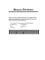
Please include the Manual Number and the Manual Issue,
both shown below, when communicating with Technical
Support regarding this publication.
Title: DirectSOFT 5 Programming Software User Manual
Manual Number:
PC-DSOFT5-M
Issue:
First Edition
Issue Date:
3/06
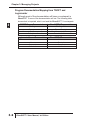
Publication History
Issue
Date
1st Edition
3/06
Description of Changes
Original issue
TABLE OF CONTENTS
Chapter 1: Introduction
Introduction . . . . . . . . . . . . . . . . . . . . . . . . . . . . . . . . . . . . . . .1-2
The Purpose of this Manual . . . . . . . . . . . . . . . . . . . . . . . . . . . . . . . . . . . . .1-2
Who Can and Should Use DirectSOFT 5 . . . . . . . . . . . . . . . . . . . . . . . . . .1-2
Only One DirectSOFT 5 Version . . . . . . . . . . . . . . . . . . . . . . . . . . . . . . . . .1-3
Supplemental Manuals . . . . . . . . . . . . . . . . . . . . . . . . . . . . . . . . . . . . . . . . .1-4
Technical Support . . . . . . . . . . . . . . . . . . . . . . . . . . . . . . . . . . . . . . . . . . . . .1-4
Conventions Used . . . . . . . . . . . . . . . . . . . . . . . . . . . . . . . . .1-5
Menu Selections and Keystrokes . . . . . . . . . . . . . . . . . . . . . . . . . . . . . . . . .1-5
Key Topics for Each Chapter . . . . . . . . . . . . . . . . . . . . . . . . . . . . . . . . . . . .1-5
Chapter 2: Quick Start
Getting to Know Windows . . . . . . . . . . . . . . . . . . . . . . . . . . .2-2
Recommended System Requirements . . . . . . . . . . . . . . . . . . . . . . . . . . . . .2-2
Power Supply . . . . . . . . . . . . . . . . . . . . . . . . . . . . . . . . . . . . . . . . . . . . . . . .2-2
DirectSOFT 5 Package Contents . . . . . . . . . . . . . . . . . . . . . . . . . . . . . . . .2-2
Installation of DirectSOFT 5 . . . . . . . . . . . . . . . . . . . . . . . . .2-3
Getting Started . . . . . . . . . . . . . . . . . . . . . . . . . . . . . . . . . . . .2-8
Welcome to DirectSOFT 100 . . . . . . . . . . . . . . . . . . . . . . . .2-10
Begin Editing a Program . . . . . . . . . . . . . . . . . . . . . . . . . . .2-12
Table of Contents
Establish the Communication Link . . . . . . . . . . . . . . . . . . .2-22
Connect the PC to the PLC . . . . . . . . . . . . . . . . . . . . . . . . . . . . . . . . . . . .2-22
1
Monitor the Program . . . . . . . . . . . . . . . . . . . . . . . . . . . . . .2-28
2
Chapter 3: Managing Projects
3
Started Using DirectSOFT 5 . . . . . . . . . . . . . . . . . . . . . .3-2
D GetUnderstanding
the Launch Window . . . . . . . . . . . . . . . . . . . . . . . . . . . . . . .3-2
5 Create a New Project . . . . . . . . . . . . . . . . . . . . . . . . . . . . . . .3-4
Program . . . . . . . . . . . . . . . . . . . . . . . . . . . . . . . . . . . . . . . . . . . . . . . .3-4
6 New
Enter the New Project Information . . . . . . . . . . . . . . . . . . . . . . . . . . . . . . . .3-4
7 Importing Projects . . . . . . . . . . . . . . . . . . . . . . . . . . . . . . . . .3-5
8 Program Documentation Mapping from TISOFT and Logicmaster . . . . . . .3-6
9 Copy or Save Existing DirectSOFT Files . . . . . . . . . . . . . . .3-7
1 Chapter 4: Programming Environment
11 Offline Toolbar Components . . . . . . . . . . . . . . . . . . . . . . . . .4-2
2 Offline Toolbar . . . . . . . . . . . . . . . . . . . . . . . . . . . . . . . . . . . . . . . . . . . . . . .4-2
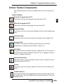
Online Toolbar Components . . . . . . . . . . . . . . . . . . . . . . . . .4-5
13 Online Toolbar . . . . . . . . . . . . . . . . . . . . . . . . . . . . . . . . . . . . . . . . . . . . . . .4-5
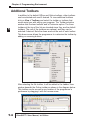
4 Additional Toolbars . . . . . . . . . . . . . . . . . . . . . . . . . . . . . . . .4-6
The File Toolbar . . . . . . . . . . . . . . . . . . . . . . . . . . . . . . . . . . . . . . . . . . . . . .4-7
A The Edit Toolbar . . . . . . . . . . . . . . . . . . . . . . . . . . . . . . . . . . . . . . . . . . . . . .4-8
Search Toolbar . . . . . . . . . . . . . . . . . . . . . . . . . . . . . . . . . . . . . . . . . . .4-9
B The
The View Toolbar . . . . . . . . . . . . . . . . . . . . . . . . . . . . . . . . . . . . . . . . . . . .4-10
C The Tools Toolbar . . . . . . . . . . . . . . . . . . . . . . . . . . . . . . . . . . . . . . . . . . . .4-11
PLC Toolbar . . . . . . . . . . . . . . . . . . . . . . . . . . . . . . . . . . . . . . . . . . . .4-12
D The
The PLC Diagnostics Toolbar . . . . . . . . . . . . . . . . . . . . . . . . . . . . . . . . . . .4-13
The PLC Setup Toolbar . . . . . . . . . . . . . . . . . . . . . . . . . . . . . . . . . . . . . . .4-13
The PLC Setup Toolbar (cont’d) . . . . . . . . . . . . . . . . . . . . . . . . . . . . . . . . .4-14
The Debug Toolbar . . . . . . . . . . . . . . . . . . . . . . . . . . . . . . . . . . . . . . . . . . .4-15
ii
DirectSOFT 5 User Manual, 1st Edition
Table of Contents
The Window Toolbar . . . . . . . . . . . . . . . . . . . . . . . . . . . . . . . . . . . . . . . . . .4-16
The Help Toolbar . . . . . . . . . . . . . . . . . . . . . . . . . . . . . . . . . . . . . . . . . . . .4-17
1
The Custom Toolbar . . . . . . . . . . . . . . . . . . . . . . . . . . . . . . . . . . . . . . . . . .4-17
PLC System Information . . . . . . . . . . . . . . . . . . . . . . . . . . . . . . . . . . . . . .4-19
2
3
D
5
6
7
8
9
0
1
2
3
4
A
B
C
D
Communication/Link Information . . . . . . . . . . . . . . . . . . . . . . . . . . . . . . . .4-20
PLC Mode . . . . . . . . . . . . . . . . . . . . . . . . . . . . . . . . . . . . . . . . . . . . . . . . .4-20
Program Memory Usage . . . . . . . . . . . . . . . . . . . . . . . . . . . . . . . . . . . . . .4-20
PLC Type . . . . . . . . . . . . . . . . . . . . . . . . . . . . . . . . . . . . . . . . . . . . . . . . . .4-20
Program Location . . . . . . . . . . . . . . . . . . . . . . . . . . . . . . . . . . . . . . . . . . . .4-20
The Options Dialog . . . . . . . . . . . . . . . . . . . . . . . . . . . . . . . .4-21
Ladder Options . . . . . . . . . . . . . . . . . . . . . . . . . . . . . . . . . . . . . . . . . . . . . .4-22
Global Options . . . . . . . . . . . . . . . . . . . . . . . . . . . . . . . . . . . . . . . . . . . . . .4-23
Colors in DirectSOFT 5 . . . . . . . . . . . . . . . . . . . . . . . . . . . .4-24
Colors Conveying Information . . . . . . . . . . . . . . . . . . . . . . . . . . . . . . . . . .4-25
Select New Colors . . . . . . . . . . . . . . . . . . . . . . . . . . . . . . . . . . . . . . . . . . .4-26
The Default Settings . . . . . . . . . . . . . . . . . . . . . . . . . . . . . . . . . . . . . . . . . .4-26
Monochrome . . . . . . . . . . . . . . . . . . . . . . . . . . . . . . . . . . . . . . . . . . . . . . .4-26
Select a Theme . . . . . . . . . . . . . . . . . . . . . . . . . . . . . . . . . . . . . . . . . . . . .4-27
The Tool Palette . . . . . . . . . . . . . . . . . . . . . . . . . . . . . . . . . . . . . . . . . . . . .4-28
Be Familiar with the Ladder Palette . . . . . . . . . . . . . . . . . . . . . . . . . . . . . .4-28
The Split Screen Feature . . . . . . . . . . . . . . . . . . . . . . . . . . .4-30
Split Screen Bar . . . . . . . . . . . . . . . . . . . . . . . . . . . . . . . . . . . . . . . . . . . . .4-30
The New Window Feature . . . . . . . . . . . . . . . . . . . . . . . . . .4-31
Chapter 5: Edit a Program
I/O Configuration . . . . . . . . . . . . . . . . . . . . . . . . . . . . . . . . . .5-2
Referencing Program Elements . . . . . . . . . . . . . . . . . . . . . .5-4
Data Types . . . . . . . . . . . . . . . . . . . . . . . . . . . . . . . . . . . . . . . . . . . . . . . . . .5-4
Aliases . . . . . . . . . . . . . . . . . . . . . . . . . . . . . . . . . . . . . . . . . . . . . . . . . . . . .5-5
Timer/Counter Current Values . . . . . . . . . . . . . . . . . . . . . . . . . . . . . . . . . . .5-5
Accessing I/O Points as Memory Locations . . . . . . . . . . . . . . . . . . . . . . . . .5-5
DirectSOFT 5 User Manual, 1st Edition
iii
Table of Contents
Entering Program Instructions . . . . . . . . . . . . . . . . . . . . . . .5-6
The Instruction Editor . . . . . . . . . . . . . . . . . . . . . . . . . . . . . . . . . . . . . . . . . .5-6
1
Using the Ladder Palette . . . . . . . . . . . . . . . . . . . . . . . . . . . . . . . . . . . . . . .5-8
2
3
D
5
6
7
8
9
1
11
2
13
4
A
B
C
D
Opening the Instruction Browser . . . . . . . . . . . . . . . . . . . . . . . . . . . . . . . . .5-8
Shortcuts for Entering Instructions . . . . . . . . . . . . . . . . . .5-11
Entering NO and NC Contacts . . . . . . . . . . . . . . . . . . . . . . . . . . . . . . . . . .5-12
Entering Instructions in Parallel . . . . . . . . . . . . . . . . . . . . . . . . . . . . . . . . .5-13
Entering Power Flow Instructions . . . . . . . . . . . . . . . . . . . . . . . . . . . . . . . .5-14
Entering Special Case Elements . . . . . . . . . . . . . . . . . . . . . . . . . . . . . . . .5-16
End Coil . . . . . . . . . . . . . . . . . . . . . . . . . . . . . . . . . . . . . . . . . . . . . . . . . . .5-17
Setting and Resetting a Bit . . . . . . . . . . . . . . . . . . . . . . . . . . . . . . . . . . . .5-18
Using Floating Point Math . . . . . . . . . . . . . . . . . . . . . . . . . . . . . . . . . . . . .5-18
Drawing/Deleting Connecting Lines . . . . . . . . . . . . . . . . . .5-19
Drawing the Lines . . . . . . . . . . . . . . . . . . . . . . . . . . . . . . . . . . . . . . . . . . .5-19
Create Midline Outputs . . . . . . . . . . . . . . . . . . . . . . . . . . . . . . . . . . . . . . . .5-20
Deleting Connecting Lines . . . . . . . . . . . . . . . . . . . . . . . . . . . . . . . . . . . . .5-20
Selecting Rungs for Deleting, Cutting or Copying . . . . . .5-21
Deleting Rungs . . . . . . . . . . . . . . . . . . . . . . . . . . . . . . . . . . .5-22
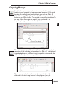
Copying Rungs . . . . . . . . . . . . . . . . . . . . . . . . . . . . . . . . . . .5-23
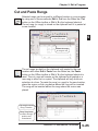
Cut and Paste Rungs . . . . . . . . . . . . . . . . . . . . . . . . . . . . . .5-25
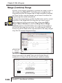
Merge (Combine) Rungs . . . . . . . . . . . . . . . . . . . . . . . . . . .5-26
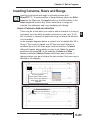
Inserting Columns, Rows and Rungs . . . . . . . . . . . . . . . . .5-27
Insert a Column to Add an Instruction . . . . . . . . . . . . . . . . . . . . . . . . . . . .5-27
Insert a Row or Rung . . . . . . . . . . . . . . . . . . . . . . . . . . . . . . . . . . . . . . . . .5-28
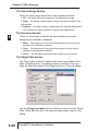
Using Search and Replace . . . . . . . . . . . . . . . . . . . . . . . . .5-29
Using the Object Section . . . . . . . . . . . . . . . . . . . . . . . . . . . . . . . . . . . . . .5-29
The Search Range Section . . . . . . . . . . . . . . . . . . . . . . . . . . . . . . . . . . . .5-30
The Document Section . . . . . . . . . . . . . . . . . . . . . . . . . . . . . . . . . . . . . . . .5-30
The Object Table Section . . . . . . . . . . . . . . . . . . . . . . . . . . . . . . . . . . . . . .5-30
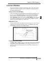
Common Mistakes . . . . . . . . . . . . . . . . . . . . . . . . . . . . . . . .5-31
Failure to Enter the Edit Mode . . . . . . . . . . . . . . . . . . . . . . . . . . . . . . . . . .5-31
iv
DirectSOFT 5 User Manual, 1st Edition
Table of Contents
AND above a Join . . . . . . . . . . . . . . . . . . . . . . . . . . . . . . . . . . . . . . . . . . .5-31
Forgetting to Select Rungs . . . . . . . . . . . . . . . . . . . . . . . . . . . . . . . . . . . . .5-31
1
2
3
D
5
6
7
8
9
0
1
2
3
4
A
B
C
D
Chapter 6: Documentation
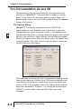
Turn Documentation On and Off . . . . . . . . . . . . . . . . . . . . . .6-2
The Options Dialog . . . . . . . . . . . . . . . . . . . . . . . . . . . . . . . . . . . . . . . . . . .6-2
Documentaion Selections . . . . . . . . . . . . . . . . . . . . . . . . . . . . . . . . . . . . . . .6-3
General Documentaion . . . . . . . . . . . . . . . . . . . . . . . . . . . . . . . . . . . . . . . .6-3
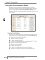
Using the Documentation Editor . . . . . . . . . . . . . . . . . . . . . .6-4
Using the Scroll Buttons . . . . . . . . . . . . . . . . . . . . . . . . . . . . . . . . . . . . . . . .6-4
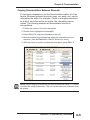
Copying Documentation Between Elements . . . . . . . . . . . . . . . . . . . . . . . .6-5
Documenting and Assigning Nicknames . . . . . . . . . . . . . . .6-6
Create an Unassigned Nickname . . . . . . . . . . . . . . . . . . . . . . . . . . . . . . . .6-6
Assign the Nickname to an Element . . . . . . . . . . . . . . . . . . . . . . . . . . . . . .6-6
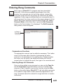
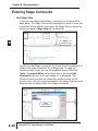
Entering Rung Comments . . . . . . . . . . . . . . . . . . . . . . . . . . .6-9
Comments are Free-form . . . . . . . . . . . . . . . . . . . . . . . . . . . . . . . . . . . . . . .6-9
Selecting Rungs for Comments . . . . . . . . . . . . . . . . . . . . . . . . . . . . . . . . . .6-9
Using the Scroll Buttons . . . . . . . . . . . . . . . . . . . . . . . . . . . . . . . . . . . . . . .6-10
Use the Editing Keys . . . . . . . . . . . . . . . . . . . . . . . . . . . . . . . . . . . . . . . . .6-10
Move Rung Comments . . . . . . . . . . . . . . . . . . . . . . . . . . . . . . . . . . . . . . . .6-11
Entering Stage Comments . . . . . . . . . . . . . . . . . . . . . . . . . .6-12
Use Stage View . . . . . . . . . . . . . . . . . . . . . . . . . . . . . . . . . . . . . . . . . . . . .6-12
Comments are Free-form . . . . . . . . . . . . . . . . . . . . . . . . . . . . . . . . . . . . . .6-13
Selecting Stages to Comment . . . . . . . . . . . . . . . . . . . . . . . . . . . . . . . . . .6-13
Editing the Comments . . . . . . . . . . . . . . . . . . . . . . . . . . . . . . . . . . . . . . . .6-13
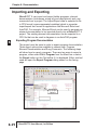
Importing and Exporting . . . . . . . . . . . . . . . . . . . . . . . . . . .6-14
Exporting Program Documentation . . . . . . . . . . . . . . . . . . . . . . . . . . . . . .6-14
Export Element Documentation . . . . . . . . . . . . . . . . . . . . . . . . . . . . . . . . .6-16
Export Rung Comments . . . . . . . . . . . . . . . . . . . . . . . . . . . . . . . . . . . . . . .6-18
Importing a Program . . . . . . . . . . . . . . . . . . . . . . . . . . . . . . . . . . . . . . . . .6-19
Importing Element Documentation . . . . . . . . . . . . . . . . . . . . . . . . . . . . . . .6-22
DirectSOFT 5 User Manual, 1st Edition
v
Table of Contents
Importing Program Comments . . . . . . . . . . . . . . . . . . . . . . . . . . . . . . . . . .6-24
Insert Instructions . . . . . . . . . . . . . . . . . . . . . . . . . . . . . . . . . . . . . . . . . . . .6-24
1
Restore . . . . . . . . . . . . . . . . . . . . . . . . . . . . . . . . . . . . . . . . . . . . . . . . . . . .6-27
2 Prevent Documentation Loss . . . . . . . . . . . . . . . . . . . . . . .6-28
Save Project . . . . . . . . . . . . . . . . . . . . . . . . . . . . . . . . . . . . . . . . . . . . . . . .6-28
3 Backup Project . . . . . . . . . . . . . . . . . . . . . . . . . . . . . . . . . . . . . . . . . . . . . .6-29
D
Chapter 7: Other Views
5
Views . . . . . . . . . . . . . . . . . . . . . . . . . . . . . . . . . . . . .7-2
6 Tabbed
The Primary Views . . . . . . . . . . . . . . . . . . . . . . . . . . . . . . . . . . . . . . . . . . . .7-2
7 Stage (RLL ) View . . . . . . . . . . . . . . . . . . . . . . . . . . . . . . . .7-4
8 Troubleshooting RLL vs. RLL . . . . . . . . . . . . . . . . . . . . . . . . . . . . . . . .7-4
Stage Components . . . . . . . . . . . . . . . . . . . . . . . . . . . . . . . . . . . . . . . . . . . .7-5
9 Mnemonic View . . . . . . . . . . . . . . . . . . . . . . . . . . . . . . . . . . . .7-6
1 Handheld Progammer Aid . . . . . . . . . . . . . . . . . . . . . . . . . . . . . . . . . . . . . .7-6
Reference (XRef) View . . . . . . . . . . . . . . . . . . . . . . . .7-7
11 Cross
XRef Mode . . . . . . . . . . . . . . . . . . . . . . . . . . . . . . . . . . . . . . . . . . . . . . . . . .7-7
2 Change the XRef Query . . . . . . . . . . . . . . . . . . . . . . . . . . . . . . . . . . . . . . . .7-8
Toolbar . . . . . . . . . . . . . . . . . . . . . . . . . . . . . . . . . . . . . . . . . . . . . . . . .7-9
13 XRef
Usage Mode . . . . . . . . . . . . . . . . . . . . . . . . . . . . . . . . . . . . . . . . . . . . . . . .7-10
4 Usage Mode Toolbar . . . . . . . . . . . . . . . . . . . . . . . . . . . . . . . . . . . . . . . . .7-10
XRef DB . . . . . . . . . . . . . . . . . . . . . . . . . . . . . . . . . . . . . . . . . . . . . . . . . . .7-11
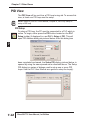
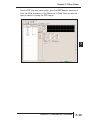
A PID View . . . . . . . . . . . . . . . . . . . . . . . . . . . . . . . . . . . . . . . . .7-12
B PID Setup . . . . . . . . . . . . . . . . . . . . . . . . . . . . . . . . . . . . . . . . . . . . . . . . . .7-12
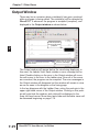
C Output Window . . . . . . . . . . . . . . . . . . . . . . . . . . . . . . . . . . .7-14
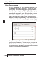
View Terminology . . . . . . . . . . . . . . . . . . . . . . . . . . . . . . . . .7-16
D
PLUS
PLUS
Chapter 8: Printing
Print the Current View . . . . . . . . . . . . . . . . . . . . . . . . . . . . . .8-2
Print the Ladder View . . . . . . . . . . . . . . . . . . . . . . . . . . . . . . . . . . . . . . . . . .8-2
vi
DirectSOFT 5 User Manual, 1st Edition
Table of Contents
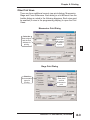
Other Print Views . . . . . . . . . . . . . . . . . . . . . . . . . . . . . . . . . . . . . . . . . . . . .8-3
Print Multiple Views . . . . . . . . . . . . . . . . . . . . . . . . . . . . . . . .8-5
1
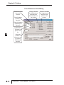
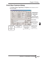
Print View Common Setup . . . . . . . . . . . . . . . . . . . . . . . . . . .8-7
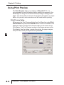
Using Print Preview . . . . . . . . . . . . . . . . . . . . . . . . . . . . . . . .8-8
Print Preview Setup . . . . . . . . . . . . . . . . . . . . . . . . . . . . . . . . . . . . . . . . . . .8-8
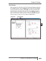
Print Preview . . . . . . . . . . . . . . . . . . . . . . . . . . . . . . . . . . . . . . . . . . . . . . . .8-9
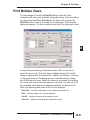
Print Troubleshooting . . . . . . . . . . . . . . . . . . . . . . . . . . . . .8-10
Parts of Program not Printed . . . . . . . . . . . . . . . . . . . . . . . . . . . . . . . . . . .8-10
Program Prints “Garbage” . . . . . . . . . . . . . . . . . . . . . . . . . . . . . . . . . . . . .8-10
DirectSOFT 5 Crashes . . . . . . . . . . . . . . . . . . . . . . . . . . . . . . . . . . . . . . . .8-10
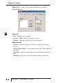
Print Setup Dialog . . . . . . . . . . . . . . . . . . . . . . . . . . . . . . . . . . . . . . . . . . . .8-11
Chapter 9: Setup & Manage Communication
Links
Establish the Communication Link . . . . . . . . . . . . . . . . . . . .9-2
Setup a Serial Link . . . . . . . . . . . . . . . . . . . . . . . . . . . . . . . . .9-2
Link Status . . . . . . . . . . . . . . . . . . . . . . . . . . . . . . . . . . . . . . . . . . . . . . . . . .9-6
Setup an Ethernet Link . . . . . . . . . . . . . . . . . . . . . . . . . . . . .9-7
Setup a Modem Link . . . . . . . . . . . . . . . . . . . . . . . . . . . . . . .9-12
Modem Setup . . . . . . . . . . . . . . . . . . . . . . . . . . . . . . . . . . . . . . . . . . . . . . .9-12
Configuring the Link . . . . . . . . . . . . . . . . . . . . . . . . . . . . . . . . . . . . . . . . . .9-16
Comm Link Options . . . . . . . . . . . . . . . . . . . . . . . . . . . . . . .9-20
Going on Line . . . . . . . . . . . . . . . . . . . . . . . . . . . . . . . . . . . .9-22
Connect the PLC . . . . . . . . . . . . . . . . . . . . . . . . . . . . . . . . . . . . . . . . . . . .9-22
Use the Project Folder . . . . . . . . . . . . . . . . . . . . . . . . . . . . . . . . . . . . . . . .9-22
Use the Link . . . . . . . . . . . . . . . . . . . . . . . . . . . . . . . . . . . . . . . . . . . . . . . .9-22
2
3
D
5
6
7
8
9
0
1
2
3
4
A
B
C
D
Chapter 10: Debugging and Monitoring
Monitor with Data View . . . . . . . . . . . . . . . . . . . . . . . . . . . .10-2
DirectSOFT 5 User Manual, 1st Edition
vii
Table of Contents
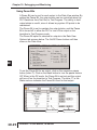
Using Data View . . . . . . . . . . . . . . . . . . . . . . . . . . . . . . . . . . . . . . . . . . . . .10-2
Open a New Data View Window . . . . . . . . . . . . . . . . . . . . . . . . . . . . . . . .10-2
1
2
3
D
5
6
7
8
9
1
11
2
13
4
A
B
C
D
A Closer Look . . . . . . . . . . . . . . . . . . . . . . . . . . . . . . . . . . . . . . . . . . . . . . .10-3
Data View Options . . . . . . . . . . . . . . . . . . . . . . . . . . . . . . . . . . . . . . . . . . .10-4
Select Bits for Display . . . . . . . . . . . . . . . . . . . . . . . . . . . . . . . . . . . . . . . .10-5
Data View Documentation Options . . . . . . . . . . . . . . . . . . . . . . . . . . . . . .10-7
Apply Options . . . . . . . . . . . . . . . . . . . . . . . . . . . . . . . . . . . . . . . . . . . . . . .10-7
Data View Mode Options . . . . . . . . . . . . . . . . . . . . . . . . . . . . . . . . . . . . . .10-8
Make Data View Entries . . . . . . . . . . . . . . . . . . . . . . . . . . . . . . . . . . . . . . .10-8
Data Format and Size . . . . . . . . . . . . . . . . . . . . . . . . . . . . . . . . . . . . . . .10-10
Write the Edits . . . . . . . . . . . . . . . . . . . . . . . . . . . . . . . . . . . . . . . . . . . . .10-11
Auto-increment . . . . . . . . . . . . . . . . . . . . . . . . . . . . . . . . . . . . . . . . . . . . .10-12
Editing Entries . . . . . . . . . . . . . . . . . . . . . . . . . . . . . . . . . . . . . . . . . . . . .10-12
Save the Data View Window . . . . . . . . . . . . . . . . . . . . . . . . . . . . . . . . . .10-13
Using Pause Bits . . . . . . . . . . . . . . . . . . . . . . . . . . . . . . . . . . . . . . . . . . .10-14
Use Override Bits to Control I/O
(DL05/06/240/250-1/260/350/450 Only) . . . . . . . . . . . . . . . . . . . . . . . . . .10-15
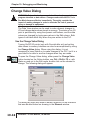
Change Value Dialog . . . . . . . . . . . . . . . . . . . . . . . . . . . . .10-16
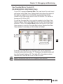
Use the Change Value Dialog . . . . . . . . . . . . . . . . . . . . . . . . . . . . . . . . .10-16
Specify an Element Reference or Nickname . . . . . . . . . . . . . . . . . . . . . .10-17
Enter a New Value . . . . . . . . . . . . . . . . . . . . . . . . . . . . . . . . . . . . . . . . . .10-18
Using the Memory Editor . . . . . . . . . . . . . . . . . . . . . . . . . .10-20
Select the Locations to View . . . . . . . . . . . . . . . . . . . . . . . . . . . . . . . . . .10-20
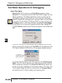
Test Mode Operations for Debugging . . . . . . . . . . . . . . .10-22
Select Test Mode . . . . . . . . . . . . . . . . . . . . . . . . . . . . . . . . . . . . . . . . . . .10-22
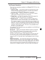
Test Program Operations . . . . . . . . . . . . . . . . . . . . . . . . . . . . . . . . . . . . .10-23
The Test Operations Window . . . . . . . . . . . . . . . . . . . . . . . . . . . . . . . . . .10-24
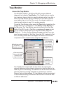
Trap Monitor . . . . . . . . . . . . . . . . . . . . . . . . . . . . . . . . . . . .10-25
Access the Trap Monitor . . . . . . . . . . . . . . . . . . . . . . . . . . . . . . . . . . . . .10-25
Use with Data View . . . . . . . . . . . . . . . . . . . . . . . . . . . . . . . . . . . . . . . . .10-27
Stack Monitor (DL440 Only) . . . . . . . . . . . . . . . . . . . . . . . .10-28
Access the Stack Monitor . . . . . . . . . . . . . . . . . . . . . . . . . . . . . . . . . . . . .10-28
viii
DirectSOFT 5 User Manual, 1st Edition
Table of Contents
Check DirectSOFT 5 File Revision . . . . . . . . . . . . . . . . . .10-29
Appendix A: Protocols and Cable Diagrams
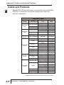
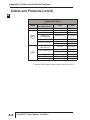
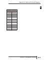
Cables and Protocols . . . . . . . . . . . . . . . . . . . . . . . . . . . . . .A-2
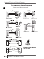
Programming Cable Diagrams . . . . . . . . . . . . . . . . . . . . . . .A-6
AppendixB: Communications
Troubleshooting
DS500.ini File . . . . . . . . . . . . . . . . . . . . . . . . . . . . . . . . . . . . .B-2
DS500.ini File . . . . . . . . . . . . . . . . . . . . . . . . . . . . . . . . . . . . . . . . . . . . . . . .B-2
Enable Dump=1 . . . . . . . . . . . . . . . . . . . . . . . . . . . . . . . . . . . . . . . . . . . . . .B-3
Enable AutoSense=0 . . . . . . . . . . . . . . . . . . . . . . . . . . . . . . . . . . . . . . . . . .B-4
Startup Issues . . . . . . . . . . . . . . . . . . . . . . . . . . . . . . . . . . . . . . . . . . . . . . .B-4
Other Issues . . . . . . . . . . . . . . . . . . . . . . . . . . . . . . . . . . . . . .B-5
USB-to-Serial Converters . . . . . . . . . . . . . . . . . . . . . . . . . . . . . . . . . . . . . .B-5
Microsoft ActiveSync . . . . . . . . . . . . . . . . . . . . . . . . . . . . . . . . . . . . . . . . . .B-5
DirectSOFT 5 User Manual, 1st Edition
ix
1
2
3
D
5
6
7
8
9
0
1
2
3
4
A
B
C
D
INTRODUCTION
CHAPTER
1
In This Chapter
Introduction . . . . . . . . . . . . . . . . . . . . . . . . . . . . . . . . . . .1-2
Conventions Used . . . . . . . . . . . . . . . . . . . . . . . . . . . . . .1-5
Chapter 1: Introduction
Introduction
1
2
3
D
5
6
7
8
9
1
11
2
13
4
A
B
C
D
The Purpose of this Manual
This manual describes how to use the DirectSOFT 5 software for
programming and monitoring any of the DirectLogic and compatible
CPUs. This manual will not teach you how to develop a relay
ladder logic (RLL) program or attempt to familiarize you with
the instruction sets of the CPUs. Please refer to the applicable
PLC user manual for the RLL instructions. The Quick Start chapter
will show the first time user how to get started using DirectSOFT 5.
The balance of the manual will detail all of the programming tools
made available to the user.
Who Can and Should Use DirectSOFT 5
If you have a PLC belonging to the DirectLOGIC CPU family, you
can use DirectSOFT 5 to manage your existing ladder logic
programs and to create new ones. The families of PLCs that
currently exist under this description are shown below.
DirectLOGIC PLC Family
DL06 CPUs
Two built-in ports
Max. baud = 38.4 K
DL05 CPUs
Two built-in ports
Max. baud = 38.4 K
DL105 CPUs
One built-in port
Fixed baud = 9.6 K
DL205 CPUs
One built-in port D2-230; fixed baud = 9.6 K
Two built-in ports D2-240; max. baud = 19.2 K
Two built-in ports D2-250(-1)/260 max baud =38.4 K
DL305 CPUs
D3-330 requires D3-232-DCU; max. baud = 19.2 K
Two built-in ports D3-340/350; max. baud = 38.4 K
DL405 CPUs
Two built-in ports D4-430/440; max baud = 19.2 K
Four built-in ports D4-450; max. baud = 38.4 K
1-2
DirectSOFT 5 User Manual, 1st Edition
Chapter 1: Introduction
Besides being easy to use, DirectSOFT 5 includes the following
features:
1
• Dockable/Floating Views - includes Cross Reference, Data Views and
Output window.
• New look and feel - new toolbar button icons, new toolbars and
completely configurable toolbars.
• Tabbed main views (ladder, stage, documentation editor).
• Online Status Bar is now integrated as part of the primary status bar on
the bottom of the application. Also, each online status bar field is a
“button” which will bring up an appropriate dialog (the mouse can be
floated over each of the fields to show a tool-tip to show what it will do).
• User Interface (UI) Themes allows you to give DirectSOFT 5 a certain UI
feel (Office XP, Office 2003, Mac, et.al.).
• Export Data View allows you to export the information in the Data View
Element and Status columns in CSV (comma separated variable) format,
for a minimal logging capability.
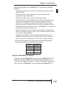
• Intelligent Boxes (IBoxes) are modularized/parameterized blocks of
ladder logic that perform common, simple, but also some complex PLC
logic. These will only download to the PLCs with the proper firmware.
See the chart below for the PLCs and the supporting firmware
revisions required for the new IBox instructions.
PLC
Firmware
DL05
DL06
D2-250-1
D2-260
D4-450
5.10
2.10
4.60
2.40
3.30
Only One DirectSOFT 5 Version
There is only one DirectSOFT 5 version for the DirectLOGIC PLC
family. All versions of DirectSOFT programming software (v1.0 v4.0) can be upgraded to version 5. Also, all programs created with
older versions of DirectSOFT are compatible with DirectSOFT 5.
DirectSOFT 5 User Manual, 1st Edition
2
3
D
5
6
7
8
9
0
1
2
3
4
A
B
C
D
1-3
Chapter 1: Introduction
Supplemental Manuals
1
2
3
D
5
6
7
8
9
1
11
2
13
4
A
B
C
D
1-4
Depending on the products you have purchased, there may be other
manuals that are necessary to use for your application.
User Manuals
• DL05 User Manual Ҁ D0-USER-M
• DL06 User Manual Ҁ D0-06USER-M
• DL105 User Manual Ҁ D1-USER-M
• DL205 User Manual Ҁ D2-USER-M
• DL305 User Manual Ҁ D3-USER-M
• DL350 User Manual Ҁ D3-350-M
• DL405 User Manual Ҁ D4-USER-M
NOTE: AutomationDirect also has many associated product user manuals,
such as analog manuals, which will assist you with your application.
Technical Support
We realize that even though we strive to do our best, we may have
arranged our information in such a way that you cannot find what
you are looking for. First, check these resources for help in locating
the information:
• Table of Contents – chapter and section listing of contents, in the front of
this manual
• Appendices – reference material for key topics, near the end of this
manual
• Index – reference for key items
You can also check our online resources for the latest product
support information:
• Internet – the address of our website is:
http://www.automationdirect.com
If you still need assistance, please call us at 770–844–4200. Our
technical support team will be available to work with you to answer
your questions. They are available Monday through Friday from 9:00
A.M. to 6:00 P.M. Eastern Standard Time. If you have a comment or
question about any of our products, services, or manuals, please fill
out and return the ‘Suggestions’ card that was shipped with this
manual.
DirectSOFT 5 User Manual, 1st Edition
Chapter 1: Introduction
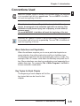
Conventions Used
When the “notepad” symbol is shown in the left-hand margin, the paragraph
to its immediate right will be a special note. The word NOTE: in boldface
will mark the beginning of the text.
When the “exclamation mark” symbol is shown in the left-hand
margin, the paragraph to its immediate right will be a warning. This
information could prevent injury, loss of property, or even death (in
extreme cases).
The word WARNING: in boldface will mark the beginning of the text.
Whenever the “lightbulb” is shown in the left-hand margin, the paragraph to
its immediate right will provide a special tip. The word TIP: in boldface will
mark the beginning of the text.
Menu Selections and Keystrokes
When the software requires you to use a particular keystroke or
menu selection, the written instructions will be in boldface type.
Combination keystrokes will be separated with a plus (+) sign. For
example, Ctrl + C means: Hold down the Ctrl key and press the C
key. Menu selections can also be combinations and separated by a
greater-than sign. For example, File > Write Program > to Disk is
a menu selection combination.
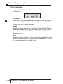
Key Topics for Each Chapter
The beginning of each chapter will list the
key topics that can be found in that
chapter.
DirectSOFT 5 User Manual, 1st Edition
1
2
3
D
5
6
7
8
9
0
1
2
3
4
A
B
C
D
1-5
CHAPTER
QUICK START
2
In This Chapter:
Getting to Know Windows . . . . . . . . . . . . . . . . . . . . . . .2-2
Installation of DirectSOFT 5 . . . . . . . . . . . . . . . . . . . . .2-3
Getting Started . . . . . . . . . . . . . . . . . . . . . . . . . . . . . . .2-8
Welcome to DirectSOFT100 . . . . . . . . . . . . . . . . . . .2-10
Begin Editing a Program . . . . . . . . . . . . . . . . . . . . . . .2-12
Establish the Communication Link . . . . . . . . . . . . . . .2-22
Monitor the Program . . . . . . . . . . . . . . . . . . . . . . . . . .2-28
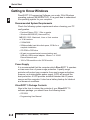
Quick Start
Getting to Know Windows
1
2
3
D
5
6
7
8
9
1
11
2
13
4
A
B
C
D
2-2
DirectSOFT 5 Programming Software runs under 32-bit Windows
operating systems (98/2000/NT/XP). It’s a good idea to understand
the operating system for your computer.
Recommended System Requirements
Check the following system requirements when choosing your PC
configuration.
• Pentium/Celeron CPU, 1 Ghz or greater
• Windows 98/2000/XP (Home and Pro)
NO DOS, OS/2, Macintosh, Linux or Unix versions
or 16 bit versions
• 512Mb RAM
• 20Mb available hard drive disk space, 33 Mb for a
complete installation.
• CD-ROM or DVD drive
• At least one unused serial communications port,
USB with USB-to-serial adapter, 10base-T or 10/100
Eternet Network card
• 1024 x 768 resolution color SVGA monitor
Power Supply
It is recommended that the computer which DirectSOFT 5 operates
on has some form of power surge protection. A quality surge
protector will protect your computer from most surges and spikes;
however, an uninterruptible power supply (UPS) will provide the
best protection. A UPS provides isolation between the AC power
source and the computer. It also has a battery backup for blackout
and brownout conditions.
DirectSOFT 5 Package Contents
Now is the time to review the contents of your DirectSOFT 5
software package. you should have the following items:
• CD ROM
• Programming User Manual
DirectSOFT 5 User Manual, 1st Edition
Quick Start
Installation of DirectSOFT 5
1
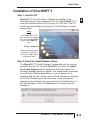
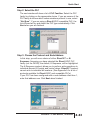
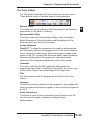
Step 1: Load the CD
DirectSOFT 5 for PLCs Server Software is available on the
AutomationDirect Product Showcase CD. To install DirectSOFT 5,
insert the AutomationDirect CD into your PC’s CD drive. The CD
should start automatically and open the “Install Software” window
shown below.
Note:
If the DirectSOFT 5 CD
does not start automatically,
go to the Windows START
button, select RUN and
type:
E:\ADC_catalog.exe
Change the letter E above
to match your CD drive.
Then click on OK and the
program will start.
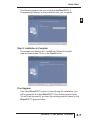
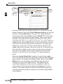
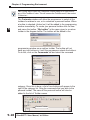
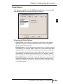
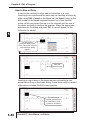
Step 2: Select the Install Software Option
The DirectSOFT 5 “Install Software” window offers all the options
available with this CD. To install DirectSOFT 5, select the Install
Purchased Software option indicated on the figure above. The
following message dialog will appear. This dialog issues a reminder
to exit all other Window applications. If you are unsure of the
programs that may be running, open the Task Manager by pressing
the Ctrl-ALT-Delete keys at the same time. Close any opened
applications by selecting them and clicking on the Close button of
the Task Manager. Click on the Next button to proceed with the
installation.
DirectSOFT 5 User Manual, 1st Edition
2
3
D
5
6
7
8
9
0
1
2
3
4
A
B
C
D
2-3
Quick Start
Step 3: Enter the Product Key Code
1
2
3
D
5
6
7
8
9
1
11
2
13
4
A
B
C
D
From this window, enter the Product Key that was e-mailed to you,
or phone 1-800-633-0405 and get the Product Key from either sales
or technical support if you did not receive it. This software package
is protected by this Product Key code. Only licensed users that
have a Product Key code may install the software. After entering the
Product Key click the Next button.
Enter
Product Key
here
Then click on
the Next button
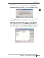
Step 4: Installing an Upgrade
If you are installing the DirectSOFT 5 upgrade version, setup will
search your PC to look for a previous version of DirectSOFT. If a
previous DirectSOFT version is not found, you will be prompted to
enter a valid product key code from a previous version of
DirectSOFT.
Click here to proceed with
the DirectSOFT 5 installation
2-4
DirectSOFT 5 User Manual, 1st Edition
Quick Start
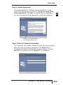
Step 5: License Agreement
The wizard displays the “Software License Agreement” shown
below. Read the agreement and select I accept the terms of the
license agreement. Click Next to continue with the installation. If
you do not accept the license agreement, cancel the installation.
1
Click here if you agree with the
License Agreement’s terms.
Step 6: Enter the Customer Information
The “Customer Info” window requests the user name and company.
Enter the name of the person assigned to the DirectSOFT 5
Programming Software and the name of your company. Click the
Next button to continue with the DirectSOFT 5 installation.
DirectSOFT 5 User Manual, 1st Edition
2
3
D
5
6
7
8
9
0
1
2
3
4
A
B
C
D
2-5
Quick Start
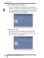
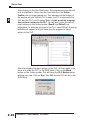
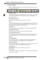
Step 7: Select the Type of Installation
1
2
3
D
5
6
7
8
9
1
11
2
13
4
A
B
C
D
2-6
The wizard now displays the “Setup Type” window. This window
allows you to select either the “Complete” or the “Custom” type of
installation. Complete is the most common selection. Custom allows
you to select the optional components you want. It is recommended
that you select Complete for your DirectSOFT 5 installation. Click
on the Next button to proceed with installation.
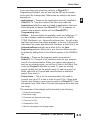
Step 8: Ready to Install
The wizard continues with the “Ready to Install the Program”
window appears. Verify the folder name where the DirectSOFT 5
files are to be stored. If this is the desired folder, click on the Next
button to continue with the installation.
DirectSOFT 5 User Manual, 1st Edition
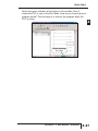
Quick Start
The following window lets you know that the DirectSOFT 5
Programming Software is being installed onto your computer.
1
Step 9: Installation is Complete
The wizard now displays the “InstallShield Wizard Complete”
window shown below. Click on the Finish button.
If an Upgrade
If an older DirectSOFT version is found during the installation, you
will be prompted to make DirectSOFT 5 the default projects folder.
You will then be asked if you want the existing projects copied to the
DirectSOFT 5 projects folder.
DirectSOFT 5 User Manual, 1st Edition
2
3
D
5
6
7
8
9
0
1
2
3
4
A
B
C
D
2-7
Quick Start
Getting Started
1
2
3
D
5
6
7
8
9
1
11
2
13
4
A
B
C
D
2-8
Before beginning to edit a program, you need to open
DirectSOFT 5. If you are already familiar with
DirectSOFT, click on the DirectSOFT 5 icon located on
your desktop screen to open the DSLaunch window. You
can also click on Start located in the left-hand corner of the
computer monitor. Now select Programs, find DirectSOFT 5, then
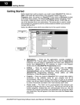
select DSLAUNCH 5 in the drop-down window. The following
DSLAUNCH window will appear.
Windows-type
Menu Tree
Utilities, such
as NetEdit
Installed
Support
Communication
Links to PLCs
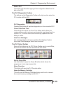
From this window, additional utilities, such as, NetEdit, CTRIO WB,
etc., can all be launched from one central location. This is also used
to create and manage PLC programs and the communications links
between your personal computer and the PLC.
Notice the different areas which are pointed out in the launch
window.
NOTE: Also see DSLAUNCH comments in Chapter 3.
DirectSOFT 5 User Manual, 1st Edition
Quick Start
If you have been using previous versions of DirectSOFT
Programming Software, you will see that the DSLaunch window
looks much like it always has. Differences are noted in the below
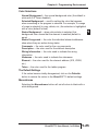
descriptions:
• Applications 앥 These are the applications currently installed in
DirectSOFT5. They are visible in the Menu tree under the
Applications folder/icon and are linked to applications that have
been designed for launch from DirectSOFT 5. For example, to
create a new program, double-click the DirectSOFT 5
Programming name.
• Utilities 앥 Several utilities are available under this folder/icon. If
you have already installed available utilities, such as, NetEdit,
CTRIO Workbench, etc., these will be shown here. You will notice
that there are three new utilities available, a shortcut to Microsoft®
Calculator that comes with Microsoft® Windows, a direct link to the
AutomationDirect website and a direct link to the Host
Engineering website. Shortcuts to your favorite utilities can also
be added by adding them to the Utililities section of the DS500.ini
file.
• Projects 앥 These are the programs which are created in
DirectSOFT 5. A project is the collective name for your program
and all of its documentation. When you create a new project or
work on an existing project, you will see it listed in the Menu Tree
under the Projects folder/icon by name. To open an existing
project, double-click on the project name. To open a project not
listed, right-click on Projects and select Browse to locate the
project, then select it.
• Comm Links 앥 This is for the communication links used to
connect from your PC to one or more of your PLCs. If there were
Comm Links existing in your previous version of DirectSOFT, they
will appear here. New Comm Links will also appear here after they
are setup.
The remainder of this chapter will be devoted to the following:
1. Create a new program.
2. Add some rungs.
1
2
3
D
5
6
7
8
9
0
1
2
3
4
A
B
C
D
3. Document the elements and rungs.
4. Connect to a PLC.
5. Download to a PLC.
6. Monitor the program and change status.
DirectSOFT 5 User Manual, 1st Edition
2-9
Quick Start
Welcome to DirectSOFT100
1
2
3
D
5
6
7
8
9
1
11
2
13
4
A
B
C
D
2-10
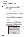
NOTE: If you have purchased the full version of DirectSOFT 5, go to page
2-12, Begin Editing a Program.
If you have loaded the free version of DirectSOFT 5, you should
know what you can and cannot do with the software.
What is DirectSOFT100?
The DirectSOFT100 software is provided as a solution for small
applications and to assist in your decision to purchase the full
DirectSOFT 5 programming software. There are, of course,
limitations to the use of DirectSOFT100. The following is what you
can and cannot do with the software:
• You CAN create a program from scratch, and it can be as large as you
want it to be.
• You CAN save programs larger than 100 words to disk, but you CANNOT
write it to the PLC.
• You CAN convert DirectSOFT100 version to the full version if you
purchase the key and enter the key code in the DirectSOFT100
dialog (it may appear often) or in the Help > About dialog.
• You CANNOT download a program to a PLC larger than 100 words.
• You CANNOT open an offline project larger than 100 words.
• You CANNOT open a program in the PLC larger than 100 words.
There are no other limitations. DirectSOFT100 is able to use all of
the features described in this manual. Many instances of
DirectSOFT100 can be running at one time and monitor any
number of data points. DirectSOFT100 is basically the same,
functionally, as DirectSOFT 5 (full version) except the ladder
program needs to remain within 100 words.
DirectSOFT 5 User Manual, 1st Edition
Quick Start
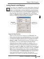
Using DirectSOFT100?
To begin a project, double-click on DirectSOFT 5 Programming
under Applications on the menu tree. The following Welcome to
DirectSOFT100 window will appear.
1
Click here to
begin a project.
Click on Run DirectSOFT100 and the New Project dialog will open
as shown on page 2-12. You can now begin to edit a program
following from Step 1.
DirectSOFT 5 User Manual, 1st Edition
2
3
D
5
6
7
8
9
0
1
2
3
4
A
B
C
D
2-11
Quick Start
Begin Editing a Program
1
2
3
D
5
6
7
8
9
1
11
2
13
4
A
B
C
D
2-12
You can now begin editing your program. The following steps will
show you the basics of editing with DirectSOFT 5. This will not be
an attempt to teach you how to develop a control program, but it will
give you the basics to get started using DirectSOFT 5 so that you
can edit a program.
Step 1: Start a New Project
To begin a new project, double-click DirectSOFT 5 Programming
under Applications in the menu tree. The following window will
appear. The New Project window is used to enter the basic
information to begin a new project. Name the new project, then
move the cursor to the Family area and select the PLC family to
match the PLC that you are using. Next, select the CPU type. Once
all of the information has been entered, click on OK. Keep in mind
that the available mnemonics, processing rules and the tool bar
characteristics are tailored to the Family and Type selections that
you make.
Use this to start
a new project or
to open an
existing project.
New Project window
...click on OK
Type a new name
Select the PLC Family
DirectSOFT 5 User Manual, 1st Edition
Select the CPU Type
Quick Start
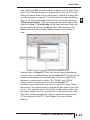
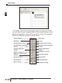
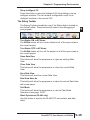
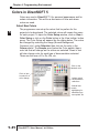
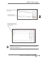
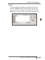
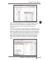
After clicking on OK, the next window to appear is the Ladder View
with a Tip of the Day dialog box as seen below. The Tip of the Day
dialog will appear each time a new project is started, and each time
an existing project is opened. If it is not desired to have this dialog
“pop-up” as mentioned, simply click off the check mark preceding
“Show tips at startup”. The tips dialog can always be opened by
clicking on Help > Tip of the day on the main menu bar. More tips
can be read by clicking on the Next button. After clicking on the
Close button the new Program display window will be totally in
view.
Show tips at startup
Regular users of DirectSOFT will note that the new programming
window looks a bit different than previous DirectSOFT programming
software (see diagram on the next page). This is the default look
whenever a new project is started. The “Online” and “Offline”
toolbars have the same layout as previous DirectSOFT
programming windows but a new look for the button icons. Notice
that some of the toolbar icons are grayed-out and some of the icons
are not. The available icons in the online toolbar will be visible. As a
program is edited, more of the grayed-out icons will become visible.
The online toolbar is grayed-out and will remain this way until the
PC is connected to the PLC. See Chapter 4 for more toolbar
features.
DirectSOFT 5 User Manual, 1st Edition
1
2
3
D
5
6
7
8
9
0
1
2
3
4
A
B
C
D
2-13
Quick Start
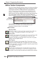
Offline
Toolbar
1
2
3
D
5
6
7
8
9
1
11
2
13
4
A
B
C
D
2-14
Edit Mode
buttons
Push-pin
Online
Toolbar
Drag
bar
Cursor
Ladder Palette Bar
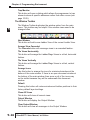
By default, there are two windows that will be in view when a new
project is opened. One is the Cross Reference View on the left and
the other is the Ladder View on the right. The Cross Reference
View is one of the new dockable views in DirectSOFT 5 which also
includes Data Views and the Output window. These views can be
docked to any edge of the Programming Window or they can be
undocked and “float” to any part of the screen, even onto a different
display if you have multiple monitors. If the view is docked, you can
“auto-hide” the view by clicking on the push-pin in the upper righthand corner of the view. The view will auto-hide to the left of the
Ladder View with the name of the view on the tab. To bring the view
from auto-hide, hold the mouse cursor over the name in the tab. If
the view is not needed, click on the X located to the right of the
push-pin to close the view. See Chapter 7 to learn more about
views.
Notice the Ladder Palette Bar located to the right of the Ladder
View. The element buttons are grayed-out unless the Edit Mode has
been activated. To activate the Ladder Palette, click on either EDIT
Mode button; one is located on the Offline toolbar and one is
located at the top of the Ladder Palette. This palette can be
repositioned anywhere on the screen by “grabbing” it with the
mouse pointer at the top of the palette and dragging it to a new
position. The Ladder Palette contains the buttons that access the
rung elements and operations commonly used when editing ladder
logic programs.
DirectSOFT 5 User Manual, 1st Edition
Quick Start
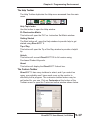
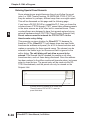
The diagram below shows a newly opened Display window with the
Cross Reference View in the auto-hide position and the Ladder
View in full view.
Cross Reference View
in auto-hide position
It is good practice to leave the Cross Reference View open while
editing your program. The rung elements are added to the Cross
Reference View as the program is accepted.
Accepting a program will be discussed later in this chapter.
NOTE: The Cross Reference View can be retrieved by going to View on
the Menu Bar and select it from the drop-down menu, then click on the
push-pin to keep it in view.
Step 2: Select Edit Mode
The ladder View has two viewing modes; the Display Mode and the
Edit Mode. When a new program or an existing program is opened,
the Ladder View will be in the Display Mode which is only a viewing
mode. A program cannot be edited in this mode. In order to edit a
program, you must be in the Edit Mode. To enable the Edit Mode,
either click on the Edit Mode button on the Offline toolbar or click on
the Edit Mode button on the Ladder Palette Bar. You will know when
the Edit Mode is active when the cursor box becomes solid, a box
appears around the Edit Mode buttons and the elements in the
Ladder Palette are highlighted.
DirectSOFT 5 User Manual, 1st Edition
1
2
3
D
5
6
7
8
9
0
1
2
3
4
A
B
C
D
2-15
Quick Start
1
2
3
D
5
6
7
8
9
1
11
2
13
4
A
B
C
D
2-16
Edit Mode
(solid cursor box)
The Ladder Palette shown facing page may not be exactly like the
one you have on your computer screen. The elements shown in the
palette will depend on which CPU your PLC is using. This example
shows the elements common to all the CPUs.
Toolbar Options
Close view
Edit Mode
Accept
Normally Open Contact
Normally Closed Contact
Normally Open Immediate
Contact
Normally Closed Immediate
Contact
Positive Differential
Contact
Equal to Contact
Equal to or Greater Than
Contact
Negative Differential
Contact
Browse Contacts
Browse Coils
Browse Boxes
Browse Elements
Wire to Output
Wrap Wire to Stage
DirectSOFT 5 User Manual, 1st Edition
Not Equal to Contact
Less Than Contact
Quick Start
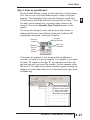
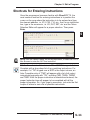
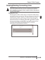
Step 3: Enter an Input Element
Use the Ladder Palette to enter the first instruction of the program.
First, click on one of the Edit Mode buttons to begin to edit your
program. The rectangular edit cursor will change to a solid color.
The edit cursor should be positioned to the far left on Rung 1. Your
first entry can be placed here, normally a relay contact or an
element. Click on the Normally Open Contact symbol on the
palette.
The cursor will change to a box with an open relay contact, a
window with the text cursor blinking at the end of address C0
(highlighted) and green, valid entry, indicators.
Open the
Element Browser
Enter the
contact
Valid entry
indicators
Delete the
edit box
Default
address
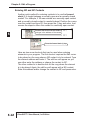
If the green dot changes to red, it means that the address is
incorrect, not valid or a wrong character. For example, if you typed
the letter “O” instead of the digit “0”, the indicator would turn red
and stay red until you correct the mistake. For this example, enter
X0 over C0. The valid entry indicator should be green meaning the
address is correct. Now, either click on the check mark (冑冑) or press
the Enter key.
Enter X0
Notice the Valid entry
indicator will be green
when a valid contact
address is entered
DirectSOFT 5 User Manual, 1st Edition
1
2
3
D
5
6
7
8
9
0
1
2
3
4
A
B
C
D
2-17
Quick Start
1
2
3
D
5
6
7
8
9
1
11
2
13
4
A
B
C
D
2-18
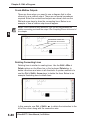
The element will be entered and the coursor will move to the next
entry position. A yellow vertical bar will appear to the left of the left
of Rung 1. Since this is not a color manual, a light colored vertical
bar is seen in the example. The yellow bar indicates that an
instruction (or instructions) has been entered, but the program has
not been accepted (compiled).
Yellow
colored bar
indicates the
rung has not
been
accepted.
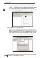
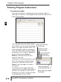
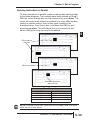
Step 4: Enter an Output Element
Now, move the cursor to the end of the rung, positioned over the
NOP. Click on the Browse Coils button on the Ladder Palette. The
Instruction Browser will appear with the Standard Coil selected
as the default. Click OK to enter the standard coil. Keep in mind
that one of the other output coils could have been selected.
DirectSOFT 5 User Manual, 1st Edition
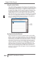
Quick Start
The Instruction Browser will be replaced with the element entry box.
The default address, C0, will be highlighted. Enter Y0 and notice the
valid entry indicator is green for a proper entry. Either click on the
(冑冑) or press the Enter key to enter the output coil.
Enter Y0 here
Rung 1 has now been programmed. This rung can be downloaded
to the PLC except for one missing rung. All programs must be
terminated with an END Coil rung.
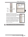
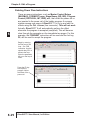
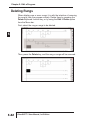
Step 5: Enter the End Rung
To program this rung, position the cursor so it is over the NOP at
the end of Rung 2, and click on the Browse Coils button. The
Instruction Browser will appear as shown in the diagram below. This
time, select Program Control located in the Coil Class selection
window. Next, select END located in the Coils selection window.
Click on OK, then Enter.
DirectSOFT 5 User Manual, 1st Edition
1
2
3
D
5
6
7
8
9
0
1
2
3
4
A
B
C
D
2-19
Quick Start
1
2
3
D
5
6
7
8
9
1
11
2
13
4
A
B
C
D
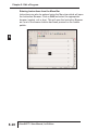
2-20
The below diagram shows the two rungs that have been
programmed. This is a basic program that can be downloaded to
your PLC. Additional rungs can be programmed, but you can go
ahead and accept the program
Step 6: Accepting and Saving the Program
The program now needs to be accepted in order to be downloaded
to the PLC. As noted in the above diagram, there are two Accept
buttons. Click on either Accept button to compile the program. Once
the rungs are accepted with no errors, the yellow bar will change to
green, the Accept buttons will be grayed-out and the Cross
Reference View now shows the two elements that have been
programmed.
Read and
Write buttons
Programmed
elements now
appear in the Cross
Reference View
DirectSOFT 5 User Manual, 1st Edition
Green bar
indicates the rung
has been accepted.
Quick Start
Notice that the two Read and Write buttons located to the left of the
Offline toolbar are enabled and no longer grayed-out. The program
can now be saved to the PC’s disk. To write the program to disk,
click on the Write button. It is not necessary to save the program in
order to download the program to the PLC, however, it is good
practice to save your work as you edit a program. A mistake may
be made at times and you may want to restore the program to the
state that it was before the mistake was made. If a mistake is made
and you want to restore the program, click on the Read button. This
will refresh the screen with the previously saved version of your
program.
NOTE: When the program is saved by clicking on the Write (only to disk),
the ladder program is all that is saved. Once you have edited a program
and have included total documentaion, you will want to save all that you
have done. This is accomplished by selecting File > Save Project > to disk.
You can also click on Backup to accomplish the same thing with the
addition of a Backup file. For more detail about documenting and saving the
project refer to Chapter 6.
DirectSOFT 5 User Manual, 1st Edition
1
2
3
D
5
6
7
8
9
0
1
2
3
4
A
B
C
D
2-21
Quick Start
Establish the Communication Link
1
2
3
D
5
6
7
8
9
1
11
2
13
4
A
B
C
D
2-22
In order to download a program to the PLC a communication link
must be established. This section will step you through the
procedure for setting up the serial port of your PC. Refer to Chapter
9 if you need to create a serial link for a modem, or an Ethernet link.
The following procedure will step you through the process of
connecting the example program to a PLC.
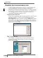
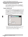
Connect the PC to the PLC
Connect the programming cable from the serial port of the PC to the
serial port of the PLC. Turn on your PLC and be sure that the
RUN\TERM\STOP switch on the PLC is in the TERM position. Now,
click on PLC on the Menu Bar, then select Connect from the dropdown menu and the Select Link dialog will appear. Since there isn’t
a link to chose, click on Add.
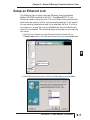
Step 1: Select the Port
The following Link Wizard dialog will appear showing a list of
communication ports. Select the port you will use (commonly
COM1) and click Next.
DirectSOFT 5 User Manual, 1st Edition
Quick Start
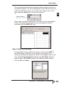
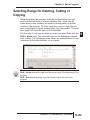
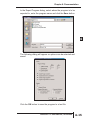
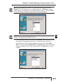
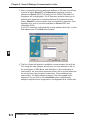
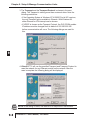
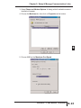
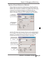
Step 2: Select the PLC
The next window will show a list of PLC Families. Select the PLC
family by clicking on the appropriate choice. If you are unsure of the
PLC family but know which communications protocol to use, select
“Not Sure”. If you are using a DirectLOGIC compatible PLC, the
Link Wizard will try and detect the PLC type automatically. Click
Next when you are finished.
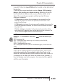
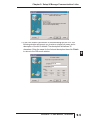
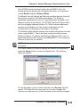
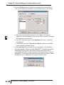
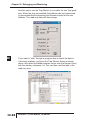
Step 3: Choose the Protocol and Node Address
In this step, you will see a choice of either DirectNET or KSequence. Assuming you have selected the DirectLOGIC PLC
family (not the DL305), the default, K-Sequence, will be highlighted.
The K-Sequence protocol allows you to perform write operations to
individual discrete I/O points and control relays. DirectNET protocol
cannot write to individual bit locations. (See Appendix A for a list of
protocols available for DirectLOGIC and compatible PLCs).
If your PLC has been configured with a node address other than 1,
enter that address now. Click Next when finished.
DirectSOFT 5 User Manual, 1st Edition
1
2
3
D
5
6
7
8
9
0
1
2
3
4
A
B
C
D
2-23
Quick Start
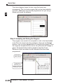
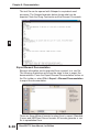
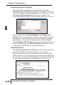
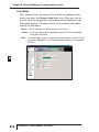
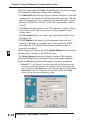
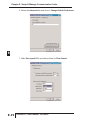
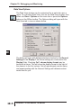
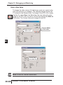
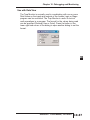
Step 4: Name the Link
1
2
3
D
5
6
7
8
9
1
11
2
13
4
A
B
C
D
2-24
If the Link Wizard is successful in communicating with the PLC, the
following window will prompt you to enter a unique link name, and a
description of the link if desired. The description field allows 32
characters. Enter the name for the link and description then click
Finish and the Select Link dialog will appear with the link name
listed.
Since the link that was just created is the only one named in the
dialog, click on Select to initiate connecting to the PLC.
DirectSOFT 5 User Manual, 1st Edition
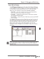
Quick Start
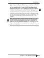
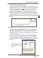
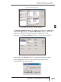
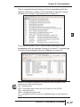
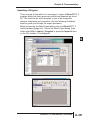
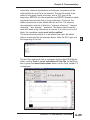
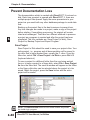
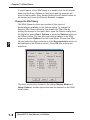
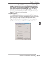
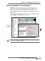
DirectSOFT 5 automatically compares the currently open program
with the program stored in the PLC. The following Online/Offline
Differences dialog box will appear. This dialog asks which copy of
the ladder logic program is to be viewed, the copy in the PLC or the
copy on the PC. Since we are dealing with a new program, select
the Use Disk button. The Use Disk button is used whenever you
have made a change to a program in the PC.and you are going
online to load it into the PLC. If the Details button is pressed, a
side-by-side comparison of the program in the PLC and the program
on the PC will appear, such as the Compare Programs dialog seen
below. The program selection can also be made from this dialog.
DirectSOFT 5 User Manual, 1st Edition
1
2
3
D
5
6
7
8
9
0
1
2
3
4
A
B
C
D
2-25
Quick Start
1
2
3
D
5
6
7
8
9
1
11
2
13
4
A
B
C
D
2-26
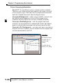
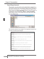
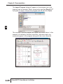
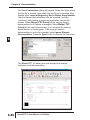
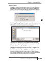
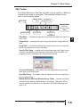
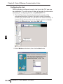
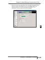
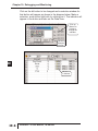
After clicking on the Use Disk button, the programming window will
look a bit different. Notice that the icon buttons in the Online
Toolbar are no longer grayed-out. The indicators at the bottom of
the window tell you that the PLC is okay, the PC is online with the
PLC and the PLC is in Program Mode. At this point the program
has not been written to the PLC. You will also notice the two left
most buttons on the Online toolbar (ReadP and WriteP) are
highlighted. To write the program to the PLC, select WriteP. A pop-up
indicator will appear to let you know that the program is being
written to the PLC.
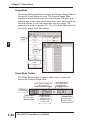
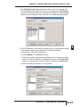
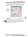
After the program has been written to the PLC, all that needs to be
done is to place the PLC in the RUN Mode. Click on the Mode
button on the Online toolbar. This will bring the PLC Modes dialog
window into view. Click on Run, then OK and the PLC will be in the
RUN Mode.
DirectSOFT 5 User Manual, 1st Edition
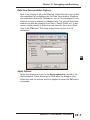
Quick Start
Notice the green indicator at the bottom of the Ladder View. It
shows the PLC is now in the Run Mode. How do you know that your
program works? The best way is to monitor the program while the
PLC is online.
Green indicating
Run Mode
DirectSOFT 5 User Manual, 1st Edition
1
2
3
D
5
6
7
8
9
0
1
2
3
4
A
B
C
D
2-27
Quick Start
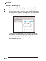
Monitor the Program
1
2
3
D
5
6
7
8
9
1
11
2
13
4
A
B
C
D
2-28
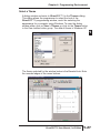
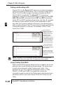
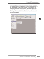
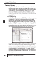
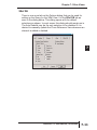
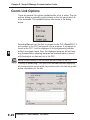
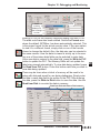
There are many things that can be monitored in the relay ladder
program by simply clicking on the Status button on the online
toolbar. The monitor mode can be turned On and Off by clicking on
the status button. When in the status mode, the element background
will change to blue (by default) to indicate power flow when the input
element is turned on. If there is power flow, the output background
will also change color.
Background color
to indicate power
flow (I/O On).
The program editing and testing is now complete. The example
program is the most simple program that can be written. You can
add to this program by deleting the END rung (Rung 2) and
continuing to edit additional rungs. Do not forget to end your
program with an END rung.
DirectSOFT 5 User Manual, 1st Edition
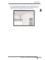
Quick Start
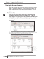
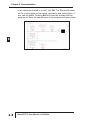
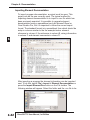
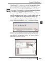
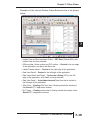
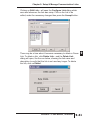
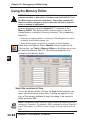
The following picture is an example of how you might continue with
your program. Note the Cross Reference View and the Data View.
Chapters 9 and 10 will explain how to use these views.
1
2
3
D
5
6
7
8
9
0
1
2
3
4
A
B
C
D
DirectSOFT 5 User Manual, 1st Edition
2-29
MANAGING
PROJECTS
CHAPTER
3
In This Chapter
Get Started Using DirectSOFT 5 . . . . . . . . . . . . . . . . .3-2
Create a New Project . . . . . . . . . . . . . . . . . . . . . . . . . .3-4
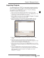
Importing Projects . . . . . . . . . . . . . . . . . . . . . . . . . . . . .3-5
Copy or Save Existing DirectSOFT Files . . . . . . . . . . .3-7
Chapter 3: Managing Projects
Get Started Using DirectSOFT 5
2
3
D
5
6
7
8
9
1
11
2
13
4
A
B
C
D
3-2
To open DirectSOFT 5, double-click on the DirectSOFT 5
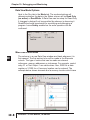
icon which was installed on your desktop screen during
the installation of the software. You can also click on Start
located in the left-hand corner of the computer monitor. Once you do
this, select Programs, find DirectSOFT 5, then select DSLaunch 5
in the drop-down window. The DSLaunch window, shown below, will
appear. The DSLaunch window displays all of the applications and
PLCs that DirectSOFT 5 supports.
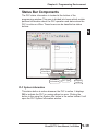
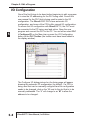
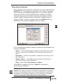
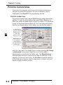
Understanding the Launch Window
DirectSOFT 5 Programming Software is much more than a PLC
programming package. With the Launch Window concept, utilities,
such as, NetEdit, CTRIO WB, etc., can all be launched from one
central location. The Launch Window is also used to create and
manage PLC projects and the communication links between your
personal computer and the PLC.
Notice the different areas in the Launch Window. There is a menu
tree very similar to what is in Windows Explorer. All that you see in
the menu tree can be accessed from the tree.
Windows-type
Menu Tree
Utilities, such
as NetEdit
Installed
Support
Communication
Links to PLCs
DirectSOFT 5 User Manual, 1st Edition
Chapter 3: Managing Projects
The menu tree has four folder/icons which are:
• Applications Ҁ These are the applications currently installed in
DirectSOFT 5. The only installed application available is
DirectSOFT 5 Programming. This is the point where you start a
new project.
• Utilities Ҁ Several utilities are installed here such as, ERM Workbench,
CTRIO Workbench and NetEdit. They are installed automatically when
DirectSOFT 5 is installed.
• Projects Ҁ This folder/icon will contain the projects which are created in
DirectSOFT 5. A project is the collective name for your ladder
logic program and all of the documentation associated with it.
Newly created projects and existing projects will reside here. As
projects are created, they are added to the end of the list.
• Comm Links Ҁ This folder/icon will contain the communication links
between the personal computer and the different PLCs that you have
(See Chapter 9).
DirectSOFT 5 User Manual, 1st Edition
2
3
D
5
6
7
8
9
0
1
2
3
4
A
B
C
D
3-3
Chapter 3: Managing Projects
Create a New Project
New Program
2
3
D
5
6
7
8
9
1
11
2
13
4
A
B
C
D
3-4
To create a new program, double-click on DirectSOFT 5
Programming in the Applications folder on the DSLaunch menu
tree.
Double-click here
to start a new
program
Enter the New Project Information
The New Project dialog box is used to define several things.
• New Project Name Ҁ enter a name for your project (up to 32 characters
- no extension).
• Family Ҁ select the DirectLOGIC PLC family (or compatible) you will be
using.
• Type Ҁ select the CPU you are using from the available list. Remember,
different PLCs use similar instructions, but they are still different in some
ways. For this reason, it is extremely important that you specify the
correct CPU.
• Browse Ҁ you can keep the default project path,
c:\DirectSOFT5\projects, or use the Browse button to either select a
project not shown on the menu tree or a different folder with the project
listed in it.
DirectSOFT 5 User Manual, 1st Edition
Chapter 3: Managing Projects
Importing Projects
You may already have TISOFT or Logicmaster programs stored on
your PC’s hard drive or on a disk. You may also have projects that
were exported from DirectSOFT version 4. Use the following
procedure to import these programs.
1. Open the New Project dialog as described on the previous page.
2. When the New Project dialog appears, click on the Cancel button. The
programming window will remain on the screen.
3. Click on File on the toolbar, then select Import > Program. The Import
Program dialog will appear as shown below.
4 Locate the program to be imported by selecting Look in:, then the
location of the program, such as, on a diskette in the PC’s drive A:.
5. Select the Files of type: to choose the correct file, such as, TIsoft
(*.vpu).
6. Select the program to be imported (up to 32 characters with no
extension) from the diskette or other media where the program is found.
The file name should appear in File name: area.
7. Either enter a name for the project in the New Project: area or use the
Browse button to select the name from a location of your choice to store
the project.
8. Click on the Open button to start the import process. An indicator
window will appear to let you know that the program is being imported.
After the program has been imported, it will appear as a normal
DirectSOFT 5 program.
DirectSOFT 5 User Manual, 1st Edition
2
3
D
5
6
7
8
9
0
1
2
3
4
A
B
C
D
3-5
Chapter 3: Managing Projects
Program Documentation Mapping from TISOFT and
Logicmaster
Although most of the documentation will have a counterpart in
2
3
D
5
6
7
8
9
1
11
2
13
4
A
B
C
D
3-6
DirectSOFT 5 some of the documentation will not. The following table
shows what is imported, what is not and the DirectSOFT 5 counterparts.
TISOFT Source Documentaion
DirectSOFT 5 Documentation
Title Page
Synonyms
Comments (tied to output coil)
Descriptions
Title Page Editor
Element Description
Rung Comments (tied to rung)
No Match
Logicmaster Source Documentaion
DirectSOFT 5 Documentation
Nicknames
Names
Comments
Coil Labels
Nicknames
Description
Comments
No Match
DirectSOFT 5 User Manual, 1st Edition
Chapter 3: Managing Projects
Copy or Save Existing DirectSOFT Files
The question often arises as to what is needed when copying
existing DirectSOFT files to a different memory area or directory
using the DOS command line syntax or any type of file manager. If
you are a first time user of DirectSOFT 5 and have no existing files
to transfer, then you may skip this page and read it later.
By default, projects are stored originally in the Projects
subdirectory, however, they can reside in areas other than the
default projects subdirectory. It really does not matter where they
are storedҀthe method for copying or saving these existing files to
another area is the same in each case.
If you look where the projects have been stored, you will notice the
main file for the project will always have a .prj extension after its
root filename, but there are other files with the same root filename.
This can be a little confusing to new users. This is due to the fact
that DirectSOFT 5 performs a filename creation behind the scenes,
and you don't get involved with the initial storage except to indicate
the root filename and directory path.
A frequently asked question is "which of these files do I need when
making the storage transfer?". Copying or saving the filename.prj
will be insufficient to truly transfer the total project. Not all of the files
are necessary to recreate the program, but if you eliminate any of
them, you may lose some important documentation and indexing
information. The table shown on the following page lists the different
file extensions and what they contain. The safest choice is to save
or copy all files for a project having the same root filename,
regardless of the different file extensions (see the table on the next
page).
DirectSOFT 5 User Manual, 1st Edition
2
3
D
5
6
7
8
9
0
1
2
3
4
A
B
C
D
3-7
Chapter 3: Managing Projects
DirectSOFT 5 Project Files
File Extension
2
3
D
5
6
7
8
9
1
11
2
13
4
A
B
C
D
3-8
dataviewname.dta
filename.dv
filename.esd
filename.esx
filename.inf
filename.lcd
filename.lcx
filename.lda
filename.ldo
filename.pid
filename.prj
filename.prt
filename.rd
filename.rf
filename.scd
filename.scx
filename.tls
filename.vd
filename.vf
filename.wsp
filename.xml
Contents
Data views are not associated with one single
project, but can be shared among multiple projects
DV1000 setup
Element documentation
(nickname, wiring information, description)
Index file for the element documentation
Project information
Ladder rung comments
Index file for the ladder rung comments
Connects rung comments to correct rung no.
Online only: connects to correct rung number
(temporary until saved offline to *.lda
PID documentation
Contains the ladder program
Print settings
305 R-memory data
305 R-memory editor format
Stage comments
Index file for stage comments
PLC parameters, I/O configuration, pause bits
V-memory data
V-memory editor format
Position of program windows, colors, etc.
Docking pane layouts
Files Associated with DirectSOFT 5 Project Files
File Extension
importexport doc.namename.csv
ctrioworkbenchname.cwb
ermworkbenchname.erm
importexportmnemonicname.txt
Contents
Comma Separated Variable
Counter I/O configuration
Ethernet remote master configuration
Text file
DirectSOFT 5 User Manual, 1st Edition
PROGRAMMING
ENVIRONMENT
CHAPTER
4
In This Chapter
Offline Toolbar Components . . . . . . . . . . . . . . . . . . . . .4-2
Online Toolbar Components . . . . . . . . . . . . . . . . . . . . .4-5
Additional Toolbars . . . . . . . . . . . . . . . . . . . . . . . . . . . .4-6
The Options Dialog . . . . . . . . . . . . . . . . . . . . . . . . . . .4-21
Colors in DirectSOFT 5 . . . . . . . . . . . . . . . . . . . . . . .4-24
The Split Screen Feature . . . . . . . . . . . . . . . . . . . . . .4-30
The New Window Feature . . . . . . . . . . . . . . . . . . . . . .4-31
Chapter 4: Programming Environment
Offline Toolbar Components
1
2
3
4
5
6
7
8
9
1
11
2
13
4
A
B
C
D
4-2
Once the Program Window has been opened, the Online and Offline
toolbars are in view. The diagram below shows the default location
of the Online and Offline Toolbars whenever a new program is
started. The grayed-out icon buttons become highlighted as the
program is being edited. Along with the toolbar icon buttons, the
button functions are also available from the menu bar located at the
top of the program window. The grayed-out Online toolbar will
become available once the PC is online with the PLC. The toolbars
Menu bar
Offline Toolbar
Online Toolbar
are movable, or floating. By selecting the toolbar and dragging it
with the mouse, the toolbar can be located wherever the
programmer wishes to place it on the desktop.
Offline Toolbar
Read from Disk
This button is used to retrieve and open a project from a disk, (i.e.
HD or floppy). The program will appear in the Ladder View.
Write to Disk
The ladder logic program will be saved to the .prj project file on disk
(not the entire project). It is a good practice to save your work
frequently. This helps prevent data losses in the event of a system
problem, such as a power failure.
New Program
This button will begin a new program offline. This button can be
used with a project already open. The project will not be overwritten
with the new project. You will be prompted to save the project before
a new Ladder View will appear.
Open a Project
This will open an existing project. A project can be open when an
existing project is already open. You will first be prompted to save
your project, then the project that has been selected will be opened.
DirectSOFT 5 User Manual, 1st Edition
Chapter 4: Programming Environment
Backup to File
Click on this button to make a backup copy of your project.
1
Edit a Program
This button will turn on the Edit Mode. When the ladder view is in
Edit Mode, the edit cursor will be a solid block on the screen. Click
the Edit Mode button again to toggle back to Display Mode.
Accept the Program
Before the edited program can be downloaded to the PLC, the
Accept button must be pressed. Once this is done, the program will
be compiled; in other words, the program is put into a form that can
be downloaded to the PLC.
Cut
This button is available in the Edit Mode. It allows the programmer
to delete a marked, or selected, rung from the program and place it
on the clipboard.
Copy
This button allows the programmer to copy one or more marked, or
selected, program rungs to the clipboard (see page 5-21).
Paste
Whenever rungs are cut or copied, they are stored on a clipboard.
Position the cursor where you want the rungs to go, then use this
button to paste the rungs currently on the clipboard to the new
location.
Find
This button is used to locate an element within a program. The
element can be selected with the cursor before using the button or
click on the button and enter the element to be found.
Next
Using this button will find the next occurrence of the element
specified when the Find button has been used.
Browse for an Element
This button provides a quick overview of valid element ranges and
nicknames for the current content as well as a convenient way to
document an element.
DirectSOFT 5 User Manual, 1st Edition
2
3
4
5
6
7
8
9
0
1
2
3
4
A
B
C
D
4-3
Chapter 4: Programming Environment
1
2
3
4
5
6
7
8
9
1
11
2
13
4
A
B
C
D
4-4
Display the Options Dialog
Using this button will display the Options Dialog which will allow the
programmer to set up the different dialog views available to the
programmer.
Zoom
These buttons are used to either increase or decrease the size of
the Ladder View. The (+) button increases the size of the view. The
Out (-) button decreases the size of the view.
Help
This button will open the Help menu window.
DirectSOFT 5 User Manual, 1st Edition
Chapter 4: Programming Environment
Online Toolbar Components
The following button icons are available after the PLC is placed on
line.
Online Toolbar
Read the Program From PLC
This button will read the program from the online PLC.
Write the Program to PLC
This button will write the program to the online PLC.
Program Status
This button will turn on the status display for the current ladder logic
view.
New Data View
Using this button will open a Data View window (see Chapter 10).
Change Value
This button will open the Change Value window to allow the
programmer to change element status, values, etc..
PLC Mode
This button opens the Mode window to display the current mode of
the PLC and to allow the Mode of the PLC to be changed. Choices
are Run, Program and Test.
System Information
Use this button to open a window with the version, status and error
information about the PLC.
Syntax
This button will run a Syntax check of the PLC and a Duplicate I/O
check.
1
2
3
4
5
6
7
8
9
0
1
2
3
4
A
B
C
D
Toolbar Options
This arrow will allow the programmer to add or delete buttons from
the toobar, also will view additional buttons that would not fit on the
display screen.
DirectSOFT 5 User Manual, 1st Edition
4-5
Chapter 4: Programming Environment
Additional Toolbars
1
2
3
4
5
6
7
8
9
1
11
2
13
4
A
B
C
D
In addition to the default Offline and Online toolbars, other toolbars
can be activated and used if desired. To view additional toolbars
click on View > Toolbars and select the toolbar or toolbars that
would assist you with editing your program. The Toolbar selection
window lists fourteen toolbars and a Customize option. The three
toolbars at the top of the list are checked since they are the default
toolbars. The rest of the toolbars are optional, and they can be
selected if desired. Note the down arrow at the end of each toolbar.
This down arrow allows the programmer to customize the toolbar by
adding or removing buttons.
After selecting the file toolbar, it will be added to the Ladder View
window beneath the Online toolbar as shown in the diagram below.
This toolbar can be moved to any location of the programmer’s
preference by dragging it with the mouse arrow.
Added Toolbar
4-6
DirectSOFT 5 User Manual, 1st Edition
Chapter 4: Programming Environment
The File Toolbar
The File Toolbar duplicates the more commonly used commands
from the main menu File. Notice that the icon buttons are in groups,
divided by a gray vertical line.
1
2
3
4
New Online Project
5
Create a new project that linked to the PLC.
6
Close Project
This button will close the current project. A message window will
7
pop-up if the program has not been saved. The program can then
be saved.
8
Save Project to Disk
This button will save the entire project to disk, and will also create a 9
new auto-backup version of the project.
0
Save Project to PLC
Use this button to save the entire project to the PLC.
1
Save As to Disk
Use this button to save the active project to a different disk file.
2
Import
This button will allow the programmer to import a project from a non- 3
DirectSOFT5 format.
4
Import Element Document
This button allows the programmer to import a document containing A
nicknames, wiring information and descriptions from comma
separated variable (.csv) text format.
B
Import Rung Comments
C
This button will allow the importation rung comments in text form
from a ladder logic program.
D
Export
This button is used to export a project to a non-DirectSOFT5 format
(see Chapter 6).
DirectSOFT 5 User Manual, 1st Edition
4-7
Chapter 4: Programming Environment
1
2
3
4
5
6
7
8
9
1
11
2
13
4
A
B
C
D
4-8
Export Element Comments
This button allows the programmer to export element documentation
containing nicknames, wiring information and descriptions in the
current DirectSOFT 5 project to a text file in comma separated
variable text format.
Export Rung Comments
This button will allow the programmer to export the active ladder
logic rung comments in text form.
Preview the Program
Use this button to display the current view as it would appear in
printed format. Once previewed, the program can be printed.
Print
This will allow the printing of the current view and selected
documents.
Print All
Use this button to allow the programmer to print all of the
documents that are selected.
Setup
This button will open the printer setup dialog.
Property
This button will show the project properties.
Exit
This button will allow the programmer to exit the project. If the
project has not been saved, a pop-up window will remind the
programmer to save the project, otherwise, the project will close.
The Edit Toolbar
The Edit Toolbar is only active in the Edit Mode. It duplicates some
of the main menu Edit commands.
Undo
Use this button to undo the changes to the current rung that has
been edited and not yet compiled. The edit cursor must be on the
rung to be restored when the undo button is clicked on.
DirectSOFT 5 User Manual, 1st Edition
Chapter 4: Programming Environment
Delete
The Delete button will delete the element under the edit cursor. If
there is no element under the cursor to be deleted, a pop-up
message asks if the rung is to be deleted. If multible rungs are
selected (highlighted), it will delete these rungs (SeeChapter 5).
1
Insert
This button will allow rows and columns to be inserted in a rung.
Merge the Previous Rung
This button will merge the previous rung with the current rung.
Merge the Next Rung
Use this button to merge the next rung with the current rung.
Browse Contact
This button will open the Instruction Browser window ready for a
contact to be selected.
Browse Coil
This button opens the Instruction Browser window ready for the
selection of a coil.
Browse Boxes
Use this button to open the Instruction Browser with the box
instructions available for selection.
The Search Toolbar
The Search Toolbar only contains two command buttons, Replace
and GoTo.
Replace
This button will activate the replace dialog so the programmer can
search for an object in the program, or a range of elements and
replace them.
GoTo
This button activates a Goto dialog so the programmer can enter a
rung number or addresss he wishes to view. Pressing OK will
display the cursor on the desired rung/address.
DirectSOFT 5 User Manual, 1st Edition
2
3
4
5
6
7
8
9
0
1
2
3
4
A
B
C
D
4-9
Chapter 4: Programming Environment
The View Toolbar
1
2
3
4
5
6
7
8
9
1
11
2
13
4
A
B
C
D
4-10
The View Toolbar has three buttons, two of which are from View on
the Menu bar.
Customize
This button allows the programmer to display or hide the various
Toolbars, to modify the commands that appear on each Toolbar, or
to create you own Custom Toolbars.
Theme
Use this button to select from a variety of User Interface Themes
that will give DirectSOFT 5 a new look and feel. You can chose
themes, such as, the Office XP theme, the Office 2003 theme, the
Mac theme, et al.
Color
Use this button to activate a Color Setup dialog so the programmer
can select different colors for various items in DirectSOFT 5, such
as, the background for the Ladder View.
DirectSOFT 5 User Manual, 1st Edition
Chapter 4: Programming Environment
The Tools Toolbar
The Tool toolbar duplicates the Tools menu from the main menu.
These buttons can be a valuable asset to the programmer.
1
Memory Editor
This button will open the Memory Editor dialog which will allow the
programmer to edit data in V-memory.
Documentation Editor
This button opens the Documentation Editor view to be used to
define Nicknames, Wiring Information and Descriptions for the
elements which are used in the program.
Assign Nickname
DirectSOFT 5 allows the programmer to create an entire program
with Nicknames without first assigning them to the actual elements
(a.k.a. Symbolic Programming). When the program is ready to be
written to the PLC, pressing the Nickname button opens the Assign
Nicknames dialog where the programmer can assign actual
elements to the unassigned Nicknames used in the program,
Comment
This button activates the Edit Comments dialog where the
programmer can create or modify the comment for the current rung
in the Ladder View, or the current stage in the Stage View.
Title
Use this button to allow the programmer to Edit the title for the
project.
Compare
This button provides a window so the programmer can compare the
current program with another program on disk or with the program in
the PLC.
Insert Instructions
This button is used to insert instructins from a Mnemonic text file
into the current program, optionally including element
documentation.
DirectSOFT 5 User Manual, 1st Edition
2
3
4
5
6
7
8
9
0
1
2
3
4
A
B
C
D
4-11
Chapter 4: Programming Environment
The PLC Toolbar
1
2
3
4
5
6
7
8
9
1
11
2
13
4
A
B
C
D
The PLC toolbar duplicates the some of the features found on the
PLC menu menu bar.
Connect to PLC
This button will allow the programmer to connect the PC to the PLC
over a communication link. If a link has not been established, one
can be setup here.
Disconnect from PLC
Use this button to disconnect the PC from the PLC.
Link
This button will open the Link Info dialog which will provide a quick
overview of the current link's status and allows the programmer to
edit and set the activation state of the link.
Setup (PLC)
This button allows the configuration of the PLC type while offline.
Display Memory Map
Use this button to open the current PLC Memory Map.
List Configuration Tools
This button will open the Hardware Tools list. The programmer can
select a software tool to run from this list as long as it has been
installed.
I/O Configuration
This button will open the Configure I/O window that displays the
current configuration of the installed PLC I/O (Chapter 5).
Setup a Password
This button will allow the programmer to set a password in the PLC
to protect the program from unauthorized access.
Clear Memory
This button is for clearing the memory in the PLC.
PLC to Disk
This button will allow the programmer to copy the I/O configuration
from the PLC to disk.
4-12
DirectSOFT 5 User Manual, 1st Edition
Chapter 4: Programming Environment
Disk to PLC
This button will allow the copying of the configuration data from the
disk to the PLC.
The PLC Diagnostics Toolbar
The buttons on the Diagnostics Toolbar will only be active when the
PC is online with the PLC.
PLC Diagnostics
Pressing this button will perform diagnostics on the connected PLC.
Observe the Scan Time
Press this button opens the Scan Time dialog which allows the
viewing of the current, minimum and maximum scan times from the
current PLC. The scan times are continuously updated while the
dialog is visible.
View Error Messages
The messages button will open a window that displays System
Errors and Fault Messages which have occurred.
The PLC Setup Toolbar
Some of the buttons on the PLC Setup Toolbar can be used offline,
but all of the buttons can be used with the PLC online.
Set the Pause Bits
Use this button to open the Pause Bit editor which allows the
programmer to set output pause bits.
Setup Overrides
This button will open the PLC Override editor.
1
2
3
4
5
6
7
8
9
0
1
2
3
4
A
B
C
D
Name the Memory Cartridge
This will open the Memory Cartridge dialog used to set a name in
the current memory cartridge in the PLC.
DirectSOFT 5 User Manual, 1st Edition
4-13
Chapter 4: Programming Environment
The PLC Setup Toolbar (cont’d)
1
2
3
4
5
6
7
8
9
1
11
2
13
4
A
B
C
D
4-14
Set the Retentive Memory Range
This button will open a Retentive Range dialog to configure the
retentive memory for the current PLC.
Set the Watch Dog Timer
Pressing this button will allow the programmer to view/edit the watch
dog time-out value for the current PLC.
Initialize Scratch Pad
Pressing this button will begin the process of Initializing the Scratch
Pad Memory.
Select I/O
This button is used to determine which I/O Config will be read from
the PLC on power up.
I/O Check
This button is used to turn on or off the I/O Config check when the
PLC powers up.
D0-DCM Port Setup
This button is used to setup the D0-DCM communication ports.
Secondary Port Setup
Press this button to setup the PLC Secondary Communication Ports.
Setup Global I/O
This button is used to setup the global I/O for the DL405 PLC only.
Set the Time and Date
Press the Calendar button to set the time and date in the PLC.
Set up the DV-1000
If there is a DV-1000 installed with the PLC, use this to open the DV1000 setup dialog (refer to the DV-1000 User Manual for setup
instructions).
Setup the PID Loops
The PID button will allow the programmer to setup the PID loop
parameters.
Select a Memory Cartridge
This button will allow the programmer to select the memory type for
a DL405 PLC.
DirectSOFT 5 User Manual, 1st Edition
Chapter 4: Programming Environment
Setup Intelligent I/O
Press this button to open the Intelligent I/O setup dialog to set up
intelligent modules. The list contains configuration script for all
intelligent modules in the current PLC.
The Debug Toolbar
The Debug Toolbar extends the use of the Status button located on
the Online toolbar. These buttons will assist in the debugging of
your program.
Turn Status ON in All Views
The AllStat button will turn on the status for all of the open views in
the current project.
Turn Status OFF in All Views
The NoStat button will turn off the status for all of the open views in
the current project.
Open Data View
This button will allow the programmer to open an existing Data
View.
Close Data View
This button will allow the programmer to close the current Data
View.
Save Data View
This button will save the current Data View.
Data View Save As
This button will allow the programmer to save the current Data View
with a new name.
Test Mode
This button will allow the programmer to use the Test Mode
Operations (see page 10-22).
Stack Operations (DL440 only)
Use this button to monitor the DL440 PLC accumulator and data
stack.
DirectSOFT 5 User Manual, 1st Edition
1
2
3
4
5
6
7
8
9
0
1
2
3
4
A
B
C
D
4-15
Chapter 4: Programming Environment
1
2
3
4
5
6
7
8
9
1
11
2
13
4
A
B
C
D
Trap Monitor
This button will open a dialog which allows the programmer to trap
element values at specific addresses rather than after a scan (see
page 10-25).
The Window Toolbar
The Window Toolbar duplicates the window option from the main
menu. This toolbar may be helpful if the window views need to be
changed often.
New Window
This button will add a new Ladder View of the current Ladder View.
Arrange View Cascaded
The Cascade button will rearrange views in a cascaded fashion.
Tile Views Horizontally
This button will arrange the Ladder/Stage Views in a tiled, horizontal
fashion.
Tile Views Vertically
This button will arrange the Ladder/Stage Views in a tiled, vertical
fashion.
Arrange Icons
Use this button to arrange the icons for minimized windows at the
bottom of the main window. If there is an open document window at
the bottom of the main window, then some or all of the icons may
not be visible because they will be underneath this document
window.
Default
Pressing this button will restore window and toolbar positions to their
factory default layout settings.
Close All Views
This button will close all current views.
Output Window
This button will display the Output Window.
Clear Output Window
This button will clear all messages in the Output Window.
4-16
DirectSOFT 5 User Manual, 1st Edition
Chapter 4: Programming Environment
The Help Toolbar
The Help Toolbar duplicates the Help menu accessed from the main
menu.
Help Topic Index
Use this button to open the Help window.
PLC/Instruction Matrix
This button will open the PLC vs. Instruction Set Matrix window.
Getting Started
The Start button will open the Help window to provide help to get
started using DirectSOFT 5.
Tip of Day
This button will open the Tip of the Day window to provide a helpful
tip.
Unlock
This button will convert DirectSOFT100 to full version using
Purchased Product Keycode.
About
This button will display the DirectSOFT 5 about box.
The Custom Toolbar
DirectSOFT 5 has many toolbars to select, and if you select too
many, you probably won’t have much room on the monitor to
effectively edit a program. The customize toolbar feature may be
well suited for your use. Click on Customize at the bottom of the
Toolbars menu to open the Customize toolbar window shown below.
DirectSOFT 5 User Manual, 1st Edition
1
2
3
4
5
6
7
8
9
0
1
2
3
4
A
B
C
D
4-17
Chapter 4: Programming Environment
1
2
3
4
5
6
7
8
9
1
11
2
13
4
A
B
C
D
TIP: A quick way to open the Customize Toolbar dialog is to right-click on
any of the Toolbars in view. This will access the Toolbars menu, then select
‘Customize...
The Customize window will allow the programmer to select all the
toolbars he wishes to use, or to customize a personal toolbar. When
a toolbar is checked (clicked on) it will be added to the programming
window immediately. To create your personal toolbar click on New
and name the toolbar. “My toolbar” is the name given to a custom
toolbar in the diagram below. The toolbar will be added to the
programming window as an add-on toolbar. The toolbar will not
have any icon buttons in it until the programmer selects the buttons.
To do this, click on the Commands tab and select the command
category. Once this is done, a list of icon buttons will appear to the
right of the category list. Drag the commands that you wish to the
personal toolbar. The name of the personal toolbar will also be
added to the list of Toolbar menus.
Personal Toolbar
4-18
DirectSOFT 5 User Manual, 1st Edition
Chapter 4: Programming Environment
Status Bar Components
The PLC status information is located at the bottom of the
programming window. This area is divided into boxes which contain
pertinent information about the PLC operation and status when the
PLC is online or offline. These boxes can be classified as status
buttons.
1
2
3
4
5
6
7
8
9
0
1
2
3
4
PLC System Information
A
This status button is active whenever the PLC is online. It displays
B
OK to indicate the PLC is running without an error. Clicking the
button is like using the System Info button in the online toolbar. It will
C
open the PLC System Information window.
D
PLC System
Information
PLC Mode
Link
Information
Program
Memory Usage
PLC Type
Program
Location
DirectSOFT 5 User Manual, 1st Edition
4-19
Chapter 4: Programming Environment
Communication/Link Information
1
2
3
4
5
6
7
8
9
1
11
2
13
4
A
B
C
D
4-20
This status button is active when the PLC is offline or online. The
button displays the PLC status and the communication link name.
Clicking this button will open the Communication/Link Information
window. The window will show the communication error messages.
It is also possible to edit the communication link if it becomes
neccesary. If the PLC is offline, it will indicate that here. Clicking on
the button with offline showing will allow the programmer to connect
the PLC to the PC.
PLC Mode
This status button indicates the operational mode of the PLC. Not
only does this button indicate the PLC Mode but it also allows the
programmer to use this button like the Mode button in the online
toolbar. Clicking on this button will allow the person to change the
mode of the PLC.
Program Memory Usage
This box indicates the amount of relay ladder program memory that
is available and how much has been used. The format is: memory
used/total memory available. If the available memory is exceeded,
an asterisk (*) will appear beside the amount used. Here are some
examples:
• For a DL06 CPU with program memory of 00003/07680 indicates that 3
words have been used out of a total of 07680.
• For a DL230 CPU indicating the program memory with *00725/00512.
This means that the amount of words used has exceeded the total
program memory available (see the diagram on the previous page).
PLC Type
This box indicates the type of PLC that is being used.
Program Location
This box indicates the position of the program cursor in the Ladder
View. This indicator changes with each movement of the cursor.
DirectSOFT 5 User Manual, 1st Edition
Chapter 4: Programming Environment
The Options Dialog
Before continuing to edit your program, it is a good idea to get
familiar with the DirectSOFT 5 Options Dialog. This dialog actually
has six dialogs within which are used to setup the appearance of
each of the views available. To open the dialog, either click on the
Options button or on View > Options. Each view dialog is indicated
by a tab labeled:
• Data View - used to monitor and debug the program
• Global - this affects all views (display of aliases or nicknames)
• Ladder - options for the ladder view
• Stage - options used for the stage view
• XRef - used to setup the cross reference view (display mode,
documentation, etc.)
• XRef DB _ definitions for cross reference database queries
Only the Global and Ladder options will be discussed in this chapter.
The other option tabs will be discussed in later chapters after
adequate coverage of some of the more advanced features of
DirectSOFT 5.
DirectSOFT 5 User Manual, 1st Edition
1
2
3
4
5
6
7
8
9
0
1
2
3
4
A
B
C
D
4-21
Chapter 4: Programming Environment
Ladder Options
1
2
3
4
5
6
7
8
9
1
11
2
13
4
A
B
C
D
4-22
Number Rungs
Two choices are available here, by Address and by Rung. If by
Address is chosen, the actual decimal address for each rung will be
in located in the left margin of the ladder view, starting with zero. If
number by Rung is chosen, the rungs will be numbered beginning
with the number one. The following rungs will be numbered
sequentially, two, three, four, etc. The default selection is by Rung.
Documentation
This section of the dialog allows you to select the types of
documentation that will appear in the Ladder Logic program. A
check mark in the box preceding the option will select the option to
appear in the program. The following choices are available:
• Elements - the element type and reference number (X1, Y3, C10, etc.)
• Nicknames - a name given to the element by the programmer or user
(clamp, switch, etc.)
• Wiring Info - a descriptive tag for keeping track of wiring (Blue 027)
• Descriptions - notes attached to individual elements (gate open, clamp
up)
• Comments - note attached to the rung, i.e. This is the start of the
Wash Process for Section 9 in Building 10
Misc. Options
The only option availble here is 3-D Tokens. Leaving this option
checked will leave the Ladder View the way it appears when it is
first opened (default), that is, with a three dimensional effect on the
Ladder View. When this option is unchecked, the Ladder View will
have a white background and black rungs. This will not affect the
colors of the displayed views.
Apply the Options to:
By default, the changed options will only affect the Current View.
Check All Open Views or New Views if the changes are to affect
other opened views or views to be opened later.
DirectSOFT 5 User Manual, 1st Edition
Chapter 4: Programming Environment
Global Options
The options available with the Global tab affect the current and all
new projects that are opened during any session.
1
Selecting the Global Options
2
3
4
5
6
7
8
9
0
1
2
3
4
A
B
C
D
• Default View - the view that is highlighted in the Default View window
when the OK button is selected will be the default view that appears
whenever a project is opened.
• Display Aliases - Aliases are alternate names given to certain elements
or addresses. For example, TA0 is an alias for a timer accumulator data
starting at V0. It is much more meaningful to use the aliases rather than
the counterpart memory address notations. But in the end, it is a matter
of preference. The aliases can be turned ON or OFF globally. See the
PLC User Manual for a complete list of aliases for the CPU being used.
• Display Nicknames - when this is selected, all current or future projects
opened will display the nicknames. Selecting Display Nicknames here
will have precedence over how this option is set for the individual views
in the other options.
DirectSOFT 5 User Manual, 1st Edition
4-23
Chapter 4: Programming Environment
Colors in DirectSOFT 5
1
2
3
4
5
6
7
8
9
1
11
2
13
4
A
B
C
D
4-24
Colors are used in DirectSOFT 5 for personal appearance and for
certain information. This will be a discussion of how and where
colors are used.
Select New Colors
The programmer can setup the colors that he prefers for the
projects to be developed. The selected colors will remain the same
for each project. To open the Color Setup window, click on View >
Color Setup or click on the Color button in the View toolbar button
group. The Color Setup will appear like the dialog below. The colors
are changed by selecting the usage (Normal Background,
Comment, etc.) under Selection then click on the color in the
Colors palette. The Sample area (below the Color palette) has a
color bar that will change as the colors are selected. Rows of text
will also change color for each type of documentation selected.
These are the rows of Cs, Ds, Ws, etc.
Click on the
desired color
Click on item
to select for a
color change
Letters match
documentation
selections
Vertical bars
match
highlighting for
selected rungs,
uncompiled, etc.
DirectSOFT 5 User Manual, 1st Edition
Chapter 4: Programming Environment
Color Selections
Normal Background 앥 the normal background color (the default is
white with 3-D Token disabled)
Selected Background 앥 used for setting the color that appears
when something in the program is selected. For example, if a range
of rungs is selected (to copy, delete, etc.) the selection is highlighted
with a color (default is blue)
Status Background 앥 when online status is selected, this
background color shows that the element is enabled (default is
aqua)
Status Foreground 앥 the color the individual element addresses
show when they are active during status
Comments 앥 the color used for the rung comments
Description 앥 the color used for the element description
Wiring Information 앥 the color used to indicate the wiring
information
Nickname 앥 the color used to indicate the nicknames
Element 앥 the color used for the element address (X10, IO000,
etc.)
Token 앥 the color used for the ladder program
The Default Settings
If the colors become totally disorganized, click on the Defaults
button to restore the colors to the DirectSOFT 5 default settings.
Monochrome
Selecting the Monochrome button will set all colors to black with a
white background.
DirectSOFT 5 User Manual, 1st Edition
1
2
3
4
5
6
7
8
9
0
1
2
3
4
A
B
C
D
4-25
Chapter 4: Programming Environment
Colors Conveying Information
1
2
3
4
5
6
7
8
9
1
11
2
13
4
A
B
C
D
4-26
DirectSOFT 5 uses different colors to indicate certain conditions.
There are color coded vertical bars located in the margin to the left
of the program rungs. These bars lets the programmer know what
has been compiled and saved. See the diagram below.
Uncompiled Background 앥 when a rung is edited, a vertical color
bar (default yellow) appears to the left of the program as an
indication that the program has not been compiled (accepted).
Unsaved to Disk Background 앥 after the program has been
compiled, the uncompiled bar is replaced with another bar (default
green) to indicate that the program has not been saved the disk.
Unsaved to PLC Background 앥 one other color bar is used after a
program has been compiled, this bar indicates that the program has
not been downloaded to the PLC.
Color Bars
Uncompiled (Yellow)
Compiled, but not
written to disk
(Green)
Compiled, but not
written to PLC (Blue)
DirectSOFT 5 User Manual, 1st Edition
Chapter 4: Programming Environment
Select a Theme
A dialog window exclusive to DirectSOFT 5 is the Themes dialog.
This dialog allows the programmer to select the look of the
DirectSOFT 5 programming window, much like selecting the
appearance for a computer using Windows. To open the dialog
window either click on View > Themes or click on the Theme button
in the View toolbar button group. The default theme is Windows XP.
The theme selected for the window below is the Beveled look. Note
the rounded edges of the menu buttons.
DirectSOFT 5 User Manual, 1st Edition
1
2
3
4
5
6
7
8
9
0
1
2
3
4
A
B
C
D
4-27
Chapter 4: Programming Environment
The Tool Palette
1
2
3
4
5
6
7
8
9
1
11
2
13
4
A
B
C
D
An important part of the programming environment is the Ladder
Palette. The Ladder palette is visible whenever the programming
window is opened. The element symbols are grayed-out and
inactive when the not in the Edit Mode. Turning on the Edit Mode
activates the Ladder palette and the tool symbols are no longer
grayed-out. When a new project is started, the Ladder palette is
located on the right side of the programming window by default,
however, the palette floats. It can be moved to any position on the
monitor viewing area. Simply “grab” the palette with the mouse
arrow on the bar at the top of the palette and move it to wherever it
may work best for the programmer. The palette can also be resized
similar to the one shown on the facing page.
Ladder Palette
Be Familiar with the Ladder Palette
The Ladder palette is very helpful when first learning to use
DirectSOFT 5. The hot keys can be learned while using the Ladder
palette. The hot keys are labeled on the element keys. Using the hot
keys may be quicker for many programmers. The hot keys appear in
the “Tool Tip” whenever the cursor is over the element button.
NOTE: The Ladder palette which appears on your computer screen may be
different than what is shown in this manual. The tools that appear are
dependent upon the type of CPU being used.
4-28
DirectSOFT 5 User Manual, 1st Edition
Chapter 4: Programming Environment
The Ladder palette shown below will be used to describe each
button.
1
Edit Mode 앥 turn Edit Mode
ON or OFF
Accept 앥 compiles the program
Normally Open Contact
Normally Closed Contact
Normally Open Immediate
Contact
Normally Closed Immediate Contact
Positive Differential Contact
Negative Differential Contact
Equal to Contact
Not Equal to Contact
Equal to or Greater Than
Contact
Less Than Contact
Browse Contacts
Browse Coils
Browse Boxes
Browse Elements
Wire to Output
Wrap Wire to Stage
The contact buttons are self-explained. Each contact button will
place the particular element on the rung wherever the edit cursor is
placed.
Browse Contacts 앥 click on this button to view the Contact dialog
of the Instruction Browser to select a contact of your choice.
Browse Coils 앥 click on this button to view the Coil dialog of the
Instruction Browser to select a coil of your choice.
Browse Boxes 앥 click on this button to view the Box dialog of the
Instruction Browser to select an Instruction Box of your choice.
Browse Elements 앥 click on this button to view the Element
Browser which will allow you to select from various types of memory
addresses (X0, Y0, V2000, etc.). This can be used to edit
Nicknames, Wiring info or Descriptions of Elements.
Wire to Output 앥 clicking this button will turn the horizontal wire
between the last contact to the output ON and OFF.
Wire to Stage 앥 click on this button to draw a powerflow transition
between a contact and a Stage box instruction.
DirectSOFT 5 User Manual, 1st Edition
2
3
4
5
6
7
8
9
0
1
2
3
4
A
B
C
D
4-29
Chapter 4: Programming Environment
The Split Screen Feature
1
2
3
4
5
6
7
8
9
1
11
2
13
4
A
B
C
D
4-30
There may be times when more than one part of the same program
needs to be viewed. DirectSOFT 5 has a split screen feature that
allows the programmer to split the program, horizontally, into two
panes.
Split Screen Bar
To use the split screen feature, there is a bar, Split Screen bar,
located in the right-hand corner of the Ladder View. To split the
screen, position the cursor over the Split Screen bar, then press and
hold the left mouse button. When a parallel bar appears, move it
down to bring the split screen into view and size the screen to your
convenience.
The diagram below illustrates the split screen. Notice that the lower
pane is showing a different rung than the upper pane.
Different
parts of the
program can
be viewed
DirectSOFT 5 User Manual, 1st Edition
Chapter 4: Programming Environment
The New Window Feature
Another handy feature of DirectSOFT 5 is the New Window feature.
This feature is used to open two or more Ladder Views of the same
program. Having two or more views open at once can be helpful
when programming a lengthy program or to view two different parts
of a program simultaneously. To open a new window, click on
Window > New Window. You will know that there are two windows
open by observing the two Ladder View tabs. To place the two
views side by side, click on Window > Tile Vertically. The two
views will be displayed like shown in the diagram below. If the
Window toolbar group is shown on the programming window, simply
click on the NewWn button then the TileVrt button. If desired, the
two views can also be arranged tiled horizontally. Notice that the
split screen feature has been used in the diagram below. Ladder
View 1 has the split screen.
Split Screen
DirectSOFT 5 User Manual, 1st Edition
1
2
3
4
5
6
7
8
9
0
1
2
3
4
A
B
C
D
4-31
EDIT A PROGRAM
CHAPTER
5
In This Chapter
I/O Configuration . . . . . . . . . . . . . . . . . . . . . . . . . . . . . .5-2
Referencing Program Elements . . . . . . . . . . . . . . . . . .5-4
Entering Program Instructions . . . . . . . . . . . . . . . . . . . .5-6
Shortcuts for Entering Instructions . . . . . . . . . . . . . . .5-11
Drawing/Deleting Connecting Lines . . . . . . . . . . . . . .5-19
Selecting Rungs for Deleting, Cutting or Copying . . .5-21
Deleting Rungs . . . . . . . . . . . . . . . . . . . . . . . . . . . . . .5-22
Copying Rungs . . . . . . . . . . . . . . . . . . . . . . . . . . . . . .5-23
Cut and Paste Rungs . . . . . . . . . . . . . . . . . . . . . . . . .5-25
Merge (Combine) Rungs . . . . . . . . . . . . . . . . . . . . . . .5-26
Inserting Columns, Rows and Rungs . . . . . . . . . . . . .5-27
Using Search and Replace . . . . . . . . . . . . . . . . . . . . .5-29
Common Mistakes . . . . . . . . . . . . . . . . . . . . . . . . . . . .5-31
Chapter 5: Edit a Program
I/O Configuration
1
2
3
D
5
6
7
8
9
1
11
2
13
4
A
B
C
D
5-2
One of the first things to be done before beginning to edit a program
is to view the I/O addressing for the PLC being used. Consult the
user manual for the PLC that is being used to assist in the I/O
configuration. The DirectLOGIC PLCs have automatic I/O
configuration, and some of the CPUs offer manual I/O configuration.
To access the I/O configuration with DirectSOFT 5, the PLC must
be connected to the PC being used and online. Open the new
program and connect the PLC to the PC. You can either select PLC
> Configure I/O on the Menu bar or press the I/O Configuration
button on the PLC Toolbar (the toolbar must have been added to
the display window).
The Configure I/O dialog pictured on the facing page will appear
showing the automatic I/O configuration (by default). If a CPU is
being used that can be manually configured and the configuration
needs to be changed, click on the “A” next to the slot that is to be
manually addressed. The “A” will change to an “M” to allow the
address to be changed.
DirectSOFT 5 User Manual, 1st Edition
Chapter 5: Edit a Program
Read from disk
Save to disk
1
Save to PLC
Select
manual
configuration
Read from PLC
After the manual configuration has been set, save the configuration
to the PLC and to the disk. The disk and PLC icon buttons located
in the right-hand corner of the dialog allows the configuration to be
either saved or read.
WARNING: The majority of DirectLOGIC PLCs only require automatic
configuration. Do not use manual configuration unless it is absolutely
necessary.
DirectSOFT 5 User Manual, 1st Edition
2
3
D
5
6
7
8
9
0
1
2
3
4
A
B
C
D
5-3
Chapter 5: Edit a Program
Referencing Program Elements
Data Types
2
3
5
6
7
8
9
1
11
2
13
4
A
B
C
D
5-4
It’s good to know the various ways to refer to the different types of
elements in the PLC. If you have used the DirectLOGIC compatible
products, such as the TI305 , TI405 , or SIMATIC® TI versions, you
are probably familiar with the way elements are represented. The
following table provides a complete list of the various data types and
their meanings.
TM
Type of Data
TM
DL305C
DL05/DL06/DL105
(DL330/DL340 CPU) DL205/DL350/DL405
Input Points
IO
Output Points
IO
Control Relays
C
Stages
S
Timers
T
Timer current
TCA
Counters
CT
Counters current
TCA
Remote I/O Points
IO
Data Registers
R
Pointers (to another V location)
N/A
Special Relays
Uses special C locations
Input Points as Registers
RIO
Output Points as Registers
RIO
Control Relays as Registers
RC
Timer Status Bits as Registers
N/A
Counter Status Bits as Registers
N/A
Remote I/O as Registers
RIO
Special Relays as Registers
RIO
Timer current Values as Pointers
N/A
(to another V location)
Counter current Values as
Pointers (to another V location)
Constants
Octal Constants
Bit of Word
Pointer to Bit of Word
X
Y
C
S
T
TA
CT
CTA
GX/GY
V
P
SP
VX
VY
VC
VT
VCT
VGX/VGY
VSP
PTA
N/A
PCTA
K
N/A
N/A
N/A
K
O
B
PB
DirectSOFT 5 User Manual, 1st Edition
Chapter 5: Edit a Program
Aliases
Chapter 4 briefly mentioned the use of aliases to make some data
references easier to understand. By default, they are displayed
when you type their counterpart. If it is desired not to have the
aliases shown when editing a program, they can be turned off in the
Global dialog in the Options menu. Below are examples which show
how aliases are used.
NOTE: These references are only used within DirectSOFT 5. They cannot
be used with the Handheld Programmers. The actual instructions contained
in the CPU will reflect the actual data type, not the new reference.
Timer/Counter Current Values
The DL05, DL06, DL105, DL205, DL350 and
DL405 CPUs use designated V-memory
locations to hold timer and counter current
values. The current value for Timer T0 is
stored in V0. This is not always easy to
remember, so DirectSOFT 5 allows you to
refer to these as either V0 or TA0 (timer
accumulated value for Timer 0). For example,
the accumulator for Counter 3 is in CTA3
which is easier to remember than V1003.
Use Timer Accumulator
Reference
TA0
K100
OR
Use V-memory Location
V0
K100
Accessing I/O Points as Memory Locations
Aliases allow you to access I/O points as VUse VX reference to I/O
memory (registers in a DL305C). For
example, input points X0 - X17 in a DL405
LD
are stored in V40400, X20 - X37 are stored in
VX20
V40401, etc. VX0 (the alias) can be used
instead of V40400, the V-memory location for
OR
X0. These are on 16-point boundaries, so the
next location is VX20, VX40, VX60, etc. For
Use V-memory Location
the DL305C, you could represent I/O points
such as IO10 - IO17 with register location
LD
RI010.
V40401
For example, you may want to read in a
range of discrete input points to get a binary pattern into the CPU
accumulator. The diagram shows two ways to reference the location.
1
2
3
D
5
6
7
8
9
0
1
2
3
4
A
B
C
D
NOTE: Check the appropriate PLC user manual for a description of the
accumulator and instructions required for this type of task.
DirectSOFT 5 User Manual, 1st Edition
5-5
Chapter 5: Edit a Program
Entering Program Instructions
The Instruction Editor
2
3
5
6
7
8
9
1
11
2
13
4
A
B
C
D
5-6
The Instruction Editor is a dialog used to enter element data for
each type of instruction. The diagram below shows the dialog in the
output entry position.
The expanded Instruction Editor dialog Click here to close and
has a check mark, an X and magnifying accept the entry
glass in the upper left-hand corner. The
Click here to close
check mark (冑冑) is used for accepting an
without accepting
entry. The (X) is used for closing without
accepting an entry. And the magnifying
Click here to see the
element browser
glass will bring up the Element
(or click on F9)
Browser, which will show the valid
ranges for this field.
The small color-coded indicators in each
field of the input box indicate whether
the entry for that field is valid or not.
Green is valid and red is not valid or
incomplete.
Valid entry indicator
The indicator in the upper right-hand
for the immediate field
corner of the box indicates the validity of
Master valid entry indicator
all fields. For example, in order for the
for all fields
indicator to turn green, the box will need
a valid address such as, V2000.
DirectSOFT 5 User Manual, 1st Edition
Chapter 5: Edit a Program
DirectSOFT 5 has two basic types of instruction editor dialogs:
single parameter and multiple parameter. The following information
explain the two types of dialogs.
Single Parameter Instructions
Most contact, coil and box instructions
have single parameters and are
entered with the single parameter
dialog. When some dialogs open for
input, they automatically use a default
element address. For example, if the
Cancel
Ladder palette button for a normally
open contact is used, the Instruction Accept
Editor dialog box appears with C0 as
the default. This is changed to another
address or nickname that meets the
program requirements. Click on the 冑
to accept the entry, the X (or ESC) to
cancel the entry, or on the element
browser button (magnifying glass) to
browse through the available element
addresses or nicknames, or press
Enter to accept the entry.
Red indicators
show not
complete
Green
Indicators
show valid
entry
Multiple Parameter Instructions
Some instructions, such as timers,
counters and comparative boolean
1st Operand
2nd Operand
contacts require more than one
element parameter. For example, for a
CTA0 K5
timer, enter the timer number and a
preset value. For a comparative
boolean contact, enter the memory
location and the value to be compared.
When the Instruction Editor dialog box
appears for these instructions, the
cursor appears in the first operand field.
Do not press Enter when you
complete this entry. Press the Tab key
or click on the second field for the next
entry. For example, if entering a comparative contact, make the first
entry and then press the Tab key to make the next entry. To return to
the first field, press the Shift + Tab keys.
DirectSOFT 5 User Manual, 1st Edition
1
2
3
D
5
6
7
8
9
0
1
2
3
4
A
B
C
D
5-7
Chapter 5: Edit a Program
Using the Ladder Palette
2
3
5
6
7
8
9
1
11
2
13
4
A
B
C
D
5-8
The Ladder Palette is always in view whenever the programming
window is open in DirectSOFT 5. The palette becomes active when
the Edit Mode button is pressed. The palette is initially docked to
the right of the Ladder view, but when the palette is floating, it can
be positioned anywhere on the programming screen. Using the
Ladder palette is one of several ways to enter instructions. First,
place the edit cursor on the rung where an element is to be placed.
Then click on the appropriate instruction on the Ladder palette. If
one of the contact buttons (the top ten buttons on the palette), a
dialog box will appear to enter the parameters.
Ladder
Palette
Opening the Instruction Browser
Some instructions do not have an element button on the Ladder
palette. To enter one of these instructions, click on the appropriate
browser button on the palette and select an instruction. There are
three buttons on the palette for browsing the contact, coil and box
instructions. Clicking on any of the browse buttons will open the
Instruction Browser, as shown on the facing page. This will allow
selection of the correct instruction from the available lists. The
particular browser that appears is dependent of the button that is
clicked. Once a selection has been made and the OK button is
pressed, the Instruction Editor will appear to have the appropriate
information entered.
DirectSOFT 5 User Manual, 1st Edition
Chapter 5: Edit a Program
1
Browse
Contacts
(F4)
Browse
Coils
(F5)
Browse
Boxes
(F7)
Entering Instructions with Hot Keys
When the cursor is moved to one of the Ladder
palette buttons, a Tool Tip will appear. The Tool
Tips provide a brief description of the button and
the associated hot key for that button.
You can enter an instruction by pressing the hot
key which corresponds to the type of instruction
to be entered. For example, to enter a normally
opened input, press F2. After the hot key has
been pressed, the Instruction Editor dialog will
appear. For the browse buttons, the particular
Instruction Browser will appear so the proper
selection can be made.
NOTE: A complete list of the hot keys is available from the Help menu.
DirectSOFT 5 User Manual, 1st Edition
2
3
D
5
6
7
8
9
0
1
2
3
4
A
B
C
D
5-9
Chapter 5: Edit a Program
2
3
Entering Instructions from the Menu Bar
Instructions can also be entered using the Menu bar which will open
the Instruction Browser. Click on Edit and select the appropriate
browser (contact, coil or box). This will open the Instruction Browser
as if one of the browse buttons had been pressed on the Ladder
palette.
5
6
7
8
9
1
11
2
13
4
A
B
C
D
5-10
DirectSOFT 5 User Manual, 1st Edition
Chapter 5: Edit a Program
Shortcuts for Entering Instructions
Once the programmer becomes familiar with DirectSOFT 5, the
most common method for entering instructions is to position the
cursor on the rung where the instruction is to be entered and type
the element address, i.e. X12, C22, Y14, etc.. And, for an instruction
box, type in the mnemonic, i.e. LD, OUT, SET, etc. and the Token
Selection Editor will appear for a proper selection. Then press
Enter.
NOTE: Use the Ladder Palette, the hot key equivalent, or select the Coil or
Box Browser to enter the OUT box instruction.
TIP: The Token Selection Editor feature in DirectSOFT 5 supports Auto
Complete with a drop-down list of any matching instructions. For
example, if a “TM” is typed over a NOP in the output column, an
Auto Complete entry of “TMR” will appear with a list of all output
instructions beginning with “TM”, including TMR, TMRA, TMRAF
and TMRF. After the proper instruction is selected and entered, the
proper Instruction box will appear to be completed with all the
proper information. So, if you forget a mnemonic, just enter the first
couple of letters to see a list of possible instructions.
DirectSOFT 5 User Manual, 1st Edition
1
2
3
D
5
6
7
8
9
0
1
2
3
4
A
B
C
D
5-11
Chapter 5: Edit a Program
Entering NO and NC Contacts
2
3
5
6
7
8
9
1
11
2
13
4
A
B
C
D
5-12
Another quick method for entering contacts is to use the forward
slash (/) to toggle between a normally open and a normally closed
contact. For example, if X0 was entered as a normally open contact
and a normally closed contact is needed instead. Position the cursor
over the contact and type X0, then press the (/) key and enter. Just
reverse the steps to return the contact to a normally open contact.
Position the cursor over the contact
and type in the address of the contact
Press the forward slash (/) key
Here are two more shortcuts that can be used when entering
elements in your program. The first shortcut requires the Edit cursor
to be placed on the rung where a NO contact is to be entered. Type
the element address and enter it. The edit box will appear so you
can either enter the address or change the contact to NC.
The other method is to double-click on the rung where the element
is to be placed. Again, the edit box will appear with a NO contact.
Enter the address and/or change the contact to NC and press enter.
DirectSOFT 5 User Manual, 1st Edition
Chapter 5: Edit a Program
Entering Instructions in Parallel
To enter instructions in parallel, make normal contact entries similar
to the below diagrams. Two contacts have been entered on Rung 2.
With the cursor located after the last contact entry, press Enter. The
cursor will move down a space equivallent to a rung. Make another
contact or contact entries, such as two more contacts in the
illustation below. Once this is done, hold down the Ctrl key and
press the up arrow. This will draw a line up to connect the line
above. Editing the rung can now be completed.
Edit a new line
and enter
Edit more contacts
Use Ctrl + up arrow to
draw a line up
Draw Rung Lines
Key Stroke
Function
Ctrl +Up Arrow
Ctrl +Up Arrow
Ctrl +Up Arrow
Ctrl +Up Arrow
Draw a vertical line up
Draw a vertical line down
Draw a horizontal line left
Draw a horizontal line right
1
2
3
D
5
6
7
8
9
0
1
2
3
4
A
B
C
D
NOTE: To delete vertical lines, press and hold the Shift + Ctrl, then press
either the up or down arrow.
DirectSOFT 5 User Manual, 1st Edition
5-13
Chapter 5: Edit a Program
Entering Power Flow Instructions
2
3
5
6
7
8
9
1
11
2
13
4
A
B
C
D
5-14
There are some instructions, such as Master Control Relays
(MLR/MLS), FOR/NEXT loops, Stage Boxes (SG, ISG), Program
Control (GOTO/LBL, INT, SBR), etc., that offset the power rail or
are inserted in the power rail of the ladder program. A common
mistake among new users of DirectSOFT 5 is to try and edit the
offsets using the Ctrl + Arrow (line connector). This will not work.
Actually, DirectSOFT 5 will automatically perform the offset
whenever the program is accepted (compiled). This will become
clear through the examples on the immediate two pages. For this
example, the FOR/NEXT instruction will be used and the hot key,
F8, will be used to accept the program.
Begin by entering
the first part of the
loop 앥 the FOR
instruction. Use the
special relay SP1 to
activate the loop.
Enter the parameter
K8 to run the loop 8
times.
Press the F8 key
to accept the
program. Notice
the offset of the
power rail.
DirectSOFT 5 User Manual, 1st Edition
Chapter 5: Edit a Program
1
Now, enter the rungs within
the loop offset.
End the offset loop by
entering NEXT rung.
After the program has been
accepted, the power rail will
show the offset.
NOTE: Refer to the PLC User Manual to learn how to use the Power Flow
instructions. Some of the instructions of this type may not be available for
the PLC that is being used.
DirectSOFT 5 User Manual, 1st Edition
2
3
D
5
6
7
8
9
0
1
2
3
4
A
B
C
D
5-15
Chapter 5: Edit a Program
Entering Special Case Elements
2
3
5
6
7
8
9
1
11
2
13
4
A
B
C
D
5-16
Some elements are special because they do not follow the usual
rules (i.e. 330S Timers/Counters, DL330/DL340 CT674-CT677) or
they are entered in, perhaps, different ways than one might expect.
This will be discussed on this page and the following page.
If you have a DL330, DL340 or compatible PLC, then you know the
counters,timers CT674 through CT677 cannot take software presets
in the same manner as all its other built-in counters/timers. These
counters/timers are designed to have their presets entered via an
external hardware device (D3-TCSU Timer/Counter Setpoint Unit).
Preset values cannot be entered for CT674-CT677 via the
timer/counter entry dialog.
This presents a unique situation for DirectSOFT 5 because for
these two CPUs, DirectSOFT 5 will always show two input fields
timer/counter address and preset) for all of its timers/counters and
makes no exception for these special cases. The element can be
entered in the ladder logic, but the second field is ignored in the
editor dialog. The edit dialog will not allow a preset to be
entered. This Second field is intended for presets on all other
timers/counters, and not these being discussed. Once the address
has been entered in the affore mentioned timers/counters, just press
enter to close the box. The preset entry will be made via the D3TCSU thumbwheels, and the preset can only be viewed on the
Setpoint Unit.
A preset cannot be entered for DL330/DL340
Timers/Counters CT674-CT677. Leave the
preset field blank.
DirectSOFT 5 User Manual, 1st Edition
Chapter 5: Edit a Program
TI330S/TI325S and DL330P Exceptions
If you have a TI330S/TI325S or DL330P, then the situation will be
slightly different from the one explained on the previous page. These
CPUs do not allow presets for any of their counters/timers via the
edit dialog of DirectSOFT 5. It is sometimes confusing to users of
previous versions DirectSOFT with other PLCs because of the
preset entry. The preset for the counters/timers being discussed do
not need a preset entry in the edit dialog. The only entry to be made
in the edit dialog is the counter/timer address. Refer to the PLC User
Manual for a detailed discussion of how these timers work with their
presets.
1
2
3
D
5
6
7
8
9
End Coil
0
All of the instruction sets DirectLOGIC PLCs and compatibles, use
an END coil as one of the instructions. This may be a bit different for 1
new users of DirectLOGIC PLCs. The END coil is a marker to
designate the end of a program. Every DirectSOFT 5 program must 2
have this instruction.
3
Like all coils, the END coil is found in the Coil Instruction Browser.
Some programmers get confused at first and look for the END coil
4
under the Standard Coil category, and they fail to find it. The END
coil is located under the Program Control category since in ends the
A
program.
B
C
D
The TI330S/TI325S/DL330P counters/timers
do not have a preset field.
The END coil is found under
Program Control and not
under the Standard Control
category.
DirectSOFT 5 User Manual, 1st Edition
5-17
Chapter 5: Edit a Program
Setting and Resetting a Bit
2
3
5
6
7
8
9
1
11
2
13
4
A
B
C
D
5-18
Several PLCs in the DirectLOGIC family have a feature that allows
setting and resetting individual bits. This is commonly called “Bit-ofWord”. The PLCs which support this feature includes the DL05,
DL06, DL250-1 and DL450. The DirectSOFT 5 instructions
available for these PLCs offering Bit-of-Word include all of the STR,
AND, OR and OUT instructions and all SET and RST instructions.
Notice SET and RST examples shown below, the letter ‘b’ precedes
the memory location where the bit is to be manipulated in some
way. After the V-memory address of the word, use a decimal point
and a number between 0 and 15 (zero being the least significant bit)
to designate which bit is to be set. For example, b1400.3 is the
fourth bit of V1400.
Enter the letter ‘b’
followed by the memory
address of the word
containing the bit to be
turned ON. Use a
decimal point plus a
value between 0 and 15
to designate which bit to
turn ON, i.e. B1400.3 is
the fourth bit of V1400.
Ignore the second field.
....And, to reset the bit....
Use the same decimal
point convention with the
RST instruction.
The same convention is
used for the STR, AND,
OR and OUT instructions
(not shown).
NOTE: The letter “b” can be entered in either lower case or upper case.
The end result will be an upper case “B” appearing in the program.
Using Floating Point Math
Small, low-end PLCs typically allows the use of integers, but do not
allow the use of math containing decimal places. The second type
of math just mentioned is called “floating point” math. If the
processor for your PLC supports floating point math i.e., DL06,
DL250-1, DL260 and DL450, it’s a good idea to learn the
conventions used for entering the floating point math elements and
parameters. Refer to the user manual for the PLC which you are
using.
DirectSOFT 5 User Manual, 1st Edition
Chapter 5: Edit a Program
Drawing/Deleting Connecting Lines
WARNING: As you read this section pertaining to connecting lines, be
aware that elements that have not been connected will be deleted
when compiling you program. How to compile all edits is discussed at
the end of this chapter.
Drawing the Lines
Most programs contain a wide variety of rungs with complex series
and parallel element connecitons. Most any networks can be built by
connecting the contacts, outputs, etc. with horizontal and vertical
lines. Enter these lines (refer to Page 5-13) by using the Ctrl key
and the arrow keys. For example, press Ctrl + to draw a vertical
line from top to bottom or press Ctrl + to draw a horizontal line
from left to right. Below is an example network containing
combinations of series/parallel elements.
DirectSOFT 5 User Manual, 1st Edition
1
2
3
D
5
6
7
8
9
0
1
2
3
4
A
B
C
D
5-19
Chapter 5: Edit a Program
Create Midline Outputs
2
3
5
6
7
8
9
1
11
2
13
4
A
B
C
D
There are times when you need to use a diagram that is often
referred to as a midline output. There are no special procedures
required. Enter the contacts and outputs as normal, and use the
Ctrl and arrow keys to draw the connecting lines. Below is an
example of how a midline output would appear.
NOTE: There cannot be any additional logic on the rung between the
midline connecting point and the output. See Compiling Errors at the end of
this chapter.
No additional contacts are
permitted after the branches
Deleting Connecting Lines
Deleting lines is similar to creating lines. Use the Edit > Wire >
Delete options on the Menu bar or the keyboard Delete key to
delete intructions and wires in all directions. A quicker method is to
use the Ctrl + Shift + Arrow keys to delete the lines. Below is an
example illustrating how to delete lines.
In this example, use Ctrl + Shift + to delete the instruction to the
left of the cursor along with the connection wire.
5-20
DirectSOFT 5 User Manual, 1st Edition
Chapter 5: Edit a Program
Selecting Rungs for Deleting, Cutting or
Copying
1
While developing the program, there will be times when you will
want to make revisions or correct mistakes. Also, there may be
times when a rung needs to be moved (cut and paste) to another
location in the program. Or, there may be a rung or rungs that you
want to duplicate or repeat several times (copy and paste). The next
three pages will illustrate how to do these tasks.
The first step to cut copy or delete a rungs is to select them with the
Shift + Arrow keys. The selected rungs will be highlighted (default
color is blue). The following screen shows an example where a rung
is selected to be either deleted, cut or copied.
TIP: Use shortcuts to quickly select portions of the program
Shift + Home selects all rungs from the current rung to the beginning of the
program.
Shift + End selects all rungs from the current rung to the end of the
program.
DirectSOFT 5 User Manual, 1st Edition
2
3
D
5
6
7
8
9
0
1
2
3
4
A
B
C
D
5-21
Chapter 5: Edit a Program
Deleting Rungs
2
3
5
6
7
8
9
1
11
2
13
4
A
B
C
D
5-22
When deleting one or more rungs, it is with the intention of removing
the rung(s) from the program entirely. Delete them by pressing the
Delete keyboard function key, or by using the Edit > Delete option
from the Menu bar.
First, select the rung or rungs to be deleted.
Then, press the Delete key, and the rung or rungs will be removed.
DirectSOFT 5 User Manual, 1st Edition
Chapter 5: Edit a Program
Copying Rungs
A selected rung or rungs can be copied and pasted to another
location in your program (or to another open program in Edit mode)
by using the method most comfortable to you such as, Ctrl + C
keyboard shortcut, Ctrl + Copy from the Menu bar or use the Copy
button on the Offline toolbar. The original rungs will not be altered in
any way. When the rungs are copied, they are placed in a
temporary storage location called a clipboard.
A rung or rungs are selected
in order to be copied.
The copied rungs are held on the clipboard until they are pasted
using one of the methods just mentioned, or Ctrl + V. The clipboard
is updated whenever a different rung is copied; in other words, the
clipboard will only hold one copy at a time.
1
2
3
D
5
6
7
8
9
0
1
2
3
4
A
B
C
D
The above example shows the copied rung pasted from the
clipboard to the next rung location in the program (Rung 4).
DirectSOFT 5 User Manual, 1st Edition
5-23
Chapter 5: Edit a Program
WARNING: When using Stage instructions, be careful where copied
rungs are pasted. This is only true for pasting a rung to an
unconditional output that follows a Stage box.
2
3
Unconditional Output
5
6
7
8
9
1
11
2
13
4
A
B
C
D
5-24
When pasting the copied rung, the unconditional output will be
joined to the copied rung. The following example shows the output
now being controlled by a conditional input, which was not the intent
of the original program.
Output now joins
the copied rung
DirectSOFT 5 User Manual, 1st Edition
Chapter 5: Edit a Program
Cut and Paste Rungs
Selected rungs can be moved to a different location in your program
by using one of these methods; Edit > Cut from the Menu bar, Cut
button on the Offline toolbar or Ctrl + X a the keyboard shortcut.
The cut rung (or rungs) is stored on the clipboard until it is pasted at
a new location.
Use the Menu bar
or the Cut button
Select the rung
or rungs to cut
The cut rungs are held on the clipboard until pasted to the new
location with either Edit > Paste from the Menu bar, the Paste
button on the Offline toolbar or Ctrl + V a the keyboard shortcut is
used. The cut rungs will remain on the clipboard until pasted or a
new rung is either cut or copied. The clipboard will only hold one
selection at a time. To paste the rung (or rungs) to the new location,
place the cursor on the rung below where the rung will be inserted.
The rung will be inserted above the rung where the cursor was
placed.
Cut rung is now at
Rung 3 location
1
2
3
D
5
6
7
8
9
0
1
2
3
4
A
B
C
D
Rung 3 has been
moved to Rung 4
position and
renumbered
DirectSOFT 5 User Manual, 1st Edition
5-25
Chapter 5: Edit a Program
Merge (Combine) Rungs
2
3
5
6
7
8
9
1
11
2
13
4
A
B
C
D
At times, it may become necessary to combine two rungs in order to
edit a single rung. DirectSOFT 5 will allow you to merge the two
rungs assuming that the program has not been accepted (compiled)
yet. Once the two rungs are merged, you will need to combine the
rungs through the normal edit process.
To access the merge feature, position the Edit cursor on the current
rung either to be merged with the rung after the current rung or
before (previous) to the current rung. Next, either select Edit >
Merge > Make a Selection or press the Merge Next or Merge
Previous buttons on the Edit toolbar. The rungs will be merged so
you can edit the rungs into one rung. The rung comment from the
current rung will be used as the rung comment for the newly merged
rung. See the example diagrams below.
Rungs 4 and 5
are to be
merged.
The screen below shows Rungs 4 and 5 merged, renumbered as
Rung 4 and ready to be edited. Also note the original Rung 5
comment is no longer there and the Rung 4 comment remains.
A new Rung 4.
A new Rung 5.
5-26
DirectSOFT 5 User Manual, 1st Edition
Chapter 5: Edit a Program
Inserting Columns, Rows and Rungs
Inserting instructions and rungs is a simple process with
DirectSOFT 5. To perform either of these features either use Edit >
Insert on the Menu bar, the Insert button on the Edit toolbar or the
Insert keyboard function key. When instructions or rungs are
inserted, the addresses and rung numbering will change.
Insert a Column to Add an Instruction
There may be a time when you need to add an element in a rung of
a program, such as within a parallel connection in the rung. To do
this, a column is inserted to spread the rung out where the element
is to be added.
In the example diagrams below, a contact is to be added after X0 in
Rung 2. The cursor is placed over X0 then the Insert feature is
accessed by one of the three ways mentioned above. An Insert
dialog will appear asking what you want to do. Make the proper
selections and press OK. In the example, Column and After
Cursor is selected. Before Cursor could have been chosen. It
depends where you want to place the new contact. Only one rung is
affected in the example.
Current position.
Insert column After Cursor.
Note: The cursor does not
show when the dialog
appears.
Column inserted,
ready for new element.
DirectSOFT 5 User Manual, 1st Edition
1
2
3
D
5
6
7
8
9
0
1
2
3
4
A
B
C
D
5-27
Chapter 5: Edit a Program
Insert a Row or Rung
2
3
5
6
7
8
9
1
11
2
13
4
A
B
C
D
5-28
A row can be inserted to either add an instruction or a rung.
Inserting a row is performed the same way as inserting a column by
either using Edit > Insert on the Menu bar, the Insert button on the
Edit toolbar or the Insert keyboard function key. Place the Edit
cursor on the rung where the row is to be inserted and use one of
the above methods to perform the insertion. Make the appropriate
selections on the dialog and press OK. A row will appear for the
instruction be added.
Current position.
Insert row After Cursor.
Note: The cursor does not
show when the dialog
appears.
Add new
instruction here.
Inserting a rung is done in the same manner as inserting a row,
except select Rung in the Insert dialog. A new blank rung is inserted
either above or below the Edit cursor position.
The new rung is
inserted and the rungs
are renumberd. Rung 3
is ready to be edited.
DirectSOFT 5 User Manual, 1st Edition
Chapter 5: Edit a Program
Using Search and Replace
A very useful tool in DirectSOFT 5 is the replace feature. Replace is
used to replace one element reference with the reference of another
element or a whole range of element addresses in a particular part
of the current program or even in the entire program. To access this
tool, use one of the following procedures: Search > Replace on the
Menu bar, Ctrl + R Hot Key or the Search button on the Search
toolbar. The Replace dialog will appear, as shown below, which will
allow you to define the search and replace procedure.
Update in
table button
Add to table
button
Using the Object Section
Begin by entering an element reference in the Find what: field.
Enter an element reference in the thru field blank if there is a range
of references to replace. Leave this field blank if only one reference
is involved. Select whichever procedure is to be performed, either
Replace or Swap . Choose replace to perform the replace function.
For example, X1 to X12. Choose swap to swap the element
references from one element to another. For example, X1 is
swapped with X12 so X12 is now the former X1 element and X1 is
the former X12 element. Next, enter the element reference to be
replaced or swaped in the With: field, the thru field is read only and
will be filled in as the replacement reference is entered. The Add to
table button is used to add the current object to the table which is
used to perform multiple replacements at one time (See the diagram
on the following page). The Update in table button is pressed if an
object within the table needs to be edited. This allows the
replacement of the object in the table with the newly edited object.
DirectSOFT 5 User Manual, 1st Edition
1
2
3
D
5
6
7
8
9
0
1
2
3
4
A
B
C
D
5-29
Chapter 5: Edit a Program
The Search Range Section
There are three range selections for the replace procedure:
1. All Ҁ will select the entire program as the replacement range.
2
3
2. Rung Ҁ will allow a certain range of rungs to be setup to perform the
replacement.
3. Address Ҁ will allow a range of addresses to be entered (addresses to
be converted to rung boundaries) to perform the replacement.
The Document Section
5
6
7
8
9
1
11
2
13
4
A
B
C
D
There are three ways to handle the documentation whenever
elements are replaced or swapped:
1. Move Ҁ selecting this will move the documentation from the source
element to the destination element.
2. Copy Ҁ this selection will copy the documentation from the source
element to the destination element.
3. Leave Ҁ this will leave the documentation at the source element.
The Object Table Section
The Object table shows all objects which have been added to the
table of replacements. To update an object, selecting it from the
table will place the object in the Object section so it can be edited.
Use the Delete from table button to delete an entry from the Object
table. Press OK once all of the selections have been made on the
dialog.
5-30
DirectSOFT 5 User Manual, 1st Edition
Chapter 5: Edit a Program
Common Mistakes
It is not uncommon to make programming errors. The fewer errors
made, the quicker a program can be completed. Here are some of
the more common errors.
1
2
Failure to Enter the Edit Mode
3
Some new users will typically open a project and immediately try to
edit a program. Remember that you must enter the Edit Mode.
D
Entering the Edit Mode can be done in several ways. Use either
Ctrl > Edit Mode, Ctrl + E or press the EDIT MODE button located 5
on the Offline toolbar and on the Ladder palette. When in the Edit
Mode, the cursor box will turn a solid color.
6
AND above a Join
7
The rule is that after a wire has been drawn down in a rung of logic
to AND a sub-rung with a midline output, no additional input logic
8
may appear on the leg of the midline output.
9
0
1
2
3
4
Forgetting to Select Rungs
A
In order to Cut or Copy a rung or rungs, the rungs must be selected
(use Shift + up or down arrows). If a nothing is selected, the Cut
B
and Copy buttons will be grayed out on the Offline toolbar and on
the Menu bar.
C
D
Can not add input
logic here.
DirectSOFT 5 User Manual, 1st Edition
5-31
DOCUMENTATION
CHAPTER
6
In This Chapter
Turn Documentation On and Off . . . . . . . . . . . . . . . . . .6-2
Using the Documentation Editor . . . . . . . . . . . . . . . . . .6-4
Documenting and Assigning Nicknames . . . . . . . . . . . .6-6
Entering Rung Comments . . . . . . . . . . . . . . . . . . . . . . .6-9
Entering Stage Comments . . . . . . . . . . . . . . . . . . . . .6-12
Importing and Exporting . . . . . . . . . . . . . . . . . . . . . . .6-14
Prevent Documentation Loss . . . . . . . . . . . . . . . . . . .6-28
Chapter 6: Documentation
Turn Documentation On and Off
1
2
3
D
5
6
7
8
9
1
11
2
13
4
A
B
C
D
6-2
Documentation is the text associated with the components and
structure of a DirectSOFT 5 program which is added for greater
clarity. It may refer to the elements, wiring, rungs or stages. All
documentation options are turned ON by default when the Options
dialog is first opened.
The Options Dialog
DirectSOFT 5 allows the programmer to turn ON/OFF the
documentation in each available view. A quick way to open the
Options dialog is to place the mouse cursor in the displayed view
and right click the mouse. A pop-up window will appear with Options
as one of the selections. Select Options and the dialog will appear
like the one shown below. When the dialog opens, the Ladder tab is
in view by default. The other views can be selected by clicking on
the tab at the top of the dialog.
The Ladder tab is showing all of the documentation types checked.
Leaving each selection checked turns ON that documentation type
to be shown in the program. Unchecking the documentation type
will turn it OFF in the program. Most of the Options dialog features
have been discussed in Chapter 4. For turning the documentation
ON/OFF, only the Ladder, Stage and XRef tabs need to be
accessed.
DirectSOFT 5 User Manual, 1st Edition
Chapter 6: Documentation
Documentation Selections
Most documentation refers to individual elements, therefore, it is
specific in nature. Listed below are four types of documentation
1
• Elements Ҁ the references for the individual elements, ie. X1, Y10, etc.
2
3
D
• Descriptions Ҁ detailed description of an element. This can also be
used to add brief trouble-shooting steps, etc.
5
• Wiring Ҁ this can be used to identify panel wiring for the project.
6
7
8
9
0
1
General Documentation
2
Comments are general descriptions that are best suited for
descriptions of a program rung, or a section of the program.
3
• Rung Comments Ҁ rung comments are assigned to an individual rung.
• Stage Comments Ҁ if you are using the Stage instructions, you can also 4
add comments that describe the contents of any stage.
A
B
C
D
• Nicknames Ҁ these are alpha-numeric names that are used for the
various types of program elements. It is usually easier to remember the
name Start Switch than it is to remember that X1 is the input for the
switch.
Description
Wiring Info
Nickname
Element
Stage
Comments are
in this area
Rung
Comments
DirectSOFT 5 User Manual, 1st Edition
6-3
Chapter 6: Documentation
Using the Documentation Editor
2
3
5
6
7
8
9
1
11
2
13
4
A
B
C
D
6-4
Nicknames, wiring information and descriptions for program
elements are entered using the Documentation Editor. The editor
can be accessed using Tools > Documentation Editor on the
Menu bar, Ctrl + D or by pressing the Documentation button on the
Tools toolbar.
Using the Scroll Buttons
There are scroll command buttons (arrowheads) located at the top
of the editor. They are shown (both directions) as , , R, 앚앚,
etc. Each button has a different function:
Ҁ Moves one element forward.
Ҁ Moves one page forward.
R Ҁ Moves to the beginning of the next data type (X, Y, C, etc.)
앚앚Ҁ Moves to the last documentable type.
Ҁ Moves one element back.
Ҁ Moves one page back.
R Ҁ Move to the beginning of the previous data type.
앚 Ҁ Moves to the beginning of the first documentable point.
DirectSOFT 5 User Manual, 1st Edition
Chapter 6: Documentation
Copying Documentation Between Elements
If it becomes necessary to use the Documentation editor, all of the
familiar Windows keyboard shortcuts (copy, cut, paste, etc.) can be
used within the editor. For example, if there is a lengthy description
for a point, and other points are similar, the information can be
copied. The following example will demonstrate how this is
accomplished.
1. Position the cursor in the cell to be copied.
2. Double click to highlight the information.
3. Press Ctrl + C to copy the information in the cell.
4. Move the cursor to the element cell where the information is to be
copied to. (Use the Find button, Ctrl + F shortcut or scroll).
5. With the cursor in position to paste the information, press Ctrl + V.
NOTE: When copying a nickname, the new nickname will have a “?” before
and after the newly pasted entry. This occurs because each nickname must
be unique.
DirectSOFT 5 User Manual, 1st Edition
1
2
3
D
5
6
7
8
9
0
1
2
3
4
A
B
C
D
6-5
Chapter 6: Documentation
Documenting and Assigning Nicknames
Create an Unassigned Nickname
2
3
5
6
7
8
9
1
11
2
13
4
A
B
C
D
Element nicknames are used more often than any other type of
documentation. As a program is developed using nicknames,
element references do not have to be entered when a contact, coil,
etc. is entered. Wiring information and descriptions can also be
entered without knowing the actual element reference.
Unassigned nickname
is entered (red
indicator remains on).
Click OK
The nickname is
accepted without
being linked to an
element.
Dialog appears when
a nickname is entered
without being linked
to an element.
Assign the Nickname to an Element
If unassigned nicknames have been used in the program, element
references must be assigned before the program can be written to
the PLC (the PLC does not recognize nicknames, only element
references). The Assign Nicknames dialog is used to assign
nicknames to element references. A quick way to open the dialog is
to either press F9 (hotkey) or the Assign Nicknames button (if the
Tools toolbar is displayed). Another way is to use Tools > Assign
Nicknames from the Menu bar. Also, if the Element Browser is
open, nickname information can be assigned by clicking on the
Assign Nicknames button in the Element Browser and the Assign
Nicknames dialog will appear as shown on the facing page.
Nicknames can be compiled and saved to disk--and then assigned later, just
before downloading to the PLC.
6-6
DirectSOFT 5 User Manual, 1st Edition
Chapter 6: Documentation
Open the Element Browser
1
Click here to open the Assign Nicknames dialog.
The Assign Nickname dialog will appear with the list of unassigned
nicknames appearing in the Source Nickname column. Select the
nickname in the list and enter the element reference for the
nickname in the Source Element Column. The reference will be
duplicated in the Result column to help avoid accidental entries.
Press Assign and and the following dialog will appear as a
confirmation of the element entry.
DirectSOFT 5 User Manual, 1st Edition
2
3
D
5
6
7
8
9
0
1
2
3
4
A
B
C
D
6-7
Chapter 6: Documentation
2
3
If the reference entered is correct, click OK. The Element Browser
will be in view again so that wiring information and a description, if
any, can be added. Pressing Exit will close the browser and the
program will have the new element in the program as shown below.
5
6
7
8
9
1
11
2
13
4
A
B
C
D
6-8
DirectSOFT 5 User Manual, 1st Edition
Chapter 6: Documentation
Entering Rung Comments
Each rung in a DirectSOFT 5 program can have associated
comments. Unlike some programming packages from other
vendors, the comments are not tied to the outputs. Instead, the
comments remain with the rung where the comments are added
regardless if other rungs are deleted before a commented rung. To
edit a comment, the cursor must be on the rung to where it is to be
added. Now, either press the keyboard shortcut Ctrl + K, Tools >
Comment Editor on the Menu bar or press the Edit Comments
button on the Tools toolbar if it is displayed. The Edit Comments,
dialog shown, below will appear.
Rung
Comment
Comments are Free-form
The appropriate comment can be added as necessary. The Ladder
view is a full screen editor, therefore, backspacing the entire
comment is not necessary to fix a spelling error. Instead, position
the cursor over the word to be edited and double-click the left
mouse button to highlight the word, then type in the corrected word.
Selecting Rungs for Comments
Once you have edited a rung comment you can use the Page Up
and the Page Down keyboard buttons to scroll to another rung
comment to edit. A specific rung can be found by using the Goto
button on the editor dialog. DirectSOFT 5 will only allow comments
to be added to rungs which contain elements programmed in the
rung. Comments cannot be entered for rungs which do not contain
instructions.
DirectSOFT 5 User Manual, 1st Edition
1
2
3
D
5
6
7
8
9
0
1
2
3
4
A
B
C
D
6-9
Chapter 6: Documentation
Using the Scroll Buttons
2
3
5
6
7
8
9
1
11
2
13
4
A
B
C
D
6-10
There are scroll command button (arrowheads) located at the
bottom of the dialog. They are shown for both directions as , ,
앚앚, etc. Each button performs a different function:
Ҁ Moves to the next rung comment.
Ҁ Moves ahead five rung comments.
앚앚Ҁ Moves to the end of the last rung comment.
Ҁ Moves to the previous rung comment.
Ҁ Moves back one comment.
앚 Ҁ Moves to the comment for the first rung.
Click on the OK button after entering the rung comments.
Use the Editing Keys
The keyboard shortcut keys can be used to copy, cut and paste
between rungs.
1. Position the cursor at the beginning of the text to be copied or cut.
2. Press and hold the left mouse button and move the cursor to highlight
the text, then release the button. The Shift + Arrow keys can also be
used to highlight the text.
3. Use the Ctrl + C keys to copy the text or the Ctrl + X keys to cut the
text.
4. Locate the rung where the information is to be pasted (Use Previous,
Next or Goto).
5. Position the cursor where the text is to be pasted and click the left
mouse button, then press Ctrl +V to paste the text.
6. The Delete key can also be used to delete text.
DirectSOFT 5 User Manual, 1st Edition
Chapter 6: Documentation
Move Rung Comments
Rung comments can easily be moved from one rung to another with
DirectSOFT 5. This feature is useful after one or more rungs have
been inserted by a handheld programmer or by another computer
which did not have the documentation files available. The Move
comment feature can be used to match the comment(s) with the
correct rung(s). Comments can be moved for a single rung or a
group of rungs. To move comments, click on the Move button on
the dialog. The window will appear within the dialog.
Fill in the appropriate fields to specify the source and destination for
moving a comment.
• Source Ҁ This is the beginning of the group of comments to be moved.
Enter the rung number (or address) of the rung with the comments to
move.
• Destination Ҁ Enter the rung number (or address) of the rung to move
the comments to.
• Number to Move Ҁ Chose All or enter the number of comments to
move from the source to the destination.
• Units Ҁ Select either Rung Numbers or Address.
Press OK to complete the move or Cancel to exit without
performing the operation.
1
2
3
D
5
6
7
8
9
0
1
2
3
4
A
B
C
D
NOTE: You can overwrite existing rung comments with this feature.
DirectSOFT 5 always provides a confirmation prompt before it completes
the move. The message reminds you that any overlapping comments will
be changed. This message will appear even if there are no overlapping
rungs. It is a reminder that existing rungs can be overwritten.
DirectSOFT 5 User Manual, 1st Edition
6-11
Chapter 6: Documentation
Entering Stage Comments
Use Stage View
2
3
5
6
7
8
9
1
11
2
13
4
A
B
C
D
6-12
If you are using Stage instructions, comments can be entered for
each stage. The Stage View must be displayed in order to enter the
comments. With a Ladder View open, the Stage View is opened by
clicking on View > Stage View on the Menu bar.
Stage
Comment Area
In order to enter Stage comments, the cursor must be positioned in
either of the upper quadrants of the Stage view. To open the
comment editor, either click on the keyboard shortcut Ctrl + K,
Tools > Comment Editor on the Menu bar or press the Edit
Comments button on the Tools toolbar if it is displayed. The
Comment editor can also be opened by double-clicking the left
mouse button with the cursor positioned in the stage comment area.
Note that the comment editor is for Stage comments.
Stage
Comments
DirectSOFT 5 User Manual, 1st Edition
Chapter 6: Documentation
Comments are Free-form
A new comment can be edited immediately. The appropriate
comment can be added as necessary.
1
Selecting Stages to Comment
Once you have edited a rung comment you can use the Page Up
and the Page Down keyboard buttons to scroll to through the
Stages. A specific Stage can be found by using the Goto button on
the editor dialog. After the comments have been entered, press the
OK button to save the comments and close the editor.
Editing the Comments
The keyboard shortcut keys can be used to copy, cut and paste
between rungs.
1. Position the cursor at the beginning of the text to be copied or cut.
2. Press and hold the left mouse button and move the cursor to highlight
the text, then release the button. The Shift + Arrow keys can also be
used to highlight the text.
3. Use the Ctrl + C keys to copy the text or the Ctrl + X keys to cut the
text.
4. Locate the rung where the information is to be pasted (Use Previous,
Next or Goto).
5. Position the cursor where the text is to be pasted and click the left
mouse button, then press Ctrl +V to paste the text.
6. The Delete key can also be used to delete text.
NOTE: All documentation edits are written to the documentation files when
they are entered/edited.
DirectSOFT 5 User Manual, 1st Edition
2
3
D
5
6
7
8
9
0
1
2
3
4
A
B
C
D
6-13
Chapter 6: Documentation
Importing and Exporting
2
3
5
6
7
8
9
1
11
2
13
4
A
B
C
D
6-14
DirectSOFT 5 can import and export ladder programs, element
documentation (nicknames, wiring info and descriptions) and rung
comments from a project. The Import/Export data is expected to be
in CSV format (comma separated variables) which is a popular
import/export text format for applications like Microsoft Excel and
AutoCAD. For example, Microsoft Excel can be used to generate an
element documentation to be imported directly into a DirectSOFT 5
project. The existing element documentation can be exported to a
CSV file that can be used in diagrams in an AutoCAD program.
Exporting Program Documentation
The project must be open in order to export program documentation.
Three export options are available to choose from, Program,
Element Documentation and Rung Comments. The following steps
will show how to export a program. There are two ways to export a
program, either select File > Program from the Menu bar or select
the Export button on the File toolbar if it is displayed. Either method
used will open the Export Program dialog shown on the facing
page.
File Toolbar
File Export
Options
DirectSOFT 5 User Manual, 1st Edition
Chapter 6: Documentation
In the Export Program dialog, select where the program is to be
exported to, enter the program name and click the Save button.
The following dialog will appear so options can be selected and
saved.
1
2
3
D
5
6
7
8
9
0
1
2
3
4
A
B
C
D
Click the OK button to save the program to a text file.
DirectSOFT 5 User Manual, 1st Edition
6-15
Chapter 6: Documentation
The text file can be opened with Notepad or equivalent word
processor. The Notepad example below shows what can be
exported. Note the Rung Comments and the Element Comments.
2
3
5
6
7
8
9
1
11
2
13
4
A
B
C
D
Export Element Documentation
Element information can be exported from a project to a .csv file.
The following illustrations will show the steps to use to export the
documentation. Press the Export Element Documentation button on
the File toolbar or select File > Export > Element Documentation
to export the documentation.
There are three different formats to select from to export. Standard,
C-more and KEPDirect Server formats. All formats generate a .csv
file in spreadsheet form.
6-16
DirectSOFT 5 User Manual, 1st Edition
Chapter 6: Documentation
This is a standard format showing an Excel spreadsheet with the
element reference in column A, the nickname in column B, wiring
information in column C and comments in column D.
The illustration below is the C-more format showing an Excel
spreadsheet with the tagname (element) in column C, the data type
in column D and element reference (Address) in column G.
NOTE: If unassigned nicknames are exported, they will appear in the
resultant text as the following types:
UB - unassigned bit
UBY - unassigned byte (useful only for R memory in the DL305)
UW - unassigned word
UDW - unassigned double-word
UU - unassigned unknown (used for uninitialized types, should never be
used)
DirectSOFT 5 User Manual, 1st Edition
1
2
3
D
5
6
7
8
9
0
1
2
3
4
A
B
C
D
6-17
Chapter 6: Documentation
Export Rung Comments
2
3
5
6
7
8
9
1
11
2
13
4
A
B
C
D
6-18
The program rung comments can be exported from a project to a
text file and a printout can be obtained using Microsoft Notepad or
equivalent word processor. The following dialog will appear when
either pressing the Rung Comments button on the File toolbar if it
is displayed or by pressing File > Export > Rung Comments.
Select where the file is to be saved, then name the text file and
press the Save button.
The illustration below is an example of an exported comment text
file shown with Microsoft Notepad.
DirectSOFT 5 User Manual, 1st Edition
Chapter 6: Documentation
Importing a Program
There may be a time when it is necessary to import a DirectSOFT 5
program which has been previously edited and exported as a text
file. This could be an entire program or just a few rungs with
element nicknames and comments. Use the following illustrated
steps to guide you through the import procedure.
Begin by opening the New Project dialog from the DirectSOFT 5
Launch window (page 3-4). Cancel the New Project dialog, then
either select File > Import > Program or press the Import button
on the File toolbar if it is displayed.
DirectSOFT 5 User Manual, 1st Edition
1
2
3
D
5
6
7
8
9
0
1
2
3
4
A
B
C
D
6-19
Chapter 6: Documentation
The Import Program dialog will appear so the program text to be
imported can be selected. Select a previously exported DirectSOFT
5 program to import. Choose the program text file and click Open.
2
3
5
6
7
8
9
1
11
2
13
4
A
B
C
D
6-20
The complete imported program will appear as shown below. In this
example, all elements, element comments, nicknames and rung
comments appear in the program along with the cross reference.
DirectSOFT 5 User Manual, 1st Edition
Chapter 6: Documentation
Exported programs, element documentation and rung comments
can be imported using the DirectSOFT 5 programming window if it
has been opened to edit another program. This is done by first
saving and closing the current program. Next, either select File >
Import > Program or press the Import button on the File toolbar.
The program to be imported is selected and opened as shown in
the previous example.
DirectSOFT 5 User Manual, 1st Edition
1
2
3
D
5
6
7
8
9
0
1
2
3
4
A
B
C
D
6-21
Chapter 6: Documentation
Importing Element Documentation
2
3
5
6
7
8
9
1
11
2
13
4
A
B
C
D
6-22
To import program documentation, a project must be open. This
project can be the one currently open. The typical method for
importing element documentation is to import a .csv file which has
been previously exported. It is possible to generate element
documentation using a spreadsheet such as Microsoft Excel or
Corel Quattro Pro, but it is important to follow the correct import
format. The standard format is in spreadsheet form which should be
setup in columns similar to the the example below: element
reference in column A, the nickname in column B, wiring information
in column C and element comments in column D.
After importing a program the element information can be imported
next. To do this, select File > Import > Element Documentation or
press the Import Element Doc button on the File toolbar. The
following window will appear. Select the folder and the .csv file to be
DirectSOFT 5 User Manual, 1st Edition
Chapter 6: Documentation
imported. Notice the Import Method box located on the right side of
the window.
There are three import methods to select: Merge (.PRJ priority),
Merge (.CSV priority) and Delete existing. Selecting one of the
three methods will determine the course of action which will be
taken if the currently open project and the imported file have
duplicate nicknames.
If .PRJ priority is selected, the nicknames in the imported file will be
added to the project file. If there are duplicates, the nickname in the
project file will be kept.
If .CSV priority is selected, the nicknames will be added to the project file.
If there are duplicate nicknames, the import file will overwrite the ones in
the project file.
If Delete existing is selected, all of the element documentation of the
open project will be deleted, then it will be rebuilt with the contents of the
.csv file. Press the Open button to execute the import.
NOTE: If the following element types are imported, they will appear in the
“ under the element type
DirectSOFT 5 documentation editor with “
column:
UB - unassigned bit
UBY - unassigned byte (useful only for R memory in the DL305)
UW - unassigned word
UDW - unassigned double-word
UU - unassigned unknown (used for uninitialized types, should never be
used)
Once the element documentation is imported, the Documentation
editor will be updated with the imported information. This can be
verified by opening the Documentation editor from Tools on the
Menu bar, the Documentation Editor button on the Tools toolbar if it
is displayed or use Ctrl + D. When the elements are created or if
they are already used in the program, the element will be updated
with the new information.
DirectSOFT 5 User Manual, 1st Edition
1
2
3
D
5
6
7
8
9
0
1
2
3
4
A
B
C
D
6-23
Chapter 6: Documentation
Importing Program Comments
2
3
5
6
7
8
9
1
11
2
13
4
A
B
C
D
Exported program comments are imported like the element
documentation as described on the previous two pages. To do this,
select File > Import > Rung Comments on the Menu bar or press
the Import Rung Comments button on the File toolbar. The
following window will appear. Select the folder and the .txt file to be
imported. Also select the Import Method to use. Merge (.PRJ
priority) if the current project is to remain in place when the import
is executed. If comment matching occurs, a message will appear
asking which one to update, the imported file or the existing file.
Selecting Merge (.TXT priority) will allow the imported comments to
overwrite the existing ones. Delete Existing will delete the current
comments and update with the imported comments.
Insert Instructions
The Insert Instructions From File feature will allow the insertion of
mnemonic text files as instructions within an open project.
Mnemonic instructions can be inserted one time or several times
within a program. To use this feature, there must be an existing text
file, such as, a file written with MS Notepad. This file must be written
in mnemonic text form like the example below. Note that rung
PLC type
Ladder mnemonics
“Reference”,”Nickname”,”Wire number”,”Comment”
6-24
DirectSOFT 5 User Manual, 1st Edition
Chapter 6: Documentation
comments, element descriptions and element comments can be
edited within the text file to be inserted. The text file needs to be
edited in the same format as shown, with a PLC type at the
beginning, #BEGIN, the documentation and #END. Quotation marks
are placed around each line of rung comments. Of course, the
ladder mnemonics is also edited with the text file. The element
documentation must be in this form: “element reference”, “element
nickname”, “wire number”, “comment”. Quotation marks must be
used with each entry followed by a comma. If an entry is to be left
blank, the quotation marks must not be omitted.
The mnemonics text which is to be inserted can also be edited
without comments like the example below. Note the PLC type is at
the beginning of the text.
To insert the mnemonic text in a program being edited (Edit Mode),
either use the Tools > Insert Instructions From File on the Menu
bar or press the Insert Instructions button on the Tools toolbar if it
is displayed.
DirectSOFT 5 User Manual, 1st Edition
1
2
3
D
5
6
7
8
9
0
1
2
3
4
A
B
C
D
6-25
Chapter 6: Documentation
2
3
5
6
7
8
9
1
11
2
13
4
A
B
C
D
6-26
The Insert Instructions dialog will appear. Select the folder where
the text file is located, then select the text file to be inserted. Next,
choose either Insert at Beginning, End or Before Rung Number.
How the element documentation can be imported involving
“collisions” with existing program documentation can also be
chosen. Select Merge (.PRJ Priority) if the existing project
documentation is to remain unchanged. Select Merge (.TXT
Priority) if the new documentation is to overwrite the existing
documentation in the program. If the program element
documentation is not to be changed, select Ignore Element
Documentation. Press the Open button to execute the instruction.
The DirectSOFT 5 Ladder view now displays the inserted
instructions and documentation.
DirectSOFT 5 User Manual, 1st Edition
Chapter 6: Documentation
Restore
One option which the Insert Instructions function has that can be
useful is the Restore feature. Each time the Insert Instructions is
executed, a backup copy of the entire program is made before the
insert occurs. If an error is made, i.e. wrong code, just press the
Restore button and the program will be restored to its original state.
DirectSOFT 5 User Manual, 1st Edition
1
2
3
D
5
6
7
8
9
0
1
2
3
4
A
B
C
D
6-27
Chapter 6: Documentation
Prevent Documentation Loss
2
3
5
6
7
8
9
1
11
2
13
4
A
B
C
D
The documentation which is created with DirectSOFT 5 is stored on
disk. Each time a project is opened with DirectSOFT 5, there are
multiple project files opened. Apply the same precautions to your
project as you would with any other database package to avoid data
loss.
Backing up the project files is the best insurance to prevent loss.
Any time changes are made to a project, make a copy of the project
before starting. If something goes wrong, the original will remain
intact and unchanged. There are four different methods to preserve
a project as a program is created and after the project has been
completed. The four methods are: Save Project (to disk), Save
Project As, Backup Project and Export Program.
Save Project
Save Project to Disk should be used to save your project often. Your
entire project, i.e., program and all documentation will be saved to
the drive that is being worked from, usually the C: drive. From the
Menu bar, select File > Save Project > to Disk or press Ctrl + S
(keyboard shortcut).
To save a project to a different folder than the one being worked
from or to save a project to a floppy disk, select File > Save Project
As from the Menu bar. The save as window will appear so the folder
or the floppy disk drive can be selected where the project is to be
saved. Name the project, press the Save button and the entire
project will be saved.
NOTE: The Write to Disk button on the Offline toolbar only saves
the ladder logic program.
6-28
DirectSOFT 5 User Manual, 1st Edition
Chapter 6: Documentation
Backup Project
The backup feature is another way to save your project. Selecting
File > Backup Project on the Menu bar or pressing the Backup
button on the Offline toolbar will open the following dialog asking if
the project is to be saved. Press the OK button to save the project.
The following Backup Project dialog will appear, the project can be
saved with the default date/time stamp or rename the folder. A
different drive can also be selected to save the project.
Date and Time Stamp
The last backup method is to use the export program feature as
explained previously. This method will save a program to a text file.
One advantage of the text file is that the program or comments can
be edited without using DirectSOFT 5.
Close all other applications that may be running to allow as much
free RAM as possible. This not only lessens chances of memory
conflicts, but also allows DirectSOFT 5 to run much faster.
Consider printing a hard copy of the program at longer intervals. If
your computer breaks down or you lose all of the data due to a disk
crash, you will at least have a hard copy of the program.
DirectSOFT 5 User Manual, 1st Edition
1
2
3
D
5
6
7
8
9
0
1
2
3
4
A
B
C
D
6-29
OTHER VIEWS
CHAPTER
7
In This Chapter
Tabbed Views . . . . . . . . . . . . . . . . . . . . . . . . . . . . . . . .7-2
Stage (RLLPLUS) View . . . . . . . . . . . . . . . . . . . . . . . . . .7-4
Mnemonic View . . . . . . . . . . . . . . . . . . . . . . . . . . . . . . .7-6
Cross Reference (XRef) View . . . . . . . . . . . . . . . . . . . .7-7
PID View . . . . . . . . . . . . . . . . . . . . . . . . . . . . . . . . . . .7-12
Output Window . . . . . . . . . . . . . . . . . . . . . . . . . . . . . .7-14
View Terminology . . . . . . . . . . . . . . . . . . . . . . . . . . . .7-16
Chapter 7: Other Views
Tabbed Views
1
2
3
D
5
6
7
8
9
1
11
2
13
4
A
B
C
D
7-2
Using the Ladder View to create ladder logic programs has been
discussed to this point. There are other views that are output only.
These views will help to organize and better visualize the program.
These additional views are Mnemonic, Stage (RLLPLUS), Cross
Reference (XRef), Documentation Editor and PID Views. Once
these views are opened, each view is easily accessed by a tab
located at the top of the display window. This is a new feature with
DirectSOFT 5.
The Primary Views
Ladder, Stage, Mnemonics and XRef Views are the primary views
in DirectSOFT 5, and can be accessed by selecting the View
submenu from the Menu bar and then selecting the view of your
choice with the mouse cursor. When a new project is started, the
Ladder and XRef Views appear as the default (refer to page 2-12).
The Stage and Mnemonics Views can only be opened from the
View submenu or by right-clicking when the mouse cursor is in any
open View and selecting a different View from the Local Menu.
Tabs
Primary Views
It is possible to open the Stage and Mnemonic Views along with the
Ladder View by selecting the views one at a time from the View
submenu, thus providing a Multi-Tabbed Interface (MTI) view. Once
the views are open, you can switch from view to view by clicking on
the appropriate tab in the display window. The Stage View also
displays the Ladder View in the lower part of the view, therefore, it
may not be necessary to open the Ladder View. This choice is left
to the programmer.
DirectSOFT 5 User Manual, 1st Edition
Chapter 7: Other Views
A new DirectSOFT 5 feature is to have the Documentation Editor
open as a tabbed view while editing a program. Selecting the
Documentation Editor tab allows easy access to the editor. To open
the editor, either press the Documentation Editor button on the
Tools toolbar (if it is displayed), use Tools > Documentation Editor
on the Menu bar or the keyboard shortcut Ctrl + D.
One more view, the PID View, will be useful if a PLC with PID loops
is being used. This view is only available to the user after at least
one PID loop has been setup. Once a PID loop has been setup, the
PID View is opened from the View submenu on the Menu bar.
If all of the views are open in the Program display window at the
same time, the tabs will appear as in the illustration below.
For the experienced DirectSOFT user, it is possible to arrange
selected views in a Multi-Documentation Interface (MDI) look by
clicking on the restore button located in the right-hand corner of
each view (NOT the application title bar). The views can then be
positioned by the user for his use.
Restore buttons
DirectSOFT 5 User Manual, 1st Edition
1
2
3
D
5
6
7
8
9
0
1
2
3
4
A
B
C
D
7-3
Chapter 7: Other Views
Stage (RLLPLUS) View
1
2
3
D
5
6
7
8
9
1
11
2
13
4
A
B
C
D
Most of the DirectLOGIC PLCs support the use of RLLPLUS
instructions.These instructions (Stage, Jump, etc.) allow the creation
of a structured program that can be viewed as a flowchart when the
Stage View is enabled. A program flowchart may be easier to follow
than a comparable ladder logic program.
Troubleshooting RLLPLUS vs. RLL
The old saying, “can’t see the forest, because of all the trees”
often holds true in ladder logic programming. Some RLL programs
may contain many interlocks and complex rungs. It may be difficult
to follow the logical flow of activity and the relationships between
different parts of the program. This is where Stage programming can
be better than ladder logic programming. As a ladder logic program
is edited with stages, DirectSOFT 5 will translate the RLL into the
equivalent Stage View using much more compact, and easy-tofollow flow diagrams.
NOTE: Consult the PLC User Manual, Chapter 7, to learn how to
incorporate Stage Instructions in a ladder logic program.
An illustration of a Stage View is shown below. The flowchart area is
shown in the upper left part of the display while a ladder logic area
is shown in the lower half of the display. The two windows are
synchronized, in other words, when the flowchart is activated with
the cursor, the ladder logic will scroll to the same position in the
program. This can aid with troubleshooting the program. When
testing a program online with a PLC (status ON), both the flowchart
and the ladder logic will track each other, showing the power flow
and transitions as they occur. It is possible to look at another
Flowchart
Ladder Logic
7-4
DirectSOFT 5 User Manual, 1st Edition
Stage Comments
Chapter 7: Other Views
part of the program by opening the Ladder View and tile the two
views (refer to page 4-30). The right-hand corner view contains the
stage comments. These comments are synchronized with the
flowchart area of the display (refer to page 6-12 for details).
Stage Components
If the flowchart area of the Stage View is being viewed and there is
an uncertainty of what a component means, click on the component
and the corresponding equivalent in ladder logic will come into view.
Help (F1) can also be consulted for more clarity.
DirectSOFT 5 User Manual, 1st Edition
1
2
3
D
5
6
7
8
9
0
1
2
3
4
A
B
C
D
7-5
Chapter 7: Other Views
Mnemonic View
1
2
3
D
5
6
7
8
9
1
11
2
13
4
A
B
C
D
7-6
Handheld Progammer Aid
There may be times when a DirectSOFT 5 user will need to use a
handheld programmer (HPP) to modify a DirectSOFT 5 ladder logic
program. Since the HPP only uses mnemonics, the Mnemonics
View will prove to be useful as a guide. Just open the Mnemonics
View and print it on a printer. The hard copy can be carried to the
PLC location. Consult the PLC User Manual (Chapter 5) for the
proper keystrokes required for entering the mnemonic instructions.
NOTE: There are no display options for the Mnemonic View.
DirectSOFT 5 User Manual, 1st Edition
Chapter 7: Other Views
Cross Reference (XRef) View
As mentioned on page 2-12, the Cross Reference (XRef) and
Ladder Views open by default whenever a new project is started.
The XRef View can be closed if desired, but since it is a dockable
view, it is a good idea to dock it if you do not want to view all the
time. Just click on the push-pin to dock it, and hover the mouse
cursor over the XRef tab to bring it back into view. Then, click on
the XRef View bar at the top to “lock” it in position again. The XRef
View has two viewing modes, XRef Mode and Usage Mode.
XRef Mode
button
Push-pin to
dock the
XRef
Usage Mode
button
XRef Mode
The XRef Mode is the default mode when the XRef View is first
opened. When in XRef Mode, the Cross Reference Table reports
information for all elements that meet the current Query which
determines the elements to be included in or excluded from the
XRef and Element Usage Tables. The table is divided into four
columns:
Element - reserved for the element ID, but will display whatever Query is
selected in the Options dialog.
1
2
3
D
5
6
7
8
9
0
1
2
3
4
A
B
C
D
Rung - rung number where the element is used.
Address - the address where the element is located in the program.
Instruction - type of instruction that contains the element.
DirectSOFT 5 User Manual, 1st Edition
7-7
Chapter 7: Other Views
1
2
3
D
5
6
7
8
9
1
11
2
13
4
A
B
C
D
7-8
A useful feature of the XRef Mode is to double-click the left mouse
button on the Rung, Address or Instruction and the program will
move to that location. Also, double-clicking the left mouse button on
an element will cause the Element Browser to appear.
Change the XRef Query
The XRef Element column can contain all four types of
documentation available in the Options dialog. To change the
Element XRef Query definition, first enable the XRef View by
clicking the mouse on the table. Next, open the Options dialog from
the Menu bar using View > Options or press the Options button on
the Offline toolbar. You can also right-click anywhere in the XRef
View and choose Options from the Local Menu. Choose the XRef
tab and make the Query selections in the Documentation section to
be displayed in the Element column. Press OK after making the
selections.
The other two sections located in the dialog, Display Mode and
Usage Options, contain options that can be selected on the XRef
View toolbar.
DirectSOFT 5 User Manual, 1st Edition
Chapter 7: Other Views
XRef Toolbar
The Cross Reference View has a toolbar to move quickly to different
locations and views in a program. The available buttons can be
seen in the illustation below.
XRef Mode
Specify XRef
Rung
Previous
XRef Rung
Manual rebuild
XRef and
Element Usage
Tables
Usage Mode
Rung XRef
Next XRef
Rung
XRef Mode Ҁ this button brings the Cross Reference table into view if it is
not in view.
Usage Mode Ҁ pressing this button brings the Element Usage table into
view.
Rung XRef Ҁ this button transfers the current mode to a one rung mode
which only displays one rung in the table.
Specify XRef Rung Ҁ enabled only in the single rung view. Enter a rung
number or an address in the dialog pictured below., then click OK. The
program will go to and display the rung number entered.
Previous XRef Rung Ҁ the Ladder View will display the previous rung
while only in the Rung Mode.
Next XRef Rung Ҁ the Ladder View will display the the next rung while in
only the Rung Mode.
Manual Rebuild XRef and Element Usage Tables Ҁ manual rebuild for
elements either added or deleted later in a program. This button will be
inactive unless Auto Rebuild is not selected in the XRef DB dialog (see
page 7-11).
DirectSOFT 5 User Manual, 1st Edition
1
2
3
D
5
6
7
8
9
0
1
2
3
4
A
B
C
D
7-9
Chapter 7: Other Views
Usage Mode
1
2
3
D
5
6
7
8
9
1
11
2
13
4
A
B
C
D
7-10
The Usage Mode is selected to display the Element Usage Table in
the current Cross Reference View. The Element Usage Table
displays all elements that meet the current Query. The table is an
effective way to see which points have been used, which points are
free and whether or not they have been used in a range. The
elements are shown in groups of 8, 10 or 16 bits as determined by
the current Usage Field Size setting
Usage
Mode
Usage
Mode
Element Usage
Table
Usage Mode Toolbar
The Usage Mode toolbar is used to select various options for
viewing the Element Usage table.
Limit range of elements
to the current PLC.
Set usage field
display length.
Select the
XRef Mode
Usage Table
select button
Toggle element
references to
read left to right
or right to left.
DirectSOFT 5 User Manual, 1st Edition
Rebuild XRef
and Element
Usage Tables
Chapter 7: Other Views
XRef DB
There is one more tab on the Options dialog that can be used for
setting up the Query for the XRef View. It is the XRef DB tab as
seen in the dialog below. This dialog opens with the default
selections as shown. In most cases, this dialog should remain as is.
The Auto Rebuild may be the only selection to be disabled if it is
desired to manually update the Cross Reference View whenever an
element is added or deleted.
DirectSOFT 5 User Manual, 1st Edition
1
2
3
D
5
6
7
8
9
0
1
2
3
4
A
B
C
D
7-11
Chapter 7: Other Views
PID View
1
2
3
D
5
6
7
8
9
1
11
2
13
4
A
B
C
D
7-12
The PID View will be useful as a PID loop tuning aid. To access this
view, at least one PID loop must be setup.
NOTE: Refer to your PLC User Manual, Chapter 8, PID Loop Setup to
setup a PID loop.
PID Setup
To setup a PID loop, the PC must be connected to a PLC which is
online. To begin, either press the PID button located on the PLC
Setup toolbar (if displayed) or use PLC > Setup > PID. This will
open PID Address dialog as pictured below. After this dialog has
been completed and saved, the Setup PID dialog, pictured below, is
opened by using the same procedure as discribed above. The Setup
PID dialog is a series of dialogs used to setup one or more PID
loops. Use the PLC User Manual as a guide to setup the loop(s).
DirectSOFT 5 User Manual, 1st Edition
Chapter 7: Other Views
Once a PID loop has been setup, open the PID View by selecting it
from the View submenu on the Menu bar. A Data View can also be
open to assist in tuning the PID loop(s).
1
2
3
D
5
6
7
8
9
0
1
2
3
4
A
B
C
D
DirectSOFT 5 User Manual, 1st Edition
7-13
Chapter 7: Other Views
Output Window
1
2
3
D
5
6
7
8
9
1
11
2
13
4
A
B
C
D
7-14
There may be an occasion when a mistake(s) has gone unnoticed
while a program is being edited. The mistake(s) will be detected by
DirectSOFT 5 whenever the program is accepted (compiled), and
displayed in the Output window as shown below.
Edit cursor will
move to the error
position.
Double-click on error
on error message
The Output window will appear below the view being displayed, in
this case, the Ladder View. Each mistake or error message will be
listed. Double-clicking on the error in the Output window will move
the edit cursor to the error in the ladder view. Once all of the errors
are corrected, the program can be compiled. The error messages in
the Output window will disappear but the window will remain in view
as can be seen in the diagram on the facing page.
In the two diagrams with the Ladder View, notice the push-pin in the
upper right-hand corner of the Output window. Clicking on this pushpin will auto-hide the window, and a tab will be displayed in the
lower left-hand corner. More about auto-hide and dockable views will
be discussed beginning on page 7-16.
DirectSOFT 5 User Manual, 1st Edition
Chapter 7: Other Views
1
The Output window can be closed just like other windows are
closed. If you desire to open the Output window, press the Output
button located on the Windows toolbar if it is displa yed.
If the Output window is displayed with error messages, it can be
cleared by pressing the Clear Output button located next to the
Output button on the Windows toolbar.
Output
tab
DirectSOFT 5 User Manual, 1st Edition
2
3
D
5
6
7
8
9
0
1
2
3
4
A
B
C
D
7-15
Chapter 7: Other Views
View Terminology
1
2
3
D
5
6
7
8
9
1
11
2
13
4
A
B
C
D
7-16
The terms “docked view” and “floating view” have been used in this
manual and will be clarified in this section. A “Docked View” or a
“docked toolbar” is a view, or toolbar, that is “docked” to a specific
edge of the Programming window. “MDI View” (Multi-Documentation
Interface) or primary views (Ladder, Stage, PID, etc.) float within the
various docked view/toolbars. Initially, the Offline toolbar is docked
at the top of the Programming window below the Menu bar. The
Online toolbar is also docked at the top, but below the Offline
toolbar. The Ladder Palette toolbar is initially docked on the right
edge of the Programming window, and the Cross Reference View is
docked on the left edge of the window. The initial views are shown in
the diagram below which includes the Multi-Tabbed Interface (MTI)
views.
Viewing the example on the next page, each of these docked
views/toolbars can be docked on any edge (e.g. the XRef View can
be moved and docked on the right or on the bottom). Notice that the
XRef View has been unpinned and placed in a floating position. In
this position, the XRef View cannot be placed in a auto-hide position
by pinning it until it is back in a docked position.
DirectSOFT 5 User Manual, 1st Edition
Chapter 7: Other Views
1
2
3
D
5
6
All docked views/toolbars can also be Floating views/toolbars, and 7
float outside the application frame (very handy if multiple monitors
8
are being used). The remaining area, bounded by all of these
docked views/toobars, is where the primary MTI Views are
9
positioned.
One final user interface for dockable views is the capability to group
0
only the dockable views to create a tabbed group of multiple docked
views (e.g. 2 Data Views and the XRef View can all be placed in an 1
MTI). This tabbed group can then be docked, floated or auto-hidden
as a single entity. To create at this tabbed group, open all of the
2
Data Views to be placed in the group, then drag one Data View on
top of a second Data View, and so forth. You can also drag the
3
XRef View over the top of this group to complete the single MTI
group.
4
A
B
C
D
MTI group
under one tab
DirectSOFT 5 User Manual, 1st Edition
7-17
Chapter 7: Other Views
The following table lists all of the different views/toolbars and all of
the possible frame behaviors:
1
2
3
D
5
6
7
8
9
1
11
2
13
4
A
B
C
D
Window Frame Behaviors
Individual
AutoTabbed Group
MDI
Tabbed Docked hidden
DirectSOFT 5
of
(cascade,
MDI to Edge
Floating
Window Type
Docked
to
Docked/Autotile, etc. like (MTI)
Edge
Hidden/Floating
Rel 4)
All Toolbars
Ladder View
Stage View
Documentation
Editor
PID View
Mnemonic View
Cross Reference/
Usage View (XRef)
Data View
Output Window
7-18
冑
冑
冑*
冑*
冑*
冑
冑*
冑
冑*
冑
冑*
冑
冑*
冑*
冑
冑
冑
冑*
冑*
冑
冑
冑
冑
冑
冑
* Ҁ default behavior
Note that the Docked/Floating/Auto-hidden/Tabbed Framed windows
can all be independently set on a frame by frame basis. For
example, you can have the Ladder Palette and the PLC Setup
toolbars floating on a second monitor, with the Offline and Online
toolbars being docked on the top edge; then have one Data View
floating and three other Data Views grouped as a docked tab to the
right side of the application; and have the Cross Reference View
auto-hidden, and docked on the bottom edge of the application.
However, the two different MDI Frame behaviors are exclusively
either/or. This means that within a DirectSOFT 5 session, all of the
MDI views behave either as individual MDI frames or as MTI frames,
but not both at the same time. You cannot have the Ladder View be
a MTI and the Stage View and PID View be cascaded as Individual
MDI frames. All MDI Views will have Individual behavior or MDI
Views will have Tabbed behavior.
DirectSOFT 5 User Manual, 1st Edition
Chapter 7: Other Views
Examples of the various Window Frame Behaviors are in the picture
below.
1
2
3
D
5
6
7
8
9
0
• Ladder View and Documentation Editor Ҁ MTI View (Tabbed MDI), with
Ladder View currently selected.
1
• Offline toolbar, Online toolbar and PLC toolbar Ҁ Docked to the top edge
of the application, just below the Menu bar.
2
• Ladder Palette toolbar Ҁ Docked to the right edge of the application.
3
• Data View Data4 Ҁ Docked to the left edge of the application.
• Data Views Data2 and Data3 Ҁ Docked as a Group (MTI) to the left
4
edge of the application, with Data3 currently selected.
• Data View Data5 Ҁ Auto-hidden/docked Data View that is docked to
A
the left edge of the application.
• XRef View Ҁ Floating XRef View that is floating outside the borders of
B
the DirectSOFT 5 application window.
• PLC Setup Ҁ Floating toolbar that is floating outside the borders of the
C
DirectSOFT 5 application window.
D
DirectSOFT 5 User Manual, 1st Edition
7-19
PRINTING
CHAPTER
8
In This Chapter
Print the Current View . . . . . . . . . . . . . . . . . . . . . . . . . .8-2
Print Multiple Views . . . . . . . . . . . . . . . . . . . . . . . . . . . .8-5
Print View Common Setup . . . . . . . . . . . . . . . . . . . . . .8-7
Using Print Preview . . . . . . . . . . . . . . . . . . . . . . . . . . . .8-8
Print Troubleshooting . . . . . . . . . . . . . . . . . . . . . . . . .8-10
Chapter 8: Printing
Print the Current View
1
2
3
D
5
6
7
8
9
1
11
2
13
4
A
B
C
D
8-2
A printout of the program can be very useful when developing a
program. A printout will provide a full view of whatever view is
displayed in the DirectSOFT 5 programming window.
Print the Ladder View
To print the Ladder View, use the Print dialog to select the printing
options. To open the Print dialog either select File > Print on the
Menu bar, press the Print button on the File toolbar if it is displayed
or use the keyboard shortcut Ctrl + P. The Print dialog will appear
like the one shown below. In this dialog, you can set the range to
Select All to
print the entire
ladder logic or
select the
Rung to print.
Select each of
the types of
documentation
to print with the
ladder logic.
Select Ladder
wire size
print all or any part of the ladder logic by either selecting All, Rungs
or Addresses to be printed. Select any or all of the ladder
documentation to print with the ladder logic. The Miscellaneous
settings allows the level of zoom to print and the selection of the
number of columns to print, also, the Pen Size allows the selection
of the thickness of the pen used to draw wires, contacts, coils and
boxes on high resolution printers.
DirectSOFT 5 User Manual, 1st Edition
Chapter 8: Printing
Other Print Views
There are three additional current view print dialogs, Mnemonics,
Stage and Cross Reference. Each dialog is a bit different than the
Ladder dialog as noted in the following diagrams. Each view must
be enabled (in view in the programming display) to open the Print
Views.
Mnemonics Print Dialog
Select the
Start Address
and the End
Address for
printing.
Select the
Zoom level
and number
of columns
to print.
Stage Print Dialog
Select the
Documentation
types for
printing.
Select the
Zoom level
and line
thickness to
print.
DirectSOFT 5 User Manual, 1st Edition
1
2
3
D
5
6
7
8
9
0
1
2
3
4
A
B
C
D
8-3
Chapter 8: Printing
Cross Reference Print Dialog
1
2
3
D
5
6
7
8
9
1
11
2
13
4
A
B
C
D
8-4
Edit the range of
the current
element.
Set All enables
(checks) all
elements.
Check to include
the XRef printout
and select the
documentation to
be printed.
Clear All disables
(unchecks) all
elements.
Select the
Elements to
print the xref
for.
Select the
number of
columns to use
for printing
XRef/Usage
printouts.
DirectSOFT 5 User Manual, 1st Edition
Check to include
the Usage printout
and check the
options to be
printed.
Chapter 8: Printing
Print Multiple Views
The advantage of using the Print All dialog is that all of the
available print views are available using one dialog. Open the dialog
by either selecting File > Print All on the Menu bar or press the
Print All button on the File toolbar if it is displayed. The following
dialog will appear. The tabs located at the top of the dialog are used
to select the print dialog and printout setup. Click on the tab to
select the print view. The print views available when the Print All
dialog is opened are: Documentation, Ladder and Memory. Clicking
on the right arrow on the dialog will move the Mnemonics, Stage
and XRef tabs into view. Select the views to be printed by checking
the check box next to the view named on the tab. The use for all of
the available views has been explained with the exception of the
Docs and Memory tabs seen in the Print All diagram.
Docs tab Ҁ check the elements to print the documentation for.
Edit Ҁ edit the range of the current element.
Set All Ҁ enables (checks) all elements to print.
1
2
3
D
5
6
7
8
9
0
1
2
3
4
A
B
C
D
Clear All Ҁ disables (unchecks) all elements to print.
DirectSOFT 5 User Manual, 1st Edition
8-5
Chapter 8: Printing
1
2
3
D
5
6
7
8
9
1
11
2
13
4
A
B
C
D
8-6
Memory tab Ҁ check the V-memory addresses to print the
documentation for.
Elements
Edit Ҁ edit the V-memory range.
Set All Ҁ enables (checks) all V-memory to print.
Clear All Ҁ disables (unchecks) all V-memory to print.
Miscellaneous
Columns Ҁ select the number of columns to use for the V-memory
printout.
Online / Offline Values Ҁ select whether online data or offline data is to
be printed.
Formatted Ҁ use previously saved format information rather than raw
data.
Nicknames - check this to show nicknames instead of element ids.
DirectSOFT 5 User Manual, 1st Edition
Chapter 8: Printing
Print View Common Setup
The Printer Setup, Page Setup and Options are common to all of
the Print Views.
Will open the
selected or default
printer setup
dialog.
Set print margins.
Printer default
Set the starting
page number for
the printout.
Edit the title
page with
project
information and
print it.
Enter a program
heading.
Select a printer of
choice or print to
Adobe Acrobat
PDF Writer
Select a font
other than the
default font.
DirectSOFT 5 User Manual, 1st Edition
1
2
3
D
5
6
7
8
9
0
1
2
3
4
A
B
C
D
8-7
Chapter 8: Printing
Using Print Preview
1
2
3
D
5
6
7
8
9
1
11
2
13
4
A
B
C
D
8-8
The Print Preview feature is a feature of DirectSOFT 5. It is
recommended to use this feature before printing the program. One
advantage for using Print Preview before printing is saving printer
paper. You will be able to see how the program will appear on paper
before it is printed, and corrections can be made before printing.
Print Preview Setup
Either open the Print Preview dialog from the Menu bar using File >
Print Preview or press the Preview button on the File toolbar if it is
displayed. Notice that the Print Preview dialog is the same as the
Print dialog. The Print Preview is setup in the same manner as the
Print dialog, Use the dialog to setup the printer, the page margins,
setup the rest of the print options then press OK.
DirectSOFT 5 User Manual, 1st Edition
Chapter 8: Printing
Print Preview
After pressing the OK button, the Print Preview will appear using the
full computer screen. Use the Page buttons at the top of the display
to scroll through the program. One Page can also be selected and
switched back to two page when desired. If the displayed program
does not appear the way you want to, press the Settings button to
return to the setup to make corrections. Once the program preview
looks the way you want it to look, press the Print button.
Print button
Page buttons
Settings will
return to the
Print Preview
Setup
DirectSOFT 5 User Manual, 1st Edition
1
2
3
D
5
6
7
8
9
0
1
2
3
4
A
B
C
D
8-9
Chapter 8: Printing
Print Troubleshooting
1
2
3
D
5
6
7
8
9
1
11
2
13
4
A
B
C
D
8-10
Parts of Program not Printed
If the program looks good in Print Preview but some parts do not
appear on the program printout, there may be a problem with the
color setup. When generating the data sent to the printer,
DirectSOFT 5 will attempt to make the program printout look as
close to the on-screen version as possible, including the colors. If a
color printer is being used, there probably isn’t enough contrast
between the background and whatever is being printed. If the printer
is black and white, the same lack of contrast could be the problem
because DirectSOFT 5 will try to generate grayscale colors to
match the display colors.
One way to solve this problem is to tell DirectSOFT 5 to use
monochrome (black and white) for display. If the View toolbar is
displayed, press the Color button, otherwise, go to View > Color
Setup and click on the Monochrome button, then press OK. After
printing is complete, you can return to the Color Setup dialog to
restore the original setting.
Program Prints “Garbage”
As a general rule, if the Ladder View looks correct in Print Preview
but the program printout shows “garbage”, the first thing to suspect
is the printer driver being used. Look on the printer manufacturer’s
website for the latest driver for the printer, then download it and
install it on the computer. Once this is done, print one page of the
program in Print Preview to be sure that the problem has been
corrected.
DirectSOFT 5 Crashes
If DirectSOFT 5 crashes whenever Print or Print Preview is
selected, there may be a corrupted printer setting file in DirectSOFT
5. Each project has a printer settings file that is generated whenever
a new project is created. It will reside in the project folder, and will
have an extension of .prt.
To correct this, close DirectSOFT 5 and delete this file by using
Windows Explorer. Reopen DirectSOFT 5 and try the print operation
again.
DirectSOFT 5 User Manual, 1st Edition
Chapter 8: Printing
Another reason for DirectSOFT 5 crashing whenever Print or Print
Preview is selected may be from corrupted global printer settings
files. There are two files located in DirectSOFT 5\Program\Bin subfolder named PrntSrv.rst and Program.opt. These files can be
deleted from the directory after closing DirectSOFT 5. Locate the
two files by using Windows Explorer. After deleting the files, reopen
DirectSOFT 5 and try the print operation.
Print Setup Dialog
The Print Setup dialog deserves to be mentioned. Print Setup can
be invoked by either using File > Print Setup or pressing the Setup
button on the File toolbar. The dialog that appears will be the
Properties dialog for the printer being used. If necessary, printer
settings can be made here as well as choosing the page layout
which includes Landscape and Portrait orientation.
DirectSOFT 5 User Manual, 1st Edition
1
2
3
D
5
6
7
8
9
0
1
2
3
4
A
B
C
D
8-11
SETUP &
MANAGE
COMMUNICATION
LINKS
C H A PT ER
9
In This Chapter
Establish the Communicaions Link . . . . . . . . . . . . . . . .9-2
Setup a Serial Link . . . . . . . . . . . . . . . . . . . . . . . . . . . .9-2
Setup an Ethernet Link . . . . . . . . . . . . . . . . . . . . . . . . .9-7
Setup a Modem Link . . . . . . . . . . . . . . . . . . . . . . . . . .9-12
Comm Link Options . . . . . . . . . . . . . . . . . . . . . . . . . . .9-20
Going on Line . . . . . . . . . . . . . . . . . . . . . . . . . . . . . . .9-22
Chapter 9: Setup & Manage Communication Links
Establish the Communicaions Link
1
In order to download a program to the PLC a communication link
must be established. This section will show you procedures for
setting up a serial link and an Ethernet link using the Link Wizard,
and the setup of a modem link.
2
3 Setup a Serial Link
D
Connect the programming cable from the serial port of the PC to the
serial port of the PLC (see Appendix A for selecting the proper cable
5
for your PLC). If your PLC has a RUN\TERM\STOP switch, place it
in the TERM position. The Link Wizard can automatically determine
6
the majority of communication settings for the PLCs. To establish a
new link, activate the Link Wizard from the launch window menu
7
tree, by right-clicking on Comm Links, and then click on Add Link
in the dialog that appears.
8
9
1
11
2
13
4
A
1. The next step is to select a communications port. The window at
B
the top of the facing page will appear showing a list of
communication ports. For serial communication, select the port
C
you will use (commonly COM1) and click Next.
D
Right click to
select Add Link.
9-2
DirectSOFT 5 User Manual, 1st Edition
Chapter 9: Setup & Manage Communication Links
NOTE: The COMM ports shown in the window below are those which
DirectSOFT 5 will attempt to use. Simply because a COMM port is shown
in the list does not mean the port actually exists on the PC. Open Windows
Control Panel and verify that a port exists in Device Manager.
NOTE: The comm port on your PC may have to be enabled (example,
COM5). See Appendix B, DS500.ini File
2. The next window will show a list of PLC Families. Select the PLC family
by clicking on the appropriate choice. If you are unsure of the PLC
family but know which communications protocol to use, select “Not
Sure”. If you are using a DirectLOGIC compatible PLC, the Link Wizard
will try and detect the PLC type automatically. Click Next when you are
finished.
DirectSOFT 5 User Manual, 1st Edition
1
2
3
D
5
6
7
8
9
0
1
2
3
4
A
B
C
D
9-3
Chapter 9: Setup & Manage Communication Links
1
2
3
D
5
6
7
8
9
1
11
2
13
4
A
B
C
D
9-4
3. Now, to choose the protocol and node address. In this step, you will see
a choice of either DirectNET or K-Sequence. Assuming you have
selected the DirectLOGIC PLC family (not the DL305), the default, KSequence, will be highlighted. The K-Sequence protocol allows you to
perform write operations to individual discrete I/O points and control
relays. DirectNET protocol cannot write to individual bit locations. (See
Appendix A for a list of protocols available for DirectLOGIC and
compatible PLCs).
If your PLC has been configured with a node address other than 1, enter
that address now. Click Next when finished.
4. The Link Wizard will attempt to establish a communication link with the
PLC using the node address and protocol you have selected. It will try
the combination of 9600 Baud, and Odd Parity. If this combination is
unsuccessful, an ‘auto-baud’ sequence will be used to try and determine
the correct baud rate and parity combination. If these attempts are
unsuccessful, the dialog shown at the top of the facing page will be
displayed. You can click on the Link Editor button, and manually
attempt to adjust the port configuration. See Appendix B for further help.
DirectSOFT 5 User Manual, 1st Edition
Chapter 9: Setup & Manage Communication Links
1
5. If the Link Wizard is successful in communicating with the PLC, the
following window will prompt you to enter a unique link name, and a
description of the link if desired. The description field allows 32
characters. Enter the name for the link and description then click Finish
to return to the DSLaunch window.
DirectSOFT 5 User Manual, 1st Edition
2
3
D
5
6
7
8
9
0
1
2
3
4
A
B
C
D
9-5
Chapter 9: Setup & Manage Communication Links
Link Status
1
2
3
D
5
6
7
8
9
1
11
2
13
4
A
B
C
D
9-6
After creating a link, the name of the link will be displayed in the
menu tree under the Comm Links folder icon. When you click on
the link all of the configuration information will be displayed in the
DSLaunch window. The status field is color-coded to help easily
identify the link status.
Green Ҁ link is enabled (it is active and you can use it).
Yellow Ҁ a link becomes inactive while that specific link is being edited
using the Link Editor.
Red Ҁ communication error, i.e., the link has been broken or the PLC has
lost power. DirectSOFT 5 will automatically attempt to re-establish
the link.
DirectSOFT 5 User Manual, 1st Edition
Chapter 9: Setup & Manage Communication Links
Setup an Ethernet Link
The Ethernet link is setup using an Ethernet Communications
Module (ECOM) installed in the PLC. The DirectSOFT 5 Link
Wizard is used to setup the link. The Link Wizard will automatically
determine the majority of the communication settings. It will search
for any existing connections and try to establish the link. If a link is
not present or a new link is to be established, the Link Wizard will
need to be activated. The following steps will guide you through the
link setup.
1. Open the Link Wizard from the DSLaunch window. Right click on
Comm Links folder in the DSLaunch menu tree, then select Add Link.
Right click to
select Add Link.
2. Select Ethernet as the port in the Link Wizard dialog, the click Next.
DirectSOFT 5 User Manual, 1st Edition
1
2
3
D
5
6
7
8
9
0
1
2
3
4
A
B
C
D
9-7
Chapter 9: Setup & Manage Communication Links
1
2
3
D
5
6
7
8
9
1
11
2
13
4
A
B
C
D
3. The Transport and the Transport Protocol is chosen in the next
dialog. The Transport is nothing more than a network driver. Note the
following restrictions:
• If the Operating System is Windows NT 4.0/2000 Pro/ all XP versions,
the only Transport option available is Winsock. With Windows 98,
either Winsock or IPX interrupt can be chosen.
• If UDP/IP is chosen as the Transport Protocol, the PLC ECOM module
IP address must be changed from its default of 255.255.255.255
before communication will occur. The following dialogs are used for
this.
4. DirectSOFT 5 will use the specified Transport and Transport Protocol to
scan the network for any Ethernet module on the network. After the
scan is complete the following dialog will be displayed
NOTE: If the dialog is blank, use NetEdit 3 to setup the ECOM module.
9-8
DirectSOFT 5 User Manual, 1st Edition
Chapter 9: Setup & Manage Communication Links
If the ECOM module has been setup using NetEdit 3, the Link
Wizard dialog will display the information as shown in the sections
named Module List and Address Mode.
The Module List will display the Ethernet modules that are found on
the network, sorted by their Ethernet address. The Ethernet
addresses displayed are unique 12 digit addresses assigned to the
Ethernet module at the factory. The ECOM module will have a label
with the assigned address printed on it. When a device address is
selected in the Module List, the current configuration for the
selected device is displayed in all fields of the dialog.
The Address Mode section displays the module information that was
setup using NetEdit 3. There are three module identifiers shown:
Module Id, Name, IP address and Ethernet address. Either one of
these identifiers can be chosen so the DirectSOFT 5 can locate the
Ethernet module on the network.
NOTE: It is important to have a unique identifier for the Address Mode on
the network.
If for some reason you want to change the module’s configuration,
press the Setup button to make the adjustments. The following
dialog will appear.
1
2
3
D
5
6
7
8
9
0
1
2
3
4
A
B
C
D
The configuration for the module selected in the Devices field will
appear. The fields that are not grayed out can be changed. Be
cautious not duplicate any of the information when making changes.
DirectSOFT 5 User Manual, 1st Edition
9-9
Chapter 9: Setup & Manage Communication Links
1
2
3
D
5
6
7
8
9
1
11
2
13
4
A
B
C
D
9-10
Refering to the Ethernet Module Setup dialog on the previous page,
the following Configuration fields can be changed:
• The Module ID should be a unique numerical identifier. If this field
is grayed-out, the module ID dip switches have been set. The only
way to change the ID is to change the dip switches (refer to your
particular ECOM User Manual). If the field is accessible, enter a
new ID.
• The Name field can contain up to 32 characters in length. If there
isn’t a name in the field or the name is to be changed, enter a
unique name.
• The Description field can contain any description limited to the
available field.
• The IP Address field should only be changed whenever the
network IP address is changed (refer to your particular ECOM
User Manual). The Network Administrator should be able to
provide the address.
After making any change, press the Update Module button and the
changes will be written to the ECOM module.
The Query Network button will initiate a rescan of the network
using the Transport and Transport Protocol previously specified.
Press the Exit button when the changes have been completed.
5. DirectSOFT 5 will attempt to communicate with the Ethernet module
using the specified parameters. If successful, the following dialog will
ask for a unique Link Name (up to 16 characters) and an optional Link
Description (up to 32 characters) to be entered. Press the Finish
button to save the link configuration to disk.
DirectSOFT 5 User Manual, 1st Edition
Chapter 9: Setup & Manage Communication Links
6. The successfully created link will be listed with all other links in the
DSLaunch menu tree in the Comm Links folder.
1
2
3
D
5
6
7
8
9
0
1
2
3
4
A
B
C
D
DirectSOFT 5 User Manual, 1st Edition
9-11
Chapter 9: Setup & Manage Communication Links
Setup a Modem Link
1
2
3
D
5
6
7
8
9
1
11
2
13
4
A
B
C
D
9-12
Establishing modem links have changed from the standard serial
link. DirectSOFT 5 uses Telephony Application Programming
Interface (TAPI) for modem configurations. The TAPI protocol allows
applications to control modems or other telephony devices for
operations such as dialing, answering or disconnecting a
connection. With the TAPI protocol, all of the modem support is
centralized by the Windows operating system.
By using TAPI, the Windows modem setup utilities will be used to
configure the modem. Configuring the modem in this manner should
simplify the setup process and allow the selection of the most
recent drivers for the modem being used.
NOTE: If the AutomationDirect MDM-TEL serial modem is being used, refer
to the ADC MDM-TEL Modem setup folder on the DirectSOFT 5 cd that
came with this manual before trying to establish a link through the modem
setup.
Modem Setup
The first series of examples were performed in Windows 2000 and
will illustrate how to configure a modem connected to your PC. The
examples may differ depending on the Windows operating system
being used.
1. Install the modem if not already installed. Refer to the modem’s
documentation for installation information. If the modem is to be used
for other devices, it will need to be installed a second time.
2.Once the modem has been successfully installed, the properties will
need to be edited. In the Windows Start field, select Settings > Control
Panel.
DirectSOFT 5 User Manual, 1st Edition
Chapter 9: Setup & Manage Communication Links
3. Select Phone and Modem Options. A dialog with all available modems
installed will appear.
4. Choose the Modems tab, then click on Properties at the bottom.
5. Choose 9600 as the Maximum Port Speed.
DirectSOFT 5 User Manual, 1st Edition
1
2
3
D
5
6
7
8
9
0
1
2
3
4
A
B
C
D
9-13
Chapter 9: Setup & Manage Communication Links
6. Select the Advanced tab and click on Change Default Preferences.
1
2
3
D
5
6
7
8
9
1
11
2
13
4
A
B
C
D
9-14
7. Make Port speed 9600 and choose None for Flow Control.
DirectSOFT 5 User Manual, 1st Edition
Chapter 9: Setup & Manage Communication Links
8. Click on the Advanced tab and choose 8 Data bits., None for Parity
and 1 Stop bits.
1
9. Click OK until all dialogs are closed. This will setup your Windows driver
so DirectSOFT 5 can use the Windows TAPI control when accessing
the modem.
DirectSOFT 5 User Manual, 1st Edition
2
3
D
5
6
7
8
9
0
1
2
3
4
A
B
C
D
9-15
Chapter 9: Setup & Manage Communication Links
Configuring the Link
1
2
3
D
5
6
7
8
9
1
11
2
13
4
A
B
C
D
9-16
With the modem configured correctly, the link to the PLC can now
be established. The next series of steps will provide the information
necessary for configuring the link using DirectSOFT 5.
1. The Link Wizard can automatically determine the majority of the
communication settings, however, the specific modem information
(modem type, phone number, etc.) will have to be entered manually. To
activate the Link Wizard in the Launch Window, right click on Comm
Links in the DSLaunch tree, then select Add Link.
Right click to
select Add Link.
2. Select Modem as the device, then click the Next button.
DirectSOFT 5 User Manual, 1st Edition
Chapter 9: Setup & Manage Communication Links
3. The Configure Link dialog should now be in view. First, choose the
PLC family and CPU type. Click once on the appropriate PLC Family
and a list of available CPUs for that family will appear in the PLC Type
window for your selection. Also, give the link a name and description.
4. Click the Port tab on the dialog to display the port configuration dialog.
This dialog is used to setup the port to match the modem’s
configuration. Follow the steps below:
a. Select Modem in the Devices column.
b. Select the modem type that was configured in the Windows modem
setup. The can be verified or modified by clicking on the Properties
button or a new modem can be setup by clicking on the Add button.
c. Enter the dialing information for the modem.
DirectSOFT 5 User Manual, 1st Edition
1
2
3
D
5
6
7
8
9
0
1
2
3
4
A
B
C
D
9-17
Chapter 9: Setup & Manage Communication Links
5. Click the Protocol tab to display the communication protocol dialog.
The communications parameters can be defined further in this dialog.
1
2
3
D
5
6
7
8
9
1
11
2
13
4
A
B
C
D
9-18
a. Select the communication protocol to use. Refer to the chart in
Appendix A for a breakdown of the various CPUs and which protocols
are supported on which ports.
b. If the PLC has been given a node Address other than 1, enter the
new address.
c. If necessary, adjust the Timeouts and Retries, however, the default
values should be the best choice.
6. Click the Accept button to save the link configuration. The following
dialog will appear. If Yes is pressed, DirectSOFT 5 will dial the modem
and attempt to verify that it can indeed communicate with the PLC
connected to the other modem using the defined parameters in the link.
DirectSOFT 5 will hangup after the connection has been made. If No is
pressed, the link configuration will simply be saved to disk.
DirectSOFT 5 User Manual, 1st Edition
Chapter 9: Setup & Manage Communication Links
7. After the link has been successfully setup, the newly configured Modem
link will be listed on the DSLaunch tree under Comm Links in the
DSLaunch window. The DSLaunch window will display all the
information for the link whenever the link is selected.
1
2
3
D
5
6
7
8
9
0
1
2
3
4
A
B
C
D
DirectSOFT 5 User Manual, 1st Edition
9-19
Chapter 9: Setup & Manage Communication Links
Comm Link Options
1
2
3
D
5
6
7
8
9
1
11
2
13
4
A
B
C
D
9-20
There are several link options available after a link is setup. The link
options dialog is opened by right-clicking on the link name which is
to be accessed. The available options are shown in the dialog
below.
Selecting Run will use the link to connect to the PLC. DirectSOFT 5
will connect to the PLC and search it for a program. If a program is
found in the PLC, it will be displayed in the programming window
without a program name. Also, the displayed program will not have
any documentation showing because the documentation is stored
with the project on disk and not in the PLC.
NOTE: Double-clicking on the link name will also connect to the PLC.
Clicking on Error Log... will open the Link Info window displaying
all communication errors which have occurred on the link along with
active information for the link.
DirectSOFT 5 User Manual, 1st Edition
Chapter 9: Setup & Manage Communication Links
Clicking on Edit Link... will open the Configure Link dialog which
was used whenever the link was setup. Click on the link to be
edited, make the necessary changes then press the Accept button.
There may be a time when it becomes necessary to delete a Comm
Link. To delete a link, click Delete Link... and the Delete Link
dialog will open, like the one below, showing the link name and
description to verify that the link is not used any longer. To delete
the link, click on Delete!.
DirectSOFT 5 User Manual, 1st Edition
1
2
3
D
5
6
7
8
9
0
1
2
3
4
A
B
C
D
9-21
Chapter 9: Setup & Manage Communication Links
Going on Line
1
2
3
D
5
6
7
8
9
1
11
2
13
4
A
B
C
D
9-22
Once the program has been edited and the communications link
has been setup, it is time to go online with the PLC and load the
program.
Connect the PLC
With the Ladder View displayed in the Programming window, either
press the Connect button on the PLC toolbar (if it is displayed) or
use PLC > Connect from the Menu bar. Select the communications
link from the Select Link dialog, then select Use Disk from the
Online/Offline Differences dialog (refer to pages 2-22 to 2-24).
This will load the program into the PLC. The PLC will be in the
Program Mode after DirectSOFT 5 completes the download. Press
the PLC Mode button on the Online toolbar and click on Run in the
PLC Modes dialog to place the PLC online.
To disconnect from the PLC, simply press the Disconnect button on
the PLC toolbar or use PLC > Disconnect from the Menu bar.
Select Yes when asked Are you sure?, then you will be free to
shut down.
Use the Project Folder
Once a project has been saved to disk, the project name will appear
on the menu tree in the Project Folder. To open the project,
double-click on it’s name. When the programming window is
displayed, you can go online following the process just discussed.
Use the Link
You can also connect to the PLC by using the communications link.
Make sure that a cable is connected to the PLC, then select the link
name from the menu tree and double-click on it. If there is a
program in the PLC, it will be displayed in the Programming window
when it appears. Notice that the name of the program is UNTITLED
[Ladder View]. The PLC does not store the program name or other
documentation in it’s memory. All of the program documentation is
stored on disk in the PC.
DirectSOFT 5 User Manual, 1st Edition
DEBUGGING AND
MONITORING
CHAPTER
10
In This Chapter
Monitor with Data View . . . . . . . . . . . . . . . . . . . . . . . .10-2
Change Value Dialog . . . . . . . . . . . . . . . . . . . . . . . .10-16
Using the Memory Editor . . . . . . . . . . . . . . . . . . . . . .10-20
Test Mode Operations for Debugging . . . . . . . . . . . .10-22
Trap Monitor . . . . . . . . . . . . . . . . . . . . . . . . . . . . . . .10-25
Stack Monitor (DL440 Only) . . . . . . . . . . . . . . . . . . .10-26
Check DirectSOFT 5 File Revision . . . . . . . . . . . . . .10-27
Chapter 10: Debugging and Monitoring
Monitor with Data View
1
2
3
D
5
6
7
8
9
10
11
2
13
4
A
B
C
D
10-2
Chapter 2, Quick Start, described how to edit a program and go
online with the PLC. There was also a discussion on how to monitor
the status of the program. This chapter will discuss more monitoring
and debugging features of DirectSOFT 5.
Using Data View
Using the Status to monitor a program is very useful. The Data
View window is more useful since you can do much more in one
view. The Data View window has more advantages, such as:
• View status of elements.
• Read and write data values.
• Multiple Data Views can be open at the same time.
• Since they “float”, they can be placed at convenient locations.
• Data View is also conveniently docked by default, and can be set to autohide by clicking on the push-pin. Multiple Data Views can be tabbed
together as one dockable or floating window.
• Use Data View to monitor the program all views (ladder, stage,
mnemonic) on the same screen.
• The Data View window can be saved by name.
• Data View windows are independent of projects, and can be used for
multiple projects.
Open a New Data View Window
A new Data View window can be opened in any one of three ways;
the menu bar Debug > Data View > New, the keyboard shortcut
Ctrl + Shift + F3 or the Data button on the Status toolbar. By
default, the Data View windows are assigned names Data1, Data2,
etc. consecutively. This name can be changed for the current view
using the Options dialog. The following diagram is an example of a
newly opened Data View.
DirectSOFT 5 User Manual, 1st Edition
Chapter 10: Debugging and Monitoring
A Closer Look
A closer look at Data View will show the basic components.
Data Format
Format Size
Clear Edits
Write All
Edits to PLC
Edits Column
Select
Edits
Mode
Write
Current Edit
to PLC
• Select Edits Mode Ҁ enables/disables the Edits column. When
the column is enabled, Edits can be written to the PLC. The Edits
column is not available when disabled.
• Data Format Ҁ change the format (bit, binary, Octal, decimal, etc.)
displayed in the Status column for a selected row.
• Format Size Ҁ choose the selected Data Format displayed in the
Status column(1, 16, 32, WORD, etc.).
• Clear Edits Ҁ this will clear all data entries from the Edits column.
• Write Current Edit to PLC Ҁ the data value for one element can
be entered in the Edits column and written to the PLC with this
button.
• Write All Edits to PLC Ҁ multiple data values can be entered in
the Edits column and written to the PLC.
DirectSOFT 5 User Manual, 1st Edition
1
2
3
D
5
6
7
8
9
10
1
2
3
4
A
B
C
D
10-3
Chapter 10: Debugging and Monitoring
Data View Options
1
2
3
D
5
6
7
8
9
The Data View window can be customized for a particular user or
users. To customize Data View, click on the Data View window, then
either use View > Options on the menu bar or press the Options
button on the Offline toolbar. The Options dialog will open with the
Data View tab in view as shown below.
10
11
2
13
4
A
B
C
D
10-4
The dialog will open with default selections checked in the General
Settings in the Display 1 tab. More settings are continued in the
Display 2 tab. Checking Col 1 shows display format may be
beneficial at times. This will show the display format to the right of
the element in the first column. Not all requirements are the same,
and experimenting with the General Settings will determine what
works best for you.
DirectSOFT 5 User Manual, 1st Edition
Chapter 10: Debugging and Monitoring
Select Bits for Display
The Bit Display Settings area to the right of the General Settings,
is only available under the Display 1 tab. There are three selections
for controlling or monitoring bits with the PLC in the Run Mode,
either one, two, all three or none can be selected (enabled).
• Status Bits Ҁ when this is enabled, the status of the element will be
shown in the Status column if Status On is enabled.
• Pause Bits Ҁ enabling this will allow inputs (or other logic) to operate
while disabling selected outputs.
• Override Bits Ҁ selected I/O points in Data View can be turned ON/OFF
if this is enabled.
The diagram below shows what a Data View can look like when all
three Bit Display Settings are enabled. Notice that the outputs are
the only elements to have all three sets of data bit buttons in the
Edits column. Each group of bit setting buttons can have the
displayed indicator changed from the default to any one of twenty
selections.
1
2
3
D
5
6
7
8
9
10
1
2
3
4
A
NOTE: The buttons in the Edits column will only be displayed when the PLC
B
is in the Run Mode and Status is selected. Also, they will be disabled for
DirectNET links.
C
D
DirectSOFT 5 User Manual, 1st Edition
10-5
Chapter 10: Debugging and Monitoring
1
2
3
D
5
6
7
8
9
Click on the bit button to be changed and a selection window for
that button will appear as shown in the diagram below. Make a
selection, such as the light bulb, by clicking on it. The indicator will
appear in the button and also on the Data View.
Click on
Status On
button to
change the
indicator.
Indicator
selection
window.
10
11
2
13
4
A
B
C
D
10-6
Indicator is
in buttons
DirectSOFT 5 User Manual, 1st Edition
Chapter 10: Debugging and Monitoring
Data View Documentation Options
Next to the Display 2 tab is the Doc tab. Select this tab to set up the
documentation to be displayed on the Data View window. Whatever
documentation (Elements, Nicknames, etc.) is to be displayed in the
Element column is enabled or disabled here. The current Data View
window can also be renamed from Data1, Data2, Data3, etc. to any
name to better identify it. Enter the new name for the current Data
View in the Title field. The name entered can contain up to 32
characters.
Enter new name here.
1
2
3
D
5
6
7
8
9
10
Apply Options
Notice the three boxes next to the Apply options to: circled in the
above diagram. These boxes are in view while the dialog is open.
Select the view the options are to be applied to when the OK button
is pressed.
DirectSOFT 5 User Manual, 1st Edition
1
2
3
4
A
B
C
D
10-7
Chapter 10: Debugging and Monitoring
Data View Mode Options
1
2
3
D
5
6
7
8
9
10
11
2
13
4
A
B
C
D
10-8
Next to the Doc tab is the Mode tab. The mode selections will
determine whether the data in the Status column will be Read Only
(no writes) or Read/Write. A Data View can be setup for Read Only
if changes to data will not be permitted by whoever is observing it.
Read/Write should be selected for monitoring and debugging a
program. Leave Safety enabled so the write operation can be
confirmed.
Make Data View Entries
The columns in a new Data View window are blank whenever it is
first opened. The first entries to be will be made in the Elements
column. The type of entries that can be made are element
references, memory addresses or nicknames. For example, control
relay C1 or Test Output 1 are valid entries. Also, R000 for a data
register or V1200 for a V-memory location can be entered. The
example below shows elements and a memory location which have
DirectSOFT 5 User Manual, 1st Edition
Chapter 10: Debugging and Monitoring
been entered while Online with Status enabled. It really doesn’t
matter if entries are made in the Element column with the PLC
Online or Offline, Status On or Status Off. Entries can be made with
the PLC Offline, then it can be placed Online later to monitor the
program.
Whenever a Data View window is opened, it appears to the left of
the Ladder View (see the example on the facing page). Keep in
mind that the Data View can be repositioned and resized to make
room for a larger Ladder View like the example below. The Data
View position in the example may be radical, but it may be more
convenient for the user.
1
2
3
D
5
6
7
8
9
10
1
2
3
4
A
B
C
D
DirectSOFT 5 User Manual, 1st Edition
10-9
Chapter 10: Debugging and Monitoring
Data Format and Size
1
2
3
D
5
6
7
8
9
There are two small fields located in the top left-hand corner of the
Data View window. The one on the left is the Data Format field
which displays the element type when it is selected in the Element
column. If the selected element is a bit type, then Bit will be
displayed in the field. If desired, Bit can be changed to Binary by
10
clicking on the down arrow next to the field. A dialog will drop down
with the available selections to chose. The field to the right of the
Format field is the Data Format Size field. The size refers to the
data length. As an example, Bit is equal to 1 and Word is equal to
16 bits. The selection of the Data Format and Size is left up to the
programmer monitoring the program.
11
2
13
4
A
B
C
D
10-10
Bit changed to
Binary (16 bits)
Data
Format Types
DirectSOFT 5 User Manual, 1st Edition
Chapter 10: Debugging and Monitoring
Write the Edits
Debugging a program is not beneficial unless the user can change
an element or enter data in a memory location. Changes (edits) are
made in the Edits column. All of the edits are placed in a buffer prior
to writing them to the PLC. There are three buttons located at the
top of the Data View window which are associated with the Edit
column. These buttons are pointed out in the example below. The
Clear Edits button will clear everything out of the Edits buffer so
new edits can be entered. Single edits can be entered into memory,
such as a counter setpoint value. Simply enter the value in the Edits
column in the counter row. A single edit can also turn on a control
relay by clicking on the ON button for the relay. Once both types of
entries (edits) are made, click on the button with the single arrow
pointing to the PLC, Write to PLC. Multiple values or control relays
can also be written to the PLC. The entries or ON buttons are
selected as for the single edit. After the edits are made, click on the
button with four arrows pointing down at the PLC. The edits will be
written to the PLC one at a time.
Clear Edits
Write
Current Value
to PLC
Write Multiple
Values to PLC
WARNING: I/O points can be turned on by using the Override buttons.
Caution must be taken when forcing I/O to prevent accidental harm to
personnel and equipment.
DirectSOFT 5 User Manual, 1st Edition
1
2
3
D
5
6
7
8
9
10
1
2
3
4
A
B
C
D
10-11
Chapter 10: Debugging and Monitoring
Auto-increment
1
2
3
D
5
6
7
8
9
10
11
2
13
4
A
B
C
D
10-12
Auto-increment is a feature that can be used to enter elements
sequentially. For instance, if a group of control relays , C10, C11,
C12 and C13 are to be monitored, enter C10 then click on it again,
and then hold down Ctrl + Enter and control relays will be entered
until the Enter key is released. If there is an element that has been
entered previously in Data View, click on the element nickname or
reference, then use the Ctrl + Enter keys as mentioned above. The
elements will be entered in sequence below the starting point and
any elements that were below the start point will be pushed down
below that point.
Click on an
element, then
press Ctrl + Enter
to make sequential
entries.
Editing Entries
Editing the entries can only be accomplished by using the standard
keyboard shortcuts. Click on the element to be edited, then use
either Ctrl + C or Ctrl + X to copy or cut the element. Ctrl + V is
used to paste the element.
WARNING: Because Data View follows the conventions of spreadsheet
pasting, be aware that the pasting operation will overwrite any field
that has been selected prior to the paste. Consequently, it is preferred
to paste the data into an empty field.
Elements can be deleted from a Data View at any time. Select the
item by clicking on it, then either use the Delete key, Edit > Delete,
the Delete button on the Edit toolbar or right-clicking on the element
then select Delete in the pop-up menu. The deleted elements are
not placed on the clipboard, therefore lost.
DirectSOFT 5 User Manual, 1st Edition
Chapter 10: Debugging and Monitoring
An editing feature that can be useful is the ability to select more
than one item in Data View by using the method used to select
rungs in the Ladder View. Select the first item in the group, then use
the Shift + Arrow keys to mark a range of items either horizontally
or vertically. A more simple way to mark items is to click on the first
item in the range, and hold the button and drag the mouse arrow
over the rest of the last item to mark. The marked items can then
either be deleted, cut, copied or you can change the Data Format or
Data Size of the selected items all to the same format or size.
Save the Data View Window
Once the Data View window has been setup for debugging and
monitoring a program, it is a good idea to save it so it can be
opened and used later. If the Debug toobar is displayed, click on
the Save button and the Save dialog will open. The Data View can
be named something else instead of the default ( Data1, Data2,
etc.), then save the Data View to the Projects folder by clicking on
the Save button. The Save dialog can also be opened by using
Debug > Data View > Save from the Menu bar. If a duplicate Data
View is needed, either use the Save As button on the Debug
toolbar or Debug > Data View > Save As form the Menu bar.
1
2
3
D
5
6
7
8
9
10
1
2
3
4
A
B
C
D
DirectSOFT 5 User Manual, 1st Edition
10-13
Chapter 10: Debugging and Monitoring
Using Pause Bits
1
2
3
D
5
6
7
8
9
A Pause Bit can be set for each output in the Data View window. By
setting the Pause Bit, the output status can be controlled when the
PLC transitions from Test Run to Test Program. The ability to hold
output states is useful, since it allows key system I/O points to be
maintained.
The Pause Bit is set to maintain the output status, and the Pause
Bit is turned off to allow the PLC to turn off the output on the
transition to Test Program mode.
The Pause Bit option is selected for outputs in the Data View
Options tab as seen below. The On/Off Pause buttons will then
show on the Data View.
10
11
2
13
4
A
B
C
D
To set the Pause Bit for an output, click on the respective pause
button (letter P). Click on the blank button to turn the pause feature
Off. When in the Off mode, the Pause Bit is not set and the output
will turn off on the transition to Test Program. The letter ‘P’ in the
Status column indicates the Pause Bit is set for that output.
Pause Bits set
10-14
DirectSOFT 5 User Manual, 1st Edition
Pause Buttons
Chapter 10: Debugging and Monitoring
Use Override Bits to Control I/O
(DL05/06/240/250-1/260/350/450 Only)
If your PLC supports Override Bits, they can be set for each input
and output using Data View. Setting these bits allows the status of
the input or output to be controlled by a programming device
instead of the field device wired to the I/O module. It is similar to
forcing an I/O ON or OFF.
To use the Override Bits, they must be enabled in the Data View
Options dialog. Select Override Bits just like the Pause Bits were
selected. Click on the Select Mode button at the top of the Data
View window to view the Override Bits buttons. Expand the Data
View window if necessary so the buttons will show.
Select
Mode button
1
2
3
D
5
6
7
8
9
10
Override Buttons
To set an Override Bit for an I/O point, click on the respective
Override button with the letter ‘O’. Clicking on the blank button will
turn the Override feature Off. The letter ‘O’ in the status column
indicates the Override Bit is set for that I/O point
NOTE: Override bits clear out on a Program to Run transition.
DirectSOFT 5 User Manual, 1st Edition
1
2
3
4
A
B
C
D
10-15
Chapter 10: Debugging and Monitoring
Change Value Dialog
1
2
3
D
5
6
7
8
9
10
11
2
13
4
A
B
C
D
WARNING: Only authorized personnel should make changes to the
program elements or data values. Changes made while the PLC is in
Run Mode become effective immediately. Throughly consider the
impact of making changes in order to minimize the risk of personal
injury or damage to equipment.
The Data View window can be used to make dynamic changes to
I/O and change data values stored in memory. The status of an I/O
point is performed by using the dynamic edit buttons, and the data
values are changed by typing new values in the Edit column. Both
types of edit take affect only when they are written to the PLC.
Use the Change Value Dialog
Turning On/Off I/O points (only with Override bits set) and writing
data values to memory locations can also be accomplished by using
the Change Value dialog. When using this dialog, it is not
necessary to have Status on to make changes to the PLC, but it is a
good idea to be able to see the changes when they are made.
To open the Change Value dialog, either press the Change Value
button located on the Online toolbar, use Ctrl + Shift + F2 or, with
Status on and not in the Edit mode, double click on the element to
change. The following dialog will appear.
The dialog will open with either a default reference or the reference
that was double-clicked on showing in the Element window.
10-16
DirectSOFT 5 User Manual, 1st Edition
Chapter 10: Debugging and Monitoring
Specify an Element Reference or Nickname
Since nicknames and element references are used when editing a
program, they can also be used with the Change Value dialog. If an
element with a nickname is enabled in the program when the dialog
is opened, the nickname will appear in the Element field. An
element does not need to be enabled to open the Change Value
dialog. If the default reference (C0) is displayed when the dialog is
Specify the
element reference
or the nickname.
Current Value is
either ON or OFF.
The element
type will be
displayed here.
1
2
3
D
5
6
7
8
9
10
opened, either type in the element reference or the nickname that is
to be changed. The dialog will always open with the Current Value
displayed. The displayed element will either be On or Off. The
Current Value can also be a memory location. (see below).
The Element field
can have a memory
location.
The Curent Value
field will display the
data in memory.
1
2
3
4
A
B
C
D
The data types
are displayed
here.
DirectSOFT 5 User Manual, 1st Edition
10-17
Chapter 10: Debugging and Monitoring
Enter a New Value
1
2
3
D
5
6
7
8
9
To change the state (value) of bit data type, such as a control relay,
enter the reference or nickname. The example diagram below has
C1 entered in the Element field. To change it from Off to On, simply
click the On under New. Like Data View, the new state will not be
written to the PLC until it is told to. Do this by pressing the Write to
PLC button. The Current Value will change to read On.
Change Current
Value to ON.
10
11
2
13
4
A
B
C
D
Current Value
now reads ON
NOTE: To force I/O, use the Override editor.
10-18
DirectSOFT 5 User Manual, 1st Edition
Press the Write
to PLC button.
Chapter 10: Debugging and Monitoring
To write to a V-memory location, type the memory location in the
Element field. The value in memory will appear in the current value
view. To change the value, enter it in the New field, then press the
Write to PLC button.The new value is written to the V-memory
Data will be
dynamically
displayed
here.
location. The value in the memory location will be displayed under
Current Value.
When an I/O reference or a memory location is entered in the
Element field, the status or value will be displayed in the New value
field as well as under the Current Value. By clicking on the Read
from PLC button, the Current Value and the New field will be
updated with the current status or data.
DirectSOFT 5 User Manual, 1st Edition
1
2
3
D
5
6
7
8
9
10
1
2
3
4
A
B
C
D
10-19
Chapter 10: Debugging and Monitoring
Using the Memory Editor
1
2
3
D
5
6
7
8
9
WARNING: Only authorized personnel should make changes to the
program elements or data values. Changes made while the PLC is in
Run Mode become effective immediately. Thoroughly consider the
impact of making changes in order to minimize the risk of personal
injury or damage to equipment.
Another debugging tool which DirectSOFT 5 features is the
Memory Editor. The Memory Editor can be used to view and
change data in a multiple of memory locations. This is especially
helpful for:
• Entering or changing values in V-memory or Data Registers for use as
constants, timer/counter presets, etc.
• Entering text strings into a block of V-memory or Data Registers.
Either press the Memory Editor (MemEd) button located on the
Tools toolbar, use Tools > Memory Editor on the Menu bar or use
the keyboard shortcut, Ctrl + Y. The following diagaram is an
example of the Memory Editor.
10
11
2
13
4
A
B
C
D
Select the Locations to View
To use the Memory Editor, first use the Find button located in the
upper right-hand corner of the editor. A dialog will appear for the
entry of the memory address to begin the range to be viewed or
edited and press OK.
NOTE: The Memory Editor cannot be used to access bit registers (I/O as
registers or V-memory). For example, R600 is entered to access Timer 600
in a DL305 system, or V1000 to access Counter 0 actual value in a DL05
PLC.
10-20
DirectSOFT 5 User Manual, 1st Edition
Chapter 10: Debugging and Monitoring
Find
button
Enter
memory
address for
start of range
to view.
Entering V1000 for the memory range will display the alias CTA0.
The alias could have also been entered. Notice the Format area
where the default, BCD/Hex, has been automatically selected. This
is the proper format for the actual counter value. If the user wishes
to view it in a different format, simply click on one of the formats
shown to change the default. Also, the data size can be selected in
the same manner. How the data is viewed is strictly up to the user.
Any one of the sixteen data fields can be selected to enter data.
Once new data is entered in the data field, press the Write to PLC
button to update the PLC. The Memory Editor will not update the
data being viewed automatically. To view data being updated, press
the Read from PLC button. Press this button each time you wish to
view data being updated.
There may be times when a block of memory will be need to be
setup with data and saved for use during debugging. Simply enter
the data in each data field to be written to the PLC. After entering
the data, press the Write to Disk button to save the data. Use the
Read from Disk to re-enter the data in memory.
Read from Disk and Write to Disk buttons.
Read from PLC and Write to PLC buttons.
Data fields
DirectSOFT 5 User Manual, 1st Edition
1
2
3
D
5
6
7
8
9
10
1
2
3
4
A
B
C
D
10-21
Chapter 10: Debugging and Monitoring
Test Mode Operations for Debugging
1
2
3
D
5
6
7
8
9
Select Test Mode
DirectLOGIC PLCs support most Test Mode operations which
DirectSOFT 5 features (only the DL440 and DL450 support all Test
Mode operations). Test Mode operations can be a useful tool for
debugging programs. Have Status on when using the Test Mode
feature to assist with debugging your program. Enter the Test Mode
from either the Run Mode or Program Mode, by either pressing the
PLC Mode button on the Online toolbar, using PLC > PLC Modes
on the Menu bar or using the keyboard shortcut Ctrl + Shift + R.
The PLC Modes window shown below will appear. Select Test then
OK.
10
11
2
13
4
A
B
C
D
10-22
If the PLC is in the Run Mode when Test is selected, the CPU will
still be scanning the program and Test RUN will be displayed in the
PLC Mode Indicator at the bottom of the program display window.
Stop PLC
Scan button
To use the Test Operations, the PLC must be in the Test Program
Mode. The PLC can be placed in the Test Program Mode from the
above window by clicking on the Stop PLC Scan button which will
be the only button highlighted in the window when in Test Run. The
Test Program Mode can also be entered from the Program Mode
by opening the PLC Modes window and selecting Test.
DirectSOFT 5 User Manual, 1st Edition
Chapter 10: Debugging and Monitoring
Test Program Operations
There are four operations available for all DirectLOGIC PLCs in the
Test mode only:
1. Start PLC Scan Ҁ this places the PLC into the Test Run mode
and will start the execution of the PLC. The PLC will continue
executing until the Stop PLC Scan button is pressed.
2. Stop PLC Scan Ҁ this places the PLC into the Test Program
mode which will stop the execution of the PLC.
3. Single Scan Ҁ will start the execution of the PLC program for
one scan, and then stop execution of the program.
4. Multiple Scans Ҁ is used to execute the PLC program for a
given number of scans. Use this when in the Test mode. Enter
the number of scans in the entry field of the pop-up window, and
press OK. The PLC will change to Test Run mode until the given
number of scans have been executed at which time the PLC will
change to Test Program mode. This item is only available when
the PLC is in the Test mode.
Two additional Test Operations are only available for the DL440 and
DL450 PLCs, they are:
Breakpoint Ҁ specify an instruction address at which to stop the
PLC. Pressing OK will execute the program until it reaches the
address, and then the PLC is placed into Halt Mode.
Use this in the Test Program mode, Breakpoint will place the PLC
into Test Run mode until the specified address is executed then
returns the PLC to Test Halt mode. Use Breakpoint only in the test
mode.
BREAK Instruction Ҁ this instruction changes the operational
mode of the CPU from Run to the Test Program mode. The Break
instruction allows V-memory and image register data to be retained
where it would normally be cleared with the STOP instruction or a
normal Run to Program transition. (see the DL405 User Manual).
DirectSOFT 5 User Manual, 1st Edition
1
2
3
D
5
6
7
8
9
10
1
2
3
4
A
B
C
D
10-23
Chapter 10: Debugging and Monitoring
The Test Operations Window
1
2
3
D
5
6
7
8
9
When in one of the Test Modes, the Test Operations window can be
opened with the Test Mode Operations button located on the
Debug toolbar or by using Debug > Test Mode Operations from
the Menu bar, and the following window will appear. The window has
six buttons to be used for Test Operations mentioned on the
previous page. The buttons available for each test mode will be
highlighted. Only one button, Stop PLC Scan is available in Test
Run, and two buttons are only available for use with the DL440/450
PLCs, Single Step and Breakpoint.
Start PLC Scan
Breakpoint
Stop PLC Scan
Single Step
Single Scan
10
11
2
13
4
A
B
C
D
10-24
DirectSOFT 5 User Manual, 1st Edition
Multiple Scans
Chapter 10: Debugging and Monitoring
Trap Monitor
Access the Trap Monitor
The DL05/06, DL250-1, DL260 and DL450 uses an additional
diagnostic tool called a Trap Monitor. The Trap Monitor is used to
trap (capture) element data at a specific address rather than after a
scan. The Trap Monitor can be a useful tool if you wish to look at
some ladder logic in the Test Run mode. An example might be to
check a math routine to see if it is working properly.
To use the Trap Monitor, either press the Trap button located on the
Debug toolbar, if it is displayed, or use Debug > Trap Monitor on
the Menu bar. The Trap Monitor can only by used in the Test Run
Mode. If the PLC is not in Test Run, a message will appear to ask
you if it is safe to switch the PLC to Test Run mode. Select the
“Switch to....” button. Another dialog will appear and ask if you are
sure it’s okay to switch to Test Run. Once the PLC is placed in Test
Run, the dialog shown below will appear. A definition of the basic
components will be helpful before using the Trap Monitor.
Enable trap pushpins shown in
disabled position.
This area is read
only and will display
the data for the
trapped element.
This is the address
of the trapped
element (not the
rung number).
The element
trapped at the
above address.
Press this button
to change the
format of the
Element Value to
be read.
The Trap Monitor can be used as seen above by entering the
element address and the element reference to read the data in the
read only area of the dialog. The address can be left alone while the
element reference is being changed it is necessary to read the
Element Value at that address. Or, the Address can be incremented
or decremented leaving the Element Value alone to check the data
at different addresses.
DirectSOFT 5 User Manual, 1st Edition
1
2
3
D
5
6
7
8
9
10
1
2
3
4
A
B
C
D
10-25
Chapter 10: Debugging and Monitoring
1
2
3
D
5
6
7
8
9
10
11
2
13
4
A
B
C
D
10-26
Another way to use the Trap Monitor is to enable the two Trap pushpins. When the pins are enabled, the Address can be incremented
or decremented while observing the Element located at the new
Address. The read-only data will also change.
If you want to “step” through a program area to check the data in
V-memory locations, just leave the Trap Monitor dialog as shown
above, then place the ladder program cursor over the element (box)
with the memory reference in it. You can then read the data in the
read only area.
DirectSOFT 5 User Manual, 1st Edition
Chapter 10: Debugging and Monitoring
Use with Data View
The Trap Monitor is normally used in combination with one or more
Data Views so the inputs and outputs of the Ladder Logic or Stage
program can be controlled. The Trap Monitor is useful to look at
math operations in a program. The format for the values being read
can be specified (Decimal, Hex or Octal). Press the button in the
lower right-had corner of the dialog to open another dialog to set the
format.
1
2
3
D
5
6
7
8
9
10
1
2
3
4
A
B
C
D
DirectSOFT 5 User Manual, 1st Edition
10-27
Chapter 10: Debugging and Monitoring
Stack Monitor (DL440 Only)
1
2
3
D
5
6
7
8
9
Access the Stack Monitor
Monitors PLC accumulator and data stack. Either use the Debug>Test Mode Operations->Breakpoint dialog or the BREAK
instruction to monitor the PLC accumulator and data stack at a
specific address.
Access the Stack Monitor by either pressing the Stack button
located on the Debug toolbar or by selecting Debug > Stack
Monitor from the Menu bar. This feature is used most frequently
with segments of programming which require debugging math
operations.
10
11
2
13
4
A
B
C
D
10-28
DirectSOFT 5 User Manual, 1st Edition
Chapter 10: Debugging and Monitoring
Check DirectSOFT 5 File Revision
DirectSOFT 5 has a quick and easy method of looking at the
various versions of the files which comprise the software. This
feature may never be used, however, this may be useful in the
future as additional features are added in upgrade packages, new
products, etc.
Open the Version Browser by double-clicking on Version located
under Utilities on the DSLaunch menu tree.
Double-click
here
1
2
3
D
5
6
7
8
9
10
TIP: A simple way to check the DirectSOFT 5 version is to open a project
program and select Help > About.
DirectSOFT 5 User Manual, 1st Edition
1
2
3
4
A
B
C
D
10-29
PROTOCOLS
AND CABLE
DIAGRAMS
APPENDIX
A
In This Appendix
Cables and Protocols . . . . . . . . . . . . . . . . . . . . . . . . . .A-2
Programming Cable Diagrams . . . . . . . . . . . . . . . . . . .A-6
Appendix A: Cables and Protocals Diagrams
Cables and Protocols
A
2
3
D
5
6
7
8
9
1
11
2
13
4
A
B
C
D
DirectLOGIC CPUs provide many communication port possibilities,
therefore, it is helpful to know which programming cable and
protocol is requireds.
Supported Cables
Family
DirectLOGIC
DL05
DirectLOGIC
DL06
CPU
(or other device)
DL05 (all versions)
H0-ECOM
H0-ECOM100
DL06 (all versions)
H0-ECOM
H0-ECOM100
DirectLOGIC DL105 (all versions)
DL105
DL230
Port
Cable
Port 1
Port 2
Only one
Only one
Port 1
Port 2
Only one
Only one
D2-DSCBL
D2-DSCBL
Ethernet
Ethernet
D2-DSCBL
D2-DSCBL-1
Ethernet
Ethernet
Only one
D2-DSCBL
Port one
Top port
DL240
Bottom port
Top port
DL250-1
Bottom
port
DirectLOGIC
DL205
Top port
DL260
Bottom port
D2-DCM
Only one
H2-ECOM
Only one
H2-ECOM100
Only one
DL330/DL330P
Requires DCU*
Top port
DirectLOGIC
DL340
DL305
Bottom port
D3-DCM
Only one
Top port (15-pin)
DL430, DL440
Bottom port (25-pin)
Phone jack
Top port (15-pin)
DL450
DirectLOGIC
Bottom port RS-232
DL405
Bottom port RS-422
D4-DCM
Only one
H4-ECOM
Only one
Slice I/O Modules
Only one
D2-DSCBL
D2-DSCBL
D2-DSCBL
D2-DSCBL
D2-DSCBL-1
D2-DSCBL
D2-DSCBL-1
D3-DSCBL-2
Ethernet
Ethernet
D3-DSCBL-2
D3-DSCBL-1
D3-DSCBL-1
D3-DSCBL-2
D4-DSCBL
D3-DSCBL-2
D2-DSCBL
D4-DSCBL
D3-DSCBL-2
D3-DSCBL-2
Ethernet
D4-DSCBL
* Ҁ requires RS232 Data Communications Unit (D3-232-DCU
A-2
DirectSOFT 5 User Manual, 1st Edition
Appendix A: Cables and Protocals Diagrams
A
Supported Protocols
DirectNET K-Sequence
•
•
ECOM MODBUS MODBUS
TCP
•
•
•
•
•
•
•
•
•
•
•
•
•
•
•
•
•
•
•
•
•
•
•
•
•
•
•
•
•
•
•
•
•
•
•
•
•
•
•
•
•
•
•
•
•
•
•
•
•
•
•
•
•
•
•
•
•
•
•
•
•
•
•
•
•
•
•
•
•
•
•
•
•
•
•
•
•
•
•
•
•
•
•
•
•
•
•
•
•
•
•
•
•
•
•
•
•
•
DirectSOFT 5 User Manual, 1st Edition
2
3
D
5
6
7
8
9
0
1
2
3
4
A
B
C
D
A-3
Appendix A: Cables and Protocals Diagrams
Cables and Protocols (cont’d)
A
2
3
D
5
6
7
8
9
1
11
2
13
4
A
B
C
D
A-4
Supported Cables
CPU
(or other device)
Port
Cable
GE Series 1
IC610CPU105/106
325-07, PPX:325-07
332-37, PPX:330-37
Requires DCU*
Requires DCU*
Requires DCU*
D3-DSCBL-2
D3-DSCBL-2
D3-DSCBL-2
TI305/
SIMATIC
TI305
325S-07 (or
325w/Stage Kt)
Requires DCU*
D3-DSCBL-2
330S-37, PPX:330S-37
Requires DCU*
Phone Jacks
If DCU is used*
D3-DSCBL-2
D3-DSCBL-1
D3-DSCBL-2
Only one
D4-DSCBL
Family
335-37, PPX:335-37
425-CPU,
PPX:425-CPU
TI
DL405
N/A, PPX:430-CPU
D4-DCM
H4-ECOM
Slice I/O Modules
Top port (15-pin)
D4-DSCBL
Bottom port (25-pin) D3-DSCBL-2
Top port (15-pin)
D4-DSCBL
Bottom port (25-pin) D3-DSCBL-2
Only one
D4-DSCBL
* Ҁ requires RS232 Data Communications Unit (D3-232-DCU
DirectSOFT 5 User Manual, 1st Edition
Appendix A: Cables and Protocals Diagrams
A
2
3
D
5
6
7
8
9
0
1
2
3
4
A
B
C
D
Supported Protocols
DirectNET K-Sequence
•
•
•
•
•
•
•
•
•
•
•
•
•
•
•
DirectSOFT 5 User Manual, 1st Edition
A-5
Appendix A: Cables and Protocals Diagrams
Programming Cable Diagrams
A
2
3
D
5
6
7
8
9
1
11
2
13
4
A
B
C
D
A-6
Pin labeling conforms to IBM DTE and DCE standards
●
●
●
●
DirectSOFT 5 User Manual, 1st Edition
COMMUNICATIONS
TROUBLESHOOTING
APPENDIX
B
In This Appendix
DS500.ini File . . . . . . . . . . . . . . . . . . . . . . . . . . . . . . . .B-2
Other Issues . . . . . . . . . . . . . . . . . . . . . . . . . . . . . . . . .B-5
Appendix B: Communications Troubleshooting
DS500.ini File
A
B
3
D
5
6
7
8
9
1
11
2
13
4
A
B
C
D
It is useful to understand how DirectSOFT 5 handles the
communication resources on the PC in order to communicate to the
PLC. The following information is provided to help resolve PC to
PLC communication problems.
DS500.ini File
DirectSOFT 5 can connect to PLCs either by using a serial COMM
port, a modem or a USB-to-serial adapter. It can also connect with
Ethernet 10/100BaseT using an ECOM module installed in the PLC.
The user can control which PC communication resources is to be
used by DirectSOFT 5. This is accomplished through entries in
DS500.ini. This file is located under Utilities on the DSLaunch
menu tree. This file can be edited with any text editor such as
Notepad. DirectSOFT 5 will have to be restarted if any changes are
made to the DS500.ini file.
The sections of the DS500.ini file to be concerned with are
[devasync.dll] and [devether.dll]. These two sections are used to
enable and disable the communications resources which
DirectSOFT 5 uses. The settings for these sections do not affect
other application used by the PC which use these resources; they
only affect DirectSOFT 5. These sections will look like the following
in the standard DS500.ini file:
[devasync.dll]
;dump=1
COM1Enable=1
COM2Enable=1
COM3Enable=1
COM4Enable=1
ModemEnable=1
COM8Enable=0
COM7Enable=0
COM6Enable=0
COM5Enable=0
[devether.dll]
EthernetEnable=1
;UDPPortNumEnable=1
B-2
DirectSOFT 5 User Manual, 1st Edition
Appendix B: Communications Troubleshooting
Setting any of the entries to a value of 0 will prevent DirectSOFT 5
from using it. A value of 1 will enable it so DirectSOFT 5 can use it.
The value for these entries should be set so they match the
resources that are physically present in the PC and are available for
DirectSOFT 5 to use.
WARNING: It is normally not necessary to make any change to the
DS500.ini file unless the user is trying to solve a communication
problem with DirectSOFT 5. Save the ds500.ini file if changes are made.
Enable Dump=1
Dump=1, located in the [devasync.dll] section of the DS500.ini file,
is used to enable some low level communications debugging for
serial and modem connections. DBWin32, a debugging aid for
Windows NT/95, is used to view the debugging information.
DBWin32 is found by going to DSLaunch and then double-clicking
on DBWin32 Logger in the Utilities folder in the DSLaunch Menu
tree. This will open the DBWin32 dialog.
If this is used, it can be enabled by changing the semicolon (;) to a
colon (:) at the beginning of dump=1.
This example shows dump=1 enabled.
[devasync.dll]
:dump=1
COM1Enable=1
COM2Enable=1
COM3Enable=1
COM4Enable=1
ModemEnable=1
COM8Enable=0
COM7Enable=0
COM6Enable=0
COM5Enable=0
DirectSOFT 5 User Manual, 1st Edition
A
B
3
D
5
6
7
8
9
0
1
2
3
4
A
B
C
D
B-3
Appendix B: Communications Troubleshooting
Enable AutoSense=0
A
B
3
D
5
6
7
8
9
1
11
2
13
4
A
B
C
D
B-4
Each created link to the PLCs will be validated each time
DirectSOFT 5 is started. The communication server will use the
link’s parity, baud rate, protocol and station number settings to
detect the availability of the PLC. This process may be lengthy
because the attempts to communicate must time out if there are
several links or some PLCs are not connected to a link. If desired,
this feature can be disabled by enabling AutoSense=0 in the the
[Comm Server] section of theDS500.ini file by changing the
semicolon (;) to a colon (:) at the beginning of AutoSense=0.
This example shows the AutoSense=0 enabled.
[Comm Server]
LastDevice=769
LastProtocol=1025
:AutoSense=0
Startup Issues
The first time DirectSOFT 5 starts up its communication server, it
attempts to build links to PLCs which are found based on the
resources which are enabled by DS500.ini. The communications
server will try to use fixed combinations of Baud rate, parity and
station number for both K-sequence and DirectNET protocols. If a
PLC responds, a link will be created.
It’s the attempt to create a link that can cause a problem. Most of
the time, if DirectSOFT 5 attempts to use a resource that physically
isn’t present on the PC, nothing happens. But this action can have
adverse effects on some PCs, especially in situations like leaving
EthernetEnable=1 on PCs without an Ethernet card installed and
configured or if the IPX protocol is not installed.
DirectSOFT 5 User Manual, 1st Edition
Appendix B: Communications Troubleshooting
Other Issues
A
USB-to-Serial Converters
The use of USB-to-Serial converters has become an issue since
more and more PC vendors remove serial ports from their PCs in
favor of additional USB ports. In theory, there shoud be not
problems with this as long as the USB-to-Serial drivers function like
a standard PC serial port. There has been some changes made to
the communications server to better handle these converters.
It is highly recommended to install the device drivers for the
USB-to-Serial converters before attaching the converter to the
PC. This is common practice for all USB devices and it is important
for some vendor’s products.
Microsoft ActiveSync
ActiveSync is the software used to synchronize data between the
PC and a PDA running Windows CE or Pocket PC. This software
has an undesirable habit of attaching itself to the serial ports of the
PC it’s installed on in order to auto-detect the presence of the
PDAs.
The DirectSOFT 5 error dialog will show the symptom for this
problem:
“Error connecting to PLC!”
“Error: cannot access comm port. The port may not be present or another
app may be using it.”
The COM ports that ActiveSync has control of can be restricted by
going to it’s File > Connection Settings menu.
NOTE: Other software, such as GPS, RSLogix, IR drivers and digital
cameras, might cause this problem also.
DirectSOFT 5 User Manual, 1st Edition
B
3
D
5
6
7
8
9
0
1
2
3
4
A
B
C
D
B-5
Index
INDEX
A
Auto-increment 10-12
AutoSense=0 B-4
C
Cable Diagrams A-6
Colors in DirectSOFT 5 4-24
Color Bars 4-25
Color Setup 4-26
Communication Link 2-20
Link Wizard 2-20
Protocol and Node Address 2-21
Select Link 2-20
Compare Programs 2-23
Connecting Lines 5-19
Copy or Save Existing Files 3-7
Current Value 10-17
D
Data Types 5-4
Aliases 5-5
Data View 10-2
Documentation 10-7
Editing Entries 10-12
Entries 10-8
Options 10-4
devasync.dll B-2
Documentation Editor 7-3
DS500.ini B-2
DSLaunch window 3-2
Dump=1 B-5
E
ECOM 9-7
element references 10-17
End Coil 5-17
End Rung 2-17
Error Log 9-20
Ethernet link 9-7
Exporting 6-14
Element Documentation 6-16
Program Documentation 6-14
Rung Comments 6-18
I
I/O Configuration 5-2
Importing 6-14
A Program 6-19
Element Documentation 6-22
Program Comments 6-24
Importing Projects 3-5
Input Element 2-15
DirectSOFT 5 User Manual, 1st Edition
i-1
Index
Insert Instructions 6-24
Install Software 2-3
Installing an Upgrade 2-4
Instruction Browser 5-8
Instruction Editor 5-6
L
Ladder Palette 4-28, 5-8
Link Status 9-6
Link Wizard 9-2
M
Menu Bar 5-10
Modem Setup 9-12
N
R
Rung comments 6-11
Rungs 5-21
Copying 5-23
Cut and Paste 5-25
Deleting 5-22
Merge 5-26
Selecting 5-21
S
New Project 3-4
Project Files 3-8
New Window 4-31
Nickname 10-17
Nicknames 6-6
Assign 6-6
Element 6-6
Source 6-7
O
Options Dialog 4-21, 6-2
Documentaion 6-3
Documentation Editor 6-4
Global Options 4-23
Ladder Options 4-22
Output Element 2-16
Override Bits 10-15
P
Pause Bits 10-14
i-2
PID View 7-12
PLC Modes 2-24
Power Flow 5-14
Primary Views 7-2
Product Key Code 2-4
Protocol and Node Address 9-4
Saving the Program 2-18
Software License Agreement 2-5
Split Screen 4-30
Stage comments 6-12
Start a New Project 2-10
Ladder Palette 2-14
Tip of the day 2-11
Startup Issues B-3
Status Bar Components 4-19
Supported Cables A-2, A-4
Supported Protocols A-3, A-5
System Requirements 2-2
T
Themes 4-27
Toolbar Components 4-2
Custom Toolbar 4-17
Debug Toolbar 4-15
Edit Toolbar 4-8
DirectSOFT 5 User Manual, 1st Edition
Index
File Toolbar 4-7
Help Toolbar 4-17
Offline Toolbar 4-2
Online Toolbar 4-5
PLC Diagnostics Toolbar 4-13
PLC Setup Toolbar 4-13
PLC Toolbar 4-12
Search Toolbar 4-9
Tools Toolbar 4-11
View Toolbar 4-10
Window Toolbar 4-16
Trap Monitor 10-25
U
Usage Mode 7-10
USB-to-Serial Converters B-3
X
XRef Query 7-8
XRef Toolbar 7-9
DirectSOFT 5 User Manual, 1st Edition
i-3