1
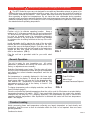
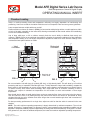
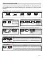
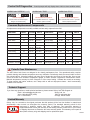
Model AFE Digital Series Lab Ovens
With Microprocessor Control & Digital Display
Quincy Lab, Inc.
OPERATING MANUAL
Standard Contents
(1) AFE Series Lab Oven
(2) Adjustable chrome wire shelf
(4) Shelf brackets
Not For Use With Flammable
Solvents or Gases.
Lab Oven
Model 30AFE
Quincy Lab,
POWER
Inc.
DIGITAL MICRO
PROCESSOR
Switch
opening
Menu
Enter/Exit
l
Menu Scrol
int
ecrease Setpo
Increase/D
CMW
MANU
STOP
TUNE
GCE SERIE
PF
E5GC
S
(PRESS)
OMRON
SPECIFICATIONS
INTERIOR DIMENSIONS
INCHES W x H x D
(CM) W x H x D
MODEL
10AFE
MODEL
20AFE
MODEL
30AFE
MODEL
40AFE
12x8.63x10
13x11.63x13
30.5x22x25.4 33x29.5x33
18x14.63x12 18x19.63x14
45.7x37x30.5 45.7x50x35.5
15x24.5x15
14x20.5x12
35.5x52x30.5 38x61x38
20x28.5x14
20x33.5x16
52x72.4x35.5 52x85x40.63
EXTERIOR DIMENSIONS
INCHES W x H x D
(CM) W x H x D
TEMPERATURE RANGE
Ambient + 25 F to: F / C
450 /232
450 /232
450 /232
450 /232
0.5 / 1.0
0.5 / 1.0
0.5 / 1.0
0.5 / 1.0
120/6.6*
800
5-15P*
120/8.8*
1050
5-15P*
120/12.5*
1500
5-15P*
120/12.5*
1500
5-15P*
44
38
61
54
78
70
94
85
CONTROL STABILITY
Typically +/- F / C
STANDARD ELECTRICAL
VOLTS/AMPS
WATTS
PLUG/NEMA
WEIGHT (lbs)
SHIPPING
STAND ALONE
* Standard models voltage only, optional 220 voltage available. Check label on back of unit.
Common Unit Construction
Exterior: Powder Coated Steel
Insulation: Fiberglass
Thermo-control: PID Microprocessor
Issue AFE 0415
Copyright Quincy Lab Inc. 2015
Interior: Aluminized Steel
Motor: Sleeve Bearing, Thermally Protected
Heater: Resistive-Tubular Incoloy
Quincy Lab Inc. 1925 N. Leamington Ave.
Chicago, Illinois
1-800-482-HEAT (4328)
PAGE 1
Safety Precautions
Read Operating Instructions Thoroughly Prior to Operation
The AFE Series lab ovens are not designed for use with any flammable solvents or gases or for
materials that may contain flammable solvents or gases. Use only a grounded outlet that is rated for
your model's electrical requirement. Oven exterior walls and doors may become hot to the touch
when operating at higher set temperatures. Do not leave the oven unattended during operation,
especially when processing materials that have flash point temperatures lower than the model oven's
maximum operating range. Do not modify the oven or control parameters to operate the oven above
the stated maximum operating temperature.
Set-up
Position unit in its ultimate operating location. Keep a
minimum of 2" of airspace around the unit and a minimum of
10" above the unit. Important: The exhaust ports should NOT
be used as chamber access for temperature-measuring
probes. Insertion of any such probe or device may damage
or unbalance the circulating fan blade at the top of the oven
chamber.
Install adjustable shelf by placing the ends of the wire shelf
bracket into the corresponding holes located on the inner
sides of the oven at the desired height. Push the ends of the
bracket into the holes until the first bends in the bracket are
against the wall, then rotate the bracket down. Place the
shelf on the brackets. (FIG 1)
A
B
C
D
FIG. 1
Plug the unit into a grounded outlet for your unit's rated
voltage.
General Operation
The unit is ready for your immediate use. All control
parameters, calibration and tuning has been done at the
factory, no adjustments are necessary.
Push the illuminated power button. The fan motor will start.
All LED's on the temperature control will light up immediately
and display the current chamber temperature and the set
temperature.
Set temperature is constantly displayed in the lower righthand corner of the display. To change the set temperature,
simply press either the up arrow key or the down arrow key,
until desired set temperature is reached (FIG 2). The
temperature control is set at the factory to read in 1/10
degree F or Fahrenheit units.
To change temperature units or display resolution, see Menu
Level Functions (page 3).
F
CMW
MANU
STOP
TUNE
PF
OMRON
E5GC
Enter/Exit Menu
Menu Scroll
Increase/Decrease Setpoint
(PRESS)
FIG. 2
Once the unit nears the desired temperature allow the unit to cycle for 20 minutes at set point before
temperature becomes fully stable. NOTE: Upon each initial powering-up, the control may typically
overshoot the set temp by 3 or 4 degrees especially if the temperature set point is close to the
operating ambient temperature. After equilibrium is achieved the control will hold set temperature
within 1 unit degree.
Chamber Loading
Article processing times and temperature uniformity are largely dependent on load density and
positioning. Load the oven so that air circulation within the oven is not impaired. Here are some
general guidelines:
Continued on insert....
PAGE 2
Model AFE Digital Series Lab Ovens
With Microprocessor Control & Digital Display
Quincy Lab, Inc.
OPERATING MANUAL INSERT
Chamber Loading
Article or media processing times and temperature uniformity are largely dependent on load density and
positioning. Load oven so that air circulation within the oven is not impaired. Here are some general guidelines:
Leave a space between multiple articles on a shelf.
Position articles on shelves as shown in (FIG 4), for best results avoid placing articles or media against or within
an inch of the walls, especially on the lower shelf, allowing unrestricted air flow around articles and contributing
to even and consistent heating.
Use of large solid trays, or foil on shelves severely limits the oven's ability to distribute heat evenly and
uniformly. (FIG 5) Since not enough heat rises within the chamber, thermometer readings give false indication
that temperature setting is too low. Higher temperature adjustments made as a result of these readings could
overheat the lower-placed articles or media.
Ideal
Circulation
Obstructed
Circulation
Heater
Rear fresh air
intake vents
FIG. 4
FIG. 5
Do not overload the unit with large (in quantity OR size), or high-density loads. This will show by non-uniform
processing and long or impossible "heat-through" times. To help determine a large load's suitability, compare the
time it takes for the temperature to recover to the original empty chamber set temperature once load is placed.
To reduce recovery time, reduce load accordingly. Also, large loads such as a beaker containing 2 liters of
solution, may require an elevated set temperature for the solution to reach and maintain a lower target
temperature.
Care should also be taken to avoid placing items on the top-most shelf too close to the holes in the fan plenum.
This will restrict the flow of air passing through the plenum and reduce the amount of pre-heated air being
circulated through the entire chamber and cause longer than normal heat-through times and inconsistent or
unstable oven temperatures.
For best processing performance for a single item, adjust one shelf so that the article is centered in the oven
chamber.
NOTE: The unit's minimum operating temperature is largely determined by ambient temperature. The unit can
operate 25 degrees F (approximately 14 degrees C) above room temperature but temperature stability may be
degraded. Temperature stability improves appreciably for settings that exceed ambient by 30 degrees F or better.
As a general rule, the lower the ambient temperature, the lower the maximum adjustable operating temperature.
Issue AFE 0714 Insert
Copyright Quincy Lab Inc. 2014
Menu Level Functions Guide
To access menu for common menu functions, please refer to Menu Guide below: Menu setting changes are
quick and easy with the our new 5-button digital microprocessor. Through the use of these controls you can:
set the operating temperaure, lock the set-temperature, select either degrees F or C, calibrate your unit to
your independent device, slect a different thermocouple type, and auto-tune your oven to your specific
application.
Digital Controller Function Buttons
PF
Enter / Exit MENU
MENU Scroll
To set setpoint temperature
Decrease
Increase
Up and down arrow
keys (shown left) are
used to increase or
decrease set-point
control temperature
as desired by user
To lock setpoint temperature
Hold together 3 seconds
Lock setpoint by
changing to '3'
Default set to 0
Changes digit
cursor on set
temperature
Decrease
Increase
To adjust control to read in C or F temperature units
Hold 3 sec.
View
Hit ONCE
Use
to
choose F or C
Default set to F
To calibrate control to independent probe/sensor
Hit ONCE
Hit ONCE
To calibrate oven,
add (or subtract)
the temperature
Use
keys to differential, to the
enter temperature existing iNS value
shift in degrees shown at prompt
To change thermocouple type
Hold 3 sec.
Use
keys
to change type
Default set to "J"
All Lab Series Ovens are factory equipped with a standard "J-type" thermocouple as the
default, but you may change from this type of thermocouple to either a different
thermocouple, RTD, or infrared sensor, depending on your particular application. Due to
the four-digit LED limit of the display, when changing to some of the alternate device
types, you may lose the decimal feature allowing you to view temperatures in tenths of a
degree.
To Auto-tune oven
Hit ONCE
All ovens are Auto-tuned at the factory using the 'At-1' option for faster response time.
You may, however, want to Auto-tune your oven to your specific application. To do this,
once at the 'At' prompt (at left), use arrow keys to initiate either Auto-tune option: 'At-1' (for
40% Auto-tune), or 'At-2' (for 100% Autotune). The 40% Auto-tune (At-1), will stabilize the
Use
keys to oven temperature quicker and with less 'overshoot' than the 100%, but will be somewhat
change setting
less precise. The 100% Auto-tune (At-2), will take longer to stabilize oven temperature
Default set to 40% but will be more precise, and take a little longer to complete the Auto-tune process.
PAGE 3
Control Self Diagnostics
ALARM Codes "S.ERR" & "- - - -"
Control prompts will only display when a fault or alarm condition exists.
ALARM Code "E111"
ALARM Code "E333"
or
Indicates Input Error
Check to make sure Thermocouple
wiring is connected securely
Indicates Internal Memory Error
Turn Controller OFF and On. If problem
remains, replace Controller
Indicates Internal Circuit Error
Turn Controller OFF and On. If problem
remains, replace Controller
Common Replacement Components
All replacement components are readily available and are easily replaced in the field.
COMPONENT
MODEL
VOLTAGE
PART #
COMPONENT
MODEL
VOLTAGE
PART #
Motor
All
115 Volt
205-2030
Digital Controller
All
All
401-1230
Motor
All
230 Volt
205-2031
Relay
All
All
401-1233
Rocker Switch
All
115 Volt
230 Volt
201-2213
201-2213-1
Fuse (10 amp)
10, 20
All
Q-1191
Thermocouple
All
All
701-6253
Fuse (15 amp)
30, 40
All
Q-1190
Friction Catch (set)
All
All
101-2221
Fuse Holder (red)
All
All
Q-1198
6' Cord & Plug
20, 30, 40
115 Volt
230 Volt
101-1403
101-1403-1
Wire Shelf
10
All
101-1000
6' Cord & Plug
10
115 Volt
230 Volt
101-1603
101-1603-1
Shelf Supports (2)
10
All
101-1001
Fan Blade
10
All
205-1018
Wire Shelf
20
All
201-2000
Fan Blade
20, 30
All
205-2018
Wire Shelf
30
All
101-3000
Fan Blade
40
All
205-3018
Wire Shelf
40
All
201-4000
Fan Blade 3" Heat Sink
All
All
205-4018
Shelf Supports (2)
20, 30, 40
All
101-3001
Periodic Oven Maintenance
The AFE Series Lab Ovens are designed to be virtually maintenance free. But operational safety requires
periodic cleaning and chamber temperature accuracy verification. Periodically check the rear air intake vents for
dirt or dust build-up. Keep the intake & exit ports clear of obstruction and clean of dust and dirt. Once a year,
check the actual oven chamber temperature against a known accurate temperature measurement device.
Maintain temperature accuracy to within 5 degrees F of the control setting. Calibrate the control as necessary.
To clean exterior and interior surfaces, use a damp cloth or with an all-purpose cleaner. Avoid commercially
available oven cleaners.
Technical Support
If you have any questions or need technical assistance, please contact Quincy Lab Tech Support at:
Email: [email protected]
Voice: 800-482-HEAT (4328)
Fax: 773-622-2282
Quincy Lab, Inc.
1925 N Leamington Ave
Chicago, Illinois 60639
Limited Warranty
Quincy Lab, Inc. warrants to the original purchaser that this product will be free from defects in material and
workmanship under normal use throughout the warranty period. The standard warranty period for this
instrument is eighteen months from date of shipment. The instrument warranty is
supplemented with a three year warranty on the heating element. Please refer to your invoice
or shipping documents to determine the active warranty period. This warranty covers parts &
labor (labor at factory only) and shipping cost for replacement parts.
PAGE 4