1
CW47 GPS Synchronized
Time Reference with
Integrated Antenna
User Manual
Bulletin
Revision
Date
NS37-UM
04
09 March 2012
TABLE OF CONTENTS
1. DESCRIPTION....................................................................................................................................................................4
1.1 Introduction..................................................................................................................................................... 4
1.2 Block Diagram................................................................................................................................................ 4
2. S
PECIFICATION.................................................................................................................................................................5
2.1 Performance .................................................................................................................................................. 5
2.2 CW47 Build Options....................................................................................................................................... 5
3. CONNECTOR INFORMATION & PIN-OUT DESCRIPTIONS............................................................................................6
3.1 Connector Information.................................................................................................................................... 6
3.2 Pin-Out Descriptions....................................................................................................................................... 6
4. OPERATION AND QUICK START......................................................................................................................................7
4.1 Operation and Quick Start.............................................................................................................................. 7
5. COMMUNICATIONS PROTOCOLS...............................................................................................................................8-19
5.1 Port Configurations......................................................................................................................................... 8
5.2 Output Format...........................................................................................................................................8-13
5.2.1 NMEA Messages................................................................................................................................... 8
5.2.1.1 GPGLL - Geographic Position, Lat/Lon.......................................................................................... 8
5.2.1.2 GPGGA - GPS Fix Data................................................................................................................. 9
5.2.1.3 GPGSA - GPS DOP and Active Satellites..................................................................................... 9
5.2.1.4 GPGSV - GPS Satellites in View.................................................................................................. 10
5.2.1.5 GPRMC - Recommended Minimum Data.................................................................................... 10
5.2.1.6 PVTG - Course Over Ground and Ground Speed........................................................................ 11
5.2.1.7 GPZDA - UTC Time and Date...................................................................................................... 11
5.2.1.8 POLYT - Time of Day.................................................................................................................... 11
5.2.1.9 POLYP- Position Data.................................................................................................................. 12
5.2.1.10 POLYS - Satellite Status............................................................................................................ 13
5.2.1.11 POLYI, Additional Information Message..................................................................................... 13
5.3 Command Format *...................................................................................................................................... 14
5.3.1 PRTH<Q|R>, VERS: Software Version................................................................................................ 14
5.3.2 PRTH<Q|S|R>, DYNA: Receiver Dynamics......................................................................................... 15
5.3.3 PRTH<Q|S|R>, ITIM: Initialize Time and Date..................................................................................... 15
5.3.4 PRTH<Q|S|R>, RSET: Re-Set the Receiver....................................................................................... 16
5.3.5 PRTH<Q|S|R>, INTM: Intermittent Operation Parameters.................................................................. 16
5.3.6 PRTH<Q|S|R>, ILLH: Initialized Lat, Long, Height Position................................................................. 17
5.3.7 PRTH<Q|S|R>, COMA: Coma Mode................................................................................................... 17
5.3.8 PRTH<Q|S|R>, FRQD: Frequency Output Select............................................................................... 17
5.3.9 PRTH<Q|S|R>, MMSV: Min & Max Satellites for a Position Solution.................................................. 18
5.3.10 PRTH<Q|S|R>, DRLM: Dead Reckoning Limit.................................................................................. 18
5.3.11 PRTH<Q|S|R>, ELVM: Satellite Elevation Mask................................................................................ 18
5.3.12 $PRTH<S|Q,R>, LOOP; CW47 Loop Back....................................................................................... 19
5.3.13 $PRTH<S|QR>,TMOD; CW47 Transit Mode..................................................................................... 19
5.3.14 $PRTHQ, STAT, RCL; CW47 Liu Status............................................................................................ 19
5.3.15 $PRTH<S|Q|R>SCLK; 2.048 MHz Synchronization Signal Output................................................... 19
CW47 Software User Manual
Copyright ©2012 NavSync Ltd. All Rights Reserved
Page 2 Rev 04 Date: 03/09/12
Specifications subject to change without notice.
TABLE OF CONTENTS
6.NMEA and UART Configuration Details....................................................................................................................20-21
6.1 NMEA Configuration Query ($PRTHQ, UxOP):............................................................................................ 20
6.2 NMEA Configuration Set ($PRTHS,UxOP):.................................................................................................. 20
6.3 UART Configuration Query ($PRTHQ, UxCM):............................................................................................ 21
6.4 UART Configuration Set ($PRTHQ,UxCM).................................................................................................. 21
APPENDIX 1....................................................................................................................................................................22-24
Graphical NS3Kview Software Installation..............................................................................................22-24
APPENDIX 2.........................................................................................................................................................................25
Programming Instructions............................................................................................................................. 25
APPENDIX 3....................................................................................................................................................................26-27
GPS Information......................................................................................................................................26-27
APPENDIX 4.........................................................................................................................................................................28
Bracket Installation....................................................................................................................................... 28
APPENDIX 5....................................................................................................................................................................29-31
Glossary..................................................................................................................................................29-31
APPENDIX 6.........................................................................................................................................................................31
Contact Details............................................................................................................................................. 31
APPENDIX 7.........................................................................................................................................................................32
Additional GPS Information.......................................................................................................................... 32
CW47 Software User Manual
Copyright ©2012 NavSync Ltd. All Rights Reserved
Page 3 Rev 04 Date: 03/09/12
Specifications subject to change without notice.
1. DESCRIPTION
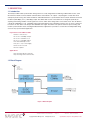
1.1 Introduction
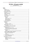
The NavSync CW47 GPS synchronization timing reference is a fully integrated unit combining a CW25 GPS receiver, active
GPS antenna, DC/DC converter, RS232 communications and G.703 E1 / T1 outputs – all packaged in a small, IP67 rated
waterproof plastic housing. The CW47 unit delivers undisturbed Stratum 1 synchronization when locked to GPS telecom format
G.703 E1 (2.048 Mbps) or T1 (1.544 Mbps) output. The CW25 GPS receiver in the CW47 unit, is designed specifically for
acquiring and tracking satellites in weak signal areas such as under dense foliage and in severe urban areas. The unit delivers
a G.703 E1 2.048 Mbps or a T1 1.544 Mbps output signal with different source impedance options such as 75 W or 120 W. The
E1 version can also deliver a G.703 part 10 2.048 MHz clock signal. The CW47 is the perfect solution for precise timing and
network synchronization needs, including broadband wireless applications. It provides a cost effective and independent timing
source for any synchronization application.
Key Features of the CW47 include:
• Stratum 1 Time Source
• G.703 E1 2.048 Mbps Output
• G.703 E1 2.048 MHz Clock
• G.703 T1 1.544 Mbps Option
• IP67 Rated Waterproof Box
• 48v (36v to 72v) Power Supply
• Short Circuit Protected
• RoHS Compliant
Applications:
• Synchronizing Wireless Networks
• Synchronizing Remote Switch Sites
1.2 Block Diagram
Figure 1 Block Diagram
CW47 Software User Manual
Copyright ©2012 NavSync Ltd. All Rights Reserved
Page 4 Rev 04 Date: 03/09/12
Specifications subject to change without notice.
2. CW47 GPS SENSOR SPECIFICATIONS
2.1 Performance
Module Rating
Physical
Sensitivity Acquisition Time
Power Interfaces General Supply Voltage Operating Temp
Storage Temp Humidity
Max Velocity/Altitude
Acquisition/Tracking
Hot Start
Stand Alone (Outdoor) Cold Warm Hot
1 Fix per Second Serial E1
Protocols
Receiver Type Processor IP67
36.0-72.0 VDC (48VDC Typical)
-30°C to +80°C
-55°C to +85°C
5% to 95% non-condensing
515ms-1/18,000m
-155dBm/-155dBm
Outdoor <2s
Indoor (-155dBm): <5s
<45s
<38s
<5s
Re-acquisition:<0.5s (90% confidence)
1.5 W typically
RS232, programmable baud - up to 115200 (default 38400)
G.703 2.048 Mbps clock signal (GPS driven)
120 W balanced (default) see Build Options Section
NMEA 0183, proprietary ASCII and
binary message formats
12 parallel channel x 32 taps up to 32 point FFT.
Channels, taps and FFT can be switched off to
minimize power or simulate simpler designs.
ARM 966E-S on a 0.18 micron process at up to 120 MHz.
Table 1 CW47 Specification
CW47 Output Format
The standard CW47 output is a 120 W balanced 2.048 Mbs clock signal as per ITU-T G.703(E12). This output can
be configured by a 2.048 MHz synchronization signal as per ITU-T G.703 (T12).
CW47 Build Options:
A 75 W unbalanced E1 version of the CW47 is also available, along with a T1-1.544Mbs version:
Option Description
1. Standard CW47, E1-2.048 Mbs G.703, 120 W balanced output
2. CW47 with E1, 2.048 Mbs G.703, 75 W unbalanced output
3. CW47 with T1, 1.544 Mbs G.703, DSX-1 (0 to 133 feet) output
CW47 Software User Manual
Copyright ©2012 NavSync Ltd. All Rights Reserved
Page 5 Rev 04 Date: 03/09/12
Specifications subject to change without notice.
3. CONNECTOR INFORMATION and PIN-OUT DESCRIPTIONS
3.1Connector Information
The connector used on the CW47 module is a metal male socket. It has an IP67 environmental protection rating. The circular
connector has a threaded joint according to IEC 60130-9/IEC 130-9. This is a Binder 423 series connector; part number 090173-90-08. A plastic protection cap hangs from this connector and can be mated to the metal connector, when the CW47 is
outdoors with no cable attached.
Please note that the standard unit does not come with any mating cable, thus the customer can connect with any cable type or
length required. A cable can be supplied with these units if requested. Please contact NavSync for more information.
A suitable mating connector can be bought from a number of manufacturers. A description of the mating part would be: IEC
60130-9/IEC 130-9 female 8 pole cable connector IP67 rated.
A list of compatible connector manufacturers is below along with part numbers. The manufacturers have other parts which will
also mate other then the part numbers listed below.
Manufacturer Series
Example Part Number
Binder
Lumberg
Amphenol
423 Series
03 Series
C 091 D
99-5172-15-08
0322-1 08-1
C091 31D008 100 2
These cable connectors should be wired using the numbering listed in Section 3.2.
3.2Pin-Out Descriptions
Pin 1
2
3
4
5
6
7
8
NAME
NC
RXD
GND
TRING
TXD
TTIP
V-
V+
Description
Not Connected
RS232, Receive to GPS
RS232, Reference for RS232 COMMS
Transmit TRING, G.703 E1 (T1) Output
RS232, Transmit from GPS
Transmit TTIP, G.703 E1 (T1) Output
Power input, Negative
Power input, Positive
Figure 2 CW47 Connector Pins (looking into the connector)
CW47 Software User Manual
Copyright ©2012 NavSync Ltd. All Rights Reserved
Page 6 Rev 04 Date: 03/09/12
Specifications subject to change without notice.
4. OPERATION and QUICK START
4.1 Operation and Quick Start
1. Place or mount the CW47 unit where it has a good view of the sky. A pole mounting bracket is available for the unit. This bracket works for 89-120mm diameter poles (contact NavSync for other mounting options). See Appendix 4 for details.
2. Attach a suitable cable assembly to the unit. The cable must mate with the 8 way male IEC 130-9 socket on the
CW47. A custom cable can be supplied if required, please contact NavSync for this.
The cable will provide the connection for:
• DC power(36 to 72V), between Pin 7(NEGATIVE) and Pin 8 (POSITIVE).
• RS232 interface (GPS TXD – Pin 5, GPS RXD – Pin 2, GND – Pin 3).
> This will enable the user to view the NMEA stream from the unit. The NMEA data gives informa-
tion such as, the quality of satellite signal strengths, type of GPS fix acquired, long/lat position and
time etc. A full description of these messages is in Section 8.2.1.
> The stream can be monitored using any terminal window utility or by using NavSync’s graphical
NS3Kview software. > The default baud rate is 38400, with 8 bits no parity, with no handshaking. > The user is able to issue commands to the CW47 unit. These commands can change the way the
unit operates. The commands can reset/restart the unit (RSET), change which NMEA messages
are outputted (U1OP) and the frequency of these messages, change the baud rate(U1CM) and
can check/test to operational status of the LIU (LOOP,TMOD,STAT). See Section 8.3 for more details.
> These commands can be sent easily with the graphical NS3Kview software.
• G.703 E1 output (TTIP-Pin 6, TRING-Pin4). This GPS driven G.703 2.048 Mbs is a 120 W balanced output.
Graphs showing the quality of the performance of the recovered clock signal are in CW47 Product Brief.
3. Apply the DC voltage (36 to 72VDC).
4. The unit should power up and start to stream NMEA data. The default baud rate is 38400.
5. Wait for GPS 3-D fix. This occurs when 4 or more satellites are being tracked with navigation data received. Refer
to the GPGSA and GPGSV for fix and satellite information. Refer to Section 8.2 for all GPS information on the
streaming NMEA messages.
6. The G.703 2.048 Mbs (1.544 Mbs) output will now be available on the TTIP-TRING signals.
CW47 Software User Manual
Copyright ©2012 NavSync Ltd. All Rights Reserved
Page 7 Rev 04 Date: 03/09/12
Specifications subject to change without notice.
5. COMMUNICATIONS PROTOCOLS
Full descriptions of the communications protocols used by the CW47 can be found in Sections 8.2 and 8.3.
5.1Port Configuration
The default baud rate on the standard CW47 version is 38400, this baud rate can be configured to another value using the
$PRTHS, U1CM command. See Section 9.2 for more details on this. The port is also configured to be: 8 bits no parity, with no
handshaking
5.2 Output Format
The NMEA sentences are output in ASCII and described below.
5.2.1 NMEA Messages
There are two main types of sentence, ‘Approved’ and ‘Proprietary.’ All sentences start with $ delimited with commas and ending with <CR><LF>. Approved sentences are recognized by the first 5 characters after the $, which define both the kind of
talker providing the information (2 characters, GP in the case of a GPS), and the type of information (3 characters).
Proprietary sentences are indicated by a P following the $, as the first of the 5 characters, the next 3 indicating the manufacturer (from a listing of mnemonic codes), and the 5th character being selected by that manufacturer for the particular sentence structure. Proprietary sentences must conform to the general NMEA structures, but are otherwise undefined outside of
the Manufacturers own documentation.
The following Approved messages are available from the CW47 receiver. Messages can be enabled/disabled by using the
$PRTHS, U1OP command in Section 6.4
Approved NMEA messages
GPGLL - Geographic position - latitude longitude [enabled by default]
GPGGA - Global positioning system fix data [enabled by default]
GPGSA - GNSS DOP and active satellites [enabled by default]
GPGSV - GNSS satellites in view [enabled by default]
GPRMC - Minimum required sentence [enabled by default]
GPVTG - Velocity and track over ground [disabled by default]
GPZDA - Date and time [disabled by default]
POLYT - NavSync proprietary time of day message [enabled by default]
POLYP - NavSync proprietary status message [disabled by default]
POLYS - NavSync proprietary satellite status message (GPGGA + GPGSV) [disabled by default]
POLYI - NavSync proprietary net assist information message [disabled by default]
5.2.1.1 GPGLL - Geographic Position, Lat/Lon
Latitude and longitude, with time of position fix and status.
$GPGLL,Latitude,N,Longitude,E,hhmmss.sss,Status,Mode*cs
Name
Description
$GPGLL
Latitude
N Longitude
E hhmmss.sss
Status
Mode
Cs NMEA sentence header (Position Data)
User datum latitude degrees, minutes, decimal minutes format (ddmm.mmmmmm)
Hemisphere ‘N’= North, or ‘S’ = South
User datum longitude degrees, minutes, decimal minutes format (dddmm.mmmmmm)
Longitude direction ‘E’= East, or ‘W’ = West
UTC time in hours, minutes, seconds and decimal seconds format.
StatusV=navigation receiver warning, A=data valid
Mode indicator:A=Valid, Autonomous, D=Valid, Differential, E=Invalid, Estimated, N=Invalid, Not valid
Message checksum in hexadecimal
CW47 Software User Manual
Copyright ©2012 NavSync Ltd. All Rights Reserved
Page 8 Rev 04 Date: 03/09/12
Specifications subject to change without notice.
5. COMMUNICATIONS PROTOCOLS continued
5.2.1.2 GPGGA - GPS Fix Data
Time and position, together with GPS fixing related data.
$GPGGA,hhmmss.sss,Latitude,N,Longitude,E,FS,NoSV,HDOP,Altref,M,msl,M,DiffAge,DiffStation*cs
Name
Description
$GPGGA
hhmmss.sss
Latitude
N Longitude
E FS NoSv
HDOP
AltRef
M msl
M DiffAge
DiffStation
cs NMEA sentence header (position data)
UTC time in hours, minutes, seconds and decimal seconds format.
User datum latitude degrees, minutes, decimal minutes format (ddmm.mmmmmm)
Hemisphere ‘N’= North, or ‘S’ = South
User datum longitude degrees, minutes, decimal minutes format (dddmm.mmmmmm)
Longitude direction: ‘E’= East, ‘W’ = West
Fix Status:
0 No Fix
1 Standard GPS
2 Differential GPS
Number of satellites used in the position solution
2-D Horizontal Dilution of Precision (0.00 to 99.99)
Altitude (meters) above user datum ellipsoid
Units of height (meters)
Mean Sea Level
Units of Mean Sea Level (meters)
Age of differential correction
Differential base station ID
Message checksum in hexadecimal
5.2.1.3 GPGSA - GPS DOP and Active Satellites
GPS receiver operating mode, satellites used for navigation, and DOP values.
$GPGSA,Smode,FS,sv,sv,sv,sv,,,,,,,,PDOP,HDOP,VDOP*cs
Name
Description
$GPGSA
Smode
FS sv PDOP
HDOP
VDOP
cs NMEA sentence header (Satellite Data)
A= Automatic switching 2D/3D M=Manually fixed 2D/3D
Fix Status:
1 No fix
2 2D GPS Fix
3 3D GPS Fix
Satellites in use, null for unused fields (12 available fields)
3-D position dilution of precision (0.00 to 99.99)
2-D horizontal dilution of precision (0.00 to 99.99)
Vertical dilution of precision (0.00 to 99.99)
Message checksum in hexadecimal
CW47 Software User Manual
Copyright ©2012 NavSync Ltd. All Rights Reserved
Page 9 Rev 04 Date: 03/09/12
Specifications subject to change without notice.
5. COMMUNICATIONS PROTOCOLS continued
5.2.1.4 GPGSV - GPS Satellites in View
The number of satellites in view, together with each PRN, elevation and azimuth, and C/No value. Up to four satellite
details are transmitted in one message, with up to three messages used as indicated in the first field.
$GPGSV,NoMsg,MsgNo,NoSv{,sv,elv,az,cno}{,sv,elv,az,cno….}*cs
Note: {} designate optional sections that appear only if there is satellite data.
Name
Description
$GPGSV
NoMsg
MsgNo
NoSv
sv elv az cno
cs NMEA sentence header (satellite data)
Total number of GPGSV messages being output
Number of this messages
Number of satellites in view
Satellites ID
Satellite elevation angle (degrees)
Satellite azimuth angle (degrees)
Satellite signal/Noise ration (dB/Hz)
Message checksum in hexadecimal
5.2.1.5 GPRMC - Recommended Minimum Data
The ‘Recommended Minimum’ sentence is defined by NMEA for GPS/Transit system data.
$GPRMC,hhmmss.sss,status,latitude,N,Hemisphere,longitude,E,spd,cmg,ddmmyy,mv,mvd,Mode*cs
Name
Description
$GPRMC
hhmmss.sss
status
Latitude
N Longitude
E spd
cmg
ddmmyy
mv mvd
Mode
cs NMEA sentence header (Recommended Minimum Sentence)
UTC time in hours, minutes, seconds.
Status:V=navigation receiver warning, A=data valid
User datum latitude degrees, minutes, decimal minutes format (ddmm.mmmmmm)
Hemisphere: ‘N’= North, or ‘S’ = South
User datum longitude degrees, minutes, decimal minutes format (dddmm.mmmmmm)
Longitude direction: ‘E’= East, ‘W’ = West
Speed over ground (knots).
Course made good
Date in day, month year format
Magnetic variation
Magnetic variation direction
Mode indicator: D = Valid, Differential, A = Valid, Autonomous, E = Invalid, Estimated, N = Invalid, Not valid
Message checksum in hexadecimal
CW47 Software User Manual
Copyright ©2012 NavSync Ltd. All Rights Reserved
Page 10 Rev 04 Date: 03/09/12
Specifications subject to change without notice.
5. COMMUNICATIONS PROTOCOLS continued
5.2.1.6 GPVTG - Course Over Ground and Ground Speed.
Velocity is given as course over ground (COG) and ground speed
$GPVTG,cogt,T,cogm,M,knots,N,kph,K,Mode*cs
Name
Description
$GPVTG
cogt
T cogm
M knots
N kph
K Mode
cs NMEA sentence header (speed and heading)
Course over ground (true)
True - fixed field
Course over ground (magnetic)
Magnetic - fixed field
Speed over ground (knots)
Knots - fixed field
Speed over ground (kph)
Kilometers per hour – fixed field
Mode Indicator:D = Valid, Differential, A = Valid, Autonomous, E = Invalid, Estimated, N = Invalid, Not Valid
Message checksum in hexadecimal
5.2.1.7 GPZDA - UTC Time and Date
This message transfers UTC time and date. Since the latency of preparing and transferring the message is variable,
and the time does not refer to a particular position fix, the seconds’ precision is reduced to 2 decimal places.
$GPZDA,hhmmss.sss,dd,mm,yyyy,Int,Unsigned*cs
Name
Description
$GPZDA
hhmmss.sss
dd mm
yyyy
Int Unsigned
Int Unsigned
kph
K cs NMEA sentence header (time and date)
UTC time in hours, minutes, seconds.
UTC day
UTC month
UTC year
Local zone hours
Local zone minutes
Speed over ground (kph)
Kilometers per hour – fixed field
Message checksum in hexadecimal
Proprietary NMEA Messages
5.2.1.8 POLYT - Time of Day
$POLYT,hhmmss.sss,ddmmyy,UTC_TOW,week,GPS_TOW,Clk_B,Clk_D,PG,LocalTTag,BAcc,TAcc,BLANK*cs
Name
Description
$POLYT
hhmmss.sss
ddmmyy
UTC_TOW
week
GPS_TOW
Clk_B
Clk_D
PG
LocalTTag
BAcc
TAcc
cs NavSync proprietary NMEA sentence header (position data)
UTC time in hours, minutes, seconds and decimal seconds format.
Date in day, month, year format.
UTC time of week (seconds with microseconds resolution)
GPS week number (continues beyond 1023)
GPS time of week (seconds with microseconds resolution)
Receiver clock bias (nanoseconds)
Receiver clock drift (nanoseconds/second)
1PPS granularity (nanoseconds)
Local receiver time-tag since start-up [msec]
Bias accuracy
Time accuracy
Message checksum in hexadecimal
CW47 Software User Manual
Copyright ©2012 NavSync Ltd. All Rights Reserved
Page 11 Rev 04 Date: 03/09/12
Specifications subject to change without notice.
5. COMMUNICATIONS PROTOCOLS continued
5.2.1.9 POLYP- Position Data
$POLYP,hhmmss.sss,Latitude,N,Longitude,E,AltRef,FS,Hacc,Vacc,SOG,COG,V_vel,ageC,HDOP,VDOP,PDOP,GDOP,
TDOP,GU,RU,DR*cs
Name
Description
$POLYP
hhmmss.sss
Latitude
N Longitude
E AltRef
FS Hacc
Vacc
SOG
COG
V_vel
ageC
HDOP
VDOP
PDOP
TDOP
GU
RU
DR
cs NavSync proprietary NMEA sentence header (position data)
UTC time in hours, minutes, seconds and decimal seconds format.
User datum latitude degrees, minutes, decimal minutes format (ddmm.mmmmmm)
Hemisphere: ‘N’= North, ‘S’ = South
User datum longitude degrees, minutes, decimal minutes format (dddmm.mmmmmm)
Longitude direction: ‘E’= East, ‘W’ = West
Altitude (meters) above user datum ellipsoid.
Fix Status:
NF = No fix DR = Predictive dead reckoning solution
DA = Predictive dead reckoning solution with DR aiding
G1 = Partial GPS solution with DR aiding
G2 = Stand alone 2D solution G3 = Stand alone 3D solution D1 = Partial differential GPS solution with DR aiding
D2 = Differential 2D solution D3 = Differential 3D solution
Horizontal (2 sigma) accuracy estimates (0 to 99999 meters)
Vertical (2 sigma) accuracy estimates (0 to 99999 meters)
Speed over ground (knots) (0.000 to 999.999 knots)
Course over ground (true) in degrees (0.00 to 359.99 degrees)
Vertical (positive Up) velocity (m/s) (0.000 to 999.999 m/s)
Age of most recent DGPS corrections applied (seconds).(00.00 to 99.99 = none available)
2-D horizontal dilution of precision (00.00 to 99.99)
Vertical dilution of precision (00.00 to 99.99).
3-D position dilution of precision (00.00 to 99.99)
Time dilution of precision (00.00 to 99.99)
Number of GPS satellites used in the navigation solution
Number of GLONASS satellites used in the navigation solution
Dead reckoning aiding status bits (in ASCII Hex)
bit 0
Altitude position aiding applied
bit 1
Vertical velocity aiding applied
bit 2
(GPS-GLONASS) time difference aiding applied
bit 3
External distance travelled input used
bit 4
External speed input used
bit 5
External track input used
bit 6
External delta -track input used
bit 7,8
Reserved for future use
Message checksum in hexadecimal
CW47 Software User Manual
Copyright ©2012 NavSync Ltd. All Rights Reserved
Page 12 Rev 04 Date: 03/09/12
Specifications subject to change without notice.
5. COMMUNICATIONS PROTOCOLS continued
5.2.1.10 POLYS - Satellite Status
$POLYS,GT{,ID,s,AZM,EL,SN,LK}{,ID,s,AZM,EL,SN,LK}{,ID,s,AZM,EL,SN,LK}{,ID,s,AZM,EL,SN,LK},ID,s,AZM,EL,S
N,LK}{,ID,s,AZM,EL,SN,LK}{,ID,s,AZM,EL,SN,LK}{,ID,s,AZM,EL,SN,LK}{,ID,s,AZM,EL,SN,LK}{,ID,s,AZM,EL,SN,LK}
{,ID,s,AZM,EL,SN,LK}{,ID,s,AZM,EL,SN,LK}*cs
Note: {} designate optional sections that appear only if there is satellite data
Name
Description
$POLYS
GT
ID s AZM
EL SN
LK cs NavSync proprietary NMEA sentence header (satellite data)
Number of GPS satellites tracked
Satellite PRN number (1-32)
Satellite status
- = not used U = used in solution
e = available for use, but no ephemeris
Satellite azimuth angle (range 000 - 359 degrees)
Satellite elevation angle (range 00 - 90 degrees)
Signal to noise ratio in (range 0 - 55 dB/Hz)
Satellite carrier lock count (range 0 - 255 seconds)
0 = code lock only
255 = lock for 255 or more seconds
Message checksum in hexadecimal
5.2.1.11 POLYI, Additional Information Message
$POLYI,JN,jammer,EXT{,efields},INT{,ifields},BLANK*cs Note: More than one {efield} or {ifield} may be present, each separated by commas.
Name
Description
$POLYI
JN jammer
EXT
efields
INT
ifields
BLANK
cs NavSync proprietary NMEA sentence header (additional information)
Fixed descriptor field
Detected jammer to noise ratio [dB/Hz]
Fixed descriptor field, indicates the use of externally provided ancillary measurements e.g.
received from network assistance. All comma separated fields following, up to the INT field
descriptor, are externally provided measurements
DIFF = Differential inputs
TSYNC = Time synchronization
CLKB = Clock bias
FREQ = Frequency (of reference oscillator)
HPOS = Horizontal position VPOS = Vertical position (altitude)
VVEL = Vertical velocity
DIST = Distance moved
SPEED = Current speed
TRACK = Current track
DTRACK = Delta track (change in direction)
Fixed descriptor field, indicates the use of internally provided ancillary measurements e.g.
retrieved from non volatile memory. All comma separated fields following, are internally
provided measurements
TSYNC = Time synchronization
CLKB = Clock bias
FREQ = Frequency (of reference oscillator)
HPOS = Horizontal position VPOS = Vertical position (altitude)
VVEL = Vertical velocity
DIST = Distance moved
SPEED = Current speed
TRACK = Current track
DTRACK = Delta track (change in direction)
Reserved for future use
Message checksum in hexadecimal
CW47 Software User Manual
Copyright ©2012 NavSync Ltd. All Rights Reserved
Page 13 Rev 04 Date: 03/09/12
Specifications subject to change without notice.
5. COMMUNICATIONS PROTOCOLS continued
5.3 Command Format *
The NavSync CW47 receiver has a unique set of proprietary commands.
Commands will only be accepted on Port 1.
The commands to and from the unit have the following general formats:
$PRTH<Q|S|R>,<id>,<msg fields>[*<checksum>]<cr><lf>
Where:
< |Q|S|R> is the single ASCII character as follows:
Q: Command, a query command to the CW47 receiver.
S: Command, requires the CW47 receiver to set system settings.
R: Response to a CW47 receiver, response to a $PRTH query or an acknowledgement of a $PRTH Set.
<id> is a 4 character command identifier.
<msg fields> are the message fields for the message and are all positional. Optional or unknown fields are shown as nulls
(ie adjacent commas). Trailing commas to the end of a message (ie nothing but null message fields) are not required.
*<checksum> An optional checksum byte for checking accuracy defined as follows:
The checksum is displayed as a pair of ASCII characters, (0-9 and A-F inclusive) whose value represents the “HEX” value of
the checksum byte. When used, it always appears as the last field of the sentence and is prefixed by field delimiter “*” (HEX 2A)
instead of “,” and followed by <CR><LF> (HEX 0D 0A). The checksum value is calculated by XOR’ing (exclusive OR’ing also
known as Modulo 2 Sum) the 8 binary data bits of each valid data character in the sentence between the “$” (HEX 24) and “*”
(HEX 2A) characters.
The “$” (HEX 24) and the “*” (HEX 2A) characters are not included in the checksum.
<cr><lf> are the ASCII codes 0Dh and 0Ah (carriage return and line feed) respectively.
Some commands use multiple sentences to transfer data: multiple sentence transfer shall be accomplished by means of 2 fields
within the sentence for which this format is used:
t: Total number of sentences forming the data transfer (minimum value 1)
x: ID number of the current sentence ranging from 1 to t inclusive
Null fields within a command shall be interpreted as “use current value” where appropriate. Null fields must be delimited
by adjacent commas when they exist between two non-null fields. If all trailing fields after a given field are null, further
commas are not required.
*Note:
For CW47, the standard CW25 commands include:
VERS DYNA ITIM RSET INTM ILLH COMA FRQD IDNO ZONE
Unique command only to the CW47 includes:
LOOP, TMOD, RCL, SCLK
As well as the NMEA and UART configuration commands
UxOP, UxCM
The accuracy testing of INTM command is not yet implemented. Additional commands, some documented here, can be enabled with custom
firmware. Further customization is also available. Please consult the factory for details.
5.3.1 PRTH<Q|R>, VERS: Software Version
Purpose
This message queries and responds with the current software version information.
Query Format
$PRTHQ,VERS[*checksum]<cr><lf>
Response /Acknowledge Format
$PRTHR,VERS,Build_Name,Version_Number,Version_Date,Version_Time, Serial_Num, BB_Releaset*<checksum><cr><lf>
Explanation of Parameters
Build_Name
Product name Version_Number software version number
Version_Date Software
Version_Time
Serial_Num
BB_Release Build date in mmm_dd_yyyy format where Mmm is the three character abbreviation of the month name
Software build time in hh:mm:ss format
Product serial number is current not implemented and always outputs “Serial_Num”
Baseband version number
CW47 Software User Manual
Copyright ©2012 NavSync Ltd. All Rights Reserved
Page 14 Rev 04 Date: 03/09/12
Specifications subject to change without notice.
5. COMMUNICATIONS PROTOCOLS continued
5.3.2 PRTH<Q|S|R>, DYNA: RECEIVER DYNAMICS
Purpose
This message sets, queries and responds to the receiver host dynamics and hence the maximum receiver tracking
dynamics expected.
The degree of filtering performed by the navigation and timing Kalman filter is dependant on the selected receiver platform.
Query Format
$PRTHQ,DYNA[*checksum]<cr><lf>
Set Format
$PRTHS,DYNA,platform[*checksum]<cr><lf>
Response / Acknowledge Format
$PRTHR,DYNA,platform*<checksum><cr><lf>
Explanation of Parameters
platform receiver platform (integer, range 0 – 10) 0
= Fixed base station, timing and frequency modes etc
1
= Stationary, but unknown position 2
= Man pack / walking
3
= Automotive / land vehicle
4
= Marine
5
= Airborne, low dynamics (<1g) — Limit of CW47
Default for CW47 is 1 and changes to 0 after 10 minute location survey completed, maximum is 5.
5.3.3 PRTH<Q|S|R>, ITIM: INITIALIZE TIME AND DATE
Purpose
This message sets, queries and responds to the user initialized time and date. Two input options are available, one
allowing a calendar date and GMT time to be input and the other a GPS week number and seconds of week.
The input date is acted upon regardless and is primarily used to set the GPS week inside the receiver. The time input will
not be used if is set to zero, or if the receiver is currently tracking any satellites and therefore already has a good submillisecond knowledge of time.
If the time input is not used then the response message returns the values used or assumed instead of those input. The
time RMS accuracy is used to decide how much importance to put on the input values and should be set with care.
Query Format
$PRTHQ,ITIM[*checksum]<cr><lf>
Set Format
Using a GMT time format
$PRTHS,ITIM,timeRMS,GMT,day,month,year,[hours],[minutes],[seconds] [*checksum]<cr><lf>
Using a GPS time format
$PRTHS,ITIM,timeRMS,GPS,gps_week,[gps_time][*checksum]<cr><lf>
Response / Acknowledge Format
$PRTHR,ITIM,timeRMS,GMT,day,month,year,hours,minutes,seconds,GPS, gps_week,gps_time*<checksum><cr><lf>
Explanation of Parameters
time RMS
RMS accuracy of the input time-tag (seconds)
(floating point, range 0 – 999999.0)
day
day of month (integer, range 1 – 31)
month
month of year (integer, range 1 – 12)
year
4 digit year (integer, range 1980 – 2047)
hours
hours of day (integer, range 0 – 23)
minutes
minutes of hour (integer, range 0 – 59)
seconds
seconds of minute (floating point, range 0 – 59.999)
gps_week
GPS week number, including pre GPS roll-over weeks, eg 1037 (integer, range 0 – 32768)
gps_TOW
GPS time of week in seconds (floating point, range 0.0 –604800.0)
CW47 Software User Manual
Copyright ©2012 NavSync Ltd. All Rights Reserved
Page 15 Rev 04 Date: 03/09/12
Specifications subject to change without notice.
5. COMMUNICATIONS PROTOCOLS continued
5.3.4 PRTH<Q|S|R>, RSET: RE-SET THE RECEIVER
Purpose
This message sets, queries and responds to a receiver re-set command with optional actions such as clearing specific
data groups stored in the CW47 local EEPROM.
The data areas that can be cleared include satellite almanacs, ephemerides, network assist and receiver configuration
parameters.
Note that “sleep” mode is not currently supported in the CW47 technology.
This command invokes a 2 second time-out prior to the reset being called.
Query Format
$PRTHQ,RSET[*checksum]<cr><lf>
Set Format
$PRTHS,RSET,{[option],[option],….}[*checksum]<cr><lf>
Response / Acknowledge Format
$PRTHR,RSET,{[option],[option],….}*<checksum><cr><lf>
A response option of NO, indicates that no reset command is currently activated.
Explanation of Parameters
Option
A list of character descriptors to indicate which, if any, of the optional actions are to be undertaken prior to the software
re-sets.
”CONFIG” = clear the receiver configuration data stored in EEPROM.
”EPH” = clear the satellite ephemeris data stored in EEPROM.
”ALM” = clear the satellite almanac data stored in EEPROM.
”SLEEP” = Enter a “sleep” mode, still to be defined.
5.3.5 PRTH<Q|S|R>, INTM: INTERMITTENT OPERATION PARAMETERS
Purpose
This message queries, sets and respond with the fix interval, run duration, run interval, horizontal and vertical accuracy
masks for intermittent operation. Once the receiver has met the required horizontal and vertical accuracy masks it will
go to sleep until the next run interval. The receiver will also go to sleep if no fix or the accuracy masks have not been met
within the run duration.
Query Format
&PRTHQ, INTM [*checksum]<cr><lf>
Set Format
$PRTHS, INTM, Fix_Interval, Run_Duration, Run_Interval, Horizontal_Acc_Mask, Vertical_Acc_Mask[*checksum]<cr><lf>
Response / Acknowledge Format
$PRTHR, INTM*<checksum><cr><lf>
Explanation of Parameters
Fix_Interval
Interval in ms between adjacent fixes
Run_Duration
Maximum time in ms to attempt to obtain fix. Must be greater than Fix_Interval
and is 0 for continuous operation
Run_Interval
Time interval in ms between waking to obtain a fix. Must be greater than Run_Duration
Horizontal_Acc_Mask
Required horizontal accuracy in meters before run completes. Zero disables vertical
accuracy testing.
Vertiacl_Acc_Mask
Required vertical accuracy in meters before run completes.
Zero disables vertical accuracy testing.
CW47 Software User Manual
Copyright ©2012 NavSync Ltd. All Rights Reserved
Page 16 Rev 04 Date: 03/09/12
Specifications subject to change without notice.
5. COMMUNICATIONS PROTOCOLS continued
5.3.6 PRTH<Q|S|R>, ILLH: INITIALIZED LAT, LONG, HEIGHT POSITION
Purpose
This message sets, queries and responds to the initialized geodetic position (latitude, longitude, ellipsoidal height and
antenna height above the reference marker) in the receiver’s current user datum.
The position RMS accuracy is used to decide how much importance to put on the input values and should be set with care.
Query Format
$PRTHQ,ILLH[*checksum]<cr><lf>
Set Format
$PRTHS,ILLH,LatDeg,LatMin,LatSec,LatH,LonDeg,LonMin,LonSec,LonH,EllHt,AntHt,posRMS [*checksum]<cr><lf>
Response / Acknowledge Format
$PRTHR,ILLH,LatDeg,LatMin,LatSec,LatH,LonDeg,LonMin,LonSec,LonH,EllHt,AntHt,posRMS*<checksum><cr><lf>
Explanation of Parameters
LatDeg
Latitude degrees (floating point, range ±90.0)
LatMin
Latitude minutes (floating point, range ±59.999999)
LatSec
Latitude seconds (floating point, range ±59.99999)
LatH
Latitude hemisphere (char ‘N’ or ‘S’)
LonDeg
Longitude degrees (floating point, range ±90.0)
LonMin
Longitude minutes (floating point, range ±59.999999)
LonSec
Longitude seconds (floating point, range ±59.99999)
LonH
Longitude hemisphere (char ‘E’ or ‘W’)
EllHt
Height of the reference marker above the current user datum reference ellipsoid in meters
(floating point, range ±18,000.0)
AntHt
Height of the antenna phase center above the reference marker height defined by EllHt above in
meters (floating point, range ±18,000.0)
posRMS
RMS accuracy of the input position (meters)
(floating point, range 0 - 999999.0)
Note that since the degree, minutes and seconds fields will accept floating point values then a decimal degree value, or and integer degree, decimal minute
value can be input directly by setting the minutes and seconds fields to zero as appropriate (eg 52.12345678,0,0,N or 52,14.123456,0,N).
5.3.7 PRTH<Q|S|R>, COMA: COMA MODE
Purpose
This message sets, queries and responds coma mode. Coma mode puts the receiver to sleep for a predetermined period
of time.
Query Format
$PRTHQ,COMA[*checksum]<cr><lf>
Set Format
$PRTHS,COMA,Period[*checksum]<cr><lf>
Response / Acknowledge Format
$PRTHR,COMA,Period*<checksum><cr><lf>
Explanation of Parameters
Period The period in milliseconds that the receiver will sleep.
5.3.8 PRTH<Q|S|R>, FRQD: FREQUENCY OUTPUT SELECT
Purpose
This message sets, queries and responds the frequency output. Outputs the requested frequency out of the CW25 receiver
to the E1 LIU. The frequency is set at the default 2.048Mhz and should not be modified, doing so would stop the LIU from
operating correctly.
Query Format
$PRTHQ,FRQD[*checksum]<cr><lf>
Set Format
$PRTHS,FRQD,Frequency[*checksum]<cr><lf>
Response / Acknowledge Format
$PRTHR,FRQD,Frequency*<checksum><cr><lf>
Explanation of Parameters
Frequency The frequency in Megahertz that the receiver will output. CW47 defaults to 2.048 MHz
CW47 Software User Manual
Copyright ©2012 NavSync Ltd. All Rights Reserved
Page 17 Rev 04 Date: 03/09/12
Specifications subject to change without notice.
5. COMMUNICATIONS PROTOCOLS continued
5.3.9 PRTH<Q|S|R>, MMSV: MIN & MAX SATELLITES FOR A POSITION SOLUTION
Purpose
This message sets, queries and responds to the minimum and maximum number of satellites the receiver will use for
a position solution. Increasing the minimum number of satellites will improve the accuracy achieved when sufficient
satellites are available, but may reduce the time when a solution can be produced. Reducing the maximum number of
satellites may reduce the accuracy of the position solution, but will decrease the amount of processing power required for
the solution.
Note that setting the maximum satellites to less than 4 will prevent the receiver from performing a 3D position solution.
Likewise setting the minimum number of satellites greater than 3 will prevent the receiver performing a 2-D, altitude fixed
solution.
The maximum must be greater than or equal to the minimum number of satellites.
Query Format
$PRTHQ,MMSV[*checksum]<cr><lf>
Set Format
$PRTHS,MMSV,[min_NSV],[max_NSV][*checksum]<cr><lf>
Response / Acknowledge Format
$PRTHR,MMSV,min_NSV,max_NSV*<checksum><cr><lf>
Explanation of Parameters
min_NSV
Minimum satellites used for a position / time solution (integer, range 0-12)
max_NSV Maximum satellites used for a position / time solution (integer, range 0-12)
5.3.10 PRTH<Q|S|R>, DRLM: DEAD RECKONING LIMIT
Purpose
This message sets, queries and responds to the limit for the forward predictive dead reckoning, after the last valid fix
(epochs). The dead reckoning will progress at constant velocity for the first half of this period and then reduce to a
standstill during the second half.
Note that since this value has units of epochs, it will have a different effect on a 1Hz CW47 receiver to that on a 2Hz, 5Hz
or 10Hz CW47 receivers.
Query Format
$PRTHQ,DRLM[*checksum]<cr><lf>
Set Format
$PRTHS, DRLM,DR_Limit[*checksum]<cr><lf>
Response / Acknowledge Format
$PRTHR, DRLM, DR_Limit*<checksum><cr><lf>
Explanation of Parameters
DR_Limit
Number of epochs to dead reckon for (integer, range 0 –32768)
5.3.11 PRTH<Q|S|R>, ELVM: SATELLITE ELEVATION MASK
Purpose
This message sets, queries and responds to the satellite elevation mask angle below which satellite data will not be used
in the navigation and time solution.
Query Format
$PRTHQ,ELVM[*checksum]<cr><lf>
Set Format
$PRTHS,ELVM,nvElevMask[*checksum]<cr><lf>
Response / Acknowledge Format
$PRTHR,ELVM,nvElevMask*<checksum><cr><lf>
Explanation of Parameters
nvElevMask The navigation and time solution elevation mask angle in degrees (integer, range 0 –90).
CW47 Software User Manual
Copyright ©2012 NavSync Ltd. All Rights Reserved
Page 18 Rev 04 Date: 03/09/12
Specifications subject to change without notice.
5. COMMUNICATIONS PROTOCOLS continued
5.3.12 $PRTH<S|Q,R>, LOOP; CW47 LOOP BACK
Loop Command is Setting the E1 LIU in the Following Loop Modes:
1. Local loop. Loops back the LIUs transmit data only, to the receive section of the LIU device.
2. Analogue loop. Loops back the LIUs transmit data, clock and carrier, to the receive section of the LIU device.
3. No loop. No loop-back to receive LIU section. It represents the default settings
General Loop Command Format:
$PRTH<S|Q>,LOOP,<LOCAL|ANALOGUE|NO_LOOP><CR><LF>
General Reply Format:
$PRTHR,LOOP,<LOCAL|ANALOGUE|NO_LOOP ><CR><LF>
5.3.13 $PRTH<S|QR>, TMOD; CW47 TRANSMIT MODE
Transmit command is setting the E1 LIU in the following transmit modes:
1. Transmit PRBS
2. Transmit alternating ones and zeros
3. Transmit unframed all ones
General Transmit Mode Command Format:
$PRTH<S|Q>,TMOD,<PRBS|ZERO_ONES|ALL_ONES><CR><LF>
General Reply Format:
$PRTHR,TMOD,< PRBS|ZERO_ONES|ALL_ONES ><CR><LF>
5.3.14 $PRTHQ, STAT, RCL; CW47 LIU STATUS
Status command polls the status of the LIU RCL (Receive Carrier Loss) and PBEO (PRBS Bit Error Output) lines. The command is useful and to be used in conjunction with different loop back and transmit modes for in field or manufacturing debug.
General status query of the E1 LIU RCL and PBEO lines:
General Format:
$PRTHQ,STAT<CR><LF>
General Reply Format:
$PRTHR,STAT,RCL=<HIGH|LOW>,PBEO=<HIGH|LOW><CR><LF>
The default loop mode for DS21348 is “no loop mode” while the transmit mode is “Transmit PRBS”.
Example Command:
$PRTHQ,STAT<CR><LF>
Example Reply:
$PRTHR,STAT,RCL=HIGH,PBEO=HIGH*37
PBEO is HIGH, if out of synchronization
RCL is HIGH, when there is a receive carrier loss
EG. If analog loop back is enabled and PRBS is transmitting, then both the RCL and PBEO should be LOW (no carrier
loss is detected or no PRBS error is detected). With the default, no loop, both of these will be HIGH (no carrier or no
data being received, as the RTIP and RRING pins of the of the LIU are unconnected).
5.3.15 $PRTH<S|Q|R>SCLK; 2.048 MHz Synchronization Signal Output
The output can be configured, to change the output from a 2.048 Mbps to a 2.048 MHz synchronization signal as per
ITU-T G.703 (T12). The user should know that once a cold start (config) command is given to the unit the output will
return back to the default output (2.048Mbps).
General Format:
$PRTH<S|Q|R>,,SCLK,<HIGH|LOW> <CR><LF>
General Reply Format:
$PRTHR,SCLK,<HIGH|LOW> <CR><LF>
Example Query Command:
$PRTHQ,SCLK<CR><LF>
Example Reply:
$PRTHR, SCLK,SCLK,LOW *37
Here the output is the default 2.048Mbs G.703 signal
Example Set- Enable 2.048Mhz Output
$PRTHS, SCLK,HIGH <CR><LF>
CW47 Software User Manual
Copyright ©2012 NavSync Ltd. All Rights Reserved
Page 19 Rev 04 Date: 03/09/12
Specifications subject to change without notice.
6. NMEA and UART CONFIGURATION DETAILS
This section describes how the NMEA and UART output can be configured for different refresh rates, contents and baud rates.
• NMEA Output Configuration (i.e. output frequency) Query:
$PRTHQ, U1OP
• NMEA Output Configuration (i.e. output frequency) Set:
$PRTHS, U1OP
• UART Configuration (i.e. baud rate) Query:
$PRTHQ, U1CM
• UART Configuration (i.e. baud rate) Set:
$PRTHS, U1CM
6.1 NMEA Configuration Query ($PRTHQ, UxOP):
The command takes the form “$PRTHQ,UxOP” where x is a port number. The port number will always be 1 on the CW47.
The remainder of the strings is of the form “$PRTHR,UxOP,GLL=1,GSV=4,PLT=1” where x is the port number for which the
information was requested. The specific contents supported are dependent on the NMEA sentences supported by the system.
Only the settings which are to be altered need to be listed. A NMEA checksum of the form “*4D” is appended to the output string.
The list of currently supported NMEA sentences is as shown below. To turn a sentence output off completely, specify zero as the
duration for that command. Subsequent commands may reassign an output period to sentences disabled in this way, effectively
re-enabling the output sentence. This command also supports a shortcut by means of an “ALL” specifier. When this is encountered, the period specified is applied to all sentences. An example of this is shown below, where every message output on port1
will be printed at a 5-second period with the exception of the GPRMC sentence, which will be output every second, and the
POLYT sentence, which will be disabled.
$PRTHS, U1OP, ALL=5, RMC=1. PLT=0
An example response string is shown below. In this example, all sentences are output every second, except GPGSV, which is
output every three seconds, and POLYT, which is not output at all (i.e. the sentence output is disabled).
$PRTHR,U1OP,GLL=1,RMC=1,VTG=1,GGA=1,GSA=1,GSV=3,PLT=0,PLP=1,PLS=1,PLI=1*0C
6.2 NMEA Configuration Set ($PRTHS,UxOP):
The command takes the form “$PRTHS,UxOP,GLL=2,GGA=4,GSV=0” where x is a port number. On the CW47 platform, the
port number is always between 1 and 3 inclusive.
The remainder of the string is of the form “GLL=1,GSV=4,PLT=1”. The specific contents supported are dependent on the NMEA
sentences supported by the system. Only the settings which are to be altered need to be listed. A NMEA checksum of the form
“*4D” is appended to the output string.
The list of currently supported NMEA sentences are as shown above for the query command. To turn a sentence output off
completely, simply specify zero as the duration for that command. Subsequent commands may reassign an output period to
sentences disabled in this way, effectively re-enabling the output sentence. This command also supports a shortcut by means of
an “ALL” specifier. When this is encountered, the period specified is applied to all sentences. An example of this is shown below,
where every message output on port 1 will be printed at a 5-second period with the exception of the GPRMC sentence, which
will be output every second, and the POLYT sentence, which will be disabled.
$PRTHS,U1OP,ALL=5,RMC=1,PLT=0
CW47 Software User Manual
Copyright ©2012 NavSync Ltd. All Rights Reserved
Page 20 Rev 04 Date: 03/09/12
Specifications subject to change without notice.
6. NMEA and UART CONFIGURATION DETAILS continued
6.3 UART Configuration Query ($PRTHQ, UxCM):
The command takes the form “$PRTHQ,UxCM” where x is a port number. On the CW47 platform, the port number is always
between 1 and 3 inclusive.
The response string is of the form “$PRTHR,UxCM,38400,38400,N,1” where x is the port number for which the information was
requested. The remainder of the string, “38400,38400,N,1” represents the port Tx baud rate, Rx baud rate, parity and stop bits
respectively. A NMEA checksum of the form “*4D” is appended to the output string.
Although the format of the command supports the use of different Rx and Tx baud rates, this is not currently supported by the
CW47 platform. Consequently, the Rx and Tx baud rates returned will always be identical.
6.4 UART Configuration Set ($PRTHQ,UxCM)
The command takes the form “$PRTHS,UxCM,57600,57600,N,1” where x is a port number. On the CW47 platform, the port
number is always between 1 and 3 inclusive.
The remainder of the string, “57600,57600,8,N,1” represents the port Tx baud rate, Rx baud rate, parity and stop bits respectively.
Although the format of the command supports the use of different Rx and Tx baud rates, this is not currently supported by the
CW47 platform. Consequently, the Rx and Tx baud rates must always be specified to be the same value. In addition, the CW47
platform does not currently support the use of parity, or of stop bit settings other than 1 stop bit. The supported baud rates are:
1200, 2400, 4800, 9600, 19200, 38400, 57600, 115200, and 230400.
If a command is issued which is badly formatted or does not adhere to these constraints, it will be discarded. This command is
intended for use with the NMEA port(s) only. Caution should be exercised when using this command to change the baud rate on
other ports, since data may be lost during the configuration change.
It should be noted that these commands allow the system to be configured at 1200 baud, while requesting that the full set of
NMEA sentences be output each second. Such configurations will result in NMEA corruption since the output NMEA data rate
exceeds the underlying baud rate.
CW47 Software User Manual
Copyright ©2012 NavSync Ltd. All Rights Reserved
Page 21 Rev 04 Date: 03/09/12
Specifications subject to change without notice.
APPENDIX 1
NMEA Viewer – NS3Kview - Installation and Set-up
1.1 Graphical NS3Kview Software Installation
1.
2.
Execute the “NS3KviewInstaller.exe” installation file, by double clicking.
This file can be found on the NavSync CD or www.navsync.com
Follow the on-screen instructions to complete installation
3. The graphical NS3Kview software shortcut will be available from the computers desktop.
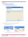
1.2 Graphical NS3Kview Software Communication Setup for the CW47
• Double click the NS3Kview desktop icon to run utility.
• Click “Settings” and then “Communications”.
•
For the CW47, the baud rate is 38400. Select the com port that is connected to the CW47.
CW47 Software User Manual
Copyright ©2012 NavSync Ltd. All Rights Reserved
Page 22 Rev 04 Date: 03/09/12
Specifications subject to change without notice.
APPENDIX 1 continued
•
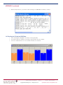
With the unit powered on, you should see data streaming in the ‘NMEA Monitor Window’, as below.
1.3 Checking for 3D Lock on NS3KView
•
•
•
Once streaming bars will appear in the window called signal quality.
These bars indicate the satellites in view and the signal strength from these satellites.
A 3D lock is obtained when four or more satellites turn blue, as seen below:
CW47 Software User Manual
Copyright ©2012 NavSync Ltd. All Rights Reserved
Page 23 Rev 04 Date: 03/09/12
Specifications subject to change without notice.
APPENDIX 1 continued
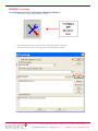
1.4 Commanding the CW47 with Graphical NS3Kview Software
•
Click on the “Configure GPS Receiver” icon below.
•
•
The following image shows the version query command being given to the CW47.
The response from the CW47 shows up in the ‘Command Response’ window.
CW47 Software User Manual
Copyright ©2012 NavSync Ltd. All Rights Reserved
Page 24 Rev 04 Date: 03/09/12
Specifications subject to change without notice.
APPENDIX 2
CW47 Programming Instructions
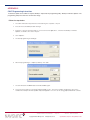
If a firmware update for the CW47 is required, NavSync will provide the programming utility, “NavSync Firmware Updater”. The
programming utility will contain the new firmware image.
Follow the steps below:
1. The CW47 will need to be powered on and streaming the computers com port.
2. Execute the received file by double-clicking it.
3. Select the com port, which the CW47 is connected. No other applications, other than the NavSync Firmware Updater, should be connected to this port.
4. Click “Update”.
5. The flash programming should begin.
6. When the programming is complete (as below), click “Quit”.
7. The unit will restart and NMEA data should be available again.
8. Check the version with the command: $PRTHQ,VERS<cr><lf>. The version number should be the same as the
number in the NavSync firmware updater utility. See Appendix 1 on how to do this using graphical NS3Kview software.
CW47 Software User Manual
Copyright ©2012 NavSync Ltd. All Rights Reserved
Page 25 Rev 04 Date: 03/09/12
Specifications subject to change without notice.
APPENDIX 3
GPS Information
GLOBAL POSITIONING SYSTEM (GPS)
The Global Positioning System (GPS) is a military satellite based navigation system developed by the U.S. Department of Defence, which is also made freely available to civil users.
Civilian use of GPS is made available at the user’s own risk, subject to the prevailing DOD policy or limitations, and to individuals understanding of how to use the GPS.
In today’s satellite constellation there are a minimum of 24 operational satellites (plus several operational spares) in 6 orbital
planes, at an altitude of about 22,000 km. The GPS system can give accurate 3-D position, velocity, time, and frequency, 24
hours a day, anywhere around the world. GPS satellites transmit a code for timing purposes, and also a ‘navigation message’,
which includes their exact orbital location and system integrity data. Receivers use this information, together with data from their
internal almanacs, to precisely establish the satellite location. The receiver determines position by measuring the time taken for
these signals to arrive. At least three satellites are required to determine latitude and longitude if your altitude is known (e.g. a
ship at sea), and at least a fourth to obtain a 3-D fix.
GPS Positioning and Navigation
The CW47 receiver needs to be able to see at least 4 satellite vehicles (SV’s) to obtain an accurate 3-D position fix. When
travelling in a valley or built-up area, or under heavy tree cover, it can be difficult to acquire and maintain a coherent satellite lock. Complete satellite lock may be lost, or only enough satellites (3) tracked to be able to compute a 2-D position fix
or even a poor 3D fix due to insufficient satellite geometry (i.e. poor DOP). Inside a building or beneath a bridge, it probably will not be possible to update a position fix. The receiver can operate in 2-D mode if it goes down to seeing only 3 satellites by assuming its height remains constant. But this assumption can lead to very large errors, especially when a change
in height does occur. A 2-D position fix is not to be considered a good or accurate fix; it is simply “better than nothing”.
The receiver’s antenna must have a clear view of the sky to acquire satellite lock. It is the location of the antenna that will
be given as the position fix. If the antenna is mounted on a vehicle, survey pole, or backpack, allowance for this must be
made when using the solution.
To measure the range from the satellite to the receiver, two criteria are required: signal transmission time, and signal reception time. All GPS satellites have several atomic clocks that keep precise time and these are used to time-tag the message and control the transmission sequence of the coded signal.
The receiver has an internal clock to precisely identify the arrival time of the signal. Transit speed of the signal is a known
constant (the speed of light), therefore: time x speed of light = distance.
Once the receiver calculates the range to a satellite, it knows that it lies somewhere on an imaginary sphere whose radius
is equal to this range. If a second satellite is then found, a second sphere can again be calculated from this range information. The receiver will now know that it lies somewhere on the circle of points produced where these two spheres intersect.
When a third satellite is detected and a range determined, a third sphere would intersect the area formed by the other two.
This intersection occurs at just two points. The correct point is apparent to the user, who will at least have a very rough
idea of position. A fourth satellite is then used to synchronize the receiver clock to the satellite clocks.
In practice, just 4 satellite measurements are sufficient for the receiver to determine a position, as one of the two points
will be totally unreasonable (possibly many kilometers out into space).
This assumes the satellite and receiver timing to be identical. In reality, when the CW47 receiver compares the incoming
signal with its own internal copy of the code and clock, the two will no longer be synchronized. Timing error in the satellite
clocks, the receiver, and other anomalies, mean that the measurement of the signals transit time is in error. This effectively, is a constant for all satellites, since each measurement is made simultaneously on parallel tracking channels. Because
of this, the resultant ranges calculated are known as “pseudo-ranges”.
To overcome these errors, the CW47 receiver then matches or “skews” its own code to become synchronous with the
satellite signal. This is repeated for all satellites in turn, thus measuring the relative transit times of individual signals. By
accurately knowing all satellite positions, and measuring the signal transit times, the user’s position can be accurately
determined.
Utilizing its considerable processing power, the CW47 receiver rapidly updates these calculations from satellite data to
provide a real time position fix.
CW47 Software User Manual
Copyright ©2012 NavSync Ltd. All Rights Reserved
Page 26 Rev 04 Date: 03/09/12
Specifications subject to change without notice.
APPENDIX 3 continued
Standard Positioning Service (SPS)
Civil users worldwide are able to use the SPS without restriction or charge.
Dilution Of Precision (DOP) is a measure of the satellite geometry, and is an indicator of the potential quality of the
solutions. The lower the numerical value, the better the potential accuracy (for example, a PDOP below 3 indicates
good satellite geometry). For 3-D positioning, fluctuations in DOP can be harmful to the solution, especially in kinematic/dynamic modes.
The following DOP terms are computed by CW47:
HDOP Horizontal Dilution of Precision
(Latitude, Longitude)
VDOP Vertical Dilution of Precision
(Height)
TDOP Time Dilution of Precision (Timing errors)
PDOP Position Dilution of Precision
(3-D positioning)
GDOP Geometric Dilution of Precision
(3-D position & Time)
Estimated accuracy = DOP x measurement accuracy
While each of these terms can be individually computed, they are formed from co-variances, and are not independent of
each other. For example, a high TDOP will cause receiver clock errors that will eventually result in increased position errors.
Horizontal accuracy figure of 95% is the equivalent to 2RMS (twice root-mean-square), or twice the standard deviation radial
error.
Similarly, for vertical and time errors, a figure of 95% is the value of 2 standard deviations of vertical or time error.
Root-mean-square (RMS) error is the value of one standard deviation (67%) of error.
Circular Error Probability (CEP) is the value of the radius of a circle, centred at a position containing 50% of the position
estimates. Spherical Error Probability (SEP) is the spherical equivalent of CEP, which is centred at a position containing
50% of the position estimates.
CEP and SEP are not affected by large errors, which could make the values an overly optimistic measurement. These
probability statistics are not suitable for use in a high accuracy positioning system. The CW47 reports all accuracy’s in the
form of a standard deviation (RMS) value.
Precise Positioning Service (PPS)
This service is only available to authorized users with cryptographic equipment and special receivers. Access is limited to the
U.S. and allied military, U.S. Government agencies, and selected civil users specifically approved by the U.S. Government.
CW47 Software User Manual
Copyright ©2012 NavSync Ltd. All Rights Reserved
Page 27 Rev 04 Date: 03/09/12
Specifications subject to change without notice.
APPENDIX 4
Bracket Installation
Bracket contains:
Fasteners:
4 M3x10 Socket Cap Screws (No1) 2 M6x10 Socket Cap Screws (No2) 2 M6x140 Socket Cap Screws (No3)
2 M6 Spacers
Bracket Pieces:
2 80x30mm Brackets (A)
1 145x150mm Bracket (B)
1 45x154mm Bracket (C)
Installation steps:
1.Fix bracket Pieces B +C to the pole with the two long screws (No. 3). Spacers can be used, if needed, for the smaller
pole diameters.
2. Fix the two small bracket pieces (A) to the CW47 unit, using the four small screws (No. 1).
3. Attach the CW47-bracket assembly to the pole assembly using the two medium size screws (No. 2). Adjust position of
CW47, with these two screws, such to optimize the sky-view.
CW47 Software User Manual
Copyright ©2012 NavSync Ltd. All Rights Reserved
Page 28 Rev 04 Date: 03/09/12
Specifications subject to change without notice.
APPENDIX 5
Glossary
2D
3D
AGC
Almanac
Antenna
ASCII
Baud
BIT
CDU
CEP
Channel
CMOS
C/No
COM Port
CONUS
CPU
CTS
Datum
Delta range
DOD
DOS
DOP
DR
DSR
DTR
ECEF
Ellipsoidal
Height
EMI/EMS/EMC EPS
ENU
Ephemeris
Firmware
GDOP
Geoid
Geoid/Ellipsoid Two-Dimensional
Three Dimensional (i.e. including altitude)
Automatic Gain Control
Data transmitted by each satellite, and which provides the approximate orbital information of all the GPS satellites constellation (i.e. a ‘timetable’).
Also called ‘Aerial’, the device for receiving the radio signals.
A standard digital format for alpha-numeric characters (American Standard Code for Information Interchange).
Serial digital communication speed units (bits per second).
Built in Test
Control-Display Unit
Circular Error Probability
The satellite tracking unit of a GPS receiver. One channel may track more than one satellite, by multiplexing, but for best performance each satellite should be continuously tracked by a dedicated channel so more than one channel is often integrated into a receiver.
A type of semiconductor fabrication process (Complementary Metal Oxide Semiconductor), resulting in low power. CMOS devices require static protection during handling.
Carrier to Noise ratio (a measure of signal quality)
Communication port, e.g. PC serial communication ports COM1 etc.
Continental United States
Central Processing Unit (usually the microprocessor)
Clear to Send (serial communication handshaking)
The reference shape of the Earth’s surface used in the construction of a map or chart. Usually chosen for a ‘best fit’ over the area of interest and thus the Datum for various parts of the world may differ.
Small changes in range between a satellite and the receiving antenna.
US Department of Defense
Disk Operating System.
A DOP (Dilution of Position) is a figure which represents the purely geometrical contribution of the satellites’
positions to the total position error budget. Low values of a DOP (1 - 5) mean that the calculated position
should be good whilst higher DOP values indicate a greater uncertainty in the determined position. Good
DOP values are obtained when satellites are well spaced geometrically, whilst poor values result from
available satellites all being visible in similar directions. When the DOP value is excessive (e.g. > 100) then
neither stand-alone nor differential positions should be used.
Dead Reckoning - a means of estimating present position based on a known starting position updated by
applying distance and direction of the user’s movements.
Data Set Ready (serial communication handshaking)
Data Terminal Ready (serial communication handshaking)
Earth Centered Earth Fixed.
Height as defined from the Earth’s centre by a reference
ellipsoid model (see Datum)
Electromagnetic Interference (emitted from equipment), Susceptibility (to interference from other equipment), and Compatibility (EMI + EMS)
Emergency Power Supply, only for maintaining the RTC data in the RAM when the equipment is powered down
East North Up (the order of listing co-ordinates)
Similar to Almanac, but providing very accurate orbital data of each individual satellite and transmitted by
the satellite concerned
Program resident within the receiver.
Geometrical Dilution of Precision
The Mean Sea Level surface of the Earth
Difference between the Mean Sea Level and the separation mathematical model used to define a datum, at the point of interest
CW47 Software User Manual
Copyright ©2012 NavSync Ltd. All Rights Reserved
Page 29 Rev 04 Date: 03/09/12
Specifications subject to change without notice.
APPENDIX 5 continued
Glossary continued…
GHz
GMT
GPS
GPS time
Hex
HDOP
IC
ICD
I/O
IODE
IRQ
Kalman Filter
knot
L1
L-band
Lithium
LMT
mA
Macro
MHz
mph
MSL
MIL-STD
Multiplexing
NMEA
NMEA 0183
OTF
n.mile
ns, nSec
PC
PCB
P-code
PDOP pps, PPS
PRN
Pseudo Range PSU
RAM
Real Numbers Resolution
RF
RFI
RMS
Gigahertz, one thousand MHz (i.e. 109 Hz)
Greenwich Mean Time (similar to UTC)
Global Positioning System
Time standard for the GPS system (seconds are synchronous with UTC)
Denotes a number in hexadecimal format
Horizontal Dilution of Precision
Integrated Circuit
Interface Control Document
Input - Output
Issue of Data Ephemeris
Interrupt Request
Mathematical process used to smooth out measurement errors of pseudo-ranges and carrier phases of
tracked satellites. For example ‘8 states’ refers to filtering of position and time (i.e. x, y, z and t) and the rate of change of each
Nautical mile per hour
The 1575.42 MHz frequency radiated by GPS satellites
The band of radio frequencies between 1 and 2 GHz
A metallic element (used in batteries)
Local Mean Time
Milliamp (of current)
Text containing frequently used operations which can be executed as a single command (DM only)
Megahertz, i.e. one million cycles per second
Miles per Hour
Mean Sea Level = geoidal height = 0
Military Standard
A receiver channel can track multiple satellites by switching rapidly between them so as to gather all data transmissions
National Marine Electronics Association
A serial communication standard defining hardware compatibility, message formats, and a range of
standard messages
On-The-Fly carrier phase ambiguity resolution. The ability to resolve integer carrier phase ambiguities in real-time while moving
International Nautical Mile (1852 meters; 6076.1 feet, 1.15 statute miles)
Nanosecond, one thousandth of a microsecond (i.e. 10-9 second)
Personal Computer (IBM compatible)
Printed Circuit Board
The Precise (or Protected) GPS code - not available to civil users
Position Dilution of Precision, including horizontal and vertical components
Pulse per Second, and Precise Positioning Service
Pseudo-Random Noise code unique to each satellite’s message and therefore used to identify each satellite
The apparent measured ‘straight line’ distance from a satellite to the receiving antenna at any instant in
time, including any errors caused by satellite clocks, receiver clocks, refraction of the radio waves, etc.
Power Supply Unit
Random Access Memory
Numbers which may have decimal point and fractional component
Smallest separation of two display elements
Radio frequency
Radio Frequency Interference
Root Mean Square
CW47 Software User Manual
Copyright ©2012 NavSync Ltd. All Rights Reserved
Page 30 Rev 04 Date: 03/09/12
Specifications subject to change without notice.
APPENDIX 5 continued
Glossary continued…
RPS
RS232
RS422
RTCM
RTC
RTK
RTS
RXD
S/A
SEP
SMA
SPS
SSR
SV
TNC
TSPI
TTL
TTFF
TXD
us, uSec
UTC
UTM
UART
VDOP
WGS
Relative Positioning System
Serial communication hardware standard (+/- 12v nom.)
A serial communication hardware standard (differential)
Radio Technical Committee for Maritime Services
Real-time Clock (maintaining approximate time when unit is off)
Real Time Kinematic
Request to Send (serial communication handshaking)
Receive Data (serial communication to Data Terminal or ‘DTE’ from Data Communication Equipment or DCE’)
Selective Availability - imposed by the DOD to limit the GPS performance available to civil users.
Spherical Error Probability
Miniature threaded coaxial connector.
Standard precision Service
Solid State Recorder
Satellite Vehicle
A standard threaded coaxial connector
Time Space Position Information
Transistor-transistor Logic (family of digital electronic components)
Time to First Fix
Transmit Data (serial communication from Data Terminal or ‘DTE’ to Data Communication Equipment or ‘DCE’)
Microsecond (u is frequently used for the Greek µ symbol denoting ‘micro’, one millionth part, 10-6)
Coordinated Universal Time
Universal Transverse Mercator
Universal Asynchronous Receiver-transmitter (used in serial communications)
Vertical Dilution of Precision
World Geodetic System (a world-wide Datum, GPS works in WGS84 which has superseded WGS72)
APPENDIX 6
Contact Details
For further details and hotline support please contact:
North American Sales
NavSync Ltd.
2111 Comprehensive Dr, Aurora, IL 60505, USA
Telephone:
+1 630 236-3026 Facsimile:
+1 630 236-3023 International Sales and Support
NavSync Ltd.
BAY 143, Shannon Industrial Estate,
Shannon, Co. Clare, Ireland
Telephone:
+353 61 472221
Facsimile:
+353 61 472226
CW47
User
Manual
APPENDIX 7
Additional GPS Information
U.S. Coast Guard Navigation Center
Civilian GPS service notices, general system information, and GPS outage reporting:
www.navcen.uscg.gov
U.S. Naval Observatory
General USNO information and links to USNO timing and other useful sites:
www.usno.navy.mil
NavSync GPS Homepage
www.NavSync.com
General GPS Information and links to other useful GPS sites:
USAF GPS Wing
www.losangeles.af.mil
National Marine Electronics Association (NMEA)
For information on the NMEA protocol specification:
www.nmea.org
General GPS Information
Glossary of GPS terms:
www.gpsworld.com/resources/glossary.htm
Revision
Revision Date
Notes
R00
R01
R02
R03
R04
05/05/09
06/03/09
09/08/09
05/25/11
03/09/12
Initial Release
Appendix 4 added
Communication Protocol Revisions
Specification Updates
Power Specification Updated to 1.5W Typically
NavSync, Ltd.
Europe
Bay 143
Shannon Industrial Estate
Shannon, Co. Clare, Ireland
Phone: +353 61 475 666
E-mail: [email protected]
North America
2111 Comprehensive Drive
Aurora, IL 60505, USA
Phone: 630.236.3026
E-mail: [email protected]
www.NavSync.com