1
AD51H-BASIC
Programming Manual
(Command)
-QD51
-QD51-R24
-A1SD51S
-AD51H-S3
• SAFETY PRECAUTIONS •
(Always read these instructions before using this equipment.)
Before using this product, please read this manual and the relevant manuals introduced in this manual
carefully and pay full attention to safety to handle the product correctly.
The instructions given in this manual are concerned with this product. For the safety instructions of the
programmable controller system, please read the CPU module user's manual.
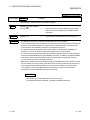
In this manual, the safety instructions are ranked as "DANGER" and "CAUTION".
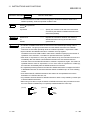
DANGER
Indicates that incorrect handling may cause hazardous conditions,
resulting in death or severe injury.
! CAUTION
Indicates that incorrect handling may cause hazardous conditions,
resulting in medium or slight personal injury or physical damage.
!
Note that the ! CAUTION level may lead to a serious consequence according to the circumstances.
Always follow the instructions of both levels because they are important to personal safety.
Please save this manual to make it accessible when required and always forward it to the end user.
[Design Precautions]
!
DANGER
• Make sure to configure the interlock line outside the PLC system so that the system always
operates normally when changing the data and control status of the PLC being operated from a
peripheral device.
Moreover, determine in advance how the system handles with communication errors by poor
cable connection, etc. that may occur when performing online operations on the PLC CPU from
a peripheral device.
!
CAUTION
• Please read this manual thoroughly and confirm the safety before starting online operations
(especially forced outputs and operating status modifications) performed by connecting a
peripheral device to the operating CPU module.
Incorrect online operations may cause damage to the machinery or result in accidents.
A-1
A-1
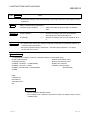
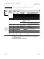
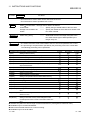
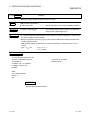
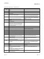
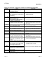
REVISIONS
* The manual number is given on the bottom left of the back cover.
Print Date
Apr., 2000
Sep., 2000
* Manual Number
SH(NA)-080090-A First printing
SH(NA)-080090-B Additions
Revision
PCRD instruction processing code 516,
PCWT instruction processing code 516
Oct., 2003
SH(NA)-080090-C
Additions
Regarding compiler BASIC, Chapter 5, Chapter 11 (ON COM GOSUB
instruction, PCWT instruction, ZCNTL instruction, ZMESSAGE GET
instruction), Appendix 4.4.2
Correction
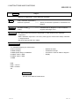
WARRANTY
Oct., 2006
SH(NA)-080090-D
Additions
About difference between modules, Appendix 8
Correction
How to use this manual, Regarding Compiler BASIC, Chapter 1,
Section 2.1, 2.5, Chapter 3, Section 3.3.2, 3.11, 3.13.1, 3.13.2,
Section 4.2.2, Section 6.2, Section 7.1, 7.2.1, 7.3.1 to 7.3.4, Section 8.1,
Chapter 11, Appendix 1.2, 1.3, 4.1, 4.4, 4.4.2
Deletion
Section 3.13.3
Japanese Manual Version SH-080094-D
This manual confers no industrial property rights or any rights of any other kind, nor does it confer any patent
licenses. Mitsubishi Electric Corporation cannot be held responsible for any problems involving industrial property
rights which may occur as a result of using the contents noted in this manual.
© 2000 MITSUBISHI ELECTRIC CORPORATION
A-2
A-2
INTRODUCTION
Thank you for purchasing the MELSEC-Q, A series PLC.
Please read this manual carefully so that equipment is used to its optimum.
CONTENTS
SAFETY PRECAUTIONS..............................................................................................................................A- 1
REVISIONS ..................................................................................................................................................A- 2
CONTENTS ..................................................................................................................................................A- 3
How to use this manual..................................................................................................................................A-13
Regarding Compiler BASIC ...........................................................................................................................A-13
About Module Names ....................................................................................................................................A-13
About differences between modules .............................................................................................................A-14
1 OVERVIEW
1- 1 to 1- 3
1.1 Features .................................................................................................................................................. 1- 2
1.2 Symbols Used in This Manual................................................................................................................ 1- 3
2 THE BASICS OF AD51H-BASIC
2- 1 to 2- 24
2.1 Preparation to Use AD51H-BASIC......................................................................................................... 2- 1
2.2 Direct Mode and Program Mode ............................................................................................................ 2- 4
2.3 Line Format ............................................................................................................................................. 2- 4
2.4 Spaces and Keywords ............................................................................................................................ 2- 5
2.5 Characters Used in BASIC ..................................................................................................................... 2- 6
2.6 What are Instructions and Functions?.................................................................................................... 2- 9
2.7 Constants ................................................................................................................................................ 2-10
2.7.1 Character string constants ............................................................................................................... 2-10
2.7.2 Numeric constants............................................................................................................................ 2-10
2.7.3 Single-precision and double-precision numeric constants ............................................................. 2-11
2.8 Variables.................................................................................................................................................. 2-12
2.8.1 Variable names and type declaration characters............................................................................ 2-12
2.8.2 Array variables.................................................................................................................................. 2-13
2.8.3 Special variables (How to use B@ and W@) ................................................................................. 2-14
2.9 Type Conversion ..................................................................................................................................... 2-17
2.10 Expressions and Operators .................................................................................................................. 2-18
2.10.1 Arithmetic operators ....................................................................................................................... 2-18
2.10.2 Relational operators ....................................................................................................................... 2-20
2.10.3 Logical operators............................................................................................................................ 2-21
2.11 Character String Operations................................................................................................................. 2-23
2.12 Priority Order of Operations.................................................................................................................. 2-24
A-3
A-3
3 LET'S CREATE AND EXECUTE A PROGRAM
3- 1 to 3- 46
3.1 Creating a Program................................................................................................................................. 3- 3
3.2 Executing and Editing a Program........................................................................................................... 3- 5
3.2.1 Executing a program ........................................................................................................................ 3- 5
3.2.2 If an error occurs .............................................................................................................................. 3- 5
3.2.3 Editing a program ............................................................................................................................. 3- 6
3.3 Saving and Loading a Program.............................................................................................................. 3-10
3.3.1 Memory cards used for AD51H-BASIC (AD51H-S3 only).............................................................. 3-10
3.3.2 Saving a program ............................................................................................................................. 3-11
3.3.3 Loading programs ............................................................................................................................ 3-15
3.4 Organizing Memory Cards and FDs....................................................................................................... 3-16
3.4.1 Displaying file names ....................................................................................................................... 3-16
3.4.2 Renaming files.................................................................................................................................. 3-18
3.4.3 Deleting files ..................................................................................................................................... 3-19
3.5 Specifying Data ....................................................................................................................................... 3-20
3.5.1 Assignment statements.................................................................................................................... 3-20
3.5.2 Preparing groups of data ................................................................................................................. 3-21
3.6 Jumps and Loops.................................................................................................................................... 3-23
3.6.1 Jump unconditionally........................................................................................................................ 3-23
3.6.2 Jump depending on a value............................................................................................................. 3-23
3.6.3 Loop for the number of times specified ........................................................................................... 3-24
3.6.4 Loop while a certain condition is met............................................................................................... 3-25
3.7 Letting BASIC Make Decisions .............................................................................................................. 3-26
3.7.1 Condition specification ..................................................................................................................... 3-26
3.7.2 Judgment instructions ...................................................................................................................... 3-27
3.8 How to Use Arrays .................................................................................................................................. 3-29
3.8.1 Number of dimensions in an array................................................................................................... 3-30
3.9 Using Subroutines................................................................................................................................... 3-31
3.10 Displaying Characters on the Screen................................................................................................... 3-32
3.10.1 Functions for displaying characters ............................................................................................... 3-33
3.10.2 Displaying characters to an arbitrary position ............................................................................... 3-35
3.11 Entering Data Using the Keyboard....................................................................................................... 3-37
3.12 Printing to the Printer ............................................................................................................................ 3-39
3.13 Character Processing ........................................................................................................................... 3-40
3.13.1 Types of characters........................................................................................................................ 3-40
3.13.2 Half-byte character unit processing ............................................................................................... 3-40
3.14 About Types of Numeric Relationships................................................................................................ 3-43
3.15 Executing a Large Program by Dividing it up....................................................................................... 3-44
A-4
A-4
4 THE EXCHANGE BETWEEN THE PLC AND BUFFER MEMORY
4- 1 to 4- 25
4.1 PLC Numeric Data and BASIC Numeric Data....................................................................................... 4- 1
4.2 The Exchange with the PLC ................................................................................................................... 4- 2
4.2.1 Control tables ................................................................................................................................... 4- 2
4.2.2 PLC station number ......................................................................................................................... 4- 3
4.2.3 Choosing a process ......................................................................................................................... 4-16
4.2.4 Bit/Word designation ........................................................................................................................ 4-16
4.2.5 Device number designation ............................................................................................................. 4-17
4.2.6 Storage area for reading and writing data....................................................................................... 4-19
4.3 Communication with the Buffer Memory ................................................................................................ 4-24
5 COMMUNICATION USING GENERAL-PURPOSE INPUT/OUTPUT
5- 1 to 5- 7
5.1 Communications Module
PLC CPU (About Input Device X) ........................................................... 5- 1
5.2 PLC CPU
Communications Module (About Output Device Y)......................................................... 5- 4
6 I/O PROCESSING OF DATA FILES
6- 1 to 6- 13
6.1 File Numbers ........................................................................................................................................... 6- 2
6.2 Sequential File I/O Procedures............................................................................................................... 6- 3
6.3 Random File I/O Procedures .................................................................................................................. 6- 7
6.4 Caution on Handling Data Files.............................................................................................................. 6-12
6.4.1 Handling data files during multitask processing.............................................................................. 6-12
6.4.2 Number of data files that can be handled by each program........................................................... 6-13
7 COMMUNICATION WITH EXTERNAL DEVICES
7- 1 to 7- 13
7.1 Correspondence between the Interface and Channel Number............................................................. 7- 1
7.2 Preparation for the Communication........................................................................................................ 7- 2
7.2.1 Communication parameter setting................................................................................................... 7- 2
7.2.2 Control table ..................................................................................................................................... 7- 4
7.3 Communication Procedure with External Devices................................................................................. 7- 5
7.3.1 Communication with a console........................................................................................................ 7- 5
7.3.2 Communication with a terminal........................................................................................................ 7- 7
7.3.3 Communicating with a printer .......................................................................................................... 7- 9
7.3.4 Communication with other external devices.................................................................................... 7-11
7.4 Interrupt Processing from External Devices........................................................................................... 7-13
8 MULTITASK PROCESSING
8- 1 to 8- 19
8.1 Multitask Processing ............................................................................................................................... 8- 1
8.2 How to Synchronize the Execution (Event Control)............................................................................... 8- 5
8.3 To Use Devices (Resources) in Multitasking (Mutual Exclusive Control of Resources) ...................... 8- 8
8.4 Start Another Program from within a Program....................................................................................... 8-13
8.5 Exchanging Data between Tasks........................................................................................................... 8-14
8.5.1 Common memory and internal devices........................................................................................... 8-14
8.5.2 Message ports.................................................................................................................................. 8-16
A-5
A-5
9 THE CONCEPT OF ERROR HANDLING
9- 1 to 9- 3
9.1 Definition of Error Handling..................................................................................................................... 9- 1
9.2 How to Determine the Type of Error and the Location where the Error Occurred ............................... 9- 2
9.3 Precautions Regarding Error Handling .................................................................................................. 9- 3
10 PROGRAM DEBUGGING
10- 1 to 10- 3
10.1 Sequence of Debugging Programs Executed Simultaneously in Multitasking................................. 10- 1
10.2 Instructions Used when Debugging Programs .................................................................................. 10- 1
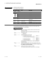
11 INSTRUCTIONS AND FUNCTIONS
11- 1 to 11-454
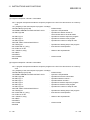
ABS (Returns the absolute value) ............................................................................................................... 11- 2
ASC (Returns the character code of the starting character) ...................................................................... 11- 3
ATN (Returns arc tangent)........................................................................................................................... 11- 4
AUTO (Automatically displays the line number) ......................................................................................... 11- 5
B@ (Reads and writes bit information)........................................................................................................ 11- 6
BEEP (The buzzer sounds) ......................................................................................................................... 11- 7
BIN$ (Returns a character string of the binary expression of an integer) .................................................. 11- 8
BSWAP (Swaps two values in byte units)................................................................................................... 11-10
CDBI (Converts a double precision real number to a 32-bit integer) ......................................................... 11-13
CDBL (Converts an integer or a single precision real number to a double precision real number).......... 11-15
CHAIN (Reads program or combine to execute) ........................................................................................ 11-17
CHR$ (Returns a character of the specified character code)..................................................................... 11-19
CIDB (Converts a 32-bit integer into a double precision real number) ...................................................... 11-20
CINT (Converts a single precision real number or a double precision real number into an integer) ........ 11-22
CISN (Converts a 32-bit integer into a single precision real number)........................................................ 11-24
CLEAR (Initializes all variables and sets up the memory area) ................................................................. 11-26
CLOSE (Terminates the I/O processing of a file)........................................................................................ 11-27
CLS (Clears the screen) .............................................................................................................................. 11-28
COM ON/OFF/STOP (Controls to enable, prohibit, and stop the interrupt from the
communication line) ............................................................................................................... 11-29
COMMON (Sets variable and others to be passed to the program to be read) ........................................ 11-30
CONSOLE (Sets the number of display lines of the console screen) ........................................................ 11-31
CONT (Resumes the program that was stopped) ...................................................................................... 11-32
COS (Returns a cosine value) ..................................................................................................................... 11-33
CSNG (Converts an integer or a double precision real number into a single precision real number) ...... 11-34
CSNI (Converts a single precision real number into a 32-bit integer) ........................................................ 11-35
CVD (Converts a character string, which was converted by the MKD$ function, back to
a double precision real number) ............................................................................................ 11-37
CVDMBF (Converts into the IEEE format double precision internal expression) ...................................... 11-38
CVI (Converts a character string, which was converted by the MKI$ function, back to an integer) ......... 11-39
CVS (Converts a character string, which was converted by the MKS$ function, back to
a single precision real number) .............................................................................................. 11-40
A-6
A-6
CVSMBF (Converts into the internal expression of a floating point real number that is used by
A2A and A3A) ......................................................................................................................... 11-41
(
DATA Specifies data to be read by READ) ............................................................................................... 11-43
DATE$ (Sets year, month, and day to the PLC CPU, and reads) ............................................................. 11-45
DEFDBL (Defines variables that start with a character of the specified range as the double
precision real number type).................................................................................................... 11-47
(
DEFFN Defines a user function) ................................................................................................................ 11-48
DEFINT (Defines variables that start with a character of the specified range as the integer type) .......... 11-50
DEFSNG (Defines variables that start with a character of the specified range as the single
precision real number type).................................................................................................... 11-51
(
DEFSTR Defines variables that start with a character of the specified range as the character type) ..... 11-52
DEF ZEVENT (Defines an event, and defines an event by bit device) ...................................................... 11-53
DELETE (Deletes the specified range of the program) .............................................................................. 11-56
DIM (Defines the array) ................................................................................................................................ 11-57
END (Terminates the execution of the program and brings to the input wait state or the idling state) ..... 11-59
EOF (End of a sequential file is detected) ................................................................................................... 11-60
ERASE (Deletes the array from memory) ................................................................................................... 11-61
ERL (Returns the line number where an error was detected) .................................................................... 11-62
ERR (Returns the error code of the detected error) ................................................................................... 11-63
ERROR (Generates the error of the specified error code) ......................................................................... 11-64
EXP (Returns the exponential function value) ............................................................................................ 11-65
FIELD (Assigns the area for the specified variable to the random file buffer) ........................................... 11-66
FILES (Displays the file name) .................................................................................................................... 11-67
FIX (Returns only the integer part after truncating the fractional part of the numeric value)..................... 11-68
FOR to NEXT (Executes a series of instructions for the specified number of times) ................................ 11-69
FORMAT (Initializes the file area of a memory card).................................................................................. 11-71
FRE (Returns the size of the unused area of memory in bytes) ................................................................ 11-73
GET (Reads one record from a random file to the random file buffer)....................................................... 11-74
GETMEM (Reads data from the buffer memory, common memory, and internal device ED) .................. 11-75
GOSUB RETURN (Branches to a subroutine) ........................................................................................... 11-79
GOTO (Branches to specified line).............................................................................................................. 11-81
HEX$ (Converts a decimal number to a hexadecimal character string) .................................................... 11-82
IF GOTO ELSE (Selects a branch destination according to the result of an expression) ......................... 11-83
IF THEN ELSE (Selects an instruction according to the result of the expression) .................................... 11-85
INKEY$ (Returns the character input from the keyboard) .......................................................................... 11-87
INPUT (Data entry from the keyboard)........................................................................................................ 11-89
IPUT$ (Returns a character string of the specified length after reading from the keyboard,
file and the communication port) ............................................................................................ 11-91
(
INPUT# Reads data from a sequential file) ............................................................................................... 11-94
INSTR (Returns a specified character string in the character string) ......................................................... 11-95
INT (Returns the integer value of the numeric expression) ........................................................................ 11-97
KEY (Defines a character string to a function key of the console) ............................................................. 11-99
KEYLIST (Displays the character string defined to the function key of the console) .............................. 11-100
KILL (Deletes a file) .................................................................................................................................... 11-101
A-7
A-7
LEFT$ (Extracts a character string of the number of characters specified from the left of
the character string) ............................................................................................................. 11-103
(
LEN Returns the number of characters of a character string)................................................................. 11-105
LET (Assigns the value of the expression to a variable) .......................................................................... 11-106
LFILES (Prints the filenames to the printer) .............................................................................................. 11-108
LINE INPUT (Stores the key input into a character string variable) ......................................................... 11-109
LINE INPUT# (Reads character from a sequential file into a character string variable) ......................... 11-111
LIST (Displays the program) ...................................................................................................................... 11-112
LLIST (The program will be printed to the printer) .................................................................................... 11-113
LOAD (Reads programs) ........................................................................................................................... 11-114
LOC (Returns the current logical location within a file) ............................................................................. 11-115
LOCATE (Specifies the display position on the console screen) ............................................................. 11-116
LOF (Returns the size of a file in record units).......................................................................................... 11-118
LOG (Returns a natural logarithm value) .................................................................................................. 11-119
LPRINT (Outputs data to the printer)......................................................................................................... 11-120
LPRINT USING (Outputs data in the specified format to the printer) ...................................................... 11-121
LSET (Moves data from memory to the random file buffer and stores left-justified) ............................... 11-122
MERGE (Merges programs in the memory and a read program) ............................................................ 11-123
MID$ (Part 1) (Replaces a section of a character string with another character string) .......................... 11-125
MID$ (Part 2) (Returns the partial character expression that begins with the specified position
in a character string) ............................................................................................................. 11-127
MKD$ (Converts a double-precision type numeric value into a character string).................................... 11-128
MKDMBF$ (Converts data of IEEE format internal expression to a character string that
can be converted to a numeric value using the CVD function) .......................................... 11-130
(
MKI$ Converts an integer type numeric value into a character string) ................................................... 11-131
MKS$ (Converts a single-precision type numeric value into a character string) ..................................... 11-132
MKSMBF$ (Converts data of floating point real numbers used by the A2A and A3A into
a character string that can be converted to a numeric value using the CVS function) ...... 11-133
(
NAME Changes file names) ..................................................................................................................... 11-135
NEW (Erases all programs in memory and initializes all variables) ......................................................... 11-137
OCT$ (Converts a numeric value into a character string variable in octal notation) ............................... 11-138
ON COM GOSUB (Branches to subroutine when an interrupt occurs from a communication line) ....... 11-140
ON ERROR GOTO (Branch to an error handling routine if an error occurs)........................................... 11-145
ON GOSUB (Branches to subroutine depending on the value of the specified expression) .................. 11-147
ON GOTO (Branches to specified line numbers depending on the value of the specified
expression) ........................................................................................................................... 11-149
(
OPEN Opens a file and enables it for input/output processing) .............................................................. 11-151
A-8
A-8
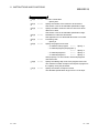
PCRD
.............................................................................................................................................. 11-153
PCRD - Processing Code 1 - (Reading device memory data) ................................................................. 11-155
PCRD - Processing Code 2 - (Reading device memory registered to be monitored by
the PCWT instruction) ..........................................................................................................11-158
PCRD - Processing Code 4 - (Reading extension file register data) ....................................................... 11-162
PCRD - Processing Code 5 - (Reading extension file registers registered to be monitored by
the PCWT instruction) ..........................................................................................................11-165
PCRD - Processing Code 7 - (Reading extension file register data by specifying sequential
addresses) ............................................................................................................................ 11-168
PCRD - Processing Code 8 - (Loading a sequence program) ................................................................. 11-173
PCRD - Processing Code 9 - (Loading a microcomputer program)......................................................... 11-177
PCRD - Processing Code 10 - (Reading comment data)......................................................................... 11-182
PCRD - Processing Code 11 - (Reading extension comment data) ........................................................ 11-185
PCRD - Processing Code 12 - (Reading a special function module’s buffer memory) ........................... 11-188
PCRD - Processing Code 13 - (Reading the type name of the PLC CPU) ............................................. 11-196
PCRD - Processing Code 14 - (Reading parameter data) ....................................................................... 11-199
PCRD - Processing Code 21 - (Reading network information) ................................................................ 11-204
PCRD - Processing Code 22 - (Reading routing parameters) ................................................................. 11-206
PCRD - Processing Code 513 - (Reading the type name of the Q/QnA series PLC CPU) .................... 11-208
PCRD - Processing Code 515 - (Reading device memory of the Q/QnA series PLC CPU) .................. 11-212
PCRD - Processing Code 516 - (Random read of device memory of the Q/QnA series PLC) .............. 11-218
PCRD - Processing Code 533 - (Reading the buffer memory of the intelligent function module /special
function module of the Q/QnA series PLC CPU) ................................................................ 11-229
PCWT
.............................................................................................................................................. 11-239
PCRD - Processing Code 1 - (Writing to device memory) ....................................................................... 11-241
PCWT - Processing Code 2 - (Monitor registration of device memory) ................................................... 11-245
PCWT - Processing Code 3 - (Random writing to device memory)......................................................... 11-250
PCWT - Processing Code 4 - (Writing to extension file registers) ........................................................... 11-254
PCWT - Processing Code 5 - (Monitor registration of extension file registers) ....................................... 11-257
PCWT - Processing Code 6 - (Random writing to extension file registers) ............................................. 11-261
PCWT - Processing Code 7 - (Writing data to extension file registers by specifying sequential
addresses) ............................................................................................................................ 11-264
PCWT - Processing Code 8 - (Writing a sequence program) .................................................................. 11-269
PCWT - Processing Code 9 - (Writing a microcomputer program).......................................................... 11-275
PCWT - Processing Code 10 - (Writing comment data)........................................................................... 11-280
PCWT - Processing Code 11 - (Writing extension comment data).......................................................... 11-283
PCWT - Processing Code 12 - (Writing to the special function module's buffer memory)...................... 11-286
PCWT - Processing Code 14 - (Writing parameter data) ......................................................................... 11-293
PCWT - Processing Code 15 - (Analyzing parameter data)..................................................................... 11-297
PCWT - Processing Code 16 - (Remote STOP of the PLC CPU) ........................................................... 11-299
PCWT - Processing Code 17 - (Remote RUN of the PLC CPU) ............................................................. 11-301
PCWT - Processing Code 20 - (Interrupting the PLC CPU)..................................................................... 11-303
PCWT - Processing Code 515 - (Writing data to the device memory of a Q/QnA series PLC CPU)..... 11-305
PCWT - Processing Code 516 - (Random data writing to the device memory of a Q/QnA series
PLC CPU) ............................................................................................................................. 11-310
A-9
A-9
PCWT - Processing Code 533 - (Writing data to the buffer memory of the intelligent function
module special function module of the Q/QnA series PLC CPU)....................................... 11-318
(
PRINT Displays data on the screen) ........................................................................................................ 11-327
PRINT USING (Displays a character string or numeric value in the specified format) ........................... 11-328
PRINT# (Writes data to a sequential file) .................................................................................................. 11-332
PRINT# USING (Writes data to a sequential file in the specified format) ................................................ 11-333
PUT (Writes one record from a random file buffer to a random file) ........................................................ 11-334
PUTMEM (Writes data to buffer memory, common memory, or internal device ED).............................. 11-335
RDSET (Reads one bit data from the specified bit) .................................................................................. 11-340
READ (Reads a value defined by the DATA instruction and assigns it to a variable) ............................. 11-342
REM (Provides comments) ........................................................................................................................ 11-343
RENUM (Reassigns line numbers of a program) ..................................................................................... 11-344
RESTORE (Specifies a data read with READ instruction) ....................................................................... 11-345
RESUME (Execution of the error handling routine is completed) ............................................................ 11-346
RIGHT$ (Extracts a character string consisting of the specified number of characters from
the right end of a character string and assigns it to a variable) .......................................... 11-347
(
RND Generates random numbers) .......................................................................................................... 11-348
ROT (Returns the bit-rotated value of the integer value data) ................................................................. 11-349
RSET (Moves data from memory to a random file buffer and stores right-justified) ............................... 11-351
RUN (1) (Starts the execution of the program) ......................................................................................... 11-352
RUN (2) (Executes after loading a program) ............................................................................................ 11-353
SAVE (Saves a program) .......................................................................................................................... 11-354
SEARCH (Searches for the specified value among the elements of the selected array
variable and returns the position of the element) ................................................................ 11-355
(
SGN Returns the sign of a value)............................................................................................................. 11-357
SHA (Returns the arithmetically shifted value of the integer data) ........................................................... 11-358
SHT (Returns the logically shifted value of the integer data) ................................................................... 11-360
SIN (Returns the sine)................................................................................................................................ 11-362
SPACE$ (Returns a null string of a specified length) ............................................................................... 11-363
SPC (Returns a specified number of blank spaces) ................................................................................. 11-364
SQR (Returns the square root of the specified value) .............................................................................. 11-365
STOP (Pauses the program execution or puts it in the stop status) ........................................................ 11-366
STR$ (Converts a value to a character string, assuming the value is given as a decimal number)....... 11-367
STRING$ (Returns the specified character for the specified number of times)....................................... 11-369
SYSTEM (Returns to system mode or the main menu screen) ............................................................... 11-371
SWAP (Swaps the values of two variables) .............................................................................................. 11-372
TAB (Moves the current character display position to the specified position) ......................................... 11-373
TAN (Returns the tangent) ......................................................................................................................... 11-374
TIME$ (Sets the time of the PLC CPU's clock and reads) ....................................................................... 11-375
TROFF (Resets the trace in a program) ................................................................................................... 11-377
TRON (Starts a trace in a program) .......................................................................................................... 11-378
VAL (Returns the value represented by a character string) ..................................................................... 11-379
W@ (Reads or writes word information) ................................................................................................... 11-381
WHILE WEND (These instructions are used repeatedly, while the specified condition holds)............... 11-383
WIDTH (Sets the width of data to be output to the printer)....................................................................... 11-385
WTSET (Writes 0 or 1 to the specified bit) ................................................................................................ 11-386
A - 10
A - 10
ZBAS (Returns the number of the BASIC task area in which the program currently being created) ..... 11-388
ZCLOSE (Closes a communication channel) ........................................................................................... 11-389
ZCNTL
.............................................................................................................................................. 11-390
ZCNTL - Processing Code 16 - (Specifying communication parameter)................................................. 11-392
ZCNTL - Processing Code 17 - (Reading communication parameters) .................................................. 11-392
ZCNTL - Processing Code 18 - (Specifying communication control parameters)................................... 11-394
ZCNTL - Processing Code 19 - (Reading communication control parameters) ...................................... 11-394
ZCNTL - Processing Code 22 - (Specifying break characters) ................................................................ 11-397
ZCNTL - Processing Code 23 - (Reading break characters) ................................................................... 11-397
ZCNTL - Processing Code 24 - (Specifying continuous break characters) ............................................. 11-399
ZCNTL - Processing Code 25 - (Reading continuous break characters) ................................................ 11-399
ZCNTL - Processing Code 32 - (Turning ON/OFF the RS and ER control signals)................................ 11-401
ZCNTL - Processing Code 33 - (Reading the ON/OFF status of the CS, DR, RS, ER and CD
control signals)...................................................................................................................... 11-403
ZCNTL - Processing Code 48 - (Specifying high impedance control) ..................................................... 11-405
ZCNTL - Processing Code 64 - (Reading causes of reception errors) .................................................... 11-406
ZCNTL - Processing Code 80 - (Reading the receive buffer size and the number of characters) ......... 11-408
ZCNTL - Processing Code 128 - (Reading the printer status) ................................................................. 11-409
ZCNTL - Processing Code 136 - (Outputting the initialization signal to the printer) ................................ 11-411
ZEVENT (Enables or disables event generation) ..................................................................................... 11-412
ZIDV (Specifies the data input device for the INPUT instruction, etc)..................................................... 11-413
ZLDV (Selects a communication port for a printer) ................................................................................... 11-414
ZMESSAGE (Defines a message port) ..................................................................................................... 11-415
ZMESSAGE CLOSE (Closes message ports).......................................................................................... 11-418
ZMESSAGE GET (Reads messages from message ports) ..................................................................... 11-419
ZMESSAGE KILL (Deletes the message ports) ....................................................................................... 11-421
ZMESSAGE OPEN (Opens a message port) ........................................................................................... 11-422
ZMESSAGE PUT (Writes messages to a message port) ........................................................................ 11-423
ZMOVE (Transfers data between valiables) ............................................................................................. 11-425
ZODV (Specifies the data output destination for the PRINT instruction, etc) .......................................... 11-430
ZOPEN (Opens a communication channel) .............................................................................................. 11-431
ZRECEIVE (Receives data from a communication channel) ................................................................... 11-433
ZRELEASE (Allows other programs to use a resource to which a resource number is assigned) ........ 11-439
ZRESERVE (Prohibits other programs from using a resource to which a resource number is
assigned) .............................................................................................................................. 11-440
ZSEND (Sends data from a communication channel) .............................................................................. 11-442
ZSIGNAL (Generates the specified event)................................................................................................ 11-448
ZSTART (Starts up the specified program) ............................................................................................... 11-449
ZURGENCY (Changes the priority of a program)..................................................................................... 11-451
ZWAIT DELAY (Pauses the program execution until the specified time has elapsed) ........................... 11-452
ZWAIT EVENT (Pauses the program execution until the specified event is generated) ........................ 11-453
A - 11
A - 11
APPENDIX
App- 1 to App-44
Appendix 1
Appendix
Appendix
Appendix
Appendix
Appendix
Appendix
Appendix 2
Appendix 3
File Name..............................................................................................................................App- 1
1.1 Drive Number.................................................................................................................App- 2
1.2 System Name ................................................................................................................App- 2
1.3 File Name.......................................................................................................................App- 3
1.4 Wild Cards......................................................................................................................App- 4
1.5 Precautions when Using Wild Cards.............................................................................App- 5
1.6 The Efficient Way to Assign a File Name .....................................................................App- 5
Precautions on Interrupt Processing....................................................................................App- 6
Instructions and Functions that Switch Between Programs to be Executed in
Multitasking...........................................................................................................................App- 7
Appendix 4 Code Table ...........................................................................................................................App- 8
Appendix 4.1 Character Code Table ...................................................................................................App- 8
Appendix 4.2 List of Control Keys........................................................................................................App- 9
Appendix 4.3 Control Codes for Screen Display when Using the General-Purpose Console ..........App-10
Appendix 4.4 List of Error Messages and Error Codes.......................................................................App-11
Appendix 4.4.1 Error message list...................................................................................................App-12
Appendix 4.4.2 System error code table .........................................................................................App-16
Appendix 5 How to Obtain Trigonometric Functions not Available in AD51H-BASIC...........................App-23
Appendix 6 Reserved Words...................................................................................................................App-24
Appendix 7 Details of Communication Control .......................................................................................App-26
Appendix 7.1 DC1/DC3 Control...........................................................................................................App-26
Appendix 7.1.1 DC1/DC3 transmission control enabled.................................................................App-26
Appendix 7.1.2 DC1/DC3 reception control enabled ......................................................................App-27
Appendix 7.2 Control by Signals......................................................................................................App-28
Appendix 7.2.1 ER (DTR) control enabled ......................................................................................App-28
Appendix 7.2.2 RS (RTS) control enabled ......................................................................................App-30
Appendix 7.2.3 DR (DSR) control enabled......................................................................................App-32
Appendix 7.2.4 CS (CTS) control enabled ......................................................................................App-33
Appendix 7.2.5 How to connect the communication module to an external device and
precautions on specifying control by signals.........................................................App-34
Appendix 7.3 Break Control .................................................................................................................App-36
Appendix 7.3.1 Break character specifying side .............................................................................App-36
Appendix 7.3.2 Flow of received data when a break character is specified...................................App-37
Appendix 7.4 Data Flow When an Error Occurs During Data Reception...........................................App-38
Appendix 7.4.1 Data flow when a transmission error occurs..........................................................App-38
Appendix 7.4.2 Data flow when a receive buffer full error occurs ..................................................App-41
Appendix 7.5 How to Clear Reception Data Stored in the Receive Buffer ........................................App-42
Appendix 7.6 Sending or Receiving Character Data of 256 Bytes or More .......................................App-42
Appendix 8 Starting Address of Each Intelligent Function Module/ Special Function Module..............App-43
A - 12
A - 12
How to use this manual
• Please read Chapter 1 through Chapter 11 and the Appendix if the manual should be used with Interpreter
BASIC.
• Please read the AD51H-BASIC Programming Manual (Debug and Compile) and understand the restrictions
of the compiler if the manual should be used with Compiler BASIC. Then proceed to read Chapter 1
through Chapter 11 and the Appendix.
Regarding Compiler BASIC
• Please be aware that there are many detailed restrictions for each instruction when using Compiler BASIC.
See the AD51H-BASIC Programming Manual (Debug and Compile) for details on these restrictions.
• An assembler and a linker is required to compile programs. These are not included in the SW1IVDAD51HP-E software package and must be purchased separately.
Recommended Products
• IBM/AT Compatible Personal Computer
Turbo Assembler Ver 5.0
For Turbo Assembler, contact Borland Software Corporation.
• MS-DOS is used for the Compiler BASIC. The user must have adequate knowledge about MS-DOS to use
it.
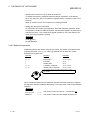
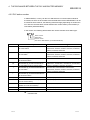
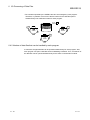
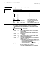
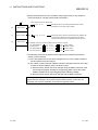
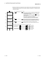
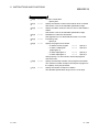
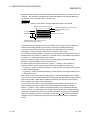
About Module Names
The module model names are abbreviated as follows in this manual.
AD51H-S3
A1SD51S
QD51
QD51-R24
QD51 (-R24)
Communication Module
A - 13
•••••
•••••
•••••
•••••
•••••
•••••
Refers to operations only for the AD51H-S3.
Refers to operations only for the A1SD51S.
Refers to operations only for the QD51.
Refers to operations only for the QD51-R24.
Refers to common items for both the QD51 and the QD51-R24.
Refers to common items for all modules.
A - 13
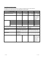
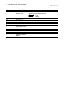
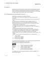
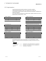
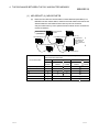
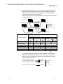
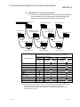
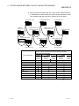
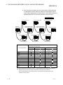
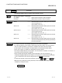
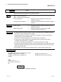
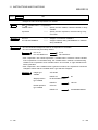
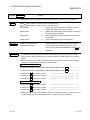
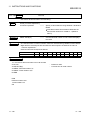
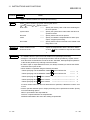
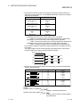
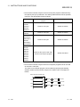
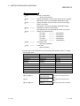
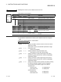
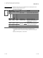
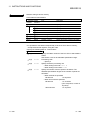
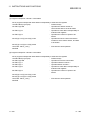
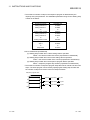
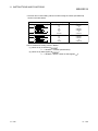
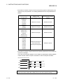
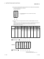
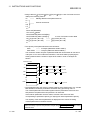
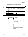
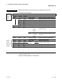
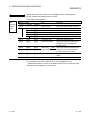
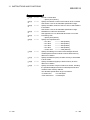
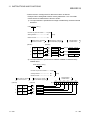
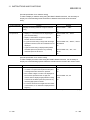
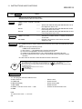
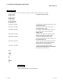
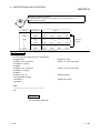
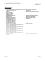
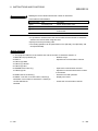
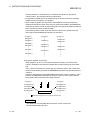
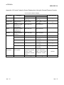
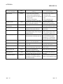
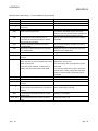
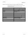
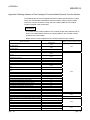
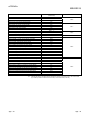
About differences between modules
Descriptions in this manual uses AD51H-S3, A1SD51S and QD51(-R24) as module examples.
The differences are shown below since the settings differ for each module.
QD51
QD51-R24
A1SD51S
AD51H-S3
The number of tasks
2
2
2
8
General-purpose input/output
Input
Output : 23 points
Output : 23 points
Output : 23 points
Output : 17 points
The number of I/O points occupied
32 points
32 points
32 points
48 points
: 26 points
Input
: 26 points
Input
: 27 points
Input
: 27 points
(first 16 points as
vacant, second
32 points as
special)
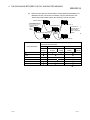
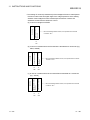
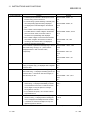
Interface
CH1(RS-232)
CH2(RS-232)
CH3(RS-422/485)
―
―
CH4(parallel)
―
―
―
Memory card
―
―
―
(Number of
loadable cards: 2)
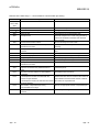
Transmission rate
300, 600, 1200, 2400, 4800, 9600,
300, 600, 1200, 2400, 4800, 9600,
14400, 19200, 28800, 38400 bps
19200 bps
Character length
7, 8
5, 6, 7, 8
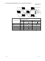
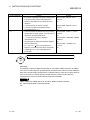
Console setting
Set in the "Switch setting for I/O and
Set at the mode switch2 of the DIP
intelligent function module" screen of
switch on the communication module.
Mode switching
GX Developer.
Set in the "Switch setting for I/O and
intelligent function module" screen of
GX Developer.
Set at the mode switch1 of the rotary
switch on the communication module.
Execution time switching
Unsupported
Unsupported
Unsupported
Supported
(Set at the mode
switch3 of the DIP
switch on the
AD51H-S3
communication
module.)
Refer to the user’s manual for each communication module for details.
A - 14
A - 14
1 OVERVIEW
MELSEC-Q
1 OVERVIEW
This programming manual describes how to use instructions and functions of the
programming language "AD51H-BASIC" used with the communication module.
Please refer to the following manuals as necessary when using AD51H-BASIC.
• Intelligent communication module type AD51H-S3 User's Manual
• Type A1SD51S Intelligent communication module User's Manual
• Q Corresponding Intelligent Communication Module User's Manual
• AD51H-BASIC Programming Manual (Debug and Compile)
• AD51H-BASIC Package type SW1IVD-AD51HP-E Operating Manual
1-1
:
:
:
:
:
(IB(NA) - 66401)
(IB(NA) - 66551)
(SH(NA) - 080089)
(SH(NA) - 080091)
(IB(NA) - 66698)
1-1
1
1 OVERVIEW
MELSEC-Q
1.1 Features
1
The following are features of AD51H-BASIC.
(1) Both interpreter-type BASIC and compiler-type BASIC languages
can be employed.
This allows easy creation of system control programs and programs that perform
data linking with a computer without being aware of the complicated internal
structure of the module; it is easy to use even for beginners.
The execution speed can be made faster by compiling already created programs.
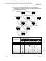
(2) Multiple programs can be executed simultaneously by means of
multitask processing.
The communication module supports multitask processing. Because of this, up to
8 BASIC programs can be executed simultaneously on the AD51H-S3, and up to
2 BASIC programs can be executed simultaneously on the A1SD51S/QD51 (R24). In such cases, the communication module sequentially switches the
execution of each program, so it appears to the user as if the multiple programs
are running simultaneously.
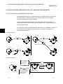
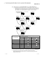
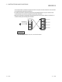
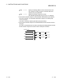
(3) Data can be communicated between programs via message ports
and communication module internal devices.
When multiple programs are executed simultaneously using the multitask
processing function, data can be communicated using the following means.
1) Message ports • • • • • • • • • • • • • • • • • • • • • • • 1 to n data communication
2) Communication module internal devices • • • • • 1 to n data communication
3) Shared memory • • • • • • • • • • • • • • • • • • • • • • • 1 to n data communication
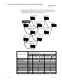
(4) Execution can be synchronized between programs via events.
When multiple programs are executed simultaneously using the multitask
processing function, it is possible to synchronize their executions. This is
achieved by making programs wait for an event using the ZWAIT EVENT
instruction and generating an event by the ZSIGNAL instruction.
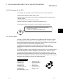
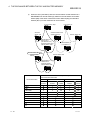
(5) Instructions for data link with external devices have been unified.
Data link with the PLC CPU of the same station as the communication module or
other PLC CPUs via MELSECNET can be performed using the PCRD/PCWT
instructions. The data link between the various interfaces of the communication
module and external devices is performed using the ZRECEIVE/ZSEND
instructions.
In this way, by creating a single subroutine that performs data link, it is possible
to share the arguments of each instruction by passing them to variables in that
subroutine.
1-2
1-2
1 OVERVIEW
MELSEC-Q
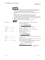
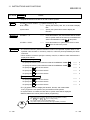
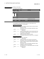
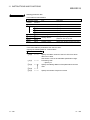
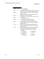
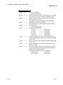
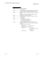
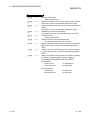
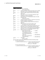
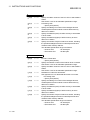
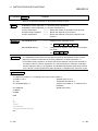
1.2 Symbols Used in This Manual
This manual uses the following symbols (used especially within Format ) for
descriptive purposes.
The symbols and their meanings are described in the following. Be sure to understand
them fully before starting to create programs. Note that the symbols shown below
should not be entered when actually entering the instructions and arguments related to
the description sections that use these symbols. Doing so will result in a syntax error.
Other symbols and characters have special meanings. Use them according to their
descriptions.
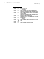
[ ] (Square brackets)
{ } (brackets)
< >
| (vertical line)
H
Ctrl +
Enter
1-3
: [ ] indicates that the arguments inside them are
optional.
: { } indicates that the arguments inside them are
optional or can be repeated.
: < > indicates that the single item inside should be
entered (specified) by the user.
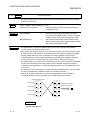
: Indicates that one of the two or more items
separated by pipe symbols must be chosen and
entered. When the range of options is hard to see, it
is underlined.
: Indicates a place where at least one space must be
entered, or a single space.
: Indicates that the alphanumeric string immediately
before it is an integer value expressed in
hexadecimal format.
: Indicates a key operation where the key is pressed
while at the same time holding the control key
pressed.
: Indicates that the enter key should be pressed.
1-3
2 THE BASICS OF AD51H-BASIC
MELSEC-Q
2 THE BASICS OF AD51H-BASIC
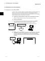
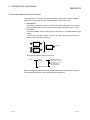
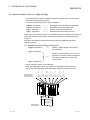
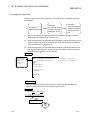
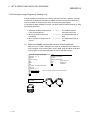
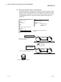
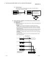
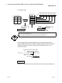
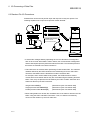
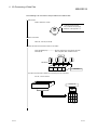
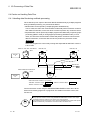
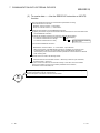
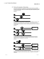
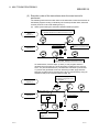
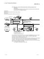
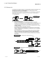
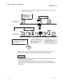
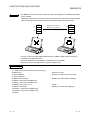
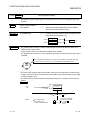
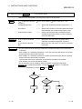
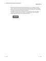
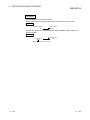
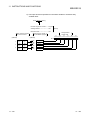
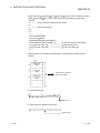
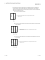
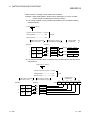
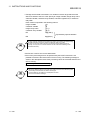
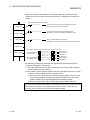
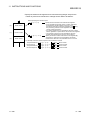
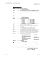
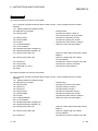
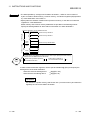
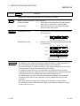
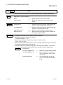
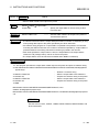
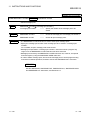
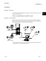
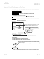
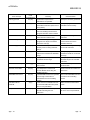
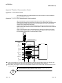
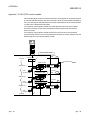
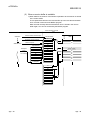
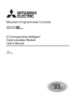
2.1 Preparation to Use AD51H-BASIC
In order to edit or execute a program using AD51H-BASIC (hereinafter referred to as
BASIC), it is necessary to change the mode of the communication module to
programming mode, then connect the console, and start up BASIC. The procedures
and the relevant reference manuals are shown below.
2
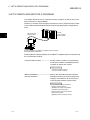
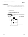
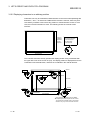
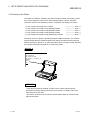
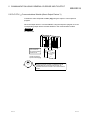
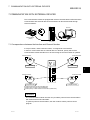
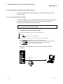
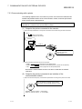
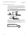
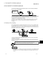
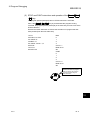
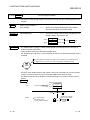
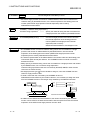
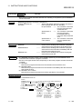
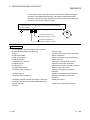
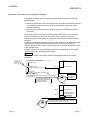
(1) Setting the communication module and connecting the console.
Perform settings and connections for each communication module.
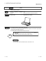
(2) Console preparation
Carry out the online programming items according to the Type SW IVDAD51HP/SW NX-AD51HP Software Package Operation Manual.
This is not necessary
when using a general-purpose
console.
IBM/AT Compatible Personal Computer
SW1IVD-AD51HP-E
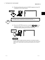
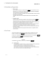
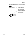
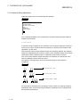
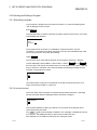
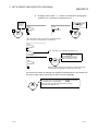
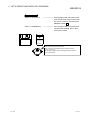
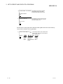
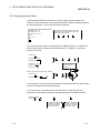
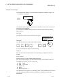
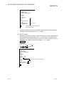
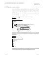
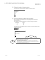
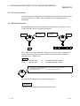
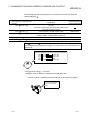
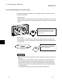
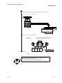
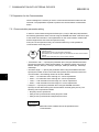
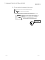
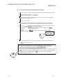
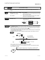
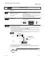
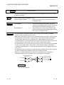
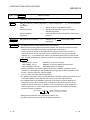
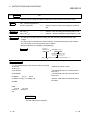
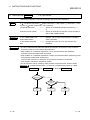
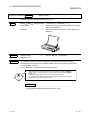
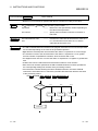
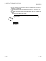
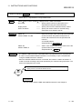
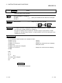
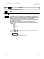
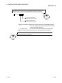
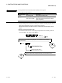
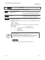
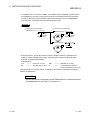
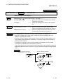
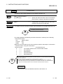
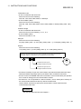
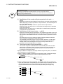
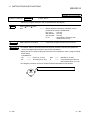
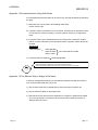
(3) Editing and running BASIC programs can be started by using the
START instruction in the system mode of the communication
module, according to the user’s manual for each communication
module.
E xe c u te
the START
instruction.
2-1
S>START
,
En te r
2-1
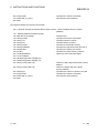
2 THE BASICS OF AD51H-BASIC
MELSEC-Q
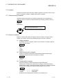
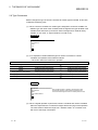
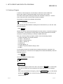
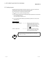
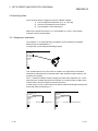
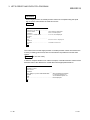
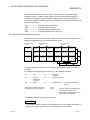
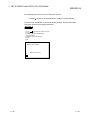
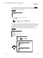
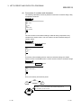
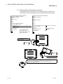
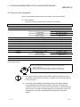
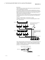
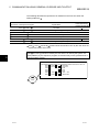
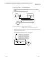
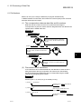
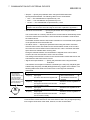
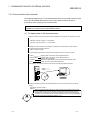
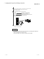
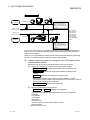
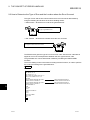
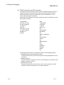
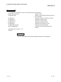
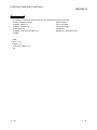
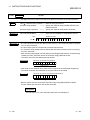
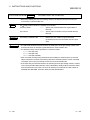
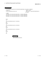
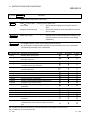
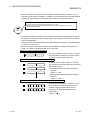
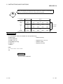
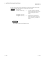
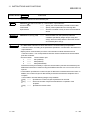
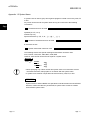
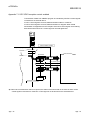
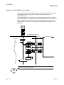
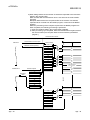
(4) This allows editing and execution of BASIC programs and an ‘OK’
is displayed on the console screen.
BASIC can now
be used.
AD51H-BASIC ON-LINE PROGRAMING Ver X.X
OK
2
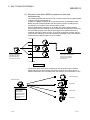
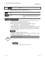
Using the START instruction in system mode starts up BASIC and changes the mode of the
communication module into a mode referred to as "online programming mode."
This mode allows creation of a BASIC program and execution of a single-task program.
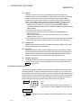
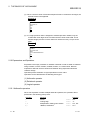
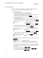
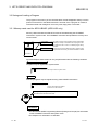
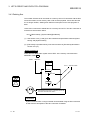
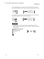
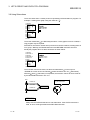
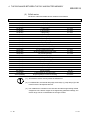
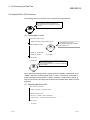
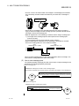
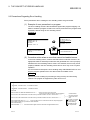
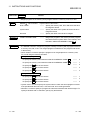
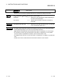
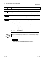
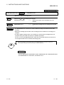
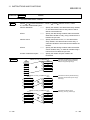
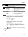
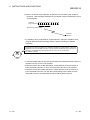
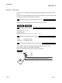
(5) Execute the SYSTEM instruction or press the Ctrl + D keys to
change the mode of the communication module back to system
mode after finishing editing and execution with BASIC.
Return to
system mode.
S>
REMARK
• In order to perform multitask operation of programs, it is necessary to perform
multitask settings and specify the execution in system mode of the communication
module. See the AD51H-BASIC Programming Manual (Debug and Compile) for
details.
2-2
2-2
2 THE BASICS OF AD51H-BASIC
MELSEC-Q
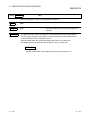
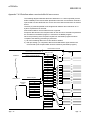
Note
There are two modes for executing BASIC programs in the communication module.
• Programming mode (online programming mode)
In this mode, BASIC programs can be executed online, and only the BASIC
program being edited can be executed.
It is not possible to perform multitask execution of BASIC programs while in
programming mode.
This manual describes examples of programming and execution in
programming mode, with the exception of multitask instructions.
• Run mode
This mode allows multitask execution of BASIC programs that use multitask
instructions.
It is not possible to create or edit BASIC programs in run mode.
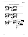
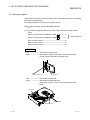
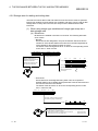
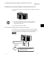
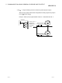
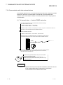
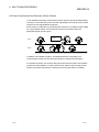
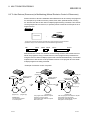
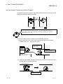
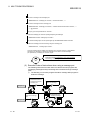
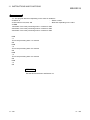
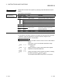
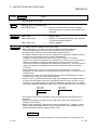
Changing between programming mode and run mode of the communication module
is performed by the methods shown below.
• AD51H-S3, A1SD51S
•••••
• QD51 (-R24)
•••••
Use the rotary switch of the main module
(Mode setting switch)
"Switch setting for I/O and intelligent function
module" screen of GX Developer
See the user’s manual for each communication module for detailed descriptions of
each mode and changing between them.
2-3
2-3
2 THE BASICS OF AD51H-BASIC
MELSEC-Q
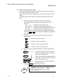
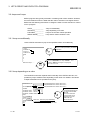
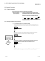
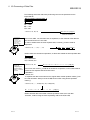
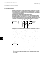
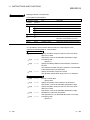
2.2 Direct Mode and Program Mode
• Direct mode
When a BASIC instruction is entered and the Enter key is pressed while “OK” is
displayed on the console screen, BASIC will execute the instruction immediately.
This is referred to as execution in direct mode.
The results of the operation executed in direct mode will remain in memory, but the
instruction line will be cleared.
All BASIC instructions with the exception of DEF FN can be executed in direct
mode.
• Program mode
Entering a BASIC instruction preceded by a line number and pressing Enter will
store the instruction in the memory of the communication module. Lines are
comprised of line numbers and BASIC instructions, and a group of more than one
line is referred to as a BASIC program (or simply, a program).
A program is comprised of statements that specify a series of operations that the
computer performs. Designing and testing a program is referred to as
programming. Programs stored in memory can be executed by entering the RUN
instruction of BASIC.
This execution is referred to as program mode execution, as opposed to direct
mode execution.
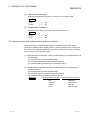
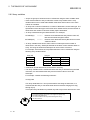
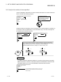
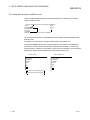
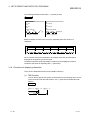
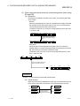
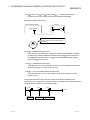
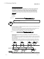
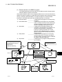
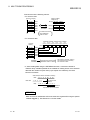
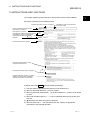
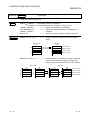
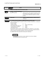
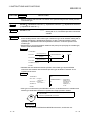
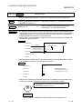
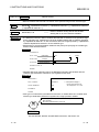
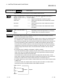
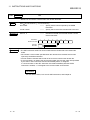
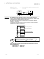
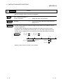
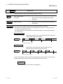
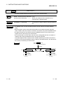
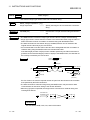
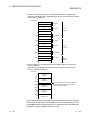
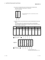
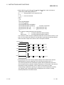
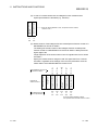
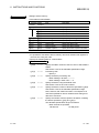
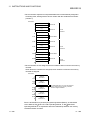
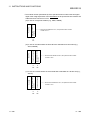
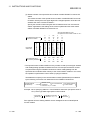
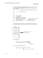
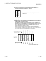
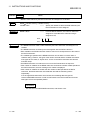
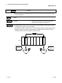
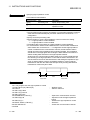
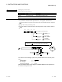
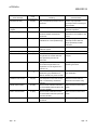
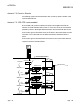
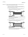
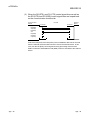
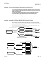
2.3 Line Format
Lines are the smallest components of a program and are comprised of one <line
number>, a sentence, and a Return symbol that indicates the end of the line.
A sentence is a collection of <statements> that make sense as an instruction. ( Return
is entered by pressing the Enter key while editing the program.)
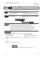
The line format is as follows:
Sentence
<Line Number>
[<Label:>] <Statement> {:<Statement> } Return
(1) Line Number
<Line Numbers> are written from the 1st column of the line and are represented
by whole numbers between 1 and 65529 (decimal constant).
The line numbers are placed in ascending order within the program.
Line numbers act as indices for controlling program execution, and at the same
time, as line search indices when editing the program.
2-4
2-4
2 THE BASICS OF AD51H-BASIC
MELSEC-Q
(2) Labels
<Labels> are terms in lines that are specified as branch destinations for
instructions such as GOTO, GOSUB, and RESTORE, or lines that are specified
as the next data to be read. They are placed next to line numbers. When
specifying a line that includes <Label> in instructions such as the ones listed
above, it is possible to specify the line by the label instead of the line number.
• Labels are character strings that begin with an asterisk ( ). A label is
expressed as a maximum of 15 alphanumeric characters and periods,
excluding the asterisk, starting with an alphabetic character. All labels must be
distinguishable.
• Reserved words cannot be used as labels.
• The label name referred to (label name called) must be placed at the
beginning of the line.
• When a label is followed by an instruction within one line, they must be
separated using a colon (:).
• If the same label name is defined in several places, the label with the smallest
line number will always be referenced and an error will not be generated.
(3) Statements
<Statements> are instructions that are written following the BASIC syntax and
form the smallest element of a sentence.
(4) Colons (:)
Colons are symbols used to separate statements when one sentence contains
multiple statements. Sentences comprised of one statement are referred to as
simple sentences. Sentences comprised of multiple statements separated by
colons (:) are referred to as complex sentences (multi-statements).
(5) Length of one line
The length of one line must be less than 254 characters, including line number
and spaces. One program line is considered to end at the location where the
Enter key is pressed.
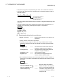
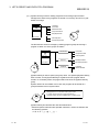
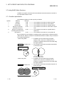
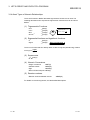
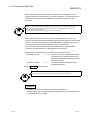
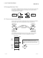
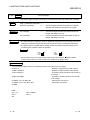
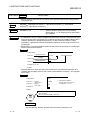
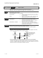
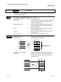
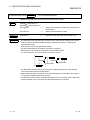
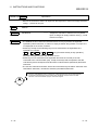
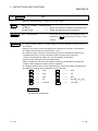
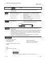
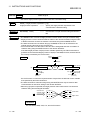
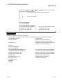
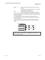
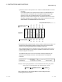
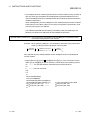
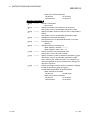
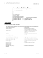
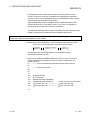
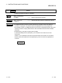
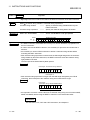
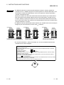
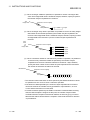
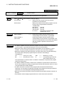
2.4 Spaces and Keywords
The names of the BASIC instructions and functions are keywords that have special
meanings in BASIC. A space (Character 20h shown in Appendix 4.1) should not be
entered within these keywords. Moreover, keywords, variables, arrays, constants, and
logical operators must be separated using spaces, parentheses, numerical operators,
or other symbols allowed by the syntax rules. Spaces can be used freely in all other
places, and will be ignored no matter where in the sentence they appear.
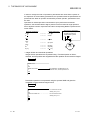
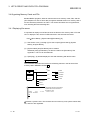
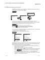
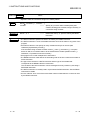
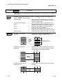
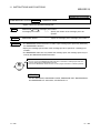
Example
P R I N T
A = B + C
A=B AND C
A=BANDC
Error
OK
The logical product of B and C will be entered in A
The contents of variable BANDC will be entered in A
REMARK
The Enter key (Enter key) will be referred to differently depending on the console
used.
2-5
2-5
2 THE BASICS OF AD51H-BASIC
MELSEC-Q
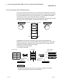
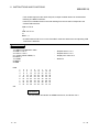
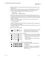
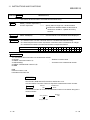
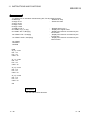
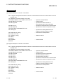
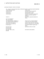
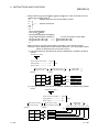
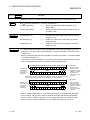
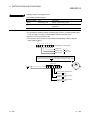
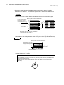
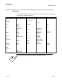
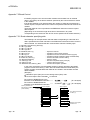
2.5 Characters Used in BASIC
The following characters are used in BASIC.
• Uppercase alphabet
• Lowercase alphabet
• Numbers
• Special characters
ABCDEFGHIJKLMNOPQRSTUVWXYZ
abcdefghijklmnopqrstuvwxyz
0123456789
(Space) ! ” # $ % & ‘ ( ) * + - , . / : ; < > = ? @ [ ] ¥ ^ { } | –
See Appendix 4.1, Character Code Table for the codes for alphabets, numbers and
special character.
The program instructions are entered using uppercase or lowercase alphabet
characters and symbols that are specified in the syntax. Other characters cannot be
used as character data.
The instructions are treated in the exact same manner whether entered in uppercase
or lowercase alphabet characters, and all instructions entered in lowercase will be
converted to uppercase and stored in a memory.
However, the character data (notation characters or file names enclosed in “ ”) will be
stored exactly the way it is coded.
2-6
2-6
2 THE BASICS OF AD51H-BASIC
MELSEC-Q
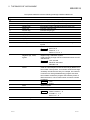
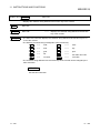
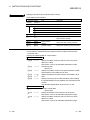
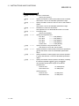
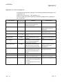
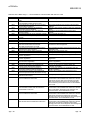
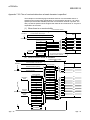
The special characters have the following meanings in BASIC statements.
Special Character
Name
!
“
#
$
%
&
‘
(
)
*
+
Space
Exclamation
Double quotation mark
Number sign
Dollar sign
Percent sign
Ampersand
Apostrophe
Left parenthesis
Right parenthesis
Asterisk
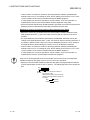
Plus sign
,
Comma
-
Negative sign, minus,
hyphen
.
Period
/
:
;
Slash
Colon
Semicolon
<
Less-than sign
2-7
Meaning
Used to separate instructions and parameters.
Indicates single-precision type.
Symbols for enclosing a character string.
File number symbol, indicates double-precision type.
Indicates character type.
Indicates integer type.
Specifies character format.
Comment delimiter
Multiplication symbol
Positive symbol, addition symbol, character string addition
symbol
Delimiter
INPUT A, B
Example
PRINT X, Y, Z
DATA 10, 13, 91, 4
Negative sign, subtraction symbol.
Used to specify a range of lines in instructions such as LIST
and DELETE.
Example LIST 100-300
DELETE 1000-3000
DEFDBL A-H
Used as a decimal point as well as internally by BASIC as a
line number control pointer. Line number values that change
constantly are stored in this way, for example, line numbers
in which errors were generated during program execution,
line numbers at which the program was halted by STOP or
END instructions, or line numbers when a new line number
is inserted.
Example LIST.
AUTO.
Division symbol.
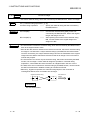
Multi-statement delimiter
Delimiter
Example PRINT “Answer=” ; A
A PRINT X ; Y ; Z
INPUT “A=” ; A
2-7
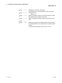
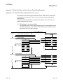
2 THE BASICS OF AD51H-BASIC
=
>
?
Equal sign
Greater-than sign
Question mark
@
Commercial at
Left bracket
Yen sign
Right bracket
Accent circonflexe
(upward arrow head)
Underscore
Accent grave
Left square bracket
Vertical line
Right square bracket
High bar
¥
^
_
[
|
]
¯
2-8
MELSEC-Q
Substitution for the PRINT instruction
? A, B
Example
?FRE(0)
?TIME$
Integer division symbol
Power symbol
2-8
2 THE BASICS OF AD51H-BASIC
MELSEC-Q
2.6 What are Instructions and Functions?
Only instructions or functions that follow the BASIC syntax can be written in BASIC
statements. The section describes what instructions and functions are.
• Instructions
Each BASIC instruction instructs a certain processing to take place. For example,
when the PRINT instruction is used, characters will be displayed on the screen.
• Functions
Functions in BASIC return a single value in response to 1 or multiple arbitrary input
values.
Functions can only return values. Therefore, in order to use the results, they are
used in conjunction with instructions.
X
Function
A
Instruction
Processing
X
Y
Function
A
Z
There are the following types of functions.
Function
Built-in
functions
User-defined functions
Numerical functions
Character functions
Character functions
for input/output
Special functions
Built-in functions are functions already provided with BASIC. User-defined functions
are functions defined by the user using the DEFFN instruction.
2-9
2-9
2 THE BASICS OF AD51H-BASIC
MELSEC-Q
2.7 Constants
Constants are fixed values used when a BASIC program is executed. There are two
types of constants: character constants and numeric constants.
2.7.1 Character string constants
Character string constants are any character strings that can be contained in a
character set up to a maximum of 255 characters enclosed by quotation marks (“).
Example
“HELLO”
“$25,000.00”
A character string that has a character length of 0 is
referred to as an empty character string.
In this manual, empty character strings are denoted by " ".
2.7.2 Numeric constants
Numeric constants are positive or negative numbers. Numeric constants cannot
contain any commas. There are the following 5 types of numeric constants.
(1) Integer constants
All integers between –32768 to +32767, with or without a % symbol. Decimal
points cannot be added.
Example
100
+123
-32768
32767%
(2) Fixed decimal point constants
Positive or negative real numbers (numbers that include decimal points),
including all integers that are not included in (1) above.
Example
100.0
-123.21
(3) Floating-point constants
Positive or negative numbers expressed in exponential format.
Floating-point constants are comprised of an integer or fixed decimal point
number (base number), followed by the letter E, and then an integer (exponent).
Floating-point constants can express values between 10-38 to 10+38.
Example
235.988E-7
• • • • • 0.0000235988
2359E6
• • • • • 2359000000
(Double-precision floating-point constants use D instead of E.)
2 - 10
2 - 10
2 THE BASICS OF AD51H-BASIC
MELSEC-Q
(4) Hexadecimal Constants
A hexadecimal number (0 through 9, A through F) is preceded by &H.
Example
&H76
&H32F
•••••
•••••
118
815
(5) Octadecimal Constants
An octadecimal number (0 through 7) is preceded by &0 or &.
Example
&0347
&1234
•••••
•••••
231
668
2.7.3 Single-precision and double-precision numeric constants
Fixed decimal point constants and floating-point constants can be either single
precision or double precision. Single-precision constants are stored in a memory with
an accuracy of 7 significant digits. Double-precision constants are stored in a memory
with an accuracy of 16 significant digits.
(1) Single-precision constants are numeric constants that can be categorized into one
of the following:
(a) Constants with 7 or less significant digits
(b) Constants expressed in exponential format using E
(c) Constants that are followed by an exclamation mark (!)
(2) Double-precision constants are numeric constants that can be categorized into
one of the following:
(a) Constants with 8 or more significant digits
(b) Constants expressed in exponential format using D
(c) Constants that are followed by a number sign (#)
Example
Single-precision constants
46.8
-7.09E-06
3489.0
22.5!
2 - 11
Double-precision constants
345692811
-1.09432D-06
3489.0#
7654321.1234
2 - 11
2 THE BASICS OF AD51H-BASIC
MELSEC-Q
2.8 Variables
Variables are names that are used to represent values used within BASIC programs.
Values of variables can be defined by the programmer or assigned as calculation
results. The values of numeric variables are 0 and values of character string variables
are empty character strings until their proper values are defined.
2.8.1 Variable names and type declaration characters
Variable names are subject to the following restrictions:
• The length of variable names within BASIC is restricted to a maximum of 15
characters.
• Variable names must be comprised of alphanumeric characters. Periods are also
valid.
• The first character of a variable name must be an alphabet character.
• Special characters (%, !, #, $) may be used as a type declaration character.
• Reserved words cannot be used for variable names, but reserved words may be
used as a portion of a variable name.
Reserved words include all instruction, function, and operator names.
• If a variable name begins with FN, it is considered to be a call to a user-defined
function.
• Variables represent either numeric values or character strings.
• The last character of a character string variable name must be a dollar sign ($).
For example, in A$=”SALESREPORT”, the dollar sign is a variable declaration
character, and “declares” that the variable represents a character string.
• Numeric variable names can be declared as single-precision, double-precision, or as
integers.
• There are the following types of declaration characters for variable names.
%
!
#
$
Integer variables
Single-precision variables
Double-precision variables
Character string variables
If a declaration character is omitted in a numeric variable name, it is assumed that the
variable represents a single-precision numeric value.
The following are some examples of variable names.
Example
PI#
MINIMUM!
LIMIT%
N$
ABC
•••••
•••••
•••••
•••••
•••••
Declares a double-precision variable.
Declares a single-precision variable.
Declares an integer variable.
Declares a character string variable.
Declares a single-precision variable.
The variable type can also be declared using DEFINT, DEFSTR, DEFSNG, and
DEFDBL within programs.
2 - 12
2 - 12
2 THE BASICS OF AD51H-BASIC
MELSEC-Q
2.8.2 Array variables
• Arrays are groups of values that can be referenced using the same variable name.
• Each element within an array is referred to via the array variable name. Array
variable names can be used within BASIC instructions and functions in the same
manner as variables.
• An array has a number of elements, a number of dimensions, and a value type. The
specification of the value type is the same as for variable names, but the number of
dimensions and number of elements usually require declaration.
• An array is declared using the DIM instruction. For example,
10 DIM A$(3)
Declares a one-dimensional array with the name A$
that uses character strings as values.
20 DIM B(3,2)
••••••
Declares a two-dimensional array B that uses numeric
values as values.
• An array variable name has the same number of subscripts as the number of
dimensions in the array. Subscripts indicate the location of each element within an
array. The range of values that subscripts can have is from 0 to 32767.
For example, each element of arrays A$ and B above can be referenced using the
following array variable names.
Array A$
A$(0)
A$(1)
A$(2)
A$(3)
••••••
Array B
B(0,0)
B(1,0)
B(2,0)
B(3,0)
B(0,1)
B(1,1)
B(2,1)
B(3,1)
B(0,2)
B(1,2)
B(2,2)
B(3,2)
• A maximum of 255 dimensions can be used in one array.
• If an array variable name is referenced before the array is declared using the DIM
instruction, it is assumed that the array has a maximum value of 10 for the
subscripts.
For example, consider the following instruction:
30 C(3)=200
If an array declaration for C is not present before executing the instruction, it is
assumed that the array is one-dimensional and has elements ranging from C(0)
through C(10).
This implicit array declaration is possible only with arrays of two dimensions or less.
Some AD51H-BASIC instructions do not support the implicit array
declaration described above.
It is recommended to use arrays after declaring them using
the DIM instruction.
2 - 13
2 - 13
2 THE BASICS OF AD51H-BASIC
MELSEC-Q
2.8.3 Special variables (How to use B@ and W@)
• These variables are used to read/write from/to each device of the communication
module from within BASIC programs.
• There are the following 4 types of special variables.
B@ (EM, expression)
W@ (ED, expression)
B@ (X, expression)
W@ (Y, expression)
•••••
•••••
•••••
•••••
Read/write from/to the extension relays EM.
Read/write from/to the registers ED.
Write to general-purpose inputs X.
Read from general-purpose outputs Y.
Refer to the user’s manual for each communication module for details on the extension
relays EM, extension registers ED, general-purpose inputs X, and general-purpose
outputs Y.
Note that it is possible to read and write to/from the special EM and special ED
extension devices.
(1) Reading from and writing to bit devices
B@(EM, expression)
•••••
Specify a value between 0 and 1023 for
the expression.
B@(X, expression)
Specify a value between 0 and 1FH for the
expression. Since this must be specified in
hexadecimal, place ‘&H’ in front of the
numeric value.
•••••
B@(Y, expression)
• Specify a device number in the expression.
When general-purpose inputs X or outputs Y are specified, values between 0
and1FH are used regardless of the input/output numbers of the entire system.
The input/output
numbers as seen
from the PLC CPU
A
X
41
A
X
41
A
X
41
A
Y
41
A
Y
41
A
Y
41
(32 points) (32 points) (48 points) (32 points) (32 points) (32 points) (32 points)
0 to 1F • 20 to 3F • 40 to 6F • 70 to 8F • 90 to AF • B0 to CF • D0 to EF
40
to 4F
?
?
Value specified
in the expression
2 - 14
AD
51
H
50 to 6F
General-purpose
inputs/outputs
X, Y
0 to 1F
2 - 14
2 THE BASICS OF AD51H-BASIC
MELSEC-Q
• Data, when being read, is represented by the value 1 when ON and 0 when OFF.
• Only bit 0 of the value stored in the specified value or specified variable is valid for
data being written.
b15
to
b8 b7
to
b0
The corresponding device will
turn ON when this is "1".
The corresponding device will
turn OFF when this is "0".
Therefore, data must be stored as integer constants or integer variables during write
operations.
• It is only possible to write when general-purpose inputs X are specified. Also, it is
possible only to read when general-purpose outputs Y are specified.
Example
A=B@(EM, 100)
A%=B@(Y, &H1B)
B@(EM, 200) = A%
B@ (X, &HA) = A%
(2) Reading and writing from/to word devices
W@(ED, expression)
•••••
Specify a value between 0 and 1023 for the
expression.
• Specify a device number in the expression.
• If the data is not an integer constant or an integer variable when the write
operation is performed, the value is changed to an integer type and written.
Example
A=W@(ED,50)
•••••
A%=W@(ED,50)
•••••
W@(ED,80)=1234
W@(ED,80)=A
•••••
•••••
The data stored in ED50 will be read and
assigned to single-precision variable A.
The data stored in ED50 will be read and
assigned to integer variable A%.
1234 is written to ED80.
The contents of a single-precision real
number A will be written to ED80.
• When reading a 32-bit data value, it should be read into an array variable of
integer type, converted to 32-bit data using CIDB and CISN instructions, and
then used.
Example
100 DIM A% (1)
110 A%(0)=W@(ED,100)
120 A%(1)=W@(ED,101)
130 B#=CIDB(A%(0))
2 - 15
•••••
•••••
Read the 32-bit data stored in
ED100 and ED101 to A%(0) and
A%(1) as 16-bit data respectively.
The data in A%(0) and A%(1) are
converted to 32-bit data, and then
assigned to B#.
2 - 15
2 THE BASICS OF AD51H-BASIC
MELSEC-Q
• When writing 32-bit data, the data is first set in array variables of integer format
using CDBI and CSNI instructions, then written to each device.
Example
100 DIM A%(1)
110 CDBI 123456!,A%(0)
•••••
120 W@(ED,102)=A%(0)
•••••
130 W@(ED,103)=A%(1)
“123456” is handled as 32-bit
data and the lower 16-bits of data
are stored in A%(0) and the upper
16-bits of data are stored in
A%(1).
The lower 16-bits of data stored in
A%(0) is written to ED102, and
the upper 16-bits of data stored in
A%(1) is written to ED103.
The internal word devices ED can be read from and written
to using the PUTMEM and GETMEM instructions, instead
of the special variables.
See Section 8.5.1, description of PUTMEM and GETMEM
instructions for details.
2 - 16
2 - 16
2 THE BASICS OF AD51H-BASIC
MELSEC-Q
2.9 Type Conversion
BASIC changes the type of numeric constants to another type as needed. In this case,
it follows the following rules.
(1) When a numeric constant of a certain type is assigned to a numeric variable of a
different type, the value of the constant will be changed to the type declared in the
variable name and stored. (If a numeric value is assigned to a character string
variable, or vice versa, a “Type mismatch” error will occur.)
Example
10 A% =23.42
20 PRINT A%
RUN
23
OK
(2) If an expression contains different types of numeric constants or numeric
variables, the operation result will be as follows.
• When two values are used for an operation:
Value 1
Value 2
Operation Result
Integer
Integer
Integer
Integer
Single-precision real number
Single-precision real number
Integer
Double-precision real number
Double-precision real number
Single-precision real number
Single-precision real number
Single-precision real number
Single-precision real number
Double-precision real number
Double-precision real number
Double-precision real number
Double-precision real number
Double-precision real number
(The result is the same when Value 1 and Value 2 are reversed.)
Example
10 D#=6#/7 ………………
20 PRINT D#
RUN
.8571428571428571
OK
Since double-precision is divided by single-precision here,
the arithmetic operation is performed in double-precision.
The result will be assigned to D# as a double-precision value.
(3) When a logical operation is performed, numeric constants and numeric variables
within the expression are converted to integers before carrying out the operation.
The value must be within the range from –32768 to 32767. An “Overflow” error
will occur if this range is exceeded.
2 - 17
2 - 17
2 THE BASICS OF AD51H-BASIC
MELSEC-Q
(4) When a numeric value of fixed decimal point format is converted to an integer, the
decimal fraction is disregarded.
Example
10 C%=55.88
20 PRINT C%
RUN
55
OK
(5) If a single-precision value is assigned to a double-precision variable, only the
rounded first seven digits of the converted numeric value will be valid. This is
because single-precision numeric values can hold an accuracy of up to seven
digits.
Example
10 A=2.04
20 B#=A
30 PRINT A;B#
RUN
2.04 2.039999961853027
OK
2.10 Expressions and Operators
Expressions are simply constants or variables combined in order to obtain a character
string constant, numeric constant, variable, function, or a certain value. Numeric
expressions deal with numeric values and character string expressions deal with
character strings.
Operators perform arithmetic or logical operations on each value.
Operators can be classified into the following three types.
(1) Arithmetic operator
(2) Relational operator
(3) Logical operator
2.10.1 Arithmetic operators
When one expression contains multiple arithmetic operators, the operation will be
performed in the following priority order.
Operator
^
–
*, /
+, -
2 - 18
Meaning
Power
Change sign
Multiplication, floating point division
Addition, subtraction
•••••
•••••
•••••
•••••
Example
X^Y
–Y
X*Y, X/Y
X+Y
2 - 18
2 THE BASICS OF AD51H-BASIC
MELSEC-Q
In order to change the order of operations, parentheses are used. When a portion of
an expression is surrounded by parentheses, the operation within the parentheses are
performed first. When an operator is followed by another operator, parentheses must
be used.
Operations on double-precision real numbers may be performed in arithmetic
operations, but numbers lifted to higher powers are all converted to single-precision.
Some algebraic numeric expressions and their corresponding BASIC expressions are
shown below.
Algebraic expression
X+2Y
Y
XZ
XY
Z
X+Y
Z
2 y
(X )
Z
BASIC expression
•••••••
X+Y 2
•••••••
X-Y/Z
•••••••
X Y/Z
•••••••
(X+Y)/Z
•••••••
(X^2)^Y
XY
•••••••
X^(Y^Z)
X(-Y)
•••••••
X
Note that the multiplication,
division, and power symbols
are different from their
mathematical symbols.
n
/
^n
(-Y)
• Integer division and remainder operations
Integer division operations are expressed using \. Fractional portion of divisor,
dividend, and the quotient are dropped before the operation and rounded to integers.
Example
PRINT 10\ 4
2
OK
PRINT 25.6\ 6.99
4
OK
The dividend is rounded down to 25,
the divisor to 6, and the quotient to 4.
Remainder operations are expressed using the operator MOD and gives the
remainder in integer division integer format.
Example
PRINT 15.4 MOD 4 …………… … The remainder left after
3
dividing 15 by 4 is 3.
OK
PRINT 25.68 MOD 6.9 ………… … The remainder left after
1
OK
2 - 19
dividing 25 by 6 is 1.
2 - 19
2 THE BASICS OF AD51H-BASIC
MELSEC-Q
• Division when overflow occurs or when the divisor is 0.
If a divisor becomes 0 in a division while executing an expression, a “Division by
zero” error will occur. Also, if 0 is lifted to a negative power, a “Division by zero” error
will occur.
When an overflow occurs, an “Overflow” error will be generated.
• Mixing with other types of operators
An expression can contain logical operators, other than arithmetic operators. When
an expression contains a relational operator, the arithmetic operation is performed by
returning the value –1 if the result of the logical operation is True, and value 0 if the
result of the logical operation is False.
Example
(A=B) (A>C)
(A AND MASK)/2
2.10.2 Relational operators
Relational operators are used to compare two values. The results of comparisons are
expressed as either “True” (-1) or “False” (0). Results such as these are used to
determine the program flow.
Operator
=
<>, ><
<
>
<=, =<
>=, =>
Meaning
Equal to
Not equal to
Less than
Greater than
Less than or equal to
Greater than or equal to
Example
X=Y
X<>Y, X><Y
X<Y
X>Y
X<=Y, X=<Y
X>=Y, X=>Y
The "equal to" symbol (=) is also used to assign a value
to a variable.
When a relational operator and an arithmetic operator both exist in the same equation,
the arithmetic operator will always take priority. The result is then used for the relational
operation.
Example
2 - 20
X+Y<(T-1)/Z
•••••
SIN(X)<0
•••••
The result is True if the value X + Y is less than T-1
Z
The result is True if the value SIN(X) is less than 0.
2 - 20
2 THE BASICS OF AD51H-BASIC
MELSEC-Q
2.10.3 Logical operators
Logical operators perform bitwise operations or Boolean operations.
Logical operators provide the value “True” (other than 0) or “False” (0).
In an expression, logical operations will be performed after arithmetic calculations and
relational calculations.
The results of logical calculations are as follows. Each operator is listed in the order of
highest priority to lowest priority, 1) to 6).
1) NOT; Negation
2) AND; Conjunction
X
NOT X
X
Y
X AND Y
1
0
0
1
1
1
0
0
1
0
1
0
1
0
0
0
3) OR; Disjunction
4) XOR; Inequivalence (exclusive OR)
X
Y
X OR Y
X
Y
X XOR Y
1
1
0
0
1
0
1
0
1
1
1
0
1
1
0
0
1
0
1
0
0
1
1
0
5) IMP; Implication
6) EQV; Equivalence
X
Y
X IMP Y
X
Y
X EQV Y
1
1
0
0
1
0
1
0
1
0
1
1
1
1
0
0
1
0
1
0
1
0
0
1
Like relational operators, two or more relations can be tied together by logical
operators to determine the flow of the program, providing a conclusion of True or
False.
Example
D<200 AND F<4
1>10 OR K<0
NOT P
2 - 21
•••••
•••••
•••••
True when D is less than 200 and F is less than 4.
True when I is greater than 10 or K is less than 0.
True when P is equal to 0.
2 - 21
2 THE BASICS OF AD51H-BASIC
MELSEC-Q
Note
• Operations involving logical operators are performed after converting the numeric
constant or numeric variable to an integer within the range from –32768 to
+32767 (expressed as two’s-compliment number if negative).
If the value exceeds the range from –32768 to +32767, an Overflow error will
occur.
• Logical operations are performed bitwise between two integers. The
corresponding bits in the two integers determine each resulting bit.
For example, an AND operator can be used to “mask” all bits except a certain bit.
Then an OR operator can be used to combine the contents of the two bytes. This
allows the creation of a specific binary number.
The following describes how this is done using logic operators.
Example
63 AND 16 • • • • • • • • • • 16
15 AND 14 • • • • • • • • • • 14
-1 AND 8
•••••••••• 8
4 OR 0
•••••••••• 6
10 OR 10 • • • • • • • • • • 10
-1 OR -2
• • • • • • • • • • -1
NOT X
• • • • • • • • • • -(X+1)
2 - 22
63 is 111111 in binary code. 16 is 10000 in binary code.
Therefore, 63 AND 16 = 16.
63 • • • 0000 0000 0011 1111
AND 16 • • • 0000 0000 0001 0000
0000 0000 0001 0000 • • • 16
15 is 1111 in binary code. 14 is 1110 in binary code.
Therefore, 15 AND 14 = 14.
-1 is 1111111111111111 in binary. 8 is 1000 in binary.
Therefore, –1 AND 8 = 8.
4 is 100 in binary. 2 is 10 in binary.
Therefore, 4 OR 2 = 6.
4 • • • 0000 0000 0000 0100
OR 2 • • • 0000 0000 0000 0010
0000 0000 0000 0110 • • • 6
10 is 1010 in binary code. Therefore, 1010 OR 1010 = 1010 (in
other words, 10.)
-1 is 1111111111111111 in binary code. –2 is 1111111111111110
in binary code. Therefore, -1 OR -2 = -1.
Two’s-compliment of an arbitrary integer is the value obtained by
reversing all the bits of the integer and adding 1.
3 • • • 0000 0000 0000 0011
Bit reversal • • • 1111 1111 1111 1100
Add 1 • • •
1
–3 • • • 1111 1111 1111 1101 • • • two’s-compliment
numbers
2 - 22
2 THE BASICS OF AD51H-BASIC
MELSEC-Q
2.11 Character String Operations
Character strings can be connected using the operator +.
Example
10 A$=" FILE":B$=" NAME"
20 PRINT A$+B$
30 PRINT" NEW" +A$+B$
RUN
FILENAME
NEWFILENAME
OK
Also, relational operations can be performed on character strings using the relational
operators shown below.
= < > < > <= >=
In character string comparisons, the characters in two character strings are compared
one by one (1 byte) in sequence from the beginning, by assuming the character code
(Appendix 4.1) as a value.
If the character codes for both character strings are completely identical, the character
strings are considered equal. However, if there is even one different byte, the character
string with the lesser character code is considered to be the lesser of the two.
Also, if one of the character strings ends during a comparison, the shorter of the two
will be considered to be the lesser of the two.
The spaces in the beginning or end of the character string are also subject to
comparison.
Example
"A A "
:
" A B"
41 H 41 H
"A B"
41 H 42 H
"A B C"
41 H 42 H 43 H
The result is "AA" < "AB"
41 H 42 H
:
" A B C"
The result is "AB" < "ABC"
41 H 42 H 43 H
:
" A B C D"
The result is "ABC" < "ABCD"
41 H 42 H 43 H 44 H
As shown above, character string comparison can be used to sort character strings in
alphabetical order. All character string constants in expressions to be compared must
be enclosed in parentheses.
2 - 23
2 - 23
2 THE BASICS OF AD51H-BASIC
MELSEC-Q
2.12 Priority Order of Operations
Operations are performed in the following order. Operators on the same level take
priority from left to right.
Expressions enclosed in parentheses
Functions
Exponent (power)^
Negative sign (-)
,/
\
MOD
+, Relational operators (<, >, =, etc.)
NOT
AND
OR
XOR
IMP
EQV
2 - 24
2 - 24
3 LET'S CREATE AND EXECUTE A PROGRAM
MELSEC-Q
3 LET'S CREATE AND EXECUTE A PROGRAM
This chapter describes how to create and execute a program, as well as how to use
basic instructions in AD51H-BASIC.
Please try to actually create a program and test it to see if it yields the proper results.
The procedures described below assume that the following system configuration is
used.
RS-232/RS-422
interface cable
3
PLC with
a communication
module installed.
Console comprised of an IBM/AT compatible personal computer
booted with SW1IVD-AD51HP-E
Please make the following settings on the IBM/AT compatible personal computer and
the communication module.
Communication module • • • • • • • • • • Set the module so that it is in programming
mode and the IBM/AT compatible personal
computer is used as the console.
Reference Manual
• The user's manual for each of
the communication modules.
IBM/AT Compatible • • • • • • • • • • • • • Start up the SW1IVD-AD51HP-E software
Personal Computer
package and select the online programming
category so that BASIC can be used in the
communication module's system mode .
Reference Manuals
• Type SW1IVD-AD51HP-E Software
Package Operation Manual
(Regarding the startup of the IBM/AT
compatible personal computer)
• AD51H-BASIC Programming Manual
(Debug and Compile)
(Regarding AD51H-S3 system mode)
3-1
3-1
3 LET'S CREATE AND EXECUTE A PROGRAM
MELSEC-Q
• If equipment other than an IBM/AT compatible personal computer is used as
a console, the keys in the manual should be substituted with the appropriate
keys as follows.
Enter
Ctrl
Insert
Delete
Back
Space
Carriage Return Key (Typically, corresponds to the CR key)
Control Key (Typically, corresponds to the CTRL and CNTL keys)
Insert Key (Typically, corresponds to the INS key)
Delete Key (Typically, corresponds to the DEL key)
Backspace Key (Typically, corresponds to the BS key)
3
3-2
3-2
3 LET'S CREATE AND EXECUTE A PROGRAM
MELSEC-Q
3.1 Creating a Program
In order to create a program, it is necessary to make the console usable first.
Start up the system so that AD51H-BASIC can be used on the console.
The outline of the system startup procedures are described in Section 2.1. See the
user's manual for each communications module for details.
Verify that the console screen displays the following :
OK
The flashing mark is called the cursor.
"OK" denotes that AD51H-BASIC is waiting for an instruction from you, the user. Now,
enter the following :
NEW Enter
NEW is an instruction that clears all programs from the memory. If a previous program
is still left when a new program is being written, they will get mixed with one another.
Therefore, it is always necessary to execute the NEW instruction.
Now, the console is ready for program creation. Enter the following program.
10 REM Calculation of compound interest
20 INPUT "Principal=";M
30 INPUT "Interest rate=";R
40 INPUT "Period=";K
50 RR=R/100
60 G=M(1 +RR) ^ K
70 PRINT "Interest included=";INT(G); "YEN"
80 END
It is necessary to place line numbers when entering instructions in a program. The
AUTO instruction is a convenience as it displays line numbers automatically. Enter the
following instruction.
AUTO Enter
The screen changes as shown below.
10
REMARK
If the screen displays "Syntax error" when you press the Enter key, it means that
there was an syntax error in the instruction you have just entered. Try entering it
again.
Also, if you have pressed a wrong key, press the Back Space key. If it was before
pressing the Enter key, the cursor will move back for one character and you can
correct your error.
3-3
3-3
3 LET'S CREATE AND EXECUTE A PROGRAM
MELSEC-Q
Enter line 10 as shown in the program example and press the Enter key.
REM Calculation of compound interest Enter
The line number 20 will be displayed on the screen. Enter the instructions until you
reach line 70 in the same way.
When you finish entering line 70, the screen should look as follow :
70 END
80
This is the end of the program, so let's end the line number display of the AUTO
instruction.
Press the following keys.
Ctrl + C • • • • • • Press the C key while holding down the Ctrl key.
OK is displayed on the screen again.
Now let's verify that you have entered the program properly. Use the LIST instruction
to display the program you have entered. Please enter the following.
LIST Enter
If the program looks just like the one written on the previous page, it is a success.
LIST
10 REM Calculation of compound interest
20 INPUT "Principal=";M
30 INPUT "Interest Rate=";R
40 INPUT "Period=";K
50 RR=R/100
60 G=M (1+RR)^K
70 PRINT "Interest included=";INT(G); "YEN"
80 END
OK
REMARK
• If the display does not match the program on the previous page, re-enter the
contents of the wrong line starting with the line number while OK is displayed. Then
press the Enter key. Issuing the LIST instruction again will display the revised
contents.
An easier way of editing is described in Section 3.2.3.
3-4
3-4
3 LET'S CREATE AND EXECUTE A PROGRAM
MELSEC-Q
3.2 Executing and Editing a Program
3.2.1 Executing a program
Let's execute the program that you entered in Section 3.1. Enter the following while
"OK" is displayed on the console.
RUN Enter
The RUN instruction is used to execute the program stored in the memory. The screen
should display the following.
OK
RUN
Principal=?
The program shown in Section 3.1 calculates a compound interest. The text
'Principal=?' is caused by the INPUT instruction in line 20, which lets BASIC ask 'How
much is the principal?' Now enter the following.
10000 Enter
This means that you have told the program "the principal is 10,000 yen." Now the
console will display 'Interest Rate=?' and 'Period=?.' Enter 5 Enter and 3 Enter in
the same way. This means 'the interest rate is 5%' and 'the period is 3 years.' After the
entry to 'Period=?' is finished, the screen will display the following message and the
execution of the program is ended.
Interest included=11576 yen
OK
(This means that if 10,000 yen is invested at an annual compound rate of 5% for 3
years, the interest included is 11,576 yen.)
3.2.2 If an error occurs
There are cases, after a program is executed using the RUN instruction, a message
like the one shown below is displayed and the execution is stopped.
in NNNN
OK
This means that BASIC is telling you that an error is present in the program and it
cannot be properly executed.
The
part of the message is called an error message. It indicates the kind of
error present. The NNNN part tells you the line that contains the error.
See Appendix 4.4 for details on what each error message means.
3-5
3-5
3 LET'S CREATE AND EXECUTE A PROGRAM
MELSEC-Q
3.2.3 Editing a program
If there is an error in a created program or if a program requires improvement, the
program must be edited. There are two ways of editing a program.
(1) Line-by-line edition
This is a way of re-entering one line of a program at a time.
This is also used to add new lines and delete single lines.
• In order to edit a line, re-enter the entire line, starting with the line number and
finishing at the end of the instruction; then press Enter .
• If an already existing line number is entered, the new contents will overwrite the
old without any confirmation.
• In order to add a new line, enter a line number that is greater than the very last
line of the program as the line number, enter the instruction, and press Enter .
to
120 PRINT "END"
To add a line, choose a line number
greater than 120.
Example 130 PRINT “BYE!!” Enter
• In order to insert a line, enter a line number that lies between line numbers of
the current program, enter the instruction, and press Enter .
to
10 INPUT "Production Target" ; A
20 IF A=0 GOTO 120
to
To insert a line between lines 10 and
20, choose a line number between 10
and 20.
Example 15 IF A<0 GOTO 10 Enter
• In order to delete a line, simply enter the line number and press Enter .
to
30 PRINT "Time" ; TIME$
to
Inputting 30 Enter will delete line 30.
• To delete all lines within a certain range at one go, use the DELETE instruction.
Example
DELETE 600 • • • • • • • • • Deletes only line 600.
DELETE 300-400 • • • • • • Deletes the lines in between lines 300 and 400.
DELETE -500 • • • • • • • • • Deletes all the lines from the first line to line 500.
The changes made to the program as shown above can be verified by using the
LIST instruction. The program displayed using the LIST instruction will be sorted
by line number.
• To pause the list display, press the Ctrl +
S keys.
• To continue the list display, press any key other than the Ctrl + C keys.
• To stop the list display, press the Ctrl +
3-6
C keys.
3-6
3 LET'S CREATE AND EXECUTE A PROGRAM
MELSEC-Q
(2) Editing using the screen editor
This is a way of editing the program by displaying the program to be edited on
the screen and moving around the cursor.
It is possible to edit only the necessary areas, so this is easier than line-by-line
edition.
The following shows the procedures for editing a program using the screen
editor.
1)
Display the program to be edited using the LIST instruction.
The following range specifications are possible using the LIST
instruction.
LIST • • • • • • • • • Lists all the lines of the program.
LIST 300-400 • • • Lists all the lines between 300 and 400.
LIST -500 • • • • • • Lists all the lines from the beginning to line 500.
LIST 600- • • • • • • Lists all the lines from line 600 to the end.
It is also possible to edit the program upon stopping the list display.
Press the Ctrl + C keys to stop the list display of the program in
2)
the middle.
Next, move the cursor to the area you want to edit by using the
following keys.
• • • • • • Moves the cursor one line up.
• • • • • • Moves the cursor one line down.
• • • • • • Moves the cursor one character right.
• • • • • • Moves the cursor one character left.
3)
Edit the program by making modifications or pressing the following
keys.
Insert • • • • • • • • • • • The text to the right of the cursor location
moves one space to the right and a space is
inserted in the empty space.
Delete
Back Space
Erases the character immediately before the
• • • • • cursor and moves the text to the right of the
cursor one space to the left.
Ctrl + E • • • • • • • • Erases the text from the cursor location to
the end of the line.
4)
Press the Enter key after editing is complete.
• If the Enter key is not pressed, the changes made to the program
only appear on the screen. Always press the Enter key to commit
the edited program line to the memory.
• There are many other keys that are handy for editing.
For details, see Appendix 4.2.
3-7
3-7
3 LET'S CREATE AND EXECUTE A PROGRAM
MELSEC-Q
(3) Examples of editing using the screen editor.
1)
Press the key
to move the
cursor to line 20.
1
Overwriting • • • • • • • • • • • • •Change line 20 to B=7.
LIST
10 A=2
2 0 B= 3 2
30 C=A+B
40 PRINT C
50 END
OK
3
2)
Press the cursor
keys to move the
cursor to "A" on
line 30.
1
3
Press the cursor
keys to move the
cursor to "A" on
line 30.
1
Press the 7 key and
then the Enter key.
This completes the
editing.
LIST
10 A=2
20 B=7
0 C=A+B
40 PRINT C
50 END
OK
Adding (inserting) • • • • • • • • Change line 30 to C=100+A+B
LIST
10 A=2
2
20 B=7
3 0 C= A + B
40 PRINT C
50 END
OK
3)
Press the
key
to move the
cursor to "3."
Press the Insert key
four times to make
enough space to
add "100+."
Press 1 0 0 + and
then the Enter key.
This completes
the editing.
LIST
10 A=2
20 B=7
30 C=100+A+B
0 PRINT C
50 END
OK
Deleting • • • • • • • • • • • • • • • Change line 30 to C=A.
LIST
10 A=2
20 B=7
3 0 C= 1 0 0 + A+ B
40 PRINT C
50 END
OK
Press the Delete
Back
key or Space
key
four times to
erase "100+."
2
LIST
10 A=2 3
20 B=7
30 C= +B
40 PRINT C
50 END
OK 4
Move the
cursor to "+"
on line 30.
Press Ctrl + E keys
to delete "+B" and
then the Enter key.
This completes
the editing.
LIST
10 A=2
20 B=7
30 C=A
0 PRINT C
50 END
OK
3-8
3-8
3 LET'S CREATE AND EXECUTE A PROGRAM
4)
Move the
cursor to
line 10.
1
MELSEC-Q
Changing a line number • • • • Caution is needed when changing line
numbers. Line 10 should be changed to line 15.
Press 1 0 and then
the Enter key.
LIST
10 A=10 5
20 PRINT A
OK
LIST
15 A=10 5
0 PRINT A
OK
2
The screen display looks OK, but when confirmed using the
"LIST" instruction, it is seen that line 10 still exists.
LIST
15 A=10 5
20 PRINT A
OK
LIST
10 A=10 5
15 A=10 5
20 PRINT A
OK
10
LIST
15 A=10 5
20 PRINT A
OK
This is because it is not specified to erase line 10.
3
Pressing 1 0
Enter
will erase line 10.
This completes the editing.
(See (1) in Section 3.2.3.)
When the "LIST" instruction is used again to confirm the change,
it is seen that the modification is made correctly this time.
Even if the line number is changed, the original line will still be there. This method can
be used to make copies of lines with the same contents repeatedly.
The program will not be changed until the Enter key is pressed.
Try various ways of screen editing.
There are many other keys that are handy for editing.
For details, see Appendix 4.2.
3-9
3-9
3 LET'S CREATE AND EXECUTE A PROGRAM
MELSEC-Q
3.3 Saving and Loading a Program
The program in the memory of the communication module disappears entirely once the
power is turned OFF or the NEW instruction is invoked. Once a program is created, it
should be saved and managed on a memory card, floppy disk, or hard disk.
3.3.1 Memory cards used for AD51H-BASIC (AD51H-S3 only)
Memory cards used with the AD51H-S3 must be formatted using the CFORMAT
instruction in system mode. This CFORMAT instruction will separate the memory card
into two areas.
MEMORY CARD
A6MEM-512KA-W
Executable
program Area
This area is used to store programs that are automatically
started upon startup of the AD51H-S3 and programs that
are started from the PLC CPU or a BASIC program being
executed.
File Area
This area is used to store data files used by programs and
programs that are saved by the SAVE instruction in BASIC.
MITSUBISHI
Input and output to these areas can only be performed under the following conditions.
Executable program area
Programs may be registered in system mode.
………………
S>
Can only be used in system mode.
File area
Data and programs may be registered using various BASIC instructions.
OK
………………
Can be used whenever a BASIC
instruction can be executed.
The target of processing for all input/output instructions for memory cards
described in this manual is the file area.
REMARK
• See the AD51H-BASIC Programming Manual (Debug and Compile) for information
on the CFORMAT instruction and system mode.
• See Chapter 6 for information on data files.
3 - 10
3 - 10
3 LET'S CREATE AND EXECUTE A PROGRAM
MELSEC-Q
3.3.2 Saving a program
Use the SAVE instruction to save the program to the file area of a memory card, floppy
disk (FD), or hard disk (HD).
The SAVE instruction is entered in the following format.
SAVE "[Drive Number] : [System Name\][File Name]"
(1) [Drive Number] specifies the memory card or FD in which the program will be
saved.
Memory card mounted in MEMORY CARD 1 • • • • • •0
Memory card mounted in MEMORY CARD 2 • • • • • •1
AD51H-S3 only
Drive A of the console • • • • • • • • • • • • • • • • • • • • • • • • •2
Drive C of the console • • • • • • • • • • • • • • • • • • • • • • • • •3
Drive D of the console • • • • • • • • • • • • • • • • • • • • • • • • •4
REMARK
• FD
• FDD
• • • • • • • • Abbreviation of Floppy Disk.
• • • • • • • • Abbreviation of Floppy Disk Drive. This is the part of the
console used to read and write from/to a FD.
FDD
(Floppy Disk Drive)
• HD
• HDD
FD
(Floppy Disk)
• • • • • • • • Abbreviation of Hard Disk.
• • • • • • • • Abbreviation of Hard Disk Drive.
This is built into the console. The inside looks like shown
below.
Arm motor
Magnetic disks
Read/write head
3 - 11
3 - 11
3 LET'S CREATE AND EXECUTE A PROGRAM
(2)
MELSEC-Q
[System Name\] is used to classify programs into several groups for easier
management. When many programs are stored on a memory card or FD, it gets
harder to manage.
Total.BAS
Line1.BAS
Differential.BAS
MEMORY CARD
A6MEM-512KA-W
Composition.BAS
DailyReport.BAS
MITSUBISHI
Assembly.BAS
MonthlyReport.BAS
The files become easier to manage by defining program groups and saving a
program to either one of the groups as follows.
Line Monitor
Line1.BAS
Composition.BAS
Assembly.BAS
MEMORY CARD
…
A6MEM-512KA-W
Reports
DailyReport.BAS
MonthlyReport.BAS
…
MITSUBISHI
KEISAN
Total.BAS
…
Differential.BAS
[System Name\] is used to specify the group name. If a specified [System Name\]
does not exist, a new [System Name\] is registered and the program will be
saved in it. If it already exists, the program will be saved in the [System Name\]
group.
System names can be omitted. In this case, the program will be stored as a
group that doesn't have a system name.
• Always place a "\" at the end of the system name.
A system name cannot be recognized without "\."
• A system name cannot be created within a system name.
[System Name\] should follow the rules described below.
• Permitted special characters are alphabet characters, numeric characters and
the following symbols.
!, #, $, %, &, ', (, ), -, @, ^, _, {, }, ~
3 - 12
3 - 12
3 LET'S CREATE AND EXECUTE A PROGRAM
MELSEC-Q
• A system name can contain up to 8 characters.
• The following character strings cannot be used as system names. If used, the
operation may not be performed normally. However, it is allowed to use these
character strings as a portion of a system name.
AUX, CLOCK, CON, NUL, PRN
(3) [File Name] is a unique name used to save individual programs. Choose a name
that is easy to recognize.
[File Name] should follow the rules described below.
• Permitted special characters are alphabet characters, numeric characters and
the following symbols.
!, #, $, %, &, ', (, ), -, @, ^, _, {, }, ~
• A file name is comprised of a "file name" and an "extension" delimited by a
period.
A maximum of 8 characters can be specified for a file name, and a maximum of
3 characters for extension.
• The following character strings cannot be used as a file name or extension. If
used, the operation many not be performed normally. However, it is allowed to
use these character strings as a portion of a file name and extension.
AUX, CLOCK, CON, NUL, PRN, BAT, COM, EXE
3 - 13
3 - 13
3 LET'S CREATE AND EXECUTE A PROGRAM
MELSEC-Q
Usage examples
SAVE "0 : 51H/TEST1"
• • • • • • • • • • • Save a program with the system name
'51H' and file name 'TEST1.BAS' in the
file area of a memory card mounted in
MEMORY CARD 1 .
SAVE "2 : KEISAN.BAS"
• • • • • • • • • • • Save a program with no system name
and file name 'KEISAN. No1' in the A
drive of the console.
MEMORY CARD
A6MEM-512KA-W
MITSUBISHI
Store necessary programs with caution.
Also, make sure to periodically back up programs stored on
memory cards or FD.
See the AD51H-BASIC software package operating manual for
how to take backups.
3 - 14
3 - 14
3 LET'S CREATE AND EXECUTE A PROGRAM
MELSEC-Q
3.3.3 Loading programs
Programs stored in the file area of a memory card, FD, or HD can be read into the
communication module's memory using the LOAD instruction.
The LOAD instruction is entered in the following format.
LOAD "[Drive Name] : [System Name\][File Name]"
(1) [Drive Name], [System Name\], and [File Name] are specified in the same manner
as for the SAVE instruction.
See (1) through (3) of Section 3.3.2.
(2) If a non-existent [System Name\] or [File Name] is specified, an error (File not
found) will occur.
Usage examples
LOAD "1 : Nagata\SAMPLE"
• • • • • • • • • Read a program with the file name
'SAMPLE.BAS' and the system name
'Nagata' from the file area of the
memory card mounted in MEMORY
CARD 2 .
LOAD "2 : LINE. P01"
• • • • • • • • • Read a program with the file name
'LINE1.P01' without a system name
from the A drive of the console.
Use the FILES instruction to view programs stored in a FD or memory card.
See Section 3.4.1 for details.
3 - 15
3 - 15
3 LET'S CREATE AND EXECUTE A PROGRAM
MELSEC-Q
3.4 Organizing Memory Cards and FDs
Besides BASIC programs, data can also be saved onto memory cards, FDs, and HD.
(See Chapter 6 for how to store data.) Programs and data stored on a memory card or
FD are collectively referred to as "files." This section describes how to organize files,
such as listing files and renaming files.
3.4.1 Displaying file names
It is possible to display a list of files saved in the file area of a memory card or FD and
HD. To display the list, use the FILES instruction in the format shown below.
FILE "[Drive Name] : [System Name\][File Name]"[,S]
(1) See Section 3.3.2 (1) through (3) for how to specify [Drive Name], [System
Name\], and [File Name].
(2) [System Name] and [File Name] can be omitted.
Wildcards (fuzzy specification) can also be used for the [File Name]. See
Appendix 1.4 for how to use wildcards.
(3) Specifying [, S] will also display the size and data along with the file name.
Usage examples
Let's assume that the files are stored in the following manner in the file area of the
memory card in MEMORY CARD 2
1)
2)
ABC
III.BAS
EFG.BAS
MEMORY CARD
HIJ
A6MEM-512KA-W
CCC
MITSUBISHI
HST.BAS
4)
JJR.DAT
C.BAS
TEST.BAS
H.DAT
123.BAS
1)
FILES"1:"
………………
\ABC
:\HIJ
H DAT :123 BAS:
OK
:\CCC
This displays names of files without
a system name in the file area of
the memory card.
:TEST BAS:
\denotes a system name. This means that on this memory card, system names ABC,
HIJ, and CCC are registered.
3 - 16
3 - 16
3 LET'S CREATE AND EXECUTE A PROGRAM
2)
MELSEC-Q
This displays the names of the files
stored under system name ABC
in the file area of the memory card.
FILES"1:ABC\"
III BAS:EFG BAS:
OK
3)
FILES" 1:HIJ\JR.DAT"
……… This displays the name of the file JR.DAT
stored under system name HIJ in the file
area of the memory card.
File not found
OK
Since there is no file by the name JR.DAT under system name HIJ on the memory
card, a "File not found" error is generated.
4)
FILES"1:CCC\C.BAS", S
C BAS
OK
3 - 17
Displays
the file
size in
bytes.
This displays details of file C.BAS stored
under system name CCC in the file area
of the memory card.
:
-
Displays the
file creation
date in the
year-month-date
format.
Displays
the file
creation
time.
3 - 17
3 LET'S CREATE AND EXECUTE A PROGRAM
MELSEC-Q
3.4.2 Renaming files
It is sometimes necessary to change the name of a file stored in the file area of a
memory card, or on a FD or HD. The NAME instruction is used to perform this task.
The NAME format is as shown below.
NAME "[Drive Number] : [System Name\][File name to be Changed]"AS
"[Drive Number] : [System Name\][New File Name]"
(1) See Section 3.3.2 (1) and (2) for the contents and specification method of [Drive
Name] and [System Name\].
(2) [File name to be Changed] and [New File Name] are specified exactly in the same
manner as [File Name] described in Section 3.3.2 (3).
Usage examples
Rename file 'No1.BAS' under system name 'TEST' in the memory card mounted in
MEMORY CARD 2 to 'No2.BAS.'
NAME"1 : TEST\No1.BAS"
AS"1 : TEST\No2.BAS"
SAVE"1 : TEST\No1"
MEMORY CARD
A6MEM-512KA-W
MITSUBISHI
TEST
No1.BAS
NAME Instruction
TEST
No2.BAS
LOAD"1 : TEST\No2"
3 - 18
3 - 18
3 LET'S CREATE AND EXECUTE A PROGRAM
MELSEC-Q
3.4.3 Deleting files
The number of files that can be saved on a memory card or FD is limited. If all the files
saved are needed, a new memory card or FD must be prepared. If there are files that
are no longer needed, deleting them will free some space to save new programs or
data.
Use the KILL instruction to delete files on a memory card or FD. The KILL instruction is
entered in a format shown below.
KILL "[Drive Name] : [System Name\][File Name]"
(1) See Section 3.3.2 (1) and (2) for the contents and specification method of [Drive
Name], and [System Name\].
(2) [File Name] is specified exactly in the same manner as [File Name] described in
Section 3.3.2 (3).
Usage examples
Delete file 'NO1.BAS' under system name 'TEST' in the memory card mounted in
MEMORY CARD 2 .
SAVE"1 : TEST\No1"
MEMORY CARD
A6MEM-512KA-W
KILL"1 : TEST\No1.BAS"
MITSUBISHI
TEST
No1.BAS
MEMORY CARD
A6MEM-512KA-W
TEST
MITSUBISHI
Files deleted using the KILL instruction cannot be
recovered. Proceed with caution.
REMARK
System names that are no longer needed can be deleted using the KILL instruction
as well. See the description of the KILL instruction for details.
3 - 19
3 - 19
3 LET'S CREATE AND EXECUTE A PROGRAM
MELSEC-Q
3.5 Specifying Data
There are three ways of assigning a value to a BASIC variable.
1) Use an assignment statement. (e.g., A=1, B=120)
2) Input from the keyboard or other device.
3) Use the READ - DATA instructions.
Method 2) is described in Section 3.11, and Chapter 4, 6, and 7. In this section,
methods 1) and 3) are described.
3.5.1 Assignment statements
The character "=" is used frequently in programs, but the meaning is somewhat
different from the mathematical "=."
To begin with, try executing the following program.
10 A=1
20 PRINT A
30 A=A+2
40 PRINT A
50 END
RUN
1
3
OK
Line 30 states that A=A+2. If this were an equation, the expression 0=2 would be
obtained by subtracting A from the both sides, which would be invalid. However, the
program runs properly.
The "=" character in BASIC means to assign the result of the expression, etc. on the
right side to the variable prepared in the left side. Line 30 thus means to add 2 to the
current value of A and to assign the result to the new A.
In other words, A=C+E is valid, but D+E=A will be invalid. Executing the following two
blocks will clarify the meaning of "=."
10 A=5:B=7
20 PRINT A, B
30 A=B
40 PRINT A, B
50 END
RUN
5 7
7 7 …… The value of B is assigned to A.
OK
3 - 20
10 A=5:B=7
20 PRINT A, B
30 B=A
40 PRINT A, B
50 END
RUN
5 7
5 5 …… The value of A is assigned to B.
OK
3 - 20
3 LET'S CREATE AND EXECUTE A PROGRAM
MELSEC-Q
3.5.2 Preparing groups of data
Use the READ and DATA instructions in order to prepare a group of data to be
assigned. These instructions use the READ instruction to obtain the data specified by
the DATA instruction. Try executing the following example.
10 READ A, B, C, D
20 PRINT A, B, C, D
30 DATA 35, 6, -8, 12
RUN
35 6 -8 12
OK
The variables following the READ instruction
correspond to the values following the DATA
instruction as shown below.
A
B
C
D
35
6
-8
12
The DATA instruction will be read properly by the READ instruction no matter where
they are placed and no matter how scattered they are. In addition, any character
strings can be used.
10 DATA 51H
A$
B$
C$
D$
"51H"
"MEE"
"TD"
"PC"
…
20 READ A$, B$, C$
30 DATA MEE
70 DATA TD
80 READ D$
90 DATA PC
…
There isn't anything
that corresponds
to CM$.
However, the following program has a problem.
10 DATA MTC
BM$
CM$
"MTC"
…
20 READ BM$, CM$
?
As shown above, an error will be generated if the DATA instruction does not include a
value that corresponds to a READ instruction.
If a numeric value is specified by the DATA instruction, the following will occur
depending on the variable specified by the READ instruction that reads that data.
10 READ
20 DATA
A$, B%
7, 7
A$
B%
"7"
7
If a character variable is
specified by the READ
instruction, it is treated
as a character string.
3 - 21
If a numeric variable is
specified by the READ
instruction, it is treated
as a numeric value.
3 - 21
3 LET'S CREATE AND EXECUTE A PROGRAM
MELSEC-Q
Use the RESTORE instruction in order to use values of the same DATA instruction
again. The following illustrates what happens when the RESTORE instruction is used.
A
B
C
7
8
7
…
10 DATA 7, 8
20 READ A, B
30 RESTORE
40 READ C
A value in the DATA
instruction in line 10 is
used again by using the
RESTORE instruction.
Line numbers can be specified when using the RESTORE instruction. The following
illustrates what happens when a line number is specified.
10 DATA 7
20 DATA 8
30 READ A, B
40 RESTORE 20
50 READ C
A
B
C
7
8
8
The value of the DATA
instruction in line 20 is
used again by the
RESTORE instruction.
REMARK
The READ instruction can use arrays instead of variables that read data. The
following program is an example where data is assigned to A$(0) through A$(2). Try
executing this block.
10 DIM A$(2)
20 READ A$(0), A$(1), A$(2)
30 PRINT A$(0), A$(1), A$(2)
40 DATA 51H, PC, A
RUN
51H PC A
OK
3 - 22
A$(0)
A$(1)
A$(2)
"51H"
"PC"
"A"
3 - 22
3 LET'S CREATE AND EXECUTE A PROGRAM
MELSEC-Q
3.6 Jumps and Loops
BASIC programs are typically executed in increasing order of line numbers. However,
there are instances when it is better that the order of execution is changed. AD51HBASIC has the following instructions to change the order in which execution is carried
out in a program.
GOTO______________
ON GOTO___________
FOR-NEXT__________
WHILE-WEND________
Jump unconditionally
Jump depending on a value
Loop for the number of times specified
Loop while a certain condition is met
3.6.1 Jump unconditionally
Use the GOTO instruction to jump to the specified location unconditionally.
…
10 A=1
20 PRINT A
30 A=A+1
40 GOTO 20
RUN
1
2
3
Will it ever stop? ……
The execution is moved to the line with
the line number specified by the GOTO
instruction.
P re ss th e B re ak ke y o r the C trl + C
to fo rc e a n exe cutio n to sto p . A fter a
"B rea k in
" m es sag e is d isplaye d,
it w ill re tu rn to O K .
ke ys
3.6.2 Jump depending on a value
The ON-GOTO instruction expands the functionality of the GOTO instruction; it is
possible to jump to a different line depending on the value of a variable. This allows
multiple destinations to be specified for the jump.
10 INPUT"A=" ;A
Jump destination line number when A is 1.
Jump destination line number when A is 2.
Jump destination line number when A is 3.
20 ON A GOTO 40,50,60
30 END
The jump destination can
be changed depending on
40 PRINT "ONE" GOTO 10
the value of the variable
50 PRINT "TWO" GOTO 10
after ON.
60 PRINT "THREE" GOTO 10
There is no restriction
RUN
on the number of line
Enter
A=?2
numbers that can be
TWO
written after the
Enter
A=?3
GOTO instruction.
When
A=4,
there
is
no
jump
destination,
THREE
so the following line is executed.
A=?4
The next line is END, so the program ends.
OK
3 - 23
3 - 23
3 LET'S CREATE AND EXECUTE A PROGRAM
MELSEC-Q
3.6.3 Loop for the number of times specified
Use the FOR-NEXT instructions to execute certain instructions for a certain number of
times. Consider the following program.
The FOR-NEXT instructions
repeat the instructions between
the FOR and NEXT for a specified
number of times while changing
the value of one variable.
10 FOR N=1 TO 5
20 PRINT N;
30 NEXT N
(Repeats 5 times)
40 END
RUN
12345
OK
Variable N doesn't necessarily have to increase by 1. It is also possible, for example, to
increase the value of variable N by 0.5 or to decrease it by 2. The rate of change can
be specified by the STEP instruction.
10 FOR N=2 TO 4 STEP 0.5
20 PRINT N;
30 NEXT N
RUN
2 2.5 3 3.5 4
10 FOR N=5 TO 1 STEP -2
20 PRINT N;
30 NEXT N
RUN
5 3 1
-2 -2
0.5 0.5 0.5 0.5
OK
OK
Do not use the GOTO instruction or IF-GOTO instruction to exit from instructions in
the loop created by the FOR-NEXT instructions or WHILE-WEND instructions. Doing
so may cause the CPU to run out of stack memory for the FOR-NEXT
and WHILE-WEND instructions, resulting in an "Out of memory" error.
FOR
Instructions
in the loop
NEXT
to
WHILE
to
Instructions
in the loop
WEND
REMARK
The NEXT instruction determines whether or not the loop will continue in the FORNEXT instructions. Therefore, instructions between the FOR-NEXT instructions are
executed at least once, even in the FOR-NEXT instructions shown below.
10 FOR J=10 TO 1 STEP 2
20 PRINT " A"
30 NEXT J
RUN
It is not possible to increase the value of J from 10 to 1
A
in step of 2, but the instruction of line 20 has already
OK
been executed.
3 - 24
3 - 24
3 LET'S CREATE AND EXECUTE A PROGRAM
MELSEC-Q
3.6.4 Loop while a certain condition is met
Use the WHILE-WEND instructions to repeat execution of instructions only while a
certain condition is met.
This is a condition that is true as long as N is less than 4.
RUN
10 N=0
0123
20 WHILE N<4
OK
30 PRINT N;
40 N=N+1
50 WEND
Instructions in this range are repeated.
60 END
The instructions in the loop are repeated while the condition stated immediately after
WHILE is met.
For details on how to specify conditional expressions, see Section 3.7.1.
The WHILE-WEND instructions are loop instructions very similar to the FOR-NEXT
instructions, but it is the WHILE instruction that determines whether or not the loop
should continue. Therefore, if a condition is not met from the beginning, the instructions
between the WHILE and the WEND will not be executed even once.
FOR-NEXT loop
10 FOR N=1 TO 1
20 PRINT N
30 NEXT N
40 END
RUN
1
OK
WHILE-WEND loop
10 N=1
20 WHILE N<1
30 PRINT N
40 WEND
50 END
RUN
1
OK
The NEXT instruction determines
whether the loop should continue.
3 - 25
3 - 25
3 LET'S CREATE AND EXECUTE A PROGRAM
MELSEC-Q
3.7 Letting BASIC Make Decisions
In BASIC, a program can be branched into different instructions based on whether or
not a specified condition is met.
3.7.1 Condition specification
Symbol
=
<
>
<=
=>
<>
The following symbols are used to specify conditions.
Meaning
Example
Equal to
A=B
• • • • • • The condition is met when A and B are equal.
Less than
A<B
• • • • • • The condition is met when A is less than B.
Greater than
A>B
• • • • • • The condition is met when A is greater than B.
Equal to or less than
A<=B • • • • • • The condition is met when A is less than or equal
(Including and up to)
to B.
Equal to or greater than
A>=B • • • • • • The condition is met when A is greater than or
(Including and more than)
equal to B.
Not equal to
A<>B • • • • • • The condition is met when A is not equal to B.
More conditions can be created by combining these symbols with the logical operators
'AND' and 'OR.' When a condition is combined with another condition, they are referred
to as "logical expressions."
• When using 'AND'
• • • Conditions are connected using the logical
operator 'AND.' There is no restriction on the
number of conditions that can be connected using
the logical operator.
•
•
•
The
condition is met when A and B are equal and
Example A=B AND C=D
C and D are equal.
This is the same as the
@symbol used for sets
in mathematics.
A=B
C=D
Area where the condition
is met when AND is used
• When using 'OR'
Example A=B OR C=D
A=B
C=D
• • • Conditions are connected using the logical
operator 'OR.' There is no restriction on the
number of conditions that can be connected using
the logical operator.
• • • The condition is met when A and B are equal or C
and D are equal.
This is the same as the symbol
used for sets in mathematics.
Area where the condition is met when OR is used
3 - 26
3 - 26
3 LET'S CREATE AND EXECUTE A PROGRAM
MELSEC-Q
3.7.2 Judgment instructions
Use the IF instruction to make a judgment. The IF instruction is entered in the format
shown below.
Condition or
logical expression
IF
Instruction
executed when the
THEN
condition or logical
expression is met
ELSE
Instruction
executed when the
condition or logical
expression is not
met
(1)
Specify the condition or logical expression in [Condition or logical expression]
according to the method shown in Section 3.7.1.
(2)
Enter the instruction to be executed when [Condition or logical expression] is met
after the THEN instruction. Any instructions can be entered, and it is possible to
use multi-statements ( Section 2.3).
(3)
Enter the instruction to be executed when [Condition or logical expression] is not
met after the ELSE instruction. As with (2), any instructions can be entered, and
multi-statements ( Section 2.3) are allowed.
Example
10 FOR I=1 TO 10
20 IF I<=5 THEN PRINT I; "Less than or equal to" …… E x e c u t e d wh e n I is le s s t h a n 5
…… E x e c u t e d w h e n I is g r e a t e r t h a
ELSE PRINT I; " G r e a t e r t h a …………
n"
30 NEXT I
40 END
RUN
1 Less than or equal to.
2 Less than or equal to.
…
It is not necessary
to split line 20 as
shown here.
You can enter it
in one line.
…
5 Less than or equal to.
6 Greater than
10 Greater than
OK
REMARK
When the GOTO instruction is placed after the THEN or ELSE instruction, the
GOTO or THEN instruction can be omitted as shown below.
Example
IF A=1 THEN GOTO 100 ELSE GOTO 200
IF A=1 THEN 100
ELSE 200
IF A=1 THEN GOTO 70 ELSE GOTO 10
IF A=1
GOTO 70 ELSE 10
ELSE cannot be omitted.
3 - 27
3 - 27
3 LET'S CREATE AND EXECUTE A PROGRAM
MELSEC-Q
REMARK
When single-precision or double-precision values are compared using the equal
sign, there are cases where the result is incorrect.
Example
10 A=0
20 FOR I=1 TO 1000
…………………
30 A=A+0.0001
40 NEXT I
50 IFA=0.1 THEN PRINT………………
60 END
RUN
OK …………………………………………
PRINT A
0.100001 …………………………………
OK
Since 0.0001 is added 1000
times, A should equal 0.1.
If A is 0.1, EQ! is displayed.
EQ ! wa s n ev er d i s p l a ye d.
The value of A is not 0.1.
The reason for this is that single-precision or double-precision values are stored in the
memory in floating point format; thus it is sometimes not possible to hold the exact
values.
( Example is one such case.)
In order to compare whether such values are equal, it should instead be checked if the
absolute value of the difference is smaller than some appropriate tolerance.
10 A=0
20 FOR I=1 TO 10
30 A=A+0.01
40 NEXT I
50 IF ABS(0.1-A)<1E-5 THEN PRINT"EQ!" ……
60 END
RUN
EQ! …………………………………………………
When the difference between
0.1 and A is less than 10-5,
A is considered equal to 0.1.
EQ! is displayed.
OK
3 - 28
3 - 28
3 LET'S CREATE AND EXECUTE A PROGRAM
MELSEC-Q
3.8 How to Use Arrays
Let's assume that a quantity of 100 data must be assigned to variables. Using A1, A2
... as variables, for example.
We need 100 lines
of code.
………
10 A1=52
20 A2=60
30 A3=17
100 variables will be required, and that's a lot of trouble. It is much more convenient to
use arrays in such instances.
It is necessary to tell BASIC that arrays will now be used. This is done by using the
DIM instruction.
DIM A(99)
This allocates locations to place data as shown below.
Since the number within the
parentheses is 99,
array entries 0 through 99
are allocated.
DIM A(99)
This allocates locations to place data as shown below.
A(0)
A(1)
A(2)
A(3)
………………
A(98)
A(99)
If 70 is to be assigned to A(50), enter the following.
A(50)=70
Now, the value within the parentheses can be specified by a variable, instead of a
number.
S=50 : A(S)=70
Since the value of S is 50, 70 will be assigned to A(50).
Now, let's consider assigning 100 data to variables again. When READ, DATA, and
FOR-NEXT from Section 3.5 and 3.6 are used.
10
20
30
40
50
DIM
FOR
READ
NEXT
DATA
A(99)
I=0 TO 99
A(I)
52, 60, 70, • • •
How about this? The program is now amazingly short. Array variables become a useful
tool when repeating similar processes by specifying a variable for a value within
parentheses.
3 - 29
3 - 29
3 LET'S CREATE AND EXECUTE A PROGRAM
MELSEC-Q
Arrays are not limited to just numeric values. There are types of array that handle
characters as well. In addition, when using numeric type arrays, different types of
numbers can be defined, such as integers, single-precision, and double-precision.
(For details on defining variable types, see the sections for the DEFINT, DEFSNG, and
DEFDBL instructions.)
A$(n)
A%(n)
A!(n)
A#(n)
••••••••
••••••••
••••••••
••••••••
Indicates character array A$.
Indicates integer array A%.
Indicates single-precision array A!.
Indicates double-precision array A#.
3.8.1 Number of dimensions in an array
The dimension of an array refers to the number of indices within the parentheses. The
following example shows one to three dimensional arrays.
One-dimensional
… A$(x)
Two-dimensional
… B(x,y)
Three-dimensional
… (x,y,z)
A$(0)
B(0,0)
B(1,0)
B(2,0)
C(0,0,0)
C(1,0,0)
C(2,0,0)
A$(1)
B(0,1)
B(1,1)
B(2,1)
C(0,1,0)
C(1,1,0)
C(2,1,0)
A$(2)
B(0,2)
B(1,2)
B(2,2)
C(0,2,0)
C(1,2,0)
C(2,2,0)
C(0,2,1)
C(0,2,2)
C(1,2,1)
C(1,2,2)
C(2,2,1)
C(2,2,2)
For arrays with two dimensions or more, data can be extracted quickly by combining
meanings.
For example, before specifying the array A(x,y), the following is defined.
X=1
• • • • PLC
y=1
X=2
• • • • Factory
automation
controller
• • • • Robot
y=2
• • • • Production
schedule
• • • • Produced quantity
y=3
• • • • Achievement %
X=3
The number of PLCs produced to
A(1,2)
A(3,1)
The target production of robots to
•
•
•
•
It is possible to define a maximum of 255 dimensions.
Then assign the data as
shown:
This way, data can be extracted only
by matching the values in the
parentheses to the target elements
to reference the target data .
REMARK
It is possible to define a maximum of 255 dimensions, but in actuality, the amount of
memory may not be enough when too many dimensions are reserved.
3 - 30
3 - 30
3 LET'S CREATE AND EXECUTE A PROGRAM
MELSEC-Q
3.9 Using Subroutines
There are cases when a certain process is repeatedly performed within a program. For
example, if making a bar graph using the character " ,"
10 READ A
20 FOR I=1 TO A
30 PRINT " " ;
40 NEXT I
50 PRINT
60 READ A
70 FOR I=1 TO A
80 PRINT " " ;
90 NEXT I
100 PRINT
110 DATA 5,9
120 END
RUN
OK
The areas marked with are identically the same. If more graphs are to be created, a
long program may be required.
Subroutines are used to call the same process from various locations, treating them as
one "group." Namely, the GOSUB instruction and RETURN instruction are used.
Modify the program above so that it looks like as shown below.
10 READ A
20 GOSUB 70
30 READ A
40 GOSUB 70
50 DATA 5,9
60 END
70 FOR I=1 TO A
80 PRINT " " ;
90 NEXT I
100 PRINT
110 RETURN
RUN
OK
The execution result is the same, but the area marked with is now only one.
'GOSUB 70' in lines 20 and 40 calls the area that starts at line 70 ( Subroutine).
After the area ( Subroutine) is completed, the execution returns to where it left off
by the RETURN instruction in line 110.
RUN
The subroutine is used
by two instructions.
GOSUB 70
RETURN
Subroutine
GOSUB 70
RETURN
END
REMARK
Always use the GOSUB instruction to call subroutines. If the GOTO instruction is
used, an error will be generated at the RETURN instruction.
3 - 31
3 - 31
3 LET'S CREATE AND EXECUTE A PROGRAM
MELSEC-Q
3.10 Displaying Characters on the Screen
The PRINT instruction is used to display text on the screen. Since this instruction is
mostly used, '?' is read as PRINT in BASIC.
Example
Using '?' for 'PRINT'
is really convenient.
OK
PRINT " ABC"
ABC
OK
OK
?"ABC"
ABC
OK
The text to be printed on the screen is specified after the PRINT instruction.
Items that can be displayed are constants, contents of variables, contents of arrays,
values of functions, and all these items combined with the operands.
Example
PRINT "ABC"
PRINT A%
PRINT A$+C$
The character constant "ABC" will be displayed.
The contents of the integer variable A% will be displayed.
The contents of character variable A$ plus the contents of
character variable C$ will be displayed.
Also, the texts can be displayed continuously by separating them by "," (comma) and
";" (semicolon) with the PRINT instruction.
Examples of using ";" (semicolon) are shown below.
Example
OK
A=100
OK
B=-50
OK
PRINT A;B;A+B
00 -50
50
Contents
Contents
of A
of A+B
Contents of B
OK
A$= " ABCD"
OK
B$= " EFGH"
OK
PRINT A$;B$;A$+B$
ABCDEFGHABCDEFGH
Contents
Contents
of A$
of A$+B$
Contents of B$
As shown above, when a ";" (semicolon) is used, one data is displayed, then the next
data is displayed immediately after it. The only thing to be careful is that the display
method for numeric values and characters are different.
• When numeric values are being displayed, a sign is always shown in front.
When the value is negative, "-"
When the value is positive, " " (A space is displayed.)
• When a numeric value is displayed, a space is automatically inserted after the
value. ( Example above may be easier to understand after this is said.)
Because of this, a space is inserted even if ";" is used to display data
continuously. Text display doesn't have the same characteristics, so they are
displayed continuously without spaces.
3 - 32
3 - 32
3 LET'S CREATE AND EXECUTE A PROGRAM
MELSEC-Q
The following illustrates cases where "," (comma) is used.
Example
OK
A=100
OK
B=-50
OK
PRINT A,B,A+B
100
-50
14
characters
OK
A$= " ABCD"
OK
B$= " EFGH"
OK
PRINT A$,B$,A$+B$
ABCD
EFGH
ABCDEFGH
50
14
characters
14
14
characters characters
BASIC manages one line on the screen by separating them into areas of 14
characters.
Area 1
0
Area 2
14
Area 3
28
Area 4
42
Area 5
56
Area 6
70
80
14 characters 14 characters 14 characters 14 characters 14 characters 14 characters
When commas are used as separators, the location where the next data will be
displayed in the beginning of the next area.
The BASIC operation (automatic display of spaces) when displaying numerical
numbers is the same as separating with ";" (semicolon).
3.10.1 Functions for displaying characters
There are two dedicated functions for the PRINT instruction.
(1) TAB Function
You can directly specify the number of characters from the left edge of the screen
of the current line with the TAB function. Use ";" (semicolon) to delimit the TAB
function.
Example
PRINT " A" ; TAB(12); " B" ; TAB (27) ; " C"
A
B
C
12 characters
27 characters
3 - 33
3 - 33
3 LET'S CREATE AND EXECUTE A PROGRAM
10 INPUT A$
20 INPUT B$
30 PRINT A$,B$
40 PRINT A$;TAB(20);B$
RUN
? 1234567
? 3478
1234567 3478
1234567
3478
OK
RUN
? 123456789012345
? 1000
123456789012345
123456789012345
1000
OK
MELSEC-Q
1000
The spacing is always constant if the
TAB function is used.
When the TAB function is used, the display positions will not vary depending on
the display contents as with when ";" or "," is used.
(2) SPC Function
When the SPC function is used, a number of blank spaces can be displayed from
the last displayed character position. Use ";" (semicolon) as a separator for the
SPC function. When the SPC function is used, the number of spaces will not vary
depending on the display contents as with when ";" or "," is used.
Example
PRINT " A" ; SPC(6) ; " B" ; SPC(5) ; " C"
A
B
6
characters
C
5
characters
10 INPUT A$
20 INPUT B$
30 PRINT A$,B$
40 PRINT A$;SPC(5);B$
RUN
? 1234567
? 3478
1234567 3478
1234567 3478
OK
RUN
Constant if the SPC function is used.
? 123456789012345
? 1000
123456789012345
1000
123456789012345
1000
OK
3 - 34
3 - 34
3 LET'S CREATE AND EXECUTE A PROGRAM
MELSEC-Q
3.10.2 Displaying characters to an arbitrary position
Characters can only be controlled in lateral direction on the screen with separating with
delimiters ";" and "," as well as the TAB and SPC functions. However, there may be a
case where you desire a text to be at any position in vertical direction as well. In such
case, the LOCATE instruction is used. The following shows the console screen
structure:
25 lines for
the IBM/AT
compatible
personal
computers
The number of lines
that can be displayed
on the screen will
vary depending
on the console.
80 characters
The LOCATE instruction directly specifies the display position using coordinates with
the upper left corner of the screen as (0,0). The display position is displayed first for the
coordinate in horizontal direction, and then the coordinate in the vertical direction.
(0,0)
0th line
(79,0)
(5,7)
7th line
25 Lines
24th line
(79,29)
(0,29)
5th character
0th character
80 characters
79th character
This example is illustrated using an IBM/AT
compatible personal computer as the console.
The maximum coordinate value in the vertical
direction may vary if other consoles are used.
3 - 35
3 - 35
3 LET'S CREATE AND EXECUTE A PROGRAM
MELSEC-Q
The following shows how to use the LOCATE instruction:
LOCATE
position in horizontal direction, position in vertical direction
This allows the specification of the screen display position, and then the PRINT
instruction can be used to display characters.
Example
10 CLS
This instruction clears the screen
20 LOCATE 10,5
30 PRINT " MELSEC AD51H-BASIC"
40 LOCATE 65,20
50 PRINT "Pleased to meet you!!"
60 END
RUN
MELSEC AD51H-BASIC
Pleased to meet you!!
OK
3 - 36
3 - 36
3 LET'S CREATE AND EXECUTE A PROGRAM
MELSEC-Q
3.11 Entering Data Using the Keyboard
There are two methods to notify data entered via keyboard to BASIC. One method is
using the INPUT instruction, which BASIC pauses the program and waits for an input.
The other is the function INKEY$ that simply checks for keyboard status and doesn't
stop the program.
The INPUT instruction is used when you wish to pause the execution by BASIC while
data is being entered.
The INPUT instruction is used as follows.
INPUT
Variable name in which to place data
Example
10 INPUT A
20 INPUT B
30 PRINT A+B
40 END
RUN
?6
? 10
16
OK
BASIC is asking for the value of A. For example, if "6" is the value
for A, input "6" and press the Enter key.
Similarly, BASIC is asking for the value of B.
For example, input "10" and press the Enter key.
BASIC waits until the
Enter key is pressed.
Sometimes it is difficult to understand what BASIC is asking for, if only '?' is displayed
on the screen. Therefore, there is a function to specify a character constant. See the
program below.
Example
10 INPUT " A=" ;A
20 INPUT " B=" ;B
30 PRINT A+B
40 END
RUN
A=?6
A=?10
16
OK
As shown above, it's now clear as to what the program is asking for when a character
constant is placed in front of the variable name separated by a semicolon.
3 - 37
3 - 37
3 LET'S CREATE AND EXECUTE A PROGRAM
MELSEC-Q
The INPUT instruction pauses the program until data is entered and the Enter key is
pressed. When you don not wish to pause the program, the INKEY$ function is used.
the following shows an example program:
Example
…
10 A$=INKEY$
20 PRINT A$
30 GOTO 10
RUN
…
No output is displayed on the screen even after execution.
Now press the A key.
"A" is displayed on the screen when the A key is pressed.
When the A key is released, the screen will be blank again.
…
A
A
As you can see, the INKEY$ function checks for the keyboard status and the program
is not be paused. The INKEY$ function uses an empty as the value, and uses the text
as the value when a key is pressed. However, since this value is a character string,
the substituted variable must be a character variable or a character array.
Furthermore, unlike the INPUT function, multiple characters cannot be input once.
Example
10 N=0
20 PRINT "Count in progress"
30 N=N+1
40 K$=INKEY$
50 IF INKEY$= "Y" THEN GOSUB 70
60 GOTO 30
70 PRINT "N= ";N;"
80 RETURN
RUN
Count in progress.
N = 30.
N= 530.
Press the Y key.
Press the Y key.
If the INKEY$ function is used to wait for an input as
shown below, the efficiency of multitask execution may
be degraded.
10 PRINT "Press the Y key."
20 K$=INKEY$
30 IF K$= " Y" GOTO 50
40 GOTO 20
50 END
Use the INPUT$ function in the following case
10 PRINT "Press the Y key."
20 K$=INPUT$(1)
30 IF K$<> " Y" GOTO 20
40 END
3 - 38
3 - 38
3 LET'S CREATE AND EXECUTE A PROGRAM
MELSEC-Q
3.12 Printing to the Printer
The values of constants, variables, and arrays can all be printed to the printer, just as
they can be displayed on the screen. When sending data to a printer, the ZLDV
instruction checks to see where the printer is connected. The setting is as follows.
• To use a printer connected to the console
• To use a printer connected to CH1 (RS232) interface
• To use a printer connected to CH2 (RS232) interface
• To use a printer connected to CH3 (RS422) interface
• To use a printer connected to CH4 (PARALLEL) interface
•••••••••
•••••••••
•••••••••
•••••••••
•••••••••
ZLDV
ZLDV
ZLDV
ZLDV
ZLDV
0
1
2
3
4
Data to be sent to the printer is specified using the LPRINT instruction. The contents
that are written after the LPRINT instruction are exactly the same as when using the
PRINT instruction in Section 3.10. SPC and TAB functions can also be used. However,
the LOCATE instruction will produce no result to the printer.
Example
10 ZLDV 0
20 A=100:B=-50
30 LPRINT A;B;A+B
40 LPRINT " A" ;TAB(12); " B"
50 END
RUN
OK
A
10 0
- 50
12 ch
aract
e
50
B
rs
REMARK
• Other than just printing character, a printer can be used to perform various
operations by sending data referred to as control codes. For details, refer to the
manual for the printer used.
• The ZCNTL instruction can be used to read the printer status or to send a reset
signal to the printer.
3 - 39
3 - 39
3 LET'S CREATE AND EXECUTE A PROGRAM
MELSEC-Q
3.13 Character Processing
3.13.1 Types of characters
There are three basic categories of characters used in BASIC.
• Half-byte characters • • • • • These are characters that can be input from the
(1-byte characters)
keyboard and include numbers, alphabet characters,
special characters, etc.
• Control characters
• • • • • Control characters refer to character codes 00h
through 1Fh. These are not normally used, and
produce the same result as when pressing the
key,
key,
key,
key, or Ctrl +
keys on the keyboard. To specify these characters, the
CHR$ function is used.
3.13.2 Half-byte character unit processing
(1) To extract a portion of a character string
There are three functions that can be used to extract a certain portion of a
character string and create a new character string. The following shows an
example:
Example
10 A$ = " ABCDEFGHIJ"
20 B$=LEFT$ (A$, 4)
30 PRINT B $
RUN
ABCD
OK
LEFT$(A$, n) creates a new character string by extracting up to the nth
character counting from the left within the character string A$.
Example
• MID$ has a function to
change a certain portion
of the character string.
For details, see the
description of MID$.
10 A$ = " ABCDEFGHIJ"
20 B$=RIGHT $(A$, 4)
30 PRINT B $
RUN
GHIJ
OK
RIGHT$(A$, n) creates a new character string by extracting up to the nth
character counting from the right within the character string A$.
Example
10 A$ = " ABCDEFGHIJ"
20 B$=MID $(A$, 4, 3)
30 PRINT B $
RUN
DEF
OK
MID$(A$, n, m) creates a new character string by extracting m characters from
the nth character counting from the left within the character string A$.
3 - 40
3 - 40
3 LET'S CREATE AND EXECUTE A PROGRAM
MELSEC-Q
(2) Finding the length of a character string
The LEN function is used to find the length of a character string.
10 A$ = "ABCDE"
20 A= LEN (A$)
30 PRINT A
40 END
RUN
5
OK
(3) Converting characters to ASCII code equivalents
Each character used in BASIC has a corresponding ASCII code number.
(See Appendix 4.1)
For example, for alphabet characters, the codes correspond as follows:
[Character]
[Code]
A
65
B
66
:
:
The ASC function and CHR$ function are used for conversion between ASCII
codes and characters.
Example
OK
PRINT ASC( " A" )
65
OK
PRINT CHR$(65)
A
OK
ASC
"A"
Character
CHR$
65
Value
• Only character constants, character arrays, or character conversion can be specified
inside the parentheses of an ASC function.
Only numeric constants, numeric arrays, or variables can be specified inside
the parentheses of a CHR$ function.
• Specifying number 31 or less in the parentheses in a CHR$ function will produce
control characters described in Section 3.13.1.
3 - 41
3 - 41
3 LET'S CREATE AND EXECUTE A PROGRAM
MELSEC-Q
(4) Conversion of numbers and characters
The following calculation cannot be performed even if the character string is fully
comprised of numbers.
Example
OK
A$= " 12345"
OK
B=1156
OK
PRINT A$+B
Type mismatch
OK
The VAL function is used when treating a character string comprised of only
numbers as a numeric value. The VAL function converts character strings to
numeric values.
Example
Continued from Example above
A=VAL(A$)
OK
PRINT A+B
13501
OK
Conversely, when handling numeric values as character strings, the STR$
function is used. The STR$ function converts numeric values to character strings.
Example
Continued from Example above
C$=STR$(A+B)
OK
PRINT RIGHT$(C$, 3)
501
OK
Here is a summary of the above points.
VAL
"123"
123
Characters
Numbers
STR$
An Illegal Function Call error will be generated if anything other than
numbers, +, -, E, or • are included in the character string that is to
be converted by the VAL function.
3 - 42
3 - 42
3 LET'S CREATE AND EXECUTE A PROGRAM
MELSEC-Q
3.14 About Types of Numeric Relationships
There are functions in BASIC that allow trigonometric functions to be used. The
following describes how to express the trigonometric functions that can be used in
BASIC.
(1) Trigonometric Functions
• sin x
• cos x
• tan x
• arc tan-1
Use only radian angular
measurements when obtaining
trigonometric values.
π
Radians = Angle x 180
SIN(X)
COS(X)
TAN(X)
ATN(A)
(2) Exponential functions and logarithmic functions
• ex
• logeX
EXP(X)
LOG(X)
This is a natural log
There is no function that can directly obtain a value for log10X (standard log). Please
logeX
use log10X= loge10 .
(3) Square roots
• x
SQR(X)
(4) Numeric Conversions
• Integer conversion
• Absolute values
• Sign
• Round off decimal point
INT(X)
ABS(X)
SGN(X)
FIX(X)
(5) Random numbers
• Random numbers between 0 and 1
RMD(X)
For details on function arguments, see the detailed descriptions.
3 - 43
3 - 43
3 LET'S CREATE AND EXECUTE A PROGRAM
MELSEC-Q
3.15 Executing a Large Program by Dividing it up
A large program that doesn't fit into memory cannot be executed. However, if a large
program can be divided and saved into smaller programs and then executed one by
one, it is possible to yield the same result of running one large program.
It is possible in AD51H-BASIC to execute a program that has been divided up by using
the following procedure.
1. When the variable contents do not
have to be transferred
2. When the contents have to be
transferred
3. When a portion of the program is
shared
• • • • • • • • • The LOAD and RUN
instructions are used.
• • • • • • • • • The CHAIN instruction is
used.
• • • • • • • • • The CHAIN instruction is
used.
(1) When the variable contents do not have to be transferred
When there is no need to transfer the contents of variables that are used in the
current program to the next program, use the RUN "Program Name" instruction
or the R option in the LOAD instruction to execute the new program.
10 PRINT "Program B executed!!"
RU N
20 PRINT " A=" ;A
Program A executed!!
30 END
A= 100
SAVE " PRO-B"
Program B executed!!
OK
A= 0 ………… The content of the
variable is not
NEW
OK
transferred.
OK
10 PRINT "Program A executed!!"
20 A=100
30 PRINT " A=" ;A
40 RUN " 0:PRO-B" …… LOAD " 0:PRO- B" Same as LOAD "0:PRO-B",R.
SAVE " PRO-A"
OK
I'm not going to give you
the variable.
A
B
Varia
b
conte le
nts
3 - 44
3 - 44
3 LET'S CREATE AND EXECUTE A PROGRAM
MELSEC-Q
(2) When the contents have to be transferred
The CHAIN instruction is used when the variable used in the program currently
being executed must be transferred to the next program. When all of the used
variables are to be transferred, the ALL option of the CHAIN instruction is used.
The COMMON instruction is used when certain variable contents are to be
transferred.
10 PRINT "Program B executed!!"
RU N
20 PRINT " A=" ;A
Program A executed!!
30 END
A=100
SAVE " PRO-B"
Program B executed!!
A=100 ………… The contents of the
OK
variable have been
OK
NEW
transferred.
OK
10 PRINT "Program A executed!!"
20 A=100
30 PRINT " A=" ;A
40 CHAIN " 0:PRO-B" , 10, ALL …… This is an example of all variables being
transferred.
SAVE " PRO-A"
OK
Take them all, OK?
A
All variables
being used.
When the ALL option is specified
in the CHAIN instruction
B
COMMON
A, B$, C% (1)
Just take the variables
specified in COMMON.
A
When the COMMON instruction is used.
Variables
specified
in COMMON.
B
Varia
b
conte le
nts
Variables not specified in COMMON.
3 - 45
3 - 45
3 LET'S CREATE AND EXECUTE A PROGRAM
MELSEC-Q
(3) When a portion of the program is shared
The MERGE and DELETE options of the CHAIN instruction are used when a
certain portion of the current program is to be switched with another program.
70 PRINT "Program B executed!!"
80 A=4:GOSUB 1000
90 END
SAVE " PRO-B"
OK
NEW
OK
10 PRINT "Program A executed!!"
20 A=7:B=3:GOSUB 1000
30 CHAIN MERGE " 0:PRO-B" , 70, ALL, DELETE 10-30
…………
1000 PRINT " A=" ;A
1010 PRINT " B=" ;B
1020 RETURN
Lines 90 through 30 of the
SAVE " PRO-A"
current program will be
OK
deleted and the "PRO-B.BAS"
program will be added.
RU N
Program A executed!!
A= 7
B= 3
Program B executed!!
A= 4
B= 3
OK
LIST
70 PRINT "Program B executed!!"
80 A=4:GOSUB 1000
90 END
1000 PRINT " A=" ;A
1010 PRINT " B=" ;B
1020 RETURN
OK
Contents of "PRO-B.BAS"
The original program
contents
10
20
I'll erase this part since
I don't need it.
30
A
DELETE
option
60
40
50
10
20
A
MERGE
option
30
60
I'll add this.
The transfer of variable contents using the ALL option and COMMON
instruction can be used even when the DELETE and MERGE options
are used in the CHAIN instruction.
3 - 46
3 - 46
4 THE EXCHANGE BETWEEN THE PLC AND BUFFER MEMORY
MELSEC-Q
4 THE EXCHANGE BETWEEN THE PLC AND BUFFER MEMORY
4.1 PLC Numeric Data and BASIC Numeric Data
Data handled within the PLC are generally integers. It handles integers (not including
decimals) between –32768 and 32767 for one word (16 bits) and –2147483648
through 2149483647 for two words (32 bits).
However, data handled within BASIC are generally real numbers and integers. It
handles real numbers from (10-38 through 1038) integers from –32768 through 32767
(not including decimals).
As shown above, data is handled differently between the PLC and BASIC. Therefore, it
is necessary to perform data conversion between real numbers and integers to
communicate with the PLC.
4
• 1-word processing
BASIC
PLC CPU
PLC CPU
BASIC
Real number
Integer
Integer
CDBL/CSNG Function
Real Number
PLC CPU
BASIC
Real
Number
Integer
CINT function
• 2-word processing
The 2-word integer
value is divided into
upper 16 bit and
lower 16 bit.
PLC
2-word
integer value
4-1
The two 1-word integer
values are placed together
as upper level and lower
level and treated as
a 2-word integer.
BASIC
CISN/CIDB
function
Integer x 2
(Saved in an array)
CSNI/CDBI
function
Real number
4-1
4 THE EXCHANGE BETWEEN THE PLC AND BUFFER MEMORY
MELSEC-Q
4.2 The Exchange with the PLC
The following data exchange is performed between the PLC CPU and BASIC.
• Read and write of devices within the PLC CPU
• Read and write of the buffer memory within the intelligent function module/special
function module
• Read and write of the control of the PLC CPU
• Read and write of the sequence programs and parameters, etc.
The PCRD and PCWT instructions are used to perform these processes.
AD51H-BASIC can use floating decimal point data used by
Q/QnA/AnA/AnU/AnUSCPU.
For details, see CVSMBF and MKSMBF functions.
4
4.2.1 Control tables
The idea of “Control Tables” is used since many parameters are required to execute
the PCRD and PCWT instructions. The control tables are a type of memory used to
hand over parameters that are used to notify the process contents to the system when
the above processes are performed by the BASIC program.
The BASIC program stores the necessary parameters in one array, and the
parameters are handed to the system by specifying only the array name during
execution.
For example, to read the device descriptions of the PLC CPU, the PLC station number,
device read designation, bit/word designation, read head device, number of points
read, and the parameter settings of the data storage variable must be set. If many
parameters are arranged following the instruction, the program becomes hard to read.
When the control tables are used, the actual instruction become easier to see, and the
parameters can be written so that they are understood easily.
Using Control Tables
100 RD%(0)=1
110 RD%(1)=1
120 RD%(2)=2
130 RD%(3)=1
140 RD%(4)=&H10
150 RD%(5)=1
200 PCRD RD%( ), A%( )
4-2
:’
:’
:’
:’
:’
:’
Station Number
Read Designation
Word Unit
Device Code
Head Device No,
Reads 1 word
4-2
4 THE EXCHANGE BETWEEN THE PLC AND BUFFER MEMORY
MELSEC-Q
4.2.2 PLC station number
In AD51H-BASIC, not only can the PLC attached to the communication module be
accessed, but PLCs of other stations that are data-linked via the MELSECNET can be
accessed as well. However, the following restrictions apply depending on whether the
PLC with the communication module attached is a master station (control station) or
local station (standard station).
In this section, the following abbreviations are used to describe each station type.
MP
Station number
Abbreviation
Network number
(Not used for MELSECNET (II) and MELSECNET/B)
Abbreviation
M
Station type
Mounted CPU
1
MELSECNET (II) and MELSECNET/B two-
A0J2HCPUP21, A0J2HCPUR21, A2CCPUP21,
tier master station
A2CCPUR21, AnNCPU, AnACPU, AnUCPU, AnUSCPU,
AnSCPU, QnACPU, QnASCPU
L
MELSECNET (II) and MELSECNET/B two-
A0J2HCPUP21, A0J2HCPUR21, A2CCPUP21,
tier local station
A2CCPUR21, AnNCPU, AnACPU, AnUCPU, AnUSCPU,
AnSCPU, QnACPU, QnASCPU
R
MELSECNET (II) and MELSECNET/B two-
―
tier remote I/O station
L/m
l
MELSECNET (II) and MELSECNET/B two-
AnNCPUP21, AnNCPUR21, AnACPUP21, AnACPUR21,
tier local station/ three-tier master station
AnUCPU, AnUSCPU, QnACPU, QnASCPU
MELSECNET (II) and MELSECNET/B three-
A0J2HCPUP21, A0J2HCPUR21, A2CCPUP21,
tier local station
A2CCPUR21, AnNCPU, AnACPU, AnUCPU, AnUSCPU,
AnSCPU, QnACPU, QnASCPU
r
MELSECNET (II) and MELSECNET/B three-
―
tier remote I/O station
Mp
MELSECNET/10 control station
QCPU, QnA(R)CPU, QnASCPU, AnUCPU, AnUSCPU
Ns
MELSECNET/10 standard station (Operable
QCPU, QnA(R)CPU, QnASCPU, AnUCPU, AnUSCPU
as a sub-control station)
N
MELSECNET/10 standard station (Not
AnACPU, AnNCPU, AnSCPU
operable as a sub-control station)
MR
R
MELSECNET/10 remote master station
QCPU, QnA(R)CPU, QnASCPU, AnUCPU, AnUSCPU
MELSECNET/10 remote I/O station
―
1: Refer to the user’s manual for each communication module for details on the
mounted CPU.
4-3
4-3
4 THE EXCHANGE BETWEEN THE PLC AND BUFFER MEMORY
MELSEC-Q
(1) MELSECNET (II), MELSECNET/B
(a)
When the CPU with the communication module attached (self station) is a
MELSEC two-tier master station, data from all local stations and remote I/O
stations within the self station and two-tier loop can be accessed.
Only the buffer memory of the special function module can be accessed for
remote I/O stations.
Communication
module
Master Station M
(self station)
Local Station #1 L1
Local Station #3 L3
Remote Station #2 L2
(Local Station #1 l1)
The names in
parentheses are
station names
under a three-tier
system.
(Master
Station m)
(Local Station #2 l2)
Network number and station number specified by the PCRD
instruction/PCWT instruction
Access destination
Format 1
Format 2
Format 3
Station
Network
Station
Network
Station
number
number
number
number
number
255
0
255
L1/m
1
0
1
L2
2
0
2
L3
3
0
3
M (self station)
l1
l2
: Not accessible
4-4
4-4
4 THE EXCHANGE BETWEEN THE PLC AND BUFFER MEMORY
(b)
MELSEC-Q
When the CPU with the communication module attached (self station) is a
MELSEC two-tier or three-tier local station, only the data from the self
station and master stations within the same loop can be accessed.
Master Station M
Local Station #3 L3
Communication
Module
(Local Station #1 l1)
Local Station #1 L1
The names in
parentheses are
station names
under a three-tier
system.
Self
station
(Master
Station)
Remote Station #2
(Local Station #2 l2)
Network number and station number specified by the PCRD
instruction/PCWT instruction
Access destination
M
Format 1
Format 2
Format 3
Station
Network
Station
Network
Station
number
number
number
number
number
0
0
0
255
0
255
L1/m
L2
L3 (self station)
l1
l2
: Not accessible
4-5
4-5
4 THE EXCHANGE BETWEEN THE PLC AND BUFFER MEMORY
Communication Module
Master Station M
Local Station #1 L1
Local Station #3 L3
MELSEC-Q
Local Station #1 l1 self station
The names in
parentheses are
station names
under a three-tier
system.
(Master
Station m)
Remote Station #2 L2
(Local Station #2 l2)
Network number and station number specified by the PCRD
instruction/PCWT instruction
Access destination
Format 1
Format 2
Format 3
Station
Network
Station
Network
Station
number
number
number
number
number
0
0
0
255
0
255
M
L1/m
L2
L3
l1 (self station)
l2
: Not accessible
4-6
4-6
4 THE EXCHANGE BETWEEN THE PLC AND BUFFER MEMORY
(c)
MELSEC-Q
When the CPU (self station) with the communication module attached is a
MELSEC three-tier master station, data from the self station and master
station of the two-tier loop and all local stations and remote I/O stations
within the three-tier loop can be accessed.
Only the buffer memory of the special function module can be accessed for
remote I/O stations.
Master Station M
self
(Local Station #1 L1) station (Local Station #1 l1)
Local Station #3 L3
Communication Module
The names in
parentheses are
station names
under a three-tier
(Master
Remote Station #2 L2
system.
Station m)
(Local Station #2 l2)
Network number and station number specified by the PCRD
instruction/PCWT instruction
Access destination
Format 1
M
Format 2
Format 3
Station
Network
Station
Network
Station
number
number
number
number
number
0
0
0
255
0
255
l1
1
0
1
l2
2
0
2
L1/m (self station)
L2
L3
: Not accessible
The setting to determine to which PLC communication is to be made is
performed by specifying the station number within the same loop of self
station. However, when performing access to the self station, the station
number is specified as 255.
Local Station #64 (Station Number 64)
4-7
Specified to 0
Specified to 1
Specified to 2
…
…
Master Station (Station Number 0)
Local Station #1 (Station Number 1)
Local Station #2 (Station Number 2)
Always specify
255 when
becoming
a self station
Specified to 64
4-7
4 THE EXCHANGE BETWEEN THE PLC AND BUFFER MEMORY
MELSEC-Q
(2) MELSECNET/10
Network parameter settings using the GPP function will be required for access to PLCs
of other stations.
For details on network parameter settings, refer to the MELSECNET/10 Network System
Reference Manual.
4-8
4-8
4 THE EXCHANGE BETWEEN THE PLC AND BUFFER MEMORY
MELSEC-Q
(a) MELSECNET/10 Multi-Tiered System
1)
Control Station 1Mp1
Self station
When the CPU (self station) with the communication module attached
is a MELSECNET/10 control station (Mp) or standard station (Ns),
data from the self station and all stations can be accessed.
Communication
Module
Normal Station 2Ns4
/Master Station 3MR
Standard Station 1Ns4
/Control Station 2Mp1
Standard Station
1Ns2
Standard Station 1N3
Network No. 1
(Net between PCs)
Remote Station 3R1
Standard Station 2Ns2
Standard Station 2N3
Remote Station 3R2
Remote Station 3R3
Network No. 2
(Net between PCs)
Network No. 3
(Remote I/O Net)
Network number and station number specified by the PCRD
instruction/PCWT instruction
Access destination
1Mp1 (self station)
Format 1
1
Format 2
Format 3
Station
Network
Station
Network
Station
number
number
number
number
number
255
0
255
0
255
1Ns2
2
1
2
1
2
1N3
3
1
3
1
3
1Ns4/2Mp1
4
1
4
1
4
2Ns2
2
2
2
2
2N3
2
3
2
3
2Ns4/3MR
2
4
2
4
3R1
3
1
3
1
3R2
3
2
3
2
3R3
3
3
3
3
: Not accessible
1: When accessing the other station in format 1, a “Valid module during other station access” setting is
required for the communication module mounted stations (excluding remote stations).
Set the “Valid module during other station access” on the module corresponding to the access
destination network number.
4-9
4-9
4 THE EXCHANGE BETWEEN THE PLC AND BUFFER MEMORY
MELSEC-Q
2) When the CPU (self station) with the communication module attached
is a MELSEC/10 standard station (N), data from the self station and the
control stations (Mp) within the same network can be accessed.
Standard
Station 1Ns2
Standard Station 2Ns4
/Master Station 3MR
Standard Station 1Ns4
/Control Station 2Mp1
Communication Module
Standard
Station 1N3
Self station
Remote Station 3R1
Standard Station 2Ns2
Control Station 1Mp1
Standard Station 2N3
Network No. 1
(Net between PCs)
Remote Station 3R2
Remote Station 3R3
Network No. 2
(Net between PCs)
Network No. 3
(Remote I/O Net)
Network number and station number specified by the PCRD
instruction/PCWT instruction
Access destination
1Mp1
Format 1
Format 2
Format 3
Station
Network
Station
Network
Station
number
number
number
number
number
0
0
0
255
0
255
1Ns2
1N3 (self station)
1Ns4/2Mp1
2Ns2
2N3
2Ns4/3MR
3R1
3R2
3R3
: Not accessible
4 - 10
4 - 10
4 THE EXCHANGE BETWEEN THE PLC AND BUFFER MEMORY
MELSEC-Q
3) When the CPU (self station) with the communication module attached
is a MELSEC/10 remote station (R), data from the self station and the
master stations (MR) within the same network, control stations (Mp) and
standard stations (Ns, N) from other networks can be accessed.
Remote Station 3R1
Control Station 1Mp1
Standard Station 1Ns4
/Control Station 2Mp1
Standard
Station 1Ns2
Standard Station 1N3
Self station
Communication Module
Standard Station 2Ns2
Standard Station 2Ns4
/Master Station 3MR
Standard Station 2N3
Network No. 1
(Net between PCs)
Remote Station 3R2
Remote Station 3R3
Network No. 2
(Net between PCs)
Network No. 3
(Remote I/O Net)
Network number and station number specified by the PCRD
instruction/PCWT instruction
Access destination
Format 1
1
Format 2
Format 3
Station
Network
Station
Network
Station
number
number
number
number
number
1Mp1
1
1
1
1
1Ns2
1
2
1
2
1N3
1
3
1
3
1Ns4/2Mp1
2
1
2
1
2Ns2
2
2
2
2
2N3
2
3
2
3
0
3
125
3
125
255
0
255
0
255
2Ns4/3MR
3R1 (self station)
3R2
3R3
: Not accessible
1: When accessing the other station in format 1, a “Valid module during other station access” setting is
required for the communication module mounted stations (excluding remote stations).
Set the “Valid module during other station access” on the module corresponding to the access
destination network number.
4 - 11
4 - 11
4 THE EXCHANGE BETWEEN THE PLC AND BUFFER MEMORY
MELSEC-Q
(3) Mixed System with MELSECNET/10 and MELSECNET (II)
1)
When the CPU (self station) with the communication module attached is a
MELSECNET/10 control station (Mp) or a standard station (Ns), data from
the self station and all MELSECNET/10 stations can be accessed.
Control Station 1Mp1 Communication Module
Local Station L3
Self station
Standard Station 1Ns4
/Master Station M
Standard
Station 1N2
MELSECNET/10
Network No. 1
(Net between PCs)
MELSECNET (II)
Standard Station 1Na3
/Master Station 2MR
Remote Station R2
MELSECNET (II)
Local Station L1
Remote Station 2R3
Remote Station 2R1
MELSECNET/10
Network No. 2
(Remote I/O Net)
Remote Station 2R2
Network number and station number specified by the PCRD
instruction/PCWT instruction
Access destination
1Mp1 (self station)
1N2
1Ns3/2MR
1Ns4/M
2R1
2R2
2R3
L1
R2
L3
Format 1
Station
number
255
2
3
4
1
Format 2
Network
Station
number
number
0
255
1
2
1
3
1
4
2
1
2
2
2
3
Format 3
Network
Station
number
number
0
255
1
2
1
3
1
4
2
1
2
2
2
3
: Not accessible
1: When accessing the other station in format 1, a “Valid module during other station access” setting is
required for the communication module mounted stations (excluding remote stations).
Set the “Valid module during other station access” on the module corresponding to the access
destination network number.
4 - 12
4 - 12
4 THE EXCHANGE BETWEEN THE PLC AND BUFFER MEMORY
2)
MELSEC-Q
When the CPU (self station) with the communication module attached is a
MELSECNET/10 standard station (N), data from the self station and control
stations (Mp) of the same network can be accessed.
Local Station L3
Control Station 1Mp1
Standard Station 1N2
Communication
Module
Standard Station 1Ns4
/Master Station M
MELSECNET/10
Network No. 1
(Net between PCs)
Standard Station 1Ns3
/Master Station 2MR
Remote
Station 2R1
Remote Station R2
MELSECNET (II)
Local Station L1
Remote Station 2R3
MELSECNET/10
Network No. 1
(Remote I/O Net)
Remote Station 2R2
Network number and station number specified by the PCRD
instruction/PCWT instruction
Access destination
1Mp1
1N2 (self station)
Format 1
Format 2
Format 3
Station
Network
Station
Network
Station
number
number
number
number
number
0
0
0
255
0
255
1Ns3/2MR
1Ns4/M
2R1
2R2
2R3
L1
L2
L3
: Not accessible
4 - 13
4 - 13
4 THE EXCHANGE BETWEEN THE PLC AND BUFFER MEMORY
3)
MELSEC-Q
When the CPU (self station) with the communication module attached is a
MELSECNET/10 remote station (R), data from the self station and master
station (MR) of the same network and control stations (Mp) and standard
stations (Ns, N) of other networks can be accessed.
Control Station 1Mp1
Standard
Station 1N2
Local Station L3
Standard Station 1Ns4
/Master Station M
MELSECNET/10
Network No.1
(Net between PCs)
Standard Station 1Ns3
/Master Station 2MR
Remote Station 2R1 Self
Communication station
Module
Remote Station R2
MELSECNET (II)
Local Station L1
Remote Station 2R3
MELSECNET/10
Network No. 2
(Remote I/O Net)
Remote Station 2R2
Network number and station number specified by the PCRD
instruction/PCWT instruction
Access destination
Format 1
Format 2
Format 3
Station
Network
Station
Network
Station
number
number
number
number
number
1Mp1
1
1
1
1
1N2
1
2
1
2
2
125
2
125
1
4
1
4
0
225
0
225
1Ns3/2MR
0
1Ns4/M
2R1 (self station)
255
2R2
2R3
L1
R2
L3
: Not accessible
4 - 14
4 - 14
4 THE EXCHANGE BETWEEN THE PLC AND BUFFER MEMORY
4)
MELSEC-Q
When the CPU (self station) with the communication module attached is a
MELSECNET (II) local station (L), data from the self station and MELSECNET (II)
master stations (M) can be accessed.
Control Station 1Mp1 Communication Module
Local Station L3
Standard Station 1Ns4
/Master Station M
Standard Station 1N2
Normal Station 1Ns3
/Master Station 2MR
Remote Station R2
Local Station L1 Self
station
Communications Module
Remote
Station 2R1
Remote Station 2R3
Remote Station 2R2
Network number and station number specified by the PCRD
instruction/PCWT instruction
Access destination
Format 1
Format 2
Format 3
Station
Network
Station
Network
Station
number
number
number
number
number
0
0
0
255
0
255
1Mp1
1N2
1Ns3/2MR
1Ns4/M
2R1
2R2
2R3
L1 (self station)
R2
L3
: Not accessible
4 - 15
4 - 15
4 THE EXCHANGE BETWEEN THE PLC AND BUFFER MEMORY
MELSEC-Q
4.2.3 Choosing a process
Process requests of PCRD and PCWT instructions are specified using values referred
to as process codes. For details, see the descriptions of the PCRD and PCWT
instructions.
4.2.4 Bit/Word designation
Bit/Word designation refers to the designation of processing in 1-bit units or 1-word
(16-bit) units when the PLC accesses the bit device.
Only one point
is accessed
Bit
designation
M0
16 points are
accessed
as a group
M15
Word
designation
to
M8 M7
to
M0
When word-unit process is specified, 16 bits of process points will be specified. Also,
when word-unit is specified, the starting number of the respective device must be
specified as 0 or a multiple of 16.
Example
For M,
For B,
M0, M16, M32,
B0, B10, B20,
••••
••••
are used as starting numbers.
are used as starting numbers.
When processing special relay M in word units, the starting number may be 9000
or a multiple of 16 added to 9000.
(M9000, M9016, M9032, ………… can be used as starting numbers.)
When accessing word devices, use word unit processing.
REMARK
Access • • • I/O processing such as data read and write.
4 - 16
4 - 16
4 THE EXCHANGE BETWEEN THE PLC AND BUFFER MEMORY
MELSEC-Q
4.2.5 Device number designation
The PLC devices are specified using "device codes" and "device numbers."
(1) For A series
The device codes and usable device numbers are as follows.
Device Code
Device
Usable Device Number
1 (&H1)
X (Input)
0H to 7FF H (0 H to 1FFF H)
2 (&H2)
Y (Output)
0H to 7FF H (0 H to 1FFF H)
3 (&H3)
M (Internal relay)
0 to 2047 (0 to 8191)
L (Latch relay)
0 to 2047 (0 to 8191)
S (Step relay)
0 to 2047 (0 to 8191)
M (Special relay)
9000 to 9255
4 (&H4)
B (Link relay)
0H to 7FF H (0 H to 1FFF H)
5 (&H5)
F (Annunciator)
0 to 255 (0 to 2047)
6 (&H6)
T (Timer [contact])
0 to 255 (0 to 2047)
7 (&H7)
T (Timer [coil])
0 to 255 (0 to 2047)
8 (&H8)
C (Counter [contact])
0 to 255 (0 to 1023)
9 (&H9)
C (Counter [coil])
0 to 255 (0 to 1023)
16 (&H10)
T (Timer [current value])
0 to 255 (0 to 2047)
17 (&H11)
C (Counter [current value])
0 to 255 (0 to 1023)
18 (&H12)
D (Data register)
0 to 1023 (0 to 8191)
D (Special register)
9000 to 9255
19 (&H13)
W (Link register)
0H to 3FF H (0 H to 1FFF H)
20 (&H14)
R (File register)
0 to 8191
The numbers within parentheses for the usable device numbers are device numbers that can be handled by
AnA/AnU/AnUSCPU.
• Use 0 or multiples of 16 for starting device numbers when processing bit
devices in word units.
(9000 or multiples of 16 added to 9000 can be used for special relay M.)
• The extension file register block number is specified in the special tables.
note
(1) The range of device numbers and file register capacity depends on the CPU
specification and parameter set values. For details, refer to the User’s Manual
for the CPU used.
(2) The special relays (M9000 through M9255) and special registers (D9000
through D9255) are separated into read only, write only, and system use.
A PLC CPU error may occur when write is performed to an area outside of the
write only area. For details on special relays and special registers, refer to the
ACPU/QCPU-A (A Mode) Programming Manual (Common Commands
Edition).
4 - 17
4 - 17
4 THE EXCHANGE BETWEEN THE PLC AND BUFFER MEMORY
MELSEC-Q
(2) Q/QnA series
The device codes and usable device numbers are as follows.
Device Code
Device
Usable Device Number
156 (&H9C)
X (Input)
0 to 1FFF
157 (&H9D)
Y (Output)
0 to 1FFF
144 (&H90)
M (Internal relay)
0 to 8191
146 (&H92)
L (Latch relay)
0 to 8191
147 (&H93)
F (Annunciator)
0 to 2047
148 (&H94)
V (Edge relay)
0 to 2047
160 (&HA0)
B (Link relay)
0 to 1FFF
168 (&HA8)
D (Data register)
0 to 12287
180 (&HB4)
W (Link register)
0 to 1FFF
193 (&HC1)
TS (Timer [contact])
0 to 2047
192 (&HC0)
TC (Timer [coil])
0 to 2047
194 (&HC2)
TN (Timer [current value])
0 to 2047
199 (&HC7)
SS (Accumulated timer [contact])
0 to 2047
198 (&HC6)
SC (Accumulated timer [coil])
0 to 2047
200 (&HC8)
SN (Accumulated timer [current value]
0 to 2047
196 (&HC4)
CS (Counter [contact])
0 to 1023
195 (&HC3)
CC (Counter [coil])
0 to 1023
197 (&HC5)
CN (Counter [current value])
0 to 1023
161 (&HA1)
SB (Link special relay)
0 to 7FF
181 (&HB5)
SW (Link special register)
0 to 7FF
152 (&H98)
S (Step relay)
0 to 8191
162 (&HA2)
DX (Direct input)
0 to 1FFF
163 (&HA3)
DY (Direct output)
0 to 1FFF
204 (&HCC)
Z (Index register)
0 to 15
175 (&HAF)
R (File register [for normal access])
0 to 32767
45232 (&HB0B0)
ZR (File register [for continuous access])
0 to FE7FF
(1) Accesses the device memory within the A/QnACPU.
note
(2) For Q/QnACPU, the internal relays (M), latch relays (L), step relays (S) of the
internal user are all separate devices.
(3) The usable device numbers in the chart are all usable ranges during default
assignment. If the device ranges are changed using parameter settings, the
device range can be accessed after the change is made.
4 - 18
4 - 18
4 THE EXCHANGE BETWEEN THE PLC AND BUFFER MEMORY
MELSEC-Q
4.2.6 Storage area for reading and writing data
The method in which data is read and written from the PLC device must be specified.
Integer type variables, array/character type variables, and arrays can be used as data
storage areas. If arrays are to be used, the arrays must be defined with the DIM
instruction.
(1) When using integer type variables and integer type arrays as a
data storage area
(a) Bit devices
Bit devices are handled in bit units or word units. The following describes
each of them.
• Bit units
When bit units are designated, one point of ON/OFF data of the device
number for each variable will be stored and set in the least significant bit
of the variable for the specified number of points.
The status of the least significant bit is “0” when the corresponding device
is OFF and “1” when it is ON.
to
to
X23 toX20X1F
X18 X17
X10
1 0 1 1 1 0 1 1 0 0 0 0 1 1 1 1 0 1 1 0
Accesses 20 bits of data from
X10 using integer array A%( ).
When an integer array is
designated, the data is stored
and set from element 0.
Data cannot be stored or set
from other than element 0.
b15
to
A% (0)
b8 b7
1
X11
to
0
X13
A% (1)
b0
0
Corresponds
to X10
1
Corresponds
to X12
Ignores bits other than
the least significant bit
of one byte.
• Word Units
When bit devices are designated using word units, the 16 points of
ON/OFF data for each variable will be paired with each bit and stored and
set from the lower bit in the variable.
The status of the each bit is “0” when the corresponding device is OFF
and “1” when it is ON.
M79
to
M72 M71
to
M64
One word (16 bits) of data is accessed
from M60 using integer variable M%( ).
b15
to
b8 b7
M75
to
M68M67
to
b0
M%(0)
to
Corresponds
to M60
The following instructions are used to operate data using bit units corresponding
to the bit device in the BASIC program.
…… RDSET instruction
• When the data stored in an integer array is referenced
…………………… WTSET instruction
• When the data is set in an integer array
4 - 19
4 - 19
4 THE EXCHANGE BETWEEN THE PLC AND BUFFER MEMORY
MELSEC-Q
(b) Word Devices
When a word device is designated in word units, one point of device
number data is stored per variable.
D10
1
2
3
A% (0)
1
2
3
D11
4
5
6
A% (1)
4
5
6
D12
7
8
9
A% (2)
7
8
9
3 words of data from
D10 is accessed
using integer
array A%( )
When an integer array is
designated, the data is stored
and set from element 0.
Data cannot be stored or set
from other than element 0.
(2) When character variables and character array variables are used
as data storage area
(a) Bit Device
Bit units are handled in the same manner as (1), and they are handled in bit
units and word units.
• Bit units
The data read during bit unit designation considers eight points of
ON/OFF data for the device number as a single JIS8 code. The data for
the number of devices designated is stored using characters compatible
with the JIS8 code.
Therefore, the amount of data required for storing and setting the amount
of data designated in the number of process points to the elements are
as follows.
The number of character data = Number of Process Points/8 (Decimals
are rounded up)
The status of the each bit is “0” when the corresponding device is OFF
and “1” when it is ON.
X17
X10
to
b0
b7
X10 to X17 0 1 0 0 0 0 0 1
4H
28 bits of data from X10
are accessed using
character variable MOJI$
8 points of device
information are stored
as character codes
41H= "A"
1H
X1F
X18
to
b0
b7
X18 to X1F 0 1 0 0 0 0 1 0
42H= "B"
2H
4H
X27
X20
to
b0
b7
X20 to X27 0 1 0 0 0 0 1 1
4H
43H= "C"
3H
X2B
X28
b7 to b3 to b0
X28 to X2B 0 0 0 0 1 1 0 1
0H
DH
Remaining each bit within one
byte that does not correspond
to the specified device
number will be set to "0."
4 - 20
0D H = CR code
A
B
C
CR
1st
2nd
3rd
4th
character character character character
4 - 20
4 THE EXCHANGE BETWEEN THE PLC AND BUFFER MEMORY
MELSEC-Q
• Word Units
Continuous device numbers are read in blocks of 16 points when the bit
device is designated in word units.
The 16 points of data that has been read are separated into 8 points in
the first half and 8 points in the second half. Then the 8 points of ON/OFF
data for the device numbers are treated as a single JIS8 code and it is
stored using the corresponding characters.
Therefore, the amount of data required for storing and setting the amount
of data designated in the number of process points to the elements are
as follows.
Number of character data = Process points x 2 bytes
The status of the each bit is “0” when the corresponding device is OFF
and “1” when it is ON.
M32
M47
M32 to M47 0 1 0 0 0 0 1 0 0 1 0 0 0 0 0 1
M47
M40
to
b7
b0
0 1 0 0 0 0 1 0
4H
2H
M39
M32
The first 8 points and the second 8
points of data are stored as
character codes.
to
b7
b0
0 1 0 0 0 0 0 1
4H
1H
41H= "A"
42H= "B"
M48
M63
2 words (32 bits) of data
from M32 are accessed
using character variable
MOJI$.
M48 to M63 0 0 0 0 1 1 0 1 0 1 0 0 0 0 1 1
M63
M56
to
b7
b0
0 0 0 0 1 1 0 1
0H
M55
to
b7
b0
0 1 0 0 0 0 1 1
4H
DH
M48
3H
43H= "C"
0DH = CR code
NOJI $
A
B
C
CR
1st
2nd
3rd
4th
character character character character
When reading data with the PCRD instruction, the following illustrates if a
character data greater than the character variable specified as readout
variables or number of bytes to be read in the character array variables
(one byte = one character) is stored.
When using RD$ as the readout variable
RD$
. M. I. T. S. U. B. I. S. H.
Readout data . A. D. 5. 1. H.
RD$
Readout
execution
. A. D. 5. 1. H. B. I. S. H. I.
Data before the readout
execution will be stored
4 - 21
4 - 21
4 THE EXCHANGE BETWEEN THE PLC AND BUFFER MEMORY
MELSEC-Q
(b) Word Devices
The data that has been read from the designated word device in word units
is separated into 8 points in the first half and 8 points in the second half.
Then the 8 points of ON/OFF data for the device numbers are treated as a
single JIS8 code and it is stored using the corresponding characters.
Therefore, the amount of data required for storing and setting the amount of
data designated in the number of process points to the elements are as
follows.
Number of character data = Process points x 2 bytes
D10 19788
b15
b0
to
to
b8 b7
0 1 0 0 0 0 1 0 0 1 0 0 0 0 0 1
Lower 8 bits
to
b7
b0
0 1 0 0 0 0 1 0
to
b7
b0
0 1 0 0 0 0 0 1
4H
D11 3411
The data for the upper 8 bits and the lower
8 bits are stored individually as character codes
Upper 8 bits
2H
4H
1H
41H = "A"
42H = " B"
b8 b7
to
to
b15
b0
0 0 0 0 1 1 0 1 0 1 0 0 0 0 1 1
2 words of data from D10 are
accessed using character
variable MOJI$.
Upper 8 bits
Lower 8 bits
to
b7
b0
0 0 0 0 1 1 0 1
to
b7
b0
0 1 0 0 0 0 1 1
0H
DH
4H
3H
43H = " C"
NOJI $
A
B
C
0D H = CR code
CR
1st
2nd
3rd
4th
character character character character
When reading data with the PCRD instruction, the following illustrates if a
character data greater than the character variable specified as readout
variables or number of bytes to be read in the character array variables
(one byte = one character) is stored.
When using RD$ as the readout variable
RD$
. M. I. T. S. U. B. I. S. H. I.
Readout data . A. D. 5. 1. H.
RD$
Readout execution
. A. D. 5. 1. H. B. I. S. H. I.
Data before the readout
execution will be stored
4 - 22
4 - 22
4 THE EXCHANGE BETWEEN THE PLC AND BUFFER MEMORY
MELSEC-Q
(3) When using an internal device as a data storage area (when using
ED and EM)
(a) Bit device
Bit devices are handled in bit units or word units. The following describes
each of them.
• Bit units
When bit unit designation is used, the internal bit device EM is used and
the specified device and EM are matched one-to-one correspondence.
Only the designated points are stored and set.
The status of each bit is “0” when the corresponding device is OFF and
“1” when it is ON.
to
to
X23 to X20 X1F
X18 X17
X10
0 1 1 0 1 1 1 1 0 0 0 0 1 1 0 1 1 1 0 1
20 bits of data are accessed
from X10 using EM0 through
EM19.
to
EM0
EM8 EM7
EM19 to EM16 EM15 to
0 1 1 0 1 1 1 1 0 0 0 0 1 1 0 1 1 1 0 1
• Word Units
When bit devices are designated using word units, the 16 points of
ON/OFF data for each ED will be paired with each bit using word device
ED, then stored and set from the lowest bit of ED.
The status of the each bit is “0” when the corresponding device is OFF
and “1” when it is ON.
M75
to
M68 M67
to
M60
One word (16 bits) of data from
M60 is accessed using ED0
b15
to
b8 b7
M75
to
M68 M67
to
b0
ED0
to Corresponds
to M60
REMARK
Access • • • I/O processing such as data read and write.
(b) Word devices
When word devices are designated in word units, the internal word device
ED is used to store and set one point of word device data for one ED.
D10
1 2 3
D11
4 5 6
D12
4 - 23
7 8 9
3 words of data from
D10 are accessed
using ED0 through ED2.
ED0
1 2 3
ED1
4 5 6
ED2
7 8 9
4 - 23
4 THE EXCHANGE BETWEEN THE PLC AND BUFFER MEMORY
MELSEC-Q
4.3 Communication with the Buffer Memory
There are 6 Kbytes of buffer memory in the communications module that can be read
and written by the FROM and TO instructions from the PLC. Vast amounts of data can
be communicated with the PLC CPU using this area. The PUTMEM and GETMEM
instructions are used to access the buffer memory from BASIC.
The buffer memory addresses differ from when designation is performed from the PLC
CPU and from the AD51H-BASIC. The differences are shown below.
Buffer Memory
(Address)
PLC CPU side
0H
PLC
(Address)
0H
AD51H-BAISC side
BASIC
1H
2H
1H
3H
4H
2H
5H
6H
3H
7H
17FEH
BFFH
17FFH
The addresses from the PLC CPU side are in lead units, but the BASIC side
addresses are in byte unites. Therefore, BASIC uses 2 addresses when 1-word data
are being handled and 4 addresses when 2-word data are being handled. Note the
following when specifying addresses in BASIC.
Actual data flow shows as follows.
• For numeric value data
Integer Variables,
Integer Arrays
Buffer Memory
PLC CPU Device
D1
23 H
(H)
45 H
(L)
D2
00 H
(H)
12 H
(L)
D3
00 H
(H)
18 H
(L)
7H
8H
FROM
/TO
(
Accessed using
Address 7 H
through 9 H
PLC CPU Side
9H
)
45 H (L)
EH
23 H (H)
FH
12 H (L)
10 H
00 H (H)
11 H
18 H (L)
12 H
00 H (H)
13 H
GETMEM
/PUTMEM
(
RD% (0) 23 H (H)
45 H (L)
RD% (1) 00 H (H)
12 H (L)
RD% (2) 00 H (H)
18 H (L)
)
Accessed using
Address E H
through 13 H
AD51-BASIC Side
REMARK
For details on FROM/TO instructions, refer to the ACPU/QCPU-A (A Mode)
Programming Manual (Common Commands Edition).
4 - 24
4 - 24
4 THE EXCHANGE BETWEEN THE PLC AND BUFFER MEMORY
MELSEC-Q
• For character data
Character Variables, Character Array Variables
3rd
4th
5th
6th
1st
2nd
character character character character character character
Buffer Memory
PLC CPU Device
D1
44H
(H)
41H
(L)
D2
31H
(H)
35H
(L)
D3
0DH
(H)
10H
11H
FROM
/TO
48H
(L)
12H
Accessed using
address 10H
through 12H
PLC CPU Side
(
)
41H (L)
44H (H)
35H (L)
31H (H)
48H (L)
0DH (H)
20H
21H
22H
23H
24H
25H
RD $
5
A
D
41H= "A"
44H="D"
35H= "5"
31H= "1"
48H= "H"
0DH=CR code
GETMEM
/PUTMEM
AD51H-BASIC Side
1
(
H
Accessed using
address 20H
through 25H
<CR>
)
Stores the value of the buffer
memory using character codes.
The PUTMEM and GETMEM instructions are used in common memory and while sharing
access of internal devices (ED).
Note that when addresses 1800h through 7FFFh (viewed from BASIC) are used,
the process will be performed on the common memory and internal device.
• When reading data with the GETMEM instruction, the following illustrates if a
character data greater than the character variable specified as readout variables or
number of bytes to be read in the character array variables (one byte = one
character) is stored.
When RD$ is used as the readout variable
RD$
. M. I. T. S. U. B. I. S. H. I.
Readout data . A. D. 5. 1. H.
RD$
Readout execution
. A. D. 5. 1. H. B. I. S. H. I.
Data before the readout
execution will be stored
REMARK
Access • • • A collective term for I/O processing such as reading and writing data.
4 - 25
4 - 25
5 COMMUNICATION USING GENERAL-PURPOSE INPUT/OUTPUT
MELSEC-Q
5 COMMUNICATION USING GENERAL-PURPOSE INPUT/OUTPUT
The communication module can communicate with PLC CPU using I/O devices (Input
X, Output Y).
Output Y
AD
C
P
U
51
H
Input X
note
(1) The number of I/O devices and their numbers will vary depending on
communications module used. Refer to the User's Manual for the
communications module used.
5
(2) The AD51H-S3 is used in this chapter.
5.1 Communications Module
PLC CPU (About Input Device X)
Turns ON/OFF the input X in the sequence program by Special variable (B@).
When the input device X is turned ON/OFF using special variable (B@), the next
corresponding input device X is turned ON/OFF in the sequence program.
Example
For AD51H-S3
AD
51
H
When the starting input number
of the communications module
is 40H
Values specified
by special
variable (B@)
40
to 4F
50 to 6F
Open General-purpose
input
X
0 to 1F
The device number of input X specified by special
variable (B@) has a fixed value of 0 through 1FH
regardless of the slot mounted
on the communications module.
5-1
5-1
5 COMMUNICATION USING GENERAL-PURPOSE INPUT/OUTPUT
MELSEC-Q
The following describes the input device X viewed from the PLC CPU when the
starting address is .
Input Device X of Sequence Program
Signal Name
Values specified by
Special Variable B@
X00 +
to X0F +
Not used
X10 +
to X1A +
Can be used as a general-purpose input
&H00 to &H0A
Multitask Execution Start
&H0B
X1B +
X1C +
Multitask Execution Stop
&H0C
X1D +
Communications Module System Down
&H0D
X1E +
to X1F +
Cannot be used, since it is used by the system
X20 +
to X2F +
Can be used as a general-purpose input
&H10 to &H1F
X1B+ , X1C+ , and X1D+ should not be turned ON or OFF by the user since the
system turns them ON or OFF.
X1E+ and X1F+ cannot be used by the user since it is used by the system. If it
used (ON/OFF) by the sequence program, its functions may not be guaranteed as a
communications module.
5
If the starting address is 60H, the input device viewed from the PLC CPU is
X00+
to X0F+
60 to X6F
X10+
to X1A+
70 to X7F
X1B+
X7B
X1C+
X7C
X1D+
X7D
X1E+
• X1F+
X7E • X7F
X20+
to X2F+
X80 to X8F
5-2
5-2
5 COMMUNICATION USING GENERAL-PURPOSE INPUT/OUTPUT
MELSEC-Q
• X10+ through X1A+ , X20+ through X2F+ • • • General-purpose input
Controls input X of the sequence program by special variable B@.
Example for starting address 40H
Communications Module
PLC CPU
X5A
B@(X, &H0A) =1
Y70
When "1" is set to &H0A by special variable
B@, X5A of the sequence program will be
turned ON.
• X1B+ • • • Multitask Execution Start
Turns on when the initialization settings are complete and the BASIC multitask
operations are enabled. Multitask Execution Start (X1B+ ) will be turned OFF
when Multitask Execution Stop (X1C+ ) or Communications Module System
Down (X1D+ ) are turned ON.
X1C+ • • • Multitask Execution Stop
Turns ON when an error is generated or when the error handling not performed
and processing does not recover from an error.
X1D+ • • • Communications Module System Down
Turns ON when an error such as shutdown of the communications module
system occurs.
Using the above three inputs, interlocks are placed so that the FROM and TO
instructions or the output device operations shown in Section 5.2 are stopped when the
communications module is not operating normally.
X1B+
Operation is
acceptable.
5-3
X1C+
Error Detected.
X1D+
FROM ………
System Down
5-3
5 COMMUNICATION USING GENERAL-PURPOSE INPUT/OUTPUT
5.2 PLC CPU
MELSEC-Q
Communications Module (About Output Device Y)
Controls the value of Special Variable (B@) using the output Y in the sequence
program.
When the output device Y is turned ON/OFF using the sequence program, the next
corresponding output device is turned ON/OFF in the communication module.
Example
Communications
module
For AD51H-S3
When the starting
input number of
the communications
module is 40H.
40
to 4F
50 to 6F
Open General-purpose
output
Values specified by
special variable (B@)
Y
0 to 1F
The device number of output Y specified by special
variable (B@) has a fixed value of 0 through 1FH
regardless of the slot mounted on the communications
module.
5-4
5-4
5 COMMUNICATION USING GENERAL-PURPOSE INPUT/OUTPUT
MELSEC-Q
The following describes the output device Y viewed from the PLC CPU when the
starting address is .
Output Device Y in the Sequence
Program
Y00 +
to Y0F +
Signal Name
Value designated by
Special Variable B@
Not used
(However, it can be used as a substitute for internal relay
(M) in the sequence program)
Y10 +
to Y20 +
Y21 +
to Y28 +
Can be used as a general-purpose output
&H00 to &H10
Startup Program Designation
&H11 to &H18
(BASIC Task No. 1 through BASIC Task No. 8)
Y29 +
Y2A +
to Y2F +
Program Startup
&H19
Cannot be used since it is used by the system.
&H1A to &H1F
Y2A+ through Y2F+ cannot be used by the user since it is used by the system. If it
used (ON/OFF) by the sequence program, its functions may not be guaranteed as an
AD51H unit.
If the starting address is 60H, the output device numbers are
Y00+ to Y0F+
Y60 to Y6F
Y10+ to Y20+
Y70 to Y80
Y21+ to Y28+
Y81 to Y88
Y29+
Y89
Y2A+ to Y2F+
Y8A to X8F.
• Y00+ through Y0F+ • • • Not used.
(However, it can be used as a substitute for internal relay <M>)
It can be used as a substitute for internal relay (M) in the sequence program.
It cannot be communicated
with the communications
module.
5-5
5-5
5 COMMUNICATION USING GENERAL-PURPOSE INPUT/OUTPUT
MELSEC-Q
• Y10+ through Y20+ • • • General-Purpose Output
Controls the value of Special Variable (B@) using output Y in the sequence
program.
Example when the starting address is 00H
PLC CPU
Communications Module
X40
A%=B@(Y,&H00)
Y10
B@ gives "1" to A% when output Y10 is
turned ON using the sequence program.
• Y21+ through Y28+ • • • Startup Program Designation
(BASIC Task No. 1 through BASIC Task No. 8)
Sets the programs that correspond to output Y that has been turned ON between
Y21+ through Y28+ for startup.
The programs that correspond to output Y are as follows.
Y21+
Y28+
Sets BASIC Task No. 1 for program startup.
Sets BASIC Task No. 2 for program startup.
Sets BASIC Task No. 3 for program startup.
Sets BASIC Task No. 4 for program startup.
Sets BASIC Task No. 5 for program startup.
Sets BASIC Task No. 6 for program startup.
Sets BASIC Task No. 7 for program startup.
Sets BASIC Task No. 8 for program startup.
Y29+ must be turned ON to start
up the programs that are designated
in Y21+ to Y28+ .
5-6
5-6
5 COMMUNICATION USING GENERAL-PURPOSE INPUT/OUTPUT
MELSEC-Q
• Y29+ • • • Program Startup (cannot be used as a general-purpose output)
Starts up the program that has been designated as startup programs by output Y
in Y21+ through Y28+ .
Example : Starts up the programs BASIC Task No. 1 and BASIC Task No. 7.
PLC CPU
1
X50
Y21
Y27
Y29
BASIC Task No. 1
Designation
BASIC Task No. 7
Designation
BASIC Task No. 1
Startup
7
BASIC Task No. 7
5-7
5-7
6 I/O Processing of Data Files
MELSEC-Q
6 I/O PROCESSING OF DATA FILES
The following two types of data files can be creating by BASIC. These files have the
following characteristics.
• Sequential Files
Data are written in a file continuously. This allows data to be saved on memory cards
and FD without wasting space, but portions that are only required cannot be read and
written.
Sequential files are like data stored on a tape.
It is convenient to read data from the beginning,
but data in between cannot be read and written
by a single access.
• Random Files
Data is written on separate blocks. This allows a required portion of the data to be
read and written. However, wasted space will be created if data that is smaller than a
block is saved.
6
Random file
Random files are like data stored on a
CD. Data in between can be read and
written by a single access.
REMARK
Data in sequential files and random files can be used with one another, but note the
following.
• When data from a sequential file is used as a random file, be sure that the data
from the sequential file is correctly corresponding to the field of the random file.
• When data from a random file is used as a sequential file, carefully evaluate the
handling of characters in the random file data that are used as separator symbols
for sequential files.
For details on separator symbols for sequential files, see Section 6.2.
6-1
6-1
6 I/O Processing of Data Files
MELSEC-Q
6.1 File Numbers
BASIC can use up to 8 strings of data files per program simultaneously.
In BASIC data file I/O instructions, file numbers are used to specify which of these 8
data files will be input and output.
(1) The correspondence between data files and file numbers
Data files and file numbers of which I/O is performed are assigned
correspondence by the file numbers that are designated when the data files are
opened with the OPEN instruction.
Example
For sequential files
1) OPEN " 0:A-1. DAT" FOR OUTPUT AS # 1
When data is being output to a sequential
file "0: A=1.DAT," #1 will be used as the file
number.
2) OPEN " 0:B-10. DAT" FOR INPUT AS # 3
When data is being input from a sequential
file "0: B-10.DAT," #3 will be used as the file
number.
6
For random files
3) OPEN " 1:R-2. DAT" AS # 2
When data is being input and output from a
random file "1: R-2.DAT," #2 will be used as the
file number.
(2) File numbers in I/O instructions
In I/O instructions to be used with data files, the data files to which the I/O is
being performed is directly not specified. File numbers are used instead.
I/O will be performed on data files that are corresponded using the OPEN
instruction by designating a file number.
Example
Assuming that 1), 2), and 3) of (1) are already running:
1)' PRINT # 1. " MITSUBISHI"
"MITSUBISHI" is output to sequential file
"0:A-1.DAT"
2)' INPUT # 3. A$
Data is input to variable A$ from the
sequential file "0:B-10.DAT."
3)' FIELD # 2. R$ AS 100
The file buffer of random file "1:R-2.DAT"
is defined.
6-2
6-2
6 I/O Processing of Data Files
MELSEC-Q
6.2 Sequential File I/O Procedures
The following shows an overview of I/O procedures for sequential files.
In sequential files, either read operation or
write operation can be performed per opening
of the file.
(1) Writing data to a file
1) Open a file in output mode.
OPEN "<filename>" FOR OUTPUT AS #n
2) Write the data in the file
• n indicates the file number.
• For details on assigning <filename>,
see Appendix 1.4.
PRINT #n, <write data>, ………
PRINT #n, USING " ……… ", <write data>, ………
3) Close the file
CLOSE #n
Do not forget to use the CLOSE instruction when
data write is complete.
If the CLOSE instruction is not used, the data may
not be written.
When appending (writing) data to a sequential file that already contains data, and if
"OPEN "<filename>" FOR APPEND AS #n" is used to open the file, a new data is
written following the existing data. If "OPEN "<filename>" FOR OUTPUT AS #n" is
used to open the file, all existing data is deleted and the data will be written from the
beginning.
(2) Reading data from a file
1) Open the file in Input mode.
OPEN " <filename> " FOR INPUT AS #n
2) Read the data from the file.
………
INPUT #n, <variable to store the data read>,
LINE INPUT #n, <variable to store the data read>, ………
3) Close the file.
CLOSE # n
6-3
6-3
6 I/O Processing of Data Files
MELSEC-Q
The following shows the data when performing read or write operation into the
sequential file.
When handling character data
Example
A$ = "ABC"
B$ = "123"
C$= "abc"
A BC 1 2 3 a b c [CR] [LF]
• PRINT #n, A$ ; B$ ; C$
Contents of data file
Don't forget to
enclose the
commas (,) with
double quotation
marks to be
written in the file.
In this case, ABC, 123, and abc have no separators, to the contents of the data file
will consider these to be one data.
In order to handle these as three separate data, commas (,) must be used as
separators.
• PRINT #n, A$ ; " , " ; B$ ; " , " ; C$
A BC , 1 2 3 , a b c [CR] [LF]
Contents of data file
BASIC treats the commas as separators, so these are treated as three separate data.
Example
D$ = "Mitsubishi"
E$ = "Electric,Co."
Always use
CHR$(&H22) for
double quotation
marks. " " " cannot
be used.
• PRINT #n, D$ ; E$
M i t s u b i s h i E l e c t r i c , C o . [CR] [LF]
In this case, the comma (,) in D$ will be treated as a separator, so the readout will be
treated as two separate data as shown below.
" Mitsubishi "
" Electric,Co."
To separate the data as the same as the original data, double quotation marks (") will
be used as follows. Always use the CHR$ function when using double quotation
marks (").
• PRINT #n, D$ ; " , " ; CHR$(&H22) ; E$ ; CHR$(&H22)
M i t s u b i s h i " E l e c t r i c , C o . " [CR] [LF]
BASIC will treat data surrounded in double quotation marks to be one data.
Therefore, it will be using the same separating method as D$ and E$.
6-4
6-4
6 I/O Processing of Data Files
MELSEC-Q
When handling numeric data
When writing numeric data into a sequential file, the numeric value is written after
automatically converting into the character data. Also, when reading data from a
sequential file as numeric data, the written character data will be automatically
converted into the numeric values. Therefore, data from a sequential file that is
comprised only with numbers can be treated as character data or numeric data.
Example
Assume
A = 80.5
B = 13.15
• PRINT #n, A;B
80 . 5
[CR] [LF]
13 . 15
Contents of data file
When numeric data is written, spaces will automatically be written similar to the PRINT
instruction for the screen.
For details on controlling spaces, see Section 3.10.
In this case, there is no separator between 80.5 and 13.15, so the contents of the data
file will be treated as one data.
Also, spaces are ignored when using numeric data in BASIC, but since data such as
80.513.15 is not valid as a single number, and an error will be generated.
To treat these as two separate data, a comma is used as follows.
• PRINT #n , A ; " , " ; B
80 . 5
,
13 . 15
[CR] [LF]
Contents of data file
Because BASIC treats commas (,) as separators, the data will be treated as two
separate data.
When reading data from a sequential file, the data will always be read in order starting
from the beginning. When there is no more data to be read, an "INPUT past end" error
will be generated.
The EOF function is used to avoid this error. The EOF function will be "TRUE" when
there is no more data to be read, and this function can be judged by the IF instruction.
INPUT #n, • • •
INPUT #n, • • •
INPUT #n, • • •
INPUT #n, • • •
ERROR
Sequential
Data File
EOF
EOF Function
6-5
FAL
SE
(0)
EOF
FA L
SE
(0)
EOF
TRU
E
(1)
6-5
6 I/O Processing of Data Files
MELSEC-Q
Example
1 ' Register data to a sequential file
2'
10 OPEN "0:TEST.DAT" FOR OUTPUT AS #1
20 INPUT "Date:";D$
30 LINE INPUT "Item Name:";H$
40 INPUT "Quantity:";K
50 INPUT "Rate (%):";W
60 PRINT #1,D$;",";
70 PRINT #1,CHR$(&H22);H$;CHR$(&H22);",";
80 PRINT #1,K;",";
90 PRINT #1 USING "###.#";W
100 INPUT "Continue? (Y/N)";Y$
110 IF Y$="Y" OR Y$="y" GOTO 20
120 CLOSE #1
130 END
: 'Generates TEST.DAT file and names it as file
number 1
:
:
:
:
'Data entered in line 20 is written into the file
'Data entered in line 30 is written into the file
'Data entered in line 40 is written into the file
'Data entered in line 50 is written into the file
:
:
'Repeats data input
'Closes the file
1 ' Read data from the sequential file written above
2'
10 OPEN "0:TEST.DAT" FOR INPUT AS #1
:
20 IF EOF(1) GOTO 100
:
30 INPUT #1, D$
40 INPUT #1, H$
50 INPUT #1, K
60 INPUT #1, W
70 PRINT D$,H$,K:"quantity",W:"%"
80 PRINT
90 GOTO 20
100 CLOSE #1
110 END
:
:
:
:
:
'Opens the TEST.DAT file using input mode
and names it as file number 1
'Ends program when the end of file is
detected
'Reads date written in the file
'Reads item name written in the file
'Reads quantity written in the file
'Reads rate written in the file
'Displays data that has been read
:
'Closes the file
6-6
6-6
6 I/O Processing of Data Files
MELSEC-Q
6.3 Random File I/O Procedures
Random files can be used to perform input and output once they are opened. The
following explains how to input and output the random file data:
File buffer
$
MEMORY CARD
LSET/RSET instructions
A6MEM-512KA-W
$
Variable name and size
are defined with
the FIELD instruction
Data
Record number 1
Record number 2
Record number 3
LET instruction
G E T /P U T i ns tr uc ti on s
Random file
• A random file manages data by separating each record. Numbers are assigned to
each of the records. When data is read or written, the record number is designated
and the data input/output are performed with the file buffer. The numbers placed on
the blocks are referred to as "Record numbers."
• "File buffer" acts as a window when performing I/O with random files. The character
variables defined by the FIELD instruction are used during I/O for the "file buffer."
Therefore, data written into the file buffer must all be character data.
For example, when numeric data is being written, the STR$ function is used to
convert them into character data or they are converted using the following functions
below. Then, they are placed in the file buffer by the LSET or RSET instruction and
written into the file by the PUT instruction.
Integer Data MKI$(I)
Single-precision Data MKS$(R)
Double-precision Data MKD$(D)
(Becomes 2 bytes of character data)
(Becomes 4 bytes of character data)
(Becomes 8 bytes of character data)
• When writing data into a random file, the data that is to be written is stored in the "file
buffer" using the LSET and RSET instructions. Then, it is written in an arbitrary
record <record number> by the PUT instruction.
6-7
6-7
6 I/O Processing of Data Files
MELSEC-Q
• When reading data from a random file, the data block from a desired <record
number> is placed in the "file buffer" by the GET instruction. The data stored in the
"file buffer" is read into general variables using instructions such as the LET
instruction.
• Do not use character variables defined by the FIELD instruction with input instructions such as
INPUT or in the left side of the LET instructions. If it is used, it can no longer be used as a file buffer.
• Data from random files will not be erased from the record such as memory cards and FD even if the
files are opened to create a new file.
Be careful to handle data that isn't yet written because it is not defined.
• Once numeric data are converted to character data and written into a file, use
functions such as VAL function to read the data and convert them into numeric data.
However, character data converted using MKI$, MKS$, or MKD$ function must be
converted into numeric data using the CVI, CVS, or CVD functions.
Character data is placed directly into the file buffer using the LSET or RSET
instruction, and then written into a file using the PUT instruction.
• The following useful functions can be used when using random files.
• LOC (File number)
• • • • • • • • • Provides the record number that has been
accessed (read or written) by GET or PUT
instruction immediately before the specified
random file is used.
• LOF (File number)
• • • • • • • • • Provides the last record number for the
specified random file.
See an Example for practical use.
Random files have no mode separation between reading and writing. Both reading
and writing can be performed once the OPEN or FIELD instruction is executed.
REMARK
• A maximum of 32767 records can be used for one random file.
• If data is written to a record that already contains data, the previous contents will
be overwritten by the new data.
6-8
6-8
6 I/O Processing of Data Files
MELSEC-Q
The following is an overview of I/O procedures for random files
1) Open the file.
OPEN "<filename>" AS #n
• n denotes the file number.
• For procedures on specifying
<filename>, see Appendix 1.4.
2) Define a file buffer.
FIELD #n, 8 AS A$, 32 AS B$
3)' Place the data in the file buffer if data is to be written.
LSET A$=MKD$ (D#) • • • • • • • • • Numeric data (D#) is converted to character
LSET B$=X$
data using MKI, MKS, or MKD function.
Data
LSET/RSET
File buffer
The data in the file buffer is written into a record by the PUT instruction
PUT #n, <record number>
Random file
File buffer
MEMORY CARD
A6MEM-512KA-W
PUT
6-9
6-9
6 I/O Processing of Data Files
MELSEC-Q
3)" Read the data into the file buffer using the GET instruction if data is to be read.
GE T #n, <r ec o r d nu m ber >
Random File
MEMORY CARD
GET
File Buffer
Read the data in the file buffer to variables.
D1#= CVD ( A$) • • • • • • • • The numeric data is converted back to numeric
X1$= B$
data using CVI, CVS, or CVD function.
Data
File buffer
4) Close the file.
CLOSE #n
• Always execute the CLOSE instruction after data input/output is complete.
• After the CLOSE instruction is executed,
input/output operation can no longer be performed in the file.
Furthermore, input/output operation cannot be performed in the file buffer.
6 - 10
6 - 10
6 I/O Processing of Data Files
MELSEC-Q
Example
1 ' Register data in a random file
2'
10 OPEN "R-TEST.DAT" AS #1
:
'Generates R-TEST.DAT file and names it as
file number 1
'Assigns the file buffer
:
'Specifies the record number
:
:
:
:
'Writes data entered in line 50 into file buffer
'Writes data entered in line 60 into file buffer
'Writes data entered in line 70 into file buffer
'Writes data entered in line 80 into file buffer
:
:
'Repeats data input
'Closes the file
1 ' Read data from the random file written above
2'
10 OPEN "R-TEST.DAT" AS #1
:
20 FIELD #1,8 AS D$, 30 AS H$, 2 AS K$, 4 AS W$
30 FOR R=1 TO LOF(1)
:
:
40 GET #1,R
50 D1$=D$:H1$=H$
60 K=CVI(K$)
70 W=CVS(W$)
80 PRINT D$,H$;K;"quantity",W;"%"
90 PRINT
100 NEXT R
110 CLOSE #1
:
:
'Opens R-TEST.DAT file and names it as file
number 1
'Assigns the file buffer
'Repeats at the last of random file (value
shown by the LOF function)
'Reads data from the random file
'Reads data from the file buffer
:
'Displays the read data
:
'Closes file
20 FIELD #1,8 AS D$,30 AS H$,2 AS K$,4 AS W$
30 R = 0
40 R = R+1
50 INPUT "Date:";D1$
60 LINE INPUT "Item Name:";H1$
70 INPUT "Quantity:";K1
80 INPUT "Rate(%):";W1
90 LSET D$=D1$
100 LSET H$=H1$
110 LSET K$=MKI$(K1)
120 LSET W$=MKS$(W1)
130 PUT #1,R
140 INPUT "Continue? (Y/N)";Y$
150 IF Y$="Y" OR Y$="y" GOTO 40
160 CLOSE #1
170 END
:
120 END
6 - 11
6 - 11
6 I/O Processing of Data Files
MELSEC-Q
6.4 Caution on Handling Data Files
6.4.1 Handling data files during multitask processing
When data is input or output to the same data file simultaneously by multiple programs
during multitask processing, it is processed as follows.
• Random files can be opened by multiple programs simultaneously.
In such cases, the OS of the communication module will perform exclusive control for
each data I/O instruction, so the user does not have to perform any exclusive control.
• Sequential files can be opened by multiple programs simultaneously only during input
processing (INPUT mode) or during append processing (APPEND mode). In such
cases, the OS of the communication module will perform exclusive control for each
data I/O instruction, so the user does not have to perform any exclusive control.
Example
When two programs are concurrently running and sequential file ABC.DAT in drive 0
is to be read.
OPEN "0 : ABC. DAT" FOR INPUT
A
INPUT#1, A$
INPUT#1, C$
1)
A$ #1
3)
Program
A
MELSEC
AD51H
OPEN"0:ABC.DAT"FOR INPUT
A
BASIC
ABC.DAT file
<EOF> in Drive 0
INPUT #2, B$
A$ #2
Program
B
2)
When data is read in order of 1), 2) and 3):
"MELSEC" is stored in A$ of
"BASIC" is stored in C$ of
Program A
"AD51H" is stored in B$ of
Program B
Program A
Perform exclusive control using the ZRESERVE/ZRELEASE functions when all the
data is to be read by program A or program B. For details on exclusive control, see
Section 8.3.
• Always perform exclusive control using ZRESERVE/ZRELEASE functions when output
processing (OUTPUT mode) is to be used by one of the programs.
If the exclusive control is not used, an error may be generated in the program that opened
the file simultaneously. For details on exclusive control, see Section 8.3.
6 - 12
6 - 12
6 I/O Processing of Data Files
MELSEC-Q
• File numbers specified by the OPEN instruction are managed by each program.
Therefore, no problem occurs even if the file number for the data file opened
simultaneously has a different number for each program.
Drive 0 ,
ABC.DAT
#4
A
C
B
#3
#1
6.4.2 Number of data files that can be handled by each program
A maximum of eight data files can be opened simultaneously for each program. Also,
each program can open 8 data files under multitasking conditions. Thus, a maximum of
64 data files can be opened simultaneously for the entire communication module.
6 - 13
6 - 13
7 COMMUNICATION WITH EXTERNAL DEVICES
MELSEC-Q
7 COMMUNICATION WITH EXTERNAL DEVICES
The communication module is equipped with several communication interfaces and the
communication with external devices and terminals can thus be achieved through
various interfaces.
A D51H
Terminal
External device
(Printer)
7.1 Correspondence between the Interface and Channel Number
A unique number, called “channel number,” is assigned to each interface.
In order to communicate with an external device or terminal, specify which of the
communication module interfaces is to be used using the channel number in question.
Channel number
Channel number
2
1
AD51H
CH2(RS-232)
1
CH1(RS-232)
7
Channel number
Channel number
4
CH4(PARALEL)
3
3
CH3(RS-422/485)
1 QD51-R24 does not have CH2 (RS-232).
2 QD51 does not have CH3 (RS-422/485).
3 QD51(-R24), A1SD51S does not have CH4 (PARALLEL).
REMARK
The communication module uses the non-procedure protocol for all communication
with external devices and terminals.
To perform protocol communication, the user needs to write a protocol control
program.
7-1
7-1
7 COMMUNICATION WITH EXTERNAL DEVICES
MELSEC-Q
7.2 Preparation for the Communication
Various settings are necessary in order to communicate with external devices and
terminals. The preparations required to perform the communication are described
below.
7.2.1 Communication parameter setting
In order to communicate through the RS-232 (CH1, CH2) or RS-422 (CH3) interface,
the following parameters have to be set using the ZOPEN and ZCNIL instructions prior
to the actual communication. These parameters on the communication module side
and the target device side must correspond correctly.
If they do not correspond correctly, the communication may not be possible or
communication errors may occur.
• The communication parameter settings are not necessary for the parallel
interface (CH4).
• Setting ranges for the communication parameters
(transmission rate, character length, etc.) are different for each communication
module.
See the user's manual of each communication module.
• Transmission rate • • • Specify this parameter when using the ZOPEN instruction.
Specify the speed of the data communication. The following values can be set in
BASIC: 300 bps, 600 bps, 1200 bps, 2400 bps, 4800 bps, 9600 bps, 19200 bps,
38400 bps.
• Character length • • • Specify this parameter when using the ZOPEN instruction.
Specify the number of bits in the codes that represent each character used in the
communication. The following values can be set in BASIC:
• 5 bits • • • 32 characters from 0 through 1FH can be represented.
• 6 bits • • • 64 characters from 0 through 3FH can be represented.
• 7 bits • • • 128 characters from 0 through 7FH can be represented.
• 8 bits • • • 256 characters from 0 through FFH can be represented.
• Parity bit • • • Specify this parameter when using the ZOPEN instruction.
Specify how the data is during the communication checked (parity check). The
following can be specified in BASIC:
• No parity check is performed.
• Parity check is performed and even parity bit is used.
• Parity check is performed and odd parity bit is used.
7
REMARK
Parameter • • • Parameters refer to data that must be specified for the
communication.
7-2
7-2
7 COMMUNICATION WITH EXTERNAL DEVICES
MELSEC-Q
• Stop bit • • • Specify this parameter when using the ZOPEN instruction.
Specify the data delimiter. The following values can be set in BASIC:
• 1 bit • • • The data delimiter is represented by 1 bit.
• 2 bits • • • The data delimiter is represented by 2 bit.
• 1.5 bits • • • The data delimiter is represented by 1.5 bit.
Specify the following items as necessary.
Details of the DC1/DC3 control and signal control are explained in Appendix 7.
• Size of the receive buffer • • • Specify this parameter when using the ZCNTL
instruction.
The receive buffer is a memory area where the received data is automatically stored
even if the data receive instruction is not executed when the data is received from
the external device.
All the data received while the data receive instruction is not executed will be ignored
if 0 is specified as the receive buffer size.
• DC1/DC3 control • • • Specify this parameter when using the ZCNTL instruction.
If the DC1/DC3 control is activated on the communication module, a DC3 code is
sent when the receive buffer becomes full and a DC1 code is sent when the buffer
space becomes available while receiving data.
During the data transmission, the transmission is stopped when a DC3 code is
received, and it is resumed when a DC1 code is received.
The settings of the DC1/DC3 control on the communication module side and on the
external device side have to be the same.
• Signal control specification • • • Specify this parameter when using the ZCNTL
instruction.
Transmission and reception of data are controlled by the CS (CTS), RS (RTS) (RS232/RS-422), ER (DTR), and DR (DSR) (RS-232 only) signals of the interface. The
following table shows what occurs when each control signal is activated or
deactivated.
• The CS (CTS)
control signal is
always active for the
RS-232 interface.
• There are no DR
(DSR) and ER (DTR)
control signals for the
RS-422 interface.
Signal
CS (CTS)
Control activated
Control deactivated
Input signal.
This control cannot be
The data is sent when this signal is ON.
deactivated for the RS-232
interface.
RS (RTS)
Output signal.
The data is received regardless of
This signal is turned ON when the data
the signal.
can be received normally.
DR (DSR)
ER (DTR)
Input signal.
The data is sent regardless of the
The data is sent when this signal is ON.
signal.
Output signal.
The data is received regardless of
This signal is turned ON when the data
the signal.
can be received normally.
The settings of the control signal specifications do not need to be the same on the
communication module side and on the external device side. They change depending
on the signal connections of the cable, however, so care must be taken.
7-3
7-3
7 COMMUNICATION WITH EXTERNAL DEVICES
MELSEC-Q
• Break character • • • Specify this parameter when using the ZCNTL instruction.
It is possible to terminate data reception when receiving data designated as a break
character while receiving data from an external device.
The break character is meaningless unless the character sent by the transmission
side and the character recognized by the communication module match.
7.2.2 Control table
Since many parameters are specified in the ZOPEN and ZCNTL instructions, the
‘control table’ concept is used. A control table is a table in memory for storing the
parameters used to notify the necessary information of the processing to the
communication module’s system when carrying out the above-mentioned processing in
the BASIC program. The BASIC program stores the necessary parameters in an array,
and passes the parameters to the communication module’s system by specifying only
the name of the array in the instruction.
For example, in order to execute the ZOPEN instruction, it is necessary to set the
transmission rate, character length, parity, and stop bit parameters. If too many
parameters are listed after the instruction, however, the program will be hard to read.
If a control table is used here, the actual instruction becomes concise and the
parameters can be written simply as well.
Using a control table
100P%(0)=9600
110P%(1)=&H108
120P%(2)=1
130ZOPEN #1, P%( )
7-4
:’
:’
:’
Transmission rate
Parity & character length
Stop bit
7-4
7 COMMUNICATION WITH EXTERNAL DEVICES
MELSEC-Q
7.3 Communication Procedure with External Devices
This section explains how to communicate with a console, terminal, printer, other
external devices.
7.3.1 Communication with a console
The following explains how to communicate with a console connected to either the RS232 or the RS-422/RS-485 interface of the communication module, as well as
precautions when carrying out the communication.
Refer to the user’s manual for each communication module for details on the
console setting of the communication module.
(1) To display data on the console screen
1) Switch the output destination to the console using the ZODV instruction.
ZODV 0
Always 0 when the console is specified.
2) Use the following instructions to output to the console screen or to control the screen:
PRINT
PRINT USING
LOCATE
CLS
Displays data on the screen of the specified console.
Displays data on the screen of the specified console. (Format can be specified.)
Specifies the data display location at the specified console screen.
Clears the screen of the specified console.
Note that the TAB and SPC functions can also be used with the PRINT
instruction.
A D51H
Console
ZODV O • • • • • • • • •
PRINT • • • • • • • • •
7-5
7-5
7 COMMUNICATION WITH EXTERNAL DEVICES
MELSEC-Q
(2) To enter data from the keyboard of the console
1) Switch the input source to the console using the ZIDV instruction.
ZIDV 0
Always 0 when the console is specified.
2) Use the following instructions to enter data from the console's keyboard. Note, however,
that some instructions (functions) cannot handle certain character codes.
INPUT
LINE INPUT
Character codes 0 through 1FH (control codes), 2CH (comma),
7FH ( Delete ), 80H, and FDH through FFH cannot be handled as data.
Character codes 0 through 1FH (control codes), 7FH ( Delete ), 80H,
and FDH through FFH cannot be handled as data.
INKEY$
INPUT$
(numerical expression)
Character codes 0H, 03H, 13H, 80H, and FDH through
FFH (control codes) cannot be handled as data.
Please be careful not
to enter codes that
cannot be handled.
7-6
7-6
7 COMMUNICATION WITH EXTERNAL DEVICES
MELSEC-Q
7.3.2 Communication with a terminal
The following explains how to communicate with a terminal connected to either the RS232 or the RS-422/RS-485 interface of the communication module, as well as
precautions when carrying out the communication.
Items described in this section do not apply to a terminal connected to an interface
specified as a console in the communication module.
(1) To display data on the terminal screen
1) Open the interface and specify communication parameters according to the terminal to be used.
ZOPEN # <channel number>, <control table>
ZCNTL # <channel number>, 0, <control table>
2) Specify the channel number of the interface to which the terminal used for screen output is
connected using the ZODV instruction.
ZODV <channel number>
3) Use the following instructions to output to the terminal screen or to control the screen:
PRINT
PRINT USING
LOCATE
CLS
Displays data on the screen of the specified terminal.
Displays data on the screen of the specified terminal.
(Format can be specified.)
Specifies the data display location at the specified terminal screen.
Clears the screen of the specified terminal.
Note that the TAB and SPC functions can also be used with the PRINT instruction.
AD51H
ZODV • • • • • •
PRINT • • • • • •
Hallo!!
Terminal
4) Close the interface and switch the output destination back to the console to finish the screen
display.
ZCLOSE # <channel number>
ZODV 0
When the ZODV or ZIDV instruction is used to switch screen display to the terminal,
the key codes for the cursor control keys and the function keys of the terminal are
automatically converted to the codes that correspond to the communication module.
Therefore, it is more convenient to use these instructions than to use the ZSEND and
ZRECEIVE instructions described in Section 7.3.4.
7-7
7-7
7 COMMUNICATION WITH EXTERNAL DEVICES
MELSEC-Q
(2) To enter data from the keyboard of a terminal
1) Open the interface and set the communication parameters according to the terminal to be used.
ZOPEN # <channel number>, <control table>
ZCNTL # <channel number>, 0, <control table>
2) Specify the channel number of the interface to which the terminal used for keyboard input is
connected using the ZIDV instruction.
ZIDV <channel number>
3) Use the following instructions (functions) to enter data from the keyboard of the terminal.
Note, however, that some instructions (functions) cannot handle certain character codes.
INPUT
LINE INPUT
Character codes 0 through 1Fh (control codes), 2Ch (comma), and 7Fh
( Delete ) cannot be handled as data.
Character codes 0 through 1Fh (control codes) and 7Fh ( Delete )
cannot be handled as data.
INKEY$
INPUT$
(numerical expression)
Character code 0h cannot be handled as data.
Please be careful not
to enter codes that
cannot be handled.
4) Close the interface and switch the input source back to the console to finish entering data.
ZCLOSE # <channel number>
ZIDV 0
Be careful about the following points when entering data from the keyboard of a terminal.
• The program cannot be stopped by pressing the Break / Ctrl + C keys when entering
data from an external device other than the console via the ZIDV instruction.
The code 03H is entered when the INKEY$ or INPUT$ function is used.
• If the DC1/DC3 control is activated for the interface to which the terminal is connected and a code
corresponding to DC1 or DC3 is entered, the DC1/DC3 control is carried out and data cannot be
entered.
• Do not use keys which are equivalent to the Esc key or the FDH code on the terminal.
Data may not be input correctly.
7-8
7-8
7 COMMUNICATION WITH EXTERNAL DEVICES
MELSEC-Q
7.3.3 Communicating with a printer
The following explains how to send data to a printer connected to the RS-232or RS422/RS-485 parallel interface of the communication module, as well as precautions
when carrying out the transmissions.
Items described in this section do not apply to a printer connected to an interface
specified as a console in the communication module.
(1) Output to the printer connected to the console
1) Switch the output destination to the printer connected to the console using the ZLDV instruction.
ZLDV 0
Always 0 for the printer
connected to the console.
Console
ZLDV 0
Use ZLDV 0 in order to print to
the printer connected
to the console.
2) Use the following instructions to print on the printer:
LPRINT
LPRINT USING
LLIST
Prints data on the specified printer.
Prints data on the specified printer. (Format can be specified.)
Prints a program list on the specified printer.
Note that the TAB and SPC functions can also be used with the LPRINT
instruction.
(2) Output to the printer connected to an interface of the
communication module
1) Open the interface and specify communication parameters according to the printer to be used.
It is not necessary to specify communication
parameters when the parallel interface is used.
ZOPEN # <channel number>, <control table>
ZCNTL # <channel number>, 0, <control table>
7-9
7-9
7 COMMUNICATION WITH EXTERNAL DEVICES
MELSEC-Q
2) Specify the channel number of the interface to which the printer
for printing data is connected using the ZLDV instruction.
ZLDV <channel number>
3) Use the following instructions to print on the printer:
LPRINT
LPRINT USING
Prints data on the specified printer.
Prints data on the specified printer
(Format can be specified.)
LLIST
Prints a program list on the specified printer.
Note that the TAB and SPC functions can also be used
with the LPRINT instruction.
A D51H
4) Close the interface to finish printing.
ZCLOSE # <channel number>
REMARK
• The ZCNTL instruction has functions with which to read the printer status and
send a reset signal to the printer as well.
See the description of the ZCNTL instruction for the details.
7 - 10
7 - 10
7 COMMUNICATION WITH EXTERNAL DEVICES
MELSEC-Q
7.3.4 Communication with other external devices
The following explains how to communicate with external devices, other than terminals
and printers, which are connected either to the RS-232 or the RS-422/RS-485
interface of the communication module, as well as precautions when carrying out the
communication.
(1) To transmit data • • • Use the ZSEND instruction.
1) Open the interface and specify the communication parameters according
to the external device to be used.
ZOPEN # <channel number>, <control table>
ZCNTL # <channel number>, 0, <control table>
2) Prepare the data to transmit, then specify the number of bytes of transmission data and
the timeout in the control table used for the ZSEND instruction.
3) Execute the ZSEND instruction.
ZSEND # <channel number>, <control table>, <output element>
When the execution of the ZSEND instruction is completed, the number of bytes
of transmitted data is stored in the control table used for the ZSEND instruction.
A D51H
ZSEND
"ABCD • • • • • • "
4) An error occurs if the data was not sent normally. In this case, check the condition
of the communication line, the communication parameters of the interface,
the contents of the control table, etc.
• There are many potential reasons why the communication
cannot be performed correctly.
They could be cables, connectors, parameters, etc • • •.
Please check each possible cause one by one even though
it's time consuming.
REMARK
• Timeout • • • Specifies the time (in seconds) that is allowed to pass from the start
of the communication before a timeout error occurs if the
communication for some reason did not finish.
7 - 11
7 - 11
7 COMMUNICATION WITH EXTERNAL DEVICES
MELSEC-Q
(2) To receive data • • • Use the ZRECEIVE instruction or INPUT$
function.
1) Open the interface and specify the communication parameters according
to the external device to be used.
ZOPEN # <channel number>, <control table>
ZCNTL # <channel number>, 0, <control table>
2) Follow the steps below to use the ZRECEIVE instruction:
(a) Specify the number of bytes of transmission data and the timeout in the control table used
for the ZRECEIVE instruction.
(b) Define the variables and arrays for storing the received data as follows:
To store the received data in a character variabl
$=SPACE$(255)
To store the received data in an integer
%=0
To store the received data in an array
DIM (n) n is the maximum number of
elements used.
(c) Execute the ZRECEIVE instruction.
ZRECEIVE # <channel number>, 0, <control table>, <input element>
• When the execution of the ZRECEIVE instruction is completed, the number of bytes
of received data is stored in the control table used for the ZRECEIVE instruction.
• The reception process is terminated if the data specified as a break character is detected
while receiving data.
2) INPUT$ function is used in the following format:
<variable where the received data is stored> = INPUT$ (<number of input characters>,
%<board number>, <timeout>)
3) An error occurs if the data was not received normally. In this case, check the condition
of the communication line, the communication parameters of the interface,
the contents of the control table, etc.
• The RS (RTS)/ER (DTR) signal can be turned ON or OFF using the ZCNTL instruction during
the data communication with the external device.
See the description of the ZCNTL instruction for the details.
7 - 12
7 - 12
7 COMMUNICATION WITH EXTERNAL DEVICES
MELSEC-Q
7.4 Interrupt Processing from External Devices
It is possible to define "communication interrupt routines" whose execution can be
started when data from the external device is received by the AD51H-BASIC program.
The "communication interrupt routine" should be defined beforehand using the ON
COM GOSUB instruction. The ON COM GOSUB instruction specifies a line number or
a label. When data is received from the external device, the execution is started from
the line with the specified line number or label.
In addition, communication interrupts need to be enabled using the COM instruction in
advance in order to execute the "communication interrupt routine".
Receive data
Normal processing routine
ON COM GOSUB
COM ON
RETURN
Communication interrupt routine
Any processing can be executed within the "communication interrupt routine" using the
BASIC instructions. It is possible to return to the point where the processing was
interrupted due to the execution of the "communication interrupt routine" by using the
RETURN instruction when the interrupt processing is completed.
In order to return to a line with a specified line number or label, specify the line number
or label after the RETURN instruction.
If a GOTO instruction is used to return to the normal
processing from the communication interrupt
processing, the communication interrupt processing
cannot be executed when the communication interrupt
occurs again.
7 - 13
7 - 13
8 MULTITASK PROCESSING
MELSEC-Q
8 MULTITASK PROCESSING
8.1 Multitask Processing
Multitask processing refers to executing multiple programs simultaneously on a single
device. In AD51H-BASIC, it is possible to perform multitask processing of a maximum
of eight BASIC programs on the AD51H-S3, a maximum of two on the A1SD51S, and
a maximum of two on the QD51(-R24).
Multitasking means executing multiple (multi) programs (tasks).
There is only one main CPU (central processing unit) in the communication module.
Multitasking accomplishes parallel operations by successively switching between the
execution of multiple programs. The processing speed of the main CPU is very fast, so
to the human eye it appears as if it is processing multiple programs simultaneously.
When there are four tasks
The numbers in the
circles indicate the
order of processing
by the CPU.
Task
No.1
1)
Task
No.3
Task
No.2
2)
5)
6)
9)
10)
3)
7)
Task
No.4
4)
Indicates the task
being executed.
8)
Indicates the
switching between
the tasks.
Simultaneously executed BASIC programs operate for the execution time allocated by
the OS (50ms or 100ms) and are then switched by the OS.
The switching of the execution of each program by the OS (scheduling by the OS)
during the parallel processing occurs according to the priority of each program (refer to
Section 8.1(2), Execution Priority) and when any of the following situations occurs.
• When a data input/output (communication) instruction is executed to the screen,
keyboard, disk, peripheral device, or external device.
• When an instruction for controlling the program execution (interrupt, stop, or
terminate), or an instruction for controlling multitasking (synchronizing the execution,
starting, changing priorities) is executed
• When the interrupt status of the program execution is released (when input/output is
finished, specified time has elapsed, etc.)
• When the program has been executed continuously for a specified time (50ms or
100ms) (execution of multi-statements, etc.)
See Appendix 3 for the instructions for switching the program execution.
8
REMARK
• Changing the execution time is supported by the AD51H-S3 only. The execution
time is fixed to 50ms for the A1SD51S and QD51 (-R24).
• Use the mode setting switch 2 of the AD51H-S3 module to switch the execution
time (to 50ms or 100ms). For details, see the Intelligent communication module
type AD51H-S3 User's Manual.
• The switching between tasks according to the above-mentioned execution time
may occur in the middle of executing an instruction, but the processing is carried
out normally.
8-1
8-1
8 MULTITASK PROCESSING
MELSEC-Q
(1) Status transition of a BASIC program
The following describes how the status of one BASIC program changes (status
transition) after the start of its execution.
The program operation status can be roughly divided into four. Once the execution is
started, the program operates in parallel with other programs while changing its status
among 1) through 3) described below. The status changes to 4) when the END
instruction is executed and 5) when the SYSTEM instruction is executed.
1)
Execution status
__________ A status where the program is currently being
executed.
Executable status __________ A status where the program can immediately
make a transition to the execution status if the
execution privilege is given to it from the OS
when the switching of executions occurs.
Wait status
__________ A status where the program waits for the
completion of input/output or the release of an
execution interrupt while an input/output
instruction is being executed to the screen,
keyboard, disk, peripheral device, or external
device, or an execution interrupt instruction is
being executed.
Sleep status
__________ A status where the program is not currently
executed (other than 1) through 3)). While in
the sleep status, the program can be restarted
by using the ZSTART instruction.
Stop status
__________ A status where no program is being executed
by the AD51H.
2)
3)
4)
5)
When an input/output instruction or
execution interrupt instruction is executed:
• Input/output interaction with files or
external devices
• Waiting for a time
• Waiting for an elapsed time
• Waiting for an event to occur.
etc.
1)
Scheduling by the OS
(switching executions)
Execution status
When an input/output is completed
When the execution interrupt
is released
3)
2)
8
Wait status
When the END instruction
is executed.
• Execution of the STOP
or SYSTEM instruction
• Execution stop by the Break key
or Ctrl + C keys
• Occurrence of errors
• Changing the key switch from
RUN to STOP
Executable status
• ZSTART instruction
• Started by the PLC
Stop status
Sleep status
5)
4)
• Powering on
• Changing the
key switch from
STOP to RUN
8-2
8-2
8 MULTITASK PROCESSING
MELSEC-Q
(2) Priority of the programs (Task priority)
An execution priority can be assigned to each program executed in multitask
processing. All programs are set to have the same priority when BASIC is started
up, which means that the main CPU executes all programs equally through the
scheduling by the OS.
[Priority]
A
1
B
1
C
1
When the priority of the program is changed by the ZURGENCY instruction, the
OS performs no scheduling and only the program with the highest priority is
executed, unless the program execution switching instruction shown in Appendix
3 is executed.
[Priority]
A
Only the program with
the highest priority is
executed.
1
STOP
2
C
STOP
3
Programs with low priorities are not executed until all programs with higher
priorities are put in the wait status or until the program execution switching
instruction shown in Appendix 3 is executed.
[Priority]
1
B
2
C
STOP
3
Executed when
programs with higher
priorities are put in the
wait status.
Cannot be executed
until programs with
priorities 1 and 2 are
put in the wait status.
It is recommended that the priority shall be raised only when a certain emergency
processing is required, and that the same priority is assigned to all programs
otherwise.
8-3
8-3
8 MULTITASK PROCESSING
MELSEC-Q
(3) Execution order when BASIC programs are executed
simultaneously
The following explains the execution order of each program when multiple BASIC
programs are executed at start-up.
In reality, the BASIC programs do not operate (execute) by themselves. Each
BASIC program operates together with the system program according to the
scheduling by the system of the communication module.
When multiple BASIC programs run in parallel, the communication module
selects (gives execution privilege to) the program with the highest priority among
the executable programs (see the previous page) in the queue at the time of
switching execution of each program. Then it lets the program execute until the
next execution switching occurs. By repeating this operation, the communication
module allows multiple programs to run in parallel.
Priority (high)
1
2
2
n
n
3
Programs that became
executable are sorted
by their priorities and
are placed in the queue.
The program with the highest
priority or which entered
the queue the earliest is
executed first.
Priority (low)
Queue
The program given the execution privilege by the OS goes into the execution
status and executes the specified instructions as shown in the figure above. It
makes a transition to the next status when the switching of the execution occurs.
Executable status
Execution status
Wait status
Makes a transition to
another status
according to the
instruction executed
immediately before
the switching of the
execution.
8-4
Sleep status
Stop status
8-4
8 MULTITASK PROCESSING
MELSEC-Q
8.2 How to Synchronize the Execution (Event Control)
In the multitask processing, the processing of each program proceeds independently.
Therefore, correct data may not be received, depending on the timing, when the data
needs to be exchanged between programs.
Event control is a method for synchronizing the executions. A program is kept waiting
for a signal (WAIT status), and is allowed to continue its execution when the
appropriate signal (event) is given.
You may
start.
A
Task A
B
A
(Signal)
B
A
B
Task B
In addition to the BASIC programs, a predefined extension relay (EM) in the
communication module can also generate signals for releasing the wait status.
It is possible to perform event control that synchronizes the executions of the BASIC
programs in AD51H-BASIC. In order to achieve this, define events according to the
specific procedures and specify the settings so that event generation is enabled.
8-5
8-5
8 MULTITASK PROCESSING
MELSEC-Q
(1) To perform event control
In order to perform event control, the following should first be understood:
(a) The event control is enabled by defining the events in one of the BASIC
programs in advance and specifying the settings so that event generation is
enabled in that program. These definitions and settings may occur in any
program. Note also that the programs for which the definitions and settings
were specified do not have to reside in memory at the time of the event
control.
(b)
If the event is only defined, the status of the event is the same as if the
setting to disable event generation (ZEVENT DISABLE) is specified.
To perform event control, it is necessary to specify the setting to enable the
event generation (ZEVENT ENABLE) in the program in which the event
was defined.
(c)
To synchronize the execution with other BASIC programs using the event
control, the BASIC program which is made to wait for the event generation
has to be placed in the status where it waits for the event generation before
the event occurs.
If an event occurs but no BASIC program is waiting for the generation of the
event, the occurrence of the event becomes invalid (ignored).
(d)
When performing event control, it is necessary to disable the occurrence of
the events at the system start-up and shutdown of the communication
module. (Initialization of the event information managed by the system)
Carry out one of the following:
1) Restart the power or push the RESET switch.
2) Redefine the events in the BASIC program that is executed first at the
system start-up of the communication module, or in the BASIC
program that finishes the execution lastly. (Redefine the event
handling using the DEF ZEVENT instruction.)
Example
FOR I%=0 TO 16
DEF ZEVENT I%
NEXT I%
REMARK
In the communication module, it is not possible to perform event control using the bit
devices of the PLC CPU.
However, stopped BASIC programs can be started by a command from the PLC
CPU. See Section 5.2 for the details.
8-6
8-6
8 MULTITASK PROCESSING
MELSEC-Q
(2) Execution order of the instructions when the event control is
performed
The following shows the execution order of the instructions when the execution of
the BASIC program is being controlled by the events (execution start, execution
resume). Execute in the order starting from (1).
(a) When synchronizing the execution between BASIC programs
BASIC
program (A)
1) DEF ZEVENT to Defines the event
2) ZEVENT ENABLE to Enables the event to occur
A
A
Synchronization
BASIC
program (B)
B
4) ZSIGNAL The event occurs.
B
B
3) ZWAIT EVENT Waiting for the event to occur.
As shown above, execute steps 1) and 2) in one program and then
generate the event while one of the programs is waiting for the event to
occur. If 4) is executed before 3), the execution cannot be synchronized.
To prevent the generated event from becoming invalid, apply interlock
between programs whose executions are to be synchronized by using an
extension relay of the communication module, etc.
Check whether program B will
be waiting for the event or not.
B%=B @(EM,...)
BASIC
program (A)
A
A
A
Extension relay of the
communication module
BASIC
program (B)
Synchronization
OK !
B
B
B
Notifies that it will be waiting
for the event.
B@(EM,...)=1
8-7
8-7
8 MULTITASK PROCESSING
MELSEC-Q
8.3 To Use Devices (Resources) in Multitasking (Mutual Exclusive Control of Resources)
Resources refer to all of the hardware and software that can be used by the programs.
For example, they could be screens, printers, files, disks, optional boards, memory,
etc. When these devices are used in multiple programs being executed, some of them
can be grouped into one resource, or split into pieces to treat each of the pieces as a
single resource.
Example
Keyboard
Text screen
+
To split one resource into pieces and treat each of the pieces as a single resource
(Extension relays of the communication module EM0 through EM1023)
EM0
EM199
EM200
•••••••
EM299
EM300
••
EM1023
•••••••••••
Mutual exclusive control of a resource means limiting access to that certain resource.
While one program is using a certain resource, other programs are prevented from
using the resource when multiple programs are executed simultaneously. This section
explains how to limit access to the specified resource to one program at a time while
multiple programs are being executed.
• Example of exclusive control of a printer
BASIC
program (A)
Pe
rm
iss
ion
Permission
System program
ZRESERVE 1
Thank you
System program
ZRESERVE 1
Please wait
System program
ZRESERVE 1
BASIC
program (A)
Here you go
BASIC
program (A)
BASIC
program (B)
ZRESERVE 1
Two programs request
to use the printer.
8-8
BASIC
program (B)
The program that made the request
first gets to use the printer.
The program that made the request
later has to wait.
BASIC
program (B)
After the program that made the request
first finishes using the printer,
the program that made the request
later gets to use the printer.
8-8
8 MULTITASK PROCESSING
MELSEC-Q
(1) To limit the access to the resource
In order to limit the access to resources, the following should first be understood:
(a) Mutual exclusive control of the resource is performed strictly under the
agreement between the programmers. The mutual exclusive control of the
resource is meaningless if such agreement is not followed.
Programmer A
Programmer B
1
1
Programmer A
If the resource number of a resource
(e.g., the text screen) is different
between programs, the mutual exclusive
control cannot be achieved.
Programmer B
5
(b)
A program that uses a resource (see (2)) with an assigned resource number
must always execute the ZRESERVE instruction before it uses the
resource. After finishing using the resource, it must execute the ZRELEASE
instruction immediately so that another program can use the resource.
If the resource with the assigned resource number is already being used by
another program when the ZRESERVE instruction is executed, the
execution is halted until that program finishes using the resource and
executes the ZRELEASE instruction.
In order to prevent the execution of a program from being stopped for a
long period of time, specify a "timeout" when executing the ZRESERVE
instruction.
An error occurs if the resource is not available within the specified period of
time, which makes it possible to perform another processing by the error
handling.
(c)
Try to limit the access to one resource at a time if possible when using
resources to which resource numbers are assigned.
(d)
8-9
1
The resource with a given resource number
(e.g., the text screen) must be referenced
using the same number by all programs.
When using multiple resources with assigned resource numbers
simultaneously, decide the order of the specified resource numbers in each
ZRESERVE instruction. (To prevent deadlock of the program.)
For example, use the resources in sequence from the smaller or largest
resource number. (See (3).)
8-9
8 MULTITASK PROCESSING
MELSEC-Q
(2) Assigning resource numbers to resources
The following explains how to assign resource numbers specified in the
ZRESERVE and ZRELEASE instruction to resources, such as screen or printer,
in order to limit the access to resources.
Assignment of resource numbers to resources is an agreement made between
the programmers before writing programs; there are no instructions for assigning
resources.
For example, make arrangement as follows:
• Before reading and writing data ED0 through ED2, assign 1 as the resource
number for ED0 through ED2, then execute the ZRESERVE instruction.
Programmer A
Programmer B
ED 0
1
1
ED 1
ED 2
• Before reading/writing data to/from the "ABC.NEW" file in drive 0, assign 2 as
the file's resource number, then execute the ZRESERVE instruction.
Programmer B
Programmer A
2
2
MEMORY CARD
A6MEM-512KA-W
MITSUBISHI
"ABC.NEW" file
An example of the steps for assigning resource numbers to resources is shown
below:
(a) List all the resources that will be used in the programs to be executed
simultaneously.
8 - 10
(b)
From the resources listed in (a), identify which resources might be used
simultaneously by multiple programs.
(c)
From the resources identified in (b), select which resources will have
problems if used simultaneously.
(d)
For the resources selected in (c), clarify the breakdown of the resources to
which the resource numbers are assigned, by combining multiple resources
to one resource or by splitting one resource to multiple resources and
treating each of them as one resource.
(e)
Assign one of the resource numbers 0 through 63 to each of the resources
clarified in (d). (By arrangement)
8 - 10
8 MULTITASK PROCESSING
MELSEC-Q
(3) Execution order of instructions when limiting access to the
resources
The following describes the execution order of instructions when limiting access
to the resources in the BASIC program.
ZRESERVE:
Requests mutual exclusive control of the resource.
ZRELEASE:
Finishes mutual exclusive control of the resource.
ZRESERVE n
BASIC
program (A)
In use
Request
Use
The privilege to use
the resource is
transferred to program A.
Request
Device to which
access is limited
(Resource number n)
Finish
ZRELEASE n
The use of the resource
is finished and
the resource is released.
Use
The privilege to use the resource
is transferred to program B, which
was kept waiting in the meantime.
ZRESERVE n
Finish
ZRELEASE n
BASIC
program (B)
Program B requested to use
the resource but is put into
the wait status because
program A is using the resource.
In use
As shown above, use the resource after executing the ZRESERVE instruction in order
to use the resource assigned to resource number n. Execute the ZRELEASE
instruction in order to finish using the resource.
Care must be taken when each of the programs executed simultaneously uses multiple
resources. If the order of the resource numbers specified by each ZRESERVE
instruction is not handled as arranged, both programs may keep each other from being
able to continue. (Deadlock prevention)
An example of a deadlock is shown next.
8 - 11
8 - 11
8 MULTITASK PROCESSING
MELSEC-Q
Deadlock example
BASIC
program (A)
ZRESERVE 1
Request
In use
Request
ZRESERVE 2
Resource with
resource number 1
Program A requested to use
the resource with resource
number 2, but is put into the
wait status because program
B is using it.
Both programs
were put into the
wait status and
keep each other
from continuing.
This situation is
called the deadlock
status.
Request
Resource with
resource number 2
In use
Request
BASIC
program (B)
ZRESERVE 2
ZRESERVE 1
Program B requested to use
the resource with resource
number 1, but is put into the
wait status because program
A is using it.
In this case, if the "timeout" parameter is specified by each ZRESERVE instruction, a
timeout error occurs after the specified period of time and the execution interrupted
status can be released.
However, it is not preferable to release the execution interrupted status by generating
an error; it is recommended to modify the program appropriately.
(5) Types of resources which are managed by the OS program of the
communication module
Resources that do not require mutual exclusive control are as follows.
(a) Resources managed by the OS of the communication module
• Channel numbers for data communication with external devices.
• File numbers specified for input/output interaction with files and
devices.
• Priorities that define the program's execution order.
High priority numbers may be used in mutual exclusion, however.
For example, if an emergency processing at an error occurrence needs to
be executed preceding other programs.
• Character strings assigned to function keys
(b)
Resources managed by each program
• Variables and Arrays handled by the program.
Resources other than the ones listed above can be accessed by all
programs.
For example:
Text screen
Keyboard
Files and disks
Extension devices of the communication module
Event numbers
Resource numbers etc.
8 - 12
8 - 12
8 MULTITASK PROCESSING
MELSEC-Q
8.4 Start Another Program from within a Program
It is possible to start a new program using the ZSTART instruction to specify any task
area while executing multitask processing.
ZSTART
Task area
m
Task area
n
Before starting a program using the ZSTART instruction,
set the applicable task area to 'START', 'BOOT', 'IT', or 'ON' using the SET command in
system mode. A program cannot be started in the task area using the ZSTART instruction
if the task area is set to 'OFF'.
There are two ways to start a program using the ZSTART instruction.
1) Read a program from a memory card to the specified task area and start it.
ZSTART<task area>, <program to be read>
Read a program to the
area of the specified
BASIC number.
MEMORY CARD
The program in the specified
task area is executed.
A6MEM-512KA-W
MITSUBISHI
A program can be read from
the FD or HD as well.
2) Start a program already residing in the task area, which has currently been put in
the stop status by the END instruction.
ZSTART<task area>
A program that was in the
sleep status is executed.
8 - 13
8 - 13
8 MULTITASK PROCESSING
MELSEC-Q
8.5 Exchanging Data between Tasks
The contents of variables and arrays in each task can be referenced only within each
program during multitask processing. It is necessary to use a special method to
exchange data between programs.
Variables
and arrays in
program 2
Variables
and arrays in
program 1
Program 1
Program 2
8.5.1 Common memory and internal devices
Common memory and extension registers (ED) can be used equally from all tasks in
AD51H-BASIC. Data can be exchanged between tasks by using this area.
Program 1
Program 2
Common
memory
Internal devices
Variables
and arrays in
program 1
Variables
and arrays in
program 2
The PUTMEM and GETMEM instructions are used in order to access common
memory and extension registers. The memory configuration is as follows.
Common memory
Internal devices (Address)
1800H
1801H
Common
memory
8 k bytes
1802H
1803H
to
37FFH
ED0
3800H
ED1
3801H
ED1023
3FFFH
ED1024
4000H
ED1025
4001H
The PUTMEM and GETMEM instructions are used to access
the communication module's buffer memory as well.
Be careful when using these instructions; specifying addresses
0H to 17FFH means performing an operation to the buffer
memory.
to
Extension
registers
(ED)
2 k bytes
to
ED2047
8 - 14
47FFH
8 - 14
8 MULTITASK PROCESSING
MELSEC-Q
Data is stored in the following manner.
• For numeric data
Common memory
1
Integer variable,
integer array
1800H
1801H
1802H
1803H
1804H
1805H
45H (L)
23H (H)
12H (L)
00H (H)
18H (L)
00H (H)
GETMEM
/PUTMEM
RD%(0) 23H (H)
45H (L)
RD%(1) 00H (H)
12H (L)
RD%(2) 00H (H)
18H (L)
The data is accessed
using addresses
1800H to 1805H
• For character data
Character variable, character array variable
First
Second
Third
Fourth
Fifth
Sixth
character character character character character character
Common
memory
RD $
2000H
2001H
2002H
2003H
2004H
2005H
41H (L)
44H (H)
35H (L)
31H (H)
48H (L)
0DH (H)
GETMEM
/PUTMEM
A
D
5
1
H
<CR>
41H= "A"
44H= "D"
35H= "5"
31H= "1"
48H= "H"
0DH=CR code
(
)
The data is accessed using
addresses 2000H to 2005H
The values in common memory
are stored assuming that they
are character codes.
• If, when reading data using the GETMEM instruction, a character variable or
character array variable specified as the variable for reading stores more character
data than the number of bytes read (1 byte equals one character), the result
becomes as follows.
When RD$ is used as variable for reading
RD$
Data read
. M. I. T. S. U. B. I. S. H. I.
. A. D. 5. 1. H.
RD$
Execute the read
operation.
. A. D. 5. 1. H. B. I. S. H. I.
Data prior to the read operation
is preserved if not overwritten.
REMARK
Data can also be read/written to/from the extension registers ED using the special
variable W@(ED, n). See Section 2.8.3 for the details.
8 - 15
8 - 15
8 MULTITASK PROCESSING
MELSEC-Q
8.5.2 Message ports
It is possible to exchange messages, as if sending letters, between the programs, and
synchronize the executions by making (defining) a message transfer location
(message port) in memory in AD51H-BASIC.
To synchronize the executions via a message port, it is not necessary to consider the
interlocking of the wait status as required by the event control. The wait status is
created automatically.
Mes sage port
Mes s age port
Are there any
letters for me?
B
A
(1) To use message ports
In order to use message ports, the following should first be understood:
• In order to use a message port, it is necessary to open the message port in one
of the BASIC programs in advance. A message port can be opened in any
program. Moreover, the program that opened the message port does not have
to reside in memory.
• The maximum length of a message is 256 bytes.
• Up to a maximum of 32 message ports can be opened in the communication
module. To distinguish each message port, a number from 0 to 31 is assigned
to each message port.
• Each message port can store up to 16 messages asynchronously. Message
data in a message port can be retrieved in the order of transmission (FIFO
method) or in the order of the program priority (priority method). Whether a
message port uses the FIFO method or priority is predefined by the message
port number.
Priority method • • • Message port numbers from 0 to 15
Program 1
1
Low priority
B
B
IN
A
2
A
Program 2
High priority
FIFO method • • • Message port numbers from 16 to 31
Program 2
Program 1
2
Mes sage port buffer
1
B
A
(16)
8 - 16
(15)
(14)
(3)
B
A
(2)
(1)
OUT
8 - 16
8 MULTITASK PROCESSING
MELSEC-Q
• An error occurs if the total number of messages in all message ports exceeds
64. Fortunately, the total number decreases by one each time a message is
read.
A D51H
Only 64 messages
can be stored.
65
STOP
• If there are no messages in the specified message port when a program is
trying to read a message from the message port, the operation will wait until a
message is sent to the message port.
• Make an agreement on the following in advance before using a message port.
1) The length of the message input to and output from the message port
(number of bytes)
2) The message port type (FIFO method, priority method)
• When multiple data is combined into one message, it is treated as one data
item on the reading side even if it is written as follows.
Read
ZMESSAGE GET 1,C$
Write
ZMESSAGE PUT 1,A$,B$
A$
MELSEC
B$
AD51H
C$ MELSECAD51H
MELSECAD51H
Message port
This is because message ports do not support delimiters within a message. The
user needs to manage delimiters within a message.
(2) How to use message ports
The following explains message port data, how to input or output messages, and
precautions on inputting/outputting messages.
1) Define a message port.
ZMESSAGE <message port number> LEN=<message length>
BASIC creates a message port in the main memory according to the definition of the message port.
The definition of the message port using the ZMESSAGE instruction
should be performed in one of the programs executed by multitasking
2) Open the message port.
ZMESSAGE OPEN <message port number>
The opening of the message port using the ZMESSAGE OPEN
should be performed in each of the programs executed by multitasking.
8 - 17
8 - 17
8 MULTITASK PROCESSING
MELSEC-Q
3) To write a message to the message port:
ZMESSAGE PUT <message port number>, <transmission data>, • • •
3)' To read a message from the message port:
ZMESSAGE GET <message port number>, <variable where the data read is stored>, • • •
•••
<timeout>
See 2) in (3) for the specification of <timeout>.
4) Close the message port to finish inputting/outputting the message.
ZMESSAGE CLOSE <message port number>
The closed message port can be opened again by the ZMESSAGE OPEN instruction.
5) Delete the message port when finishing using the message port.
ZMESSAGE KILL, <message port number>
Once the message port is deleted, the message port in the main memory is also deleted.
Therefore, it is necessary to define the message port in order to use the message
port specified by <message port number> again.
The deletion of a message port using the ZMESSAGE KILL
instruction should be performed in one of the programs
executed by multitasking.
(3) Execution order of instructions when using a message port
The following shows the execution order of instructions when programs are
exchanging messages and synchronizing their executions through message
ports:
1) The following occurs when program B reads a message after program A
writes the message.
1) ZMESSAGE to
ZMESSAGE OPEN to
Prepare and open the
message port.
Program A
A
A
ZMESSAGE OPEN to
Open the message
port.
Program B
8 - 18
2) ZMESSAGE PUT to
Write the message.
B
A
3) ZMESSAGE GET
Read the message.
B
B
8 - 18
8 MULTITASK PROCESSING
2)
MELSEC-Q
If program B reads a message before program A writes it, the execution is
synchronized as follows:
1) ZMESSAGE to
ZMESSAGE OPEN to
Prepare and open
the message port.
3) ZMESSAGE PUT
Write the message.
A
A
A
Program A
ZMESSAGE OPEN to
Open the message
port.
2) ZMESSAGE GET
Read the message.
B
B
B
B
B
Program B
An "error" occurs if a message cannot
be received within the specified
<timeout> period.
If there is no message in the
message port, program B waits
until a message is written to
the message port.
When a message is written to
the message port, program
B reads the message.
Unlike the event control, it is not necessary to interlock the programs when using a
message port because the program goes into the wait status automatically.
REMARK
In message exchange using message ports, the OS does not keep track of which
program writes which message.
If it is desired to keep track of which program writes a given massage, add the
program name or similar identifier to the message so that it can be identified on the
reading side.
8 - 19
8 - 19
9 THE CONCEPT OF ERROR HANDLING
MELSEC-Q
9 THE CONCEPT OF ERROR HANDLING
If an error occurs while running the BASIC program, an error message is displayed
and the program stops running.
If an error occurs,
the program no
longer runs
OR !
ERR
Although the program is usually created to generate a minimal amount of errors taking
as many potential causes into consideration as possible, errors may occur due to
causes that are normally difficult to foresee.
Creating an “error handling routine” in BASIC to deal with these kinds of errors will
allow the program to continue running without stopping and displaying an error
message.
9.1 Definition of Error Handling
Error handling routine is a routine performed when an error occurs. It is defined using
the ON ERROR GOTO instruction. By specifying a line number or label after the ON
ERROR GOTO instruction, the routine begins executing from the line specified by this
line number or label once an error occurs.
ON ERROR GOTO
RESUME
Normal processing routine
Error handling routine
In the error handling routine, appropriate corrective action for the error can be taken
using BASIC instructions.
Once the error handling is completed, normal processing can be resumed using the
RESUME instruction.
9
Once the error handling is completed, always return to normal processing using
the RESUME instruction. The error handling will not be performed if an error occurs
again in case the processing is resumed using an instruction such as GOTO.
REMARK
• To disable an error handling routine that has been defined, set ON ERROR GOTO
to 0. After this, an error message is displayed and the program stops if an error
occurs.
9-1
9-1
9 THE CONCEPT OF ERROR HANDLING
MELSEC-Q
9.2 How to Determine the Type of Error and the Location where the Error Occurred
The type of error and the line number where it has occurred can be determined by
using the following two functions in the error handling routine.
• ERR function Gives the error code for the generated error.
ERR
• ERL function
The ERR function is used to determine
the type of generated errors.
Gives the line number where the error occurred
The ERL function is used to determine the line of
the program where the error occurred.
ER L
The ERR function gives the type of error as an error code. See the error code table in
Appendix 4.4 for the correspondence between the error type and error code.
The generated error can be determined in detail by combining the ERR and ERL
functions.
The error handling routine is branched according to these functions, in order to perform
the correct processing for the generated error.
Example
5 ON ERROR GOTO 100
10 INPUT "X=" ;X
20 INPUT "Y=" ;Y
30 A=EXP (X) :PRINT "EXP (X)=" ;A
40 B=10^Y :PRINT "10^Y=" ; B
50 END
100 IF ERR=6 AND ERL=30 THEN
PRINT "Choose a smaller X"
110 IF ERR=6 AND ERL=40 THEN
PRINT "Choose a smaller Y"
120 RESUME 10
RUN
X=?100
Y=?2
"Choose a smaller X"
X=?2
Y=?2
EXP (X)=7.38906
10^Y=100
OK
9
9-2
This is the judgment when an
Overflow error occurs at line 30.
This is the judgment when an
Overflow error occurs at line 40.
9-2
9 THE CONCEPT OF ERROR HANDLING
MELSEC-Q
9.3 Precautions Regarding Error Handling
Some precautions when creating an error handling routine are given below.
(1) Example of error prevention in a program
The error handling routine is the last defense against the program stopping. It is
better to create the program so that errors can be prevented in the program itself,
if possible, without using an error handling routine.
Example
10 INPUT " A=" ;A
20 INPUT "B=" ;B
30 C=A/B
40 PRINT " A/B =" ;C
If B is set to 0 in this program,
a Division by 0 error will occur
at line 30.
10 INPUT " A=" ;A
20 INPUT "B=" ;B
25 IF B=0 GOTO 20
30 C=A/B
40 PRINT " A=" ;C
Add line 25 so that line 30 will
not be executed if B = 0.
(2) Corrective action when an error that cannot be handled occurs
In the error handling routine, combine the ERR function and ERL function in an
appropriate manner and always make sure that generated error can be properly
handled in the error handling routine. If this is not checked, the error may not be
properly handled in the error handling routine and an error may occur in system
operation.
It is recommend to interrupt the error handling using “ON ERROR GOTO 0” and
stop the program operation if an error that cannot be handled occurs.
Example
Perform the error handling for preventing a wrong memory card from being
inserted. The program is stopped if any other errors occur.
••• ••• •••
10 ON ERROR GOTO 1000
100 OPEN " 0:DATA\110.DA T" FOR INPUT AS #1
200 OPEN " 0:DATA\120.DAT"
FOR INPUT AS #2
900 END
11000 IF ERR<>53 THEN ON ERROR GOTO 0 • • •
1020 IF ERL=200 THEN PRINT "Insert the memory card that contains 120.DAT" :GOTO 1040 • • • •
1030
1040
1050
1060
ON ERROR GOTO 0 • • • • • • If the error did not occur at line 100 or line 200, stop the program.
PRINT "Press any key when the card is inserted"
K$=INPUT$(1)
RESUME • • • • • • Start the execution again from the instruction that generated the error.
9-3
Check whether
the error occurred
• • • • • at line 100 or line
200.
If the error occurred at
line 100 or line 200,
an error handling
appropriate to each
case is performed.
••••
Check if the error is File not Found.
It the error is not File not Found, stop the program.
1010 IF ERL=100 THEN PRINT "Insert the memory card that contains 110.DAT" :GOTO 1040 • • • •
9-3
10 Program Debugging
MELSEC-Q
10 PROGRAM DEBUGGING
Program debugging refers to the operation of checking whether an edited program will run
correctly and revise the program so that it runs correctly. (Debug = removing the bugs)
This section shows the sequence of program debugging and the instructions used in
debugging.
10.1 Sequence of Debugging Programs Executed Simultaneously in Multitasking
When executing multiple programs simultaneously (parallel operation in multitasking),
program debugging is generally performed in the following sequence.
1) Single debugging
••••
2) Combination
debugging
••••
3) Overall debugging
••••
Execute the programs one at a time, and check each
program to see if it runs properly while specifying
various conditions that change the flow of execution.
Group the programs together in several groups,
each consisting of multiple programs related to the
execution of one process.
Next, execute multiple programs in one group at a
time according to the specifications and check to
see if each program runs properly.
Execute all the programs according to the
specifications and check to see if each program
runs properly.
If each program runs according to the
specifications in an overall debugging, then the
debugging is complete.
10.2 Instructions Used when Debugging Programs
The following are typical instructions used when debugging BASIC programs.
See Chapter 11 for details on each instruction.
(1) TRON and TROFF instructions
The TRON instruction is used to follow the program flow. When the TRON
instruction is executed, the line numbers of lines that have been executed are
shown enclosed in square brackets. This makes it easy to see how the flow
branches due to the IF~GOTO instruction and how the instructions are repeated
due to the FOR~NEXT instruction.
Execute the TROFF instruction to stop the line number display.
10 C=10
20 FOR I=1 TO 3
30 C=C+1
40 NEXT I
50 TRON
60 FOR I=1 TO 3
70 C=C+1
80 PRINT I;C
90 NEXT I
100 TROFF
110 C=C+1
120 PRINT C
130 END
10
10 - 1
RUN
[60][70][80] 1 14
[90][70][80] 2 15
[90][70][80] 3 16
[90][100] 17
OK
10 - 1
10 Program Debugging
MELSEC-Q
(2) STOP and CONT instructions and operation of the Break ( Ctrl
+ C ) key
The program pauses (interrupts) when a STOP instruction is executed.
Also, if the Break ( Ctrl + C ) key is pressed while the program is being
executed, the program pauses (interrupts) in the same way as in the case of the
STOP instruction.
Execute the CONT instruction to resume the execution of a program that has
been paused (from the next instruction).
10 C=1
20 FOR I%=0 TO 3
30 PRINT I%
40 NEXT I%
50 PRINT "Count = ";C
60 STOP
70 C=C+1
80 GOTO 20
RUN
0
1
2
3
Count = 1
Break in 60
OK
CONT
0
1
2
3
Count = 2
Break in 60
OK
If additions, modifications, or
deletions are made to a program
while it is paused, the execution
cannot be resumed using the
CONT instruction.
10
10- 2
10- 2
10 Program Debugging
MELSEC-Q
(3) PRINT instruction and LET instruction
The targets of these instructions are the values of variables and arrays used in a
program at the time it was paused by the above-mentioned STOP instruction.
Execute the PRINT instruction to display the values of variables etc. on the
screen while the program is paused.
Execute the LET instruction to forcefully change the values of variables etc. while
the program is paused.
10 DIM IN$(2)
20 FOR I%=0 TO 2
30 INPUT IN$(I%)
40 NEXT I%
50 STOP
60 FOR I%=0 TO 2
70 PRINT IN$(I%)
80 NEXT I%
90 END
RUN
? MITUBISHI
? MELSEC
? AD51H
Break in 50
OK
PRINT IN$(0)
MITUBISHI
OK
IN$(0) = "Mitsubishi"
OK
PRINT IN$(2)
AD51H
OK
IN$(2)="BASIC"
OK
CONT
Mitsubishi
MELSEC
BASIC
OK
Use the following instructions in a BASIC program to make debugging easier.
• ON ERROR GOTO and RESUME instructions
Use these instructions to prevent the program from being stopped due to error
occurrence.
• ERROR instruction
Use this instruction to generate an error to check whether or not the flow of the
program execution is correct.
• ERR and ERL functions
Use these instructions to check the error code of an error that just occurred
and the line number where the error occurred, respectively.
10- 3
10- 3
11 INSTRUCTIONS AND FUNCTIONS
MELSEC-Q
11 INSTRUCTIONS AND FUNCTIONS
This chapter explains general instructions and functions used by AD51H-BASIC.
Each item is described in the following format.
Indicates instruction, function, or variable.
Indicates the origin of the instruction
and how to read it.
Name of instructions and functions
Describes the purpose of
the instruction or function.
Describes the inputand description method.
Describes the meaning of parameters
and arguments used in the syntax.
Example
Indicates explanation and notes.
Indicates important items for using
instructions and functions.
Indicates an example used in a program.
Indicates instruction, function,or variable
related to supplementary explanation,
instructions, functions, and variables.
Symbols used in the syntax have the following meanings:
1) The part written in alphabetical characters must be entered as is.
2) Items enclosed with brackets [ ] may be omitted.
3) Items enclosed with parentheses ( ) or double quotations (“ “) need to be enclosed
by them.
4) Items with omissible symbol (• • • • •) can be repeatedly listed as long as they fit in
one line.
5)
indicates that at least one space is necessary.
6) Items enclosed with < > are specified by the user. Specify an appropriate
parameter for the intended operation.
11 - 1
11 - 1
11
11 INSTRUCTIONS AND FUNCTIONS
ABS
Function
11
MELSEC-Q
ABSolute
• Returns the absolute value of an arithmetic expression.
ABS ( <arithmetic expression> )
arithmetic expression
••••
Specify the value to calculate the absolute value.
Examples
A=ABS( 3.14)
B=ABS(0)
C=ABS(3.14)
Assigns 3.14 (absolute value of 3.14) to A.
Assigns 0 (absolute value of 0) to B.
Assigns 3.14 (absolute value of 3.14) to C.
Description
• The ABS function returns the absolute value of <arithmetic expression>.
• Returned values are always positive or 0.
• Returns a double precision number if a double precision real number is included in the
<arithmetic expression>, otherwise returns a single precision number.
Syntax
••••
••••
••••
Program Example
10 ' Calculates absolute value
20 A=-2.56
30 B=0
40 C=2.56
50 PRINT "ABS(A)=";ABS(A)
60 PRINT "ABS(B)=";ABS(B)
70 PRINT "ABS(C)=";ABS(C)
80 END
:
'Defines the value
:
'Displays the absolute value
RUN
ABS(A)= 2.56
ABS(B)= 0
ABS(C)= 2.56
OK
11 - 2
11 - 2
11 INSTRUCTIONS AND FUNCTIONS
ASC
Function
MELSEC-Q
ASCii
• Returns the character code corresponding to the starting character of the character string
expression.
Syntax
ASC ( <character string expression> )
character string expression
• • • • Specify the character string to return a character
code.
Examples
A=ASC(“BASIC”)
••••
C=ASC(“D”)
••••
Description
Stores the character code (42H) of the starting
character B of the character string to A.
Stores the character code (44 H) of character “D” to
C.
• The ASC function returns the character code that corresponds to the starting character of
<character string expression>.
• If an empty character string is specified in < character string expression>, an “Illegal
function call” error occurs.
Program Example
10 ' Displays the character code of the starting character of a character string
20 A$="AD51H-BASIC"
: ' Defines the character string
30 CODE=ASC(A$)
: ' Returns the character code
40 PRINT "Character =";CHR$(CODE)
: ' Displays the character
50 PRINT "Decimal =";CODE
: ' Character code (decimal)
60 PRINT "Hexadecimal =";HEX$(CODE)
: '
(hexadecimal)
70 END
RUN
Character =A
Decimal= 65
Hexadecimal=41
OK
REMARK
• See the CHR$ and HEX$ functions.
• For converting from a character code numeric value to a character string, see the
CHR$ function.
11 - 3
11 - 3
11 INSTRUCTIONS AND FUNCTIONS
ATN
Function
MELSEC-Q
TaNgent
-1
• Returns arc tangent (tan ) of the arithmetic expression.
Syntax
ATN ( <arithmetic expression> )
arithmetic expression
••••
Specify an arithmetic expression to calculate the arc
tangent.
Examples
A=(180/3.141592)
ATN(1)
Description
• The ATN function returns the arc tangent (tan ) of the value from the <arithmetic
expression>.
• While <arithmetic expression> can be any value type, the ATN function always calculates
in single precision.
• Unit of the returned value is in radian.
••••
Calculates the arc tangent of 1, then converts to
degrees and assigns it to A.
-1
Program Example
10 ' Calculates angle by the ATN function
20 HI=1732/1000
30 RAD=ATN(HI)
40 DEG=(RAD*180)/3.141592653#
50 PRINT "RAD.=";RAD
60 PRINT "DEG.=";DEG
70 END
:
:
:
:
' Defines the value
' Calculates the angle
' Converts the value in radian to degrees
' Display
RUN
RAD.= 1.04719
DEG.= 59.9993
OK
REMARK
See the COS, SIN and TAN functions.
11 - 4
11 - 4
11 INSTRUCTIONS AND FUNCTIONS
AUTO
Instruction
MELSEC-Q
AUTOmatic
• Automatically displays the line number at the beginning of a line.
Syntax
AUTO <line number>, <increment>
line number
• • • • Specify the line number to start the display.
increment
• • • • Specify the increment of the line number.
Examples
AUTO
••••
AUTO 100
••••
AUTO 100, 20
••••
AUTO , 20
••••
AUTO 100
••••
Description
Generates the line number starting from line number
10 in increments of 10.
(Line number 10, 20, 30, …)
Generates the line number starting from line number
100 in increments of 10.
(Line number 100, 110, 120, …)
Generates the line number starting from line number
100 in increments of 20.
(Line number 100, 120, 140, …)
Generates the line number starting from line number
0 in increments of 20.
(Line number 0, 20, 40, …)
Generates the line number starting from line number
100 in the increment that was previously specified by
the AUTO instruction.
• The AUTO instruction automatically displays the line number as specified.
• The value specified by <line number> becomes the first line number. For the successive
lines, the value specified by <increment> is added to the value of the line number.
• If <line number> and <increment> are both omitted, 10 is assumed for both values.
• If only <line number> is omitted, 0 is assumed for the line number.
• If a comma is added after the <line number>, and <increment> is omitted, <increment> in
the previous AUTO instruction is applied.
• If a line number that has been already used is specified in the AUTO instruction,
(asterisk) is displayed after the line number. If no character is entered from the keys after
, the contents of the line are not changed even if the Enter key is pressed.
• To finish the execution of the AUTO instruction, press the Ctrl + C keys or Break key.
• While the AUTO instruction is being executed, the line that is already displayed can’t be
changed by moving the cursor.
REMARK
See Section 3.1.
11 - 5
11 - 5
11 INSTRUCTIONS AND FUNCTIONS
B@
Variable
MELSEC-Q
Bit@
• Reads or writes bit information in the expansion relay (EM), special relay (EM) generalpurpose input (X), and general-purpose output (Y).
Syntax
Examples
Description
B@ ( <device> , <device number> )
device
••••
device number
••••
A%=B@ (EM, 100)
••••
A%=B@ (Y, &H1B)
••••
B@ (EM, 200) =A%
••••
B@ (X, &HA) = A%
••••
Specify the device to read and write.
Specify the device number to read and write.
Reads the bit information of the expansion relay
EM100 to A%.
Reads the bit information of the general-purpose
output Y001B to A%.
Write the bit information to the expansion relay
EM200.
Write the bit information to the general-purpose input
X000A.
• The B@ variable reads and writes the bit information of the device.
• Specify one of the following devices for <device>:
Expansion relay • • • • EM
General-purpose input • • • • X
General-purpose output • • • • Y
• Specify the following device number for <device number>:
EM • • • • 0 to 1023
X, Y • • • • &H0 to &H1F
• The read data is 1 when ON and 0 when OFF.
• For the write data, bit 0 of the specified value or of the value that is stored in the specified
variable is valid.
b15
to
b8b7
to
b0
The corresponding device
is turned ON when "1."
The corresponding device
is turned OFF when "0."
• Set the data by an integer constant or an integer variable when writing.
• Only write operation can be used when general-purpose input X is specified.
• Only read operation can be used when general-purpose output Y is specified.
REMARK
See the W@ function.
11 - 6
11 - 6
11 INSTRUCTIONS AND FUNCTIONS
BEEP
Instruction
MELSEC-Q
BEEP
• The buzzer sounds from the console’s built-in speaker.
Syntax
BEEP
Examples
BEEP
Description
• The BEEP instruction rings the buzzer for a certain duration as executing PRINT CHR$(7).
• The BEEP instruction can be executed only at the port specified as a console in the
communication module. It is not for the output destination switching by the ZODV
instruction.
Program Example
10 ' Rings the buzzer 10 times
20 FOR I=1 TO 10
30 BEEP
40 PRINT I;"times"
50 FOR J=0 TO 200
60 NEXT J
70 NEXT I
80 END
11 - 7
:
:
:
:
' Repeats 10 times
' Rings the buzzer
' Displays the count
' Pauses by looping
11 - 7
11 INSTRUCTIONS AND FUNCTIONS
BIN$
Function
MELSEC-Q
BINary $
• Converts a decimal number to a binary string.
Syntax
Examples
BIN$ ( <arithmetic expression> )
arithmetic expression
••••
A$=BIN$(10)
Decimal
10
Description
••••
Specify an integer to return a character string.
Stores the character string of binary expression of
integer 10 to A$.
Binary
1010
• The BIN$ function returns a character string for the binary expression of an integer.
• If the value of <arithmetic expression> contains a fractional part, the fractional part is
rounded down to an integer, then converted.
A 16-bit can handle an integer of -32768 through 32767, and their hexadecimal expression is
as follows. If a decimal value of 32768 through 65535 is specified, it is regarded as specified
as -32768 through -1.
Decimal
11 - 8
Hexadecimal
Binary
65535
to
32768
FFFFH
to
8000H
1111
1000
0000
32767
to
0
7FFFH
to
0000H
0111
1111
0000
0000
-1
to
-32768
FFFFH
to
8000H
1111
1111
1000
0000
1111
1111
1111
0000
0000
1111
1111
0000
0000
1111
1111
0000
0000
to
to
to
Same
result
11 - 8
11 INSTRUCTIONS AND FUNCTIONS
MELSEC-Q
Program Example
10 ' Converts a decimal number to a binary number
20 A=1234
30 A$=BIN$(A)
40 PRINT "Decimal=";A
50 PRINT "Binary=";A$
60 END
:
:
' Defines the numeric value
' Converts to a binary number
RUN
Decimal= 1234
Binary=10011010010
OK
11 - 9
11 - 9
11 INSTRUCTIONS AND FUNCTIONS
BSWAP
Instruction
MELSEC-Q
Byte SWAP
• Swaps two values in byte units.
Syntax
BSWAP
<variable 1> , <swap starting address of variable 1> ,
<variable 2> , <swap starting address of variable 2> , <swap count>
variable 1, variable 2
• • • • Specify the variables to be swapped.
swap start address of
• • • • Specify the swap start address of variable1 and
variable 1, variable 2
variable2.
swap count
• • • • Specify the number of items to swap in byte units.
Examples
BSWAP A%( ), 0, A%( ), 1, 1
••••
Swaps the upper one byte and lower one byte of
A%(0).
After swap
A%
Before swap
A%
C8H
64H
(1)
BSWAP A$, 2, B%( ), 1, 2
Higher one byte
64H
Lower one byte
00H
Higher one byte
•••
•••
•••
00H
••••
Swaps two bytes of character array A$(2), A$(3) and
other two bytes that are the upper one byte of the
integer array B%(0) and the lower one byte of B%(1).
Before swap
11 - 10
42H (B)
(2)
43H (C)
(3)
44H (D)
(0)
(1)
(0)
41H (A)
59H
(1)
42H (B)
50H
(2)
59H (Y)
10H
(3)
50H (P)
•••
(1)
•••
41H (A)
•••
(0)
After swap
A$
B%
00H
•••
A$
Lower one byte
C8H
(0)
(1)
B%
00H
Lower one byte
43H
Higher one byte
44H
Lower one byte
10H
Higher one byte
•••
(1)
00H
(0)
00H
•••
(0)
11 - 10
11 INSTRUCTIONS AND FUNCTIONS
Description
MELSEC-Q
• The BSWAP instruction swaps two values in byte units starting from the address specified
by the variable.
Especially, this instruction is used in order to rearrange the I/O data that is communicated
with the external device so that it conforms to the data format of the device used.
(0)
(1)
A%
C8H
00H
BSWAP A%( ),0,A%( ),1,1
BSWAP A%( ),2,A%( ),3,1
64H
(0)
(1)
00H
A%
00H
C8H
00H
64H
• An error occurs if the swap starting address in the variable is larger than the array size
specified by the DIM instruction.
• The same variable can be specified to <variable1> and <variable2>.
• Specify the number of swap counts in bytes to <swap count>.
Program Example
10 ' Swaps the contents of array A%(0) and A%(1)
20 DIM A%(1)
30 A%(0)=&H924
40 A%(1)=&H1159
50 PRINT "Before swap"
60 PRINT "A%(0)=&H";HEX$(A%(0))
70 PRINT "A%(1)=&H";HEX$(A%(1))
80 BSWAP A%( ),0,A%( ),2,2
90 PRINT "After swap"
100 PRINT " A%(0)=&H";HEX$(A%(0))
110 PRINT " A%(1)=&H";HEX$(A%(1))
120 END
11 - 11
:
:
' Defines the array
' Defines a numeric value to the array
:
' Displays the value before swapping
:
:
' Swaps
' Displays the value after swapping
11 - 11
11 INSTRUCTIONS AND FUNCTIONS
MELSEC-Q
RUN
Before swap
A%(0)=&H924
A%(1)=&H1159
After swap
A%(0)=&H1159
A%(1)=&H924
OK
11 - 12
11 - 12
11 INSTRUCTIONS AND FUNCTIONS
CDBI
Instruction
MELSEC-Q
Convert DouBle to Integer
• Converts a double precision real number to a 2-word (32-bit) integer used by the PLC
CPU.
Syntax
CDBI <double precision variable> , <array variable>
double precision variable
• • • • Specify the double precision variable where the data
to be converted is stored.
array variable
• • • • Specify the one dimensional integer array variable
where the converted data is stored.
Examples
CDBI B#, A%(0)
••••
Converts the value of B# to an integer and stores in
A%(0) and A%(1).
A%(0)
B#
A%(1)
Description
L
H
L
H
Lower word
32 bits
Higher word
• The CDBI instruction converts a double precision real number to a 2-word (32-bit) integer
used by the PLC CPU.
• BASIC can handle a double precision real number of 2147483648 through 2147483647.
An "Over flow" error occurs if the value exceeds this range.
If the converting double precision real number contains a fractional part, the fractional part
is rounded down, then converted.
• The following illustrates handling of BASIC’s double precision real number by the PLC:
Example
Converts to a
2-word integer.
#
BASIC
CDBI
%(n)
%(n+1)
PCWT (Control table) ,
For <control table>,
see process code1
of the PCWT instruction.
%( )
Stores in the data register.
PLC
CPU
Dn
%Value of (n)
Dn+1
%Value of (n+1)
2-word integer
• <array variable> uses a one dimensional integer array variable.
An “Illegal function call” error occurs if anything other than the one dimensional integer
array variable is specified.
Be sure to define the variable to use for <array variable> by the DIM instruction.
If it is not defined by the DIM instruction, an "Illegal function call" error occurs.
11 - 13
11 - 13
11 INSTRUCTIONS AND FUNCTIONS
MELSEC-Q
Program Example
10 ' Converts the double precision real number to a 2-word integer and writes it into D0 and D1
20 DIM B%(1),TBL%(5)
: ' Defines the array
30 A#=1234567890#
: ' Defines the double precision real number
40 CDBI A#,B%(0)
: ' Converts to a 32-bit integer
50 TBL%(0)=255
: ' Sets the communication station number to
the local station
60 TBL%(1)=1
: ' Specifies writing to the device memory
70 TBL%(2)=2
: ' Specifies word as the unit
80 TBL%(3)=18
: ' Specifies the data register
90 TBL%(4)=0
: ' Specifies the device number
100 TBL%(5)=2
: ' Specifies the number of processing items
110 PCRD TBL%(),B%()
: ' Executes the write operation
120 END
REMARK
See the CDBI, CIDB, CISN, PCRD and PCWT instructions, and Chapter 4.
11 - 14
11 - 14
11 INSTRUCTIONS AND FUNCTIONS
CDBL
Function
MELSEC-Q
Convert to DouBLe
• Converts an integer or a single precision real number to a double precision real number.
Syntax
Examples
Description
CDBL ( <arithmetic expression> )
arithmetic expression
••••
A#=CDBL(B!)
••••
C#=CDBL(D%)
••••
Specify an integer or a single precision real number
to be converted to a double precision real number.
Converts the value of the single precision real
number B! into a double precision real number and
assigns it to A#.
Converts the value of integer D% and assigns it to
C#.
• The CDBL function converts the value of <arithmetic expression> into a double precision
real value.
• Although the type is converted, the number of effective digits is unchanged.
• The accuracy of the result value is the same as the one of the type before the conversion.
(Integer part only for the integer type and the number of effective digits is six for a single
precision real number.)
• When a single precision real number is converted by the CDBL function, the converted
double precision real number and the original single precision real number may not match.
This is because internally some values may not be represented correctly.
Example
PRINT CDBL (0.1!)
.1000000014901161
OK
11 - 15
11 - 15
11 INSTRUCTIONS AND FUNCTIONS
MELSEC-Q
Program Example
10 ' Converts an integer or a single precision real number into a double precision real number
20 A%=256
: ' Defines an integer
30 B!=5.78
: ' Defines a single precision real number
40 A#=CDBL(A%)
: ' Converts an integer to a double precision
real number
50 B#=CDBL(B!)
: ' Converts a single precision real number to
a double precision real number
60 PRINT "A%=";A%,"B!=";B!
: ' Value before conversion
70 PRINT "A#=";A#,"B#=";B#
: ' Value after conversion
80 END
RUN
A%= 256
A#= 256
OK
B!= 5.78
B#= 5.779999732971191
REMARK
• The value is automatically converted to a double precision real number when a
value is assigned to a double precision variable, or when a double precision real
value is used as part of an arithmetic calculation. Therefore, A#=CDBL(3042.12!)
and A#=3042.12! have the same result.
11 - 16
11 - 16
11 INSTRUCTIONS AND FUNCTIONS
CHAIN
Instruction
MELSEC-Q
CHAIN
• Erases or partly deletes the program that is currently being executed, and reads and
executes the specified program.
Syntax
CHAIN ”[<drive number>:] [<system name> \] <file name>”
[, <line number1> :] [, ALL]
CHAIN MERGE ” [<drive number>:] [<system name> \] <file name>” [, <line number 1> :]
[, ALL] [, DELETE <line number 2> - <line number 3>]
drive number
• • • • Specify the memory card or FD where the program
to be read is stored.
system name
• • • • Specify the system name where the program to be
read is stored.
file name
• • • • Specify the file name of a program to be read.
line number 1
• • • • Specify the execution starting line of the program.
line number 2
• • • • Specify the area to be deleted by the DELETE
option.
line number 3
• • • • Specify the area to be deleted by the DELETE
option.
Examples
CHAIN “0:PRGM-A”
••••
CHAIN “1:PRGM-A”, 200,
ALL
••••
CHAIN MERGE “A:SUB-A”,
DELETE 1000-2000
••••
CHAIN MERGE, “0:TEST”,
1000, DELETE 1000-1500
••••
11 - 17
Erases the current program and reads the program
stored in the “PRGM-A.BAS” file from the memory
card inserted in the M-CARD0. Then, executes the
program after handing over the variables specified
by the COMMON instruction.
Erases the current program and reads the program
written in the “PRGM-A.BAS” file of “1”. Then, hands
over all variables, etc., and starts executing from line
number 200 of the program just read.
Erases line number 1000 through 2000 of the current
program and reads the program written in the “SABA.BAS” file of “0.” Then, merges them into one
program and starts executing from line number 1000.
Erases line number 1000 through 1500 of the current
program and reads the program written in the
“TEST.BAS” file of “0.” Then, merge them into one
program and starts executing from line number 1000.
11 - 17
11 INSTRUCTIONS AND FUNCTIONS
Description
MELSEC-Q
• The CHAIN instruction reads a different program (subsequent program), which is separate
from the program currently residing on the memory (current program), to the area of the
same BASIC number, and hands the variables and their contents of the current program
over to the subsequent program, then have the newly read program start its execution. In
this way, a large program can be split and executed continuously.
• For details of specifying <drive number>; <system name> \ <file name> to read a new
program, see Section 3.3.3.
• <line number 1> is the execution starting line of the newly read program and the program
is started from the specified line number by specifying this line number. The program
starts from the first line if <line number 1> is omitted.
<line number 1> may not be specified by a label. In addition, it is not a subject of line
number change by the RENUM instruction.
• Hand over the variables of the current program (current program) to the newly read
program (subsequent program) as follows:
1) To hand over all variables from the current program to the subsequent program,
specify the ALL option in the CHAIN instruction.
2) To hand over only a part of variables from the current program to the subsequent
program, omit the ALL option in the CHAIN instruction and specify the variables to
hand over separately by using a COMMON instruction.
For details of the COMMON instruction, see the COMMON item.
• The following restrictions apply for handing over the variables:
1) The user-defined functions that were defined by the DEF FN function cannot be
handed over.
2) The constant types defined by the DEFDBL, DEFSNG, DEFINT, and DEFSTR
instructions can be handed over only when the MERGE option is specified.
To specify the MERGE option
• If the MERGE option is specified, the subsequent program is merged into the current
program and executed. This option enables to replace the internal subroutine. In order to
replace, it is necessary to specify which part of the current program to erase and the
subsequent program to merge. Specify this with the DELETE option. In other words, <line
number 2> - <line number 3> of the current program is deleted and the subsequent
program is inserted into that part.
If both MERGE and DELETE options are specified, the program lines are reordered
depending on the line numbers of the merging program and merged program.
• Be sure to specify the MERGE option when the DELETE option is specified.
REMARK
See Section 3.15.
11 - 18
11 - 18
11 INSTRUCTIONS AND FUNCTIONS
CHR$
Function
MELSEC-Q
CHaRacter $
• Returns a character whose character code is the value of the arithmetic expression.
CHR$ ( <arithmetic expression> )
arithmetic expression
••••
Specify the character code to get a character.
Examples
PRINT CHR$ (&H41)
Displays A whose character code is 41.
Description
• CHR$ function returns a character whose character code is the numeric value specified by
<arithmetic expression>.
Specify the arithmetic expression by 0 through 255 (&H00 through &HFF).
• Normally, the CHR$ function is used in order to display a special character.
• For converting from a character to a value, see the ASC function.
Syntax
••••
Program Example
10 ' Displays characters of character code from &H41 to &H5A.
20 FOR I=&H41 TO &H5A
: ' Repeats from &H41 to &H5A
30 PRINT CHR$(I);" ";
: ' Displays a character
40 NEXT I
50 END
RUN
ABCDEFGHIJKLMNOPQRSTUVWXYZ
OK
REMARK
See the ASC function.
11 - 19
11 - 19
11 INSTRUCTIONS AND FUNCTIONS
CIDB
Function
MELSEC-Q
Convert Integer to DouBle
• Converts a 2-word (32-bit) integer to be used by the PLC CPU into a double precision real
number.
Syntax
Examples
CIDB ( <array variable> )
array variable
••••
Specify a one-dimensional integer array variable
where the data to be converted is stored.
A#=CIDB(B%(0))
••••
Converts an integer value in B%(0) and B%(1) into a
double precision and stores in A#.
L
H
L
H
B%(0)
B%(1)
Description
Lower word
32 bits
A#
Higher word
• The CIDB function converts a 2-word (32-bit) integer to be used by the PLC CPU into a
double precision real number.
• <array variable> uses a one dimensional integer array.
An "Illegal function call" error occurs if anything other than one dimensional integer array is
specified.
Be sure to define the variable to be used for <array variable> by the DIM instruction.
An "Illegal function call" error occurs if it is not defined by the DIM instruction.
• Accuracy of the double precision real number, which was converted from a 2-word (32-bit)
integer, is the same as the accuracy before the CIDB function was executed.
• The following shows how to handle 2-word (32-bit) integer to be used by the PLC CPU in
BASIC:
Example
Stores in a data register.
PLC
CPU
2-word integer
Dn
xxxx
Dn+1
yyyy
PCRD
BASIC
11 - 20
For <control table>,
see process code
1 of the PCRD instruction.
(control table)
%(n)
%(n+1)
%( )
Converts into a double
precision real number.
#
CIDB
11 - 20
11 INSTRUCTIONS AND FUNCTIONS
MELSEC-Q
Program Example
10 ' Converts 2-word integer in D0, D1 to a double precision real number
20 DIM TBL%(5),A%(1)
: ' Defines arrays
30 TBL%(0)=255
: ' Sets the communication station number to
the local station
40 TBL%(1)=1
: ' Specifies readout of the device memory
50 TBL%(2)=2
: ' Specifies word as the unit
60 TBL%(3)=18
: ' Specifies the data register
70 TBL%(4)=0
: ' Specifies the starting device number to be
read
80 TBL%(5)=2
: ' Specifies the readout count
90 PCRD TBL%(),A%()
: ' Executes the read operation
100 A#=CIDB(A%(0))
: ' Converts into a double precision real
number
110 PRINT "D0,D1value-->";A#
120 END
REMARK
See the CSNI instruction, CIDB function, CISN function, PCRD instruction, PCWT
function, and Chapter 4.
11 - 21
11 - 21
11 INSTRUCTIONS AND FUNCTIONS
CINT
Function
MELSEC-Q
Convert INTeger
• Converts a single precision real number or a double precision real number into an integer.
Syntax
Examples
Description
CINT ( <arithmetic expression> )
arithmetic expression
••••
A%=CINT(B!)
••••
C%=CINT(D#)
••••
Specify a single precision real number or a double
precision real number to convert into an integer.
Converts a single precision real number B! into an
integer and assigns it to A%.
Converts a double precision real number D# into an
integer and assigns it to C%.
• The CINT function converts the value of <arithmetic expression> into an integer value and
returns the maximum integer that does not exceed the value of <arithmetic expression>.
• The fraction part is rounded down if a positive value is specified, and the fraction part is
rounded up if a negative number is specified.
Example
5.689
1.031
2.999
5
1
2
-3.84
-1.2639
-1.9999
-4
-2
-2
• An “Over flow” error occurs if the result value is out of the range of 32768 to 32767.
Use the INT function to convert a value over 32768 into an integer value.
Program Example
10 ' Converts a single precision or a double precision real number into an integer
20 A!=7.15
: ' Defines a single precision real number
30 B#=1.598421#
: ' Defines a double precision real number
40 A%=CINT(A!)
: ' Converts a single precision real number to
an integer
50 B%=CINT(B#)
: ' Converts a double precision real number
to an integer
60 PRINT "A!=";A!,"B#=";B#
: ' Value before conversion
70 PRINT "A%=";A%,"B%=";B%
: ' Value after conversion
80 END
RUN
A!= 7.15
A%= 7
OK
11 - 22
B#= 1.598421
B%= 1
11 - 22
11 INSTRUCTIONS AND FUNCTIONS
MELSEC-Q
REMARK
• When assigning a value to an integer variable, the value type is automatically
converted into an integer if the instruction or function requires an integer type as its
parameter (argument). A%=3042.12! and A%=CINT(3042.12!) will have the same
result.
11 - 23
11 - 23
11 INSTRUCTIONS AND FUNCTIONS
CISN
Function
MELSEC-Q
Convert Integer to SiNgle
• Converts a 2-word (32-bit) integer to be used by the PLC CPU into a single precision real
number.
Syntax
Examples
CISN ( <array variable> )
array variable
••••
Specify a one-dimensional integer array variable
where the converting data is stored.
A!=CISN(B%(0))
••••
Converts an integer value in B%(0) and B%(1) into a
single precision and stores in A!.
L
H
L
H
B%(0)
B%(1)
Description
Lower word
32 bits
A!
Higher word
• The CISN function converts a 2-word (32-bit) integer to be used by the PLC CPU into a
single precision real number.
• <array variable> uses a one dimensional integer array variable.
An "Illegal function call" error occurs if anything other than one dimensional integer array is
specified.
Be sure to define the variable to be used for <array variable> by the DIM instruction.
An "Illegal function call" error occurs if it is not defined by the DIM instruction.
• Accuracy of the single precision real number, which was converted from a 2-word (32-bit)
integer, is the same as the accuracy before the CISN function was executed. (The number
of effective digits is six.)
• The following shows how to handle 2-word (32-bit) integer to be used by the PLC CPU in
BASIC:
Example
Stores in the data register.
PLC
CPU
2-word integer
Dn
xxxx
Dn+1
yyyy
PCRD
BASIC
11 - 24
For <control table>,
see process code
1 of the PCRD instruction.
(control table) ,
%(n)
%(n+1)
%( )
Converts into a double
precision real number.
!
CISN
11 - 24
11 INSTRUCTIONS AND FUNCTIONS
MELSEC-Q
Program Example
10 ' Converts 2-word integer in D0, D1 to a double precision real number
20 DIM TBL%(5),A%(1)
: ' Defines arrays
30 TBL%(0)=255
: ' Sets the communication station number to
the local station
40 TBL%(1)=1
: ' Specifies readout of the device memory
50 TBL%(2)=2
: ' Specifies word as the unit
60 TBL%(3)=18
: ' Specifies the data register
70 TBL%(4)=0
: ' Specifies the device number
80 TBL%(5)=2
: ' Specifies the processing count
90 PCRD TBL%(),A%()
: ' Executes the read operation
120 A!=CISN(A%(0))
: ' Converts into a single precision real
number
140 PRINT "D0, D1 value -->";A!
150 END
REMARK
See the CIDB, CDBI, CSNI, PCRD and PCWT instructions, and Chapter 4.
11 - 25
11 - 25
11 INSTRUCTIONS AND FUNCTIONS
CLEAR
Instruction
MELSEC-Q
CLEAR
• Initializes all variables and sets up the memory area.
Syntax
CLEAR [ <arithmetic expression> ]
arithmetic expression
••••
••••
Specify the size of the memory area used for storing
the character string by BASIC in number of bytes. It
is set to 300 if the arithmetic expression is omitted,
however.
Examples
CLEAR 1000
Initializes variables and sets up a memory area of
1000 bytes.
Description
• The CLEAR instruction initializes all variables and sets up a memory area.
• After the CLEAR instruction is executed, contents of variables, declarations, and definitions
become as follows:
•••• 0
Numeric variable
• • • • Empty character string
Character variable
• • • • Invalid
Array definition (DIM statement)
• • • • Invalid
Type declaration of variable
• • • • Invalid
User-defined function
• A large memory area is required in order to process many characters. An “Out of string
space” error occurs if the memory area is insufficient. In this case, increase the memory
area by specifying <arithmetic expression> in the CLEAR instruction.
• The default value is set to 300 when the interpreter is started up.
REMARK
• Use the ERASE instruction in order to initialize only the array variables.
• See the DIM instruction and FRE function.
11 - 26
11 - 26
11 INSTRUCTIONS AND FUNCTIONS
CLOSE
Instruction
MELSEC-Q
CLOSE
• Terminates the I/O processing of a file.
Syntax
CLOSE # <file number> [, # <file number> … ]
file number
• • • • Specify the file number that was opened by the
OPEN instruction.
Examples
CLOSE
••••
CLOSE #1
••••
Description
Closes all files and terminates the I/O processing for
the file.
Closes the #1 file and terminates the I/O processing
for the file of file number 1.
• The CLOSE instruction closes (terminates processing) a file that is completed for data I/O
processing.
• Specify the file number opened by the OPEN instruction for <file number>.
• If <file number> is omitted, all files currently open are closed.
• Specify 1 through 8 for <file number>.
• All files are automatically closed if RUN, CLEAER, END, NEW, LOAD, CLOSE, or
SYSTEM instruction is executed, or if the program is edited.
Files are not closed, however, by the STOP instruction.
REMARK
See the OPEN, END, STOP, NEW, LOAD and CHAIN instructions, and Chapter 6.
11 - 27
11 - 27
11 INSTRUCTIONS AND FUNCTIONS
CLS
Instruction
MELSEC-Q
CLear Screen/CLS
• Clears the screen display.
Syntax
CLS [ <function> ]
function
••••
Specify ‘1’.
••••
Clears the text screen.
Examples
CLS
CLS 1
Description
• The CLS instruction clears the console screen specified by the ZODV instruction and
moves the cursor to the upper left corner of the screen.
• Specify "1" to <function>. If omitted, "1" is assumed.
REMARK
• See Section 3.10.2.
11 - 28
11 - 28
11 INSTRUCTIONS AND FUNCTIONS
COM ON/OFF/STOP
Instruction
MELSEC-Q
COMmunication ON/OFF/STOP
• Controls to enable, prohibit, and stop the interrupt from the communication line.
Syntax
COM ( <channel number> ) ON
COM ( <channel number> ) OFF
COM ( <channel number> ) STOP
channel number
••••
••••
Specify the communication port to be controlled for
the interrupt from the communication line.
Examples
COM (1) ON
Enables interrupt from CH1(RS-232).
Description
• The COM ON/OFF/STOP instruction declares whether the interrupt, which occurs by the
communication input from the outside to the communication port (RS-232/422), is enabled
(ON), prohibited (OFF), or stopped (STOP).
• <channel number> specifies the communication port to be interrupted from the
communication port.
Correspondence of <channel number> and the communication port is as follows:
1 • • • • CH1 (RS-232)
2 • • • • CH2 (RS-232)
3 • • • • CH3 (RS-422)
• <channel number> may be omitted. If omitted, it is assumed both RS-232 and 422 ports
are specified.
• An interrupt is enabled immediately after the COM ON instruction is executed. After this
instruction is executed, the interrupt is executed every time there is an input to the
communication port specified by <channel number>, and the execution branches to the
processing routine of the line number specified by the ON COM GOSUB instruction.
• The COM OFF instruction prohibits the interrupt. After this instruction is executed, a branch
to the processing routine does not occur even if there is an input to the communication
port.
• The COM STOP instruction stops the interrupt. After this instruction is executed, the input
to the communication port is recorded but no branching to the processing routine occurs.
When COM ON enables the interrupt later, however, a branching to the processing routine
occurs.
• Set the communication port to the COM OFF state when the program is completed.
• While multitask processing is being performed, access from only one program is valid to a
port.
REMARK
See the ON COM GOSUB and ZOPEN instructions, Section 7.4, and Appendix 2.
11 - 29
11 - 29
11 INSTRUCTIONS AND FUNCTIONS
COMMON
Instruction
MELSEC-Q
COMMON
• Sets variable and others to be passed to the program to be executed by the CHAIN
instruction.
Syntax
COMMON <data to be passed> [, <<data to be passed >, … ]
data to be passed
• • • • Specify a variable or array that is passed to the
program to be executed by the CHAIN instruction.
Examples
COMMON A$, B%( )
Description
• The COMMON instruction specifies variables or arrays to be passed to the program that
will be executed by the CHAIN instruction.
• In <data to be passed>, specify variables and others to be passed to the program that is
read by the CHAIN instruction.
• To specify an array, write only parentheses after the array name.
A%( ), B#( ), C$( )
• If there is an error in the COMMON instruction, an error occurs when the CHAIN instruction
is executed.
• To pass all variables and arrays, specify the ALL option in the CHAIN instruction.
• When <data to be passed> is specified in the COMMON instruction and the ALL option is
specified in the CHAIN instruction, everything is passed regardless of the <data to be
passed> specification in the COMMON instruction.
••••
Passes A$ and all elements of array B% to the
program to be executed by the CHAIN instruction.
REMARK
• The COMMON instruction is valid even if it is described in a part of a program.
• Write the COMMON instruction in the program that executes the CHAIN
instruction.
• See the CHAIN instruction.
11 - 30
11 - 30
11 INSTRUCTIONS AND FUNCTIONS
CONSOLE
Instruction
MELSEC-Q
CONSOLE
• Sets the number of display lines of the console screen.
Syntax
CONSOLE <number of lines>
number of lines
••••
Examples
CONSOLE 25
Description
• The CONSOLE instruction sets the number of display lines of the console according to the
console screen.
• The initial condition of the CONSOLE instruction is set according to the console set by
MODE SW2.
• The following values are used when VG-620, VT-382, and A7PHP are used:
VG-620
• • • • 24 lines
VT-382
• • • • 24 lines
IBM/AT compatible, A7PHP, A7LMS
• • • • 25 lines
• Normal screen scroll operation is not performed if the specified number of lines differs from
the number of display lines of the console.
11 - 31
••••
Specify the number of display lines as 20 through 32
depending on the console used.
Displays 25 lines.
11 - 31
11 INSTRUCTIONS AND FUNCTIONS
CONT
Instruction
MELSEC-Q
CONTinue
• Resumes the program that was stopped by the Ctrl + C or Break key in programming
mode, or by executing the STOP or END instruction.
Syntax
CONT
Examples
CONT
Description
• The CONT instruction resumes the program that is being stopped.
• The program execution resumes from the next line after it stopped.
• If it was stopped in the wait state of the input by the INPUT instruction, the execution
resumes after displaying a question mark (?) again.
• Normally, CONT is used with the STOP instruction for debugging. When the program
execution stops, the intermediate results can be checked and modified in the direct mode.
The program execution can resume by the CONT or GOTO instruction.
• A “Can’t continue” error occurs if the CONT instruction is executed after the program is
modified.
For details on debugging, see Chapter 10.
••••
Resumes execution of the program from the point
where the program execution was stopped.
• The CONT and STOP instructions are valid only in the
programming mode.
• Contents of all variables and definitions will be cleared when
the program execution is re-started by the RUN instruction.
When the CONT instruction is used to restart a program that terminated by the END
instruction at the middle of the program, the execution starts from the instruction of the next
line number.
REMARK
See the END, RUN and STOP instructions, and Chapter 10.
11 - 32
11 - 32
11 INSTRUCTIONS AND FUNCTIONS
COS
Function
MELSEC-Q
COS
• Returns a cosine value of the trigonometric function
Syntax
COS ( <arithmetic expression> )
arithmetic expression
••••
••••
Specify a numeric value in radian.
Examples
A=COS(3.14159/180 60)
Converts 60° angle to radian, calculates its cosine
value, and stores in A.
Description
• The COS function returns a cosine when the <arithmetic expression> value is given in
radian ((π/180) x angle).
• <arithmetic expression> can be any numeric value type, but the COS function always
calculates in single precision.
Program Example
10 ' Calculates cos 60°C
20 A=(3.141592653#*60)/180
30 B=COS(A)
40 PRINT "60°C
=";A;"radian"
50 PRINT "cos 60°C =";B
RUN
60°
cos 60°
OK
:
:
' Converts 60° to radian
' Calculates cos
= 1.0472 radian
= .5
REMARK
See the ATN, SIN and TAN functions.
11 - 33
11 - 33
11 INSTRUCTIONS AND FUNCTIONS
CSNG
Function
MELSEC-Q
Convert SiNGle
• Converts an integer or a double precision real number into a single precision real number.
Syntax
Examples
Description
CSNG ( <arithmetic expression> )
arithmetic expression
••••
A!=CSNG(B%)
••••
C!=CSNG(D#)
••••
Specify an integer or a double precision real number
to be converted into a single precision real number.
Converts integer value B% into a single precision
real number and assigns it to A.
Converts double precision real number D# into a
single precision real number and assigns it to C.
• The CSNG function converts the <arithmetic expression> value to a single precision real
number with six digits of effective figures.
• An “Over flow” error occurs if the converted value is out of range of 1.70141E+38 to
1.7014E+38.
Program Example
10 ' Converts an integer or double precision real number into a single precision real number
20 A%=2
: ' Defines the integer
30 B#=1.37825432#
: ' Defines the double precision real number
40 A!=CSNG(A%)
: ' Converts the integer into a double
precision real number
50 B!=CSNG(B#)
: ' Converts the double precision real number
into a single precision real number
60 PRINT "A%=";A%,"B#=";B#
: ' Value before conversion
70 PRINT "A!=";A!,"B!-":B!
: ' Value after conversion
80 END
RUN
A%= 2
A!= 2
OK
B#= 1.37825432
B!= 1.37825
REMARK
• When assigning a value to the single precision variable, the type is automatically
converted into single precision if the instruction or function requires a single
precision real number as its parameter (argument).
The result of A!=3042.1545452# and A!=CSNG(3042.1545452#) will be the
same.
11 - 34
11 - 34
11 INSTRUCTIONS AND FUNCTIONS
CSNI
Instruction
MELSEC-Q
Convert SiNgle to Integer
• Converts a single precision real number into a 2-word (32-bit) integer to be used by the
PLC CPU.
Syntax
CSNI (single precision variable> , <array variable>
single precision variable
• • • • Specify the single precision variable where the data
for conversion is stored.
array variable
• • • • Specify the one dimensional integer array variable
where the converted data is stored.
Examples
CSNI B!, A%(0)
••••
Converts the value of B! into an integer and stores in
A%(0) and A%(1).
A%(0)
B!
A%(1)
Description
L
H
L
H
Lower word
32 bits
Higher word
• The CSNI instruction converts a single precision real number into a 2-word (32-bit) integer
that is used by the PLC CPU.
• BASIC can handle a single precision real number 2.14748E+09 through 2.14748E+09.
An "Over flow" error occurs if the value exceeds this range.
If the converting single precision real number contains a fractional part, the fractional part
is rounded down, then converted.
• The following shows handling of BASIC’s single precision real number by the PLC CPU:
Example
Converts into a
2-word integer.
!
BASIC
CSNI
PCWT
%(n)
%(n+1)
(Control table) ,
For <control table>,
see process code
1 of the PCWT instruction.
%( )
Stores in the data register.
PLC
CPU
Dn
%Value of (n)
Dn+1
%Value of (n+1)
• <array variable> uses a one dimensional integer array variable.
An “Illegal function call” error occurs if anything other than the one dimensional integer
array variable is specified.
Be sure to define the variable used for <array variable> by the DIM instruction.
If it is not defined by the DIM instruction, an "Illegal function call" error occurs.
11 - 35
11 - 35
11 INSTRUCTIONS AND FUNCTIONS
MELSEC-Q
Program Example
10 ' Converts the single precision real number to a 2-word integer and writes it into D0 and D1
20 DIM B%(1)
: ' Defines the array
30 A!=999999!
: ' Defines the single precision real number
40 CSNI A!,B%(0)
: ' Converts to a 32-bit integer
70 TBL%(0)=255
: ' Sets the communication station number to
the local station
80 TBL%(1)=1
: ' Specifies writing to the device memory
90 TBL%(2)=2
: ' Specifies word as the unit
100 TBL%(3)=18
: ' Specifies the data register (D)
110 TBL%(4)=0
: ' Specifies the device number (0)
120 TBL%(5)=2
: ' Specifies the number of processing items
130 PCRD TBL%(),B%()
: ' Executes the write operation
140 END
REMARK
See the CISN, CDBI, CSNI, PCRD and PCWT instructions, and Chapter 4.
11 - 36
11 - 36
11 INSTRUCTIONS AND FUNCTIONS
CVD
Function
MELSEC-Q
ConVert to Double
• Converts a character string, which was converted by the MKD$ function, back to a double
precision real number.
Syntax
CVD ( <character string expression> ) [, S] )
character string expression
• • • • Specify the character string that was converted by
the MKD$ function.
Examples
A#=CVD(MD$)
••••
B#=CVD(MD$, S)
••••
Description
Converts the character string (MD$), which was
converted by the MKD$ function, back to the original
double precision real number and assigns it to A#.
After replacing the contents of the character string
MD$, converts it back to the original double precision
real number and assigns it to B#.
• The CVD function converts the character string, which was converted by the MKD$
function, back to the original numeric value.
• Since all the data, which is written into the random access file, has to be a character string,
a double precision real number is converted into an 8-byte character string by the MKD$
function before written into a file. Conversely, the 8-byte character string has to be
converted back to the original double precision real number when this data is read from
the file and to treat as a real number. The CVD function is used for this purpose.
• The CVD function can convert only the character string, which was converted by the MKD$
function, into a double precision real number. If other character stings are specified in
<character string expression>, normal data will not be returned or an "Illegal function call"
error occurs.
• The data, which was converted to a character string by the MKD$ function, can be used for
the data communication in addition to writing to a random access file.
• When the [, S] option is specified, the character string subject to the conversion is
rearranged as follows, then converted it into a double precision real number.
Original character string
Lower word
L
1)
8)
H
2)
7)
L
3)
6)
Higher word
H
Lower word
4)
5)
L
5)
4)
H
6)
3)
L
7)
2)
8)
1)
Higher word
H
Converts into a double
precision real number.
#
REMARK
See the MKD$ function.
11 - 37
11 - 37
11 INSTRUCTIONS AND FUNCTIONS
CVDMBF
Function
MELSEC-Q
ConVert Double Microsoft Binary Format
• Converts a double precision real number of AD51H-BASIC, which was converted by the
MKD$ function, into the IEEE format double precision internal expression.
Syntax
CVDMBF ( <character string expression> )
character string expression
• • • • Specify the character string that was converted from
a double precision real number by the MKD$
function.
Examples
A#=CVDMBF (MKD$(B#))
Description
• The CVDMBF function converts a character string, which was converted from a double
precision real number on AD51H-BASIC by the MKD$ function, into the IEEE format
double precision internal expression.
• The internal representation of the AD51H-BASIC real number and that of the IEEE format
floating point real number are different. The CVDMBF function is used for conversion
between these two.
• Always specify a character string, which was converted from a double precision real
number by the MKD$ function, into <character string expression>.
Character string expressions that were converted by the MKI$, MKS$ or other function
cannot be converted correctly.
• Use double precision type ( #) for the variable to assign to, since the CVDMBF function
returns a double precision value.
• The values converted by the CVDMBF function are used for the data communication with a
system that uses the internal expression of the IEEE format double precision values.
••••
Converts the double precision real number stored in
B# into an IEEE format double precision internal
expression and assigns it to A#.
REMARK
• The values obtained from the CVDMBF function have no meaning on AD51HBASIC.
• See the CVSMBF, MKDMBF$, and MKSMBF$ functions.
11 - 38
11 - 38
11 INSTRUCTIONS AND FUNCTIONS
CVI
Function
MELSEC-Q
ConVert to Integer
• Converts a character string, which was converted by the MKI$ function, back to an integer.
Syntax
CVI ( <character string expression> ) [, S] )
character string expression
• • • • Specify the character string that was converted by
the MKI$ function.
Examples
A%=CVI(MI$)
••••
B%=CVI(MI$, S)
••••
Description
Converts the character string (MI$), which was
converted by the MKI$ function, back to the original
integer and assigns it to A%.
After replacing the contents of the character string
MI$, converts it back to the original integer and
assigns it to B%.
• The CVI function converts the character string, which was converted by the MKI$ function,
back to the original numeric value.
• Since all the data, which is written into the random access file, has to be a character string,
an integer is converted into a 2-byte character string by the MKI$ function before written
into a file. Conversely, the 2-byte character string has to be converted back to the original
integer when this data is read from the file and to treat as an integer. The CVI function is
used for this purpose.
• The CVI function can convert only the character string, which was converted by the MKI$
function, into an integer. If other character stings are specified in <character string
expression>, normal data will not be returned or an "Illegal function call" error occurs.
• The data, which was converted to a character string by the MKI$ function, can be used for
the data communication in addition to writing to a random access file.
• When the [, S] option is specified, the character string subject to the conversion is
rearranged as follows, then converted it into an integer.
Original character string
L
1)
2)
H
2)
1)
Converts to an
integer.
%
REMARK
See the MKI$ function.
11 - 39
11 - 39
11 INSTRUCTIONS AND FUNCTIONS
CVS
Function
MELSEC-Q
ConVert to Single
• Converts a character string, which was converted by the MKS$ function, back to a single
precision real number.
Syntax
CVS ( <character string expression> ) [, S] )
character string expression
• • • • Specify the character string that was converted by
the MKS$ function.
Examples
A!=CVS(MS$)
••••
B!=CVS(MS$, S)
••••
Description
Converts the character string (MS$), which was
converted by the MKS$ function, back to the original
single precision real number and assigns it to A!.
After replacing the contents of the character string
MS$, converts it back to the original single precision
real number and assigns it to B!.
• The CVS function converts the character string, which was converted by the MKS$
function, back to the original numeric value.
• Since all the data, which is written into the random access file, has to be a character string,
a single precision real number is converted into a 4-byte character string by the MKS$
function before written into a file. Conversely, the 4-byte character string has to be
converted back to the original single precision real number when this data is read from the
file and to treat as a real number. The CVS function is used for this purpose.
• The CVS function can convert only the character string, which was converted by the MKS$
function, into a single precision real number. If other character stings are specified in
<character string expression>, normal data will not be returned or an "Illegal function call"
error occurs.
• The data, which was converted to a character string by the MKS$ function, can be used for
the data communication in addition to writing to a random access file.
• When the [, S] option is specified, the character string subject to the conversion is
rearranged as follows, then converted it into a single precision real number.
Original character string
L
Lower word
H
1)
4)
2)
3)
L
Higher word
H
3)
2)
4)
1)
Converts to a single
precision real number.
!
REMARK
See the MKS$ function.
11 - 40
11 - 40
11 INSTRUCTIONS AND FUNCTIONS
CVSMBF
Function
MELSEC-Q
ConVert Single Microsoft Binary Format
• Converts a single precision real number of AD51H-BASIC, which was converted to the
character string by the MKS$ function, to the internal expression of a floating point real
number (IEEE format single precision internal expression) that is used by
Q/QnA/AnA/AnU/AnUSCPU.
Syntax
CVSMBF ( <character string expression> )
character string expression
• • • • Specify the character string that was converted from
a single precision real number by the MKS$ function.
Examples
A!=CVSMBF(MKS$(123.45))
Description
• The CVSMBF function converts a character string, which was converted from a single
precision real number on AD51H-BASIC by the MKS$ function, into the internal
expression of the floating point real number (IEEE format single precision internal
expression) that is used by Q/QnA/AnA/AnU/AnUSCPU.
• The internal representation of the AD51H-BASIC real number and that of the floating point
real number (IEEE format) are different. The CVSMBF function is used for conversion
between these two.
• Always specify a character string, which was converted from a single precision real number
by the MKS$ function, into <character string expression>.
Character string expressions that were converted by the MKI$, MKD$ or other function
cannot be converted correctly.
• Use single precision type ( !) for the variable to assign to, since the CVSMBF function
returns a single precision value.
• To write a value that was converted by the CVSMBF function to
Q/QnA/AnA/AnU/AnUSCPU by the PCWT instruction, it is necessary to assign the value
from the CVSMBF function to two integer array variables by the ZMOVE instruction.
••••
Converts a single precision real number 123.45 to
the internal expression of the floating point real
number (IEEE format single precision internal
expression) that is used by
Q/QnA/AnA/AnU/AnUSCPU, and assigns it to A!.
CVSMBF function
%(0)
!
%(1)
Single precision real number
(32 bits = 4 bytes)
ZMOVE TO
%( ), 0 FROM
Integer values
16 bits x 2
2 bytes x 2
PCWT
instruction
!, 0, 4
Transfer by the ZMOVE instruction
Q/QnA/AnA/AnU/AnUSCPU
• In addition for the Q/QnA/AnA/AnU/AnUSCPU, the values converted by the CVSMBF
function can be used for the data communication with the system that uses the internal
expression of the IEEE format single precision numeric value.
11 - 41
11 - 41
11 INSTRUCTIONS AND FUNCTIONS
MELSEC-Q
Program Example
10 ' Converts a single precision real number to a floating decimal point real number for AnACPU, and
writes to D0, D1.
20 DIM TBL%(5),A%(1)
: ' Defines arrays
30 A!=5.6767
: ' Defines a single precision real number
50 A$=MKS$(A!)
: ' Converts into a character string
70 B!=CVSMBF(A$)
: ' Converts into the IEEE (AnACPU) format
90 ZMOVE TO A%(),0 FROM B!,0.4
: ' Stores in array A%
100 TBL%(0)=255
: ' Sets the communication station number to
the local station
110 TBL%(1)=1
: ' Specifies writing to the device memory
120 TBL%(2)=2
: ' Specifies word as the unit
130 TBL%(3)=18
: ' Specifies the data register
140 TBL%(4)=0
: ' Specifies the device number
150 TBL%(5)=2
: ' Specifies the number of processing items
160 PCWT TBL%(),A%()
: ' Executes the write operation
170 END
REMARK
• The values from the CVSMBF function has no meaning on AD51H-BASIC.
• See the CVDMBF, MKDMBF$ and MKSMBF$ functions.
11 - 42
11 - 42
11 INSTRUCTIONS AND FUNCTIONS
DATA
Instruction
MELSEC-Q
DATA
• Specifies values and character strings to be read by READ.
Syntax
DATA <constant> [ <, constant> …]
constant
• • • • Specify any numeric value constant (fixed point
constant, floating point constant, integer constant), or
a character string constant.
Examples
DATA 1, 2, 3
Description
• The DATA instruction specifies the data to be read by the READ instruction.
• The DATA instruction is a non-executable instruction and can be written in any place of the
program.
• One DATA instruction can specify as many constants as they fit in one line (255
characters) separated by comma (,).
If the character string constant contains comma (,), colon (:), semicolon (;), or a space
before or after, the constant needs to be enclosed with the double quotation marks (“).
Otherwise, no quotation marks are necessary.
• One program can contain multiple DATA instructions.
• The READ instruction reads data in the ascending order of the line number that contains a
DATA instruction.
• The type of the constant in a DATA instruction and the type of the variable that
corresponds to the READ instruction must match.
The constant of the DATA instruction can be read again from any location by executing a
RESTORE instruction.
• The DATA instruction is normally used in a pair with the READ instruction. See the READ
instruction for details.
• An “Out of DATA” error occurs if there are fewer number of data than the count to be read
by the READ instruction.
11 - 43
••••
Defines the data (1, 2, 3) that is read by the READ
instruction.
11 - 43
11 INSTRUCTIONS AND FUNCTIONS
MELSEC-Q
Program Example
10 ' Reads the data specified in the DATA instruction by the READ instruction and displays it
20 DATA 1,2,"ABC"
30 READ A,B,C$,D$,E
:' Reads data
40 DATA "AD51H",90
50 PRINT "A=";A,"B=";B,"C$=;C$
:' Displays data
60 PRINT "D$=";D$,"E=";E
70 END
RUN
A= 1
B= 2
C$=ABC
D$=AD51H
E= 90
OK
REMARK
See the READ and RESTORE instructions, and Section 3.5.2.
11 - 44
11 - 44
11 INSTRUCTIONS AND FUNCTIONS
DATE$
Function
MELSEC-Q
DATE $
• Sets year, month, and day to the PLC CPU.
• Reads year, month, and day from the PLC CPU.
Syntax
DATE$=” <year> / <month> / <day> [/ <day of the week> ]”
DATE$
year
• • • • Specify a character string that represents the year
“1990” to “2089.”
month
• • • • Specify a character string that represents the month
“01” to “12.”
day
• • • • Specify a character string that represents the day
“01” to “31.”
day of the week
• • • • Specify a character string that represents the day of
the week.
Examples
DATE$=”1990/07/30/MON”
A$=DATE$
Description
• The DATE$ function sets or reads the date of the PLC CPU in which the communication
module is installed.
• Be sure to set the correct time by the TIME$ function before setting the year, month, and
day. The year, month, and day may not be set correctly depending on the time.
• Set the date using the following format:
DATE$=”year/month/date[/ the day of the week]”
1) Use ‘/’ (slash) to separate the year and month, month and day.
2) Specify the year by a four-digit Christian Era.
3) Attach 0 front of the numbers 1 through 9 (01 through 09) for the month and day
specifications.
4) Specify the day of the week as follows:
Friday: FRI
Monday: MON
Saturday: SAT
Tuesday: TUE
Sunday: SUN
Wednesday: WED
Thursday: THU
The day of the week may be omitted.
5) Year, month, and day cannot be set partially.
• When the date is read out, it is provided in the same format as that for setting the year,
month, and day.
••••
••••
Sets Monday July 30, 1990.
Reads year, month, and day, then assigns them to
A$.
• The DATE$ function is valid only when the PLC CPU has the clock function.
The PLC CPU without the clock function (A , A3H, A0J2(H)CPU) cannot
execute the DATE$ function.
• If the year's character string is not within the range of 1990 to 2089,
the normal processing is not performed.
11 - 45
11 - 45
11 INSTRUCTIONS AND FUNCTIONS
MELSEC-Q
Program Example
10 ' Sets the calendar and reads out
30 A$="1991/04/01/MON"
40 DATE$=A$
60 B$=SPACE$(14)
70 B$=DATE$
80 PRINT "Contents of the calendar-->";B$
90 END
:
:
:
:
:
' Sets the year, month, and day
' Writes the year, month, and day
' Stores dummy
' Reads year, month, and day
' Checks the contents after writing
RUN
Contents of the calendar-->1991/04/01/MON
OK
11 - 46
11 - 46
11 INSTRUCTIONS AND FUNCTIONS
DEFDBL
Instruction
MELSEC-Q
DEFine DouBle
• Defines variables that start with a character of the specified range as the double precision
real number type.
Syntax
DEFDBL <alphabetical character> [- <alphabetical character> ] [, <alphabetical character>
[- <alphabetical character> ], …
Examples
DEFDBL A,C-E
Description
• The DEFDBL instruction defines variables that start with a character of the specified range
as the double precision real number type. It defines the type of all variables starting with a
character specified by <alphabetical character> or with a character within the range
specified by <alphabetical character-alphabetical character> as double precision real
number type.
• Specification by the type declaration statement has priority for specifying the variable type,
and the result will be as follows:
••••
Defines variables starting with A and variables
starting with C, D, E as double precision real number
variables.
Example
RUN
10 DEFDBLA
20 A=10/3
(Double precision)
(Integer)
30 A%=10/3
40 A!=10/3
3.333333333333333
3
3.3333
OK
(Single precision)
50 PRINT A, A%, A!
60 END
• Variables that were defined as double precision real number type by the DEFDBL
instruction and variables with the double precision type declaration character ‘#’ are
regarded as the same.
Example
10 DEFDBLA
RUN
20 A=10/3 • • • Assigns
10/3=3.333 • • •
30 A#=5/3 • • • Assigns
5/3=1.666 • • •
40 PRINT A
1.666666666666667 • • • Attempted to
display A, but
the value of A#
OK
at line 30 is
displayed, i.e.,
A=A#.
50 END
• If the type is not declared by the DEFDBL instruction, a variable that has a variable name
without type declaration character is regarded as a single precision variable.
It is not permitted to spell as DEF DBL with a space between
DEF and DBL.
Be sure to spell DEFDBL in one word.
REMARK
See the DEFINT, DEFSNG and DEFSTR instructions, and Section 2.9.
11 - 47
11 - 47
11 INSTRUCTIONS AND FUNCTIONS
DEF FN
Instruction
MELSEC-Q
DEFine FuNction
• Defines a user function and names it.
Syntax
DEF FN <name> [( <dummy argument> [, <dummy argument> ], …)] = <function definition
expression>
name
• • • • Specify a name of the defined function.
dummy argument
• • • • Specify a variable that is used in the function
definition expression.
function definition
• • • • Specify an expression to calculate the value of the
expression
function.
Examples
DEF FNCOT(X)=1/TAN(X)
Description
• The DEFFN function defines a user function and names it.
• When using a function that is not provided by BASIC, the user has to write the function.
The user can freely define the function using the DEF FN instruction.
• <name> is used to call the function defined by the DEF FN instruction from the FN
instruction, and name it by the same rule for a variable name. If a type specification
character (%, !, #, $) is attached to <name>, the defined function returns a value of that
type. If a type specification character is not attached, a single precision value is returned.
••••
(
1
Defines cot χ = tan χ
FNCOT(X).
) as a function called
Example
DEF FNA%(X, Y)=X+Y
FNA%(X, Y) returns an integer.
DEF FNB#(X, Y)=X/Y
FNB#(X, Y) returns a double precision value.
DEF FNC$(X$)=”OK”+X$
FNC$(X$) returns a character.
• <dummy argument> is a variable used by the function’s definition expression, and is
replaced by <real argument> and calculated according to the constant expression of the
function. <dummy argument> may be omitted.
(You can define a function without arguments.)
• The definition expression of the function defines the calculation method of the function, and
is described within one line (255 characters for the entire DEF FN statement.)
• The variables listed in the definition expression of the function is just for defining the
calculation format, and the values are not changed nor referred to even if the same
variable is used in the program. In addition, it is not necessary to use all variables as
<dummy argument>. If is not used as <dummy argument>, the variable value at that
moment is used for calculation.
DEF FNA(X,Y)=A X+B Y
Values at the time of calculating
FNA(X, Y) are used for A and B.
• Writing the FN instruction in the expression makes a call.
• The direct mode cannot be used with the DEF FN instruction.
11 - 48
11 - 48
11 INSTRUCTIONS AND FUNCTIONS
MELSEC-Q
Program Example
10 ' Defines a formula to calculate the area of a triangle as function name FNA
20 DEF FNA(A,B)=(A*B)/2
: ' (base*height)/2
30 INPUT "Base=";C
: ' Input of the base
40 INPUT "Height =";D
: ' Input of the height
50 E=FNA(C, D)
: ' Calculation
60 PRINT "Area of the triangle =";E
: ' Displays the calculation result
70 END
RUN
Base =? 10
Height =? 2
Area of the triangle = 10
OK
11 - 49
11 - 49
11 INSTRUCTIONS AND FUNCTIONS
DEFINT
Instruction
MELSEC-Q
DEFine INTeger
• Defines variables that start with a character of the specified range as the integer type.
Syntax
DEFINT <alphabetical character> [- <alphabetical character> ] [, <alphabetical character>
[- <alphabetical character> ], …
Examples
DEFINT B, F-H
Description
• The DEFINT instruction defines variables that start with a character of the specified range
as the integer type. It defines the type of all variables starting with a character specified by
<alphabetical character> or with a character within the range specified by <alphabetical
character-alphabetical character> as the integer type.
• Specification by the type declaration statement has priority for specifying the variable type,
and the result will be as follows:
••••
Defines variables starting with B and variables
starting with F, G, H as integer variables.
Example
RUN
10 DEFINT A
(Integer)
20 A=10/3
30 A#=10/3
40 A!=10/3
3
(Double precision)
3.333333333333333
3.3333
OK
(Single precision)
50 PRINT A, A#, A!
60 END
• Variables defined as integer type by the DEFINT instruction and variables with the integer
type declaration character ‘%’ are regarded as the same.
Example
10 DEFINT A
RUN
20 A=100
777
30 A%=777
OK
• • • Attempted to display A,
but the value of A% in line
30 is displayed, i.e., A=A%.
40 PRINT A
50 END
• If the type is not declared by the DEFINT instruction, a variable that has a variable name
without type declaration character is regarded as a single precision variable.
It is not permitted to spell as DEF INT with a space between
DEF and INT.
Be sure to spell DEFINT in one word.
REMARK
See the DEFDBL, DEFSNG and DEFSTR instructions, and Section 2.9.
11 - 50
11 - 50
11 INSTRUCTIONS AND FUNCTIONS
DEFSNG
Instruction
MELSEC-Q
DEFine SiNGle
• Defines variables that start with a character of the specified range as the single precision
real number type.
Syntax
DEFSNG <alphabetical character> [- <alphabetical character> ] [, <alphabetical
character> [- <alphabetical character> ], …
Examples
DEFSNG C, X-Z
Description
• The DEFSNG instruction defines variables that start with a character of the specified range
as the single precision real number type. It defines the type of all variables starting with a
character specified by <alphabetical character> or with a character within the range
specified by <alphabetical character-alphabetical character> as the single precision real
number type.
• Specification by the type declaration statement has priority for specifying the variable type,
and the result will be as follows:
••••
Defines variables starting with C and variables
starting with X, Y, Z as single precision real number
type variables.
Example
10 DEFSNG A
20 A=10/3
RUN
(Single precision)
30 A%=10/3
(Integer)
40 A#=10/3
(Double precision)
3.3333
3
3.333333333333333
OK
50 PRINT A, A%, A#
60 END
• Variables defined as single precision real number type by the DEFSNG instruction and
variables with the single precision real number type declaration character ‘!’ are regarded
as the same.
Example
10 DEFSNG A
RUN
20 A=10/3 • • • Assigns
10/3=3.333 • • •
30 A!=5/3 • • • Assigns
5/3=1.666 • • •
40 PRINT A
1.6666
OK
• • • Attempted to display A,
but the value of A! in line 30
is displayed, i.e., A=A!.
50 END
It is not permitted to spell as DEF SNG with a space between
DEF and SNG.
Be sure to spell DEFSNG in one word.
REMARK
See the DEFDBL, DEFINT and DEFSTR instructions, and Section 2.9.
11 - 51
11 - 51
11 INSTRUCTIONS AND FUNCTIONS
DEFSTR
Instruction
MELSEC-Q
DEFine STRing
• Defines variables that start with a character of the specified range as the character type.
Syntax
DEFSTR <alphabetical character> [- <alphabetical character> ] [, <alphabetical character>
[- <alphabetical character> ], …
Examples
DEFSTR M, P-R
Description
• The DEFSTR instruction defines variables that start with a character of the specified range,
as the character type. It defines the type of all variables starting with a character specified
by <alphabetical character> or with a character within the range specified by <alphabetical
character-alphabetical character> as the character type.
• Specification by the type declaration statement has priority for specifying the variable type,
and the result will be as follows:
••••
Defines variables starting with M and variables
starting with P, Q, R as character variables.
Example
RUN
10 DEFSTR A
20 A= "10/3"
(Character)
(Integer)
30 A%=10/3
40 A!=10/3
10/3
3
3.3333
OK
(Single precision)
50 PRINT A, A%, A!
60 END
• Variables defined as character type by the DEFSTR instruction and variables with the
character type declaration character ‘$’ are regarded as the same.
Example
10 DEFSTR A
RUN
20 A= "TOKYO"
NAGOYA
30 A$= "NAGOYA"
OK
• • • Attempted to display A,
but the value of A$ in line
30 is displayed, i.e., A=A$.
40 PRINT A
50 END
• If the type is not declared by the DEFSTR instruction, a variable that has a variable name
without type declaration character is regarded as a single precision variable.
It is not permitted to spell as DEF STR with a space between
DEF and STR.
Be sure to spell DEFSTR in one word.
REMARK
See the DEFDBL, DEFINT and DEFSNG instructions, and Section 2.9.
11 - 52
11 - 52
11 INSTRUCTIONS AND FUNCTIONS
DEF ZEVENT
Instruction
MELSEC-Q
DEFine Z EVENT
• Defines an event for synchronizing execution between the programs.
• Defines an event by the expansion relay (EM) of the communication module.
Syntax
DEF ZEVENT
DEF ZEVENT
event number
device
Examples
Description
(event number)
(event number), <device>
• • • • Specify a number that represents the event defined
by this instruction.
• • • • Specify a communication module’s expansion relay
(EM) that generates an event by turning ON.
DEF ZEVENT 1
••••
DEF ZEVENT 3, “EM0001”
••••
Defines an event as event number 1 that is
generated by the ZSIGNAL instruction in order to
synchronize between the programs.
Defines an event, which is generated when the
communication module’s expansion relay EM0001 is
turned ON, as event number 3.
• Defines various events that are used for multitask operations.
• An event is a signal for controlling another BASIC program from a BASIC program.
Definition of an event generated by the ZSIGNAL instruction
• Defines an event for synchronizing execution with another BASIC program. In this case,
specify only <event number> and do not specify <device>.
Program A
1)
DEF ZEVENT 1
ZEVENT ENABLE 1
1)
Event occurs
Program B
1) and 2) indicate the range
of execution during the same
period of time when two
programs are running
concurrently.
ZWAIT EVENT 1
(Resume execution)
2)
ZSIGNAL 1
2)
• Events generated by the ZSIGNAL instruction are generated only by the ZSIGNAL
instruction. After defined by the DEF ZEVENT instruction, this event is used for resuming
execution of a BASIC program that is waiting for the event, after enabling this event by the
ZEVENT instruction and executing the ZSIGNAL instruction.
11 - 53
11 - 53
11 INSTRUCTIONS AND FUNCTIONS
MELSEC-Q
• <event number> is used as a number for specifying whether enabling or disabling the
defined event to occur, for creating an event, and for waiting for an event to occur. Treat
<event number> as the common number between the BASIC programs.
A value ranging 0 to 63 can be specified to <event number>, and <event number> is
shared with the event by the communication module’s expansion relay (EM).
• If an event number that has been already defined is specified, the contents of the previous
definition become invalid and the newly defined contents become valid.
Defining an event by the communication module’s expansion relay (EM)
• Defines an event that is generated when the communication module’s expansion relay
(EM) changes from OFF ON. In this case, be sure to specify <device> and <event
number>.
• The event defined by this method is generated by the ZSIGNAL instruction and by the
change of the target bit device (OFF ON). This event is used for resuming execution of
a program is waiting for the event to occur by the ZSIGNAL instruction or by a change of
the target bit device, after enabling the event to occur by the ZEVENT instruction.
• <event number> is used as a number for specifying whether enabling or disabling the
defined event to occur, for creating an event, and for waiting for an event to occur. Treat
<event number> as the common number between the BASIC programs.
A value ranging 0 to 15 can be specified to <event number>, and <event number> is
shared with the event for synchronization between the programs.
note
Only 0 to 15 can be specified for the event number of an event from the communication
module’s expansion relay (EM). An error occurs if 16 to 63 is specified.
• Specify the communication module’s expansion relay (EM), which generates the defined
event at the transition of OFF to ON, to <device>. The following shows how to specify the
EM:
"EM
"
Always Specify 0 to 1023 for the number of
set 'EM'. the expansion relay.
Attach 0 at the beginning for the device
numbers 0 through 999 and always use
four digits.
11 - 54
EM1
"EM0001"
EM260
"EM0260"
11 - 54
11 INSTRUCTIONS AND FUNCTIONS
MELSEC-Q
To perform the event control, it is necessary to process to disable the generation of events which
are handled at the startup and shutdown of BASIC, in order to initialize the event information that
is managed by the system.
Execute one of the following:
1) Power on again or operate the RESET switch of the communication module
when starting up BASIC.
2) Redefine the event to be handled by the program that is executed first at the BASIC startup,
or by the program that is executed last for finishing the BASIC's operation.
Use the following to redefine the event:
FOR I%=0 TO 63
DEF ZEVENT I%
NEXT I%
REMARK
• See Section 8.2 for event control.
• See the ZEVENT, ZSIGNAL and ZWAIT EVENT instructions.
11 - 55
11 - 55
11 INSTRUCTIONS AND FUNCTIONS
DELETE
Instruction
MELSEC-Q
DELETE
• Deletes the specified range of the program.
Syntax
DELETE [ [ <line number 1> ] -] [ <line number 2> ]
line number 1
• • • • Specify the first line to delete.
line number 2
• • • • Specify the last line to delete.
Examples
DELETE 100 – 150
DELETE 50 DELETE - 200
••••
••••
••••
DELETE 70
••••
Description
Deletes from line 100 to line 150 of the program.
Deletes from line 50 to the end of the program.
Deletes from the beginning to line 200 of the
program.
Deletes line 70 of the program.
• The DELETE instruction deletes the range of the program specified by <line number 1>
and <line number 2>.
• When both <line number 1> and <line number 2> are specified, all the lines included in this
range are deleted.
• When <line number 1> and a hyphen (“-“) are specified, lines starting from the specified
line through the end of the program are deleted.
• When only a hyphen (“-“) and <line number 2> are specified, lines starting at the beginning
of the program through the specified line are deleted.
• When only <line number 1> is specified, only this line is deleted.
• The following occurs when the DELETE instruction is executed in the program.
In programming mode
The program waits for the next instruction.
In run mode
The program becomes in the idling state.
• An “Illegal function call” error occurs if the line number specified by <line number> does not
exit.
REMARK
See the CHAIN instruction and Section 3.2.3.
11 - 56
11 - 56
11 INSTRUCTIONS AND FUNCTIONS
DIM
Instruction
MELSEC-Q
DIMension
• Specifies the size of a dimension and assigns a memory area necessary for the array.
Syntax
DIM array variable name (numeric expression [, numeric expression] …) [, array variable
name (numeric expression [, numeric expression] …) ]
array variable name
• • • • Specify the name of a variable used as an array.
numeric expression
• • • • Specify the size of the array specified by the array
variable name.
Examples
DIM A(2, 2)
A(0, 0)
A(0, 1)
A(0, 2)
Description
••••
A(1, 0)
A(1, 1)
A(1, 2)
Indicates a two dimensional numeric value array.
A(2, 0)
A(2, 1)
A(2, 2)
• The DIM instruction specifies the size of an array variable and assigns a memory area
necessary for the array.
• The following arrays can be defined:
A(n)
• • • • Numeric value array
A%(n)
• • • • Integer array
A!(n)
• • • • Single precision array
A#(n)
• • • • Double precision array
A$(n)
• • • • Character array
• <numeric expression> may be specified up to 32767. An insufficient memory occurs if too
large memory area is assigned.
• When using an array, a “Subscript out of range” error occurs if the index of the array
variable name is larger than the value of <numeric expression> specified by the DIM
instruction.
• The minimum value of <numeric expression> is 0.
• If an array variable name, which is not specified by the DIM instruction, is used, 10 is
assumed for the minimum value of its index.
In some instructions of AD51H-BASIC, there are some that do not correspond to
the implicit array declarations as shown above.
It is recommended that arrays be used after declaring variables by the DIM instruction.
11 - 57
11 - 57
11 INSTRUCTIONS AND FUNCTIONS
MELSEC-Q
• The DIM instruction initializes all element values of the specified numeric value array to 0,
and all element values of a character string array to an empty character string.
• A “Redimensioned array” error occurs if the DIM instruction defines an array variable
specified by the DIM instruction again.
In order to redefine, delete the definition by the ERASE instruction, then use the DIM
instruction to define it again.
REMARK
• See the ERASE instruction and Section 3.8.
• For defining variable types, see DEFINT/DEFSNG/DEFDBL instructions.
11 - 58
11 - 58
11 INSTRUCTIONS AND FUNCTIONS
END
Instruction
MELSEC-Q
END
• Terminates the execution of the program and brings to the input wait state for an
instruction in programming mode.
• Terminates the execution of the program and brings to the idling state in run mode.
Syntax
END
Examples
END
Description
• After terminating the program execution, the following occurs:
••••
Terminates the execution of the program and brings
to the input wait state for an instruction after closing
all open files (Programming mode).
Terminates the program execution and brings to the
idling mode after closing all open files (Run mode).
In programming mode
• Closes all open files and brings to the input wait state for an instruction.
• This instruction is different from the STOP instruction, and the “Break in
not displayed.
• The END instruction at the end of the program may be omitted.
The file is not closed, however, if the END instruction is omitted.
” message is
In run mode
• Terminates the program execution and brings to the idling state. The program in the idling
state can be executed again by the ZSTART instruction.
REMARK
See the CLOSE, RUN, and STOP instructions.
11 - 59
11 - 59
11 INSTRUCTIONS AND FUNCTIONS
EOF
Function
MELSEC-Q
End Of File
• Returns -1 (True) if the end of a sequential file is detected.
EOF ( <file number> )
file number
••••
Specify the file number specified by the OPEN
instruction.
Examples
IF EOF (1) THEN CLOSE #1
••••
Closes the file when the end of a sequential file,
which has file number 1, is detected.
Description
• The EOF function detects the end of a file specified by <file number> in the sequential file.
• Returns True (-1) at the end of the file, otherwise returns False (0).
Syntax
REMARK
See the LOC, LOF and OPEN instructions, and Chapter 6.
11 - 60
11 - 60
11 INSTRUCTIONS AND FUNCTIONS
ERASE
Instruction
MELSEC-Q
ERASE
• Deletes the array defined by the DIM instruction from memory.
Syntax
ERASE <array variable> [ <, array variable> … ]
array variable
• • • • Enter the array variable specified by the DIM
instruction.
Examples
ERASE A, B$
Description
• The ERASE instruction deletes the array that was defined by the DIM instruction from
memory.
• The array, which was deleted by the ERASE instruction, can be declared again by the DIM
instruction.
• All data, which was stored in the array deleted by the ERASE instruction, is lost.
• A “Redimensioned array” error occurs if the array is declared again by the DIM instruction
without being deleted by the ERASE instruction.
••••
Deletes array variables A and B$.
Program Example
1 ' Deletes by the ERASE instruction and redefines by the same variable name
10 DIM A(99)
20 DIM A(199)
RUN
Redimensioned array in 20
OK
15 ERASE A
LIST
1 ' Deletes by the ERASE instruction and redefines by the same variable name10 DIM A(99)
10 DIM A(99)
15 ERASE A
20 DIM A(199)
OK
RUN
OK
REMARK
See the DIM and CLEAR instructions.
11 - 61
11 - 61
11 INSTRUCTIONS AND FUNCTIONS
ERL
Function
MELSEC-Q
ERror Line
• Returns the line number where an error was detected.
Syntax
ERL
Examples
E=ERL
Description
• The ERL function returns the line number where the error was detected when an error has
occurred.
• The ERL function is used in the error processing routine so that the processing branches
depending on the line where the error occurred.
• If the instruction that caused the error was being executed in the direct mode, the ERL
function returns 65535.
• The ERL function has a limited purpose and it cannot be specified on the left side of the
equal sign in the LET instruction and some other places.
••••
Stores the line number where the error was detected
to E.
Program Example
10 ' Displays the line number where the error occurred
20 ON ERROR GOTO 100
:
50 ERROR 10
:
60 END
100 PRINT "ERROR LINE =";ERL
:
' Branches to line 100 when an error occurs
' <-- Error occurs at this line
' Displays the line number where the error
occurred
110 RESUME 60
RUN
ERROR LINE = 50
OK
REMARK
See the ON ERROR GOTO and RESUME instructions, ERR function, and Chapter 9.
11 - 62
11 - 62
11 INSTRUCTIONS AND FUNCTIONS
ERR
Function
MELSEC-Q
ERRor code
• Returns a detected error code.
Syntax
ERR
Examples
E=ERR
Description
• The ERR function returns the code of the detected error when an error occurs.
• The ERR function is used in the error processing routine so that the processing branches
depending on the error content.
• The ERR function has a limited purpose and it cannot be specified on the left side of the
equal sign in the LET instruction and some other places.
• For the error codes, see Appendix 4.4.
••••
Stores the code of the detected error in E.
Program Example
10 ' Displays the error code
20 ON ERROR GOTO 100
50 ERROR 10
60 END
100 PRINT "ERROR CODE =";ERR
110 RESUME 60
:
:
' Branches to line 100 when an error occurs
' <-- An error of error code 10 occurs
:
' Displays the error code
RUN
ERROR CODE = 10
OK
REMARK
See the ON ERROR GOTO and RESUME instruction, ERL function, and Chapter 9.
11 - 63
11 - 63
11 INSTRUCTIONS AND FUNCTIONS
ERROR
Instruction
MELSEC-Q
ERROR
• Generates the error of the specified error code.
ERROR <integer expression>
integer expression
••••
Specify the error code of the error to be generated.
Examples
E=ERROR 2
Generates a “Syntax error” whose error code is 2.
Description
• The ERROR instruction generates an error of the specified error code.
• If the value of <integer expression> is the value registered as an error code in BASIC (see
Appendix 4.4), the ERROR instruction generates an error of the corresponding error code.
• The BASIC causes an “Unprintable error” if an error number, whose error message is not
defined by the ERROR instruction, is specified.
• The ERROR instruction is used in order to check the operation when an error processing is
defined.
Syntax
••••
REMARK
See the ON ERROR GOTO and ERR instructions, ERL function, and Chapter 9.
11 - 64
11 - 64
11 INSTRUCTIONS AND FUNCTIONS
EXP
Function
MELSEC-Q
EXPonential
• Returns the exponential function value of base e (e=2.718281).
Syntax
EXP ( <numeric expression> )
numeric expression
••••
Specify the multiplicator n of en.
Examples
E=EXP(10)
Calculates EXP(10) and stores it in E.
Description
• The EXP function returns the exponential function value of base e.
• Specify 87.33655 or smaller to <numeric expression>. An “Overflow” error occurs if it
exceeds this value.
• The EXP function calculates in single precision.
••••
Program Example
10 ' Calculates the value of e^5.2
20 A=5.2
30 B=EXP(A)
50 PRINT "e^5.2=";B
60 END
:
'Calculates e^5.2
RUN
e^5.2= 181.272
OK
REMARK
See the LOG function.
11 - 65
11 - 65
11 INSTRUCTIONS AND FUNCTIONS
FIELD
Instruction
MELSEC-Q
FIELD
• Assigns the area for the specified variable to the random file buffer.
Syntax
FIELD <#> <file number> , <field length> AS <character string variable> [, <field length>
AS <character string value> ] …
file number
• • • • Specify the file number of the random file specified
by the OPEN instruction.
field length
• • • • Specify the number of characters to assign to the
buffer.
character string variable
• • • • Specify the character string variable that
corresponds to the part specified by the field length.
Examples
FIELD #1, 128 AS A$, 128
AS B$
••••
Defines variables A$ and B$, which are used in the
program, in the random file buffer of file number 1,
and specifies 128 bytes as the assigned number of
bytes for each.
Buffer in the random file
Description
A$
B$
128 bytes
128 bytes
• The FIELD instruction assigns an area of the specified variable in the random file buffer
that is specified by <file number>. The program writes and reads data with the random file
buffer through these variables.
• The FIELD instruction has to be executed before reading data by the GET instruction or
writing data by the PUT instruction.
• Use the LSET instruction and RSET instruction to write data to the random file buffer.
• The total number of bytes (total of <field length>) retained by one FIELD instruction should
not exceed the buffer size (256 bytes). A “Field overflow” error occurs if the total number of
retained bytes exceeds 256.
REMARK
• Multiple FIELD instructions can be executed in the random file buffer of the same
file number. Each FIELD instruction assigns the variable from the beginning of the
random file buffer, so all assignments become valid simultaneously.
• See the OPEN instruction and Chapter 6.
11 - 66
11 - 66
11 INSTRUCTIONS AND FUNCTIONS
FILES
Instruction
MELSEC-Q
FILES
• Displays the file name of a file in a memory card, FD, HD, etc.
Syntax
FILES [“ <drive number> :] [ <system name>\] [ < file name> ] “] [, S]
drive number
• • • • Specify a memory card or FD to display the file
name.
system name
• • • • Specify the system name to display the file name.
file name
• • • • Specify the file name to be displayed.
Examples
FILES “0:”, S
••••
The FILES instruction displays the file name, size, as
well as the created date and time of a file without the
system name in the memory card inserted in
AD51H-S3 MEMORY CARD 1 .
FILES “2:TEST\”
••••
Displays the file name of a file in system name TEST
of console’s A drive.
Description
• The FILES instruction displays the file name of the file in the system name specified by
<system name> in a memory card, FD, HD, etc. specified by <drive number>.
• The FILES instruction displays only the file name if <file name> is specified.
In <drive number>, specify the memory card, FD, or HD to display the file name using the
following numbers:
During online programming
To specify the memory card mounted in AD51H MEMORY CARD 1
••••
0
To specify the memory card mounted in AD51H MEMORY CARD 2
••••
1
To specify the A drive of the console
•••••••••••••••••••••••••••
2
To specify the C drive of the console
•••••••••••••••••••••••••••
3
To specify the D drive of the console
•••••••••••••••••••••••••••
4
To specify the A drive of the console
•••••••••••••••••••••••••••
1
To specify the C drive of the console
•••••••••••••••••••••••••••
3
To specify the D drive of the console
•••••••••••••••••••••••••••
4
During offline programming
• The file name, file size, as well as the creation date and time are displayed if the [, S]
option is specified. If the [, S] option is not specified, only the file name is displayed.
• If <system name> is omitted, the name of file without a system name will be displayed.
• Wildcards (ambiguous specification) may be used for <file name>.
For the use of wildcard, see Appendix 1.4.
• SW1IVD-AD51HP-E cannot perform offline programming.
REMARK
See the LFILES instruction and Section 3.4.1.
11 - 67
11 - 67
11 INSTRUCTIONS AND FUNCTIONS
FIX
Function
MELSEC-Q
FIX
• Returns only the integer part after truncating the fractional part of the numeric value.
Syntax
FIX ( <numeric expression> )
numeric expression
••••
Examples
FIX(1.28) 1
FIX(-1.28) -1
Description
• The FIX function returns only the integer part after truncating the fractional part of an
integer.
• The FIX function is different from the INT function, and the fractional part is truncated by
the FIX function even if the argument (X) is negative.
• FIX(X) is equivalent to (SGN(X)) X (INT(ABS(X))).
Example
••••
••••
Specify a numeric value to truncating the fractional
part.
Returns 1 after truncating the fractional part of 1.28.
Returns -1 after truncating the fractional part of -1.28.
X=-3.54
(SGN(-3.54))
(INT(ABS(-3.54)))
INT(absolute value 3.54)
(Sign -1)
(3 after truncating the fractional part) =-3
Program Example
10 ' The fractional part of the numeric value is truncated
20 A=3.95
:
30 B=-3.95
40 C=FIX(A!)
:
50 D=FIX(B!)
:
60 PRINT "
A=";A," B=";B
70 PRINT "FIX(A)=";C,"FIX(B)=";D
:
' Defines the numeric value
' The fractional part of A is truncated and
stored in C
' The fractional part of B is truncated and
stored in D
' Numeric value after the fractional part is
truncated
80 END
RUN
A= 3.95
FIX(A)= 3
OK
B=-3.95
FIX(B)=-3
REMARK
See the CINT and INT functions.
11 - 68
11 - 68
11 INSTRUCTIONS AND FUNCTIONS
FOR to NEXT
Instruction
MELSEC-Q
FOR to NEXT
• Executes a series of instructions for the specified number of times.
Syntax
FOR <variable name> = <initial value> TO <final value> [STEP <increment> ]
NEXT [ <variable name> ] [, <variable name> ]
variable name
• • • • Specify a variable that controls the repeat.
initial value
• • • • Specify the initial value of the variable that controls
the repeat.
final value
• • • • Specify the final value of the variable that controls
the repeat.
increment
• • • • Specify the increment of the variable that controls
the repeat.
Examples
FOR I=0 TO 100 STEP 2
to
NEXT I
Description
••••
Repeatedly executes through NEXT I by changing
variable I from 0 to 100 with increment 2.
• The FOR to NEXT instruction repeatedly executes the instructions between FOR and
NEXT for the specified number of times.
• Only an integer variable and single precision variable can be used for the variable specified
by <variable name>. Character variable and double precision variable cannot be used.
• When instructions between the FOR instruction and the NEXT instruction are executed, an
increment specified by STEP is added to the variable and compared to the final value.
If the value of the variable is equal to or less than the final value, the same processing is
repeated after returning to the instruction following the FOR instruction. If the value of the
variable is larger than the final value, the instruction after the NEXT instruction will be
executed.
• The increment of the variable is considered 1 if STEP is omitted.
If the value specified by STEP is negative, the final value must be smaller than the initial
value. In this case, the variable decrements after every repeat and it continues until the
value of the variable is less than the final value.
If the STEP value is positive and the initial value is larger than the final value, or if the
STEP value is negative and the initial value is smaller than the final value, the instructions
between the FOR instruction and the NEXT instruction is executed only once.
• The FOR to NEXT loop can be nested. A FOR to NEXT loop can be inside of another FOR
to NEXT loop.
If the loop is nested, the variable used in each loop has to be distinct. A FOR to NEXT
instruction loop has to be within another FOR to NEXT instruction.
FOR I=0 TO 10
FOR J=0 TO 10
to
NEXT J
Repeat
Repeat
NEXT I
11 - 69
11 - 69
11 INSTRUCTIONS AND FUNCTIONS
MELSEC-Q
If the nested loops have the same end point, multiple variable names can be described
following one NEXT instruction.
However, list variable names in the order starting from the one that corresponds to the
closest FOR instruction.
FOR I=0 TO 10
FOR J=0 TO 10
to
NEXT J, I
• A “NEXT without FOR” error occurs if the NEXT instruction without the corresponding FOR
instruction is detected.
Program Example
10 ' Makes a multiplication table
30 FOR I=1 TO 9
40 FOR J=1 TO 9
50 PRINT USING "####";I*J;
60 NEXT J
70 PRINT
80 NEXT I
90 END
:
:
:
' Repeats with I=1 to 9
' Repeats with I=1 to 9
' Displays the value of I*J
:
' New line
RUN
1
2
3
4
5
6
7
8
9
2
4
6
8
10
12
14
16
18
3
6
9
12
15
18
21
24
27
4
8
12
16
20
24
28
32
36
5
10
15
20
25
30
35
40
45
6
12
18
24
30
36
42
48
54
7
14
21
28
35
42
49
56
63
8
16
24
32
40
48
56
64
72
9
18
27
36
45
54
63
72
81
OK
REMARK
See the ERASE and WHILE to WEND instructions, and Section 3.6.3.
11 - 70
11 - 70
11 INSTRUCTIONS AND FUNCTIONS
FORMAT
Instruction
MELSEC-Q
FORMAT
• Initializes (logical format) the file area of a memory card.
Syntax
Examples
FORMAT <drive number>
drive number
••••
Specify the memory card to initialize (logical format)
the file area.
FORMAT 0
••••
Initializes (logical format) the memory card inserted
in AD51H-S3 MEMORY CARD 1 .
Description
• The FORMAT instruction initializes (logical format) the file area of a memory card and
enables to write the BASIC program and data file.
• The BASIC program and data file cannot be written to the memory card if the file area has
not been initialized (logical format) by the FORMAT instruction.
• The memory card cannot be used only by the initialization (logical format) with the
FORMAT instruction of the BASIC. To make the memory card in the usable condition,
initialize (physical format) the entire memory card in the file maintenance mode or system
mode. After the initialization, execute the FORMAT instruction of the BASIC and initialize
(logical format) the file area.
Reference Manual
Initialization (physical format) of the
• • • • AD51H-BASIC type Package SW1IVDentire memory card in the file
AD51HP-E Operating Manual
maintenance mode
Initialization (physical format) of the
• • • • AD51H-BASIC Programming Manual
entire memory card in the system
(Debug and Compile)
mode
• <drive number> specifies which memory card’s file area to initialize (logical format).
The specification method is as follows:
•••• 0
To initialize the file of memory card mounted in MEMORY CARD 1 of
the AD51H-S3
To initialize the file of memory card mounted in MEMORY CARD 2 of
••••
1
the AD51H-S3
11 - 71
11 - 71
11 INSTRUCTIONS AND FUNCTIONS
MELSEC-Q
When the FORMAT instruction is used to initialize the file area of the memory card,
all programs and data in the memory card are lost.
There is no way to recover the lost data. Be sure to check the contents of the memory
card thoroughly before using the FORMAT instruction.
REMARK
See the AD51H-BASIC type Package SW1IVD-AD51HP-E Operating Manual, and
AD51H-BASIC Programming Manual (Debug and Compile)
11 - 72
11 - 72
11 INSTRUCTIONS AND FUNCTIONS
FRE
Function
MELSEC-Q
FREe
• Returns the size of the unused area of memory in bytes.
Syntax
FRE ( <numeric expression> )
FRE ( <character string expression> )
numeric expression
• • • • Specify an numeric constant or numeric value
variable as a dummy.
character string expression
• • • • Specify a character constant or character variable as
a dummy.
Examples
PRINT FRE(A)
••••
PRINT FRE(“TEST”)
••••
Description
Displays the number of bytes that can be used by
the BASIC program.
Displays the number of bytes of the unused
character string processing area.
• The FRE function returns the number of bytes of the unused area in the BASIC program
area when <numeric expression> is specified.
The unused area is the area that is not used as the program, area for processing the
character string, or as the variable area.
The value of <numeric expression> is a dummy and has no meaning.
• The size of the unused character string processing area is returned in bytes when
<character string expression> is specified.
The value of <character string expression> is a dummy and has no meaning.
• The value returned from the FRE function is not the unused area of the entire memory that
is used by multitask processing, but the unused area of the task number area where the
FRE function is executed.
• For the memory map, see the User’s Manual of each communication module used.
Program Example
10 ' Displays the size of the unused memory area
20 PRINT "Task No. area-->";ZBAS
30 PRINT "Unused area=";FRE(0);"byte"
50 END
:
:
' Displays the task No. area
' Displays the size of the unused area
RUN
Task No. area--> 1
Unused area= 4601 bytes
OK
REMARK
See the CLEAR and ERASE instructions.
11 - 73
11 - 73
11 INSTRUCTIONS AND FUNCTIONS
GET
Instruction
MELSEC-Q
GET
• Reads one record from a random file to the random file buffer.
Syntax
GET [#] <file number> [, <record number>]
file number
• • • • Specify the file number opened by the OPEN
instruction.
record number
• • • • Specify which record of the random file to be read.
Examples
GET #1, 5
••••
Record No.
1
Reads from the fifth record of file number 1 to the
random file buffer.
2
3
4
5
6
7
Random file data
Random
file buffer
Description
• The GET instruction reads one record of data from the random file to the random file
buffer.
• <file number> is the number specified when the random file to read the file from was
opened by the OPEN instruction.
• <record number> indicates which order of the record to read from the random file.
• If <record number> is omitted, the next record number of the record, which was specified
by the GET or PUT instruction executed immediately before, is assigned.
If <record number> of the GET instruction executed immediately after the OPEN
instruction is omitted, “1” is assigned to the record number and executed.
REMARK
See the OPEN, FIELD, PUT and CLOSE instructions, and Chapter 6.
11 - 74
11 - 74
11 INSTRUCTIONS AND FUNCTIONS
GETMEM
Instruction
MELSEC-Q
GET MEMory
• Reads data from the buffer memory, common memory, and expansion register (ED) of the
communication module.
Syntax
GETMEM TO <read data store area> , <offset 1>
FROM <read source> , <offset 2>, <number of bytes>
read source
• • • • Specify the starting address of the buffer memory or
common memory, or the starting device of the
expansion register (ED).
read data store area
• • • • Specify the integer variable, integer array name,
character variable, or character array variable to
store the read data.
offset 1
• • • • Specify the offset value (in bytes) from the start of
the read data store area.
offset 2
• • • • Specify the offset value (in bytes) from the start of
the read source.
number of bytes
• • • • Specify the length of read data in bytes.
Examples
GETMEM TO A%( ),
0 FROM 0, 2, 6
••••
Reads data of the buffer memory 1 through 3 (six
bytes) to A%(0) through A%(2).
A%( )
(0)
12 56H
(1)
37 66H
(2)
08 00H
(3)
Buffer memory
0
6 bytes
1
2
49 56H
3
GETMEM TO A$, 1 FROM
&H1800, 0, 4
••••
56H
12H
66H
37H
00H
08H
11 - 75
A (41H)
1
B (42H)
2
C (43H)
Address specified by the
GETMEM instruction
Reads data from the address &H1800 through
&H1803 (four bytes) of the common memory in the
communication module to second through fifth
characters of A$.
A$
0
0
1
2
3
4
5
6
7
Common memory
4 bytes
1800H
42H
0
1801H
43H
1
1802H
44H
2
45H
3
3
D (44H)
4
E (45H)
1803H
5
F (46H)
1804H
11 - 75
11 INSTRUCTIONS AND FUNCTIONS
GETMEM TO A%( ),
2 FROM W@(ED, 2), 4, 4
••••
MELSEC-Q
Reads data of ED4 and ED5 (four bytes) to A%(1)
and A%(2).
Internal device
A%( )
(0)
Description
(1)
30 21H
(2)
68 42H
4 bytes
ED4
3021H
ED5
6842H
8
9
10
11
• The GETMEM instruction reads data of <number of bytes> from the buffer memory,
common memory or expansion register specified by <read source> and <offset 2>, to the
variable specified by <read data store area> and <offset 1>.
• The address of the buffer memory or common memory, or an expansion register is
specified for <read source>.
The addresses of the buffer memory and common memory are as follows. Specify the
starting address of readout in <read source>.
Common memory
Buffer memory
Address specified by GETMEM
0
1
2
3
17FEH
17FFH
1800H
1801H
Buffer memory address 0
Buffer memory address 1
Buffer memory address BFFH
37FEH
37FFH
Since the buffer memory address uses two bytes as shown above,
specify the address of the buffer memory by the GETMEM instruction as follows:
Buffer memory address specified
by the GETMEM instruction
=
Buffer memory address
of the communication module
2
To read to the expansion register, specify the starting device of the read source by using
special variable W@(ED, n).
To start from ED 100
W@(ED, 100)
To start from ED 20
W@(ED, 20)
11 - 76
11 - 76
11 INSTRUCTIONS AND FUNCTIONS
MELSEC-Q
• Specify the variable, etc. where the data read from the buffer memory is stored in <read
data store area>.
Store dummy data of <number of bytes> or more to the variable specified as <read data
store area> before executing the GETMEM instruction. An error occurs during the
execution of the GETMEM instruction if the dummy data is not stored.
Integer variable
character variable
%=0
$=SPACE$(255)
• Always use the DIM instruction to define the area used as <read data store area> even if
the number of used elements is 10 or less. If it is not defined by the DIM instruction, data
can be stored only in the area that was defined by the DIM instruction when the GETMEM
instruction is executed.
In addition, store the dummy data for <number of bytes> or more as follows, when a
character array variable is used:
$(n)=SPACE$(255)
• In <offset 1>, specify in bytes which part of data of variables specified by <read data store
area> will be stored at the beginning.
In <offset 2>, specify in bytes which part of data of variables specified by <read source> to
be read at the beginning.
When an integer variable is specified:
Specify 0 to specify the lower byte, or 1 to specify
the higher byte, since the integer variable
consists of two bytes (=16 bits) per variable.
%
1
0
When an integer array variable name is specified:
The offset values are as follows, since an integer
%(0)
array consists of two bytes (=16 bits) per element:
1
0
• To specify the lower byte of element number n
%(1)
<offset> = n 2
3
2
• To specify the higher byte of element number n
%(2)
<offset> = n 2+1
5
4
When a character variable or a character array variable is specified:
For the character variable and character array
$
variable, specify
0
1
2
3
4
5
<offset> = n-1
$(n)
to specify the nth character in the variable as the
0
1
2
3
4
5
starting data, since a half-byte character in the
variable is one byte.
11 - 77
11 - 77
11 INSTRUCTIONS AND FUNCTIONS
MELSEC-Q
• Specify the length of data to be read from the starting location specified by <offset 2> to
<number of bytes> in bytes.
If <read data store area> is an integer variable or integer array, use the following to store
the read data to n elements:
<number of bytes> = n 2
since one element (variable) consists of two bytes.
• If <read data store area> is a character variable or character array variable, use the
following to store the read data to half-byte characters:
<number of bytes> = n
since one to half-byte character consists of one byte.
• The user should manage the placement position, size, and data type of each data in the
buffer memory, etc.
Data is not converted when reading and writing data to the buffer memory, etc.
• While the program is executed by multitask processing, perform the exclusive control by
the ZRESERVE and ZRELEASE instructions in order to read and write data to the buffer
memory, etc. of the same area.
No error occurs when another program requests reading or writing to the common
memory area where data is being read and written. Reading and writing are allowed
concurrently.
REMARK
See the PUTMEM instruction, and Sections 4.3 and 8.5.1.
11 - 78
11 - 78
11 INSTRUCTIONS AND FUNCTIONS
GOSUB RETURN
Instruction
MELSEC-Q
GO to SUBroutine/RETURN
• Branches to a subroutine and returns to the specified line number.
Syntax
GOSUB <line number 1>
RETURN [ <line number 2> ]
line number 1
••••
line number 2
••••
Specify the starting line number of the subroutine to
be branched.
Specify the line number to return.
Examples
GOSUB 100
••••
Branches to the subroutine of line number 100.
Description
• The GOSUB to RETURN instruction branches to the subroutine by GOSUB, then returns
to the instruction after the GOSUB instruction, specified line number, or label by the
RETURN instruction.
• <line number> can also be specified by a label.
• The same subroutine can be called many times in a program.
• Subroutines can be nested as long as the memory capacity allows.
An “Out of Memory” error occurs when the memory runs out.
10
1000
GOSUB1000
500
2000
GOSUB2000
1500RETURN
2500RETURN
• The RETURN instruction returns the control to the following instruction of the GOSUB
instruction that branched to the subroutine.
• While multiple RETURN instructions can be specified within one subroutine, they have to
correspond to GOSUB instructions correctly.
• A subroutine must be used by a GOSUB instruction. If it is executed by itself, a “RETURN
without GOSUB” error occurs when the RETURN instruction is executed.
11 - 79
11 - 79
11 INSTRUCTIONS AND FUNCTIONS
MELSEC-Q
Program Example
10 ' Example using a subroutine
20 PRINT "At line 10 of the main routine"
30 GOSUB 100
40 PRINT
50 PRINT "At line 50 of the main routine"
60 END
100 PRINT
110 PRINT "Entered the subroutine"
120 RETURN
:
' Branches to a subroutine
:
' End of execution
:
' Returns to the main routine
RUN
At line 10 of the main routine
Entered the subroutine
At line 50 of the main routine
OK
REMARK
See Section 3.9.
11 - 80
11 - 80
11 INSTRUCTIONS AND FUNCTIONS
GOTO
Instruction
MELSEC-Q
GOTO
• Moves the program flow to the specified line number unconditionally.
GOTO <line number>
line number
••••
Specify the jump destination line number.
Examples
GOTO 100
••••
Moves the execution to line number 100.
Description
• The GOTO instruction moves the program flow to the specified line number
unconditionally.
• The execution moves to the line specified by <line number>.
• <line number> can also be specified by a label.
• An “Undefined line number” error occurs if a line that does not exist is specified for <line
number>.
Syntax
Program Example
10 ' Repeats calculation until X reaches 4096
20 X=1
30 PRINT "X=";X
40 X=2*X
50 IF X=4096 THEN END
60 GOTO 30
RUN
X= 1
X= 2
X= 4
X= 8
X= 16
X= 32
X= 64
X= 128
X= 256
X= 512
X= 1024
X= 2048
OK
:
:
:
:
:
' Defines 1 to variable X
' Displays
' Doubles the value of X
' Ends if X=4096
' Returns to line 30
REMARK
See the FOR to NEXT, IF to THEN and IF to GOTO instructions, and Section 3.6.
11 - 81
11 - 81
11 INSTRUCTIONS AND FUNCTIONS
HEX$
Function
MELSEC-Q
HEXadecimal $
• Converts a decimal number to a hexadecimal character string.
Syntax
HEX$ ( <numeric expression> )
numeric expression
••••
Specify within a range from -32768 to 65535.
Values from 32768 to 65535 are the same as
values from -32768 to -1 (8000H to FFFFH),
however.
Examples
PRINT HEX$(200)
••••
Converts 200 to C8 in hexadecimal and displays it.
Description
• The HEX$ function converts a decimal umber to a hexadecimal character string.
• The fractional part of the numeric expression is truncated, then converted into an integer.
• The hexadecimal numbers and decimal numbers correspond as follows:
Hexadecimal number
0
1
2
3
4
5
6
7
8
9
A
B
C
D
E
F
10
Decimal number
0
1
2
3
4
5
6
7
8
9
10 11 12 13 14 15 16
Program Example
10 ' Converts a decimal number to a hexadecimal number
20 A=200
: ' Defines a numeric value
30 PRINT "Decimal number=";A
40 A$=HEX$(A)
: ' Converts into a hexadecimal number
50 PRINT "Hexadecimal number=";A$
60 END
RUN
Decimal number = 200
Hexadecimal number=C8
REMARK
See the VAL, BIN$ and OCT$ functions, and Section 2.7.2.
Add "&H" before a numeric number to express a hexadecimal numeric number.
Example
Decimal
200
Hexadecimal
&HC8
Use the VAL function to convert a hexadecimal number of a character string into a
decimal number.
Example
VAL( "&HC8" )
Decimal
200
Always add "&H".
11 - 82
11 - 82
11 INSTRUCTIONS AND FUNCTIONS
IF GOTO ELSE
Instruction
MELSEC-Q
IF to GOTO to ELSE
• Selects a branch destination according to the result of an expression.
Syntax
IF <conditional expression> GOTO <line number> [ ELSE <instruction> / <line
number> ]
conditional expression
• • • • Specify with a relational operation expression (<, >,
=).
line number
• • • • Specify a line number of execution destination that is
executed when the conditional expression is true.
instruction/line number
• • • • Specify the instruction that is executed when the
conditional expression is false, or a line number of
execution destination.
Examples
IF X> Y GOTO 100 ELSE
END
IF X=0 GOTO 100 ELSE
200
Description
••••
••••
Branches to line 100 when X is greater than Y.
Otherwise, terminates the program execution.
Branches to line 100 if X is 0. If X is not 0, branches
to line 200.
• The IF to GOTO to ELSE instruction selects the execution according to the result of the
expression.
• If the condition of <conditional expression> is true, the instruction after GOTO is executed
and the instruction after ELSE is ignored.
• If the condition of <conditional expression> is false, the instruction after GOTO is ignored
and the instruction after ELSE is executed.
The execution moves to the instruction of the next line if ELSE is not specified.
• <line number> can also be specified by a label.
• The IF instruction can be nested by writing a separate IF instruction after ELSE.
Example IF <conditional expression 1)> GOTO 100 100 ELSE IF <conditional
expression 2)> GOTO 200 ELSE 300
Conditional
expression
1)
NO
YES
Conditional
expression
2)
NO
YES
Line 100
11 - 83
Line 200
Line 300
11 - 83
11 INSTRUCTIONS AND FUNCTIONS
MELSEC-Q
Program Example
10 ' Branches according to the condition
20 INPUT "X=";X
30 IF X>=0 AND X<=10 GOTO 50 ELSE 60
50 PRINT "Within range from 0 to 10!": END
60 PRINT "Out of range!":END
:
:
:
' Enter a value
' Branch to line 50 if X is 0 to 10,
' otherwise branch to line 60
RUN
X=? 1
Within range from 0 to 10!
OK
RUN
X=? 20
Out of range!
OK
REMARK
The correct result may not be obtained if single precision or double precision values
are compared by an equal sign in <conditional expression>.
For details, see remarks in Section 3.7.2.
11 - 84
11 - 84
11 INSTRUCTIONS AND FUNCTIONS
IF THEN ELSE
Instruction
MELSEC-Q
IF to THEN toELSE
• Selects an instruction to execute according to the result of the expression.
Syntax
IF <conditional expression> THEN <instruction> / <line number> [: <instruction> / <line
number> ] [ ELSE <instruction> / <line number>]
conditional expression
• • • • Specify by a relational operation expression ( <, >,
=).
instruction or line number
• • • • Specify an instruction to execute or a line number to
branch after THEN or ELSE.
Examples
IF X=Y THEN PRINT “Hit!”
ELSE PRINT “Miss!”
IF X=0 THEN 100 ELSE
200
Description
••••
••••
Displays “Hit!” if X and Y are the same, or displays
“Miss!” otherwise.
Executes line 100 if X is 0 or executes line 200
otherwise.
• The IF to THEN to ELSE instruction selects an instruction to execute or a line number to
branch according to on the result of the expression.
• If the condition of <conditional expression> is true, the instructions after THEN are
executed. Instructions after ELSE are ignored.
• If the condition of <conditional expression> is false, the instructions after THEN are ignored
and instructions after ELSE are executed.
The execution moves to the instruction of the next line if ELSE is not specified.
• <line number> can also be specified by a label.
• The IF instruction can be nested by writing another IF instruction after THEN or ELSE.
Example IF <conditional expression 1)> THEN IF <conditional expression 2)> THEN
Instruction 1) ELSE Instruction 2) ELSE ELSE Instruction 3 ).
Conditional
expression
1)
NO
YES
Conditional
expression
2)
NO
YES
Instruction
3)
11 - 85
Instruction
1)
Instruction
2)
11 - 85
11 INSTRUCTIONS AND FUNCTIONS
MELSEC-Q
Program Example
0 ' Selects an instruction to execute according to the condition
20 INPUT "X=";X
: ' X input
30 INPUT "Y=";Y
: ' Y input
40 IF X=Y THEN PRINT "Same" ELSE PRINT "Different"
: ' Displays 'Same' if X=Y
50 END
: ' Different' if X<>Y
RUN
RUN
X=? 5
Y=? 5
Same
OK
RUN
X=? 3
Y=? 9
Different
OK
REMARK
The correct result may not be obtained if single precision or double precision values
are compared by an equal sign in <conditional expression>.
For details, see remarks in Section 3.7.2.
11 - 86
11 - 86
11 INSTRUCTIONS AND FUNCTIONS
INKEY$
Function
MELSEC-Q
INput KEY $
• Returns the character if there is an input from the keyboard, or returns an empty character
string (“ “) if there is no input.
Syntax
INKEY$
Examples
A$=INKEY$
Description
• The INKEY$ function returns the character if there is a key input from the keyboard
specified by ZIDV instruction, or returns an empty character string if there is no input. It is
not displayed on the screen, however.
• All the keys except for the following keys can be entered from the keyboard that is
specified as a console.
Ctrl +
••••
C , Ctrl +
Assigns the character to A$ if there is a keyboard
input, or assigns an empty character string (“ “) to A$
if there is no input.
S , Break
key (Processes exactly as key operation.)
Keys that correspond to 00H, 80H, and FDH to FFH
• All the keys can be entered from the keyboard other than the console (a console
connected to the communication port), except for the keys that correspond to the 00h
code and keys that correspond to the DC1/DC3 codes that were specified by the ZCNTL
instruction.
• The new line character and others, which cannot be entered by the INPUT instruction and
LINE INPUT instruction, can also be entered by the INKEY$ instruction.
If the 03H code (BREAK code) is entered from a keyboard other than the console keyboard
(a terminal connected to the communication port), the BASIC program reads it as data.
Therefore, note that the BASIC program cannot be stopped.
11 - 87
11 - 87
11 INSTRUCTIONS AND FUNCTIONS
MELSEC-Q
Program Example
10 ' Pressing any key terminates the program
20 PRINT "*";
30 A$=INKEY$
40 IF A$="" GOTO 20
50 END
:
:
' Checks the key status
' Returns to line 20 if no key is pressed
RUN
***************
OK
REMARK
See the INPUT$ function, CONT and INPUT instructions, and Section 3.11.
11 - 88
11 - 88
11 INSTRUCTIONS AND FUNCTIONS
INPUT
Instruction
MELSEC-Q
INPUT
• Data entry from the keyboard.
Syntax
INPUT [“ <character string to be displayed> “;] <variable name> [, <variable name>, …]
character string to be
• • • • Specify a character constant to display when
displayed
requesting an input.
variable name
• • • • Specify a variable where the entered data is stored
Examples
INPUT “Target number=”;M
Description
• The INPUT instruction temporarily stops the program execution and displays a question
mark (?) on the screen specified by the ZODV instruction. Once the question mark is
displayed, you can enter data from the keyboard specified by the ZIDV instruction.
• If <character string to be displayed> is specified, the character string is displayed before
the question mark on the screen specified by the ZODV instruction.
•. The entered data is assigned to the variable specified by <variable name>.
• The number of data items to be entered must match the specified <variable name> counts.
The variable specified by <variable name> is a numeric variable or a character string
variable (including an array variable).
The type of each data item to be entered must match the type of <variable name>.
(Entry of a character string to the INPUT instruction does not have to be enclosed by the
double quotation marks.)
If the number of items or type of the data to be entered to the INPUT instruction does not
match, a message “?Redo from start” is displayed and waits for an input again. If there are
more data items than the number of <variable> items, “Extra ignored” is displayed and the
next instruction is executed.
• Delimit data items by a comma (,).
••••
Displays “Target number=” on the console screen
and waits for the next input. When data is entered,
stores the entered data in M.
• The INPUT instruction continues waiting for the data entry until the Enter key (enter
code) is entered.
• You cannot enter a comma (,) and a double quotation mark (“) by the INPUT instruction.
Use the LINT INPUT instruction to enter these characters.
• When input is made from a terminal other than the one specified as a console in the
communication module with the ZIDV instruction, the following key inputs are assigned to
the variables specified by <variable name> without conversion.
Ctrl +
C , Ctrl +
S , Break
Keys that correspond to DC1/DC3 specified by the ZCNTL instruction
Therefore, note that the program execution cannot be stopped ( Ctrl +
11 - 89
C , Break ).
11 - 89
11 INSTRUCTIONS AND FUNCTIONS
MELSEC-Q
Program Example
10 ' Data input
20 INPUT "X=";X
30 PRINT "X^2=";X^2
40 END
:
' Input
RUN
X=? 2
X^2= 4
OK
REMARK
See the INPUT$ function, LINE INPUT instruction, and Section 3.11.
11 - 90
11 - 90
11 INSTRUCTIONS AND FUNCTIONS
IPUT$
Function
MELSEC-Q
INPUT $
• Returns a character string of the specified length after reading from the keyboard of the
console.
• Returns a character string of the specified length after reading from a sequential file.
• Returns a character string of the specified length after reading from the communication
port of the communication module.
Syntax
INPUT$ ( <numeric expression> )
INPUT$ ( <numeric expression> , # <file number> )
INPUT$ ( <numeric expression> , % <port number> [, <wait time> ] )
numeric expression
• • • • Specify the length of a character string to be read.
file number
• • • • Specify the file number of the sequential file that was
opened by the OPEN instruction
port number
• • • • Specify the port number of port opened by the
ZOPEN instruction.
wait time
• • • • Specify the wait time for the data entry from the
communication port in seconds.
Examples
A$=INPUT$(3)
••••
B$=INPUT$(10, #1)
••••
C$=INPUT$(7, %1, 20)
••••
Description
Reads three characters from the keyboard at the
console and assigns them to A$.
Reads ten characters from the sequential file opened
by the file number 1, then assigns them to B$.
Reads seven characters from CH1(RS-232) of the
communication module and assigns them to C$.
“Time out error” occurs if twenty seconds elapses
before reading seven characters.
• The INPUT$ function reads and returns number of characters specified by <numeric
expression> from the keyboard, sequential file, or a communication port.
• <numeric expression> specifies the length of character string to be read.
Specify the length from 1 to 255 range.
Reading from the keyboard
• If nothing is specified after <numeric expression>, input from the keyboard specified by the
ZIDV instruction is accepted.
• All of the keys except for the following keys or codes can be read from the keyboard that is
specified as the console.
Ctrl +
C , Ctrl +
S , Break key (Processes exactly as key operation.)
Codes that correspond to 00H, 80H, and FDH to FFH
• All the keys can be entered from the keyboard other than the console’s keyboard (a
console connected to the communication port), except for the keys that correspond to the
00H code and keys that correspond to the DC1/DC3 codes that were specified by the
ZCNTL instruction.
11 - 91
11 - 91
11 INSTRUCTIONS AND FUNCTIONS
MELSEC-Q
If the 03H code (BREAK code) is entered from a keyboard other than the console keyboard
(a terminal connected to the communication port), the BASIC program reads it as data.
Therefore, note that the BASIC program cannot be stopped.
Description
• For the input from the keyboard, the program continues waiting for the input of number of
characters specified by <numeric expression>. If the buffer contains the data that has
already been entered, the characters are read from the beginning of the buffer.
The entered characters are not displayed on the screen.
Reading from a sequential file
• When <file number> is specified after <numeric expression>, a character string of
<numeric expression> characters are read from the sequential file.
• <file number> specifies the file number set by the OPEN instruction to the corresponding
sequential file.
• When reading from a file, all of the delimiters are read as data.
• An “Input past end” error occurs if there is no data to read when trying to read from a file.
Reading from a communication port of the communication module
• If <port number> is specified after <numeric expression>, input is accepted from CH1(RS232), CH2(RS-232), and CH3(RS-422) of the communication module.
• Specify <port number> as follows:
CH1(RS-232)
••••
1
CH2(RS-232)
••••
2
CH3(RS-422)
••••
3
• All the codes including 00H code as well as characters can be read as data by the input
from a port.
Therefore, the BASIC program reads the 03H code (BREAK code) as data, and note that
the BASIC program is not stopped.
• <wait time> sets the duration to wait for the data input.
The value can be set from 0 to 255 seconds.
A “Time out error” occurs if the input of the number of bytes specified by <numeric
expression> has not occurred within the specified duration.
When 0 is specified to <wait time> or when <wait time> is omitted, the program continues
waiting until the input of the number of characters specified by <numeric expression>
occurs.
• If the buffer contains the data that has been already entered when reading from a port, the
characters are read from the beginning of the buffer.
11 - 92
11 - 92
11 INSTRUCTIONS AND FUNCTIONS
MELSEC-Q
Program Example
10 ' Waits for the input from the keyboard
20 PRINT "Yes or No ?";
30 A$=INPUT$(1)
: ' Enters one character from the keyboard
40 IF A$="Y" OR A$="y" THEN PRINT:PRINT "OK!!":GOTO 60
50 PRINT:PRINT "???"
60 END
RUN
Yes or No ?
OK!!
OK
RUN
Yes or No ?
???
OK
REMARK
See the INPUT and LINE INPUT instructions, and Section 3.11
11 - 93
11 - 93
11 INSTRUCTIONS AND FUNCTIONS
INPUT#
Instruction
MELSEC-Q
INPUT #
• Reads data from a sequential file.
Syntax
INPUT # <file number>, <variable name> [, <variable name> , …]
file number
• • • • Specify the file number of the sequential file that was
opened by the OPEN instruction.
variable name
• • • • Specify the variable where the read data is stored.
Examples
INPUT#2, A
Description
• The INPUT# instruction reads data from a sequential file and stores it in a variable.
• <file number> is the number used for opening the sequential file for input by the OPEN
instruction.
• <variable name> indicates a variable where the data item in the file is assigned to. The
type of the data item in the file must match that of the variable name.
• If the data item is a numeric value, the first character other than space, enter, and line feed
is considered as the beginning of the numeric value and the end of the numeric value is
indicated by a space, enter, line feed, or comma.
• When reading a data item of a character string, the first character other than space, enter,
or line feed is considered as the beginning of the character string data item.
If this first character is a double quotation mark (“), the character string includes all
characters between the first double quotation mark and the second double quotation mark.
A double quotation mark cannot be included as a character in a character string that is
enclosed by double quotation marks.
If the first character of a character string is not a double quotation mark, the end of the
character string is indicated by either a comma or Enter.
The maximum number of characters that can be read is 255.
If there is no delimiter (Enter, comma) within 255 characters, the entire 255 characters are
read as one character string.
• If the program reaches the end of file while reading numeric data or character string data,
the data item ends at that point.
••••
Reads numeric data from the sequential file that was
opened by file number 2, then assigns it to A.
REMARK
See the INPUT$ and LINE INPUT# functions, LOF and OPEN instructions, and
Chapter 6.
11 - 94
11 - 94
11 INSTRUCTIONS AND FUNCTIONS
INSTR Function
MELSEC-Q
IN STRing
• Searches a specified character string in the character string and returns the position of the
first match.
Syntax
INSTR ([ <numeric expression > ,] <character string expression 1>, < character string
expression 2> )
numeric expression
• • • • Specify the position to start searching the character
string.
character string expression 1
• • • • Specify the target character string.
character string expression 2
• • • • Specify the character string to be searched.
Examples
A=INSTR(2, A$, “ABC”)
••••
Searches the character string “ABC” from the second
character of A$, and assigns the position if found or
assigns 0 if not found to A.
Search area
A$
1 2 3 4 A B C D E F
A 5
1 2 3 4 5 6 7 8 9 10
A$
Description
11 - 95
A B 1 2 3 4 C D E F
A 0
• The INSTR function searches <character string expression 2> in <character string
expression 1>, then returns the position of the first match if found or returns 0 if not found.
• Specify the position to start the search to <numeric expression>. If omitted, the search
starts from the beginning of <character string expression 1>, and the INSTR function
returns 0 if a value larger than the number of characters in <character string expression 1>
is specified.
• 0 is returns if <character string expression 1> is an empty character string.
• The same value as <numeric expression> is returned if <character string expression 2> is
an empty character string.
11 - 95
11 INSTRUCTIONS AND FUNCTIONS
MELSEC-Q
Program Example
10 ' Searches for the specified characters
20 A$="AD51HMitsubishiPLC"
30 A=INSTR(2,A$,"PLC")
40 PRINT "A$=";A$
50 PRINT "PLC is the ";A;"th character"
:
:
:
' Searches for PLC from a character string
' Displays the character string
' Displays the position where 'PLC' was
detected
60 END
RUN
A$=AD51HMitsubishiPLC
PLC is the 16th character
OK
REMARK
See the KINSTR, KLEN, and LEN functions.
11 - 96
11 - 96
11 INSTRUCTIONS AND FUNCTIONS
INT Function
MELSEC-Q
INTeger
• Returns the integer value of the numeric expression
Syntax
INT ( <numeric expression> )
numeric expression
••••
Specify the value to be processed.
Examples
A=INT(B)
Description
• The INT function returns the maximum integer value that does not exceed the value of
<numeric expression>.
• The INT function calculates the maximum integer which does not exceed <numeric
expression> when truncating the fractional part. Thus, the result is different when the
numeric value is negative from the result by the FIX function that simply truncates the
fractional part.
Example
••••
Converts the value of B into an integer value and
assigns it to A.
FIX( 1.28)
1
INT( 1.28)
1
FIX(-1.28)
-1
INT(-1.28)
-2
-2
INT(-1.28)
0
-1
FIX(-1.28)
1 1.28
2
FIX(+1.28)
INT(+1.28)
• Unlike the CINT function, the type is not converted.
11 - 97
11 - 97
11 INSTRUCTIONS AND FUNCTIONS
MELSEC-Q
Program Example
10 ' Differences of calculation results among INT, FIX and CINT functions
20 DIM A(3)
: ' Defines an array
30 A(0)=12.34
: ' Stores the value
40 A(1)=12.56
50 A(2)=-12.34
60 A(3)=-12.56
70 FOR I=0 TO 3
: ' Repeats with I=0 to 3
80 PRINT "A(";I;")=";A(I)
: ' Displays the original value
90 PRINT "INT =";INT(A(I))
: ' Displays the result of conversion by the
INT function
100 PRINT "FIX =";FIX(A(I))
: ' Displays the result of conversion by the
FIX function
110 PRINT "CINT=";CINT(A(I))
: ' Displays the result of conversion by the
CINT function
120 PRINT
130 NEXT I
140 END
RUN
A( 0 )= 12.34
INT = 12
FIX = 12
CINT= 12
A( 1 )= 12.56
INT = 12
FIX = 12
CINT= 12
A( 2 )=-12.34
INT =-13
FIX =-12
CINT=-13
A( 3 )=-12.56
INT =-13
FIX =-12
CINT=-13
OK
REMARK
See the CINT and FIX functions.
11 - 98
11 - 98
11 INSTRUCTIONS AND FUNCTIONS
KEY
Instruction
MELSEC-Q
KEY
• Defines a character string to a function key of the console.
Syntax
KEY <key number> , <character string>
key number
• • • • Specify a function key to define the character string.
character string
• • • • Specify the character string to be defined.
Examples
KEY 1, “MITSUBISHI”
••••
Defines the character string “MITSUBISHI” to the
function key ( F1 ) of function key number 1 of the
console.
Description
• The KEY instruction defines a character string or a control character to a function key of
the console.
• Specify <key number> which corresponds to the function key number on the keyboard.
• The range of the function key number is from 1 to 10.
• In <character string>, specify a character string of up to 15 characters to assign to the
specified function key. (A control character is also counted as one character.)
The first 15 characters are valid if 16 or more characters are specified.
Specify control characters using the CHR$ function.
• After the assignment is finished, pressing the function key is equivalent to entering the
character string assigned to the key from the keyboard.
• The defined character string can be displayed on the screen by the KEY LIST instruction.
• The following character string is defined to each function key:
••••
load”
••••
save”
F1
F6
F2
••••
auto
F7
••••
key
F3
••••
goto
F8
••••
print
F4
••••
list
F9
••••
list.+0DH+1EH+1EH
F5
••••
run+0DH
F10
••••
cont+0DH
REMARK
See the KEYLIST instruction.
11 - 99
11 - 99
11 INSTRUCTIONS AND FUNCTIONS
KEYLIST
Instruction
MELSEC-Q
KEY LIST
• Displays the character string defined to the function key of the console.
Syntax
KEY LIST
Examples
KEY LIST
Description
• The KEY LIST instruction displays the character string defined to the function keys F1 to
F10 of the console.
• The following character string is assigned to each function key:
••••
load”
••••
save”
F1
F6
••••
Displays the character string defined to the function
key of the console.
F2
••••
auto
F7
••••
key
F3
••••
goto
F8
••••
print
F4
••••
list
F9
••••
list.+0DH+1EH+1EH
F5
••••
run+0DH
F10
••••
cont+0DH
• The character string definition to the function keys of the console can be changed by the
KEY instruction.
REMARK
See the KEY instruction.
11 - 100
11 - 100
11 INSTRUCTIONS AND FUNCTIONS
KILL
Instruction
MELSEC-Q
KILL
• Deletes a file in the memory card, FD, or HD.
• Deletes the system name in the memory card, FD, or HD.
Syntax
KILL” [ <drive number> :] [ <system name>\] [ <file name> ]”
drive number
• • • • Specify the memory card, FD or HD where the file to
be deleted is stored.
system name
• • • • Specify the name of the system where the file to be
deleted is stored.
file name
• • • • Specify the name of the file to be deleted.
Examples
KILL”1:TEST\No0.BAS”
••••
Deletes a file with file name No1.BAS and system
name TEST from the memory card inserted in
AD51H-S3 MEMORY CARD 2 .
KILL”0:BASIC\”
••••
Deletes system name BASIC from the memory card
inserted in AD51H-S3 MEMORY CARD 1 .
Description
• The KILL instruction deletes a file in the FD or HD of the console, or in the memory card
inserted in the AD51H-S3 memory card interface.
• For <drive number>, specify the memory card, FD, or HD where the file to be deleted is
stored using the following number:
During online programming
To specify the memory card mounted in AD51H-S3 MEMORY CARD 1
•••••
0
To specify the memory card mounted in AD51H-S3 MEMORY CARD 2
•••••
1
To specify the A drive of the console
•••••••••••••••••••••••••••
2
To specify the C drive of the console
•••••••••••••••••••••••••••
3
To specify the D drive of the console
•••••••••••••••••••••••••••
4
To specify the A drive of the console
•••••••••••••••••••••••••••
1
To specify the C drive of the console
•••••••••••••••••••••••••••
3
To specify the D drive of the console
•••••••••••••••••••••••••••
4
During offline programming
• Specify the system name where the file to be deleted exists in <system name>. If <system
name>\is not specified, files without a system name will be deleted.
11 - 101
11 - 101
11 INSTRUCTIONS AND FUNCTIONS
MELSEC-Q
• Specify the file name and identifier of the file to be deleted in <file name>. The identifier
cannot be omitted in the KILL instruction.
• The KILL instruction cannot be executed when at least one data file is open. A “File already
open” error occurs when the KILL instruction is executed while a file is open.
• SW1IVD-AD51HP-E cannot perform offline programming.
REMARK
See Section 3.4.3.
11 - 102
11 - 102
11 INSTRUCTIONS AND FUNCTIONS
LEFT$
Function
MELSEC-Q
LEFT $
• Extracts a character string of the number of characters specified from the left of the
character string.
Syntax
LEFT$ ( <character string expression> , <numeric expression> )
character string expression
• • • • Return a character string of the number of characters
to be processed.
numeric expression
• • • • Specify the length of the character string to be
extracted.
Examples
A$=LEFT$(B$, 5)
••••
Stores the first five characters of B$ counting from
the left into A$.
B$ M I T S U B I S H I
5th character from left
A$ M I T S U
Description
• The LEFT$ function extracts and returns the character string of the number of characters
specified from the left of the character string.
• When the value of <numeric expression> is greater than the number of bytes in <character
string expression>, the entire character string will be returned.
• The valid range for <numeric expression> is 0 to 255. If the value exceeds 255, an “Illegal
function call” error will be generated. Also, when 0 is specified, an “ “ (empty string) will be
returned.
• If the extracted character string is stored into the original character string, the original
character string will be changed.
Example
A$=LEFT$(A$, 5)
A$
A B CDE F GHI J
5th character from left
A$
11 - 103
ABCDE
11 - 103
11 INSTRUCTIONS AND FUNCTIONS
MELSEC-Q
Program Example
10 ' Extracts 5 characters from the left of the character string
20 A$="AD51H-BASIC"
: ' Defines the character string
30 B$=LEFT$(A$,5)
: ' Extracts 5 characters from the left
50 PRINT "5 characters counting from the left --->";B$ : ' Displays extracted character string
60 END
RUN
5 characters counting from the left ---> AD51H
OK
REMARK
See the RIGHT$ and MID$ (Part 2) functions.
11 - 104
11 - 104
11 INSTRUCTIONS AND FUNCTIONS
LEN
Function
MELSEC-Q
LENgth
• Returns the number of characters composing a character string.
Syntax
LEN ( <character string expression> )
character string expression
• • • • Specify the character string for which the number of
characters will be counted.
Examples
A=LEN(A$)
••••
Stores the number of characters in character
variable A$ in A.
A$ A B C D E F
A 6
Description
• The LEN function counts and returns the number of characters of the character string
specified by the character string expression.
• The control characters 00h through 1Fh in the character code and spaces are counted.
Program Example
10 ' Checks the number of characters in the character string
20 A$="AD51H-BASIC"
: ' Defines the character string
40 PRINT "Number of characters-->";LEN(A$)
50 END
RUN
Number of characters--> 11
OK
REMARK
See the Section 3.13.2.
11 - 105
11 - 105
11 INSTRUCTIONS AND FUNCTIONS
LET
Instruction
MELSEC-Q
LET
• Assigns the value of the expression to a variable.
Syntax
[LET ] <variable name> = <expression>
variable name
• • • • Specify numeric variable, character variable, or array
variable.
expression
• • • • Specify numeric expression, character string, array,
or function.
Examples
LET A=1
LET A$=”MITSUBISHI”
Description
• The LET instruction assigns the value of an expression to a variable.
• The LET command may be entirely omitted.
Example
••••
••••
Assigns "1" to numeric variable A.
Assigns character string “MITSUBISHI” to character
string variable A$
LET A=10
LET A$=”NAGOYA”
A=10
A$=”NAGOYA”
• If the <expression> is a numeric expression, <variable name> must be a numeric variable.
If the <expression> is a character string, the <variable name> must be a character string
variable. If the <expression> and <variable name> do not match, a “Type mismatch error”
will be generated.
• If the <expression> and <variable name> types do not match, the <expression> should be
changed to match with the <variable name> type and then assigned.
Example
Integer type
variable
Single-precision
type variable
Double-precision
type variable
11 - 106
A%=55.88
PRINT A%
B=.8571428571428571
55
PRINT B
C#=2.04
.857143
PRINT C#
2.039999961853027
11 - 106
11 INSTRUCTIONS AND FUNCTIONS
MELSEC-Q
Program Example
10 ' Assigns 1 to Variable A and assigns A + 1 to Variable B
20 A=1
: ' Stores 1 in A
30 B=A+1
: ' Stores A+1 in B
40 PRINT "A=";A, "B=";B
: ' Displays A and B
50 END
RUN
A= 1
OK
B= 2
REMARK
See Section 3.5.1.
11 - 107
11 - 107
11 INSTRUCTIONS AND FUNCTIONS
LFILES
Instruction
MELSEC-Q
LFILES
• Outputs the names of the files on an FD or HD to a printer.
Syntax
LFILES [“ [<drive number> :] [ <system name>\] “] [, S]
drive number
• • • • Specify the memory card, FD, or HD used to display
files.
system name
• • • • Specify the system name used to display the
filename.
Examples
LFILES”0 : ”, S
••••
Prints the filename, size, and creation data of the file
with no system name in the memory card attached to
AD51H-S3 MEMORY CARD 1 to the printer.
LFILES”2 : TEST\”
••••
Prints the filenames in system name TEST in drive
A of the console to the printer.
Description
• The LFILES instruction prints the filenames of files in the specified <system name> in the
specified <drive number> in a memory card, FD, or HD to a printer specified by the ZLDV
instruction.
• <drive number> is used to specify the memory card, FD, or HD from which the filename is
displayed as follows.
During online programming
To specify the memory card inserted in AD51H-S3 MEMORY CARD 1
••••
0
To specify the memory card inserted in AD51H-S3 MEMORY CARD 2
••••
1
To specify the A drive of the console
••••
2
To specify the C drive of the console
••••
3
To specify the D drive of the console
••••
4
To specify the A drive of the console
••••
1
To specify the C drive of the console
••••
3
To specify the D drive of the console
••••
4
During offline programming
• The [, S] option is used to display the filename, file size, and creation data.
If the [, S] option is not specified, only the filename will be printed.
• If <system name> is omitted, the files with no system name will be displayed.
• SW1IVD-AD51HP-E cannot perform offline programming.
While printing is in progress, all keys are not be accepted, including
the Break and Ctrl + C keys. To stop printing,
turn off the printer or set it to the offline status.
The printer output process will stop after approximately 5 seconds.
11 - 108
11 - 108
11 INSTRUCTIONS AND FUNCTIONS
LINE INPUT
Instruction
MELSEC-Q
LINE INPUT
• Stores the entire line (255 characters or less) of the key input into a character string
variable without any delimiters.
Syntax
LINE INPUT [” <display character string> ”;] <character string variable>
display character string
• • • • Specify the characters to display in front of the
character string variable.
character string variable
• • • • Specify the character string variable for storage.
Examples
LINE INPUT”DATA-”;A$
Description
• The LINE INPUT instruction stops the program temporarily and performs key input from the
keyboard specified by the ZIDV instruction.
• A question mark (?) as with the INPUT instruction is not be displayed when the LINE
INPUT instruction is used.
••••
The data entered via the keyboard is stored in A$
after the Enter key is pressed.
• All characters entered until the Enter key is pressed is assigned to the <character string
variable> when the LINE INPUT instruction is used.
• The following keyboards can be used for key input.
The console keyboard
Keyboard from the terminal connected to the communications port
• When the <display character string> is specified, the character string specified will be
displayed on the screen specified by the ZODV instruction prior to the key input.
• When only the Return key is pressed without entering character string data, <character
string variable> will assume that an empty character string has been entered.
• When performing data entry using a terminal connected to the communications port, the
port must be open via the ZOPEN instruction and the input destination must be specified
with the ZIDV instruction.
• When input console is made from a console other that the one specified as a console in
the communication module with the ZODV instruction, the following key inputs are
assigned to the variables specified by <variable name> without conversion.
• Ctrl +
C , Ctrl + S , Ctrl +
Q , and Break
Therefore, note that programs cannot be stopped ( Ctrl +
11 - 109
C or Break ).
11 - 109
11 INSTRUCTIONS AND FUNCTIONS
MELSEC-Q
Program Example
10 ' Enters the character string until the Enter key is pressed
20 LINE INPUT "Address: ";A$
30 LINE INPUT "Name: ";B$ : ' Enters the character string
40 PRINT
50 PRINT A$;" : ";B$
: ' Displays entered character string
60 END
RUN
Address : NAGOYA
Name : MITUBISHI
NAGOYA : MITUBISHI
OK
REMARK
See the CLOSE and INPUT instructions, and INPUT$ function.
11 - 110
11 - 110
11 INSTRUCTIONS AND FUNCTIONS
LINE INPUT#
Instruction
MELSEC-Q
LINE INPUT #
• Stores the entire line (255 characters or less) from a sequential file into a character string
variable without any delimiters.
Syntax
LINE INPUT # <file number> , <character string variable>
file number
• • • • Specify the file number from which the data will be
read.
character string variable
• • • • Specify the variable to which the read character
string will be stored.
Examples
LINE INPUT# 1, A$
••••
Reads one line from the sequential file number 1 and
stores it in A$.
Sequential File #1
ABCDEFG • • • • • • • • • • • •
A$= "ABCD "
255 characters
Description
• The LINE INPUT# instruction reads an entire line from the sequential file specified in <file
number> and stores it in a character string variable.
• The sequential file must be open with the OPEN instruction prior to executing this
instruction.
• The LINE INPUT# instruction reads all characters (including commas (,), colons (:),
semicolons (;), and double quotation marks (“)) without separating the characters until the
Enter key (&H0D) is pressed.
" ABCD" ," EFGH" ," IJ;KL"
A$
22 characters
• A maximum of 255 characters can be read. If the Enter key is not detected within 255
characters, all 255 characters will be read as one character string.
ABCDEFGH Enter
Reads 8 characters up to the Enter key.
ABCDEF • • • • • • • • ; "XY" Reads all 255 characters.
REMARK
See the INPUT# instruction and INPUT$ function, and Chapter 6.
11 - 111
11 - 111
11 INSTRUCTIONS AND FUNCTIONS
LIST
Instruction
MELSEC-Q
LIST
• Displays the entire program or a portion of it within the program area.
Syntax
LIST [ <line number 1> [- [ <line number 2> ] ] ]
line number 1
• • • • Specify the line number to start the program list.
line number 2
• • • • Specify the line number to end the program list.
Examples
LIST
LIST 500
LIST 150LIST –1000
LIST 150-1000
LIST.
Description
• The LIST instruction displays the program within the program area.
• If only <line number 1> is specified, only that line is displayed.
• If <line number 1> and a hyphen (-) are specified, the program starting with that line to the
end is displayed.
• If a hyphen (-) and <line number 2> are specified, the program starting from the beginning
to the <line number 2> specified will be displayed.
• If <line number 1> and <line number 2> are specified, the program from <line number 1> to
<line number 2> will be displayed.
• If both line numbers are omitted, the entire program will be displayed.
• If a line number pointer (.) is specified instead of line numbers, the line number in which the
program suspended due to the STOP instruction or error occurrence will be displayed.
••••
••••
••••
••••
••••
••••
Displays all lines.
Lists line number 500.
Lists the lines from line 150 to the end.
Lists the lines from the beginning to line 1000.
Lists the lines from line 150 to line 1000.
Lists the line in which execution was suspended by
the STOP instruction or error occurrence.
• To pause the execution of the LIST instruction, press the Ctrl + S keys. To continue
the execution, press any key. To end the execution while it is in progress, press the Ctrl
+
C keys or Break key.
• When the LIST instruction is executed in programming mode, BASIC will wait for an
instruction after displaying the program.
REMARK
See the LLIST instruction and Section 3.2.3.
11 - 112
11 - 112
11 INSTRUCTIONS AND FUNCTIONS
LLIST
Instruction
MELSEC-Q
LLIST
• The entire program area or a portion of the program within the specified range will be
printed to the printer.
Syntax
LLIST [ <line number 1> [- [ <line number 2> ] ] ]
line number 1
• • • • Specify the line number to start printing to the printer.
line number 2
• • • • Specify the line number to stop printing to the printer.
Examples
LLIST
LLIST 100
LLIST 200-
••••
••••
••••
LLIST –150
LLIST 300-1000
••••
••••
Description
Prints all lines to the printer.
Prints only line number 100 to the printer.
Prints from line number 200 to the end of the
program to the printer.
Prints from the beginning to line 150 to the printer.
Prints from line 300 to line 1000 to the printer.
• The LLIST instruction prints the entire program or a portion of the program within the
specified range to a printer.
• When the LLIST instruction is complete, BASIC will wait for an instruction.
• While printing is in progress, all keys will not be accepted.
To stop printing, turn off the printer or set it to the offline status.
The printer output process will stop after approximately 5 seconds.
• The output printer must be specified with the ZLDV instruction.
REMARK
See the ZLDV and LIST instructions, and Section 3.2.3.
11 - 113
11 - 113
11 INSTRUCTIONS AND FUNCTIONS
LOAD
Instruction
MELSEC-Q
LOAD
• Reads programs from a memory card, FD, or HD.
Syntax
LOAD ” [ <drive number> :] [ <system name>\] <file name> ”
drive number
• • • • Specify the memory card, FD or HD where the file to
be loaded is stored.
system name
• • • • Specify the name of the system where the file to be
loaded is stored.
file name
• • • • Specify the name of the file to be loaded.
Examples
LOAD “0:TEST\No1.BAS”
••••
Reads the program No1.BAS within system name
TEST in the memory card of AD51H-S3 MEMORY
CARD 1 .
Description
• The LOAD instruction reads a program stored in a memory card, FD, or HD to the memory
of the communication module.
• <drive number> is used to specify the memory card, FD, or HD that contains the program
to be read.
During online programming
To specify the memory card inserted in AD51H-S3 MEMORY CARD 1
••••
0
To specify the memory card inserted in AD51H-S3 MEMORY CARD 2
••••
1
To specify the A drive of the console
••••
2
To specify the C drive of the console
••••
3
To specify the D drive of the console
••••
4
To specify the A drive of the console
••••
1
To specify the C drive of the console
••••
3
To specify the D drive of the console
••••
4
During offline programming
• <system name> is used to specify the system name to which the program is stored. If the
specified system name does not exist, a “File not found” error will be generated.
• <filename> is used to specify the filename and extension of the saved program. To specify
a filename with no extension, specify only the filename.
• SW1IVD-AD51HP-E cannot perform offline programming.
REMARK
See the CHAIN, MERGE, RUN and SAVE instructions, and Section 3.3.3.
11 - 114
11 - 114
11 INSTRUCTIONS AND FUNCTIONS
LOC
Function
MELSEC-Q
LOCation
• Returns the current logical location within a file.
LOC ( <file number> )
file number
••••
Specify the file number of the file in order to detect its
current location.
Examples
PRINT LOC(1)
••••
If file number 1 is a sequential file, the location will be
displayed in increments of 256 bytes. If file number 1
is a random file, the record number last accessed will
be displayed.
Description
• The LOC function returns the current logical location within a file.
• The value returned by the LOC function will differ depending on the type of the specified
file in <file number>.
Syntax
For sequential files
The number of records that have been read/written (one record = 256 bytes) since the file
was opened will be returned as the function value.
For random files
The record number accessed last by the GET or PUT instruction will be returned as the
function value.
Program Example
10 ' Finds the record number in which data is written to a random file
20 OPEN "LOC.DAT" AS #1
: ' Opens the file
30 FIELD #1,8 AS CS$, 10 AS AR$, 4 AS CL$, 10 AS NA$
: ' Assigns a variable region in the random
file buffer
40 INPUT "CALLSIGN";C$:LSET CS$=C$
: ' Enters data
50 INPUT "AREA ";A$:LSET AR$=A$
60 INPUT "CLASS ";B$:LSET CL$=B$
70 INPUT "NAME ";N$:LSET NA$=N$
80 PUT #1
: ' Writes to file
90 PRINT LOC(1); "Station number"
: ' Displays record number written by the
PUT instruction
100 INPUT "Continue registration? (Y/N)";Y$
: ' Y or N is input
110 IF Y$="Y" OR Y$="y" THEN 40
: ' Continues registration if Y
120 CLOSE #1
: ' Closes the file
REMARK
See the EOFand LOF functions.
11 - 115
11 - 115
11 INSTRUCTIONS AND FUNCTIONS
LOCATE
Instruction
MELSEC-Q
LOCATE
• Specifies the display position on the console screen.
Syntax
LOCATE <horizontal position> , <vertical position> [, <cursor switch> ]
horizontal position
• • • • Specify the screen display position in the horizontal
direction (X-axis).
vertical position
• • • • Specify the screen display position in the vertical
direction (Y-axis).
cursor switch
• • • • Specify the enabling or disabling of the cursor
display.
Examples
LOCATE 5,1
••••
LOCATE 10, 20, 0
••••
Description
11 - 116
Specifies the screen display position to 5 horizontal
and 1 vertical.
Specifies the screen display location to 10 horizontal,
20 vertical, and without cursor display.
• The LOCATE instruction moves the cursor on the console screen specified by the ZODV
instruction.
• <horizontal position> and <vertical position> specify the position to move the cursor.
• <vertical position> is specified within the range of 0 through 31.
However, note that the line range in which display can be performed differs depending on
the display used.
• <horizontal position> is specified within a range between 0 and 79.
• Once the LOCATE instruction is executed, the next display output onto the screen or the
character display input from the keyboard will be displayed in the position specified by the
LOCATE instruction.
• An error will not be generated if the values are out of range of <horizontal position> and
<vertical position> specifications, but the display will be at an undefined location.
• The cursor is displayed when <cursor switch> is set to 1. The cursor is not displayed when
<cursor switch> is set to 0. To display the cursor again, execute the LOCATE instruction.
11 - 116
11 INSTRUCTIONS AND FUNCTIONS
MELSEC-Q
Program Example
10 ' Displays the character string at the specified location on the screen
11 CLS
: ' Clears the screen
12 Y=1
20 A$="AD51H-BASIC"
: ' Defines the character string
30 FOR X=1 TO 10
40 Y=Y+1
50 LOCATE X,Y
: ' Specifies display location
60 PRINT A$
: ' Displays the character string
80 NEXT X
90 END
AD51H-BASIC
AD51H-BASIC
AD51H-BASIC
AD51H-BASIC
AD51H-BASIC
AD51H-BASIC
AD51H-BASIC
AD51H-BASIC
AD51H-BASIC
AD51H-BASIC
OK
REMARK
See the TAB instruction and Section 3.10.2.
11 - 117
11 - 117
11 INSTRUCTIONS AND FUNCTIONS
LOF
Function
MELSEC-Q
Length Of File
• Returns the size of a file in record units (number of sectors).
LOF ( <file number> )
file number
••••
Specify the file number specified by the OPEN
instruction.
Examples
PRINT LOF=(1)
••••
Displays the record number (number of sectors) of
file number 1.
Description
• The LOF function returns the file size in record units (number of sectors).
• Records are the smallest unit that can be maintained on FD, HD, or memory card. One
record can hold 256 bytes of data.
• The value returned by the LOF function will differ depending on the file type specified by
the <file number>.
Syntax
For sequential files
••••
Example
When data is written in byte units, the file size will be returned in
record number (number of sectors).
Data
Data
Data
Record number 1
Record number 2
Record number 3
The LOF function returns 3.
For random files
••••
Example
Writes data in record units and returns the file size in the
maximum record number (number of sectors).
Data
Record number 1
Data
Record number 2
Data
Record number 3
Data
Record number 4
The LOF function returns 4
• If the record number (number of sectors) specified by the GET instruction is greater than
the value obtained by the LOF function, an “Input past end” error occurs.
REMARK
See the EOF and LOC functions, and Chapter 6.
11 - 118
11 - 118
11 INSTRUCTIONS AND FUNCTIONS
LOG
Function
MELSEC-Q
LOGarithm
• Returns a natural logarithm value.
Syntax
LOG ( <numeric expression> )
numeric expression
••••
••••
Specify the value of which natural logarithm is
obtained.
Examples
A=LOG(10)
Stores the natural logarithm of 10 to A.
Description
• The LOG function obtains the natural logarithm of the value specified by a numeric
expression.
• The computation is performed in single-precision.
• To determine a common logarithm log10X with 10 as the base, define by using log10X =
logeX/loge10.
Program Example
10 ' Obtains LOGe 100
20 A=100
30 B=LOG(A)
40 PRINT "LOGe 100 =";B
50 END
:
' Obtains LOGe 100
RUN
LOGe 100 = 4.60517
OK
REMARK
See the EXP function.
11 - 119
11 - 119
11 INSTRUCTIONS AND FUNCTIONS
LPRINT
Instruction
MELSEC-Q
LPRINT
• Outputs data to the printer.
Syntax
LPRINT [ <equation> [, <equation> ] ...] [;]
equation
• • • • Specify the data to be output to the printer.
Examples
LPRINT “ABC”
••••
Outputs ABC to the printer.
ABC
Description
• The LPRINT instruction outputs data to the printer.
• This instruction is the same as the PRINT instruction except for the fact that it outputs data
to the printer (See PRINT Instruction.)
• The output printer is specified with the ZLDV instruction.
While printing is in progress, all keys will not be accepted, including the Break ,
Ctrl + C keys.
To stop printing, turn off the printer or set it to the offline status.
The printer output process will stop after approximately 5 seconds.
REMARK
See the PRINT, SPC and TAB instructions, and Section 7.3.3.
11 - 120
11 - 120
11 INSTRUCTIONS AND FUNCTIONS
LPRINT USING
Instruction
MELSEC-Q
LPRINT USING
• Outputs data in the specified format to the printer.
Syntax
LPRINT USING ” <display format> “; <expression> [, <expression> ] ... [;]
display format
• • • • Specify the format for the character string or numeric
values to be displayed.
expression
• • • • Specify the character string or numeric values to be
displayed.
SIN(
120°
)
Examples
LPRINT USING
“SIN(###°)”;120
••••
Displays SIN(120°) on the printer.
Description
• The LPRINT USING instruction outputs data in the specified format to the printer.
• This instruction is the same as the PRINT USING instruction except for the fact that it
outputs data to the printer.
• The output printer is specified with the ZLDV instruction.
• While printing is in progress, all keys will not be accepted, including the Break ,
Ctrl + C keys. To stop printing, turn off the printer or set it to the offline status.
The printer output process will stop after approximately 5 seconds.
• For <display format> setting using the LPRINT USING instruction, see the format
specification of the PRINT USING instruction.
REMARK
See the PRINT USING instruction and Section 7.3.3.
11 - 121
11 - 121
11 INSTRUCTIONS AND FUNCTIONS
LSET
Instruction
MELSEC-Q
Left SET
• Left-aligns and moves data to the random file buffer for execution of the PUT instruction.
Syntax
LSET <character string variable> = <character string expression>
character string variable
• • • • Specify the character string variable defined by the
FIELD instruction.
character string expression
• • • • Specify the character string data to be written.
Examples
LSET A$=”MITSUBISHI”
••••
Reserves “MITSUBISHI” in A$ justified to the left.
Random file buffer
LSET
A$
Description
M
I
T
S
U
B
I
S
H
I
• The LSET instruction moves the data from the memory to the random file buffer to prepare
it for the PUT instruction.
• The file must be open as a random file to execute this instruction.
• The character string variable must be defined with the FIELD instruction prior to executing
the LSET instruction.
• If the character string length is shorter than the field length assigned to the character string
variable, the LSET instruction stores the character string justified to the left.
The spare area in the field will be filled with spaces.
Example
Field length 10 character string NAGOYA
N
A
G
O
Y
A
Field length 10
• If the length of the character string expression is longer than the field length assigned by
the FIELD command, the characters on the right side will be truncated.
Example
Field length 10 character string NAGOYASEISAKUSYO
N
A
G
O
Y
A
S
E
I
S
Field length 10
• Numeric values must be converted to character strings using MKI$, MKS$ or MKD$
function before they are sent to the random file buffer.
REMARK
See the FIELD, PUT, GET and RSET instructions, and Chapter 6.
11 - 122
11 - 122
11 INSTRUCTIONS AND FUNCTIONS
MERGE
Instruction
MELSEC-Q
MERGE
• Merges programs in the memory and a program stored in a memory card, FD, or HD.
Syntax
MERGE ” <drive number> : <system name>\<file name> ”
drive number
• • • • Specify the memory card, FD or HD where the file to
be merged is stored.
system name
• • • • Specify the name of the system where the file to be
merged is stored.
file name
• • • • Specify the name of the file to be merged.
Examples
LOAD”0:TEST\No1.BAS”
••••
Merges the program in the memory and the program
No1.BAS stored in system TEST in the memory card
inserted in AD51H-S3 MEMORY CARD 1 .
Description
• The MERGE instruction merges the program currently in memory with a program stored on
a memory card, FD, or HD. The merged program is treated as a new program and stored
in the memory.
• <drive number> is used to specify the program to be merged placed on a memory card,
FD, or HD using the following numbers.
During online programming
To specify the memory card inserted in AD51H-S3 MEMORY CARD 1
••••
0
To specify the memory card inserted in AD51H-S3 MEMORY CARD 2
••••
1
To specify the A drive of the console
••••
2
To specify the C drive of the console
••••
3
To specify the D drive of the console
••••
4
To specify the A drive of the console
••••
1
To specify the C drive of the console
••••
3
To specify the D drive of the console
••••
4
During offline programming
• <system name> is used to specify the system name in which the saved program is stored.
If the specified file does not exist, a “File not found” error will be generated.
• <filename> is used to specify the program file name and extension that will be merged. To
specify a filename with no extension, specify only the filename.
11 - 123
11 - 123
11 INSTRUCTIONS AND FUNCTIONS
MELSEC-Q
• If there is a line with the same number in both the program in the memory and the program
to be merged, the line in the program to be merged will take priority.
• After the MERGE instruction is complete, BASIC will wait for the next instruction. To use
the MERGE instruction in a program, use the CHAIN instruction to specify it.
• SW1IVD-AD51HP-E cannot perform offline programming.
REMARK
See the CHAIN, COMMON, DELETE, LOAD and SAVE instructions, and Section
3.15.
11 - 124
11 - 124
11 INSTRUCTIONS AND FUNCTIONS
MID$ (Part 1)
Function
MELSEC-Q
MIDdle $
• Replaces a section of a character string with another character string.
Syntax
MID$( <character string expression 1> , <integer expression 1> [, <integer expression 2> ] )
= <character string expression 2>
character string expression 1
• • • • Specify the character string or character string
variable to be replaced.
character string expression 2
• • • • Specify the character string or character string
variable that will do the replacing.
integer expression 1
• • • • Specify the starting position of the character string to
be replaced.
integer expression 2
• • • • Specify the number of characters that will do the
replacing.
Examples
MID$(A$,2)=”AB”
••••
Characters in A$ starting with the second character
are replaced with “AB.”
A
B
D
E
A$= "CDEF"
C
Description
11 - 125
D
E
F
C
F
C
A
B
F
• The MID$ (Part 1) function replaces a section of a character string with another character
string.
• If <integer expression 2> is omitted, the entire string will be replaced. The character string
cannot exceed the size of <character string expression 1> even if <integer expression 2>
is not specified.
• The value of <integer expression 1> cannot exceed the number of characters of <character
string expression 1>. Also, a value that is 0 or less cannot be specified.
• An empty character string cannot be specified for <character string 1>.
11 - 125
11 INSTRUCTIONS AND FUNCTIONS
MELSEC-Q
Program Example
10 ' Replaces character string
20 A$="ABCDEFGHI"
30 B$="XYZ"
40 PRINT "Original Character String-------->";A$
50 MID$(A$,3,3)=B$
60 PRINT "Character string after replacement-->";A$
70 END
:
:
' Defines character string
' Defines character string to replace with
:
' Replaces
RUN
Original character string -------->ABCDEFGHI
Character string after replacement-->ABXYZFGHI
OK
REMARK
See the MID$ (Part 2) function and Section 3.13.
11 - 126
11 - 126
11 INSTRUCTIONS AND FUNCTIONS
MID$ (Part 2)
Function
MELSEC-Q
MIDdle $
• Returns the partial character expression that begins with the specified position in a
character string.
Syntax
MID$( <character string expression> , <integer expression 1> [, <integer expression 2> ] )
character string expression 1
• • • • Specify the source character string or character
string variable.
integer expression 1
• • • • Specify the starting position of the character string
that will be extracted.
integer expression 2
• • • • Specify the number of characters of the character
string that will be extracted.
Examples
A$=MID$(B$,3,2)
••••
Extracts the third and fourth character from the left of
character string B$ and stores it in A$.
B$= "NAGOYA"
B$ N A G O Y A
Description
A$ G O
• The MID$ (part 2) function extracts a character string from the specified position in a
character string.
• If <integer expression 2> is omitted, or if the remaining number of characters of the position
specified by <integer expression 1> is less than the number of characters specified by
<integer expression 2>, the remainder of the character string from the position specified
by <integer expression 1> will be returned.
• If the value of <integer expression 1> is greater than the length of <character string
expression>, an empty character string will be returned.
Program Example
10 ' Extracts character string
20 A$="AD51H-BASIC"
40 B$=MID$(A$,7,5)
:
:
' Defines character string
' Extracts 5 characters from the 7th
character in the character string
50 PRINT "Extracted characters-->";B$
60 END
RUN
Extracted characters-->BASIC
OK
REMARK
See the RIGHT$, LEFT$ and MID$ (Part 1) functions, and Section 3.13.
11 - 127
11 - 127
11 INSTRUCTIONS AND FUNCTIONS
MKD$
Function
MELSEC-Q
MaKe Double $
• Converts a double-precision type numeric value into a character string.
Syntax
MKD$ ( <double precision expression> [, S] )
double precision expression • • • • Specify the double precision expression to be
converted into a character string.
Examples
C$=MKD$(3. 14159265389)
Description
• The MKD$ function converts a double-precision numeric value to an 8-byte character
string.
• Double-precision numeric values that will be written to the random file buffer using the
LSET or RSET instruction must be converted to a character string with the MKD$ function.
• The data converted into a character string by the MKD$ function can be restored to the
original numeric value only by the CVD function.
• It is recommended to use the LSET instruction when writing data that was converted to a
character string using the MKD$ function to the random file buffer.
If the field length (number of bytes) of each variable specified by the FIELD instruction is
greater than the used field length (number of bytes) of the MKD$ function, the data will not
be correctly converted by the CVD function.
••••
Converts into an 8-byte character string and stores in
C$.
OPEN " :
" AS #1
FIELD #1, 10 AS B$
A#=3.333333333333333
Example
A$=MKD$(A#)
LSET B$=A$
Write
File
B$ P U U U U U U
LET C$=B$
C$= "PUUUUUU
"
B#=CVD(C$)
B#=3.333333333333333
(Correct)
11 - 128
Write
Read
RSET B$=A$
B$
P U U U U U U
LET C$=B$
Read
C$= "
PUUUUUU
"
B#=CVD(C$)
B#=9.473903143414155D-14
(Incorrect)
11 - 128
11 INSTRUCTIONS AND FUNCTIONS
MELSEC-Q
The CVD function converts the required number of bytes from the left side of each variable
area specified by the FIELD instruction.
• The data converted to character strings using the MKD$ function may be used for data
communication as well as for writing to the random file buffer.
• When the [,S] option is specified, the double-precision real number will be converted to a
character string and rearranged as follows.
Converts into
character string.
#
1)
8)
2)
7)
Lower word
H
3)
6)
L
4)
5)
H
5)
4)
L
6)
3)
Lower word
H
7)
2)
L
8)
1)
H
L
Higher word
Higher word
REMARK
See the MKI$, MKS$, CVD, CVI, and CVS functions.
11 - 129
11 - 129
11 INSTRUCTIONS AND FUNCTIONS
MKDMBF$
Function
MELSEC-Q
MaKe Double Microsoft Binary Format $
• Converts data of IEEE format double-precision internal expression to a character string
that can be converted to a numeric value using the CVD function.
Syntax
MKDMBF$ ( <numeric expression> )
numeric expression
••••
••••
Specify a numeric value of double-precision internal
expression of IEEE format.
Examples
A#=CVD(MKDMBF$(B#))
Converts an IEEE format double-precision internal
expression data B# into an internal expression of an
AD51H-BASIC double-precision real number and
stores it in A#.
Description
• The MKDMBF$ function converts data of IEEE format double-precision internal expression
to a character string that can be converted to a numeric value using the CVD function in
AD51H-BASIC.
• The IEEE format double-precision internal expression and the AD51H-BASIC internal
expression for real numbers are different. The MKDMBF$ function converts between the
two.
• Always specify a numeric value of IEEE format double precision internal expression for the
<numeric expression>. Conversion will not be performed correctly with other numeric
values.
• The MKDMBF$ function only performs data conversion for double-precision real numbers.
• The MKDMBF$ function is used, for example, to convert system data that performs internal
expression of IEEE format double-precision numeric values.
REMARK
See the CVDMBF, CVSMBF, and MKSMBF$ functions.
11 - 130
11 - 130
11 INSTRUCTIONS AND FUNCTIONS
MKI$
Function
MELSEC-Q
MaKe Integer $
• Converts an integer type numeric value into a character string.
Syntax
MKI$ ( <integer expression> [, S] )
integer expression
••••
••••
Specify the integer to be converted into a character
string.
Examples
A$=MKI$(314)
Converts into a 2-byte character string and stores in
A$.
Description
• The MKI$ function converts an integer type numeric value to a 2-byte character string.
• Integer type numeric values that will be written to the random file buffer using the LSET or
RSET instruction must be converted to a character string with the MKI$ function.
• The data converted into a character string by the MKI$ function can be restored to the
original numeric value only by the CVI function.
• It is recommended to use the LSET instruction when writing data that was converted to a
character string using the MKI$ function to the random file buffer.
If the field length (number of bytes) of each variable specified by the FIELD instruction is
greater than the used field length (number of bytes) of the MKI$ function, the data will not
be correctly converted by the CVI function.
OPEN " :
" AS #1
FIELD #1, 10 AS B$
A%=100
Example
A$=MKI$(A%)
LSET B$=A$
Write
Write
B$ d
LSET C$=B$
Read
d
B$
File
C$= "d
RSET B$=A$
LET C$=B$
Read
C$= "
"
B%=CVI(C$)
B%=100
d
"
B%=CVI(C$)
B%=8224
(Correct)
(Incorrect)
The CVI function converts the required number of bytes from the left side of each variable
area specified by the FIELD instruction.
• The data converted to character strings using the MKI$ function may be used for data
communication as well as for writing to the random file buffer.
• When the [,S] option is specified, the integer will be converted to a character string and
rearranged as follows.
Converts into
character string.
%
1)
2)
L
2)
1)
H
REMARK
See the MKD$, MKS$, CVD, CVI, and CVS functions.
11 - 131
11 - 131
11 INSTRUCTIONS AND FUNCTIONS
MKS$
Function
MELSEC-Q
MaKe Single $
• Converts a single-precision type numeric value into a character string.
Syntax
MKS$ ( <single precision expression> [, S] )
single precision expression
• • • • Specify the single precision expression to be
converted into a character string.
Examples
B$=MKS$(3. 14159)
Description
• The MKS$ function converts a single-precision numeric value to a 4-byte character string.
• Single-precision numeric values that will be written to the random file buffer using the LSET
or RSET instruction must be converted to a character string with the MKS$ function.
• The data converted into a character string by the MKS$ function can be restored to the
original numeric value only by the CVS function.
• It is recommended to use the LSET instruction when writing data that was converted to a
character string using the MKS$ function to the random file buffer.
If the field length (number of bytes) of each variable specified by the FIELD instruction is
greater than the used field length (number of bytes) of the MKS$ function, the data will not
be correctly converted by the CVS function.
••••
Converts into a 4-byte character string and stores in
B$.
OPEN " :
" AS #1
FIELD #1, 10 AS B$
A!=1.66667
Example
A$=MKS$(A!)
LSET B$=A$
Write
B$ P U U
Write
File
LET C$=B$
C$= "PUU
Read
RSET B$=A$
P U U
B$
LET C$=B$
Read
"
C$= "
B!=CVS(C$)
B!=1.66667
PUU
"
B!=CVS(C$)
B!=7.8948E-30
(Correct)
(Incorrect)
The CVS function converts the required number of bytes from the left side of each variable
area specified by the FIELD instruction.
• The data converted to character strings using the MKS$ function may be used for data
communication as well as for writing to the random file buffer.
• When the [,S] option is specified, the single-precision real number will be converted to a
character string and rearranged as follows.
Converts into
character string.
!
1)
4)
L
2)
3)
H
3)
2)
L
4)
1)
H
Lower word
Higher word
REMARK
See the MKD$, MKI$, CVD, CVI, and CVS functions.
11 - 132
11 - 132
11 INSTRUCTIONS AND FUNCTIONS
MKSMBF$
Function
MELSEC-Q
MaKe Single Microsoft Binary Format $
• Converts data of floating point real numbers used by the Q/QnA/AnA/AnU/AnUSCPU
(IEEE format single-precision internal expression) into a character string that can be
converted to a numeric value using the CVS function.
Syntax
MKSMBF$ ( <numeric expression> )
numeric expression
••••
Examples
A!=CVS(MKSMBF$(B!))
Description
• The MKSMBF$ function converts data of floating point real numbers used by the
Q/QnA/AnA/AnU/AnUSCPU (IEEE format single-precision internal expression) into a
character string that can be converted to a numeric value using the CVS function in
AD51H-BASIC.
• The Q/QnA/AnA/AnU/AnUSCPU internal expression (IEEE format single-precision internal
expression) and the AD51H-BASIC internal expression for real numbers are different. The
MKSMBF$ function converts between the two.
• Be sure to specify a numeric value of Q/QnA/AnA/AnU/AnUSCPU internal expression
(IEEE format single-precision internal expression) for the <numeric expression>.
Conversion will not be performed correctly with other numeric values.
• The MKSMBF$ function only performs data conversion for single-precision real numbers.
• When reading an Q/QnA/AnA/AnU/AnUSCPU floating point real number with the PCRD
instruction, store the data in integer arrays. Then assign the data to a single-precision real
number variable, and then convert with the MKSMBF$ function.
PCRD Instruction
••••
Specify a numeric value of floating point real
numbers used by the AnA/AnU/AnUSCPU (IEEE
format single-precision internal expression).
%(0)
%(1)
Q/QnA/AnA/AnU/AnUSCPU
Converts value B!, which is a floating point real
number used by the Q/QnA/AnA/AnU/AnUSCPU
(IEEE format single-precision internal expression)
into an internal expression of an AD51H-BASIC
single-precision real number and stores it in A!.
Integer value 16 bits x 2
2 bytes x 2
!
Transfers using the
ZMOVE instruction.
ZMOVE TO ! , 0
FROM %( ), 0, 4
Single-precision real number
32 bits = 4 bytes
Converts this value
with MKSMBF$ function.
• Other than converting Q/QnA/AnA/AnU/AnUSCPU floating point data, the MKSMBF$
function is used, for example, to convert system data that performs internal expression of
IEEE format single-precision numeric values.
11 - 133
11 - 133
11 INSTRUCTIONS AND FUNCTIONS
MELSEC-Q
Program Example
10 ' Reads AnACPU floating point real numbers from D0 and D1 and convert them into singleprecision real numbers
30 DIM TBL%(5),A%(3)
: ' Defines array
40 TBL%(0)=255
: ' Sets communication station number to
local station
50 TBL%(1)=1
: ' Specifies to read the device memory data
60 TBL%(2)=2
: ' Specifies the word unit
70 TBL%(3)=18
: ' Specifies the data register
80 TBL%(4)=0
: ' Specifies the starting device number to be
read
90 TBL%(5)=2
: ' Specifies the number of points to be read
100 PCRD TBL%( ),A%( )
: ' Starts reading
105 A!=0
: ' Stores dummy in A!
110 ZMOVE TO A!,0 FROM A%( ),0,4
: ' Stores data read from A!
120 B!=CVS(MKSMBF$(A!))
: ' Executes conversion
130 PRINT "Floating point real number from D0, D1-->";B!
140 END
REMARK
See the CVDMBF, CVSMBF, and MKDMBF$ functions.
11 - 134
11 - 134
11 INSTRUCTIONS AND FUNCTIONS
NAME
Instruction
MELSEC-Q
NAME
• Changes file names of program and data files stored in a memory card, FD, and HD.
Syntax
NAME ”<drive number>:<system name\> <old file name>”
AS ”<drive number>:<system name\> <new file name>”
drive number
• • • • Specify the memory card, FD, or HD that contains
the file whose file name is to be changed.
system name
• • • • Specify the system name that contains the file whose
file name is to be changed.
old file name
• • • • Specify the file name of the file whose file name is to
be changed.
new file name
• • • • Specify the new file name to be assigned.
Examples
NAME ”0:TEST\No1.BAS”
AS ”0:TEST\No2.BAS”
••••
Changes the file name of the file No1.BAS stored
under system name TEST in the memory card
mounted in the AD51H-S3 MEMORY CARD 1 to
No2.BAS.
Description
• The NAME instruction changes file names of files stored in a memory card, FD, or HD.
• <drive number> and <system name> must be the same for <old file name> and <new file
name>.
• Specify the memory card, FD, or HD that contains the file whose name is to be changed
using one of the following numbers for <drive number>.
During online programming
To specify the memory card inserted in AD51H-S3 MEMORY CARD 1
•••••
0
To specify the memory card inserted in AD51H-S3 MEMORY CARD 2
•••••
1
To specify the A drive of the console
•••••••••••••••••••••••••••
2
To specify the C drive of the console
•••••••••••••••••••••••••••
3
To specify the D drive of the console
•••••••••••••••••••••••••••
4
To specify the A drive of the console
•••••••••••••••••••••••••••
1
To specify the C drive of the console
•••••••••••••••••••••••••••
3
To specify the D drive of the console
•••••••••••••••••••••••••••
4
During offline programming
• Specify the name of the system where the file to be deleted is stored for <system name>. If
<system name>\ is not specified, files without a system name will be deleted.
11 - 135
11 - 135
11 INSTRUCTIONS AND FUNCTIONS
MELSEC-Q
• Specify the name and extension of the file whose name is to be changed for <old file
name>. Specify only the name of the file when specifying a file name without extension.
• Specify the new name and extension given to the file for <new file name>. If the extension
is omitted, the file name will not contain an extension.
• The NAME instruction cannot be executed if even one data file is open. If the NAME
instruction is executed when a file is open, a “File already Open” error is generated.
• SW1IVD-AD51HP-E cannot perform offline programming.
REMARK
See Section 3.4.2.
11 - 136
11 - 136
11 INSTRUCTIONS AND FUNCTIONS
NEW
Instruction
MELSEC-Q
NEW
• Erases all programs in memory and initializes all variables.
Syntax
NEW
Examples
NEW
Description
• The NEW instruction erases all programs currently resident in memory and initializes
memory before entering a new program. The size of the memory area defined by the
CLEAR instruction does not change, however.
• When the NEW instruction is executed, BASIC will wait for a next instruction.
• The NEW instruction automatically closes all files, if any files were open.
••••
Erases all programs in memory and initializes all
variables.
REMARK
See the CLOSE, END, LOAD and SAVE instructions, and Section 3.1.
11 - 137
11 - 137
11 INSTRUCTIONS AND FUNCTIONS
OCT$
Function
MELSEC-Q
OCTal $
• Converts a decimal number to an octal string.
Syntax
OCT$ (<numeric expression>)
numerical expression
••••
Specify a value within the range between -32768 and
65535.
Note that numbers from 32768 to 65535 are the
same as the values from -32768 to -1 (8000H to
FFFFH).
Examples
PRINT OCT$(10)
Description
• The OCT$ function converts a numeric value to a character string variable in octal notation.
• Digits after the decimal point are truncated if a decimal point is included in the value in
<numeric expression>.
• Octal and decimal correspond as follows.
Octal
Decimal
••••
Converts decimal number 10 into octal and displays
the result.
0
1
2
3
4
5
6
7
10
11
12
0
1
2
3
4
5
6
7
8
9
10
Program Example
10 ' Converts a decimal number to an octal number
20 A=100
30 A$=OCT$(A)
40 PRINT "Decimal number=";A
50 PRINT "Octal number=";A$
60 END
:
:
'Defines a value
'Converts into an octal number
RUN
Decimal number=100
Octal number=144
OK
11 - 138
11 - 138
11 INSTRUCTIONS AND FUNCTIONS
MELSEC-Q
REMARK
See the BIN$, HEX$, and VAL functions.
Octal numbers are expressed by placing "&0" in front of the numeric value.
Example
Decimal number
200
Octal number
&O310
Use the VAL function to convert a character string variable in octal notation into a
decimal number.
Example
VAL( "&0310" )
Decimal number
200
Make sure to attach "&0" in front.
11 - 139
11 - 139
11 INSTRUCTIONS AND FUNCTIONS
ON COM GOSUB
Instruction
MELSEC-Q
ON COMmunication GO to SUBroutine
• Defines the starting line of the processing routine to be branched to when an interrupt
occurs from a communication line.
Syntax
ON COM(<channel number>) GOSUB <line number>
channel number
• • • • Specify the communication line to generate the
interrupt.
line number
• • • • Specify the line number to be processed after the
interrupt.
Examples
ON COM (1) GOSUB 1000
Description
• The ON COM GOSUB instruction defines the starting line of the processing routine to be
branched to when an interrupt is generated from a communication line.
• The following values can be specified as <channel number>.
1 • • • • CH1 (RS-232)
2 • • • • CH2 (RS-232)
3 • • • • CH3 (RS-422/485)
• If the command currently being executed involves waiting for external input, such as the
INPUT instruction, the branch processing will not be executed until the current command
is finished, even if an input interrupt occurs from a communication line.
• In the same way as usual subroutines, the returning from the processing routine is carried
out by using the RETURN instruction. When RETURN is simply entered, execution starts
from the instruction next to the one where an interrupt occurred. When a line number is
specified after RETURN, execution starts from that specified line.
11 - 140
••••
Branches to line 1000 if an input interrupt is
generated from the communication line CH1 (RS232).
11 - 140
11 INSTRUCTIONS AND FUNCTIONS
MELSEC-Q
Program Example
(Executed in BASIC on the AD51H)
10 ' This program receives data continually and ends only when an interrupt occurs from CH2
20 ON ERROR GOTO 500
: ' Branches to line 500 if an error occurs
30 CLS
40 ON COM(2) GOSUB 340
: ' Branches to line 340 when there is an
interrupt from CH2
50 COM(2) ON
: ' Allows an interrupt
60 DIM TBL1%(2),CNT%(10),TBL2%(2)
70 '***** RS-232C CH.OPEN *****
80 CH%=2
: ' Defines a communication channel
90 TBL1%(0)=4800
: ' Sets the baud rate
100 TBL1%(1)=&H8
: ' Sets character length, parity bit,
110 TBL1%(2)=&H1
: ' and stop bit
120 ZOPEN #CH%,TBL1%( )
: ' Opens the communication channel
130 '
140 '***** PORT CNTL *****
150 CNT%(0)=32
: ' Specifies control by the RS and ER
signals
160 CNT%(1)=&H1
: ' Turns the RS control signal on
170 ZCNTL #CH%,0,CNT%( )
: ' Executes
180 '
190 '***** MAIN PROGRAM *****
200 J=0
: ' Displays on the screen
210 LOCATE 0,J
220 PRINT "MAIN PROGRAM"
230 J=J+1
240 IF J=10 THEN J=0
250 FOR I=0 TO 100
260 NEXT I
270 CLS
280 GOTO 210
290 '
300 '***** RS-232C CH.CLOSE *****
310 ZCLOSE #CH%
320 END
330 '
340 '***** DATA RECEIVE *****
350 TBL2%(0)=12
: ' Specifies the number of transmission
request bytes
360 TBL2%(1)=0
: ' Stores the number of bytes transmitted
370 TBL2%(2)=300
: ' Specifies the timeout value
380 WOR%=TBL2%(0)/2
390 DIM CTBL%(WOR%-1)
11 - 141
11 - 141
11 INSTRUCTIONS AND FUNCTIONS
400 ZRECEIVE #CH%,0,TBL2%( ),CTBL%( )
410 LOCATE 0,15
420 PRINT "RECEIVE CHARACTER =";TBL2%(1)
MELSEC-Q
:
' Executes the reception operation
:
' Displays the number of received
characters
430 FOR I%=0 TO WOR%-1
440 LOCATE 0,16+I%
450 PRINT "RECEIVE DATA =&H";HEX$(CTBL%(I%))
460 NEXT I%
470 RETURN 310
480 '
490 '***** ERROR ROUTINE *****
500 ERTYPE%=ERR:ERLINE%=ERL
:
510 IF ERTYPE%=17 THEN PRINT "ZOPEN ERROR!!"
:
520 PRINT "ERROR CODE =";ERTYPE%
:
530 PRINT "ERROR LINE =";ERLINE%
:
540 RESUME 310
:
11 - 142
: ' Displays the data received
' Stores the error occurred, and the line
' Notifies if it is a Z-related error
' Displays the error code
' Displays the line where the error occurred
' Returns the operation to line 310
11 - 142
11 INSTRUCTIONS AND FUNCTIONS
MELSEC-Q
(Executed in BASIC on the LM7000)
10 ' This program sends data to the console (transmission from the LM7000)
20 ON ERROR GOTO 380
: 'Branches to line 360 if an error occurs
30 '
40 '***** RS-232C CH.OPEN *****
50 DIM T%(8)
: ' Defines the array
60 CH%=18
: ' Defines the channel number
70 T%(0)=4800
: ' Specifies the baud rate
80 T%(1)=&H8
: ' Specifies the character length, parity bit,
90 T%(2)=&H1
: ' Stop bit, and DC control
100 T%(3)=0
: ' Specifies control by the DC signal
110 T%(5)=0
: ' Specifies the DC1 and DC codes
120 T%(4)=0
: ' Specifies the receive buffer
130 T%(6)=0
: ' Specifies the DC2 and DC3 codes
140 T%(7)=0
: ' Specifies the DC4 code
150 ZOPEN #CH%,T%( )
: ' Opens the communication channel
160 '
170 '***** RS CNTL *****
180 DIM CNTL%(1)
: ' Defines the array
190 CNTL%(0)=32
: ' Specifies control by the RS and ER
signals
200 CNTL%(1)=&H1
: ' Turns the RS control signal on
210 ZCNTL #CH%,0,CNTL%( )
: ' Executes control by the signals
220 '
230 '***** DATA SEND *****
240 DIM TBL%(2)
: ' Defines the array
250 TBL%(0)=12
: ' Specifies the request characters
260 TBL%(1)=0
: ' Stores the characters to be transmitted
270 TBL%(2)=100
: ' Specifies the timeout value
280 SD$="AD51H-BASIC "
: ' Defines the transmission data
290 ZSEND #CH%,0,TBL%( ),SD$
: ' Executes the transmission
300 PRINT "SEND CHARACTER =";TBL%(1)
: ' Displays the number of transmitted
characters
310 PRINT "SEND DATA =";SD$
: ' Displays the transmitted data
320 '
330 '***** RS-232C CH.CLOSE *****
340 ZCLOSE #CH%
: ' Closes the communication channel
350 END
: ' Ends the execution
360 '
370 '***** ERROR ROUTINE *****
380 ERTYPE%=ERR:ERLINE%=ERL
: ' Stores the error occurred, and the line
390 IF ERTYPE%=94 THEN ERTYPE%=ZERROR(1) : ' Notifies if it is a Z-related error
400 PRINT "ERROR CODE =";ERTYPE%
: ' Displays the error code
410 PRINT "ERROR LINE =";ERLINE%
: ' Displays the line where the error occurred
420 RESUME 340
: ' Returns the operation to line 320
11 - 143
11 - 143
11 INSTRUCTIONS AND FUNCTIONS
MELSEC-Q
REMARK
See the CON ON/OFF/STOP and ZOPEN functions, and Section 7.4.
11 - 144
11 - 144
11 INSTRUCTIONS AND FUNCTIONS
ON ERROR GOTO
Instruction
MELSEC-Q
ON ERROR GOTO
• Enables interrupt processing if an error occurs and moves the execution to the starting line
of an error handling routine.
Syntax
ON ERROR GOTO <line number>
line number
• • • • Specify the starting line number or label of the error
handling routine of the program that will be executed
if an error occurs.
Examples
ON ERROR GOTO 100
Description
• The ON ERROR GOTO instruction enables interrupt processing if an error occurs and
moves the execution to the start line of an error handling routine.
• A label name can be specified instead of a line number for <line number>.
• If the specified <line number> does not exist, an “Undefined line number” error occurs.
• Do not display characters or switch ports via the ZIDV or ZODV instruction in the error
handling routine.
Character display and input/output processing may not be performed correctly upon
returning to the main program, depending on the execution timing of the error handling
routine.
• Specify 0 for the value in <line number> before executing the program in order to disable a
previously enabled interrupt at error generation.
Then, if the program detects an error, it displays the error message and stops the
execution of the program.
• If "ON ERROR GOTO 0" is present in an error handling routine, the errors that have
occurred are displayed and the execution of the program stops.
• It is recommended to specify "ON ERROR GOTO 0" if an error that is not handled explicitly
in the error handling routine is detected.
• Use the RESUME instruction to return from the error handling routine.
• If an error occurs during the execution of an error handling routine, BASIC displays the
corresponding error message and the execution of the program stops.
11 - 145
••••
Moves the execution to line 100 if an error occurs.
11 - 145
11 INSTRUCTIONS AND FUNCTIONS
MELSEC-Q
Program Example
10 ' This program displays "ERROR" if an error occurs
20 ON ERROR GOTO 50
:
30 ERROR 10
40 END
50 PRINT "ERROR"
60 RESUME 40
:
' Defines the branch destination at error
generation
' An error occurs
:
' Ends error processing
RUN
ERROR
OK
REMARK
See the ERROR and RESUME instructions, ERL and ERR functions, and Chapter
9.
11 - 146
11 - 146
11 INSTRUCTIONS AND FUNCTIONS
ON GOSUB
Instruction
MELSEC-Q
ON to GOSUB
• Branches to one of the lines specified with the line numbers according to the value.
Syntax
ON <expression> GOSUB <line number>[,<line number>…]
expression
• • • • Branches to the specified line number depending on
the value of the expression.
line number
• • • • Specify the line number to which the execution is
branched.
Examples
ON A GOSUB 200, 300,
400
Description
• The ON to GOSUB instruction branches the program execution to one of several specified
line numbers depending on the value of the specified expression.
• Digits after the decimal points are truncated if the value of <expression> is not an integer.
• The execution moves to the next instruction if the value of <expression> is 0 or greater
than the number of specified line numbers, which should be 255 or less.
• An “Illegal function call” error occurs if the value of <expression> is negative or greater than
255.
• A label name can be used instead of an actual line number for <line number>.
• Each of the line numbers specified in the ON to GOSUB instruction must be specified as
the corresponding starting line numbers of the processing routines.
• If an instruction is written following the ON to GOSUB instruction, the ON to GOSUB
instruction is executed when it is returned by the RETURN instruction after the execution
of the processing routine.
••••
Executes the subroutine at line 200 if the value of A
is 1, the subroutine at line 300 if A is 2, and the
subroutine at line 400 if A is 3.
ON A GOSUB 100 , 200 , 300 : instruction
ON GOSUB
A=1
A=2
A=3
Line 100
Line 200
Line 300
RETURN
RETURN
RETURN
Instruction
11 - 147
11 - 147
11 INSTRUCTIONS AND FUNCTIONS
MELSEC-Q
Program Example
10 ' This program branches to a subroutine depending on the value of variable A
20 INPUT A
: ' Enters a value
30 ON A GOSUB 100, 200, 300
: ' Branches to a subroutine depending on
the value
40 END
100 PRINT "This is the subroutine when 1 is entered":RETURN
200 PRINT "This is the subroutine when 2 is entered":RETURN
300 PRINT "This is the subroutine when 3 is entered":RETURN
RUN
?1
This is the subroutine when 1 is entered
OK
RUN
?2
This is the subroutine when 2 is entered
OK
RUN
?3
This is the subroutine when 3 is entered
OK
RUN
?4
OK
REMARK
See the GOSUB instruction.
11 - 148
11 - 148
11 INSTRUCTIONS AND FUNCTIONS
ON GOTO
Instruction
MELSEC-Q
ON to GOTO
• Branches to one of the lines specified with the line numbers according to the value.
Syntax
ON <expression> GOTO <line number>[,<line number>…]
expression
• • • • Branches to the specified line number depending on
the value of the expression.
line number
• • • • Specify the line number to which the execution is
branched.
Examples
ON A GOTO 200, 300, 400
Description
• The ON to GOTO instruction branches the program execution to one of several specified
line numbers depending on the value of the specified expression.
• Digits after the decimal points are truncated if the value of <expression> is not an integer.
• The execution moves to the next instruction if the value of <expression> is 0 or greater
than the number of specified line numbers, which should be 255 or less.
• An “Illegal function call” error occurs if the value of <expression> is negative or greater than
255.
• A label name can be used instead of an actual line number for <line number>.
11 - 149
••••
Branches to line 200 if the value of A is 1, to line 300
if A is 2, and to line 400 if A is 3.
11 - 149
11 INSTRUCTIONS AND FUNCTIONS
MELSEC-Q
Program Example
10 ' This program branches depending on the value of variable A
20 INPUT A
: ' Enters a value
30 ON A GOTO 100, 200, 300
: ' Branches depending on the value
40 END
100 PRINT "This is the processing when 1 is entered": END
200 PRINT "This is the processing when 2 is entered": END
300 PRINT "This is the processing when 3 is entered": END
RUN
?1
This is the processing when 1 is entered
OK
RUN
?2
This is the processing when 2 is entered
OK
RUN
?3
This is the processing when 3 is entered
OK
RUN
?4
OK
REMARK
See the GOTO instruction and Section 3.6.
11 - 150
11 - 150
11 INSTRUCTIONS AND FUNCTIONS
OPEN
Instruction
MELSEC-Q
OPEN
• Opens a file and enables it for input/output processing.
Syntax
OPEN ”[<drive number>:][<system name>\]<file name>”
[ FOR <mode>] AS [#]<file number>
drive name
• • • • Specify the memory card or FD drive containing the
file to be opened.
system name
• • • • Specify the system name under which the file to be
opened is stored.
file name
• • • • Specify the file name to be opened.
mode
• • • • Specify to enable the sequential file for either input,
output, or append processing.
file number
• • • • Specify the file number of the file to be created in the
range from 1 to 8.
Examples
OPEN “2:ABCD” FOR
OUTPUT AS #1
••••
Opens the sequential file with the file name “ABCD”
on drive A of the console for output as file number
1.
Description
• The OPEN instruction opens a file and enables it for input/output processing.
• It assigns a <file number> and input/output buffer to the file specified by <system name>
and <file name> and defines the mode of the file. Afterward, data input/output operations
to this file are performed by referring to this file number.
• In order to input or output data to/from a file, it is always necessary to execute the OPEN
instruction first to open the file.
• <drive number> is specified using the following numbers:
• When specifying a file in MEMORY CARD 1 drive of AD51H-S3
•••••
0
• When specifying a file in MEMORY CARD 2 drive of AD51H-S3
•••••
1
• When specifying drive A of the console
•••••••••••••••••••••••••
2
• When specifying drive C of the console
•••••••••••••••••••••••••
3
• When specifying drive D of the console
•••••••••••••••••••••••••
4
If a drive number other than the ones listed above is specified, a “Bad drive number” error
occurs.
• <mode> specifies whether input or output processing can be performed to the file. Specify
one of the following options:
INPUT: Inputs data to the sequential file.
OUTPUT: Outputs data from the sequential file.
APPEND: Adds data to the end of the existing sequential file.
11 - 151
11 - 151
11 INSTRUCTIONS AND FUNCTIONS
MELSEC-Q
• If the FOR <mode> part of the instruction is omitted, it is specified that the processing can
be performed on a random file.
• In INPUT and APPEND modes, if the specified file does not exist, a “File not found” error
occurs.
• Open files are automatically closed by executing the following instructions or modifying the
program.
RUN, CLEAR, END, NEW, LOAD, CLOSE
If the OUTPUT mode is specified for an existing file, note that all the data registered
in the file is deleted.
REMARK
See Chapter 6.
11 - 152
11 - 152
11 INSTRUCTIONS AND FUNCTIONS
PCRD
Instruction
MELSEC-Q
PC ReaD
• Reads various data from the PLC CPU.
Syntax
PCRD <control table> , <storage area for data read>
control table
• • • • Specify the type of data to be read from the PLC
CPU.
storage area for data read
• • • • Specify the variable in which data read from the PLC
CPU is stored.
Examples
PCRD A%( ), B%( )
Description
• The PCRD instruction reads various data from the PLC CPU.
• The processing to be performed is specified by the processing code in the control table.
The following processing can be performed.
Processing code
1 (&H1)
2 (&H2)
••••
Reads the type of data specified by the integer array
A% from the PLC CPU and stores it in the integer
variable B%.
Description of the processing
A series
QnA series
1
Reading device memory data
Q series
1
Reading device memory registered to be monitored by
the PCWT instruction
4 (&H4)
5 (&H5)
Reading extension file register
Reading extension file registers registered to be
monitored by the PCWT instruction
7 (&H7)
Reading extension file register data by specifying
2
sequential addresses
8 (&H8)
Loading a sequence program
9 (&H9)
Loading a microcomputer program
10 (&HA)
Reading comment data
11 (&HB)
Reading extension comment data
12 (&HC)
Reading a special function module’s buffer memory
13 (&HD)
Reading the type of the PLC CPU
14 (&HE)
Reading parameter data (reading MELSECNET/10
parameters)
21 (&H15)
Reading network information
22 (&H16)
Reading routing parameters
513 (&H201)
Reading the type name of the Q/QnA series PLC CPU
515 (&H203)
Reading device memory of the Q/QnA series PLC CPU
516 (&H204)
Random read of device memory of the Q/QnA series
PLC CPU
533 (&H215)
Reading buffer memory of the intelligent function
module/special function module of a Q/QnA series PLC
CPU
1 : Possible only within the device range of AnA/AnU/AnUSCPU. (File register R cannot be read.)
2 : Available only for AnA/AnU/AnUSCPU.
11 - 153
11 - 153
11 INSTRUCTIONS AND FUNCTIONS
MELSEC-Q
The number of elements is 10 or less for all the arrays used for <control table>.
However, the arrays should always be defined using the DIM instruction.
If an array is not defined using the DIM instruction, an error occurs at the execution of the PCRD
instruction (usually, an array with 10 or fewer elements can be used without defining it).
• <storage area for data read > is a variable or device range for storing the data read from
the PLC CPU. Specify an integer variable, an integer array name, a character variable, a
character array variable, extension registers ED, or extension relays EM. Each of them is
specified in the following manner.
Integer variable
%
Character variable
$
Integer array name
%()
Character array variable
$ (n)
ED
W@ (ED,n)
Indicates using the special variables.
EM
B@ (EM,n)
Store dummy data in the variable used as <storage area for data read> before executing the PCRD
instruction. If the PCRD instruction is executed without storing this dummy data, an error occurs.
Integer variables
%=0
Character variables $=SPACE$ (255)
The dummy data is not necessary for ED and EM.
An array used as <storage area for data read> must always be defined using the DIM instruction,
even if the number of elements used is 10 or less. If the PCRD instruction is executed without defining
the array, an error occurs.
• See Section 4.2.6 for how to store data read.
• All the processing performed using the PCRD instruction can be executed even while the
applicable PLC CPU is running.
Be sure to reset the communication module once if the type of the PLC CPU in the data link
system that is being accessed from the communication module is changed.
If it is attempted to access the PLC CPU without resetting, incorrect data may be read.
11 - 154
11 - 154
11 INSTRUCTIONS AND FUNCTIONS
Processing Code 1
MELSEC-Q
Reading device memory data
Control table format definition
Element position
Format 1
Format 2
%(0)
•••••••
Item
Description
Station number
Specify the station number of the PLC.
%(0)
Control table
Specify a control table of format 2.
%(1)
Network number
Specify the network number.
%(2)
Station number
Specify the station number of the PLC.
%(3)
Detailed error code
Detailed error codes are stored here.
%(1)
%(4)
Processing code
Specify the processing code.
%(2)
%(5)
Processing unit
Specify the device processing unit.
%(3)
%(6)
Device code
Specify the device code.
%(4)
%(7)
Device number
Specify the device number.
%(5)
%(8)
Number of points
Specify the number of points to be read.
• It is possible to read data of device memory other than extension file registers of
the PLC CPU using this code.
• Specify the following data for <control table>.
Format 1 control table
11 - 155
%(0)
••••••
%(1)
••••••
%(2)
••••••
%(3)
••••••
%(4)
••••••
%(5)
••••••
Specify the station number of the PLC CPU from which
data is to be read.
See Section 4.2.2 for the allowable specification range.
Processing code
• Specify 1.
Specify the device processing unit.
• When reading in bit units • • • • • 1
• When reading in word units • • • 2
Always specify "2" when reading from word devices.
Specify the device using the defined code.
See Section 4.2.5 for the code numbers.
Specify the device number of the device specified in %(3).
See Section 4.2.5 for the allowable specification range.
Note, however, that values other than 0 or multiples of 16
cannot be specified for the device number when reading
from bit devices in word units.
Specify the number of points of device memory to be read,
including the device specified in %(3) and %(4).
The allowable specification range is as follows:
11 - 155
11 INSTRUCTIONS AND FUNCTIONS
MELSEC-Q
• When bit units are specified
• Bit devices
• When word units are specified
• Bit devices
• Word devices
1 to 256 points
1 to 32 words
1 to 64 points
Format 2 control table
%(0)
••••••
Format 2 control table
• Specify 256.
%(1) • • • • • •
Specify the network number of the network to be accessed.
See Section 4.2.2 for the allowable specification range.
%(2) • • • • • •
Specify the station number of the PLC CPU from which
data is to be read.
See Section 4.2.2 for the allowable specification range.
%(3) • • • • • •
Detailed error codes are stored here.
See Appendix 4.4.2 for the details of the error codes.
%(4) • • • • • •
Processing code
• Specify 1.
%(5) • • • • • •
Specify the device processing unit.
• When reading in bit units • • • • • 1
• When reading in word units • • • 2
%(6) • • • • • •
Specify the device using the defined code.
See Section 4.2.5 for the code numbers.
%(7) • • • • • •
Specify the device number of the device specified in %(3).
See Section 4.2.5 for the allowable specification range.
Note, however, that values other than 0 or multiples of 16
cannot be specified for the device number when reading
from bit devices in word units.
%(8) • • • • • •
Specify the number of points of device memory to be read,
including the device specified in %(3) and %(4).
The allowable specification range is as follows:
• When bit units are specified
• Bit devices
1 to 256 points
• When word units are specified
• Bit devices
1 to 32 words
• Word devices
1 to 64 points
• The following processing is performed if file registers (R) are specified as the
device memory to be read:
(1) If the block number of the file registers has never been changed in the PLC
CPU, the data in the file registers of block No. 0 is read.
(2) If the block number of the file registers has been changed in the PLC CPU,
the data in the file registers of the new block number is read.
1) When the block number has been changed using the RSET instruction
for extending the file registers of type SW GHP-UTLPC-FN1 utility
software package or type SW SRX-FNUP software package.
2) When the block number has been changed using the RSET instruction.
The processing cannot be performed normally by processing code 1 if the block
number of the file registers has been changed to 29 or greater using the RSET
instruction. In this case, use processing code 4 (reading extension file register
data) instead.
11 - 156
11 - 156
11 INSTRUCTIONS AND FUNCTIONS
MELSEC-Q
Program Example
(1) Program example for format 1 control table
100 ' A program example that reads device memory data of the PLC CPU
110 DIM TBL%(10),A%(20)
: 'Defines arrays
120 TBL%(0)=255
: 'Specifies the station number to
communicate with to the local station
130 TBL%(1)=1
: 'Specifies to read device memory data
140 TBL%(2)=1
: 'Specifies bit units
150 TBL%(3)=3
: 'Specifies internal relays M
160 TBL%(4)=&H0
: 'Specifies the starting device number of the
device memory to be read
170 TBL%(5)=10
: 'Specifies the number of points to be read
180 PCRD TBL%( ),A%( )
: 'Executes the read operation
190 J=0
200 FOR I=0 TO 72 STEP8
210 A=RDSET(I,A%(0))
: 'Reads the status of M
220 IF A=1 THEN PRINT"M";J;"=ON"ELSE PRINT"M";J;"=OFF"
230 J=J+1
: 'Adds 1 to J
240 NEXT I
250 END
(2) Program example for format 2 control table
100 ' A program example that reads device memory data of the PLC CPU
110 DIM TBL%(10),A%(20)
: 'Defines arrays
120 TBL%(0)=256
: 'Specifies a format 2 control table
130 TBL%(1)=1
: 'Specifies network number 1
140 TBL%(2)=1
: 'Specifies station number 1
150 TBL%(4)=1
: 'Specifies to read device memory data
160 TBL%(5)=1
: 'Specifies bit units
170 TBL%(6)=3
: 'Specifies internal relays M
180 TBL%(7)=&H0
: 'Specifies the starting device number of the
device memory to be read
190 TBL%(8)=10
: 'Specifies the number of points to be read
200 PCRD TBL%( ),A%( )
: 'Executes the read operation
210 J=0
220 FOR I=0 TO 72 STEP8
230 A=RDSET(I,A%(0))
: 'Reads the status of M
240 IF A=1 THEN PRINT"M";J;"=ON"ELSE PRINT"M";J;"=OFF"
250 J=J+1
: 'Adds 1 to J
260 NEXT I
270 END
11 - 157
11 - 157
11 INSTRUCTIONS AND FUNCTIONS
Processing Code 2
MELSEC-Q
Reading device memory registered to be monitored by the PCWT instruction
Control table format definition
Element position
Format 1
Format 2
%(0)
•••••••
%(1)
Item
Description
Station number
Specify a control table of format 2.
%(0)
Control table
Specify the network number.
%(1)
Network number
Specify the network number.
%(2)
Station number
Specify the station number of the PLC.
%(3)
Detailed error code
Detailed error codes are stored here.
%(4)
Processing code
Specify the processing code.
• It is possible to read data of device memory that was used for monitor
registration by the PCWT instruction with this code.
• An error occurs if device memory is read without performing monitor registration.
• Specify the following data for <control table>.
Format 1 control table
%(0)
••••••
%(1)
••••••
Specify the station number of the PLC CPU from which
data is to be read.
See Section 4.2.2 for the allowable specification range.
Processing code
• Specify 2.
Format 2 control table
%(0)
Format 2 control table
• Specify 256.
%(1) • • • • • •
Specify the network number of the network to be accessed.
See Section 4.2.2 for the allowable specification range.
%(2) • • • • • •
Specify the station number of the PLC CPU from which
data is to be read.
See Section 4.2.2 for the allowable specification range.
%(3) • • • • • •
Detailed error codes are stored here.
See Appendix 4.4.2 for the details of the error codes.
%(4) • • • • • •
Processing code
• Specify 2.
• The following processing is performed if file registers (R) are specified as the
device to be read:
(1) If the block number of the file registers has never been changed in the PLC
CPU, the data in the file registers of block No. 0 is read.
11 - 158
••••••
11 - 158
11 INSTRUCTIONS AND FUNCTIONS
MELSEC-Q
(2) If the block number of the file registers has been changed in the PLC CPU,
the data in the file registers of the new block number is read.
1) When the block number has been changed using the RSET instruction for
extending the file registers of type SW GHP-UTLPC-FN1 utility software
package or type SW SRX-FNUP software package.
2) When the block number has been changed using the RSET instruction.
The processing cannot be performed normally by processing code 2 if the block
number of the file registers has been changed to 29 or greater using the RSET
instruction. In this case, use processing code 5 (reading extension file registers
registered to be monitored by the PCWT instruction) instead.
11 - 159
11 - 159
11 INSTRUCTIONS AND FUNCTIONS
MELSEC-Q
Program Example
(1) Program example for format 1 control table
100 ' A program example that reads data of device memory registered to be monitored by the PCWT
instruction
110 DIM TBL%(10), A%(20), TBL2%(10), B%(20)
: 'Defines arrays
120 A%(0)=1:A%(1)=0
: 'Registers X000 to X015 to be monitored
130 A%(2)=2:A%(3)=16
: 'Registers Y016 to Y031 to be monitored
140 A%(4)=3:A%(5)=96
: 'Registers M096 to M113 to be monitored
150 A%(6)=7:A%(7)=0
: 'Registers T000 (contact) to be monitored
160 A%(8)=18:A%(9)=48
: 'Registers D048 to be monitored
170 TBL1%(0)=255
: 'Specifies the station number to
communicate with to the local station
180 TBL1%(1)=2
: 'Specifies to monitor registered device
memory
190 TBL1%(2)=2
: 'Specifies word units
200 TBL1%(3)=5
: 'Specifies the number of device points to be
monitored
210 PCWT TBL1%( ),A%( )
: 'Executes the monitor registration
220 TBL2%(0)=255
: 'Specifies the station number to
communicate with to the local station
230 TBL2%(1)=2
: 'Specifies to read devices registered to be
monitored by the PCWT instruction
240 PCRD TBL2%( ),B%( )
: 'Executes the read operation
250 PRINT "Status of X000 to X015=&H";HEX$(B%(0)) : 'Displays the result
260 PRINT "Status of X016 to X031=&H";HEX$(B%(1))
270 PRINT "Status of M096 to M113=&H";HEX$(B%(2))
280 PRINT "Status of T000 (contact)=&H";HEX$(B%(3))
290 PRINT "Data in D048=";B%(4)
300 END
11 - 160
11 - 160
11 INSTRUCTIONS AND FUNCTIONS
MELSEC-Q
(2) Program example for format 2 control table
100 'A program example that reads device memory registered to be monitored by the PCWT
instruction
110 DIM TBL1%(10), A%(20), TBL2%(10), B%(20)
: 'Defines arrays
120 A%(0)=1:A%(1)=0
: 'Registers X000 to X015 to be monitored
130 A%(2)=2:A%(3)=16
: 'Registers Y016 to Y031 to be monitored
140 A%(4)=3:A%(5)=96
: 'Registers M096 to M113 to be monitored
150 A%(6)=7:A%(7)=0
: 'Registers T000 (contact) to be monitored
160 A%(8)=18:A%(9)=48
: 'Registers D048 to be monitored
170 TBL1%(0)=256
: 'Specifies a format 2 control table
180 TBL1%(1)=1
: 'Specifies network number 1
190 TBL1%(2)=1
: 'Specifies station number 1
200 TBL1%(4)=2
: 'Specifies to monitor registered device
memory
210 TBL1%(5)=2
: 'Specifies word units
220 TBL1%(6)=5
: 'Specifies the number of device points to be
monitored
230 PCWT TBL1%( ),A%( )
: 'Executes the monitor registration
240 TBL2%(0)=256
: 'Specifies a format 2 control table
250 TBL2%(1)=1
: 'Specifies network number 1
260 TBL2%(2)=1
: 'Specifies station number 1
270 TBL2%(4)=2
: 'Specifies to read devices registered to be
monitored by the PCWT instruction
280 PCRD TBL2%( ),B%( )
: 'Executes the read operation
290 PRINT "Status of X000 to X015=&H";HEX$(B%(0)) : 'Displays the result
300 PRINT "Status of Y016 to Y031=&H";HEX$(B%(1))
310 PRINT "Status of M096 to M113=&H";HEX$(B%(2))
320 PRINT "Status of T000 (contact)=&H";HEX$(B%(3))
330 PRINT "Data in D048=";B%(4)
340 END
11 - 161
11 - 161
11 INSTRUCTIONS AND FUNCTIONS
Processing Code 4
MELSEC-Q
Reading extension file register
Control table format definition
Element position
Format 1
Format 2
%(0)
•••••••
Item
Description
Station number
Specify the station number of the PLC.
%(0)
Control table
Specify a control table of format 2.
%(1)
Network number
Specify the network number.
%(2)
Station number
Specify the station number of the PLC.
%(3)
Detailed error code
Detailed error codes are stored here.
%(1)
%(4)
Processing code
Specify the processing code.
%(2)
%(5)
Block No.
Specify the block number of the
%(3)
%(6)
Device number
Specify the device number of the
%(4)
%(7)
Number of points
extension file registers.
extension file registers.
Specify the number of points to be read.
• It is possible to read data of extension file registers (file registers with block
number 1 or more) using this code.
• Specify the following data for <control table>.
Format 1 control table
11 - 162
%(0)
••••••
%(1)
••••••
%(2)
••••••
%(3)
••••••
%(4)
••••••
Specify the station number of the PLC CPU from which
data is to be read.
See Section 4.2.2 for the allowable specification range.
Processing code
• Specify 4.
Specify the block number of the extension file registers.
• If 0 is specified for the block No., the data in the file
registers of the PLC CPU is read.
(The same processing as reading R using the
processing code for reading device memory data will
be performed.)
• If a block number greater than 0 is specified, the data
in the extension file registers is read.
• The maximum value that can be specified for the block
No. varies depending on the memory cassette
mounted on the PLC CPU.
Specify the device number of the extension file registers.
The maximum value that can be specified for the device
number is the value set in the parameters of the PLC CPU.
The allowable specification range is from 0 to 8191.
Specify the number of device points to be read, including
the device specified in %(3).
The range that can be specified is from 1 to 64 points.
11 - 162
11 INSTRUCTIONS AND FUNCTIONS
MELSEC-Q
Format 2 control table
11 - 163
%(0)
••••••
%(1)
••••••
%(2)
••••••
%(3)
••••••
%(4)
••••••
%(5)
••••••
%(6)
••••••
%(7)
••••••
Format 2 control table
• Specify 256.
Specify the network number of the network to be accessed.
See Section 4.2.2 for the allowable specification range.
Specify the station number of the PLC CPU from which
data is to be read.
See Section 4.2.2 for the allowable specification range.
Detailed error codes are stored here.
See Appendix 4.4.2 for the details of the error codes.
Processing code
• Specify 4.
Specify the block number of the extension file registers.
• If 0 is specified for the block No., the data in the file
registers of the PLC CPU is read.
(The same processing as reading R using the
processing code for reading device memory data will
be performed.)
• If a block number greater than 0 is specified, the data
in the extension file registers is read.
• The maximum value that can be specified for the block
No. varies depending on the memory cassette
mounted on the PLC CPU.
Specify the device number of the extension file registers.
The maximum value that can be specified for the device
number is the value set in the parameters of the PLC CPU.
The allowable specification range is from 0 to 8191.
Specify the number of device points to be read, including
the device specified in %(6).
The range that can be specified is from 1 to 64 points.
11 - 163
11 INSTRUCTIONS AND FUNCTIONS
MELSEC-Q
Program Example
(1) Program example for a format 1 control table
100 ' A program example that reads extension file register data
110 DIM TBL%(10),A%(20)
: 'Defines arrays
120 TBL%(0)=255
: 'Specifies the station number to
communicate with to the local station
130 TBL%(1)=4
: 'Specifies to read extension file register
data
140 TBL%(2)=1
: 'Specifies the block number of the
extension file registers to be read
150 TBL%(3)=0
: 'Specifies the device number of the
extension file registers to be read
160 TBL%(4)=10
: 'Specifies the number of points to be read
170 PCRD TBL%( ),A%( )
: 'Executes the read operation
180 FOR I=0 TO 9
: 'Displays the data read
190 PRINT"A%(";I;" )=1";A%(I)
200 NEXT I
210 END
(2) Program example for a format 2 control table
100 ' A program example that reads extension file register data
110 DIM TBL%(10),A%(20)
: 'Defines arrays
120 TBL%(0)=256
: 'Specifies a format 2 control table
130 TBL%(1)=1
: 'Specifies network number 1
140 TBL%(2)=1
: 'Specifies station number 1
150 TBL%(4)=4
: 'Specifies to read extension file register
data
160 TBL%(5)=1
: 'Specifies the block number of the
extension file registers to be read
170 TBL%(6)=0
: 'Specifies the number of points to be read
180 TBL%(7)=10
: 'Specifies the number of points to be read
190 PCRD TBL%( ),A%( )
: 'Executes the read operation
200 FOR I=0 TO 9
: 'Displays the data read
210 PRINT"A%(";I;" )=";A%(I)
220 NEXT I
230 END
11 - 164
11 - 164
11 INSTRUCTIONS AND FUNCTIONS
Processing Code 5
MELSEC-Q
Reading extension file registers registered to be monitored by the PCWT
instruction
Control table format definition
Element position
Item
Description
Station number
Specify the station number of the PLC.
%(0)
Control table
Specify a control table of format 2.
%(1)
Network number
Specify the network number.
Format 1
Format 2
%(0)
•••••••
%(1)
%(2)
Station number
Specify the station number of the PLC.
%(3)
Detailed error code
Detailed error codes are stored here.
%(4)
Processing code
Specify the processing code.
• It is possible to read data of extension file registers that was used for monitor
registration by the PCWT instruction using this code.
• An error occurs if extension file registers are read without performing monitor
registration.
• Specify the following data for <control table>.
Format 1 control table
%(0)
••••••
%(1)
••••••
Specify the station number of the PLC CPU from which
data is to be read.
See Section 4.2.2 for the allowable specification range.
Processing code.
• Specify 5.
Format 2 control table
11 - 165
%(0)
••••••
%(1)
••••••
%(2)
••••••
%(3)
••••••
%(4)
••••••
Format 2 control table
• Specify 256.
Specify the network number of the network to be accessed.
See Section 4.2.2 for the allowable specification range.
Specify the station number of the PLC CPU from which
data is to be read.
See Section 4.2.2 for the allowable specification range.
Detailed error codes are stored here.
See Appendix 4.4.2 for the details of the error codes.
Processing code
• Specify 5.
11 - 165
11 INSTRUCTIONS AND FUNCTIONS
MELSEC-Q
Program Example
(1) Program example for a format 1 control table
100 'A program example that reads extension file registers registered to be monitored by the PCWT
instruction
110 DIM TBL1%(10), A%(20), TBL2%(10), B%(20)
: 'Defines arrays
120 TBL1%(0)=255
: 'Specifies the station number to
communicate with to the local station
130 TBL1%(1)=5
: 'Specifies to register extension file registers
to be monitored
140 TBL1%(2)=2
: 'Specifies the number of points to be
monitored
150 A%(0)=1:A%(1)=0
: 'Specifies block number 1 and device
number 0
160 A%(2)=1:A%(3)=1
: 'Specifies block number 1 and device
number 1
170 PCWT TBL1%( ),A%( )
: 'Executes the monitor registration
180 TBL2%(0)=255
: 'Specifies the station number to
communicate with to the local station
190 TBL2%(1)=5
: 'Specifies to read the extension file
registers registered to be monitored by the
PCWT instruction
200 PCRD TBL2%( ),B%( )
: 'Executes the read operation
210 PRINT"B%(0)=";B%(0)
: 'Displays the result
220 PRINT"B%(1)=";B%(1)
230 END
11 - 166
11 - 166
11 INSTRUCTIONS AND FUNCTIONS
MELSEC-Q
(2) Program example for a format 2 control table
100 'A program example that reads extension file registers registered to be monitored by the PCWT
instruction
110 DIM TBL1%(10), A%(20), TBL2%(10), B%(20)
: 'Defines arrays
120 TBL1%(0)=256
: 'Specifies a format 2 control table
130 TBL1%(1)=1
: 'Specifies network number 1
140 TBL1%(2)=1
: 'Specifies station number 1
150 TBL1%(4)=5
: 'Specifies to register extension file registers
to be monitore
160 TBL1%(5)=2
: 'Specifies the number of points to be
monitored
170 A%(0)=1:A%(1)=0
: 'Specifies block number 1 and device
number 0
180 A%(2)=1:A%(3)=1
: 'Specifies block number 1 and device
number 1
190 PCWT TBL1%( ),A%( )
: 'Executes the monitor registration
200 TBL2%(0)=256
: 'Specifies a format 2 control table
210 TBL2%(1)=1
: 'Specifies network number 1
220 TBL2%(2)=1
: 'Specifies station number 1
230 TBL2%(4)=5
: 'Specifies to read the extension file
registers registered to be monitored by the
PCWT instruction
240 PCRD TBL2%( ),B%( )
: 'Executes the read operation
250 PRINT"B%(0)=";B%(0)
: 'Displays the result
260 PRINT"B%(1)=";B%(1)
270 END
11 - 167
11 - 167
11 INSTRUCTIONS AND FUNCTIONS
Processing Code 7
Only applicable to
AnA/AnU/AnUS
CPU
MELSEC-Q
Reading extension file register data by specifying sequential addresses (direct
reading)
Control table format definition
Element position
Format 1
Format 2
%(0)
•••••••
Item
Description
Station number
Specify the station number of the PLC.
%(0)
Control table
Specify a control table of format 2.
%(1)
Network number
Specify the network number.
%(2)
Station number
Specify the station number of the PLC.
%(3)
Detailed error code
Detailed error codes are stored here.
%(1)
%(4)
Processing code
Specify the processing code.
%(2)
%(5)
Specify the device number of the
Device number
%(3)
%(6)
%(4)
%(7)
extension file registers expressed in
sequential addresses.
Number of points
Specify the number of points to be read.
• It is possible to read data from extension file registers by specifying their
sequential addresses, rather than dividing them by block numbers, using this
code.
• Specify the following data for <control table>.
Format 1 control table
11 - 168
%(0)
••••••
%(1)
••••••
%(2)
••••••
%(3)
••••
%(4)
••••••
Specify the station number of the PLC CPU from which
data is to be read.
See Section 4.2.2 for the allowable specification range.
Processing code
• Specify 7.
Specify the device number of the extension file registers
expressed in sequential addresses.
The allowable specification range is from 0 to (number of
usable blocks 8192) 1.
The starting device is calculated from the following formula:
(When specifying device number m (0 to 8191) at nth (1
or more) block from the beginning)
Starting device number = (n 1) 8192 + m
Specify the number of device points to be read, including
the device specified in %(2) and %(3).
The allowable specification range is from 1 to 64 points.
11 - 168
11 INSTRUCTIONS AND FUNCTIONS
MELSEC-Q
Format 2 control table
%(0)
••••••
%(1)
••••••
%(2)
••••••
%(3)
••••••
%(4)
••••••
%(5)
••••••
%(6)
••••
%(7)
11 - 169
••••••
Format 2 control table
• Specify 256.
Specify the network number of the network to be accessed.
See Section 4.2.2 for the allowable specification range.
Specify the station number of the PLC CPU from which
data is to be read.
See Section 4.2.2 for the allowable specification range.
Detailed error codes are stored here.
See Appendix 4.4.2 for the details of the error codes.
Processing code
• Specify 7.
Specify the device number of the extension file registers
expressed in sequential addresses.
The allowable specification range is from 0 to (number of
usable blocks 8192) 1.
The starting device is calculated from the following
formula:
(When specifying device number m (0 to 8191) at nth (1
or more) block from the beginning)
Starting device number = (n 1) 8192 + m
Specify the number of device points to be read, including
the device specified in %(5) and %(6).
The allowable specification range is from 1 to 64 points.
11 - 169
11 INSTRUCTIONS AND FUNCTIONS
MELSEC-Q
• The device numbers expressed in sequential addresses are automatically
assigned in ascending order, starting with the device number with the smallest
block number (number 1).
Device No.
0
(L)
(H)
(L)
1
(H)
Area of R0
Area of R1
Area of
block No.1
to
(L)
8191
(H)
(L)
8192
(H)
(L)
8193
(H)
Area of R8191
Area of R0
Area of R1
Area of
block No.2
to
(L)
16383
(H)
(L)
16384
(H)
Area of R8191
Area of R0
Area of
block No.3
to
• Device numbers are not assigned to block numbers that do not exist in the
memory cassette.
When the device numbers are assigned, block numbers not found in the
memory cassette are skipped.
Device No.
0
to
8191
Area of
block No.1
8192
to
16383
Area of
block No.2
16384
to
24575
Area of
block No.10
24576
to
32767
Area of
block No.11
32768
to
Area of
block No.12
In case block No.'s 3 to 9 do not exist due
to the capacity of the memory cassette
and the usage conditions.
Refer to the ACPU/QCPU-A (A Mode) Programming Manual (Basics), the User’s
Manual of the AnA/AnUCPU, the SW GHP-UTLP-FN1 Operating Manual, and
the SW SRX-FNUP Operating Manual for an explanation about the relationship
between the memory cassette and block numbers.
11 - 170
11 - 170
11 INSTRUCTIONS AND FUNCTIONS
MELSEC-Q
• Assign values to %(2) and %(3) ( %(5) and %(6) in case of a control table
of format 2) in the following manner.
D!
••••••
Device number expressed in sequential address
H!
L!
• • • • Used as a work area.
H$
L$
to
100 H!=INT(D!/65536!)
110 L!=D!-H1*65536!
120 H$=RIGHT$(“0000”+HEX$(H!))
130 L$=RIGHT$(“0000”+HEX$(L!))
140 %(2)=VAL (“&H”+L$)
••••••
150 %(3)=VAL (“&H”+H$)
••••••
to
In case of a control table of format 2
%(5)=VAL (“&H”+L$)
%(6)=VAL (“&H”+H$)
Program Example
(1) Program example for a format 1 control table
100 ' A program example that reads extension file registers by specifying sequential addresses
110 DIM TBL%(4),A%(9)
: 'Defines arrays
120 TBL%(0)=255
: 'Specifies the station number to
communicate with to the local station
130 TBL%(1)=7
: 'Specifies to read extension file register by
specifying sequential addresses
140 D!=0
150 H!=INT(D!/65536!)
160 L!=D!-H!*65536!
170 H$=RIGHT$("0000"+HEX$(H!),4)
: 'The upper byte of the sequential address
180 H$=RIGHT$("0000"+HEX$(L!),4)
: 'The lower byte of the sequential address
190 TBL%(2)=VAL("&H"+L$)
: 'Stores the lower byte in the control table
200 TBL%(3)=VAL("&H"+H$)
: 'Stores the upper byte in the control table
210 TBL(4)=10
: 'Specifies to read for 10 points
220 PCRD TBL%( ),A%( )
: 'Executes the read operation
230 FOR I=0 TO 9
: 'Displays the data read
240 PRINT A%(I)
250 NEXT I
260 END
11 - 171
11 - 171
11 INSTRUCTIONS AND FUNCTIONS
MELSEC-Q
(2) Program example for a format 2 control table
100 ' A program example that reads extension file register data by specifying sequential addresses
110 DIM TBL%(7),A%(9)
: 'Defines arrays
120 TBL%(0)=256
: 'Specifies a format 2 control table
130 TBL%(1)=1
: 'Specifies network number 1
140 TBL%(2)=1
: 'Specifies station number 1
130 TBL%(4)=7
: 'Specifies to read extension file register
data by specifying sequential addresses
140 D!=0
150 H!=INT(D!/65536!)
160 L!=D!-H!*65536!
170 H$=RIGHT$("0000"+HEX$(H!),4)
: 'The upper byte of the sequential address
180 H$=RIGHT$("0000"+HEX$(L!),4)
: 'The lower byte of the sequential address
190 TBL%(5)=VAL("&H"+L$)
: 'Stores the lower byte in the control table
200 TBL%(6)=VAL("&H"+H$)
: 'Stores the upper byte in the control table
210 TBL%(7)=10
: 'Specifies to read for 10 points
220 PCRD TBL%( ),A%( )
: 'Executes the read operation
230 FOR I=0 TO 9
: 'Displays the data read
240 PRINT A%(1)
250 NEXT I
260 END
11 - 172
11 - 172
11 INSTRUCTIONS AND FUNCTIONS
Processing Code 8
MELSEC-Q
Loading a sequence program
Control table format definition
Element position
Format 1
Format 2
%(0)
•••••••
Item
Description
Station number
Specify the station number of the PLC.
%(0)
Control table
Specify a control table of format 2.
%(1)
Network number
Specify the network number.
%(2)
Station number
Specify the station number of the PLC.
%(3)
Detailed error code
Detailed error codes are stored here.
%(1)
%(4)
Processing code
Specify the processing code.
%(2)
%(5)
Main/sub specification
Specify either the main program or a
%(3)
%(6)
Starting step
Specify the starting step of the program
%(4)
%(7)
Number of steps
Specify the number of steps to be read.
subprogram.
to be read.
• It is possible to read the sequence program in the PLC CPU using this code.
• Specify the following data for <control table>.
Format 1 control table
11 - 173
%(0)
••••••
%(1)
••••••
%(2)
••••••
%(3)
••••••
%(4)
••••••
Specify the station number of the PLC CPU from which
data is to be read.
See Section 4.2.2 for the allowable specification range.
Processing code
• Specify 8.
Specify the program to be read.
• To read the main program • • • • • Specify 1.
• To read subprogram (subprogram 1)
• • • • • Specify 2.
• To read subprogram 2
• • • • • Specify 3.
• To read subprogram 3
• • • • • Specify 4.
Always specify 1 for PLC CPUs in which subprograms
cannot be used.
Specify the starting step count of the program to be read.
The maximum number of steps in the sequence program is
the capacity set by the parameter.
Specify the number of steps to be read.
The allowable specification range is from 1 to 64 steps.
11 - 173
11 INSTRUCTIONS AND FUNCTIONS
MELSEC-Q
Format 2 control table
11 - 174
%(0)
••••••
%(1)
••••••
%(2)
••••••
%(3)
••••••
%(4)
••••••
%(5)
••••••
%(6)
••••••
%(7)
••••••
Format 2 control table
• Specify 256.
Specify the number of the network to be accessed.
See Section 4.2.2 for the allowable specification range.
Specify the station number of the PLC CPU from which
data is to be read.
See Section 4.2.2 for the allowable specification range.
Detailed error codes are stored here.
See Appendix 4.4.2 for the details about the error codes.
Processing code
• Specify 8.
Specify the program to be read.
• To read the main program • • • • • Specify 1.
• To read subprogram (subprogram 1)
• • • • • Specify 2.
• To read subprogram 2
• • • • • Specify 3.
• To read subprogram 3
• • • • • Specify 4.
Always specify 1 for PLC CPUs in which subprograms
cannot be used.
Specify the starting step count of the program to be read.
The maximum number of steps in the sequence program is
the capacity set by the parameter.
Specify the number of steps to be read.
The allowable specification range is from 1 to 64 steps.
11 - 174
11 INSTRUCTIONS AND FUNCTIONS
MELSEC-Q
• The maximum number of steps in the sequence program is determined by the
capacity set by the parameter. The allowable specification range for the starting
step count is as follows.
Sequence program
Specified step
Setting value of T0
Setting value of T1
to
Setting value of T255
Setting value of C0
Setting value of C1
to
Setting value of C255
Step 0
Step 1
to
Step 30718
&HFE00
&HFE01
to
&HFEFF
&HFF00
&HFF01
to
&HFFFF
&H0000
&H0001
to
&H77FE
How to calculate the specified step:
(1) Starting step count when a timer setting value is specified
FE00H + the device number of the timer (expressed in hexadecimal)
(2) Starting step count when the counter setting value is specified
FF00H + the device number of the counter (expressed in hexadecimal)
(3) Starting step count when the sequence program itself is specified
0000H + sequence program step count (expressed in hexadecimal)
• The maximum number of sequence program steps that can be read at one time
is 64 steps.
The entire program can be read by specifying the starting step count and the
number of steps to be read in units of 64 steps as follows.
Sequence program area
0
Specify
%(3)=&H0,
%(4)=64.
Specify
%(3)=&H40,
%(4)=64.
Specify
%(3)=&H80,
%(4)=64.
64
128
192
• The timer and counter setting values are stored using the values (hexadecimal)
shown in the table below.
Example of ladder steps in a program
K
T
K
C
D
T
D
C
Settings in a program
K0
K1
to
K9
K10
to
K32767
D0
D1
D2
to
D1023
Settings in BASIC
& H0000
& H0001
to
& H0009
& H000A
to
& H7FFF
& H8000
& H8002
& H8004
to
& H87FE
How to calculate the setting values in BASIC How to calculate the setting values in
BASIC
(1) When set by a constant (K
)
••••••
&H0000 + constant (hexadecimal)
(2) When set by data register (D
)
••••••
&H8000 + device number of data register x
2 (hexadecimal)
11 - 175
11 - 175
11 INSTRUCTIONS AND FUNCTIONS
MELSEC-Q
Program Example
(1) Program example for a format 1 control table
100 ' A program example that reads the sequence program in the PLC CPU and saves it on a memory
card
110 ' (Capacity of the main sequence program: 8 k steps)
120 DIM TBL%(10),A%(100)
: 'Defines arrays
130 OPEN"0:PROG8.DAT"FOR OUTPUT AS #1
: 'Opens the sequential file
140 TBL%(0)=255
: 'Specifies the station number to
communicate with to the local station
150 TBL%(1)=8
: 'Specifies to read the sequence program
160 TBL%(2)=1
: 'Specifies to read the main program
170 TBL%(4)=64
: 'Specifies the number of steps to read
180 FOR J=&HO TO &H1F80 STEP 64
190 TBL%(3)=J
: 'Specifies the starting step of the program
200 PCRD TBL%( ),A%( )
: 'Executes the read operation
210 FOR I=0 TO 63
220 PRINT #1,A%(I)
: 'Writes to the sequential file
230 NEXT I
240 NEXT J
250 CLOSE #1
: 'Closes the file
260 END
(2) Program example for a format 2 control table
100 ' A program example that reads the sequence program in the PLC CPU and saves it on a memory
card
110 ' (Capacity of the main sequence program: 8 k steps)
120 DIM TBL%(10),A%(100)
: 'Defines arrays
130 OPEN"0:PROG8.DAT"FOR OUTPUT AS #1
: 'Opens the sequential file
140 TBL%(0)=256
: 'Specifies a format 2 control table
150 TBL%(1)=1
: 'Specifies network number 1
160 TBL%(2)=1
: 'Specifies station number 1
150 TBL%(4)=8
: 'Specifies to read the sequence program
160 TBL%(5)=1
: 'Specifies to read the main program
170 TBL%(7)=64
: 'Specifies the number of steps to read
180 FOR J=&HO TO &H1F80 STEP 64
190 TBL%(6)=J
: 'Specifies the starting step of the program
200 PCRD TBL%( ),A%( )
: 'Executes the read operation
210 FOR I=0 TO 63
220 PRINT #1,A%(I)
: 'Writes to the sequential file
230 NEXT I
240 NEXT J
250 CLOSE
: 'Closes the file
260 END
11 - 176
11 - 176
11 INSTRUCTIONS AND FUNCTIONS
Processing Code 9
MELSEC-Q
Loading a microcomputer program
Control table format definition
Element position
Format 1
Format 2
%(0)
•••••••
Item
Description
Station number
Specify the station number of the PLC.
%(0)
Control table
Specify a control table of format 2.
%(1)
Network number
Specify the network number.
%(2)
Station number
Specify the station number of the PLC.
%(3)
Detailed error code
Detailed error codes are stored here.
%(1)
%(4)
Processing code
Specify the processing code.
%(2)
%(5)
Main/sub specification
Specify either the main program or a
%(3)
%(6)
Starting address
%(4)
%(7)
Number of bytes
sub-microcomputer program.
Specify the starting address of the
program to be loaded.
Specify the number of bytes to be read.
• It is possible to load the microcomputer program to the PLC CPU using this code.
• Specify the following data for <control table>.
Format 1 control table
11 - 177
%(0)
••••••
%(1)
••••••
%(2)
••••••
%(3)
••••••
%(4)
••••••
Specify the number of the network to be accessed.
See Section 4.2.2 for the allowable specification range.
Processing code
• Specify 9.
Specify the microcomputer program to be loaded.
• To load the main microcomputer program
• • • • • Specify 1.
• To load a sub-microcomputer program
• • • • • Specify 2.
Always specify 1 for PLC CPUs in which submicrocomputer programs cannot be used.
Specify the starting step count of the microcomputer
program to be loaded.
The maximum number of bytes in the microcomputer
program that can be specified is the capacity set by the
parameter.
Specify the number of bytes to be read.
The allowable specification range is from 1 to 128 bytes.
11 - 177
11 INSTRUCTIONS AND FUNCTIONS
MELSEC-Q
Format 2 control table
11 - 178
%(0)
••••••
%(1)
••••••
%(2)
••••••
%(3)
••••••
%(4)
••••••
%(5)
••••••
%(6)
••••••
%(7)
••••••
Format 2 control table
• Specify 256.
Specify the number of the network to be accessed.
See Section 4.2.2 for the allowable specification range.
Specify the station number of the PLC CPU from which
data is to be read.
See Section 4.2.2 for the allowable specification range.
Detailed error codes are stored here.
See Appendix 4.4.2 for the details about the error codes.
Processing code
• Specify 9.
Specify the microcomputer program to be loaded.
• To load the main microcomputer program
• • • • • Specify 1.
• To load a sub-microcomputer program
• • • • • Specify 2.
Always specify 1 for PLC CPUs in which submicrocomputer programs cannot be used.
Specify the starting addresses of the microcomputer
program to be loaded.
The maximum number of bytes in the microcomputer
program that can be specified is the capacity set by the
parameter.
Specify the number of bytes to be read.
The allowable specification range is from 1 to 128 bytes.
11 - 178
11 INSTRUCTIONS AND FUNCTIONS
MELSEC-Q
• The maximum number of bytes in the microcomputer program is determined by
the capacity set by the parameter. The starting addresses that can be specified
must be in the appropriate ranges as follows.
CPU type
Capacity of the microcomputer
Microcomputer program address
program
A0J2HCPU
A1SCPU
A1SJCPU
Maximum 14 k bytes
&H0000 to &H37FE
Maximum 10 k bytes
&H0000 to &H27FE
Maximum 26 k bytes
&H0000 to &H67FE
A2CCPU
A52GCPU
A1CPU
A1NCPU
A2CPU(S1)
A2ACPU(S1)
A2NCPU(S1)
A2SCPU
A2UCPS(S1)
A2USCPU(S1)
A3CPU
A3ACPU
A3HCPU
A3MCPU
Maximum 58 k bytes for both main
A3NCPU
and sub microcomputer programs
A3UCPU
&H0000 to &HE7FE
A4UCPU
A73CPU
A7LMS-F
• The maximum number of bytes of the microcomputer program that can be read
at one time is 128 bytes.
The entire microcomputer program can be loaded by specifying the starting
address number and the number of bytes to be read in units of 128 bytes as
follows:
Microcomputer program area
0
Specify
%(3)=&H0,
%(4)=128.
Specify
%(3)=&H80,
%(4)=128.
Specify
%(3)=&HFF,
%(4)=128.
128
256
384
11 - 179
11 - 179
11 INSTRUCTIONS AND FUNCTIONS
MELSEC-Q
Program Example
(1) Program example for a format 1 control table
100 ' A program example that loads the microcomputer program and saves it on a memory card
110 ' (Capacity of the microcomputer program: 8 k bytes)
120 OPEN"0:PROG9.DAT"FOR OUTPUT AS #1
: 'Opens the sequential file
130 DIM TBL%(4),A%(127)
: 'Defines arrays
140 TBL%(0)=255
: 'Specifies the station number to
communicate with to the local station
150 TBL%(1)=9
: 'Specifies to load the microcomputer
program
160 TBL%(2)=1
: 'Specifies to load the main microcomputer
program
170 TBL%(4)=128
: 'Specifies the number of bytes to be read
180 FOR J=&HO TO &H1F80 STEP 128
190 TBL%(3)=J
: 'Specifies the starting address of the
program
200 PCRD TBL%( ),A%( )
: 'Executes the load operation
210 FOR I=0 TO 127
220 PRINT #1,A%(I)
: 'Writes to the sequential file
230 NEXT I
240 NEXT J
250 CLOSE #1
: 'Closes the file
260 END
11 - 180
11 - 180
11 INSTRUCTIONS AND FUNCTIONS
MELSEC-Q
(2) Program example of a format 2 control table
100 ' A program example that loads the microcomputer program and saves it on a memory card
110 ' (Capacity of the microcomputer program: 8 k bytes)
120 OPEN"0:PROG9.DAT"FOR OUTPUT AS #1
: 'Opens the sequential file
130 DIM TBL%(7),A%(127)
: 'Defines arrays
140 TBL%(0)=256
: 'Specifies a format 2 control table
150 TBL%(1)=1
: 'Specify network number 1
160 TBL%(2)=1
: 'Specify station number 1
170 TBL%(4)=9
: 'Specifies to load the microcomputer
program
180 TBL%(5)=1
: 'Specifies to load the main microcomputer
program
190 TBL%(7)=128
: 'Specifies the number of bytes to be read
200 FOR J=&HO TO &H1F80 STEP 128
210 TBL%(6)=J
: 'Specifies the starting address of the
program
220 PCRD TBL%( ),A%( )
: 'Executes the load operation
230 FOR I=0 TO 127
240 PRINT #1,A%(I)
: 'Writes to the sequential file
250 NEXT I
260 NEXT J
270 CLOSE #1
: 'Closes the file
280 END
11 - 181
11 - 181
11 INSTRUCTIONS AND FUNCTIONS
Processing Code 10
MELSEC-Q
Reading comment data
Control table format definition
Element position
Format 1
Format 2
%(0)
•••••••
Item
Description
Station number
Specify the station number of the PLC.
%(0)
Control table
Specify a control table of format 2.
%(1)
Network number
Specify the network number.
%(2)
Station number
Specify the station number of the PLC.
%(3)
Detailed error code
Detailed error codes are stored here.
%(1)
%(4)
Processing code
Specify the processing code.
%(2)
%(5)
Starting address
Specify the starting address of the
%(3)
%(6)
Number of bytes
comment data to be read.
Specify the number of bytes to be read.
• It is possible to read comment data from the PLC CPU using this code.
• Specify the following data for <control table>.
Format 1 control table
%(0)
••••••
%(1)
••••••
%(2)
••••••
%(3)
••••••
Specify the station number of the PLC CPU from which
data is to be read.
See Section 4.2.2 for the allowable specification range.
Processing code
• Specify 10.
Specify the starting address of the comment to be read.
The maximum number of bytes of comment data is the
capacity set by the parameter.
Specify the number of bytes to be read.
The allowable specification range is from 1 to 128 bytes.
Format 2 control table
11 - 182
%(0)
••••••
%(1)
••••••
%(2)
••••••
%(3)
••••••
%(4)
••••••
Format 2 control table
• Specify 256.
Specify the number of the network to be accessed.
See Section 4.2.2 for the allowable specification range.
Specify the station number of the PLC CPU from which
data is to be read.
See Section 4.2.2 for the allowable specification range.
Detailed error codes are stored here.
See Appendix 4.4.2 for the details about the error codes.
Processing code
• Specify 10.
11 - 182
11 INSTRUCTIONS AND FUNCTIONS
%(5)
MELSEC-Q
••••••
Specify the starting address of the comment to be read.
The maximum number of bytes of comment data is the
capacity set by the parameter.
%(6) • • • • • •
Specify the number of bytes to be read.
The allowable specification range is from 1 to 128 bytes.
• The maximum number of bytes in comment data is determined by the capacity
set by the parameter. The allowable specification range for the starting step
count is as follows:
0 to (1024 x (comment capacity specified by the parameter))
• The maximum number of bytes of comment data that can be read at one time is
128 bytes.
The entire comment data can be read by specifying the starting address number
and the number of bytes to be read in units of 128 bytes as follows:
Comment area
0
Specify
%(2)=&H0,
%(3)=128.
Specify
%(2)=&H80,
%(3)=128.
Specify
%(2)=&HFF,
%(3)=128.
128
256
384
11 - 183
11 - 183
11 INSTRUCTIONS AND FUNCTIONS
MELSEC-Q
Program Example
(1) Program example for a format 1 control table
100 ' A program example that reads the comment data from the PLC CPU and saves it on a memory
card
110 ' (Comment capacity: 3 k bytes)
120 OPEN"0:PROG10.DAT"FOR OUTPUT AS #1
: 'Opens the sequential file
130 DIM TBL%(10),A%(150)
: 'Defines arrays
140 TBL%(0)=255
: 'Specifies the station number to
communicate with to the local station
150 TBL%(1)=10
: 'Specifies to read comment data
160 TBL%(3)=128
: 'Specifies the number of bytes to be read
170 FOR J=&HO TO &HB80 STEP 128
180 TBL%(2)=J
: 'Specifies the starting address of the
comment data
190 PCRD TBL%( ),A%( )
: 'Executes the read operation
200 FOR I=0 TO 127
210 PRINT #1,A%(I)
: 'Writes to the sequential file
220 NEXT I
230 NEXT J
240 CLOSE #1 :'Closes the file
250 END
(2) Program example for a format 2 control table
100 ' A program example that reads the comment data from the PLC CPU and saves it on a memory
card
110 ' (Comment capacity: 3 k bytes)
110 OPEN"0:PROG10.DAT"FOR OUTPUT AS #1
: 'Opens the sequential file
120 DIM TBL%(10),A%(150)
: 'Defines arrays
130 TBL%(0)=256
: 'Specifies a format 2 control table
140 TBL%(1)=1
: 'Specifies network number 1
150 TBL%(2)=1
: 'Specifies station number 1
160 TBL%(4)=10
: 'Specifies to read comment data
170 TBL%(6)=128
: 'Specifies the number of bytes to be read
180 FOR J=&HO TO &HB80 STEP 128
190 TBL%(5)=J
: 'Specifies the starting address of the
comment data
200 PCRD TBL%( ),A%( )
: 'Executes the read operation
210 FOR I=0 TO 127
220 PRINT #1,A%(I)
: 'Writes to the sequential file
230 NEXT I
240 NEXT J
250 CLOSE #1
: 'Closes the file
260 END
11 - 184
11 - 184
11 INSTRUCTIONS AND FUNCTIONS
Processing Code 11
MELSEC-Q
Reading extension comment data
Control table format definition
Element position
Format 1
Format 2
%(0)
•••••••
Item
Description
Station number
Specify the station number of the PLC.
%(0)
Control table
Specify a control table of format 2.
%(1)
Network number
Specify the network number.
%(2)
Station number
Specify the station number of the PLC.
%(3)
Detailed error code
Detailed error codes are stored here.
%(1)
%(4)
Processing code
Specify the processing code.
%(2)
%(5)
Starting address
Specify the starting address of the
%(3)
%(6)
Number of bytes
extension comment data to be read.
Specify the number of bytes to be read.
• It is possible to read comment data from the PLC CPU using this code.
• Specify the following data for <control table>.
Format 1 control table
%(0)
••••••
%(1)
••••••
%(2)
••••••
%(3)
••••••
Specify the station number of the PLC CPU from which
data is to be read.
See Section 4.2.2 for the allowable specification range.
Processing code
• Specify 11.
Specify the starting address of the extension comment to
be read.
The maximum number of bytes of extension comment data
is the capacity set by the parameter.
Specify the number of bytes to be read.
The allowable specification range is from 1 to 128 bytes.
Format 2 control table
11 - 185
%(0)
••••••
%(1)
••••••
%(2)
••••••
%(3)
••••••
%(4)
••••••
Format 2 control table
• Specify 256.
Specify the number of the network to be accessed.
See Section 4.2.2 for the allowable specification range.
Specify the station number of the PLC CPU from which
data is to be read.
See Section 4.2.2 for the allowable specification range.
Detailed error codes are stored here.
See Appendix 4.4.2 for the details about the error codes.
Processing code
• Specify 11.
11 - 185
11 INSTRUCTIONS AND FUNCTIONS
%(5)
MELSEC-Q
••••••
Specify the starting address of the extension comment to
be read.
The maximum number of bytes of extension comment data
is the capacity set by the parameter.
%(6) • • • • • •
Specify the number of bytes to be read.
The allowable specification range is from 1 to 128 bytes.
• The maximum number of bytes in extension comment data is determined by the
capacity set by the parameter. The allowable specification range for the starting
step count is as follows:
0 to (1024 (extension comment capacity specified by the parameter))
• The maximum number of bytes of extension comment data that can be read at
one time is 128 bytes.
The entire extension comment data can be read by specifying the starting
address number and the number of bytes to be read in units of 128 bytes as
follows:
Extension comment area
0
Specify
%(2)=&H0,
%(3)=128.
Specify
%(2)=&H80,
%(3)=128.
Specify
%(2)=&HFF,
%(3)=128.
128
256
384
Extension comments can only be created by SW IVD-GPPA.
In addition, extension comment data can be used with the LEDC instruction or
others in sequence programs.
11 - 186
11 - 186
11 INSTRUCTIONS AND FUNCTIONS
MELSEC-Q
Program Example
(1) Program example for a format 1 control table
100 ' A program example that reads the extension comment data from the PLC CPU and saves it on a
memory card
110 ' (Extension comment capacity: 3 k bytes)
120 OPEN"0:PROG11.DAT"FOR OUTPUT AS #1
: 'Opens the sequential file
130 DIM TBL%(10),A%(150)
: 'Defines arrays
140 TBL%(0)=255
: 'Specifies the station number to
communicate with to the local station
150 TBL%(1)=11
: 'Specifies to read extension comment data
160 TBL%(3)=128
: 'Specifies the number of bytes to be read
170 FOR J=&HO TO &HB80 STEP 128
180 TBL%(2)=J
: 'Specifies the starting address of the
extension comment data to be read
190 PCRD TBL%( ),A%( )
: 'Executes the read operation
200 FOR I=0 TO 127
210 PRINT #1,A%(I)
: 'Writes to the file
220 NEXT I
230 NEXT J
240 CLOSE #1
: 'Closes the file
250 END
(2) Program example for a format 2 control table
100 ' A program example that reads the extension comment data from the PLC CPU and saves it on a
memory card
110 ' (Extension comment capacity: 3 k bytes)
120 OPEN"0:PROG11.DAT"FOR OUTPUT AS #1
: 'Opens the sequential file
130 DIM TBL%(10),A%(150)
: 'Defines arrays
140 TBL%(0)=256
: 'Specifies a format 2 control table
150 TBL%(1)=1
: 'Specifies network number 1
160 TBL%(2)=1
: 'Specifies station number 1
170 TBL%(4)=11
: 'Specifies to read extension comment data
180 TBL%(6)=128
: 'Specifies the number of bytes to be read
190 FOR J=&HO TO &HB80 STEP 128
200 TBL%(5)=J
: 'Specifies the starting address of the
extension comment data to be read
210 PCRD TBL%( ),A%( )
: 'Executes the read operation
220 FOR I=0 TO 127
230 PRINT #1,A%(I)
: 'Writes to the file
240 NEXT I
250 NEXT J
260 CLOSE #1
: 'Closes the file
270 END
11 - 187
11 - 187
11 INSTRUCTIONS AND FUNCTIONS
Processing Code 12
MELSEC-Q
Reading a special function module’s buffer memory
Control table format definition
Element position
Format 1
Format 2
%(0)
•••••••
Item
Description
Station number
Specify the station number of the PLC.
%(0)
Control table
Specify a control table of format 2.
%(1)
Network number
Specify the network number.
%(2)
Station number
Specify the station number of the PLC.
%(3)
Detailed error code
Detailed error codes are stored here.
%(1)
%(4)
Processing code
Specify the processing code.
%(2)
%(5)
Module number
Specify the module number of the
%(3)
%(6)
Buffer memory
%(4)
%(7)
address
%(5)
%(8)
Number of bytes
special function module.
Specify the buffer memory address.
Specify the number of bytes to be read.
• It is possible to read the data of the special function module’s buffer memory
using this code.
• Specify the following data for <control table>.
Format 1 control table
%(0)
••••••
%(1)
••••••
%(2)
••••••
%(3)
%(4)
%(5)
••••••
••••
••••••
Specify the station number of the PLC CPU from which
data is to be read.
See Section 4.2.2 for the allowable specification range.
Processing code
• Specify 12.
Specify the module number of the special function module
whose buffer memory data is to be read.
Specify the address of buffer memory whose data is to be
read.
Specify how many bytes of data should be read, including
the specified buffer memory address of the special function
module.
The allowable specification range is from 1 to 128.
Format 2 control table
11 - 188
%(0)
••••••
%(1)
••••••
%(2)
••••••
Format 2 control table
• Specify 256.
Specify the number of the network to be accessed.
See Section 4.2.2 for the allowable specification range.
Specify the station number of the PLC CPU from which
data is to be read.
See Section 4.2.2 for the allowable specification range.
11 - 188
11 INSTRUCTIONS AND FUNCTIONS
11 - 189
%(3)
••••••
%(4)
••••••
%(5)
••••••
%(6)
••••••
%(7)
%(8)
••••
••••••
MELSEC-Q
Detailed error codes are stored here.
See Appendix 4.4.2 for the details about the error codes.
Processing code
• Specify 12.
Specify the module number of the special function module
whose buffer memory data is to be read.
Specify the address of buffer memory whose data is to be
read.
Specify how many bytes of data should be read, including
the specified buffer memory address of the special function
module.
The allowable specification range is from 1 to 128.
11 - 189
11 INSTRUCTIONS AND FUNCTIONS
MELSEC-Q
• The module number (hexadecimal) of the special function module is the two
most significant digits of the 3-digit expression of the last address of the special
function module’s I/O addresses seen from the PLC CPU.
PLC CPU
Special function module
32 points
(a) In case of a single-slot module (e.g., AD61, A68AD)
• • • • • • Since the last address is 01FH, the special function module
number is "01H."
000
to
01F
Vacant slot 16 points
Special function module
32 points
PLC CPU
(b) In case of a module where the first half slot is allocated as a vacant slot (e.g.,
AD72, A68AD)
000
to
010
to
00F
02F
• • • • • • Since the last address is 02FH, the special function module
number is "02H."
11 - 190
Special function module
32 points
Vacant slot 16 points
PLC CPU
(c) In case of a module where the second half slot is allocated as a vacant slot
(e.g., A61LS)
000
to
020
to
01F
02F
• • • • • • Since the last address is 01FH, the special function module
number is "01H."
11 - 190
11 INSTRUCTIONS AND FUNCTIONS
MELSEC-Q
Special function module
64 points
Input module 64 points
(d) In case of a module where both the special function module and an
input/output module are allocated (e.g., A81CPU)
(In case of A81CPU)
000
to
040
to
03F
07F
• • • • • • Since the last address is 03FH, the special function module
number is "03H."
(e) Module number of the special function module of a MELSECNET remote I/O
station
The module number of the special function module of a MELSECNET
remote I/O station is determined by the settings of the link parameters set at
the MELSECNET master station.
M
I/O addresses set by
the link parameters
W
M
L/R
Y
X/Y
M
X
L/R
Y/X
29C-309 0F9-15E 400-48F 000-08F 430-44F 030-04F
215-24F 080-0A3 510-67F 010-17F 500-65F 000-15F
1B6-214 15F-1B5 270-32F 050-10F 220-28F 000-06F
—
—
—
—
—
—
—
—
—
—
—
—
—
—
—
—
—
—
—
—
—
—
—
—
—
—
—
—
—
—
Y
Y
X/Y
Y
Y
00
to
20
to
30
to
50
to
70
to
1F
2F
4F
6F
8F
Output module 32 points
AJ72P25
Remote I/O
station No.1
Power supply module
I/O addresses seen from
a remote I/O station
W
R
Output module 32 points
W
•••••
•••••
•••••
—
—
—
—
—
M
Special function module
32 points
B
•••••
•••••
•••••
—
—
—
—
—
R
Output module 16 points
R1
R2
R3
L
Output module 32 points
M
L/R
No.
Y
Y
X/Y
Y
Y
400
to
420
to
430
to
450
to
470
to
41F
42F
44F
46F
48F
Since the last address is 44FH,
the special function module number is "44H."
11 - 191
11 - 191
11 INSTRUCTIONS AND FUNCTIONS
MELSEC-Q
(f) Module number of the special function module of a MELSECNET/10 remote
I/O station
The module number of the special function module of a MELSECNET/10
remote I/O station is always the two most significant digits of the 3-digit
expression of the last “I/O address seen from a remote I/O station.”
Specify the module number using the last “I/O address seen from a remote
I/O station” regardless of the settings of the common parameters set at the
master station of the MELSECNET/10 remote I/O net.
I/O addresses set by
the common parameters
Y
Y
30
to
50
to
70
to
1F
2F
4F
6F
8F
Special function module
32 points
Output module 32 points
X/Y
Output module 32 points
Y
20
to
Output module 32 points
AJ72LP25
Remote I/O
station No.1
Power supply module
I/O addresses seen from
a remote I/O station
Y
00
to
Output module 16 points
Since the last address is 44FH,
the special function module number is "44H."
Y
Y
X/Y
Y
Y
400
to
420
to
430
to
450
to
470
to
41F
42F
44F
46F
48F
• The special function module’s buffer memory contains 16 bits (one word) per one
address and reading/writing operations between the PLC CPU and special
function module are performed with the FROM/TO instruction.
When reading/writing from the special function module’s buffer memory to the
communication module or vice versa, the operation is carried out in units of 8
bits (one byte) per one address.
The addresses to specify in the communication module (hexadecimal) are
obtained by the following conversion from addresses for the FROM/TO
instruction.
Specified address
= convert
(hexadecimal)
{
(address for the
FROM/TO
instruction x 2)
}
[
the starting address
into a hexadecimal
+ of each module
number
]
Example: When specifying address 1 of the FROM/TO instructions (the preset
value of CH.1) of the type AD61 high-speed counter module.
Specified
address 82H
=
FROM/TO instruction
address 0 x 2, 1H x 2
+
starting
address 80H
See the Appendix 8 for the starting address of each intelligent function
module/special function module.
11 - 192
11 - 192
11 INSTRUCTIONS AND FUNCTIONS
MELSEC-Q
• Assign values to %(3) and %(4) ( %(6) and %(7) in case of a format 2
control table) in the following manner.
D!
•••••••
Address viewed from the communication module
H!
L!
••••••
Used as a work area.
H$
L$
to
100 H!=INT(D!/65536!)
110 L!=D!-H!*65536!
120 H$=RIGHT$(“0000”+HEX$ (H!))
130 L$=RIGHT$(“0000”+HEX$ (L!))
140 %(3)=VAL(“&H+L$) • • • • • • •
150 %(4)=VAL(“&H+H$) • • • • • • •
to
In case of a format 2 control table
%(6)=VAL(“&H+L$)
%(7)=VAL(“&H+H$)
• Data is stored in <storage area for data read> in the following manner.
Example: When reading data in buffer memory addresses 1 to 3 from an AD61
module whose I/O addresses are from X/Y40 to X/Y5F.
1) If an input element is specified as a positive variable/array, the data is stored
as follows:
PCRD TBL%( ), RD%( )
Number of bytes to be read • • • • 6 bytes
Specify
Starting address • • • • • • • • • • • 82H
Module number • • • • • • • • • • • • 05H
Buffer memory viewed
from the PLC CPU
(Address)
11 - 193
Buffer memory viewed
from the BASIC program
Storage status
of data read
(Address)
1
23H
(H)
45H
(L)
2
00H
(H)
12H
(L)
3
00H
(H)
18H
(L)
82H
83H
84H
85H
86H
87H
45H (L)
23H (H)
12H (L)
00H (H)
18H (L)
00H (H)
RD%(0) 23H (H)
45H (L)
RD%(1) 00H (H)
12H (L)
RD%(2) 00H (H)
18H (L)
11 - 193
11 INSTRUCTIONS AND FUNCTIONS
MELSEC-Q
2) If an input element is specified as a character variable or character array
variable name:
PCRD TBL%( ), RD%( )
Number of bytes to be read • • • • 6 bytes
Specify
Starting address • • • • • • • • • • • 82H
Module number • • • • • • • • • • • • 05H
Buffer memory viewed
from the PLC CPU
(Address)
11 - 194
(Address)
1
23H
(H)
45H
(L)
2
00H
(H)
12H
(L)
3
00H
(H)
18H
(L)
Storage status
of data read
Buffer memory viewed
from the BASIC program
82H
83H
84H
85H
86H
87H
1st
2nd
3rd
4th
5th
6th
character character character character character character
RD $
45H
23H
12H
00H
18H
00H
45H (L)
23H (H)
12H (L)
00H (H)
18H (L)
00H (H)
11 - 194
11 INSTRUCTIONS AND FUNCTIONS
MELSEC-Q
Program Example
(1) Program example for a format 1 control table
100 'A program example that reads buffer memory 1 of the special function module (A68AD)
110 '(Starting address of A68AD: &H80)
120 DIM TBL%(5),A%(0)
: 'Defines arrays
130 TBL%(0)=255
: 'Specifies the station number to
communicate with to the local station
140 TBL%(1)=12
: 'Specifies to read buffer memory
150 TBL%(2)=&H9
: 'Specifies the module number
160 D!=&H94
: 'Specifies the buffer memory address
170 H!=INT(D!/65536!)
180 L!=D!-H!*65536!
190 H$=RIGHT$("0000"+HEX$(H!),4)
: 'Upper byte of the buffer memory address
200 L$=RIGHT$("0000"+HEX$(L!),4)
: 'Lower byte of the buffer memory address
210 TBL%(3)=VAL("&H"+L$)
: 'Stores the lower byte in the control table
220 TBL%(4)=VAL("&H"+H$)
: 'Stores the higher byte in the control table
230 TBL%(5)=2
: 'Specifies the number of bytes to be read
240 PCRD TBL%( ),A%( )
: 'Executes the read operation
250 PRINT "Digital output of CH1=";A%(0)
: 'Displays the result
260 END
(2) Program example for a format 2 control table
100 'A program example that reads buffer memory 1 of the special function module (A68AD)
110 '(Starting address of A68AD: &H80)
120 DIM TBL%(8),A%(0)
: 'Defines arrays
130 TBL%(0)=256
: 'Specifies a format 2 control table
140 TBL%(1)=1
: 'Specifies network number 1
150 TBL%(2)=1
: 'Specifies station number 1
140 TBL%(4)=12
: 'Specifies to read buffer memory
150 TBL%(5)=&H9
: 'Specifies the module number
160 D!=&H94
: 'Specifies the buffer memory addresses
170 H!=INT(D!/65536!)
180 L!=D!-H!*65536!
190 H$=RIGHT$("0000"+HEX$(H!),4)
: 'Upper byte of the buffer memory address
200 L$=RIGHT$("0000"+HEX$(L!),4)
: 'Lower byte of the buffer memory address
210 TBL%(6)=VAL("&H"+L$)
: 'Stores the lower byte in the control table
220 TBL%(7)=VAL("&H"+L$)
: 'Stores the higher byte in the control table
230 TBL%(8)=2
: 'Specifies the number of bytes to be read
240 PCRD TBL%( ),A%( )
: 'Executes the read operation
250 PRINT "Digital output of CH1=" ;A%(0)
: 'Displays the result
260 END
11 - 195
11 - 195
11 INSTRUCTIONS AND FUNCTIONS
Processing Code 13
MELSEC-Q
Reading the type name of the PLC CPU
Control table format definition
Element position
Format 1
Format 2
%(0)
•••••••
%(1)
Item
Description
Station number
Specify the station number of the PLC.
%(0)
Control table
Specify a control table of format 2.
%(1)
Network number
Specify the network number.
%(2)
Station number
Specify the station number of the PLC.
%(3)
Detailed error code
Detailed error codes are stored here.
%(4)
Processing code
Specify the processing code.
• It is possible to read the type names of PLC CPUs on MELSECNET (II),
MELSECNET/B, and MELSECNET/10 networks using this code.
• Specify the following data for <control table>.
Format 1 control table
%(0)
••••••
%(1)
••••••
Specify the station number of the PLC CPU from which
data is to be read.
See Section 4.2.2 for the allowable specification range.
Processing code
• Specify 13.
Format 2 control table
11 - 196
%(0)
••••••
%(1)
••••••
%(2)
••••••
%(3)
••••••
%(4)
••••••
Format 2 control table
• Specify 256.
Specify the number of the network to be accessed.
See Section 4.2.2 for the allowable specification range.
Specify the station number of the PLC CPU from which
data is to be read.
See Section 4.2.2 for the allowable specification range.
Detailed error codes are stored here.
See Appendix 4.4.2 for the details about the error codes.
Processing code
• Specify 13.
11 - 196
11 INSTRUCTIONS AND FUNCTIONS
MELSEC-Q
• The type name of the PLC CPU is stored using the following codes in <storage area
for data read>.
PLC CPU type name
A2UCPU
Code read (hexadecimal)
82H
A2USCPU
A2UCPU-S1
83H
A2USCPU-S1
A3UCPU
84H
A4USCPU
85H
AJ72LP25/BR25
8BH
A2ACPU
93H
A2ASCPU-S1
A3ACPU
94H
A0J2HCPU
98H
A1SCPU
A1SJCPU
A2CCPU
9AH
A52GCPU
A0J2CPU
A0H
A1CPU
A1H
A1NCPU
A2CPU(-S1)
A2H
A2NCPU(-S)
A2SCPU
A3CPU
A3H
A3NCPU
A73CPU
A7LMS-F
A3HCPU
A4H
A3MCPU
AJ72P25/R25
11 - 197
ABH
11 - 197
11 INSTRUCTIONS AND FUNCTIONS
MELSEC-Q
Program Example
(1) Program example for a format 1 control table
100 'A program example that reads the PLC CPU's type name
110 DIM TBL%(1),A%(0)
: 'Defines arrays
120 TBL%(0)=255
: 'Specifies the station number to
communicate with to the local station
130 TBL%(1)=13
: 'Specifies to read PLC CPU's type name
140 PCRD TBL%( ),A%( )
: 'Executes the read operation
150 PRINT "Type name code of PLC CPU=&H";HEX$(A%(0))
: 'Displays the result
160 END
(2) Program example for a format 2 control table
100 'A program example that reads the PLC CPU's type name
110 DIM TBL%(1),A%(0)
: 'Defines arrays
120 TBL%(0)=256
: 'Specifies a format 2 control table
130 TBL%(1)=1
: 'Specifies network number 1
140 TBL%(2)=1
: 'Specifies station number 1
150 TBL%(4)=13
: 'Specifies to read PLC CPU's type name
160 PCRD TBL%( ),A%( )
: 'Executes the read operation
170 PRINT "Type name code of PLC CPU=&H";HEX$(A%(0))
: 'Displays the result
180 END
11 - 198
11 - 198
11 INSTRUCTIONS AND FUNCTIONS
Processing Code 14
MELSEC-Q
Reading parameter data
Control table format definition
Element position
Format 1
Format 2
%(0)
•••••••
Item
Description
Station number
Specify the station number of the PLC.
%(0)
Control table
Specify a control table of format 2.
%(1)
Network number
Specify the network number.
%(2)
Station number
Specify the station number of the PLC.
%(3)
Detailed error code
Detailed error codes are stored here.
%(1)
%(4)
Processing code
Specify the processing code.
%(2)
%(5)
%(3)
%(6)
%(4)
%(7)
Starting address
Number of bytes
Specify the starting address of the
parameter area to be read.
Specify the number of bytes to be read.
• This code reads the parameters from the PLC CPU.
• Specify the following data for <control table>.
Format 1 control table
11 - 199
%(0)
••••••
%(1)
••••••
%(2)
••••••
%(3)
%(4)
•••
••••••
Specify the station number of the PLC CPU from which
data is to be read.
See Section 4.2.2 for the allowable specification range.
Processing code
• Specify 14.
Specify the starting address of the parameter area to be
read.
Specify the number of bytes to be read.
11 - 199
11 INSTRUCTIONS AND FUNCTIONS
MELSEC-Q
Format 2 control table
11 - 200
%(0)
••••••
%(1)
••••••
%(2)
••••••
%(3)
••••••
%(4)
••••••
%(5)
••••••
%(6)
%(7)
•••
••••••
Format 2 control table
• Specify 256.
Specify the number of the network to be accessed.
See Section 4.2.2 for the allowable specification range.
Specify the station number of the PLC CPU from which
data is to be read.
See Section 4.2.2 for the allowable specification range.
Detailed error codes are stored here.
See Appendix 4.4.2 for the details about the error codes.
Processing code
• Specify 14.
Specify the starting address of the parameter area to be
read.
Specify the number of bytes to be read.
11 - 200
11 INSTRUCTIONS AND FUNCTIONS
MELSEC-Q
• Assign values to %(2) and %(3) ( %(5) and %(6) in case of a format 2
control table) in the following manner.
D! • • • • Starting address of the parameter area
H!
L! • • • • Used as work area.
H$
L$
to
100 H!=INT(D!/65536!)
110 L!=D!-H! 65536!
120 H$=RIGHT$(”0000”+HEX$(H!))
130 L$=RIGHT$(”0000”+HEX$(L!))
Format 2 control table
140 %(2)=VAL(”&H”+L$)
••••
%(5)=VAL(”&H”+L$)
••••
150 %(3)=VAL(”&H”+H$)
%(6)=VAL(”&H”+H$)
to
• The capacity of parameter data is set as follows:
A0J2
• • • • 16 k bytes (addresses 0000 to 000FH)
Other CPUs • • • • 3 k bytes (addresses 0000 to 0BFFH)
The maximum number of bytes of parameter data that can be read at one time is 128
bytes. In CPUs other than A0J2CPU, read all data by specifying the starting address
and the number of bytes to be read in units of 128 bytes as follows:
Parameter area
0H
Specify
%(2)=&H0,
%(3)=0,
%(4)=128.
Specify
%(2)=&H80,
Specify
%(2)=&H100,
%(3)=0,
%(4)=128.
Specify
%(2)=&HB80,
%(3)=0,
%(4)=128.
80H
%(3)=0,
%(4)=128.
100H
180H
B80H
• The parameters set in the memory capacity settings of the GPP function and the
MELSECNET/10 network parameters are read using processing code 14.
The network parameters are read/written together with the parameters if the PLC
CPU that performs the parameter read/write operation is an AnUCPU. If the network
parameters are also read/written, read or write the entire amount of data
corresponding to parameter capacity (3 k bytes) plus network parameter capacity.
The capacity of the network parameters is displayed on the screen for setting
network parameters in the GPP function.
11 - 201
11 - 201
11 INSTRUCTIONS AND FUNCTIONS
MELSEC-Q
Program Example
(1) Program example for a format 1 control table
100 ' A program example that reads parameters from the PLC CPU and saves them on a memory
card
110 ' (Four network modules are connected. All the modules are control stations. Network parameter
capacity: 16 k bytes)
120 OPEN "0:PROG14.DAT" FOR OUTPUT AS #1
: ' Opens the sequential file
130 DIM TBL%(10),A%(150)
: ' Defines arrays
140 TBL%(0)=255
: ' Specifies the station number to
communicate with to the local station
150 TBL%(1)=14
: ' Specifies to read parameters
160 TBL%(4)=128
: ' Specifies the number of bytes to be read
170 FOR J=&H0 TO &H3F80 STEP 128
180 D!=J
: ' Specifies the starting address
190 H!=INT (D!/65536!)
200 L!=D!-H!*65536!
210 H$=RIGHT$("0000"+HEX$(H!), 4)
: ' Upper byte of the starting address
220 L$=RIGHT$("0000" +HEX$(H!), 4)
: ' Lower byte of the starting address
230 TBL%(2)=VAL("&H"+L$)
: ' Stores the lower byte in the control table
240 TBL%(3)=VAL("&H"+L$)
: ' Stores the upper byte in the control table
250 PRINT H$,L$
260 PCRD TBL%( ),A%( )
: ' Executes the read operation
270 FOR I=0 TO 127
280 PRINT #1,A%(I)
: ' Writes to the file
290 NEXT I
300 NEXT J
310 CLOSE #1
: ' Closes the file
320 END
11 - 202
11 - 202
11 INSTRUCTIONS AND FUNCTIONS
MELSEC-Q
(2) Program example for a format 2 control table
100 'A program example that reads parameters from the PLC CPU and saves them on a memory card
110 '(Four network modules are connected. All the modules are control stations. Network parameter
capacity: 16 k bytes)
120 OPEN "0:PROG14.DAT" FOR OUTPUT AS #1
: 'Opens the sequential file
130 DIM TBL%(10),A%(150)
: 'Defines arrays
140 TBL%(0)=256
: 'Specifies a format 2 control table
150 TBL%(1)=1
: 'Specifies network number 1
160 TBL%(2)=1
: 'Specifies station number 1
170 TBL%(4)=14
: 'Specifies to read parameters
180 TBL%(7)128
: 'Specifies the number of bytes to be read
190 FOR J=&H0 TO &H3F80 STEP 128
200 D!=J
: 'Specifies the starting address
210 H!=INT (D!/65536!)
220 L!=D!-H!*65536!
230 H$=RIGHT$("0000"+HEX$(H!), 4)
: 'Upper byte of the starting address
240 L$=RIGHT$("0000"+HEX$(L!), 4)
: 'Lower byte of the starting address
250 TBL%(5)=VAL("&H"+L$)
: 'Stores the lower byte in the control table
260 TBL%(6)=VAL("&H"+L$)
: 'Stores the upper byte in the control table
270 PRINT H$,L$
280 PCRD TBL%( ),A%( )
: 'Executes the read operation
290 FOR I=0 TO 127
300 PRINT #1,A%(I)
: 'Writes to the file
300 NEXT I
310 NEXT J
320 CLOSE #1
: 'Closes the file
330 END
11 - 203
11 - 203
11 INSTRUCTIONS AND FUNCTIONS
Processing Code 21
MELSEC-Q
Reading network information
Control table format definition
Element position
Format 1
Format 2
%(0)
•••••••
%(1)
Item
Description
Station number
Specify the station number of the PLC.
%(0)
Control table
Specify a control table of format 2.
%(1)
Network number
Specify the network number.
%(2)
Station number
Specify the station number of the PLC.
%(3)
Detailed error code
Detailed error codes are stored here.
%(4)
Processing code
Specify the processing code.
• This code reads the network information of an accessed station.
• Specify the following data for <control table>.
Format 1 control table
%(0)
••••••
%(1)
••••••
Specify the station number of the PLC CPU from which
data is to be read.
See Section 4.2.2 for the allowable specification range.
Processing code
• Specify 21.
Format 2 control table
11 - 204
%(0)
••••••
%(1)
••••••
%(2)
••••••
%(3)
••••••
%(4)
••••••
Format 2 control table
• Specify 256.
Specify the number of the network to be accessed.
See Section 4.2.2 for the allowable specification range.
Specify the station number of the PLC CPU from which
data is to be read.
See Section 4.2.2 for the allowable specification range.
Detailed error codes are stored here.
See Appendix 4.4.2 for the details about the error codes.
Processing code
• Specify 21.
11 - 204
11 INSTRUCTIONS AND FUNCTIONS
MELSEC-Q
• The following information is read to <storage area for data read>.
(1) Number of link/network modules mounted.
(2) System code
1
: MELSECNET/10
2
: MELSECNET (II), MELSECNET/B
(3) Network number
0
: MELSECNET (II), MELSECNET/B
Other than 0 : Network number set
(4) Link/network station number
0 to 64
: Station number of the corresponding data link/network module
(5) Group number
0
: No group setting. MELSECNET (II), MELSECNET/B
Other than 0 : Group number set
Information for items (2) to (5) is read for the number of link/network modules
mounted.
• Even if the capacity of <storage area for data read> is smaller than the number of
data, this code ends normally without generating an error.
Define arrays larger than the necessary amount of data.
Program Example
(1) Program example for a format 1 control table
100 DIM TBL%(10),A%(20)
110 TBL%(0)=255
:
:
120 TBL%(1)=21
130 PCRD TBL%( ),A%( )
140 END
:
:
' Defines arrays
' Specifies the station number to
communicate with to the local station
' Specifies to read network information
' Executes the read operation
:
:
:
:
:
:
'Defines arrays
'Specifies a format 2 control table
'Specifies network number 1
'Specifies station number 1
'Specifies to read network information
'Executes the read operation
(2) Program example for a format 2 control table
100 DIM TBL%(10),A%(20)
110 TBL%(0)=256
120 TBL%(1)=1
130 TBL%(2)=1
140 TBL%(4)=21
150 PCRD TBL%( ),A%( )
160 END
11 - 205
11 - 205
11 INSTRUCTIONS AND FUNCTIONS
Processing Code 22
MELSEC-Q
Reading routing parameters
Control table format definition
Element position
Format 1
Format 2
%(0)
•••••••
%(1)
Item
Description
Station number
Specify the station number of the PLC.
%(0)
Control table
Specify a control table of format 2.
%(1)
Network number
Specify the network number.
%(2)
Station number
Specify the station number of the PLC.
%(3)
Detailed error code
Detailed error codes are stored here.
%(4)
Processing code
Specify the processing code.
• This code reads the routing parameters of an accessed station.
• Specify the following data for <control table>.
Format 1 control table
%(0)
••••••
%(1)
••••••
Specify the station number of the PLC CPU from which
data is to be read.
See Section 4.2.2 for the allowable specification range.
Processing code
• Specify 22.
Format 2 control table
%(0)
••••••
%(1)
••••••
%(2)
••••••
%(3)
••••••
%(4)
••••••
Format 2 control table
• Specify 256.
Specify the number of the network to be accessed.
See Section 4.2.2 for the allowable specification range.
Specify the station number of the PLC CPU from which
data is to be read.
See Section 4.2.2 for the allowable specification range.
Detailed error codes are stored here.
See Appendix 4.4.2 for the details about the error codes.
Processing code
• Specify 22.
• The following information is read to <storage area for data read>.
(1) Number of routing parameter settings
(2) Destination network number
(3) Relay network number
(4) Relay network station number
Information for items (2) to (4) is read for the number of routing parameter settings.
• Even if the capacity of <storage area for data read> is smaller than the number of
data, this code ends normally without generating an error.
Define arrays larger than the necessary amount of data.
11 - 206
11 - 206
11 INSTRUCTIONS AND FUNCTIONS
MELSEC-Q
Program Example
(1) Program example for a format 1 control table
100 DIM TBL%(10),A%(100)
110 TBL%(0)=255
:
:
120 TBL%(1)=22
130 RCRD TBL%(),A%()
140 END
:
:
' Defines arrays
' Specifies the station number to
communicate with to the local station
' Specifies to read routing parameters
' Executes the read operation
:
:
:
:
:
:
'Defines arrays
'Specifies a format 2 control table
'Specifies network number 1
'Specifies station number 1
'Specifies to read routing parameters
'Executes the read operation
(2) Program example for a format 2 control table
100 DIM TBL%(10),A%(100)
110 TBL%(0)=256
120 TBL%(1)=1
130 TBL%(2)=1
140 TBL%(4)=22
150 PCRD TBL%( ),A%( )
160 END
11 - 207
11 - 207
11 INSTRUCTIONS AND FUNCTIONS
Processing Code 513
MELSEC-Q
Reading the type name of the Q/QnA series PLC CPU
Control table format definition
Only
Element position
applicable
Format 1
to
Format 2
Item
Description
Station number
Specify the station number of the PLC.
Format 3
%(0)
QD51
%(0)
%(0)
Control table
Specify a control table of format 2 or.3.
(-R24)
%(1)
%(1)
Network number
Specify the network number.
%(2)
%(2)
Station number
Specify the station number of the PLC.
%(3)
%(3)
Detailed error code
Detailed error codes are stored here.
%(4)
Requested CPU
Specify the requested CPU.
%(1)
%(4)
%(5)
Processing code
Specify the processing code.
%(2)
%(5)
%(6)
Fixed value
Specify 0.
• It is possible to read the type name of the Q/QnA series PLC CPU using this
code.
• Specify the following data for <control table>.
Format 1 control table
%(0)
••••••
%(1)
••••••
%(2)
••••••
Specify the station number of the PLC CPU whose type
name is to be read.
See Section 4.2.2 for the allowable specification range.
Processing code
• Specify 513 (&H201).
Fixed value
• Specify 0 (&H0).
Format 2 control table
11 - 208
%(0)
••••••
%(1)
••••••
%(2)
••••••
%(3)
••••••
%(4)
••••••
%(5)
••••••
Format 2 control table
• Specify 256 (&H100).
Specify the network number of the network to be accessed.
See Section 4.2.2 for the allowable specification range.
Specify the station number of the PLC CPU whose type
name is to be read.
See Section 4.2.2 for the allowable specification range.
Detailed error codes are stored here.
See Appendix 4.4.2 for the details about the error codes.
Processing code
• Specify 513 (&H201).
Fixed value
• Specify 0 (&H0).
11 - 208
11 INSTRUCTIONS AND FUNCTIONS
MELSEC-Q
Format 3 control table
%(0)
••••••
%(1)
••••••
%(2)
••••••
%(3)
••••••
%(4)
••••••
%(5)
••••••
%(6)
••••••
Format 3 control table
• Specify 257 (&H101).
Specify the network number of the network to be accessed.
See Section 4.2.2 for the allowable specification range.
Specify the station number of the PLC CPU whose type
name is to be read.
See Section 4.2.2 for the allowable specification range.
Detailed error codes are stored here.
See Appendix 4.4.2 for the details about the error codes.
Specify the requested CPU.
992 (&H3E0)
••••••
• PLC No.1
993 (&H3E1)
••••••
• PLC No.2
994 (&H3E2)
••••••
• PLC No.3
995 (&H3E3)
••••••
• PLC No.4
1023 (&H3FF)
••••••
• Control PLC
Processing code
• Specify 513 (&H201).
Fixed value
• Specify 0 (&H0).
• The type name of the Q series CPU is stored using the following codes in <storage
area for data read>.
CPU type name
Type name string
Type name code
Q2ACPU
Q2ACPU
&H0021
Q2ACPU-S1
Q2ACPU-S1
&H0022
Q3ACPU
Q3ACPU
&H0023
Q4ACPU
Q4ACPU
&H0024
Q02CPU
Q02CPU
&H0041
Q02HCPU
Q02HCPU
&H0041
Q06HCPU
Q06HCPU
&H0042
Q12HCPU
Q12HCPU
&H0043
Q25HCPU
Q25HCPU
&H0044
% (0) to
% (7)
% (8)
% (9) to
11 - 209
Type name string
Type name code
% (31)
Dummy
The type name string is stored
here.
The type name code is stored
here.
Dummy bytes (0) are stored here.
11 - 209
11 INSTRUCTIONS AND FUNCTIONS
MELSEC-Q
Program Example
(1) Program example for a format 1 control table
100 'A program example that reads the type name of the Q/QnA series CPU
110 DIM TBL%(10),A%(31)
: 'Defines the arrays
120 TBL%(0)=255
: 'Specifies the station number to
communicate with to the local station
130 TBL%(1)=513
: 'Specifies to read Q/QnA series CPU's type
name
140 TBL%(2)=0
: 'Specifies the fixed value (dummy)
150 PCRD TBL%(),A%()
: 'Executes the read operation
160 KATAMEI$=""
170 FOR I=0 TO 8
180 MOJI$=HEX$ (A%(I))
: 'Reads the type name
190 KATAMEI$=KATAMEI$+MOJI$
200 NEXT I
210 PRINT "Type name string of Q series CPU=";KATAMEI$
: 'Displays the result
220 PRINT "Type name code =&H";HEX$(A%(9))
230 END
(2) Program example for a format 2 control table
100 'A program example that reads the type name of the Q/QnA series CPU
110 DIM TBL%(10), A%(31)
: 'Defines the arrays
120 TBL%(0)=256
: 'Specifies a format 2 control table
130 TBL%(1)=1
: 'Specifies network number 1
140 TBL%(2)=1
: 'Specifies station number 1
150 TBL%(4)=513
: 'Specifies to read Q/QnA series CPU's type
name
160 TBL%(5)=0
: 'Specifies the fixed value (dummy)
170 PCRD TBL%(),A%()
: 'Executes the read operation
180 KATAMEI$=""
190 FOR I=0 TO 8
200 MOJI$=HEX$(A%(I))
: 'Reads the type name
210 KATAMEI$=KATAMEI$+MOJI$
220 NEXT I
230 PRINT "Type name string of Q series CPU=";
: 'Displays the result
240 PRINT "Type name code =&H"; HEX$(A%(9))
250 END
11 - 210
11 - 210
11 INSTRUCTIONS AND FUNCTIONS
MELSEC-Q
(3) Program example for a format 3 control table
100 'A program example that reads the type name of the Q/QnA series CPU
110 DIM TBL%(10),A%(31)
: 'Defines the arrays
120 TBL%(0)=257
: 'Specifies a format 3 control table
130 TBL%(1)=1
: 'Specifies network number 1
140 TBL%(2)=1
: 'Specifies station number 1
150 TBL%(4)=&H03E3
: 'Specifies the requested CPU (PLC No.4)
160 TBL%(5)=513
: 'Specifies to read Q/QnA series CPU's type
name
170 TBL%(6)=0
: 'Specifies the fixed value (dummy)
180 PCRD TBL%(),A%()
: 'Executes the read operation
190 KATAMEI$=""
200 FOR I=0 TO 8
210 MOJI$=HEX$(A%(I))
: 'Reads the type name
220 KATAMEI$=KATAMEI$+MOJI$
230 NEXT I
240 PRINT "Type name string of Q series CPU=";
: 'Displays the result
250 PRINT "Type name code =&H";HEX$(A%(9))
260 END
11 - 211
11 - 211
11 INSTRUCTIONS AND FUNCTIONS
Processing Code 515
MELSEC-Q
Reading device memory of the Q/QnA series PLC CPU
Control table format definition
Only
Element position
applicable
Format 1
to
Format 2
Item
Description
Station number
Specify the station number of the PLC.
Format 3
%(0)
QD51
%(0)
%(0)
Control table
Specify a control table of format 2.
(-R24)
%(1)
%(1)
Network number
Specify the network number.
%(2)
%(2)
Station number
Specify the station number of the PLC.
%(3)
%(3)
Detailed error code
Detailed error codes are stored here.
%(4)
Requested CPU
Specify the requested CPU.
%(1)
%(4)
%(5)
Processing code
Specify the processing code.
%(2)
%(5)
%(6)
Device code
Specify the device code.
%(3)
%(6)
%(7)
Device
lower
%(4)
%(7)
%(8)
number
higher
%(5)
%(8)
%(9)
Number of points
Specify the device number.
Specify the number of device points to
be read.
• It is possible to read the device memory of the Q/QnA series PLC using this
code.
• Specify the following data for <control table>.
Format 1 control table
11 - 212
%(0)
••••••
%(1)
••••••
%(2)
••••••
%(3)
••••••
%(4)
••••••
%(5)
••••••
Specify the station number of the PLC CPU from which
data is to be read.
See Section 4.2.2 for the allowable specification range.
Processing code
• Specify 515 (&H203).
Specify the device using the defined code.
• See Section 4.2.5 for the code numbers.
Specify the device number (lower digit) of the device
specified in %(2). See Section 4.2.5 for the allowable
specification range.
Specify the device number (higher digit) of the device
specified in %(2). See Section 4.2.5 for the allowable
specification range.
Specify the number of device points to be read, including
the devices specified in %(2), %(3), and %(4).
The allowable specification ranges are as follows:
(a) Bit devices
• Q series CPU
1 to 15360 points
• QnA series CPU
1 to 7680 points
(b) Word devices
• Q series CPU
1 to 960 points
• QnA series CPU
1 to 480 points
11 - 212
11 INSTRUCTIONS AND FUNCTIONS
MELSEC-Q
Format 2 control table
11 - 213
%(0)
••••••
%(1)
••••••
%(2)
••••••
%(3)
••••••
%(4)
••••••
%(5)
••••••
%(6)
••••••
%(7)
••••••
%(8)
••••••
Format 2 control table
• Specify 256 (&H100).
Specify the network number of the network to be accessed.
See Section 4.2.2 for the allowable specification range.
Specify the station number of the PLC CPU whose type
name is to be read.
See Section 4.2.2 for the allowable specification range.
Detailed error codes are stored here.
See Appendix 4.4.2 for the details about the error codes.
Processing code
• Specify 515 (&H203).
Specify the device using the defined code.
• See Section 4.2.5 for the code numbers.
Specify the device number (lower digit) of the device
specified in %(5). See Section 4.2.5 for the allowable
specification range.
Specify the device number (higher digit) of the device
specified in %(5). See Section 4.2.5 for the allowable
specification range.
Specify the number of device points to be read, including
the devices specified in %(5), %(6), and %(7).
The allowable specification ranges are as follows:
(a) Bit devices
• Q series CPU
1 to 15360 points
• QnA series CPU
1 to 7680 points
(b) Word devices
• Q series CPU
1 to 960 points
• QnA series CPU
1 to 480 points
11 - 213
11 INSTRUCTIONS AND FUNCTIONS
MELSEC-Q
Format 3 control table
11 - 214
%(0)
••••••
%(1)
••••••
%(2)
••••••
%(3)
••••••
%(4)
••••••
%(5)
••••••
%(6)
••••••
%(7)
••••••
%(8)
••••••
%(9)
••••••
Format 3 control table
• Specify 257 (&H101).
Specify the network number of the network to be accessed.
See Section 4.2.2 for the allowable specification range.
Specify the station number of the PLC CPU whose type
name is to be read.
See Section 4.2.2 for the allowable specification range.
Detailed error codes are stored here.
See Appendix 4.4.2 for the details about the error codes.
Processing code
• Specify 515 (&H203).
Specify the requested CPU.
992 (&H3E0)
••••••
• PLC No.1
993 (&H3E1)
••••••
• PLC No.2
994 (&H3E2)
••••••
• PLC No.3
995 (&H3E3)
••••••
• PLC No.4
1023 (&H3FF)
••••••
• Control PLC
Specify the device using the defined code.
• See Section 4.2.5 for the code numbers.
Specify the device number (lower digit) of the device
specified in %(6). See Section 4.2.5 for the allowable
specification range.
Specify the device number (higher digit) of the device
specified in %(6). See Section 4.2.5 for the allowable
specification range.
Specify the number of device points to be read, including
the devices specified in %(6), %(7), and %(8).
(a) Bit devices
1 to 15360 points
• Q series CPU
• QnA series CPU
1 to 7680 points
(b) Word devices
• Q series CPU
1 to 960 points
• QnA series CPU
1 to 480 points
11 - 214
11 INSTRUCTIONS AND FUNCTIONS
MELSEC-Q
• Assign values to %(3) and %(4) ( %(6) and %(7) in case of a format 2 control
table, %(7) and %(8) in case of a format 3 control table) in the following manner.
D! • • • • Device number of the device to be read
H!
L! • • • • Used as work area.
H$
L$
to
100 H!=INT(D!/65536!)
110 L!=D!-H! 65536!
120 H$=RIGHT$(”0000”+HEX$(H!),4)
130 L$=RIGHT$(”0000”+HEX$(L!),4)
In case of a format 2 control table
140 %(3)=VAL(”&H”+L$)
••••
%(6)=VAL(”&H”+L$)
••••
150 %(4)=VAL(”&H”+H$)
%(7)=VAL(”&H”+H$)
to
Program Example
(1) Program example for a format 1 control table
100 'A program example that reads the device memory of the Q/QnA series CPU
110 DIM TBL%(10),A%(100)
: 'Defines the arrays
120 TBL%(0)=255
: 'Specifies the station number to
communicate with to the local station
130 TBL%(1)=515
: 'Specifies to read device memory of the
Q/QnA series CP
140 TBL%(2)=144
: 'Specifies internal relays M
150 D!=0
: 'Specifies device number 0
160 H!=INT(D!/65536!)
: 'Splits into lower and higher digits
170 L!=D!-H!*65536!
180 H$=RIGHT$("0000"+HEX$(H!),4)
190 L$=RIGHT$("0000"+HEX$(L!),4)
200 TBL%(3)=VAL("&H"+L$)
: 'Stores the lower digit of the device number
210 TBL%(4)=VAL("&H"+H$)
: 'Stores the higher digit of the device
number
220 TBL%(5)=10
: 'Specifies the number of points to be read
230 PCRD TBL%(),A%()
: 'Executes the read operation
240 I=0
250 FOR I=0 TO 100
260 PRINT HEX$(A%(I))
270 NEXT I
280 END
11 - 215
11 - 215
11 INSTRUCTIONS AND FUNCTIONS
MELSEC-Q
(2) Program example for a format 2 control table
100 'A program example that reads the device memory of the Q/QnA series CPU
110 DIM TBL%(10),A%(100)
: 'Defines the arrays
120 TBL%(0)=256
: 'Specifies a format 2 control table
130 TBL%(1)=1
: 'Specifies network number 1
140 TBL%(2)=1
: 'Specifies station number 1
150 TBL%(4)=515
: 'Specifies to read device memory of the
Q/QnA series CP
160 TBL%(5)=144
: 'Specifies internal relays M
170 D!=0
: 'Specifies device number 0
180 H!=INT(D!/65536!)
: 'Splits into lower and higher digits
190 L!=D!-H!*65536!
200 H$=RIGHT$("0000"+HEX$(H!),4)
210 L$=RIGHT$("0000"+HEX$(L!),4)
220 TBL%(6)=VAL("&H"+L$)
: 'Stores the lower digit of the device number
230 TBL%(7)=VAL("&H"+H$)
: 'Stores the higher digit of the device
number
240 TBL%(8)=10
: 'Specifies the number of points to be read
250 PCRD TBL%(),A%()
: 'Executes the read operation
260 I=0
270 FOR I=0 TO 100
280 PRINT HEX$(A%(I))
290 NEXT I
300 END
11 - 216
11 - 216
11 INSTRUCTIONS AND FUNCTIONS
MELSEC-Q
(3) Program example a for format 3 control table
100 'A program example that reads the device memory of the Q/QnA series CPU
110 DIM TBL%(10),A%(100)
: 'Defines the arrays
120 TBL%(0)=257
: 'Specifies a format 3 control table
130 TBL%(1)=1
: 'Specifies network number 1
140 TBL%(2)=1
: 'Specifies station number 1
150 TBL%(4)=515
: 'Specifies to read device memory of the
Q/QnA series CPU
160 TBL%(5)=&H03E3
: 'Specifies the requested CPU (PLC No.4)
170 TBL%(5)=144
: 'Specifies internal relays M
180 D!=0
: 'Specifies device number 0
190 H!=INT(D!/65536!)
: 'Splits into lower and higher digits
200 L!=D!-H!*65536!
210 H$=RIGHT$("0000"+HEX$(H!),4)
220 L$=RIGHT$("0000"+HEX$(L!),4)
230 TBL%(6)=VAL("&H"+L$)
: 'Stores the lower digit of the device number
240 TBL%(7)=VAL("&H"+H$)
: 'Stores the higher digit of the device
number
250 TBL%(8)=10
: 'Specifies the number of points to be read
260 PCRD TBL%(),A%()
: 'Executes the read operation
270 I=0
280 FOR I=0 TO 100
290 PRINT HEX$(A%(I))
300 NEXT I
310 END
11 - 217
11 - 217
11 INSTRUCTIONS AND FUNCTIONS
MELSEC-Q
Random read of device memory of the Q/QnA series PLC CPU
Processing Code 516
Control table format definition
Only
Element position
applicable
Format 1
to
Format 2
Item
Description
Station number
Specify the station number of the PLC.
Format 3
%(0)
QD51
%(0)
%(0)
Control table
Specify a control table of format 2.
(-R24)
%(1)
%(1)
Network number
Specify the network number.
%(2)
%(2)
Station number
Specify the station number of the PLC.
%(3)
%(3)
Detailed error code
Detailed error codes are stored here.
%(4)
Requested CPU
Specify the requested CPU.
%(1)
%(4)
%(5)
Processing code
Specify the processing code.
%(2)
%(5)
%(6)
Lower
Number of
Specify the number of word device
word device
points.
points
Higher
Number of bit
device points
%(3)
%(6)
%(7)
%(4)
%(7)
%(8)
Repeat for
%(5)
%(8)
the number
%(6)
of points to
%(7)
be read.
Specify the number of bit device points.
Number of double-
Specify the number of double-word
word device points
device points.
Fixed value
Specify 0.
%(9)
Device code
Specify the device code.
%(9)
%(10)
Device
lower
%(10)
%(11)
number
higher
%(8)
%(11)
%(12)
Processing unit
Specify the device processing unit.
%(9)
%(12)
%(13)
Fixed value
Specify 0.
Specify the device number.
• It is possible to read individual devices in the device memory of the Q/QnA series
PLC CPU using this code.
• Specify the following data for <control table>.
11 - 218
11 - 218
11 INSTRUCTIONS AND FUNCTIONS
MELSEC-Q
Format 1 control table
%(0)
••••••
%(1)
••••••
%(2)
••••••
%(3)
••••••
%(4)
••••••
%(5)
••••••
%(6)
••••••
%(7)
••••••
%(8)
••••••
%(9)
••••••
Specify the station number of the PLC CPU from which
data is to be read.
See Section 4.2.2 for the allowable specification range.
Processing code
• Specify 516 (&H204).
Specify the number of points for the word device (lower
digit) or bit device (higher digit) to be read. 1
Specify the number of double-word device points to be
read. 1
Fixed value
• Specify 0 (&H0).
Specify the device using the defined code.
• See Section 4.2.5 for the code numbers.
Specify the device number (lower digit) of the specified
device.
See Section 4.2.5 for the allowable specification range.
Specify the device number (higher digit) of the specified
device.
See Section 4.2.5 for the allowable specification range.
Specify the device processing unit.
• • • • 0 (&H0)
• When reading in bit units
• When reading word devices
• • • • 0 (&H0)
in word/double - word units
• When reading bit devices in
word units
• • • • 8960 (&H2300)
• When reading bit devices in
double - word units
• • • • 9984 (&H2700)
Fixed value
• Specify 0 (&H0).
1 : The number of points to be read should be within the appropriate range:
• In case of a Q series CPU
1 (number of bit device points + number of word device points
+ number of double - word device points) 192 points
• In case of a QnA series CPU
1 (number of bit device points + number of word device points
+ number of double - word device points) 96 points
Note that for ZR devices the number of points that can be read should be multiplied by 2.
11 - 219
11 - 219
11 INSTRUCTIONS AND FUNCTIONS
MELSEC-Q
Format 2 control table
%(0)
••••••
%(1)
••••••
%(2)
••••••
%(3)
••••••
%(4)
••••••
%(5)
••••••
%(6)
••••••
%(7)
••••••
%(8)
••••••
%(9)
••••••
%(10)
••••••
%(11)
••••••
%(12)
••••••
Format 2 control table
• Specify 256 (&H100).
Specify the network number of the network to be accessed.
See Section 4.2.2 for the allowable specification range.
Specify the station number of the PLC CPU whose device
memory data is to be read.
See Section 4.2.2 for the allowable specification range.
Detailed error codes are stored here.
See Appendix 4.4.2 for the details about the error codes.
Processing code
• Specify 516 (&H204).
Specify the number of points for the word device (lower
digit) or bit device (higher digit) to be read. 1
Specify the number of double-word device points to be
read. 1
Fixed value
• Specify 0 (&H0).
Specify the device using the defined code.
• See Section 4.2.5 for the code numbers.
Specify the device number (lower digit) of the specified
device.
See Section 4.2.5 for the allowable specification range.
Specify the device number (higher digit) of the specified
device.
See Section 4.2.5 for the allowable specification range.
Specify the device processing unit.
• • • • 0 (&H0)
• When reading in bit units
• When reading word devices
• • • • 0 (&H0)
in word/double - word units
• When reading bit devices in
• • • • 8960 (&H2300)
word units
• When reading bit devices in
• • • • 9984 (&H2700)
double - word units
Fixed value
• Specify 0 (&H0).
1 : The number of points to be read should be within the appropriate range:
• In case of a Q series CPU
1 (number of bit device points + number of word device points
+ number of double - word device points) 192 points
• In case of a QnA series CPU
1 (number of bit device points + number of word device points
+ number of double - word device points) 96 points
Note that for ZR devices the number of points that can be read should be multiplied by 2.
11 - 220
11 - 220
11 INSTRUCTIONS AND FUNCTIONS
MELSEC-Q
Format 3 control table
%(0)
••••••
%(1)
••••••
%(2)
••••••
%(3)
••••••
%(4)
••••••
%(5)
••••••
%(6)
••••••
%(7)
••••••
%(8)
••••••
%(9)
••••••
%(10)
••••••
%(11)
••••••
%(12)
••••••
%(13)
••••••
Format 3 control table
• Specify 257 (&H101).
Specify the network number of the network to be accessed.
See Section 4.2.2 for the allowable specification range.
Specify the station number of the PLC CPU whose device
memory data is to be read.
See Section 4.2.2 for the allowable specification range.
Detailed error codes are stored here.
See Appendix 4.4.2 for the details about the error codes.
Processing code
• Specify 516 (&H204).
Specify the requested CPU.
992 (&H3E0)
••••••
• PLC No.1
993 (&H3E1)
••••••
• PLC No.2
994 (&H3E2)
••••••
• PLC No.3
995 (&H3E3)
••••••
• PLC No.4
1023 (&H3FF)
••••••
• Control PLC
Specify the number of points for the word device (lower
digit) or bit device (higher digit) to be read. 1
Specify the number of double-word device points to be
read. 1
Fixed value
• Specify 0 (&H0).
Specify the device using the defined code.
• See Section 4.2.5 for the code numbers.
Specify the device number (lower digit) of the specified
device.
See Section 4.2.5 for the allowable specification range.
Specify the device number (higher digit) of the specified
device.
See Section 4.2.5 for the allowable specification range.
Specify the device processing unit.
• • • • 0 (&H0)
• When reading in bit units
• When reading word devices
in word/double - word units
• • • • 0 (&H0)
• When reading bit devices in
word units
• • • • 8960 (&H2300)
• When reading bit devices in
double - word units
• • • • 9984 (&H2700)
Fixed value
• Specify 0 (&H0).
1 : The number of points to be read should be within the appropriate range:
• In case of a Q series CPU
1 (number of bit device points + number of word device points
+ number of double - word device points) 192 points
• In case of a QnA series CPU
1 (number of bit device points + number of word device points
+ number of double - word device points) 96 points
Note that for ZR devices the number of points that can be read should be multiplied by 2.
11 - 221
11 - 221
11 INSTRUCTIONS AND FUNCTIONS
MELSEC-Q
• Assign values to %(6) and %(7) ( %(9) and %(10) in case of a format 2 control
table, %(10) and %(11) in case of a format 3 control table) in the following
manner.
D! • • • • Device number of the device to be read
H!
L! • • • • Used as work area.
H$
L$
to
100 H!=INT(D!/65536!)
110 L!=D!-H! 65536!
120 H$=RIGHT$(”0000”+HEX$(H!),4)
130 L$=RIGHT$(”0000”+HEX$(L!),4)
In case of a format 2 control table
140 %(6)=VAL(”&H”+L$) • • • • • • • • • • %(9)=VAL(”&H”+L$)
150 %(7)=VAL(”&H”+H$) • • • • • •• • • • %(10)=VAL(”&H”+H$)
to
• Data is stored for the number of points read in <storage area for data read> as
follows:
%
(0)
Data to be
written
(1)
Data to be
written
Repeat for the number of
points to be written.
(2)
Data to be
written
•
•
•
•
•
•
• In case of bit devices
b15
to
b1
b0
Specify 0 or 1.
• In case of word or double-word devices
Specify data.
11 - 222
11 - 222
11 INSTRUCTIONS AND FUNCTIONS
MELSEC-Q
Program Example
(1) Program example for a format 1 control table
100 'A program example that reads the device memory of the Q/QnA series PLC CPU
110 DIM TBL%(20),A%(10)
: 'Defines the arrays
120 TBL%(0)=255
: 'Specifies the station number to
communicate with to the local station
130 TBL%(1)=516
: 'Specifies to read random devices of the
Q/QnA series PLC CPU
140 TBL%(2)=&H101
: 'Reads one bit device point or one word
device point
150 TBL%(3)=&H1
: 'Reads one double-word device point
160 TBL%(4)=0
: 'Fixed value
170 TBL%(5)=168
: 'Specifies data registers (D)
180 D!=0
: 'Specifies device number 0
190 GOSUB 400
200 TBL%(6)=L%
: 'Stores the lower digit of the device number
210 TBL%(7)=H%
: 'Stores the higher digit of the device
number
220 TBL%(8)=0
: 'Specifies word units as processing unit
230 TBL%(9)=0
: 'Fixed value
240 TBL%(10)=144
: 'Specifies internal relays (M)
250 D!=0
: 'Specifies device number 0
260 GOSUB 400
270 TBL%(11)=L%
: 'Stores the lower digit of the device number
280 TBL%(12)=H%
: 'Stores the higher digit of the device
number
290 TBL%(13)=0
: 'Specifies bit units as processing unit
300 TBL%(14)=0
: 'Fixed value
310 TBL%(15)=168
: 'Specifies data registers (D)
320 D!=8000
: "Specifies device number 8000
330 GOSUB 400
340 TBL%(16)=L%
: 'Stores the lower digit of the device number
350 TBL%(17)=H%
: 'Stores the higher digit of the device
number
360 TBL%(18)=0
: 'Specifies double-word units as processing
unit
370 TBL%(19)=0
: 'Fixed value
380 PCRD TBL%(),A%()
: 'Executes the read operation
390 END
11 - 223
11 - 223
11 INSTRUCTIONS AND FUNCTIONS
400 H!=INT(D!/65536!)
410 L!=D!-H!*65536!
420 H$=RIGHT$("0000"+HEX$(H!),4)
430 L$=RIGHT$("0000"+HEX$(L!),4)
440 L%=VAL("&H"+L$)
450 H%=VAL("&H"+H$)
460 RETURN
11 - 224
MELSEC-Q
:
'Splits into lower and higher digits
11 - 224
11 INSTRUCTIONS AND FUNCTIONS
MELSEC-Q
(2) Program example for a format 2 control table
100 'A program example that reads the device memory of the Q/QnA series PLC CPU
110 DIM TBL%(20),A%(10)
: 'Defines the arrays
120 TBL%(0)=256
: 'Specifies a format 2 control table
130 TBL%(1)=1
: 'Specifies network number 1
140 TBL%(2)=1
: 'Specifies station number 1
150 TBL%(4)=516
: 'Specifies to read random devices of the
Q/QnA series PLC CPU
160 TBL%(5)=&H101
: 'Reads one bit device point or one word
device point
170 TBL%(6)=&H1
: 'Reads one double-word device point
180 TBL%(7)=0
: 'Fixed value
190 TBL%(8)=168
: 'Specifies data registers (D)
200 D!=0
: 'Specifies device number 0
210 GOSUB 420
220 TBL%(9)=L%
: 'Stores the lower digit of the device number
230 TBL%(10)=H%
: 'Stores the higher digit of the device
number
240 TBL%(11)=0
: 'Specifies word units as processing unit
250 TBL%(12)=0
: 'Fixed value
260 TBL%(13)=144
: 'Specifies internal relays (M)
270 D!=0
: 'Specifies device number 0
280 GOSUB 420
290 TBL%(14)=L%
: 'Stores the lower digit of the device number
300 TBL%(15)=H%
: 'Stores the higher digit of the device
number
310 TBL%(16)=0
: 'Specifies bit units as processing unit
320 TBL%(17)=0
: 'Fixed value
330 TBL%(18)=168
: 'Specifies data registers (D)
340 D!=8000
: "Specifies device number 8000
350 GOSUB 420
360 TBL%(19)=L%
: 'Stores the lower digit of the device number
370 TBL%(20)=H%
: 'Stores the higher digit of the device
number
380 TBL%(21)=0
: 'Specifies double-word units as processing
unit
390 TBL%(22)=0
: 'Fixed value
11 - 225
11 - 225
11 INSTRUCTIONS AND FUNCTIONS
400 PCRD TBL%(),A%()
410 END
420 H!=INT(D!/65536!)
430 L!=D!-H!*65536!
440 H$=RIGHT$("0000"+HEX$(H!),4)
450 L$=RIGHT$("0000"+HEX$(L!),4)
460 L%=VAL("&H"+L$)
470 H%=VAL("&H"+H$)
480 RETURN
11 - 226
MELSEC-Q
:
'Executes the read operation
:
'Splits into lower and higher digits
11 - 226
11 INSTRUCTIONS AND FUNCTIONS
MELSEC-Q
(3) Program example for a format 3 control table
100 'A program example that reads the device memory of the Q/QnA series PLC CPU
110 DIM TBL%(20),A%(10)
: 'Defines the arrays
120 TBL%(0)=256
: 'Specifies a format 2 control table
130 TBL%(1)=1
: 'Specifies network number 1
140 TBL%(2)=1
: 'Specifies station number 1
150 TBL%(4)=516
: 'Specifies to read random devices of a
Q/QnA series PLC CPU
160 TBL%(5)=&H3E3
: 'Specifies the requested CPU (PLC No.4)
170 TBL%(6)=&H101
: 'Reads one bit device point or one word
device point
180 TBL%(7)=&H1
: 'Reads one double-word device point
190 TBL%(8)=0
: 'Fixed value
200 TBL%(9)=168
: 'Specifies data registers (D)
210 D!=0
: 'Specifies device number 0
220 GOSUB 430
230 TBL%(10)=L%
: 'Stores the lower digit of the device number
240 TBL%(11)=H%
: 'Stores the higher digit of the device
number
250 TBL%(12)=0
: 'Specifies word units as processing unit
260 TBL%(13)=0
: 'Fixed value
270 TBL%(14)=144
: 'Specifies internal relays (M)
280 D!=0
: 'Specifies device number 0
290 GOSUB 430
300 TBL%(15)=L%
: 'Stores the lower digit of the device number
310 TBL%(16)=H%
: 'Stores the higher digit of the device
number
320 TBL%(17)=0
: 'Specifies bit units as processing unit
330 TBL%(18)=0
: 'Fixed value
340 TBL%(19)=168
: 'Specifies data registers (D)
350 D!=8000
: "Specifies device number 8000
360 GOSUB 430
370 TBL%(20)=L%
: 'Stores the lower digit of the device number
380 TBL%(21)=H%
: 'Stores the higher digit of the device
number
390 TBL%(22)=0
: 'Specifies double-word units as processing
unit
11 - 227
11 - 227
11 INSTRUCTIONS AND FUNCTIONS
400 TBL%(23)=0
410 PCRD TBL%(),A%()
420 END
430 H!=INT(D!/65536!)
440 L!=D!-H!*65536!
450 H$=RIGHT$("0000"+HEX$(H!),4)
460 L$=RIGHT$("0000"+HEX$(L!),4)
470 L%=VAL("&H"+L$)
480 H%=VAL("&H"+H$)
490 RETURN
11 - 228
MELSEC-Q
:
:
'Fixed value
'Executes the read operation
:
'Splits into lower and higher digits
11 - 228
11 INSTRUCTIONS AND FUNCTIONS
Processing Code 533
MELSEC-Q
Reading the buffer memory of the intelligent function module/special function
module of the Q/QnA series PLC CPU
Control table format definition
Only
Element position
applicable
Format 1
to
Format 2
Item
Description
Station number
Specify the station number of the PLC.
Format 3
%(0)
QD51
%(0)
%(0)
Control table
Specify a control table of format 2.
(-R24)
%(1)
%(1)
Network number
Specify the network number.
%(2)
%(2)
Station number
Specify the station number of the PLC.
%(3)
%(3)
Detailed error code
Detailed error codes are stored here.
%(4)
Requested CPU
Specify the requested CPU.
%(1)
%(4)
%(5)
Processing code
Specify the processing code.
%(2)
%(5)
%(6)
Starting I/O number
Specify the starting I/O number of the
intelligent function module/special
function module.
%(3)
%(6)
%(7)
Buffer memory
Lower
%(4)
%(7)
%(8)
starting address
Higher
%(5)
%(8)
%(9)
Number of points
Specify the starting I/O address of the
intelligent function module's/special
function module's buffer memory.
Specify the number of points to be read.
• It is possible to read the buffer memory data of the intelligent function
module/special function module from the Q/QnA series PLC CPU using this
code.
• Specify the following data for <control table>.
11 - 229
11 - 229
11 INSTRUCTIONS AND FUNCTIONS
MELSEC-Q
Format 1 control table
%(0)
••••••
%(1)
••••••
%(2)
••••••
%(3)
••••••
%(4)
••••••
%(5)
••••••
Specify the station number of the PLC CPU from which
data is to be read.
See Section 4.2.2 for the allowable specification range.
Processing code
• Specify 533 (&H215).
Specify the starting I/O number of the intelligent function
module/special function module whose buffer memory data
is to be read.
Specify the buffer memory address (lower digit) whose data
is to be read.
Specify the buffer memory address (higher digit) whose
data is to be read.
Specify the number of bytes of data to be read, including
the specified intelligent function module's/special function
module's buffer memory addresses.
The allowable specification range is as follows:
• Q series CPU
1 to 1920 bytes
• QnA series CPU
1 to 960 bytes
Format 2 control table
11 - 230
%(0)
••••••
%(1)
••••••
%(2)
••••••
%(3)
••••••
%(4)
••••••
%(5)
••••••
%(6)
••••••
%(7)
••••••
%(8)
••••••
Format 2 control table
• Specify 256 (&H100).
Specify the network number of the network to be accessed.
See Section 4.2.2 for the allowable specification range.
Specify the station number of the PLC CPU from which
buffer memory is to be read.
See Section 4.2.2 for the allowable specification range.
Detailed error codes are stored here.
See Appendix 4.4.2 for the details about the error codes.
Processing code
• Specify 533 (&H215).
Specify the starting I/O number of the intelligent function
module/special function module whose buffer memory data
is to be read.
Specify the buffer memory address (lower digit) whose data
is to be read.
Specify the buffer memory address (higher digit) whose
data is to be read.
Specify the number of bytes of data to be read, including
the specified intelligent function module's/special function
module's buffer memory addresses.
The allowable specification range is as follows:
• Q series CPU
1 to 1920 bytes
• QnA series CPU
1 to 960 bytes
11 - 230
11 INSTRUCTIONS AND FUNCTIONS
MELSEC-Q
Format 3 control table
11 - 231
%(0)
••••••
%(1)
••••••
%(2)
••••••
%(3)
••••••
%(4)
••••••
%(5)
••••••
%(6)
••••••
%(7)
••••••
%(8)
••••••
%(9)
••••••
Format 3 control table
• Specify 257 (&H101).
Specify the network number of the network to be accessed.
See Section 4.2.2 for the allowable specification range.
Specify the station number of the PLC CPU from which
buffer memory is to be read.
See Section 4.2.2 for the allowable specification range.
Detailed error codes are stored here.
See Appendix 4.4.2 for the details about the error codes.
Processing code
• Specify 533 (&H215).
Specify the requested CPU.
992 (&H3E0)
••••••
• PLC No.1
993 (&H3E1)
••••••
• PLC No.2
994 (&H3E2)
••••••
• PLC No.3
995 (&H3E3)
••••••
• PLC No.4
1023 (&H3FF)
••••••
• Control PLC
Specify the starting I/O number of the intelligent function
module/special function module whose buffer memory data
is to be read.
Specify the buffer memory address (lower digit) whose data
is to be read.
Specify the buffer memory address (higher digit) whose
data is to be read.
Specify the number of bytes of data to be read, including
the specified intelligent function module's/special function
module's buffer memory addresses.
The allowable specification range is as follows:
• Q series CPU
1 to 1920 bytes
• QnA series CPU
1 to 960 bytes
11 - 231
11 INSTRUCTIONS AND FUNCTIONS
MELSEC-Q
Special function module
32 points
PLC CPU
• The starting I/O number (hexadecimal) of the intelligent function module/special
function module is the two higher digits of the 3-digit expression of the starting
address of the intelligent function module's/special function module's I/O addresses
seen from the Q/QnA PLC CPU.
(a) In case of a single-slot module
• • • • • • Since the starting address is 000H, the special function module
number is "00H."
000
to
01F
Vacant slot 16 points
Special function module
32 points
PLC CPU
(b) In case of a module where the first half slot is allocated as a vacant slot (e.g.,
AD72, A84AD)
000
010
to
to
00F
02F
• • • • • • Since the starting address is 010H, the special function module
number is "01H."
11 - 232
Special function module
32 points
Vacant slot 16 points
PLC CPU
(c) In case of a module where the second half slot is allocated as a vacant slot
(e.g., A61LS)
000
to
020
to
01F
02F
• • • • • • Since the starting address is 000H, the special function module
number is "00H."
11 - 232
11 INSTRUCTIONS AND FUNCTIONS
MELSEC-Q
Special function module
64 points
Input module 64 points
(d) In case of a module where both an intelligent function module and an
input/output module are allocated (e.g., A81CPU)
000
to
040
to
03F
07F
• • • • • • Since the starting address is 000H, the special function module
number is "00H."
I/O addresses set by
the link parameters
Y
50
to
Y
70
to
1F
2F
4F
6F
8F
Special function module
32 points
Output module 32 points
X/Y
30
to
Output module 32 points
Y
20
to
Output module 32 points
AJ72QLP25
Remote I/O
station PLC No.1
Power supply module
I/O addresses seen from
a remote I/O station
Y
00
to
Output module 16 points
(e) Module number of the intelligent function module/special function module of a
MELSECNET/10 remote I/O station
The starting I/O module number of the intelligent function module/special
function module of a MELSECNET/10 remote I/O station is always the three
higher digits of the
4-digit expression of the head number of "the I/O signals seen from a remote
I/O station."
Specify the module number using the head "I/O signal seen from a remote
I/O station" regardless of the settings of the common parameters set in the
master station of the MELSECNET/10 remote I/O net.
Y
Y
X/Y
Y
Y
400
to
420
to
430
to
450
to
470
to
41F
42F
44F
46F
48F
Since the starting address is 0030H,
the special function module number is "003H."
11 - 233
11 - 233
11 INSTRUCTIONS AND FUNCTIONS
MELSEC-Q
• The intelligent function module's/special function module's buffer memory contains 16
bits (one word) per one address and reading/writing operations between the PLC
CPU and intelligent function module/special function module are performed with the
FROM/TO instructions.
When reading/writing from the intelligent function module's/special function module's
buffer memory to the QD51 (-R24) or vice versa, the operation is performed in units
of 8 bits (one byte) per one address.
The addresses (hexadecimal) to specify in the QD51 (-R24) are obtained by the
following conversion from addresses for the FROM/TO instructions.
Specified address (hexadecimal) = convert {(address for the FROM/TO instruction
2)} into a hexadecimal number
and add (the starting address of each module)
Example : When specifying address 1 of the FROM/TO instructions (the preset value
of CH.1) of the type AD61 high-speed counter module.
Specified
address 82H
=
FROM/TO instruction
address 0 × 2, 1H × 2
+
starting
address 80H
See Appendix 8 for the starting address of each intelligent function module/special
function module.
• Assign values to %(3) and %(4) ( %(6) and %(7) in case of a format 2 control
table, %(7) and %(8) in case of a format 3 control table) in the following manner.
D! • • • • The specified address calculated using the formula above
H!
L! • • • • Used as work area.
H$
L$
to
100 H!=INT(D!/65536!)
110 L!=D!-H! 65536!
120 H$=RIGHT$(”0000”+HEX$(H!),4)
130 L$=RIGHT$(”0000”+HEX$(L!),4)
In case of a format 2 control table
140 %(3)=VAL(”&H”+L$)
••••
%(6)=VAL(”&H”+L$)
150 %(4)=VAL(”&H”+H$) • • • •
%(7)=VAL(”&H”+H$)
to
11 - 234
11 - 234
11 INSTRUCTIONS AND FUNCTIONS
MELSEC-Q
• Data is stored in <storage area for data read> as follows:
Example : When reading data in buffer memory addresses 1 to 3 from an AD61
module whose I/O addresses are X/Y40 to X/Y5F.
1) If an integer variable or array variable is specified for an input element, data is
stored as follows:
PCRD TBL%( ), RD%( )
Number of bytes to be read • • • 6 bytes
Specify
Starting address • • • • • • • • • • • • 82H
Module number • • • • • • • • • • • • • 05H
Buffer memory viewed
from the PLC CPU
(Address)
Buffer memory viewed
from the BASIC program
Storage status
of data read
(Address)
1
23H
(H)
45H
(L)
2
00H
(H)
12H
(L)
3
00H
(H)
18H
(L)
82H
83H
84H
85H
86H
87H
45H (L)
23H (H)
12H (L)
00H (H)
18H (L)
00H (H)
RD%(0) 23H (H)
45H (L)
RD%(1) 00H (H)
12H (L)
RD%(2) 00H (H)
18H (L)
2) If a character variable name or character array variable name is specified for an
input element:
PCRD TBL%( ), RD%( )
Number of bytes to be read • • • 6 bytes
Starting address • • • • • • • • • • • • 82H
Specify
Module number • • • • • • • • • • • • • 05H
Buffer memory viewed
from the PLC CPU
(Address)
11 - 235
(Address)
1
23H
(H)
45H
(L)
2
00H
(H)
12H
(L)
3
00H
(H)
18H
(L)
Storage status
of data read
Buffer memory viewed
from the BASIC program
82H
83H
84H
85H
86H
87H
2nd
1st
3rd
4th
5th
6th
character character character character character character
RD $
45H
23H
12H
00H
18H
00H
45H (L)
23H (H)
12H (L)
00H (H)
18H (L)
00H (H)
11 - 235
11 INSTRUCTIONS AND FUNCTIONS
MELSEC-Q
Program Example
(1) Program example for a format 1 control table
100 'A program example that reads buffer memory 1 of the intelligent function module (Q68AD)
110 '(Starting address of Q68AD: &H80)
120 DIM TBL%(10),A%(20)
: 'Defines the arrays
130 TBL%(0)=255
: 'Specifies the station number to
communicate with to the local station
140 TBL%(1)=533
: 'Specifies to read buffer memory
150 TBL%(2)=&H9
: 'Specifies the starting I/O number
160 D!=&H94
: 'Specifies the buffer memory address
170 H!=INT(D!/65536!)
: 'Splits into lower and higher digits
180 L!=D!-H!*65536!
190 H$=RIGHT$("0000"+HEX$(H!),4)
200 L$=RIGHT$("0000"+HEX$(L!),4)
210 TBL%(3)=VAL("&H"+L$)
: 'Stores the lower digit of the buffer memory
address
220 TBL%(4)=VAL("&H"+H$)
: 'Stores the higher digit of the buffer
memory address
230 TBL%(5)=2
: 'Specifies the number of points to be read
240 PCRD TBL%(),A%()
: 'Executes the read operation
250 PRINT "Digital output of CH1=";A%(0)
: 'Displays the result
260 END
11 - 236
11 - 236
11 INSTRUCTIONS AND FUNCTIONS
MELSEC-Q
(2) Program example for a format 2 control table
100 'A program example that reads buffer memory 1 of the intelligent function module (Q68AD)
110 '(Starting address of Q68AD: &H80)
120 DIM TBL%(20),A%(10)
: 'Define arrays
130 TBL%(0)=256
: 'Specifies a format 2 control table
140 TBL%(1)=1
: 'Specifies network number 1
150 TBL%(2)=1
: 'Specifies station number 1
160 TBL%(4)=533
: 'Specifies to read buffer memory
170 TBL%(5)=&H9
: 'Specifies the starting I/O number
180 D!=&H94
: 'Specifies the buffer memory address
190 H!=INT(D!/65536!)
: 'Splits into lower and higher digits
200 L!=D!-H!*65536!
210 H$=RIGHT$("0000"+HEX$(H!),4)
220 L$=RIGHT$("0000"+HEX$(L!),4)
230 TBL%(6)=VAL("&H"+L$)
: 'Stores the lower digit of the buffer memory
address
240 TBL%(7)=VAL("&H"+H$)
: 'Stores the higher digit of the buffer
memory address
250 TBL%(8)=2
: 'Specifies the number of points to be read
260 PCRD TBL%(),A%()
: 'Executes the read operation
270 PRINT "Digital output of CH1=";A%(0)
: 'Displays the result
280 END
11 - 237
11 - 237
11 INSTRUCTIONS AND FUNCTIONS
MELSEC-Q
(3) Program example for a format 3 control table
100 'A program example that reads buffer memory 1 of the intelligent function module (Q68AD)
110 '(Starting address of Q68AD: &H80)
120 DIM TBL%(20),A%(10)
: 'Defines the arrays
130 TBL%(0)=256
: 'Specifies a format 2 control table
140 TBL%(1)=1
: 'Specifies network number 1
150 TBL%(2)=1
: 'Specifies station number 1
160 TBL%(4)=533
: 'Specifies to read buffer memory
170 TBL%(5)=&H3E3
: 'Specifies the requested CPU
180 TBL%(6)=&H9
: 'Specifies the starting I/O number
190 D!=&H94
: 'Specifies the buffer memory address
200 H!=INT(D!/65536!)
: 'Splits into lower and higher digits
210 L!=D!-H!*65536!
220 H$=RIGHT$("0000"+HEX$(H!),4)
230 L$=RIGHT$("0000"+HEX$(L!),4)
240 TBL%(7)=VAL("&H"+L$)
: 'Stores the lower digit of the buffer memory
address
250 TBL%(8)=VAL("&H"+H$)
: 'Stores the higher digit of the buffer
memory address
260 TBL%(9)=2
: 'Specifies the number of points to be read
270 PCRD TBL%(),A%()
: 'Executes the read operation
280 PRINT "Digital output of CH1=";A%(0)
: 'Displays the result
290 END
11 - 238
11 - 238
11 INSTRUCTIONS AND FUNCTIONS
PCWT
Instruction
MELSEC-Q
PC WriTe
• This instruction is used to write various data to the PLC CPU.
• This instruction is used to operate the PLC CPU.
Syntax
PCWT <control table>, <storage area for data to be written>
Control table
• • • • Specify the type of data written to the PLC CPU.
Storage area for data to be
• • • • Specify the variable in which data to be written to the
written
PLC CPU is stored.
Examples
PCWT A%( ), B%( )
Description
• The PCWT instruction reads various data to the PLC CPU and operates the PLC CPU.
• The processing to be performed is specified by the processing code in the control table.
The following processing can be performed.
••••
Writes data stored in the integer array B% to the
PLC CPU with the type of data specified by the
integer array A%.
Processing code Description of the processing
1 (&H1)
Writing to device memory
2 (&H2)
Monitor registration of device memory
3 (&H3)
Random writing to device memory
5 (&H5)
Monitor registration of extension file registers
6 (&H6)
Random writing to extension file registers
7 (&H7)
Writing data to extension file registers by specifying
A series
QnA series
1
Q series
1
2
sequential addresses
8 (&H8)
Writing a sequence program
3
9 (&H9)
Writing a microcomputer program
3
10 (&HA)
Writing comment data
11 (&HB)
Writing extension comment data
12 (&HC)
Writing to the special function module's buffer memory
14 (&HE)
Writing parameter data
3
15 (&HF)
Analyzing parameter data
3
16 (&H10)
Remote STOP of the PLC CPU
17 (&H11)
Remote RUN of the PLC CPU
20 (&H14)
Interrupting the PLC CPU
515 (&H203)
Writing data to the device memory of the Q/QnA series PLC
4
CPU
516 (&H204)
Random data writing to the device memory of the Q/QnA
series PLC CPU
533 (&H215)
Writing to the buffer memory of the intelligent function
module/special function module of the Q/QnA series PLC
CPU
1 Possible only within the device range of AnA/AnU/AnUSCPU. (File register R cannot be read.)
2 Available only for AnA/AnU/AnUSCPU.
3 Cannot be executed while the PLC CPU is running.
4 Available only for the local station.
11 - 239
11 - 239
11 INSTRUCTIONS AND FUNCTIONS
MELSEC-Q
• <Storage area for data to be written> is a variable or device range that stores the
data to be written to the PLC CPU. Specify an integer variable, integer array name,
character variable, character array variable, extension registers ED, or extension
relays EM.
Each of them is specified in the following manner.
Integer variable
%
$
Character variable
Integer array name
%()
Character array variable
$ (n)
ED
W@ (ED,n)
Expressed by special variables.
EM
B@ (EM,n)
An array used as <storage area for data to be written> must always be defined using
the DIM instruction, even if the number of elements used is 10 or less.
An error occurs if the PCWT instruction is executed without defining the array.
(Usually, an array with 10 or fewer elements can be used without defining it with
the DIM instruction.)
• See Section 4.2.6 for how to store data written.
• Some of the processing that can be performed by the PCWT instruction is not
possible to execute if the relevant PLC CPU is running. The following message is
shown in the descriptions below if the processing cannot be executed while the PLC
CPU is running:
Processing Disabled while Running
Be sure to reset the AD51H once if the type of the PLC CPU in the data link system
that is being accessed from the AD51H is changed.
Incorrect data may be written if it is attempted to access
the PLC CPU without resetting it.
11 - 240
11 - 240
11 INSTRUCTIONS AND FUNCTIONS
Processing Code 1
MELSEC-Q
Writing to device memory
Control table format definition
Element position
Format 1
Format 2
%(0)
•••••••
Item
Description
Station number
Specify the station number of the PLC.
%(0)
Control table
Specify a control table of format 2.
%(1)
Network number
Specify the network number.
%(2)
Station number
Specify the station number of the PLC.
%(3)
Detailed error code
Detailed error codes are stored here.
%(1)
%(4)
Processing code
Specify the processing code.
%(2)
%(5)
Processing unit
Specify the processing unit of the device.
%(3)
%(6)
Device code
Specify the device code.
%(4)
%(7)
Device number
Specify the device number.
%(5)
%(8)
Number of points
Specify the number of points to be written.
• It is possible to write data to device memory other than extension file registers of
the PLC CPU using this code.
• Specify the following data for <control table>.
Format 1 control table
11 - 241
%(0)
••••••
%(1)
••••••
%(2)
••••••
%(3)
••••••
%(4)
••••••
%(5)
••••••
Specify the station number of the PLC CPU to which data is
written.
See Section 4.2.2 for the allowable specification range.
Processing code
• Specify 1.
Specify the device processing unit.
• When reading in bit units • • • • • 1
• When reading in word units • • • 2
Specify the device using the defined code.
See Section 4.2.5 for the code numbers.
Specify the device number of the device specified in %(3).
See Section 4.2.5 for the allowable specification range.
Note, however, that values other than 0 or multiples of 16
cannot be specified for device numbers when writing to bit
devices in word units.
Specify the number of device points to be written, including
the device specified in %(3) and %(4).
The allowable specification range is as follows:
• When bit units are specified
• Bit devices
1 to 256 points
11 - 241
11 INSTRUCTIONS AND FUNCTIONS
MELSEC-Q
• When word units are specified
• Bit devices
1 to 32 words
• Word devices
1 to 64 points
Format 2 control table
11 - 242
%(0)
••••••
%(1)
••••••
%(2)
••••••
%(3)
••••••
%(4)
••••••
%(5)
••••••
%(6)
••••••
%(7)
••••••
%(8)
••••••
Format 2 control table
• Specify 256.
Specify the number of the network to be accessed.
See Section 4.2.2 for the allowable specification range.
Specify the station number of the PLC CPU to which data is
written.
See Section 4.2.2 for the allowable specification range.
Detailed error codes are stored here.
See Appendix 4.4.2 for the details about the error codes.
Processing code
• Specify 1.
Specify the device processing unit.
• When reading in bit units • • • • • 1
• When reading in word units • • • 2
Specify the device using the defined code.
See Section 4.2.5 for the code numbers.
Specify the device number of the device specified in %(4).
See Section 4.2.5 for the allowable specification range.
Note, however, that values other than 0 or multiples of 16
cannot be specified for device numbers when writing to bit
devices in word units.
Specify the number of device points to be written, including
the device specified in %(6) and %(7).
The allowable specification range is as follows:
• When bit units are specified
• Bit devices
1 to 256 points
• When word units are specified
• Bit devices
1 to 32 words
• Word devices
1 to 64 points
11 - 242
11 INSTRUCTIONS AND FUNCTIONS
MELSEC-Q
• The following processing is performed if file registers are specified as the device
memory to be written to:
(1) If the file registers have never been changed in the PLC CPU, data is written to
the file registers of block number 0.
(2) If the block number of the file registers has been changed in the PLC CPU, data
is written to the file registers of the new block number.
1) When the block number has been changed using the RSET instruction of the
microcomputer program package of the type SW GHP-UTLPC-FN1 utility
software package or the type SW SRX-FNUP software package.
2) When the block number has been changed using the RSET instruction.
Processing cannot be performed normally with processing code 1 if the block number of the file
registers has been changed to 29 or greater using the RSET instruction. In this case, use
processing code 4 (writing to extension file registers) instead.
Program Example
(1) Program example for a format 1 control table
100 ' A program example that writes data to device memory of the PLC CPU
110 DIM TBL%(10),A%(20)
: 'Defines arrays
120 TBL%(0)=255
: 'Specifies the station number to
communicate with to the local station
130 TBL%(1)=1
: 'Specifies to write to device memory
140 TBL%(2)=2
: 'Specifies word units
150 TBL%(3)=3
: 'Specifies internal relays M
160 TBL%(4)=0
: 'Specifies the device number
170 TBL%(5)=1
: 'Specifies the number of words to be
written
180 A%(0)=&H5
: 'Turns M1 and M3 ON and all others OFF
190 PCWT TBL%( ),A%( )
: 'Executes the write operation
200 END
11 - 243
11 - 243
11 INSTRUCTIONS AND FUNCTIONS
MELSEC-Q
(2) Program example for a format 2 control table
100 ' A program example that writes data to device memory of the PLC CPU
110 DIM TBL%(10),A%(20)
: 'Defines arrays
120 TBL%(0)=256
: 'Specifies a format 2 control table
130 TBL%(1)=1
: 'Specifies network number 1
140 TBL%(2)=1
: 'Specifies station number 1
130 TBL%(4)=1
: 'Specifies to write to device memory
140 TBL%(5)=2
: 'Specifies word units
150 TBL%(6)=3
: 'Specifies internal relays M
160 TBL%(7)=0
: 'Specifies the device number
170 TBL%(8)=1
: 'Specifies the number of words points to be
written
180 A%(0)=&H5
: 'Turns M1 and M3 ON and all others OFF
190 PCWT TBL%( ),A%( )
: 'Executes the write operation
200 END
11 - 244
11 - 244
11 INSTRUCTIONS AND FUNCTIONS
Processing Code 2
MELSEC-Q
Monitor registration of device memory
Control table format definition
Element position
Format 1
Format 2
%(0)
•••••••
Item
Description
Station number
Specify the station number of the PLC.
%(0)
Control table
Specify a control table of format 2.
%(1)
Network number
Specify the network number.
%(2)
Station number
Specify the station number of the PLC.
%(3)
Detailed error code
Detailed error codes are stored here.
%(1)
%(4)
Processing code
Specify the processing code.
%(2)
%(5)
Processing unit
Specify the processing unit of the device.
%(3)
%(6)
Number of points
Specify the number of points to be
monitored.
• This code is used to perform monitor registration of device memory of the PLC
CPU, except extension file registers.
• By performing monitor registration, it becomes easy to monitor devices
nonsequentially using the PCRD instruction.
• Specify the following data for <control table>.
Format 1 control table
11 - 245
%(0)
••••••
%(1)
••••••
%(2)
••••••
%(3)
••••••
Specify the station number of the PLC CPU whose device
memory will be registered to be monitored.
See Section 4.2.2 for the allowable specification range.
Processing code
• Specify 2.
Specify whether the monitoring of the device is to be
performed in word or bit units.
• When reading in bit units • • • • • 1
• When reading in word units • • • 2
Specify the number of device points to be monitored. The
allowable specification ranges for the number of points are
as follows:
• When bit units are specified
• Bit devices
1 to 40 points
• When word units are specified
• Bit devices
1 to 20 words
(16 to 320 points, in units of
16 points)
1 to 20 words
• Word devices
11 - 245
11 INSTRUCTIONS AND FUNCTIONS
MELSEC-Q
Format 2 control table
%(0)
••••••
%(1)
••••••
%(2)
••••••
%(3)
••••••
%(4)
••••••
%(5)
••••••
%(6)
••••••
Format 2 control table
• Specify 256.
Specify the network number of the network to be accessed.
See Section 4.2.2 for the allowable specification range.
Specify the station number of the PLC CPU from which
data is read.
See Section 4.2.2 for the allowable specification range.
Detailed error codes are stored here.
See Appendix 4.4.2 for the details about the error codes.
Processing code
• Specify 2.
Specify whether the monitoring of the device is to be
performed in word or bit units.
• When reading in bit units • • • • • 1
• When reading in word units • • • 2
Specify the number of device points to be monitored. The
allowable specification ranges for the number of points are
as follows:
• When bit units are specified
• Bit devices
1 to 40 points
• When word units are specified
• Bit devices
1 to 20 words
(16 to 320 points, in units of
16 points)
1 to 20 words
• Word devices
In case of PLC CPUs other than A3HCPU, AnACPU, AnUCPU, and AnSUCPU, one point of
device X (input) is processed as 2 points.
When X is included among the specified devices, specify the number of points as follows:
Specified number of
points for X
2
+
specified number of points
for other devices
40 points
If only X is specified, the number of processing points that can be communicated at one time is
half of the values given above.
11 - 246
11 - 246
11 INSTRUCTIONS AND FUNCTIONS
MELSEC-Q
• Specify extension devices to be monitored using integer arrays for the number of
points monitored in <storage area for data to be written>.
%
(0)
Device code
(1)
Device number
(2)
Device code
When specifying the nth device point
% ((n - 1) × 2)
Specify the device type using the defined code number.
See Section 4.2.5 for the code numbers.
% ((n - 1) × 2+1)
Specify the device number of the extension file registers (R).
The maximum value that can be specified for the device
number is the value set in the parameters of the PLC CPU.
For example, when the number of points to be monitored is 2 points:
The specification for
the first point is
The specification for
the second point is
%
%
%
%
((1 - 1) × 2)
((1 - 1) × 2 + 1)
((2 - 1) × 2)
((2 - 1) × 2 + 1)
% (0)
% (1)
% (2)
% (3)
Block number
.Device number
Block number
.Device number
• The following processing is performed if file registers are specified as the device
memory to be monitored:
(1) If the file registers have never been changed in the PLC CPU, data is written to
the file registers of block number 0.
(2) If the block number of the file registers has been changed in the PLC CPU, data
is written to the file registers of the new block number.
1) When the block number has been changed using the RSET instruction of the
microcomputer program package of the type SW GHP-UTLPC-FN1 utility
software package or the type SW SRX-FNUP software package
2) When the block number has been changed with the RSET instruction
Processing cannot be performed normally with processing code 2 if the block number of the file
registers has been changed to 29 or greater using the RSET instruction. In this case, use
processing code 5 (monitor registration of extension file registers) instead.
11 - 247
11 - 247
11 INSTRUCTIONS AND FUNCTIONS
MELSEC-Q
Program Example
(1) Program example for a format 1 control table
100 ' A program example that reads device memory registered to be monitored by the PCWT
instruction
110 DIM TBL1%(10),A%(20),TBL2%(10),B%(20)
: 'Defines arrays
120 A%(0)=1:A%(1)=0
: 'Registers X000 to X015 to be monitored
130 A%(2)=2:A%(3)=16
: 'Registers Y016 to Y031 to be monitored
140 A%(4)=3:A%(5)=96
: 'Registers M096 to M113 to be monitored
150 A%(6)=7:A%(7)=0
: 'Registers T000 (contact) to be monitored
160 A%(8)=18:A%(9)=48
: 'Registers D048 to be monitored
170 TBL1%(0)=255
: 'Specifies the station number to
communicate with to the lacal station
180 TBL1%(1)=2
: 'Specifies to monitor registered device
memory
190 TBL1%(2)=2
: 'Specifies word units
200 TBL1%(3)=5
: 'Specifies the number of device points to be
monitored
210 PCWT TBL1%( ),A%( )
: 'Executes the monitor registration
220 TBL2%(0)=255
: 'Specifies the station number to
communicate with to the local station
230 TBL2%(1)=2
: 'Specifies to read devices registered to be
monitored using the PCWT instruction
240 PCRD TBL2%( ),B%( )
: 'Executes the read operation
250 PRINT "Status of X000 to X015=&H";HEX$(B%(0)) : 'Displays the result
260 PRINT "Status of Y016 to Y031=&H";HEX$(B%(1))
270 PRINT "Status of M096 to M113=&H";HEX$(B%(2))
280 PRINT "Status of T000 (contact)=&H";HEX$(B%(3))
290 PRINT "Data in D048=&H";B%(4)
300 END
11 - 248
11 - 248
11 INSTRUCTIONS AND FUNCTIONS
MELSEC-Q
(2) Program example for a format 2 control table
100 ' A program example that reads device memory registered to be monitored by the PCWT
instruction
110 DIM TBL%(10),A%(20),TBL2%(10),B%(20)
: 'Defines arrays
120 A%(0)=1:A% (1)=0
: 'Registers X000 to X015 to be monitored
130 A%(2)=1:A% (3)=16
: 'Registers Y016 to Y031 to be monitored
140 A%(4)=3:A% (5)=96
: 'Registers M096 to M113 to be monitored
150 A%(6)=7:A% (7)=0
: 'Registers T000 (contact) to be monitored
160 A%(8)=18:A% (9)=48
: 'Registers D048 to be monitored
170 TBL1%(0)=256
: 'Specifies a format 2 control table
180 TBL1%(1)=1
: 'Specifies network number 1
190 TBL1%(2)=1
: 'Specifies station number 1
200 TBL1%(4)=2
: 'Specifies to monitor registered device
memory
210 TBL1%(5)=2
: 'Specifies word units
220 TBL1%(6)=5
: 'Specifies the number of device points to be
monitored
230 PCWT TBL1%( ),A%( )
: 'Executes the monitor registration
240 TBL2%(0)=256
: 'Specifies a format 2 control table
250 TBL2%(1)=1
: 'Specifies network number 1
260 TBL2%(2)=1
: 'Specifies station number
270 TBL2%(4)=2
: 'Specifies to read devices registered to be
monitored by the PCWT instruction
280 PCRD TBL2%( ),B%( )
: 'Executes the read operation
290 PRINT "Status of X000 to X015=&H";HEX$(B%(0)) :'Displays the result
300 PRINT "Status of Y016 to Y031=&H";HEX$(B%(1))
310 PRINT "Status of M096 to M113=&H";HEX$(B%(2))
320 PRINT "Status of T000 (contact)=&H";HEX$(B%(3))
330 PRINT "Data in D048=";B%(4)
340 END
11 - 249
11 - 249
11 INSTRUCTIONS AND FUNCTIONS
Processing Code 3
MELSEC-Q
Random writing to device memory
Control table format definition
Element position
Format 1
Format 2
%(0)
•••••••
Item
Description
Station number
Specify the station number of the PLC.
%(0)
Control table
Specify a control table of format 2.
%(1)
Network number
Specify the network number.
%(2)
Station number
Specify the station number of the PLC.
%(3)
Detailed error code
Detailed error codes are stored here.
%(1)
%(4)
Processing code
Specify the processing code.
%(2)
%(5)
Processing unit
Specify the processing unit of the device.
%(3)
%(6)
Number of points
Specify the number of points to be written.
• It is possible to write data nonsequentially to the PLC CPU's device memory,
except extension file registers, using this code.
• Specify the following data for <control table>.
Format 1 control table
11 - 250
%(0)
••••••
%(1)
••••••
%(2)
••••••
%(3)
••••••
Specify the station number of the PLC CPU to which data is
written.
See Section 4.2.2 for the allowable specification range.
Processing code
• Specify 3.
Specify the device processing unit.
• When writing in bit units • • • • • 1
• When writing in word units • • • 2
Specify the number of device points to be written. The
allowable specification ranges for the number of points are
as follows:
• When bit units are specified
• Bit devices
1 to 20 points
• When word units are specified
• Bit devices
1 to 10 words
(16 to 160 points, in units of
16 points)
1 to 10 points
• Word devices
11 - 250
11 INSTRUCTIONS AND FUNCTIONS
MELSEC-Q
Format 2 control table
11 - 251
%(0)
••••••
%(1)
••••••
%(2)
••••••
%(3)
••••••
%(4)
••••••
%(5)
••••••
%(6)
••••••
Format 2 control table
• Specify 256.
Specify the network number of the network to be accessed.
See Section 4.2.2 for the allowable specification range.
Specify the station number of the PLC CPU to which data is
written.
See Section 4.2.2 for the allowable specification range.
Detailed error codes are stored here.
See Appendix 4.4.2 for the details about the error codes.
Processing code
• Specify 3.
Specify the device processing unit.
• When writing in bit units • • • • • 1
• When writing in word units • • • 2
Specify the number of device points to be written. The
allowable specification ranges for the number of points are
as follows:
• When bit units are specified
• Bit devices
1 to 20 points
• When word units are specified
• Bit devices
1 to 10 words
(16 to 160 points, in units of
16 points)
1 to 10 points
• Word devices
11 - 251
11 INSTRUCTIONS AND FUNCTIONS
MELSEC-Q
• Specify the devices to which data is to be written along with the data itself using
integer arrays for the number of points to be written in <storage area for data to be
written>.
%
(0)
Device code
(1)
Device number
(2)
Data written
(3)
Device code
(4)
Device number
When specifying the nth device point
% ((n - 1) × 3)
Specify the device type using the defined code number.
See Section 4.2.5 for the code numbers.
% ((n - 1) × 3 + 1)
Specify the device number of the specified device.
See Section 4.2.5 for the allowable specification range.
% ((n - 1) × 3 + 2)
Specify the data written to the devices.
See Section 4.2.6 as well for how to specify data to be written.
For example, when the number of points to be written is 2 points:
% (0)
((1 - 1) × 3)
Device code
The specification for
% (1)
((1 - 1) × 3 + 1)
Device number
the first point is
((1 - 1) × 3 + 2)
% (2)
Data written
% (3)
((2 - 1) × 3)
Device code
The specification for
% (4)
((2 - 1) × 3 + 1)
Device number
the second point is
% (5)
((2 - 1) × 3 + 2)
Data written
• The following processing is performed if file registers are specified as the device
memory to which data is to be written:
(1) If the file registers have never been changed in the PLC CPU, data is written to
the file registers of block number 0.
(2) If the block number of the file registers has been changed in the PLC CPU, data
is written to the file registers of the new block number.
1) When the block number has been changed using the RSET instruction of the
microcomputer program package of the type SW GHP-UTLPC-FN1 utility
software package or the type SW SRX-FNUP software package
2) When the block number has been changed using the RSET instruction
Processing cannot be performed normally with processing code 3 if the block number of the file
registers has been changed to 29 or greater using the RSET instruction. In this case, use
processing code 6 (random writing to extension file registers) instead.
11 - 252
11 - 252
11 INSTRUCTIONS AND FUNCTIONS
MELSEC-Q
Program Example
(1) Program example for a format 1 control table
100 ' A program example that writes data nonsequentially to device memory
110 DIM TBL%(10),A%(20)
: 'Defines arrays
120 TBL%(0)=255
: 'Specifies the station number to
communicate with to the local station
130 TBL%(1)=3
: 'Specifies to write data nonsequentially to
device memory
140 TBL%(2)=1
: 'Specifies bit units
150 TBL%(3)=5
: 'Specifies the number of points to be
written
160 A%(0)=3:A%(1)=0:A%(2)=1
: 'Turns M00 ON
170 A%(3)=3:A%(4)=5:A%(5)=1
: 'Turns M05 ON
180 A%(6)=3:A%(7)=10:A%(8)=1
: 'Turns M10 ON
190 A%(9)=2:A%(10)=0:A%(11)=1
: 'Turns Y00 ON
200 A%(12)=2:A%(13)=5:A%(14)=1
: 'Turns Y05 ON
210 PCWT TBL%( ),A%( )
: 'Executes the write operation
220 END
(2) Program example for a format 2 control table
100 ' A program example that writes data nonsequentially to device memory
110 DIM TBL%(10),A%(20)
: 'Defines arrays
120 TBL%(0)=256
: 'Specifies a format 2 control table
130 TBL%(1)=1
: 'Specifies network number 1
140 TBL%(2)=1
: 'Specifies station number 1
150 TBL%(4)=3
: 'Specifies to write data nonsequentially to
device memory
160 TBL%(5)=1
: 'Specifies bit units
170 TBL%(6)=5
: 'Specifies the number of points to be
written
180 A%(0)=3:A%(1)=0:A%(2)=1
: 'Turns M00 ON
190 A%(3)=3:A%(4)=5:A%(5)=1
: 'Turns M05 ON
200 A%(6)=3:A%(7)=10:A%(8)=1
: 'Turns M10 ON
210 A%(9)=2:A%(10)=0:A%(11)=1
: 'Turns Y00 ON
220 A%(12)=2:A%(13)=5:A%(14)=1
: 'Turns Y05 ON
230 PCWT TBL%( ),A%( )
: 'Executes the write operation
240 END
11 - 253
11 - 253
11 INSTRUCTIONS AND FUNCTIONS
Processing Code 4
MELSEC-Q
Writing to extension file registers
Control table format definition
Element position
Format 1
Format 2
%(0)
•••••••
Item
Description
Station number
Specify the station number of the PLC.
%(0)
Control table
Specify a control table of format 2.
%(1)
Network number
Specify the network number.
%(2)
Station number
Specify the station number of the PLC.
%(3)
Detailed error code
Detailed error codes are stored here.
%(1)
%(4)
Processing code
Specify the processing code.
%(2)
%(5)
Block number
%(3)
%(6)
Device number
%(4)
%(7)
Number of points
Specify the block number of the
extension file registers.
Specify the device number of the
extension file registers.
Specify the number of points to be written.
• It is possible to write data to extension file registers (file registers with block
number 1 or greater) using this code.
• Specify the following data for <control table>.
Format 1 control table
11 - 254
%(0)
••••••
%(1)
••••••
%(2)
••••••
%(3)
••••••
%(4)
••••••
Specify the station number of the PLC CPU to which data is
written.
See Section 4.2.2 for the allowable specification range.
Processing code
• Specify 4.
Specify the block number of the extension file registers.
• If 0 is specified for the block number, data is written to
the file registers of the PLC CPU.
(This is the same processing as writing to R by
writing device memory.)
• If a number greater than 0 is specified for the block
number, data is written to the extension file registers.
• The maximum value that can be specified for the block
number varies depending on the memory cassette
mounted on the PLC CPU.
Specify the device number of the extension file registers.
The maximum value that can be specified for the device
number is the value set in the parameters of the PLC CPU.
Specify the number of device points to be written, including
the device specified in %(3).
The allowable specification range is from 1 to 64 points.
11 - 254
11 INSTRUCTIONS AND FUNCTIONS
MELSEC-Q
Format 2 control table
11 - 255
%(0)
••••••
%(1)
••••••
%(2)
••••••
%(3)
••••••
%(4)
••••••
%(5)
••••••
%(6)
••••••
%(7)
••••••
Format 2 control table
• Specify 256.
Specify the network number of the network to be accessed.
See Section 4.2.2 for the allowable specification range.
Specify the station number of the PLC CPU to which data is
written.
See Section 4.2.2 for the allowable specification range.
Detailed error codes are stored here.
See Appendix 4.4.2 for the details about the error codes.
Processing code
• Specify 4.
Specify the block number of the extension file registers.
• If 0 is specified for the block number, data is written to
the file registers of the PLC CPU.
(This is the same processing as writing to R by
writing device memory.)
• If a number greater than 0 is specified for the block
number, data is written to the extension file registers.
• The maximum value that can be specified for the block
number varies depending on the memory cassette
mounted on the PLC CPU.
Specify the device number of the extension file registers.
The maximum value that can be specified for the device
number is the value set in the parameters of the PLC CPU.
Specify the number of device points to be written, including
the device specified in %(6).
The allowable specification range is from 1 to 64 points.
11 - 255
11 INSTRUCTIONS AND FUNCTIONS
MELSEC-Q
Program Example
(1) Program example for a format 1 control table
100 ' A program example that writes data to extension file registers
110 DIM TBL%(10),A%(20)
: 'Defines arrays
120 TBL%(0)=255
: 'Specifies the station number to
communicate with to the local station
130 TBL%(1)=4
: 'Specifies to write data to extension file
registers
140 TBL%(2)=1
: 'Specifies the block number of the
extension file registers
150 TBL%(3)=0
: 'Specifies the device number of the
extension file registers
160 TBL%(4)=1
: 'Specifies the number of points to be
written
170 A%(0)=1234
: 'Specifies the data to be written
180 PCWT TBL%( ),A%( )
: 'Executes the write operation
190 END
(2) Program example for a format 2 control table
100 ' A program example that writes data to extension file registers
110 DIM TBL%(10),A%(20)
: 'Defines arrays
120 TBL%(0)=256
: 'Specifies a format 2 control table
130 TBL%(1)=1
: 'Specifies network number 1
140 TBL%(2)=1
: 'Specifies station number 1
150 TBL%(4)=4
: 'Specifies to write data to extension file
registers
160 TBL%(5)=1
: 'Specifies the block number of the
extension file registers
170 TBL%(6)=0
: 'Specifies the device number of the
extension file registers
180 TBL%(7)=1
: 'Specifies the number of points to be
written
190 A%(0)=1234
: 'Specifies the data to be written
200 PCWT TBL%( ),A%( )
: 'Executes the write operation
210 END
11 - 256
11 - 256
11 INSTRUCTIONS AND FUNCTIONS
Processing Code 5
MELSEC-Q
Monitor registration of extension file registers
Control table format definition
Element position
Format 1
Format 2
%(0)
•••••••
Item
Description
Station number
Specify the station number of the PLC.
%(0)
Control table
Specify a control table of format 2.
%(1)
Network number
Specify the network number.
%(2)
Station number
Specify the station number of the PLC.
%(3)
Detailed error code
Detailed error codes are stored here.
%(1)
%(4)
Processing code
Specify the processing code.
%(2)
%(5)
Number of points
Specify the number of points to be
monitored.
• This code is used to perform monitor registration of extension file registers of the
PLC CPU.
• By performing monitor registration, it becomes easy to monitor extension file
registers nonsequentially using the PCRD instruction.
• Specify the following data for <control table>.
Format 1 control table
%(0)
••••••
%(1)
••••••
%(0)
••••••
Specify the station number of the PLC CPU from which
data is read.
See Section 4.2.2 for the allowable specification range.
Processing code
• Specify 5.
Specify the number of points for the extension file registers
to be monitored. The allowable specification for the number
of points is from 1 to 20 points.
Format 2 control table
11 - 257
%(0)
••••••
%(1)
••••••
%(2)
••••••
%(3)
••••••
%(4)
••••••
%(5)
••••••
Format 2 control table
• Specify 256.
Specify the network number of the network to be accessed.
See Section 4.2.2 for the allowable specification range.
Specify the station number of the PLC CPU from which
data is read.
See Section 4.2.2 for the allowable specification range.
Detailed error codes are stored here.
See Appendix 4.4.2 for the details about the error codes.
Processing code
• Specify 5.
Specify the number of points for the extension file registers
to be monitored. The allowable specification range for the
number of points is from 1 to 20 points.
11 - 257
11 INSTRUCTIONS AND FUNCTIONS
MELSEC-Q
• Specify the extension file registers to be monitored using integer arrays for the
number of points to be monitored in <storage area for data to be written>.
%
When specifying the nth device point
% ((n - 1) × 2)
(0)
Block number
(1)
Device number
% ((n - 1) × 2 + 1)
(2)
Block number
Specify the block number of the extension file registers.
• If 0 is specified for the block number, monitor registration
is performed for the file registers of the PLC CPU.
(The same processing as monitor registration of R using
the processing code for monitor registration of device
memory will be performed.)
• If a number greater than 0 is specified for the block number,
monitor registration is performed for the extension file registers.
• The maximum value that can be specified for the block
number varies depending on the PLC CPU's memory.
Specify the device number of the extension file registers (R).
The maximum value that can be specified for the device
number is the value set in the parameters of the PLC CPU.
For example, when the number of points to be monitored is 2 points:
% ((1 - 1) × 2)
% (0)
Block number
The specification for
the first point is
% ((1 - 1) × 2 + 1)
% (1)
Device number
% ((2 - 1) × 2)
% (2)
Block number
The specification for
the second point is
% ((2 - 1) × 2 + 1)
% (3)
Device number
11 - 258
11 - 258
11 INSTRUCTIONS AND FUNCTIONS
MELSEC-Q
Program Example
(1) Program example for a format 1 control table
100 ' A program example that monitors extension file registers registered to be monitored by the
PCWT instruction
110 DINM TBL1%(10),A%(20),TBL2%(10),B%(20)
: 'Defines arrays
120 TBL1%(0)=255
: 'Specifies the station number to
communicate with to the local station
130 TBL1%(1)=5
: 'Specifies to register extension file registers
to be monitored
140 TBL1%(2)=2
: 'Specifies the number of points to be
monitored
150 A%(0)=1:A%(1)=0
: 'Specifies block number 1 and device
number 0
160 A%(2)=1:A%(3)=1
: 'Specifies block number 1 and device
number 1
170 PCWT TBL1%( ),A%( )
: 'Executes the monitor registration
180 TBL2%(0)=255
: 'Specifies the station number to
communicate with to the local station
190 TBL2%(1)=5
: 'Specifies to monitor extension file registers
200 PCRD TBL2%( ),B%( )
: 'Executes the monitoring
210 PRINT"B%(0)=" :B%(0)
: Displays the result
220 PRINT"B%(1)=" :B%(1)
230 END
11 - 259
11 - 259
11 INSTRUCTIONS AND FUNCTIONS
MELSEC-Q
(2) Program example for a format 2 control table
100 ' A program example that monitors extension file registers registered to be monitored by the
PCWT instruction
110 DIM TBL1%(10),A%(20),TBL2%(10),B%(20)
: 'Defines arrays
120 TBL1%(0)=256
: 'Specifies a format 2 control table
130 TBL1%(1)=1
: 'Specifies network number 1
140 TBL1%(2)=1
: 'Specifies station number 1
150 TBL1%(4)=5
: 'Specifies to register extension file registers
to be monitored
160 TBL1%(5)=2
: 'Specifies the number of points to be
monitored
170 A%(0)=1:A%(1)=0
: 'Specifies block number 1 and device
number 0
180 A%(2)=1:A%(3)=1
: 'Specifies block number 1 and device
number 1
190 PCWT TBL1%( ),A%( )
: 'Executes the monitor registration
200 TBL2%(0)=256
: 'Specifies a format 2 control table
210 TBL2%(1)=1
: 'Specifies network number 1
220 TBL2%(2)=1
: 'Specifies station number 1
230 TBL2%(4)=5
: 'Specifies to register extension file registers
to be monitored
240 PCRD TBL2%( ),B%( )
: 'Executes the monitoring
250 PRINT"B%(0)=" :B%(0)
: 'Displays the result
260 PRINT"B%(1)=" :B%(1)
270 END
11 - 260
11 - 260
11 INSTRUCTIONS AND FUNCTIONS
Processing Code 6
MELSEC-Q
Random writing to extension file registers
Control table format definition
Element position
Format 1
Format 2
%(0)
•••••••
Item
Description
Station number
Specify the station number of the PLC.
%(0)
Control table
Specify a control table of format 2.
%(1)
Network number
Specify the network number.
%(2)
Station number
Specify the station number of the PLC.
%(3)
Detailed error code
Detailed error codes are stored here.
%(1)
%(4)
Processing code
Specify the processing code.
%(2)
%(5)
Number of points
Specify the number of points to be written.
• It is possible to write data nonsequentially to the extension file registers of the
PLC CPU using this code.
• Specify the following data for <control table>.
Format 1 control table
%(0)
••••••
%(1)
••••••
%(2)
••••••
Specify the station number of the PLC CPU to which data is
written.
See Section 4.2.2 for the allowable specification range.
Processing code
• Specify 6.
Specify the number of points for the extension file registers
to which data is written. The allowable specification range
for the number of points is 1 to 10 points.
Format 2 control table
11 - 261
%(0)
••••••
%(1)
••••••
%(2)
••••••
%(3)
••••••
%(4)
••••••
%(5)
••••••
Format 2 control table
• Specify 256.
Specify the network number of the network to be accessed.
See Section 4.2.2 for the allowable specification range.
Specify the station number of the PLC CPU to which data is
written.
See Section 4.2.2 for the allowable specification range.
Detailed error codes are stored here.
See Appendix 4.4.2 for the details about the error codes.
Processing code
• Specify 6.
Specify the number of points for the extension file registers
to which data is written.
The specification range for the number of points is 1 to 10.
11 - 261
11 INSTRUCTIONS AND FUNCTIONS
MELSEC-Q
• Specify the extension file registers to which data is to be written along with the data
itself using integer arrays for the number of points to be written in <storage area for
data to be written>.
%
(0)
Block number
.
(1)
Device number
(2)
Data written
(3)
(4)
11 - 262
When specifying the nth device point
% ((n - 1) × 3)
Specify the block number of the extension file register device.
• If 0 is specified for the block number, data is written to the
file registers of the PLC CPU.
(This is the same processing as writing to R by writing to
device memory.)
• If a number greater than 0 is specified for the block number,
data is written to the extension file registers.
• The maximum value that can be specified for the block
number varies depending on the PLC CPU's memory.
% ((n - 1) × 3 + 1)
Specify the device number of the extension file registers (R).
The maximum value that can be specified for the device
number is the value set in the parameters of the PLC CPU.
% ((n - 1) × 3 + 2)
Specify the data to be written to the device number.
See Section 4.2.6 for how to specify the data to be written.
Block number
Device number
For example, when the number of points to be written is 2 points:
% ((1 - 1 ) × 3)
% (0)
Block number
The specification for
% ((1 - 1) × 3 + 1)
% (1)
Device number
the first point is
% ((1 - 1) × 3 + 2)
% (2)
Data written
% ((2 - 1) × 3)
% (3)
Block number
The specification for
% ((2 - 1) × 3 + 1)
% (4)
Device number
the second point is
% ((2 - 1) × 3 + 2)
% (5)
Data written
11 - 262
11 INSTRUCTIONS AND FUNCTIONS
MELSEC-Q
Program Example
(1) Program example for a format 1 control table
100 'A program example that writes data nonsequentially to extension file registers
110 DIM TBL%(10),A%(20)
: 'Defines arrays
120 TBL%(0)=255
: 'Specifies the station number to
communicate with to the local station
130 TBL%(1)=6
: 'Specifies to write data nonsequentially to
extension file registers
140 TBL%(2)=2
: 'Specifies the number of points to be
written
150 A%(0)=1:A%(1)=0:A%(2)=1234
: 'Specifies the block number and device
number to which data is written, and data
to be written
160 A%(3)=1:A%(4)=1:A%(5)=5678
170 PCWT TBL%( ),A%( )
: 'Executes the write operation
180 END
(2) Program example for a format 2 control table
100 'A program example that writes data nonsequentially to extension file registers
110 DIM TBL%(10),A%(20)
: 'Defines arrays
120 TBL%(0)=256
: 'Specifies a format 2 control table
130 TBL%(1)=1
: 'Specifies network number 1
140 TBL%(2)=1
: 'Specifies station number 1
150 TBL%(4)=6
: 'Specifies to write data nonsequentially to
extension file registers
160 TBL%(5)=2
: 'Specifies the number of points to be
written
150 A%(0)=1:A%(1)=0:A%(2)=1234
160 A%(3)=1:A%(4)=1:A%(5)=5678
170 PCWT TBL%( ),A%( )
: 'Executes the write operation
180 END
11 - 263
11 - 263
11 INSTRUCTIONS AND FUNCTIONS
Processing Code 7
MELSEC-Q
Writing data to extension file registers by specifying sequential addresses (direct
writing)
Control table format definition
Only applicable to
AnA/AnU/AnUSCPU
Element position
Item
Description
Station number
Specify the station number of the PLC.
%(0)
Control table
Specify a control table of format 2.
%(1)
Network number
Specify the network number.
Format 1
Format 2
%(0)
•••••••
%(2)
Station number
Specify the station number of the PLC.
%(3)
Detailed error code
Detailed error codes are stored here.
%(1)
%(4)
Processing code
Specify the processing code.
%(2)
%(5)
%(3)
%(6)
%(4)
%(7)
Specify the device number of the
Device number
extension file registers expressed in
Number of points
Specify the number of points to be written.
sequential addresses.
• It is possible to write data to extension file registers by specifying their sequential
addresses, rather than dividing them by block numbers, using this code.
• Specify the following data for <control table>.
Format 1 control table
11 - 264
%(0)
••••••
%(1)
••••••
%(2)
••••••
%(3)
%(4)
•••
••••••
Specify the station number of the PLC CPU to which data is
written.
See Section 4.2.2 for the allowable specification range.
Processing code
• Specify 7.
Specify the device number of the extension file registers
expressed in sequential addresses.
Specify the number of device points to be written, including
the device specified in %(2) and %(3).
The allowable specification range is from 1 to 64 points.
11 - 264
11 INSTRUCTIONS AND FUNCTIONS
MELSEC-Q
Format 2 control table
11 - 265
%(0)
••••••
%(1)
••••••
%(2)
••••••
%(3)
••••••
%(4)
••••••
%(5)
••••••
%(6)
%(7)
•••
••••••
Format 2 control table
• Specify 256.
Specify the network number of the network to be accessed.
See Section 4.2.2 for the allowable specification range.
Specify the station number of the PLC CPU to which data is
written.
See Section 4.2.2 for the allowable specification range.
Detailed error codes are stored here.
See Appendix 4.4.2 for the details about the error codes.
Processing code
• Specify 7.
Specify the device number of the extension file registers
expressed in sequential addresses.
Specify the number of device points to be written, including
the device specified in %(5) and %(6).
The allowable specification range is from 1 to 64 points.
11 - 265
11 INSTRUCTIONS AND FUNCTIONS
MELSEC-Q
• Device numbers expressed in sequential addresses are automatically assigned in
ascending order, starting with the device number with the smallest block number
(number 1).
Device No.
0
(L)
(H)
(L)
1
(H)
Area of R0
Area of R1
Area of
block No.1
to
(L)
8191
(H)
(L)
8192
(H)
(L)
8193
(H)
Area of R8191
Area of R0
Area of R1
Area of
block No.2
to
(L)
16383
(H)
(L)
16384
(H)
Area of R8191
Area of R0
Area of
block No.3
to
• Device numbers are not assigned to block numbers that do not exist in the memory
cassette.
When the device numbers are assigned, block numbers not found in the memory
cassette are skipped.
Device No.
0
to
8191
Area of
block No.1
8192
to
16383
Area of
block No.2
16384
to
24575
Area of
block No.10
24576
to
32767
Area of
block No.11
32768
to
Area of
block No.12
In case block No.'s 3 to 9 do not exist due
to the capacity of the memory cassette
and the usage conditions.
See the ACPU/QCPU-A (A Mode) Programming Manual (Basics), AnA/AnUCPU
User's Manual, SW GHP-UTLP-FN1 Operating Manual, or SW SRX-FNUP
Operating Manual for an explanation about the relationships between the memory
cassette and block numbers.
11 - 266
11 - 266
11 INSTRUCTIONS AND FUNCTIONS
MELSEC-Q
• Assign values to %(2) and %(3) ( %(5) and %(6) in case of a format 2 control
table) in the following manner.
D! • • • • Device number expressed in sequential address
H!
L! • • • • Used as work areas.
H$
L$
to
100 H!=INT(D!/65536!)
110 L!=D!-H! 65536!
120 H$=RIGHT$(”0000”+HEX$(H!))
130 L$=RIGHT$(”0000”+HEX$(L!))
In case of a format 2control table
140 %(2)=VAL(”&H”+L$)
••••
%(5)=VAL(”&H”+L$)
••••
150 %(3)=VAL(”&H”+H$)
%(6)=VAL(”&H”+H$)
to
Program Example
(1) Program example for a format 1 control table
100 ' A program example that writes data to extension file registers by specifying sequential addresses
110 DIM TBL%(10),A%(20)
: 'Defines arrays
120 TBL%(0)=255
: Specifies the station number to
communicate with to the local station
130 TBL%(1)=7
: 'Specifies to write data to extension file
registers by specifying sequential
addresses
140 D!=10
: 'Specifies the sequential addresses for
writing
150 H!=INT(D!/65536!)
160 L!=D!-H!*65536!
170 H$=RIGHT$("0000"+HEX$(H!),4)
: 'Higher byte of the sequential address
180 L$=RIGHT$("0000"+HEX$(L!),4)
: 'Lower byte of the sequential address
190 TBL%(2)=VAL("&H"+L$)
: 'Stores the lower byte in the control table
200 TBL%(3)=VAL("&H"+H$)
: 'Stores the higher byte in the control table
210 TBL%(4)=3
: 'Specifies the number of points to be
written
220 A%(0)=0123
: 'Specifies the data to be written
230 A%(1)=4567
240 A%(2)=8901
250 PCWT TBL%( ),A%( )
: 'Executes the write operation
260 END
11 - 267
11 - 267
11 INSTRUCTIONS AND FUNCTIONS
MELSEC-Q
(2) Program example for a format 2 control table
100 ' A program example that writes data to extension file registers by specifying sequential addresses
110 DIM TBL%(10),A%(20)
: 'Defines arrays
120 TBL%(0)=255
: 'Specifies a format 2 control table
130 TBL%(1)=1
: 'Specifies network number 1
140 TBL%(2)=1
: 'Specifies station number 1
130 TBL%(4)=7
: 'Specifies to write data to extension file
registers by specifying sequential
addresses
140 D!=10
: 'Specifies the sequential addresses for
writing
150 H!=INT(D!/65536!)
160 L!=D!-H!*65536!
170 H$=RIGHT$("0000"+HEX$(H!),4)
: 'Higher byte of the sequential address
180 L$=RIGHT$("0000"+HEX$(L!),4)
: 'Lower byte of the sequential address
190 TBL%(5)=VAL ("&H"+L$)
: 'Stores the lower byte in the control table
200 TBL%(6)=VAL ("&H"+H$)
: 'Stores the higher byte in the control table
210 TBL%(7)=3
: 'Specifies the number of points to be
written
220 A%(0)=0123
: 'Specifies the data to be written
230 A%(1)=4567
240 A%(2)=8901
250 PCWT TBL%( ),A%( )
: 'Executes the write operation
260 END
11 - 268
11 - 268
11 INSTRUCTIONS AND FUNCTIONS
Processing Code 8
MELSEC-Q
Writing a sequence program Processing Disabled while Running
Control table format definition
Element position
Item
Description
Station number
Specify the station number of the PLC.
Control table
Specify a control table of format 2.
%(1)
Network number
Specify the network number.
%(2)
Station number
Specify the station number of the PLC.
%(3)
Detailed error code
Detailed error codes are stored here.
%(4)
Processing code
Format 1
Format 2
%(0)
•••••••
%(0)
%(1)
%(2)
%(5)
Main/sub specification
%(3)
%(6)
Starting step
%(4)
%(7)
Number of steps
Specify the processing code.
Specify either the main program or a
subprogram.
Specify the starting step of the program
to be written.
Specify the number of steps to be written.
• This code is used to write a sequence program to the PLC CPU.
• Specify the following data for <control table>.
Format 1 control table
11 - 269
%(0)
••••••
%(1)
••••••
%(2)
••••••
%(3)
••••••
%(4)
••••••
Specify the station number of the PLC CPU to which data is
written.
See Section 4.2.2 for the allowable specification range.
Processing code
• Specify 8.
Specify the program to be written.
Specify 1.
••••••
• To write the main program
Specify 2.
••••••
• To write a subprogram
(subprogram 1)
Specify 3.
••••••
• To write subprogram 2
Specify 4.
••••••
• To write subprogram 3
Always specify 1 for PLC CPUs in which subprograms
cannot be used.
Specify the head step number of the program to be written.
The maximum number of steps in the sequence program is
the capacity set by the parameter.
Specify the number of steps to be written.
The allowable specification range is from 1 to 64 steps.
11 - 269
11 INSTRUCTIONS AND FUNCTIONS
MELSEC-Q
Format 2 control table
11 - 270
%(0)
••••••
%(1)
••••••
%(2)
••••••
%(3)
••••••
%(4)
••••••
%(5)
••••••
%(6)
••••••
%(7)
••••••
Format 2 control table
• Specify 256.
Specify the network number of the network to be accessed.
See Section 4.2.2 for the allowable specification range.
Specify the station number of the PLC CPU to which data is
written.
See Section 4.2.2 for the allowable specification range.
Detailed error codes are stored here.
See Appendix 4.4.2 for the details about the error codes.
Processing code
• Specify 8.
Specify the program to be written.
••••••
Specify 1.
• To write the main program
••••••
Specify 2.
• To write a subprogram
(subprogram 1)
• To write subprogram 2
••••••
Specify 3.
• To write subprogram 3
••••••
Specify 4.
Always specify 1 for PLC CPUs in which subprograms
cannot be used.
Specify the head step number of the program to be written.
The maximum number of steps in the sequence program is
the capacity set by the parameter.
Specify the number of steps to be written.
The allowable specification range is from 1 to 64 steps.
11 - 270
11 INSTRUCTIONS AND FUNCTIONS
MELSEC-Q
• The maximum number of steps in the sequence program is determined by the
capacity set by the parameter. The allowable specification range for the starting step
number is as follows:
Sequence program
Specified step
Setting value of T0
&HFE00
Setting value of T1
&HFE01
to
to
Setting value of T255
&HFEFF
Setting value of C0
&HFF00
Setting value of C1
&HFF01
to
to
Setting value of C255
&HFFFF
Step 0
&H0000
Step 1
&H0001
to
to
Step 30718
&H77FE
How to calculate the specified step
(1) Starting step number when a timer setting value is specified
FE00H + the device number of the timer (expressed in hexadecimal)
(2) Starting step number when the counter setting value is specified
FF00H + the device number of the counter (expressed in hexadecimal)
(3) Starting step number when the sequence program itself is specified
0000H + sequence program step number (expressed in hexadecimal)
• The maximum number of sequence program steps that can be read at one time is 64
steps. The entire program can be read by specifying the starting step number and
the number of steps to be read in units of 64 steps as follows:
Sequence program area
0
Specify
%(3)=&H0,
%(4)=64.
Specify
%(3)=&H40,
%(4)=64.
Specify
%(3)=&H80,
%(4)=64.
64
128
192
11 - 271
11 - 271
11 INSTRUCTIONS AND FUNCTIONS
MELSEC-Q
• The timer and counter setting values are stored using the values (hexadecimal)
shown in the table below.
Example of ladder steps in a program
K
T
K
C
D
T
D
C
Settings in a program
Settings in BASIC
K0
K1
to
K9
K10
to
K32767
& H0000
& H0001
to
& H0009
& H000A
to
& H7FFF
D0
D1
D2
to
D1023
& H8000
& H8002
& H8004
to
& H87FE
How to calculate the setting values in BASIC
(1) When set by a constant (K
)
• • • • &H0000 + constant (hexadecimal)
)
(2) When set by data register (D
• • • • &H8000 + device number of data register
11 - 272
2
11 - 272
11 INSTRUCTIONS AND FUNCTIONS
MELSEC-Q
Use the data read from the PLC CPU by using the PCRD instruction for the sequence program
to be written. If other data is written, the PLC CPU cannot operate normally.
Program Example
(1) Program example for a format 1 control table
100 'A program example that writes the sequence program stored in a memory card to the PLC CPU
110 '(Capacity of the main sequence program: 8 k steps)
120 DIM TBL%(10),A%(100)
: 'Defines arrays
130 OPEN "0:PROG8.DAT" FOR INPUT AS #1
: 'Opens the file
140 FOR J=&H0 TO, &H1FC0 STEP 64
150 FOR I=0 TO 63
160 INPUT #1,A%(I)
: 'Reads from the file
170 NEXT I
180 TBL%(0)=255
: 'Specifies the station number to
communicate with to the local station
190 TBL%(1)=8
: 'Specifies to write the sequence program
200 TBL%(2)=1
: 'Specifies to write to the main sequence
program area
210 TBL%(3)=J
: 'Specifies the head step number to be
written
220 TBL%(4)=64
: 'Specifies the number of steps to be written
230 PCWT TBL%( ),A%( )
: 'Executes the write operation
240 NEXT J
250 CLOSE
: 'Closes the file
260 END
11 - 273
11 - 273
11 INSTRUCTIONS AND FUNCTIONS
MELSEC-Q
(2) Program example for a format 2 control table
100 ' A program example that writes the sequence program stored in a memory card to the PLC CPU
110 (Capacity of the main sequence program: 8 k steps)
120 DIM TBL%(10),A%(100)
: 'Defines arrays
130 OPEN "0:PROG8.DAT" FOR INPUT AS #1
: 'Opens the file
140 FOR J=&H0 TO, &H1FC0 STEP 64
150 FOR I=0 TO 63
160 INPUT #1,A%(I)
: 'Reads from the file
170 NEXT I
180 TBL%(0)=256
: 'Specifies a format 2 control table
190 TBL%(1)=1
: 'Specifies network number 1
200 TBL%(2)=1
: 'Specifies station number 1
210 TBL%(4)=8
: 'Specifies to write the sequence program
220 TBL%(5)=1
: 'Specifies to write to the main sequence
program area
230 TBL%(6)=J
: 'Specifies the head step number to be
written
240 TBL%(7)=64
: 'Specifies the number of steps to be written
250 PCWT TBL%( ),A%( )
: 'Executes the write operation
260 NEXT J
270 CLOSE
: 'Closes the file
280 END
11 - 274
11 - 274
11 INSTRUCTIONS AND FUNCTIONS
Processing Code 9
MELSEC-Q
Writing a microcomputer program Processing Disabled while Running
Control table format definition
Element position
Item
Description
Station number
Specify the station number of the PLC.
Control table
Specify a control table of format 2.
%(1)
Network number
Specify the network number.
%(2)
Station number
Specify the station number of the PLC.
%(3)
Detailed error code
Detailed error codes are stored here.
%(4)
Processing code
Format 1
Format 2
%(0)
•••••••
%(0)
%(1)
%(2)
%(5)
Main/sub specification
%(3)
%(6)
Starting address
%(4)
%(7)
Number of bytes
Specify the processing code.
Specify either the main program or a
sub-microcomputer program.
Specify the starting address of the
program to be written.
Specify the number of bytes to be written.
• This code is used to write a microcomputer program to the PLC CPU.
• Specify the following data for <control table>.
Format 1 control table
11 - 275
%(0)
••••••
%(1)
••••••
%(2)
••••••
%(3)
••••••
%(4)
••••••
Specify the station number of the PLC CPU to which data is
written.
See Section 4.2.2 for the allowable specification range.
Processing code
• Specify 9.
Specify the microcomputer program to be written.
••••••
Specify 1.
• To write the main
microcomputer program
• To write a sub••••••
Specify 2.
microcomputer program
Always specify 1 for PLC CPUs in which submicrocomputer programs cannot be used.
Specify the starting address of the microcomputer program
to be written.
The maximum number of bytes in the microcomputer
program that can be specified is the capacity set by the
parameter.
Specify the number of bytes to be written.
The allowable specification range is from 1 to 128 bytes.
11 - 275
11 INSTRUCTIONS AND FUNCTIONS
MELSEC-Q
Format 2 control table
11 - 276
%(0)
••••••
%(1)
••••••
%(2)
••••••
%(3)
••••••
%(4)
••••••
%(5)
••••••
%(6)
••••••
%(7)
••••••
Format 2 control table
• Specify 256.
Specify the network number of the network to be accessed.
See Section 4.2.2 for the allowable specification range.
Specify the station number of the PLC CPU to which data is
written.
See Section 4.2.2 for the allowable specification range.
Detailed error codes are stored here.
See Appendix 4.4.2 for the details about the error codes.
Processing code
• Specify 9.
Specify the microcomputer program to be written.
••••••
Specify 1.
• To write the main
microcomputer program
••••••
Specify 2.
• To write a submicrocomputer program
Always specify 1 for PLC CPUs in which submicrocomputer programs cannot be used.
Specify the starting address of the microcomputer program
to be written.
The maximum number of bytes in the microcomputer
program that can be specified is the capacity set by the
parameter.
Specify the number of bytes to be written.
The allowable specification range is from 1 to 128 bytes.
11 - 276
11 INSTRUCTIONS AND FUNCTIONS
MELSEC-Q
• The maximum number of bytes in the microcomputer program is determined by the
capacity set by the parameter. The starting addresses that can be specified are as
follows:
CPU type name
Capacity of the
Microcomputer program
microcomputer program
address
Maximum 14 k bytes
&H0000 to &H37FE
Maximum 10 k bytes
&H0000 to &H27FE
Maximum 26 k bytes
&H0000 to &H67FE
A0J2HCPU
A1SCPU
A1SJCPU
A2CCPU
A52GCPU
A1CPU
A1NCPU
A2CPU (S1)
A2ACPU (S1)
A2NCPU (S1)
A2SCPU
A2UCPU (S1)
A2USCPU (S1)
A3CPU
A3ACPU
A3HCPU
A3MCPU
Maximum 58 k bytes for
A3NCPU
both main and sub
A3UCPU
microcomputer programs
&H0000 to &H7FE
A4UCPU
A73CPU
A7LMS-F
• The maximum number of bytes of the microcomputer program that can be written at
one time is 128 bytes.
The entire microcomputer program can be written by specifying the starting address
number and the number of bytes to be written in units of 128 bytes as follows:
Microcomputer program area
0
Specify
%(3)=&H0,
%(4)=128.
Specify
%(3)=&H80,
%(4)=128.
Specify
%(3)=&HFF,
%(4)=128.
128
256
384
Use the data read from the PLC CPU by using the PCRD instruction for the microcomputer
program to be written. If other data is written, the PLC CPU cannot operate normally.
11 - 277
11 - 277
11 INSTRUCTIONS AND FUNCTIONS
MELSEC-Q
Program Example
(1) Program example for a format 1 control table
100 ' A program example that writes the microcomputer program stored in a memory card to the PLC
CPU
110 ' (Capacity of the microcomputer program: 8 k bytes)
120 DIM TBL%(10),A%(150)
: 'Defines arrays
130 OPEN "0:PROG9.DAT" FOR INPUT AS #1
: 'Opens the file
140 FOR J=&H0 TO &H1F80 STEP 128
150 FOR I=0 TO 127
160 INPUT #1,A%(I)
: 'Reads from the file
170 NEXT I
190 TBL%(0)=255
: 'Specifies the station number to
communicate with to the local station
200 TBL%(1)=9
: 'Specifies to write the microcomputer
program
210 TBL%(2)=1
: 'Specifies to write to the main
microcomputer program area
220 TBL%(3)=J
: 'Specifies the starting address to be written
230 TBL%(4)=64
: 'Specifies the number of bytes to be written
240 PCWT TBL%( ),A%( )
: 'Executes the write operation
250 NEXT J
260 CLOSE
: 'Closes the file
270 END
11 - 278
11 - 278
11 INSTRUCTIONS AND FUNCTIONS
MELSEC-Q
(2) Program example for a format 2 control table
100 ' A program example that writes the microcomputer program stored in a memory card to the PLC
CPU
110 ' (Capacity of the microcomputer program: 8 k bytes)
120 DIM TBL%(10),A%(150)
: 'Defines arrays
130 OPEN " 0:PROG9.DAT" FOR INPUT AS #1
: 'Opens the file
140 FOR J=&H0 TO &H1F80 STEP 128
150 FOR I=0 TO 127
160 INPUT #-,A%(I)
: 'Reads from the file
170 NEXT I
190 TBL%(0)=256
: 'Specifies a format 2 control table
200 TBL%(1)=1
: 'Specifies network number 1
210 TBL%(2)=1
: 'Specifies station number 1
220 TBL%(4)=9
: 'Specifies to write the microcomputer
program
230 TBL%(5)=1
: 'Specifies to write to the main
microcomputer program area
240 TBL%(6)=J
: 'Specifies the starting address to be written
250 TBL%(7)=64
: 'Specifies the number of bytes to be written
260 PCWT TBL%( ),A%( )
: 'Executes the write operation
270 NEXT J
280 CLOSE
: 'Closes the file
290 END
11 - 279
11 - 279
11 INSTRUCTIONS AND FUNCTIONS
Processing Code 10
MELSEC-Q
Writing comment data
Control table format definition
Element position
Format 1
Format 2
%(0)
•••••••
Item
Description
Station number
Specify the station number of the PLC.
%(0)
Control table
Specify a control table of format 2.
%(1)
Network number
Specify the network number.
%(2)
Station number
Specify the station number of the PLC.
%(3)
Detailed error code
Detailed error codes are stored here.
%(1)
%(4)
Processing code
Specify the processing code.
%(2)
%(5)
Starting address
%(3)
%(6)
Number of bytes
Specify the starting address of the
comment data to be written.
Specify the number of bytes to be written.
• This code is used to write comment data to the PLC CPU.
• Specify the following data for <control table>.
Format 1 control table
11 - 280
%(0)
••••••
%(1)
••••••
%(2)
••••••
%(3)
••••••
Specify the station number of the PLC CPU to which data is
written.
See Section 4.2.2 for the allowable specification range.
Processing code
• Specify 10.
Specify the starting address of the comment data to be
written.
The maximum number of bytes in comment data is the
capacity set by the parameter.
Specify the number of bytes to be written.
The allowable specification range is from 1 to 128 bytes.
11 - 280
11 INSTRUCTIONS AND FUNCTIONS
MELSEC-Q
Format 2 control table
%(0)
••••••
%(1)
••••••
%(2)
••••••
%(3)
••••••
%(4)
••••••
%(5)
••••••
%(6)
••••••
Format 2 control table
• Specify 256.
Specify the network number of the network to be accessed.
See Section 4.2.2 for the allowable specification range.
Specify the station number of the PLC CPU from which
data is written.
See Section 4.2.2 for the allowable specification range.
Detailed error codes are stored here.
See Appendix 4.4.2 for the details about the error codes.
Processing code
• Specify 10.
Specify the starting address of the comment data to be
written.
The maximum number of bytes in comment data is the
capacity set by the parameter.
Specify the number of bytes to be written.
The allowable specification range is from 1 to 128 bytes.
• The maximum number of bytes in comment data is determined by the capacity set by
the parameter. The allowable specification range for the starting address is as
follows:
0 to (1024 (comment capacity specified by the parameter))
• The maximum number of bytes of the comment that can be written at one time is 128
bytes.
The comment can be written by specifying the starting address number and the
number of bytes to be written in units of 128 bytes.
Use the data read from the PLC CPU by using the PCRD instruction for the comment to be
written. If other data is written, the PLC CPU cannot operate normally.
11 - 281
11 - 281
11 INSTRUCTIONS AND FUNCTIONS
MELSEC-Q
Program Example
(1) Program example for a format 1 control table
100 ' A program example that writes the comment data stored in a memory card to the PLC CPU
110 ' (Comment capacity: 3 k steps)
120 DIM TBL%(10),A%(150)
: 'Defines arrays
130 OPEN "0:PROG9.DAT" FOR INPUT AS #1
: 'Opens the file
140 FOR J=&H0 TO &HB80 STEP 128
150 FOR I=0 TO 127
160 INPUT #1,A%(I)
: 'Reads from the file
170 NEXT I
180 TBL%(0)=255
: 'Specifies the station number to
communicate with to the local station
190 TBL%(1)=10
: 'Specifies to write comment data
200 TBL%(2)=J
: 'Specifies the starting address of the
comment data to be written
210 TBL%(3)=128
: 'Specifies the number of bytes to be written
220 PCWT TBL%( ),A%( )
: 'Executes the write operation
230 NEXT J
240 CLOSE
: 'Closes the file
250 END
(2) Program example for a format 2 control table
100 ' A program example that writes the comment data stored in a memory card to the PLC CPU
110 ' (Comment capacity: 3 k steps)
120 DIM TBL%(10),A%(150)
: 'Defines arrays
130 OPEN "0:PROG9.DAT" FOR INPUT AS #1
: 'Opens the file
140 FOR J=&H0 TO &HB80 STEP 128
150 FOR I=0 TO 127
160 INPUT #1,A%(I)
: 'Reads from the file
170 NEXT I
180 TBL%(0)=256
: 'Specifies a format 2 control table
190 TBL%(1)=1
: 'Specifies network number 1
200 TBL%(2)=1
: 'Specifies station number 1
210 TBL%(4)=10
: 'Specifies to write comment data
220 TBL%(5)=J
: 'Specifies the starting address of the
comment data to be written
230 TBL%(6)=128
: 'Specifies the number of bytes to be written
240 PCWT TBL%( ),A%( )
: 'Executes the write operation
250 NEXT J
260 CLOSE
: 'Closes the file
270 END
11 - 282
11 - 282
11 INSTRUCTIONS AND FUNCTIONS
Processing Code 11
MELSEC-Q
Writing extension comment data
Control table format definition
Element position
Format 1
Format 2
%(0)
•••••••
Item
Description
Station number
Specify the station number of the PLC.
%(0)
Control table
Specify a control table of format 2.
%(1)
Network number
Specify the network number.
%(2)
Station number
Specify the station number of the PLC.
%(3)
Detailed error code
Detailed error codes are stored here.
%(1)
%(4)
Processing code
Specify the processing code.
%(2)
%(5)
Starting address
%(3)
%(6)
Number of bytes
Specify the starting address of the
extension comment data to be written.
Specify the number of bytes to be written.
• This code is used to write extension comment data to the PLC CPU.
• Specify the following data for <control table>.
Format 1 control table
11 - 283
%(0)
••••••
%(1)
••••••
%(2)
••••••
%(3)
••••••
Specify the station number of the PLC CPU to which data is
written.
See Section 4.2.2 for the allowable specification range.
Processing code
• Specify 11.
Specify the starting address of the extension comment to
be written.
The maximum number of bytes of extension comment data
is the capacity set by the parameter.
Specify the number of bytes to be written.
The allowable specification range is from 1 to 128 bytes.
11 - 283
11 INSTRUCTIONS AND FUNCTIONS
MELSEC-Q
Format 2 control table
%(0)
••••••
%(1)
••••••
%(2)
••••••
%(3)
••••••
%(4)
••••••
%(5)
••••••
%(6)
••••••
Format 2 control table
• Specify 256.
Specify the network number of the network to be accessed.
See Section 4.2.2 for the allowable specification range.
Specify the station number of the PLC CPU to which data is
written.
See Section 4.2.2 for the allowable specification range.
Detailed error codes are stored here.
See Appendix 4.4.2 for the details about the error codes.
Processing code
• Specify 11.
Specify the starting address of the extension comment to
be written.
The maximum number of bytes of extension comment data
is the capacity set by the parameter.
Specify the number of bytes to be written.
The allowable specification range is from 1 to 128 bytes.
• The maximum number of bytes of extension comment data is determined by the
capacity set by the parameter. The allowable specification range for the starting
address is as follows:
0 to (1024 (extension comment capacity specified by the parameter))
• The number of bytes of the extension comment that can be written at one time is 128
bytes.
The extension comment can be written by specifying the starting address number
and the number of bytes to be written in units of 128 bytes as follows:
Extension comment area
0
Specify
%(2)=&H0,
%(3)=128.
Specify
%(2)=&H80,
%(3)=128.
Specify
%(2)=&HFF,
%(3)=128.
128
256
384
Extension comments can only be created by SW IVD-GPPA.
In addition, extension comment data can be used by the LEDC instruction, etc. in sequence
programs.
11 - 284
11 - 284
11 INSTRUCTIONS AND FUNCTIONS
MELSEC-Q
Program Example
(1) Program example for a format 1 control table
100 ' A program example that writes the extension comment data stored in a memory card to the PLC
CPU
110 ' (Extension comment capacity: 3 k bytes)
120 DIM TBL%(10),A%(150)
: 'Defines arrays
130 OPEN "0:PROG9.DAT" FOR INPUT AS #1
: 'Opens the file
140 FOR J=&H0 TO &HB80 STEP 128
150 FOR I=0 TO 127
160 INPUT #1,A%(1)
: 'Reads from the file
170 NEXT I
180 TBL%(0)=255
: 'Specifies the station number to
communicate with to the local station
190 TBL%(1)=11
: 'Specifies to write extension comment data
200 TBL%(2)=J
: 'Specifies the starting address of the
extension comment data to be written
210 TBL%(3)=128
: 'Specifies the number of bytes to be written
220 PCWT TBL%( ),A%( )
: 'Executes the write operation
230 NEXT J
240 CLOSE
: 'Closes the file
250 END
(2) Program example for a format 2 control table
100 ' A program example that writes the extension comment data stored in a memory card to the PLC
CPU
110 ' (Extension comment capacity: 3 k bytes)
120 DIM TBL%(10),A%(150)
: 'Defines arrays
130 OPEN "0:PROG9.DAT" FOR INPUT AS #1
: 'Opens the file
140 FOR J=&H0 TO &H1F80 STEP 128
150 FOR I=0 TO 127
160 INPUT #1,A%(I)
: 'Reads from the file
170 NEXT I
180 TBL%(0)=256
: 'Specifies a format 2 control table
190 TBL%(1)=1
: 'Specifies network number 1
200 TBL%(2)=1
: 'Specifies station number 1
210 TBL%(4)=11
: 'Specifies to write extension comment data
220 TBL%(5)=J
: 'Specifies the starting address of the
extension comment data to be written
230 TBL%(6)=128
: 'Specifies the number of bytes to be written
240 PCWT TBL%( ),A%( )
: 'Executes the write operation
250 NEXT J
260 CLOSE
: 'Closes the file
270 END
11 - 285
11 - 285
11 INSTRUCTIONS AND FUNCTIONS
Processing Code 12
MELSEC-Q
Writing to the special function module's buffer memory
Control table format definition
Element position
Format 1
Format 2
%(0)
•••••••
Item
Description
Station number
Specify the station number of the PLC.
%(0)
Control table
Specify a control table of format 2.
%(1)
Network number
Specify the network number.
%(2)
Station number
Specify the station number of the PLC.
%(3)
Detailed error code
Detailed error codes are stored here.
%(1)
%(4)
Processing code
Specify the processing code.
%(2)
%(5)
Module number
%(3)
%(6)
%(4)
%(7)
%(5)
%(8)
Specify the module number of the
special function module.
Buffer memory address
Specify the buffer memory address.
Number of bytes
Specify the number of bytes to be written.
• It is possible to write data to the special function module's buffer memory using
this code.
• Specify the following data for <control table>.
Format 1 control table
11 - 286
%(0)
••••••
%(1)
••••••
%(2)
••••••
%(3)
••••••
%(4)
%(5)
•••
••••••
Specify the station number of the PLC CPU to which data is
written.
See Section 4.2.2 for the allowable specification range.
Processing code
• Specify 12.
Specify the module number of the special function module
to whose buffer memory the data is to be written.
Specify the buffer memory address to which the data is to
be written.
Specify how many bytes of data should be written,
including the specified buffer memory address of the
special function module.
The allowable specification range is from 1 to 128 bytes.
11 - 286
11 INSTRUCTIONS AND FUNCTIONS
MELSEC-Q
Format 2 control table
11 - 287
%(0)
••••••
%(1)
••••••
%(2)
••••••
%(3)
••••••
%(4)
••••••
%(5)
••••••
%(6)
••••••
%(7)
%(8)
•••
••••••
Format 2 control table
• Specify 256.
Specify the network number of the network to be accessed.
See Section 4.2.2 for the allowable specification range.
Specify the station number of the PLC CPU to which data is
written.
See Section 4.2.2 for the allowable specification range.
Detailed error codes are stored here.
See Appendix 4.4.2 for the details about the error codes.
Processing code
• Specify 12.
Specify the module number of the special function module
to whose buffer memory the data is to be written.
Specify the buffer memory address to which the data is to
be written.
Specify how many bytes of data should be written,
including the specified buffer memory address of the
special function module.
The allowable specification range is from 1 to 128 bytes.
11 - 287
11 INSTRUCTIONS AND FUNCTIONS
MELSEC-Q
Special function module
32 points
PLC CPU
• The module number (hexadecimal) of the special function module is the two higher
digits of the 3-digit expression of the last address of the special function module's I/O
addresses seen from the PLC CPU.
(a) In case of a single-slot module (e.g., AD61, A68AD)
• • • • • • Since the last address is 01FH, the special function module
number is "01H."
000
to
01F
Vacant slot 16 points
Special function module
32 points
PLC CPU
(b) In case of a module where the first half slot is allocated as a vacant slot (e.g.,
AD72, A68AD)
000
to
010
to
00F
02F
• • • • • • Since the last address is 02FH, the special function module
number is "02H."
11 - 288
Special function module
32 points
Vacant slot 16 points
PLC CPU
(c) In case of a module where the second half slot is allocated as a vacant slot (e.g.,
A61LS)
000
to
020
to
00F
02F
• • • • • • Since the last address is 01FH, the special function module
number is "01H."
11 - 288
11 INSTRUCTIONS AND FUNCTIONS
MELSEC-Q
Special function module
64 points
Input module 64 points
(d) In case of a module where both the special function module and an input/output
module are allocated (e.g., A81CPU)
(In case of A81CPU)
000
to
040
to
03F
07F
• • • • • • Since the last address is 03FH, the special function module
number is "03H."
(e) Module number of the special function module of a MELSECNET remote I/O
station
The module number of the special function module of a MELSECNET remote I/O
station is determined by the settings of the link parameters set at the
MELSECNET master station.
M L
M R
M R
W
W
M L/R
No.
B
W
R1
—
—
R2
—
—
080-0A3
R3
—
—
1B6-214 15F-1B5
–
–
–
–
–
–
–
–
–
–
–
–
–
–
I/O addresses set by
the link parameters
Y/X
29C-309 0F9*15E 400-48F
000-08F
430-44F
030-04F
215-24F
510-64F
010-17F
500-65F
000-15F
270-32F
050-10F
220-28F
000-06F
–
–
–
–
–
–
–
–
–
–
–
–
–
–
–
–
–
–
–
–
–
–
–
–
–
–
Y
X/Y
Y
Y
20
to
30
to
50
to
70
to
1F
2F
4F
6F
8F
Output module 32 points
Y
00
to
Special function module
32 points
X
Output module 16 points
X/Y
Output module 32 points
AJ72P25
Remote I/O
station No.1
Power supply module
I/O addresses seen from
a remote I/O station
Y
M L/R
Output module 32 points
L/R
Y
Y
X/Y
Y
Y
400
to
420
to
430
to
450
to
470
to
41F
42F
44F
46F
48F
Since the last address is 44FH,
the special function module number is "44H."
11 - 289
11 - 289
11 INSTRUCTIONS AND FUNCTIONS
MELSEC-Q
(f) Module number of the special function module of a MELSECNET/10 remote I/O
station
The module number of the special function module of a MELSECNET/10 remote
I/O station is always the two higher digits of the 3-digit expression of the last "I/O
address seen from a remote I/O station."
Specify the module number using the last "I/O address seen from a remote I/O
station" regardless of the settings of the common parameters set at the master
station of the MELSECNET/10 remote I/O net.
Y
X/Y
Y
Y
20
to
30
to
50
to
70
to
1F
2F
4F
6F
8F
I/O addresses set by
the common parameters
Special function module
32 points
Output module 32 points
Output module 32 points
Y
00
to
Output module 32 points
AJ72LP25
Remote I/O
station No.1
Power supply module
I/O addresses seen from
a remote I/O station
Output module 16 points
Since the last address is 44FH,
the special function module number is "44H."
Y
Y
X/Y
Y
Y
400
to
420
to
430
to
450
to
470
to
41F
42F
44F
46F
48F
• The special function module's buffer memory contains 16 bits (one word) per address
and reading/writing operations between the PLC CPU and special function module
are performed using the FROM/TO instructions. When reading/writing from the
special function module's buffer memory to the communication module or vice versa,
the operation is performed in units of 8 bits (1 byte) per address.
The addresses to specify in the communication module (hexadecimal) are obtained
by the following conversion from addresses for the FROM/TO instructions.
Specified address
= convert
(hexadecimal)
{
(address for the
FROM/TO
instruction x 2)
}
into a hexadecimal
+
number
starting address
[ the
]
of each module
Example : When specifying address 1 of the FROM/TO instruction (the preset value of
CH.1) of the type AD61 high-speed counter module.
Specified
address 82H
=
FROM/TO instruction
address 0 × 2, 1H × 2
+
starting
address 80H
See Appendix 8 for the starting address of each intelligent function module/special
function module
11 - 290
11 - 290
11 INSTRUCTIONS AND FUNCTIONS
MELSEC-Q
• Assign values to %(3) and %(4) ( %(6) and %(7) in case of a format 2 control
table) in the following manner.
•••
Address seen from the communication module
D!
H!
L!
• • • • Used as work areas.
H$
L$
to
100 H!=INT(D!/65536!)
110 L!=D!-H! 65536!
120 H$=RIGHT$(”0000”+HEX$(H!))
130 L$=RIGHT$(”0000”+HEX$(L!))
In case of a format 2 control table
140 %(3)=VAL(”&H”+L$)
%(6)=VAL(”&H”+L$)
••••
150 %(4)=VAL(”&H”+H$)
••••
%(7)=VAL(”&H”+H$)
to
• Data is stored in <storage area for data to be written> in the following manner.
Example : When writing data to buffer memory addresses 1 to 3 of an AD61 module
whose I/O addresses are from X/Y40 to X/Y5F.
1) If an input element is specified as an integer variable/array, the data is stored as
follows:
PCRD TBL%( ), SD%( )
Number of bytes to be written • • • • 6 bytes
Starting address • • • • • • • • • • • • 82H
Specify
Module number • • • • • • • • • • • • • 05H
Buffer memory viewed
from the PLC CPU
(Address)
Storage status
of data written
(Address)
23H
(H)
45H
(L)
2
00H
(H)
12H
(L)
3
00H
(H)
18H
(L)
1
Buffer memory viewed
from the BASIC program
82H
83H
84H
85H
86H
87H
45H (L)
23H (H)
12H (L)
00H (H)
18H (L)
00H (H)
SD%(0) 23H (H)
45H (L)
SD%(1) 00H (H)
12H (L)
SD%(2) 00H (H)
18H (L)
2) If an input element is specified as a character variable or character array variable
name:
PCRD TBL%( ), SD%( )
Number of bytes to be written • • • • 6 bytes
Starting address • • • • • • • • • • • • 82H
Specify
Module number • • • • • • • • • • • • • 05H
Buffer memory viewed
from the PLC CPU
(Address)
11 - 291
(Address)
1
23H
(H)
45H
(L)
2
00H
(H)
12H
(L)
3
00H
(H)
18H
(L)
Storage status
of data written
Buffer memory viewed
from the BASIC program
82H
83H
84H
85H
86H
87H
2nd
1st
3rd
4th
5th
6th
character character character character character character
SD $
45H
23H
12H
00H
18H
00H
45H (L)
23H (H)
12H (L)
00H (H)
18H (L)
00H (H)
11 - 291
11 INSTRUCTIONS AND FUNCTIONS
MELSEC-Q
Program Example
(1) Program example for a format 1 control table
100 ' A program example that writes data to buffer memory 0 of the special function module (A62DA)
110 ' (Starting address of A62DA: &H0A)
120 DIM TBL%(5),A%(0)
: 'Defines arrays
130 TBL%(0)=255
: 'Specifies the station number to
communicate with to the local station
140 TBL%(1)=12
: 'Specifies to write data to buffer memory
150 TBL%(2)=&HA
: 'Specifies the module number
160 D!=&HA0
: 'Specifies the buffer memory address
170 H!=INT(D!/65536!)
180 H$=RIGHT$("0000"+HEX$(H!),4)
: 'Higher byte of the buffer memory address
190 L$=RIGHT$("0000+HEX$(L!),4)
: 'Lower byte of the buffer memory address
200 TBL%(3)=VAL("&H"+L$)
: 'Stores the lower byte in the control table
210 TBL%(4)=VAL("&H"+H$)
: 'Stores the higher byte in the control table
220 TBL%(5)=2
: 'Specifies the number of bytes to be written
230 A%(0)=&H3E8
: 'Specifies the values to be written
240 PCWT TBL%( ),A%( ) :
: 'Executes the write operation
250 END
(2) Program example for a format 2 control table
100 ' A program example that writes data to buffer memory 0 of the special function module (A62DA)
110 ' (Starting address of A62DA: &H0A)
120 DIM TBL%(8),A%(0)
: 'Defines arrays
130 TBL%(0)=256
: 'Specifies a format 2 control table
140 TBL%(1)=1
: 'Specifies network number 1
150 TBL%(2)=1
: 'Specifies station number 1
160 TBL%(4)=12
: 'Specifies to write data to buffer memory
170 TBL%(5)=&HA
: 'Specifies the module number
180 D!=&HA0
: 'Specifies the buffer memory address
190 H!=INT(D!/65536!)
200 H$=RIGHT$("0000"+HEX$(H!),4)
: 'Higher byte of the buffer memory address
210 L$=RIGHT$("0000+HEX$(L!),4):
: 'Lower byte of the buffer memory address
220 TBL%(6)=VAL("&H"+L$)
: 'Stores the lower byte in the control table
230 TBL%(7)=VAL("&H"+H$)
: 'Stores the higher byte in the control table
240 TBL%(8)=2
: 'Specifies the number of bytes to be written
250 A%(0)=&H3E8
: 'Specifies the values to be written
260 PCWT TBL%( ),A%( ) :
: 'Executes the write operation
270 END
11 - 292
11 - 292
11 INSTRUCTIONS AND FUNCTIONS
Processing Code 14
MELSEC-Q
Writing parameter data
Control table format definition
Element position
Format 1
Format 2
%(0)
•••••••
Item
Description
Station number
Specify the station number of the PLC.
%(0)
Control table
Specify a control table of format 2.
%(1)
Network number
Specify the network number.
%(2)
Station number
Specify the station number of the PLC.
%(3)
Detailed error code
Detailed error codes are stored here.
%(1)
%(4)
Processing code
Specify the processing code.
%(2)
%(5)
%(3)
%(6)
%(4)
%(7)
Starting address
Number of bytes
Specify the starting address of the
parameter area to be written.
Specify the number of bytes to be written.
• This code is used to write the parameters to the PLC CPU.
• Specify the following data for <control table>.
Format 1 control table
%(0)
••••••
%(1)
••••••
%(2)
••••••
%(3)
%(4)
•••
••••••
Specify the station number of the PLC CPU to which data is
written.
See Section 4.2.2 for the allowable specification range.
Processing code
• Specify 14.
Specify the starting address of the parameter area to be
written.
Specify the number of bytes to be written.
Format 2 control table
11 - 293
%(0)
••••••
%(1)
••••••
%(2)
••••••
%(3)
••••••
%(4)
••••••
%(5)
••••••
%(6)
%(7)
•••
••••••
Format 2 control table
• Specify 256.
Specify the network number of the network to be accessed.
See Section 4.2.2 for the allowable specification range.
Specify the station number of the PLC CPU to which data is
written.
See Section 4.2.2 for the allowable specification range.
Detailed error codes are stored here.
See Appendix 4.4.2 for the details about the error codes.
Processing code
• Specify 14.
Specify the starting address of the parameter area to be
written.
Specify the number of bytes to be written.
11 - 293
11 INSTRUCTIONS AND FUNCTIONS
MELSEC-Q
• Assign values to %(2) and %(3) ( %(5) and %(6) in case of a format 2 control
table) in the following manner.
••••
Starting address of the parameter area
D!
H!
Used as work areas.
L!
••••
H$
L$
to
100 H!=INT(D!/65536!)
110 L!=D!-H! 65536!
120 H$=RIGHT$(”0000”+HEX$(H!))
130 L$=RIGHT$(”0000”+HEX$(L!))
In case of a format 2 control table
140 %(2)=VAL(”&H”+L$)
••••
%(5)=VAL(”&H”+L$)
••••
150 %(3)=VAL(”&H”+H$)
%(6)=VAL(”&H”+H$)
to
• The capacity of the parameter data is set as follows:
A0J2
• • • • 16 k bytes (addresses 0000 to 000FH)
Other CPUs • • • • 3 k bytes (addresses 0000 to 0BFFH)
The maximum number of bytes of parameter data that can be written at one time is
128 bytes. In PLC CPUs other than A0J2CPU, write entire data by specifying the
starting address and the number of bytes to be written in units of 128 bytes as
follows:
Parameter area
0H
Specify
%(2)=&H0,
%(3)=0,
%(4)=128.
Specify
%(2)=&H80,
Specify
%(2)=&H100,
%(3)=0,
%(4)=128.
Specify
%(2)=&HB80,
%(3)=0,
%(4)=128.
80H
%(3)=0,
%(4)=128.
100H
180H
B80H
• The parameters set in the memory capacity settings of the GPP function, etc. and the
MELSECNET/10 network parameters are written using processing code 14.
The network parameters are written together with the parameters if the PLC CPU
that performs the parameter write operation is an AnUCPU.
If the network parameters are also written, write the entire amount of data
corresponding to parameter capacity (3 k bytes) plus network parameter capacity.
The capacity of the network parameters is displayed on the screen for setting
network parameters in the GPP function.
Make sure always to perform the parameter analysis using Processing Code 15 after writing
parameter data.
11 - 294
11 - 294
11 INSTRUCTIONS AND FUNCTIONS
MELSEC-Q
Program Example
(1) Program example for a format 1 control table
100 ' A program example that writes the parameters stored in a memory card to the PLC CPU
110 ' (Four network modules are connected. All the modules are control stations. Network parameter
capacity: 16 k bytes)
120 DIM TBL1%(10),A%(150),TBL2%(10),B%(10)
: 'Defines arrays
130 OPEN "0:PROG14.DAT" FOR INPUT AS #1
: 'Opens the file
140 FOR J=&H0 TO &H3F80 STEP 128
150 FOR I=0 TO 127
160 INPUT #1,A%(1)
170 NEXT I
180 TBL%(0)=255
: 'Specifies the station number to
communicate with to the local station
190 TBL%(1)=14
: 'Specifies to write parameters
200 D!=J
: 'Specifies the starting address of the
parameter data to be written
210 H!=INT(D!/65536!)
220 L!=D!-H!*65536!
230 H$=RIGHT$("0000"+HEX$(H!),4)
: 'Higher byte of the starting address of the
parameter data
240 L$=RIGHT$("0000"+HEX$(L!),4)
: 'Lower byte of the starting address of the
parameter data
250 TBL1%(2)=VAL("&H"+L$)
: 'Stores the lower byte in the control table
260 TBL1%(3)=VAL("&H"+H$)
: 'Stores the higher byte in the control table
270 TBL1%(4)=128
: 'Specifies the number of bytes to be written
280 PCWT TBL1%( ),A%( )
: 'Executes the write operation
290 NEXT J
300 CLOSE
: 'Closes the file
310 TBL2%(0)=255
: 'Specifies the station number to
communicate with to the local station
320 TBL2%(1)=15
: 'Specifies to analyze the parameter data
330 PCWT TBL2%( ),B%( )
: 'Executes the analysis
340 END
11 - 295
11 - 295
11 INSTRUCTIONS AND FUNCTIONS
MELSEC-Q
(2) Program example for a format 2 control table
100 ' A program example that writes the parameters stored in a memory card to the PLC CPU
110 ' (Four network modules are connected. All the modules are control stations. Network parameter
capacity: 16 k bytes)
120 DIM TBL1%(10),A%(150),TBL2%(10),B%(10)
: 'Defines arrays
130 OPEN "0:PROG14.DAT" FOR INPUT AS #1
: 'Opens the file
140 FOR J=&H0 TO &H3F80 STEP 128
150 FOR I=0 TO 127
160 INPUT #1,A%(I)
170 NEXT I
180 TBL1%(0)=256
: 'Specifies a format 2 control table
190 TBL1%(1)=1
: 'Specifies network number 1
200 TBL1%(2)=1
: 'Specifies station number 1
210 TBL1%(4)=14
: 'Specifies to write parameters
220 D!=J
: 'Specifies the starting address of the
parameter data to be written
230 H!=INT(D!/65536!)
240 L!=D!-H!*65536!
250 H$=RIGHT$("0000"+HEX$(H!),4)
: 'Higher byte of the starting address of the
parameter data
260 L$=RIGHT$("0000"+HEX$(L!),4)
: 'Lower byte of the starting address of the
parameter data
270 TBL1%(5)=VAL("&H"+L$)
: Stores the lower byte in the control table
280 TBL1%(6)=VAL("&H"+H$)
: 'Stores the higher byte in the control table
290 TBL1%(7)=128
: 'Specifies the number of bytes to be written
300 PCWT TBL1%( ),A%( )
: 'Executes the write operation
310 NEXT J
320 CLOSE
: 'Closes the file
330 TBL2%(0)=256
: 'Specifies a format 2 control table
340 TBL2%(1)=1
: 'Specifies network number 1
350 TBL2%(2)=1
: 'Specifies station number 1
360 TBL2%(4)=15
: 'Specifies to analyze the parameter data
370 PCWT TBL2%( ),B%( )
: 'Executes the analysis
380 END
11 - 296
11 - 296
11 INSTRUCTIONS AND FUNCTIONS
Processing Code 15
MELSEC-Q
Analyzing parameter data
Control table format definition
Element position
Format 1
Format 2
%(0)
•••••••
%(1)
Item
Description
Station number
Specify the station number of the PLC.
%(0)
Control table
Specify a control table of format 2.
%(1)
Network number
Specify the network number.
%(2)
Station number
Specify the station number of the PLC.
%(3)
Detailed error code
Detailed error codes are stored here.
%(4)
Processing code
Specify the processing code.
• This code is used to analyze the parameter data of the PLC CPU.
• Specify the following data for <control table>.
Format 1 control table
%(0)
••••••
%(1)
••••••
Specify the station number of the PLC CPU whose
parameter data is to be analyzed.
See Section 4.2.2 for the allowable specification range.
Processing code
• Specify 15.
Format 2 control table
%(0)
••••••
%(1)
••••••
%(2)
••••••
%(3)
••••••
%(4)
••••••
Format 2 control table
• Specify 256.
Specify the network number of the network to be accessed.
See Section 4.2.2 for the allowable specification range.
Specify the station number of the PLC CPU whose
parameter data is to be analyzed.
See Section 4.2.2 for the allowable specification range.
Detailed error codes are stored here.
See Appendix 4.4.2 for the details about the error codes.
Processing code
• Specify 15.
• Specify a dummy variable or array for <storage area for data to be written>. The
analysis is carried out irrespective of the kind of variable or array used. The
variable or array specified for <storage area for data to be written> is not
changed by the execution of the operation.
If parameter data is not analyzed via Processing Code 15 , the PLC CPU will
continue to operate using the parameters before the change.
11 - 297
11 - 297
11 INSTRUCTIONS AND FUNCTIONS
MELSEC-Q
Program Example
(1) Program example for a format 1 control table
00 ' A program example that analyzes the parameters of the PLC CPU
110 DIM TBL%(10), A%(10)
: 'Defines arrays
120 TBL%(0) = 255
: 'Specifies the station number to
communicate with to the local station
130 TBL%(1) = 15
: 'Specifies to analyze parameter data
140 PCWT TBL%( ), A%( )
: 'Executes the analysis
150 END
(2) Program example for a format 2 control table
100 ' A program example that analyzes the parameters of the PLC CPU
110 DIM TBL%(10), A%(10)
: 'Defines arrays
120 TBL%(0) = 256
: 'Specifies a format 2 control table
130 TBL%(1) = 1
: 'Specifies network number 1
140 TBL%(2) = 1
: 'Specifies station number 1
150 TBL%(4) = 15
: 'Specifies to analyze parameter data
160 PCWT TBL%( ), A%( )
: 'Executes the analysis
170 END
11 - 298
11 - 298
11 INSTRUCTIONS AND FUNCTIONS
Processing Code 16
MELSEC-Q
Remote STOP of the PLC CPU
Control table format definition
Element position
Format 1
Format 2
%(0)
•••••••
%(1)
Item
Description
Station number
Specify the station number of the PLC.
%(0)
Control table
Specify a control table of format 2.
%(1)
Network number
Specify the network number.
%(2)
Station number
Specify the station number of the PLC.
%(3)
Detailed error code
Detailed error codes are stored here.
%(4)
Processing code
Specify the processing code.
• This code is used to stop a PLC CPU on a remote station.
• Specify the following data for <control table>.
Format 1 control table
%(0)
••••••
%(1)
••••••
Specify the station number of the PLC CPU to which the
remote STOP is to be performed.
See Section 4.2.2 for the allowable specification range.
Processing code
• Specify 16.
Format 2 control table
%(0)
••••••
%(1)
••••••
%(2)
••••••
%(3)
••••••
%(4)
••••••
Format 2 control table
• Specify 256.
Specify the network number of the network to be accessed.
See Section 4.2.2 for the allowable specification range.
Specify the station number of the PLC CPU to which the
remote STOP is to be performed.
See Section 4.2.2 for the allowable specification range.
Detailed error codes are stored here.
See Appendix 4.4.2 for the details about the error codes.
Processing code
• Specify 16.
• Specify a dummy variable or array for <storage area for data to be written>. The
analysis is performed irrespective of the kind of variable or array used. The
variable or array specified for <storage area for data to be written> is not
changed by the execution of the operation.
11 - 299
11 - 299
11 INSTRUCTIONS AND FUNCTIONS
MELSEC-Q
Program Example
(1) Program example for a format 1 control table
100 ' A program example that stops a PLC CPU on a remote station
110 DIM TBL%(10), A%(10)
: ' Defines arrays
120 TBL%(0) = 255
: ' Specifies the station number to
communicate with to the local station
130 TBL%(1) = 16
: ' Specifies to perform remote STOP to a
PLC CPU
140 PCWT TBL%( ), A%( )
: ' Executes the remote STOP
150 END
(2) Program example for a format 2 control table
100 ' A program example that stops a PLC CPU on a remote station
110 DIM TBL%(10), A%(10)
: ' Defines arrays
120 TBL%(0) = 256
: ' Specifies a format 2 control table
130 TBL%(1) = 1
: ' Specifies network number 1
140 TBL%(2) = 1
: ' Specifies station number 1
130 TBL%(3) = 16
: ' Specifies to perform remote STOP to a
PLC CPU
140 PCWT TBL%( ), A%( )
: ' Executes the remote STOP
15 END
11 - 300
11 - 300
11 INSTRUCTIONS AND FUNCTIONS
Processing Code 17
MELSEC-Q
Remote RUN of the PLC CPU
Control table format definition
Element position
Format 1
Format 2
%(0)
•••••••
%(1)
Item
Description
Station number
Specify the station number of the PLC.
%(0)
Control table
Specify a control table of format 2.
%(1)
Network number
Specify the network number.
%(2)
Station number
Specify the station number of the PLC.
%(3)
Detailed error code
Detailed error codes are stored here.
%(4)
Processing code
Specify the processing code.
• This code is used to run a PLC CPU on a remote station.
• Specify the following data for <control table>.
Format 1 control table
%(0)
••••••
%(1)
••••••
Specify the station number of the PLC CPU to which the
remote RUN is to be performed.
See Section 4.2.2 for the allowable specification range.
Processing code
• Specify 17.
Format 2 control table
%(0)
••••••
%(1)
••••••
%(2)
••••••
%(3)
••••••
%(4)
••••••
Format 2 control table
• Specify 256.
Specify the network number of the network to be accessed.
See Section 4.2.2 for the allowable specification range.
Specify the station number of the PLC CPU to which the
remote RUN is to be performed.
See Section 4.2.2 for the allowable specification range.
Detailed error codes are stored here.
See Appendix 4.4.2 for the details about the error codes.
Processing code
• Specify 17.
• Specify a dummy variable or array for <storage area for data to be written>. The
analysis is carried out irrespective of the kind of variable or array used. The
variable or array specified for <storage area for data to be written> is not
changed by the execution of the operation.
11 - 301
11 - 301
11 INSTRUCTIONS AND FUNCTIONS
MELSEC-Q
Program Example
(1) Program example for a format 1 control table
100 ' A program example that runs a PLC CPU on a remote station
110 DIM TBL%(10), A%(10)
: 'Defines arrays
120 TBL%(0) = 255
: 'Specifies the station number to
communicate with to the local station
130 TBL%(1) = 17
: 'Specifies to perform remote RUN to a PLC
CPU
140 PCWT TBL%( ), A%( )
: 'Executes the remote RUN
150 END
(2) Program example for a format 2 control table
100 ' A program example that runs a PLC CPU on a remote station
110 DIM TBL%(10), A%(10)
: 'Defines arrays
120 TBL%(0) = 256
: 'Specifies a format 2 control table
130 TBL%(1) = 1
: 'Specifies network number 1
140 TBL%(2) = 1
: 'Specifies station number 1
150 TBL%(4) = 17
: Specifies to perform remote RUN to a PLC
CPU
140 PCWT TBL%( ), A%( )
: 'Executes the remote RUN
150 END
11 - 302
11 - 302
11 INSTRUCTIONS AND FUNCTIONS
Processing Code 20
MELSEC-Q
Interrupting the PLC CPU
Control table format definition
Element position
Format 1
Format 2
%(0)
•••••••
%(1)
Item
Description
Station number
Specify the station number of the PLC.
%(0)
Control table
Specify a control table of format 2.
%(1)
Network number
Specify the network number.
%(2)
Station number
Specify the station number of the PLC.
%(3)
Detailed error code
Detailed error codes are stored here.
%(4)
Processing code
Specify the processing code.
• It is possible to interrupt the PLC CPU of the station on which the communication
module is mounted using this code.
• Specify the following data for <control table>.
Format 1 control table
%(0)
%(1)
••••••
••••••
Always specify the self station (255).
Processing code
• Specify 20.
Format 2 control table
%(0)
••••••
%(1)
%(2)
%(3)
••••••
••••••
••••••
%(4)
••••••
Format 2 control table
• Specify 256.
Always specify network number 1 (1).
Always specify the self station (255).
Detailed error codes are stored here.
See Appendix 4.4.2 for the details about the error codes.
Processing code
• Specify 20.
• Specify a dummy variable or array for <storage area for data to be written>. The
analysis is carried out irrespective of the kind of variable or array used. The
variable or array specified for <storage area for data to be written> is not
changed by the execution of the operation.
11 - 303
11 - 303
11 INSTRUCTIONS AND FUNCTIONS
MELSEC-Q
• The PLC CPU executes the following interrupt programs when interrupted from
the communication module.
• • • • One of the interrupt programs from I16 to I23
AnA/AnU/AnUSCPU
• • • • One of the interrupt programs from I16 to I27
QnA/Q2AS(H)CPU
• • • • Either interrupt program I16 or interrupt
AnN/AnS/AnSHCPU
program I17
• • • • One of the interrupt programs from I50 to
QCPU
I255 (set in the intelligent function module
interrupt point setting of the parameter).
Which interrupt program is executed is determined by the position of the
communication module mounted on the PLC CPU.
Example It is possible to mount two communication modules on a station with
an A3NCPU. Interrupt program I16 is executed if the communication
module closer to the PLC CPU interrupts the PLC CPU. Interrupt
program I17 is executed if the communication module farther away
from the PLC CPU interrupts the PLC CPU.
If only one communication module is mounted, interrupt program I16 is always
executed.
If a communication module is mounted on a station where one or more special
function modules that can interrupt the PLC CPU are also mounted, the module
closest to the PLC CPU executes interrupt program I16.
See the ACPU/QCPU-A (A Mode) Programming Manual (Basics) for how to
create an interrupt program.
Program Example
(1) Program example for a format 1 control table
100 ' A program example that interrupts the PLC CPU
110 DIM TBL%(10), A%(10)
:
120 TBL%(0) = 255
:
130 TBL%(1) = 20
140 PCWT TBL%( ), A%( )
150 END
:
:
'Defines arrays
'Specifies the station number to
communicate with to the local station
'Specifies to interrupt the PLC CPU
'Executes the interrupt
:'
:
:
:
:
:
Defines arrays
'Specifies a format 2 control table
'Specifies network number 1
'Specifies station number 255 (local station)
'Specifies to interrupt the PLC CPU
'Executes the interrupt
(2) Program example for a format 2 control table
100 ' A program example that interrupts the PLC CPU
110 DIM TBL%(10), A%(10)
120 TBL%(0) = 256
130 TBL%(1) = 1
140 TBL%(2) = 255
130 TBL%(4) = 20
140 PCWT TBL%( ), A%( )
150 END
11 - 304
11 - 304
11 INSTRUCTIONS AND FUNCTIONS
Processing Code 515
MELSEC-Q
Writing data to the device memory of a Q/QnA series PLC CPU
Control table format definition
Only
Element position
applicable
Format 1
to QD51
%(0)
(-R24)
Format 2
Item
Description
Station number
Specify the station number of the PLC.
Control table
Specify a control table of format 2.
Format 3
•••••••••••••
%(0)
%(0)
%(1)
%(1)
Network number
Specify the network number.
%(2)
%(2)
Station number
Specify the station number of the PLC.
%(3)
%(3)
Detailed error code
Detailed error codes are stored here.
%(4)
Requested CPU
Specify the requested CPU.
%(1)
%(4)
%(5)
Processing code
Specify the processing code.
%(2)
%(5)
%(6)
Device code
Specify the device code.
%(3)
%(6)
%(7)
Device
Lower
%(4)
%(7)
%(8)
number
Higher
%(5)
%(8)
%(9)
Number of points
Specify the device number.
Specify the number of device points.
• It is possible to write data to a Q/QnA series PLC CPU’s device memory using
this code.
• Specify the following data for <control table>.
Format 1 control table
%(0)
••••••
%(1)
••••••
%(2)
••••••
%(3)
••••••
%(4)
••••••
%(5)
••••••
Specify the station number of the PLC CPU to which data is
written.
See Section 4.2.2 for the allowable specification range.
Processing code
• Specify 515 (&H203).
Specify the device using the defined code.
• See Section 4.2.5 for the code numbers.
Specify the device number (lower) of the device specified in
%(2). See Section 4.2.5 for the allowable specification
range.
Specify the device number (higher) of the device specified
in %(2). See Section 4.2.5 for the allowable specification
range.
Specify the number of device points to be written, including
the devices specified in %(2), %(3), and %(4).
The allowable specification ranges are as follows:
(a) Bit devices
• Q series CPU
1 to 15360 points
• QnA series CPU
1 to 7680 points
(b) Word devices
• Q series CPU
• QnA series CPU
11 - 305
1 to 960 points
1 to 480 points
11 - 305
11 INSTRUCTIONS AND FUNCTIONS
MELSEC-Q
Format 2 control table
%(0)
••••••
%(1)
••••••
%(2)
••••••
%(3)
••••••
%(4)
••••••
%(5)
••••••
%(6)
••••••
%(7)
••••••
%(8)
••••••
Format 2 control table
• Specify 256 (&H100).
Specify the network number of the network to be accessed.
See Section 4.2.2 for the allowable specification range.
Specify the station number of the PLC CPU to which data is
written.
See Section 4.2.2 for the allowable specification range.
Detailed error codes are stored here.
See Appendix 4.4.2 for the details about the error codes.
Processing code
• Specify 515 (&H203).
Specify the device using the defined code.
• See Section 4.2.5 for the code numbers.
Specify the device number (lower) of the device specified in
%(5). See Section 4.2.5 for the allowable specification
range.
Specify the device number (higher) of the device specified
in %(5). See Section 4.2.5 for the allowable specification
range.
Specify the number of device points to be written, including
the devices specified in %(5), %(6), and %(7).
The allowable specification ranges are as follows:
(a) Bit devices
• Q series CPU
1 to 15360 points
• QnA series CPU
1 to 7680 points
(b) Word devices
• Q series CPU
• QnA series CPU
11 - 306
1 to 960 points
1 to 480 points
11 - 306
11 INSTRUCTIONS AND FUNCTIONS
MELSEC-Q
Format 3 control table
%(0)
••••••
%(1)
••••••
%(2)
••••••
%(3)
••••••
%(4)
••••••
%(5)
••••••
%(6)
••••••
%(7)
••••••
%(8)
••••••
%(9)
••••••
Format 3 control table
• Specify 257 (&H101).
Specify the network number of the network to be accessed.
See Section 4.2.2 for the allowable specification range.
Specify the station number of the PLC CPU to which data is
written.
See Section 4.2.2 for the allowable specification range.
Detailed error codes are stored here.
See Appendix 4.4.2 for the details about the error codes.
Processing code
• Specify 515 (&H203).
Specify the requested CPU.
• • • • • •992 (&H3E0)
• PLC No.1
• • • • • •993 (&H3E1)
• PLC No.2
• • • • • •994 (&H3E2)
• PLC No.3
• • • • • •995 (&H3E3)
• PLC No.4
• • • • • •1023 (&H3FF)
• Control PLC
Specify the device using the defined code.
• See Section 4.2.5 for the code numbers.
Specify the device number (lower) of the device specified in
%(6). See Section 4.2.5 for the allowable specification
range.
Specify the device number (higher) of the device specified
in %(7). See Section 4.2.5 for the allowable specification
range.
Specify the number of device points to be written, including
the devices specified in %(6), %(7), and %(8).
The allowable specification ranges are as follows:
(a) Bit devices
• Q series CPU
1 to 15360 points
• QnA series CPU
1 to 7680 points
(b) Word devices
• Q series CPU
• QnA series CPU
11 - 307
1 to 960 points
1 to 480 points
11 - 307
11 INSTRUCTIONS AND FUNCTIONS
MELSEC-Q
• Assign values to %(3) and %(4) ( %(6) and %(7) in case of a format 2
control table, %(7) and %(8) in case of a format 3 control table) in the
following manner.
••••••
Device number of the device to be written
D!
H!
L!
••••••
Used as work areas.
H$
L$
to
H!=INT(D!/65536!)
100
L!=D!-H!*65536!
110
H$=RIGHT$(“0000”+HEX$(H!),4)
120
L$=RIGHT$(“0000”+HEX$(L!),4)
130
In case of a format 2 control table
140
%(3)=VAL(“&H”+L$) • • • • • • • • • •
%(6)=VAL(“&H”+L$)
150
%(4)=VAL(“&H”+H$) • • • • • • • • • •
%(7)=VAL(“&H”+H$)
to
Program Example
(1) Program example for a format 1 control table
100 'A program example that writes data to a Q/QnA series PLC CPU’s device memory
110 DIM TBL%(10),A%(20)
: 'Defines arrays
120 TBL%(0)=255
: 'Specifies the station number to
communicate with to the local station
130 TBL%(1)=515
: 'Specifies to write data to device memory of
the Q/QnA series CPU
140 TBL%(2)=144
: 'Specifies internal relays M
150 D!=0
160 H!=INT(D!/65536!)
: 'Splits into lower and higher digits
170 L!-D!-H!*65536!
180 H$=RIGHT$(“0000”+HEX$(H!),4)
190 L$=RIGHT$(“0000”+HEX$(L!),4)
200 TBL%(3)=VAL(“&H”+L$)
: 'Specifies the starting number (lower) of the
device to be written
210 TBL%(4)=VAL(“&H”+H$)
: 'Specifies the starting number (higher) of
the device to be written
220 TBL%(5)=16
: 'Specifies the number of points to be
written
230 A%(0)=&HF
240 PCWT TBL%( ),A%( )
: 'Executes the write operation
250 END
11 - 308
11 - 308
11 INSTRUCTIONS AND FUNCTIONS
MELSEC-Q
(2) Program example for a format 2 control table
100 'A program example that writes data to a Q/QnA series PLC CPU’s device memory
110 DIM TBL%(10),A%(20)
: 'Defines arrays
120 TBL%(0)=256
: 'Specifies a format 2 control table
130 TBL%(1)=1
: 'Specifies network number 1
140 TBL%(2)=1
: 'Specifies station number 1
150 TBL%(4)=515
: 'Specifies to write data to device memory of
the Q/QnA series CPU
160 TBL%(5)=144
: 'Specifies internal relays M
170 D!=0
180 H!=INT(D!/65536!)
: 'Splits into lower and higher digits
190 L!=D!-H!*65536!
200 H$=RIGHT$(“0000”+HEX$(H!),4)
210 L$=RIGHT$(“0000”+HEX$(L!),4)
220 TBL%(6)=VAL(“&H”+L$)
: 'Specifies the starting number (lower) of the
device to be written
230 TBL%(7)=VAL(“&H”+H$)
: 'Specifies the starting number (higher) of
the device to be written
240 TBL%(8)=16
: 'Specifies the number of points to be
written
250 A%(0)=&HF
260 PCWT TBL%( ),A%( )
: 'Executes the write operation
270 END
(3) Program example a for format 3 control table
100 'A program example that writes data to a Q/QnA series PLC CPU’s device memory
110 DIM TBL%(10),A%(20)
: 'Defines arrays
120 TBL%(0)=256
: 'Specifies a format 3 control table
130 TBL%(1)=1
: 'Specifies network number 1
140 TBL%(2)=1
: 'Specifies station number 1
150 TBL%(4)=515
: 'Specifies to write data to device memory of
the Q/QnA series CPU
160 TBL%(5)=&H3E3
: 'Specifies the requested CPU (PLC No.4)
170 TBL%(6)=144
: 'Specifies internal relays M
180 D!=0
190 H!=INT(D!/65536!)
: ’Splits into lower and higher digits
200 L!=D!-H!*65536!
210 H$=RIGHT$(“0000”+HEX$(H!),4)
220 L$=RIGHT$(“0000”+HEX$(L!),4)
230 TBL%(7)=VAL(“&H”+L$)
: 'Specifies the starting number (lower) of the
device to be written
240 TBL%(8)=VAL(“&H”+H$)
: 'Specifies the starting number (higher) of
the device to be written
250 TBL%(9)=16
: 'Specifies the number of points to be
written
260 A%(0)=&HF
270 PCWT TBL%( ),A%( )
: 'Executes the write operation
280 END
11 - 309
11 - 309
11 INSTRUCTIONS AND FUNCTIONS
Processing Code 516
MELSEC-Q
Random data writing to the device memory of a Q/QnA series PLC CPU
Control table format definition
Only
Element position
applicable
Format 1
to QD51
Item
Description
•••••••••••••
Station number
Specify the station number of the PLC.
%(0)
%(0)
Control table
Specify a format 2 or format 3 control table.
%(1)
%(1)
Network number
Specify the network number.
%(2)
%(2)
Station number
Specify the station number of the PLC.
%(3)
%(3)
Detailed error code
Detailed error codes are stored here.
%(4)
Requested CPU
Specify the requested CPU.
Format 2
%(0)
(-R24)
Format 3
%(1)
%(4)
%(5)
Processing code
Specify the processing code.
%(2)
%(5)
%(6)
Lower
Number of
Specify the number of word device
word
points to be read.
device
points
Higher
Number of
Specify the number of bit device points
bit device
to be read.
points
%(3)
%(6)
%(7)
Number of double-
Specify the number of double-word
word device points
device points to be read.
Repeat
%(4)
%(7)
%(8)
Device code
Specify the device code.
for the
%(5)
%(8)
%(9)
Device
Lower
number of
%(6)
%(9)
%(10)
number
Higher
points to
%(7)
%(10)
%(11)
Processing unit
Specify the device processing unit.
be read.
%(8)
%(11)
%(12)
Fixed value
Specify 0.
Specify the device number.
•
•
•
•
•
•
•
•
•
•
•
•
•
•
•
•
•
•
•
•
• It is possible to write data nonsequentially to a Q/QnA series PLC CPU’s device
memory using this code.
• Specify the following data for <control table>.
11 - 310
11 - 310
11 INSTRUCTIONS AND FUNCTIONS
MELSEC-Q
Format 1 control table
%(0)
••••••
%(1)
••••••
%(2)
••••••
%(3)
••••••
%(4)
••••••
Specify the station number of the PLC CPU to which data is
written.
See Section 4.2.2 for the allowable specification range.
Processing code
• Specify 516 (&H204).
Specify the number of points for word devices (lower) and
bit devices (higher) to be written. 1
Specify the number of double-word device points to be
written. 1
Specify the device type using the defined code.
• See Section 4.2.5 for the code numbers.
%(5) • • • • • •
Specify the device number (lower) of the specified device.
See Section 4.2.5 for the allowable specification range.
%(6) • • • • • •
Specify the device number (higher) of the specified device.
See Section 4.2.5 for the allowable specification range.
%(7) • • • • • •
Specify the device processing unit.
• • • 0 (&H0)
• When writing in bit units
• When writing to word devices
in word/double-word units
• • • 0 (&H0)
• When writing to bit devices in
word units
• • • 8960 (&H2300)
• When writing to bit devices in
double-word units
• • • 9984 (&H2700)
%(8) • • • • • •
Fixed value
• Specify 0 (&H0).
1: The number of points to be written should be within the following ranges:
• In case of a Q series CPU
1 ≤ (number of bit device points 12 + number of word device points 12
+ number of double-word device points
14) ≤ 1920 points
• In case of a QnA series CPU
1 ≤ (number of bit device points 12+ number of word device points 12
+ number of double-word device points
14) ≤ 960 points
11 - 311
11 - 311
11 INSTRUCTIONS AND FUNCTIONS
MELSEC-Q
Format 2 control table
%(0)
••••••
%(1)
••••••
%(2)
••••••
%(3)
••••••
%(4)
••••••
%(5)
••••••
%(6)
••••••
%(7)
••••••
Format 2 control table
• Specify 256 (&H100).
Specify the network number of the network to be accessed.
See Section 4.2.2 for the allowable specification range.
Specify the station number of the PLC CPU from which
data is read.
See Section 4.2.2 for the allowable specification range.
Detailed error codes are stored here.
See Appendix 4.4.2 for the details about the error codes.
Processing code
• Specify 516 (&H204).
Specify the number of points for word devices (lower) and
bit devices (higher) to be written. 1
Specify the number of double-word device points to be
written. 1
Specify the device type using the defined code.
• See Section 4.2.5 for the code numbers.
%(8)
••••••
Specify the device number (lower) of the specified device.
See Section 4.2.5 for the allowable specification range.
%(9)
••••••
Specify the device number (higher) of the specified device.
See Section 4.2.5 for the allowable specification range.
%(10) • • • • • •
Specify the device processing unit.
• • • 0 (&H0)
• When writing in bit units
• When writing to word devices
in word/double-word units
• • • 0 (&H0)
• When writing to bit devices in
word units
• • • 8960 (&H2300)
• When writing to bit devices in
double-word units
• • • 9984 (&H2700)
%(11) • • • • • •
Fixed value
• Specify 0 (&H0).
1: The number of points to be written should be within the following ranges:
• In case of a Q series CPU
1 ≤ (number of bit device points 12 + number of word device points 12
+ number of double-word device
points 14) ≤ 1920 points
• In case of a QnA series CPU
1 ≤ (number of bit device points 12+ number of word device points 12
+ number of double-word device
points 14) ≤ 960 points
11 - 312
11 - 312
11 INSTRUCTIONS AND FUNCTIONS
MELSEC-Q
Format 3 control table
%(0)
Format 3 control table
• Specify 257 (&H101).
%(1)
••••••
Specify the network number of the network to be accessed.
See Section 4.2.2 for the allowable specification range.
%(2)
••••••
Specify the station number of the PLC CPU to which data is
written.
See Section 4.2.2 for the allowable specification range.
%(3)
••••••
Detailed error codes are stored here.
See Appendix 4.4.2 for the details about the error codes.
%(4)
••••••
Processing code
• Specify 516 (&H204).
%(5)
••••••
Specify the requested CPU.
• PLC No.1
• • • • • • 992 (&H3E0)
• PLC No.2
• • • • • • 993 (&H3E1)
• PLC No.3
• • • • • • 994 (&H3E2)
• PLC No.4
• • • • • • 995 (&H3E3)
• Control PLC
• • • • • • 1023 (&H3FF)
%(6)
••••••
Specify the number of points for word devices (lower) and
bit devices (higher) to be written. 1
%(7)
••••••
Specify the number of double-word device points to be
written. 1
%(8)
••••••
Specify the device type using the defined code.
• See Section 4.2.5 for the code numbers.
%(9)
••••••
Specify the device number (lower) of the specified device.
See Section 4.2.5 for the allowable specification range.
%(10) • • • • • •
Specify the device number (higher) of the specified device.
See Section 4.2.5 for the allowable specification range.
%(11) • • • • • •
Specify the device processing unit.
• When writing in bit units
• • • 0 (&H0)
• When writing to word devices
in word/double-word units
• • • 0 (&H0)
• When writing to bit devices in
word units
• • • 8960 (&H2300)
• When writing to bit devices in
double-word units
• • • 9984 (&H2700)
%(12) • • • • • •
Fixed value
• Specify 0 (&H0).
1: The number of points to be written should be within the following ranges:
• In case of a Q series CPU
1 ≤ (number of bit device points 12 + number of word device points 12
+ number of double-word device
points 14) ≤ 192 points
• In case of a QnA series CPU
1 ≤ (number of bit device points 12+ number of word device points 12
+ number of double-word device
points 14) ≤ 96 points
11 - 313
••••••
11 - 313
11 INSTRUCTIONS AND FUNCTIONS
MELSEC-Q
• Assign values to %(6) and %(7) ( %(9) and %(10) in case of a format 2
control table, %(10) and %(11) in case of a format 3 control table) in the
following manner.
••••••
Device number of the device to which data is to be written
D!
H!
L!
••••••
Used as work areas.
H$
L$
to
H!=INT(D!/65536!)
100
L!=D!-H!*65536!
110
H$=RIGHT$(“0000”+HEX$(H!),4)
120
L$=RIGHT$(“0000”+HEX$(L!),4)
130
In case of a format 2 control table
140
%(6)=VAL(“&H”+L$) • • • • • • • • • •
%(9)=VAL(“&H”+L$)
150
%(7)=VAL(“&H”+H$) • • • • • • • • • •
%(10)=VAL(“&H”+H$)
to
• In <storage area for data to be written>, specify the data to be written to the
devices using integer arrays for the number of points to be written as follows:
%
(0)
Data to be
written
(1)
Data to be
written
Repeat for the number of
points to be written.
(2)
Data to be
written
•
•
•
•
•
•
• In case of bit devices
b15
to
b1
b0
Specify 0 or 1.
• In case of word or double-word devices
Specify data.
11 - 314
11 - 314
11 INSTRUCTIONS AND FUNCTIONS
MELSEC-Q
Program Example
(1) Program example for a format 1 control table
100 'A program example that writes data nonsequentially to devices in a Q/QnA series PLC CPU’s
device memory
110 DIM TBL%(20),A%(10)
: 'Defines arrays
120 TBL%(0)=255
: 'Specifies the station number to
communicate with to the local station
130 TBL%(1)=516
: 'Specifies to write data nonsequentially to
the devices of the Q/QnA series PLC CPU
140 TBL%(2)=&H101
: 'Writes to one bit device point and one
word device point
150 TBL%(3)=&H1
: 'Writes to one double-word device point
160 TBL%(4)=168
: 'Specifies data registers (D)
170 D!=0
: 'Specifies device number 0
GOSUB 400
190 TBL%(5)=L%
: 'Stores the lower digit of the device number
200 TBL%(6)=H%
: 'Stores the higher digit of the device
number
210 TBL%(7)=0
: 'Specifies word units as processing unit
220 TBL%(8)=0
: 'Fixed value
230 TBL%(9)=144
: 'Specifies internal relays (M)
240 D!=0
: 'Specifies device number 0
250 GOSUB 400
260 TBL%(10)=L%
: 'Stores the lower digit of the device number
270 TBL%(11)=H%
: 'Stores the higher digit of the device
number
280 TBL%(12)=0
: 'Specifies bit units as processing unit
290 TBL%(13)=0
: 'Fixed value
300 TBL%(14)=168
: 'Specifies data registers (D)
310 D!=8000
: 'Specifies device number 8000
320 GOSUB 400
330 TBL%(15)=L%
: Stores the lower digit of the device number
340 TBL%(16)=H%
: 'Stores the higher digit of the device
number
350 TBL%(17)=0
: 'Specifies double-word units as processing
unit
360 TBL%(18)=0
: 'Fixed value
370 A%(0)=100:A%(1)=200:A%(2)=300
: 'Specifies the values to write
380 PCRD TBL%( ),A%( )
: 'Executes the write operation
390 END
400 H!-INT(D!/65536!)
: 'Splits into lower and higher digits
410 L!=D!-H!*65536!
420 H$=RIGHT$(“0000”+HEX$(H!),4)
430 L$=RIGHT$(“0000”+HEX$(L!),4)
440 L%=VAL(“&H+L$)
450 H%=VAL(“&H”+H$)
460 RETURN
11 - 315
11 - 315
11 INSTRUCTIONS AND FUNCTIONS
MELSEC-Q
(2) Program example for a format 2 control table
100 'A program example that writes data nonsequentially to devices in a Q/QnA series PLC CPU’s
device memory
110 DIM TBL%(20),A%(10)
: 'Defines arrays
120 TBL%(0)=256
: 'Specifies a format 2 control table
130 TBL%(1)=1
: 'Specifies network number 1
140 TBL%(2)=1
: 'Specifies station number 1
150 TBL%(4)=516
: 'Specifies to write data nonsequentially to
the devices of the Q/QnA series PLC CPU
160 TBL%(5)=&H101
: 'vWrites to one bit device point and one
word device point
170 TBL%(6)=&H1
: 'Writes to one double-word device point
180 TBL%(7)=168
: 'Specifies data registers (D)
190 D!=0
: 'Specifies device number 0
200 GOSUB 400
210 TBL%(8)=L%
: 'Stores the lower digit of the device number
220 TBL%(9)=H%
: 'Stores the higher digit of the device
number
230 TBL%(10)=0
: 'Specifies word units as processing unit
240 TBL%(11)=0
: 'Fixed value
250 TBL%(12)=144
: 'Specifies internal relays (M)
260 D!=0
: 'Specifies device number 0
270 GOSUB 420
280 TBL%(13)=L%
: 'Stores the lower digit of the device number
290 TBL%(14)=H%
: 'Stores the higher digit of the device
number
300 TBL%(15)=0
: 'Specifies bit units as processing unit
310 TBL%(16)=0
: 'Fixed value
320 TBL%(17)=168
: 'Specifies data registers (D)
330 D!=8000
: 'Specifies device number 8000
340 GOSUB 420
350 TBL%(18)=L%
: 'Stores the lower digit of the device number
360 TBL%(19)=H%
: 'Stores the higher digit of the device
number
370 TBL%(20)=0
: 'Specifies double-word units as processing
unit
380 TBL%(21)=0
: 'Fixed value
390 A%(0)=100:A%(1)=200:A%(2)=300
: 'Specifies the values to write
400 PCRD TBL%( ),A%( )
: 'Executes the write operation
410 END
420 H!=INT(D!/65536!)
: ’Splits into lower and higher digits
430 L!=D!-H!*65536!
440 H$=RIGHT$(“0000”+HEX$(H!),4)
450 L$=RIGHT$(“0000”+HEX$(L!),4)
460 L%=VAL(“&H”+L$)
470 H%=VAL(“&H”+H$)
480 RETURN
11 - 316
11 - 316
11 INSTRUCTIONS AND FUNCTIONS
MELSEC-Q
(3) Program example for a format 3 control table
100 'A program example that writes data nonsequentially to devices in a Q/QnA series PLC CPU’s
device memory
110 DIM TBL%(20),A%(10)
: 'Defines arrays
120 TBL%(0)=257
: 'Specifies a format 3 control table
130 TBL%(1)=1
: 'Specifies network number 1
140 TBL%(2)=1
: 'Specifies station number 1
150 TBL%(4)=516
: 'Specifies to write data to individual devices
of the Q/QnA series PLC CPU
160 TBL%(5)=&H3E3
: 'Specifies the requested CPU (fourth CPU)
170 TBL%(6)=&H101
: 'Writes to one bit device point and one
word device point
180 TBL%(7)=&H1
: 'Writes to one double-word device point
190 TBL%(8)=168
: 'Specifies data registers (D)
200 D!=0
: 'Specifies device number 0
210 GOSUB 430
220 TBL%(9)=l%
: 'Stores the lower digit of the device number
230 TBL%(10)=H%
: 'Stores the higher digit of the device
number
240 TBL%(11)=0
: 'Specifies word units as processing unit
250 TBL%(12)=0
: 'Fixed value
260 TBL%(13)=144
: 'Specifies internal relays (M)
270 D!=0
: 'Specifies device number 0
280 GOSUB 430
290 TBL%(14)=L%
: 'Stores the lower digit of the device number
300 TBL%(15)=H%
: 'Stores the higher digit of the device
number
310 TBL%(16)=0
: 'Specifies bit units as processing unit
320 TBL%(17)=0
: 'Fixed value
330 TBL%(18)=168
: 'Specifies data registers (D)
340 D!=8000
: 'Specifies device number 8000
GOSUB 430
360 TBL%(19)=L%
: 'Stores the lower digit of the device number
370 TBL%(20)=H%
: 'Stores the higher digit of the device
number
380 TBL%(21)=0
: 'Specifies double-word units as processing
unit
390 TBL%(22)=0
: 'Fixed value
400 A%(0)=100:A%(1)=200:A%(2)=300
: 'Specifies the values to write
410 PCRD TBL%( ),A%( )
: 'Executes the write operation
420 END
430 H!=INT(D!/65536!)
: ’Splits into lower and higher digits
440 L!=D!-H!*65536!
450 H$=RIGHT$(“0000”+HEX$(H!),4)
460 L$=RIGHT$(“0000”+HEX$(L!),4)
470 L%=VAL(“&H”+L$)
480 H%=VAL(“&H”+H$)
490 RETURN
11 - 317
11 - 317
11 INSTRUCTIONS AND FUNCTIONS
Processing Code 533
MELSEC-Q
Writing data to the buffer memory of the intelligent function module/special
function module of the Q/QnA series PLC CPU
Control table format definition
Only
Element position
applicable
Format 1
to QD51
%(0)
(-R24)
Format 2
Item
Description
Station number
Specify the station number of the PLC.
Format 3
•••••••••••••
%(0)
%(0)
Control table
Specify a format 2 control table.
%(1)
%(1)
Network number
Specify the network number.
%(2)
%(2)
Station number
Specify the station number of the PLC.
%(3)
%(3)
Detailed error code
Detailed error codes are stored here.
%(4)
Requested CPU
Specify the requested CPU.
%(1)
%(4)
%(5)
Processing code
Specify the processing code.
%(2)
%(5)
%(6)
Starting I/O number
Specify the starting I/O number of the
intelligent function module/special
function module.
%(3)
%(6)
%(7)
Buffer memory
Lower
Specify the starting I/O address of the
%(4)
%(7)
%(8)
starting address
Higher
intelligent function module's/special
function module's buffer memory.
%(5)
%(8)
%(9)
Number of points
Specify the number of points to be
written.
• It is possible to write data to buffer memory of the intelligent function
module/special function module of the Q/QnA series PLC CPU using this code.
• Specify the following data for <control table>.
11 - 318
11 - 318
11 INSTRUCTIONS AND FUNCTIONS
MELSEC-Q
Format 1 control table
%(0)
••••••
%(1)
••••••
%(2)
••••••
%(3)
••••••
%(4)
••••••
%(5)
••••••
Specify the station number of the PLC CPU to which data is
written.
See Section 4.2.2 for the allowable specification range.
Processing code
• Specify 533 (&H215).
Specify the starting I/O number of the intelligent function
module/special function module to whose buffer memory
data is to be written.
Specify the address (lower) of buffer memory to which data
is to be written.
Specify the address (higher) of buffer memory to which
data is to be written.
Specify the number of bytes of data to be written, including
the specified intelligent function module's/special function
module's buffer memory address.
The allowable specification range is as follows:
• Q series CPU
1 to 1920 bytes
• QnA series CPU
1 to 960 bytes
Format 2 control table
11 - 319
%(0)
••••••
%(1)
••••••
%(2)
••••••
%(3)
••••••
%(4)
••••••
%(5)
••••••
%(6)
••••••
%(7)
••••••
%(8)
••••••
Format 2 control table
• Specify 256 (&H100).
Specify the network number of the network to be accessed.
See Section 4.2.2 for the allowable specification range.
Specify the station number of the PLC CPU to which data is
written.
See Section 4.2.2 for the allowable specification range.
Detailed error codes are stored here.
See Appendix 4.4.2 for the details about the error codes.
Processing code
• Specify 533 (&H215).
Specify the starting I/O number of the intelligent function
module/special function module to whose buffer memory
data is to be written.
Specify the address (lower) of buffer memory to which data
is to be written.
Specify the address (higher) of buffer memory to which
data is to be written.
Specify the number of bytes of data to be written, including
the specified intelligent function module's/special function
module's buffer memory address.
The allowable specification range is as follows:
• Q series CPU
1 to 1920 bytes
• QnA series CPU
1 to 960 bytes
11 - 319
11 INSTRUCTIONS AND FUNCTIONS
MELSEC-Q
Format 3 control table
11 - 320
%(0)
••••••
%(1)
••••••
%(2)
••••••
%(3)
••••••
%(4)
••••••
%(5)
••••••
%(6)
••••••
%(7)
••••••
%(8)
••••••
%(9)
••••••
Format 3 control table
• Specify 257 (&H101).
Specify the network number of the network to be accessed.
See Section 4.2.2 for the allowable specification range.
Specify the station number of the PLC CPU to which data is
to be written.
See Section 4.2.2 for the allowable specification range.
Detailed error codes are stored here.
See Appendix 4.4.2 for the details about the error codes.
Processing code
• Specify 533 (&H215).
Specify the requested CPU.
• • • • • • 992 (&H3E0)
• PLC No.1
• • • • • • 993 (&H3E1)
• PLC No.2
• • • • • • 994 (&H3E2)
• PLC No.3
• • • • • • 995 (&H3E3)
• PLC No.4
• • • • • • 1023 (&H3FF)
• Control PLC
Specify the starting I/O number of the intelligent function
module/special function module to whose buffer memory
data is to be written.
Specify the address (lower) of buffer memory to which data
is to be written.
Specify the address (higher) of buffer memory to which
data is to be written.
Specify the number of bytes of data to be written, including
the specified intelligent function module's/special function
module's buffer memory address.
The allowable specification range is as follows:
• Q series CPU
1 to 1920 bytes
• QnA series CPU 1 to 960 bytes
11 - 320
11 INSTRUCTIONS AND FUNCTIONS
MELSEC-Q
PLC CPU
Special function module
32 points
• The starting I/O number (hexadecimal) of the intelligent function module/special
function module is the two higher digits of the 3-digit expression of the starting
address of the intelligent function module's/special function module's I/O
addresses viewed from the Q/QnA PLC CPU.
(a) In case of a single-slot module
• • • • • • Since the starting address is 000H, the special function module
number is "00H."
000
to
01F
Vacant slot 16 points
Special function module
32 points
PLC CPU
(b) In case of a module where the first half slot is allocated as a vacant slot (e.g.,
AD72, A84AD)
000
010
to
to
00F
02F
• • • • • • Since the starting address is 010H, the special function module
number is "01H."
11 - 321
Special function module
32 points
Vacant slot 16 points
PLC CPU
(c) In case of a module where the second half slot is allocated as a vacant slot
(e.g., A61LS)
000
to
020
to
01F
02F
• • • • • • Since the starting address is 000H, the special function module
number is "00H."
11 - 321
11 INSTRUCTIONS AND FUNCTIONS
MELSEC-Q
Special function module
64 points
Input module 64 points
(d) In case of a module where both an intelligent function module and an
input/output module are allocated (e.g., A81CPU)
000
to
040
to
03F
07F
• • • • • • Since the starting address is 000H, the special function module
number is "00H."
I/O addresses set by
the link parameters
X/Y
Y
Y
30
to
50
to
70
to
1F
2F
4F
6F
8F
Special function module
32 points
Output module 32 points
Y
20
to
Output module 32 points
Y
00
to
Output module 32 points
AJ72QLP25
Remote I/O
station No.1
Power supply module
I/O addresses seen from
a remote I/O station
Output module 16 points
(e) Module number of the intelligent function module/special function module of
a MELSECNET/10 remote I/O station
The starting I/O module number of the intelligent function module/special
function module of a MELSECNET/10 remote I/O station is always the three
higher digits of the 4-digit expression of the starting number of the “I/O
signals viewed from a remote I/O station.”
Specify the module number using the starting “I/O signal viewed from a
remote I/O station” regardless of the settings of the common parameters set
in the master station of the MELSECNET/10 remote I/O net.
Y
Y
X/Y
Y
Y
400
to
420
to
430
to
450
to
470
to
41F
42F
44F
46F
48F
Since the starting address is 0030H,
the special function module number is "003H."
11 - 322
11 - 322
11 INSTRUCTIONS AND FUNCTIONS
MELSEC-Q
• The intelligent function module's/special function module's buffer memory
contains 16 bits (one word) per one address and reading/writing operations
between the PLC CPU and intelligent function module/special function module
are performed with the FROM/TO instructions.
When reading/writing from the intelligent function module's/special function
module's buffer memory to the QD51 (-R24) or vice versa, the operation is
performed in units of 8 bits (one byte) per one address.
The addresses (hexadecimal) to specify in the QD51 (-R24) are obtained by the
following conversion from addresses for the FROM/TO instructions.
Specified address (hexadecimal) = convert {(address for the FROM/TO instruction x 2)} into a hexadecimal
number, then add (the starting address of each module)
Example: When specifying address 1 of the FROM/TO instructions (the preset
value of CH.1) of the type AD61 high-speed counter module.
Specified
address 82H
=
FROM/TO instruction
address 0 × 2, 1H × 2
+
starting
address 80H
See Appendix 8 for the starting address of each intelligent function
module/special function module.
• Assign values to %(3) and %(4) ( %(6) and %(7) in case of a format 2
control table, %(7) and %(8) in case of a format 3 control table) in the
following manner.
• • • • • • The specified address calculated using the formula above
D!
H!
• • • • • • Used as work areas.
L!
H&
L$
to
H!=INT(D!/65536!)
100
L!=D!-H!*65536!
110
H$=RIGHT$(“0000”+HEX$(H!))
120
L$=RIGHT$(“0000”+HEX$(L!))
130
In case of a format 2 control table
140
%(3)=VAL(“&H”+L$) • • • • • • • • • •
%(6)=VAL(“&H”+L$)
150
%(4)=VAL(“&H”+H$) • • • • • • • • • •
%(7)=VAL(“&H”+H$)
to
11 - 323
11 - 323
11 INSTRUCTIONS AND FUNCTIONS
MELSEC-Q
• Data is stored in <storage area for data to be written> as follows:
Example: When writing data to buffer memory addresses 1 to 3 of an AD61
module whose I/O addresses are X/Y40 to X/Y5F.
1) If an input element is specified as an integer variable/array, the data is stored
as follows:
PCRD TBL%( ), SD%( )
Number of bytes to be written • • • • 6 bytes
Starting address • • • • • • • • • • • • 82H
Specify
Module number • • • • • • • • • • • • • 05H
Buffer memory viewed
from the PLC CPU
(Address)
Buffer memory viewed
from the BASIC program
Storage status
of data written
(Address)
1
23H
(H)
45H
(L)
2
00H
(H)
12H
(L)
3
00H
(H)
18H
(L)
45H (L)
23H (H)
12H (L)
00H (H)
18H (L)
00H (H)
82H
83H
84H
85H
86H
87H
SD%(0) 23H (H)
45H (L)
SD%(1) 00H (H)
12H (L)
SD%(2) 00H (H)
18H (L)
2) If an input element is specified as a character variable or character array
variable name:
PCRD TBL%( ), SD%( )
Number of bytes to be written • • • • 6 bytes
Starting address • • • • • • • • • • • • 82H
Specify
Module number • • • • • • • • • • • • • 05H
Buffer memory viewed
from the PLC CPU
(Address)
11 - 324
(Address)
1
23H
(H)
45H
(L)
2
00H
(H)
12H
(L)
3
00H
(H)
18H
(L)
Storage status
of data written
Buffer memory viewed
from the BASIC program
82H
83H
84H
85H
86H
87H
1st
2nd
3rd
4th
5th
6th
character character character character character character
SD $
45H
23H
12H
00H
18H
00H
45H (L)
23H (H)
12H (L)
00H (H)
18H (L)
00H (H)
11 - 324
11 INSTRUCTIONS AND FUNCTIONS
MELSEC-Q
Program Example
(1) Program example of a format 1 control table
100 'A program example that writes data to buffer memory 1 of the intelligent function module
(Q62DA)
110 ' (Starting address of Q62DA: &H00)
120 DIM TBL%(10),A%(20)
: 'Defines arrays
130 TBL%(0)=255
: 'Specifies the station number to
communicate with to the local station
140 TBL%(1)=533
: 'Specifies to read buffer memory
150 TBL%(2)=&H0
: 'Specifies the starting I/O number
160 D!=&H1
: 'Specifies the buffer memory address
170 H!=INT(D!/65536!)
: 'Splits into lower and higher digits
180 L!=D!-H!*65536!
190 H$=RIGHT$(“0000”+HEX$(H!),4)
200 L$=RIGHT$(“0000”+HEX$(L!),4)
210 TBL%(3)=VAL(“&H”+L$)
: 'Stores the lower digit of the buffer memory
address
220 TBL%(4)=VAL(“&H”+H$)
: 'Stores the higher digit of the buffer
memory address
230 TBL%(5)=1
: 'Specifies the number of points to be read
240 A%(0)=1000
: 'Specifies the values to be written
250 PCRD TBL%( ),A%( )
: 'Executes the write operation
260 END
(2) Program example of a format 2 control table
100 'A program example that writes data to buffer memory 1 of the intelligent function module
(Q62DA)
110 ' (Starting address of Q62DA: &H00)
120 DIM TBL%(10),A%(20)
: 'Define arrays
130 TBL%(0)=256
: 'Specifies a format 2 control table
140 TBL%(1)=1
: 'Specifies network number 1
150 TBL%(2)=1
: 'Specifies station number 1
160 TBL%(4)=533
: 'Specifies to read buffer memory
170 TBL%(5)=&H0
: 'Specifies the starting I/O number
180 D!=&H1
: 'Specifies the buffer memory address
190 H!=INT(D!/65536!)
: 'Splits into lower and higher digits
200 L!=D!-H!*65536!
210 H$=RIGHT$(“0000”+HEX$(H!),4)
220 L$=RIGHT$(“0000”+HEX$(L!),4)
230 TBL%(6)=VAL(“&H”+L$)
: 'Stores the lower digit of the buffer memory
address
240 TBL%(7)=VAL(“&H”+H$)
: 'Stores the higher digit of the buffer
memory address
250 TBL%(8)=1
: 'Specifies the number of points to be read
11 - 325
11 - 325
11 INSTRUCTIONS AND FUNCTIONS
260 A%(0)=1000
270 PCRD TBL%( ),A%( )
280 END
MELSEC-Q
:
:
'Specifies the values to be written
'Executes the write operation
(3) Program example of a format 3 control table
100 'A program example that writes data to buffer memory 1 of the intelligent function module
(Q62DA)
110 ' (Starting address of Q62DA: &H00)
120 DIM TBL%(10),A%(20)
: 'Define arrays
130 TBL%(0)=256
: 'Specifies a format 3 control table
140 TBL%(1)=1
: 'Specifies network number 1
150 TBL%(2)=1
: 'Specifies station number 1
160 TBL%(4)=533
: 'Specifies to read buffer memory
170 TBL%(5)=&H3E3
: 'Specifies the requested CPU (PLC No.4)
180 TBL(6)=&H0
: 'Specifies the starting I/O number
190 D!=&H1
: 'Specifies the buffer memory address
200 H!=INT(D!/65536!)
: 'Splits into lower and higher digits
210 L!=D!-H!*65536!
220 H$=RIGHT$(“0000”+HEX$(H!),4)
230 L$=RIGHT$(“0000”+HEX$(L!),4)
240 TBL%(7)=VAL(“&H”+L$)
: 'Stores the lower digit of the buffer memory
address
250 TBL%(7)=VAL(“&H”+L$)
: 'Stores the higher digit of the buffer
memory address
260 TBL%(9)=1
: 'Specifies the number of points to be read
270 A%(0)=1000
: 'Specifies the values to be written
280 PCRD TBL%( ),A%( )
: 'Executes the write operation
290 END
11 - 326
11 - 326
11 INSTRUCTIONS AND FUNCTIONS
PRINT
Instruction
MELSEC-Q
PRINT
• Displays data on the screen.
Syntax
Examples
Description
PRINT [<data to be displayed>][;]
data to be displayed
••••
PRINT “ABC”
PRINT “ABC”,”DEF”
••••
••••
PRINT “ABC”;”DEF”
••••
Specify the numeric values, numeric variables,
character strings, or character string variables to be
displayed.
Displays ABC.
Displays 14 characters starting with ABC, and then
14 characters starting with DEF.
Displays ABCDEF.
• The PRINT instruction displays data on the screen.
• Data is displayed on a console or terminal specified by the ZODV instruction.
• If <data to be displayed> is omitted, one line of blank space is displayed.
• A character string must be enclosed with double quotation marks (“).
• The position where the value of <data to be displayed> is displayed is determined by the
symbol used to separate two items of <data to be displayed>.
In BASIC, one line is divided into areas, each of which contains 14 characters.
If two items of <data to be displayed> are separated by a comma (,), the second item of
<data to be displayed> is displayed starting from the beginning of the next area.
If two items of <data to be displayed> are separated by semicolon (;), the second item of
<data to be displayed> is displayed following the first character string in immediate
succession.
Note, however, that a comma (,) cannot be used to separate items of <data to be
displayed> unless the data is to be displayed on the console screen. An error occurs if a
comma is used.
Furthermore, if a space is used to separate items of <data to be displayed>, the same
result as when a semicolon is used will be obtained.
• If only a comma (,) is placed following the <data to be displayed> of the PRINT instruction,
the data of the next PRINT instruction is displayed starting from the next area. If only a
semicolon (;) is placed following the <data to be displayed>, the data of the next PRINT
instruction is displayed following the data of the previous PRINT instruction in succession.
PRINT "ABC" ,
PRINT "DEF" ,
ABC
DEF
PRINT "ABC" ;
PRINT "DEF" ;
ABCDEF
14
14
characters characters
• If no comma or semicolon is specified, a new line starts after the corresponding line is
displayed.
• If the line to be displayed exceeds the line width of the screen, the remaining data is
displayed in the next line.
• When a value is displayed, a blank space is always appended to it. In addition, a blank
space is placed immediately before a positive numeric value, and a negative sign (-) is
placed immediately before a negative numeric value.
REMARK
See the LOCATE, PRINT USING, SPC and TAB instructions, and Section 3.10.
11 - 327
11 - 327
11 INSTRUCTIONS AND FUNCTIONS
PRINT USING
Instruction
MELSEC-Q
PRINT USING
• Displays a character string or numeric value in the specified format.
Syntax
Examples
PRINT USING ”<display format>”; <data to be displayed>
display format
• • • • Specify the format of the character string or numeric
value to be displayed.
data to be displayed
• • • • Specify the character string or numeric value to be
displayed.
PRINT USING "###.##" ;123.56
Displays 123.56.
123.56
PRINT USING "&
&" , "ABCD"
Displays four letters, ABCD.
ABCD
Description
11 - 328
• The PRINT USING instruction displays data in the specified format.
• Specify the type of format for displaying a character string or numeric value in <display
format> (see the next page).
• It is possible to output the data to the console screen as well as to a general-purpose port.
11 - 328
11 INSTRUCTIONS AND FUNCTIONS
MELSEC-Q
[Format specification for a character string]
In order to display a character string using the PRINT USING instruction, it is necessary to
employ one of the following format characters to determine the format of the character
string.
Format character
“!”
Function
Example
Displays the starting character of a given character
PRINT USING “!” ;” ABC”
string.
A
OK
“& n spaces &”
• Displays 2 + n characters from the beginning of a
given character string.
• Displays 2 characters if no space is specified
PRINT USING “& &” ;” ABCD”
ABCD
OD
between the two & characters.
• If a given character string is longer than the length
PRINT USING “& &” ;” ABCD” ;” EFGH”
specified in the format, the extra characters are not
ABCDEFGH
displayed.
OK
• A given character string is displayed left-justified
and blank spaces are placed for any remaining
PRINT USING “& &” ;” AB” ;” CD”
character spaces of the format.
AB CD
OK
[Format specification for a numeric value]
In order to display a numeric value using the PRINT USING instruction, it is necessary to
employ one of the following special characters to determine the format of the numeric value.
Format character
“#”
Function
Example
• Indicates the place of each digit of a numeric value.
PRINT USING “ ####” ;123
• A number or a space must be placed at the place
123
of the digit where this character is specified.
OK
• If the number of digits of a value to be displayed is
less than the specified number of digits, the
PRINT USING “ ##” ;123
numeric value is displayed right-justified according
%123
to the format and blank spaces are placed for any
OK
remaining digit spaces to the left.
• If a numeric value has more digits than the number
of # characters, a "%" character is displayed at the
beginning.
(Continued on the next page)
11 - 329
11 - 329
11 INSTRUCTIONS AND FUNCTIONS
Format character
“.”
MELSEC-Q
Function
• A decimal point is inserted. A decimal point can be
inserted at any place in the format.
• If a format string is placed following a decimal point,
the corresponding digits are always displayed.
• 0 is displayed for redundant digits in the decimal
part.
Example
PRINT USING “ ##.##” ;.78
0.78
OK
PRINT USING “ ##.##” ;78
78.00
OK
• If the number of decimal places in the format string
is smaller than the number of digits in the decimal
PRINT USING “ ##.##” ;78.125
part of a numeric value, the numeric value is
78.13
rounded to the specified digit and displayed.
OK
• If the number of digits of a numeric value exceeds
“+”
the number of digits in the format as a result of
PRINT USING “ .##” ;.999
rounding up the numeric value, % is displayed
%1.00
before the rounded numeric value.
OK
If this character is specified at the beginning or end of
PRINT USING “ +##.#” ;–68.9
the format string, the sign (+ or -) of the value is
–68.9
displayed before or after a numeric value,
OK
respectively.
PRINTUSING “ +##.#” ;24
+24.0
OK
PRINT USING “ ##.#+ ;–55
55.0–
OK
“-”
“**”
If this character is specified at the end of the format
PRINT USING “ ##.#-“ ;–70.1
string, a negative sign (-) is displayed after a negative
70.1–
numeric value.
OK
If these characters are specified at the beginning of
PRINT USING “ **#.#” ;12.39
the format string, * is displayed at leading spaces of a
*12.4
numeric value. ** reserves an area for two digits, in
OK
the same way as “##.”
PRINT USING “ **#.#” ;765.1
765.1
OK
“\\”
• If this character is specified at the beginning of the
PRINT USING “ \\###.#” ;456.7
format string, \ is displayed immediately to the left
\456.7
of a formatted numeric value. \\ reserves an area
OK
for two digits, but only the space for one digit
among them is used for \.
• It is not allowed to specify \\ for a numeric value in
exponential format.
“**\”
• If these characters are specified at the beginning of
PRINT USING “ **\##.##” ;2.34
the format string, * is displayed at the leading part
***\2.34
and \ is displayed immediately before the number.
OK
• **\ reserves an area for three digits, but only one
digit among them is used for \.
(Continued on the next page)
11 - 330
11 - 330
11 INSTRUCTIONS AND FUNCTIONS
Format character
“,”
MELSEC-Q
Function
• If a comma is specified to the left of a decimal point
Example
PRINT USING “ ###,.##” ;1234.5
in the format string, digits in the integer part is
1,234.50
divided in three-digit units by commas and then
OK
displayed.
• A comma reserves an area for one digit.
PRINT USING “ ####.##,” ;1234.5
• A comma is invalid if used together with the
1234.50,
exponential format (^^^^).
“^^^^”
• If these characters are placed at the end of a string
OK
PRINT USING “ ##.##^^^^” ;234.56
that specifies a number of digits, a numeric value is
2.35e+02
displayed in the exponential format.
OK
• ^^^^ reserves an area for the displayed
characteristic E+XX.
• The valid digits are displayed left-justified together
with the characteristic.
• If a + sign or a +/
sign is not specified at the
beginning or end of the format string, respectively,
PRINT USING “ .####&&&&” ;888888
.0889e+07
OK
PRINT USING “ +.##&&&&” ;123
+.12E+03
OK
a blank space or a – sign is displayed for the
integer part.
If 25 digits or greater are specified, an "Illegal function call" error occurs.
[Multi-field]
It is possible to specify multiple format strings in one PRINT USING instruction. In addition,
each of the format strings can be separated by characters other than the format characters.
Each of the format strings corresponds to a character string or value to be output, and their
order. If the number of format strings is smaller than the number of input data, the
correspondence returns to the first format string and is repeated.
Example
PRINT USING “No. ##### AD51H & &”;12345;” BASIC Instruction Manual”
No. 12345 AD51H BASIC Instruction Manual
OK
11 - 331
11 - 331
11 INSTRUCTIONS AND FUNCTIONS
PRINT#
Instruction
MELSEC-Q
PRINT#
• Writes data to a sequential file.
Syntax
PRINT #<file number>, <data to be written>
file number
• • • • Specify the file number of a file opened as a
sequential file using the OPEN instruction.
data to be written
• • • • Specify the numeric values or character string
expressions to be written to the file.
Examples
PRINT #1,A
••••
PRINT #2,A$
••••
Description
Writes the value of A to the file opened as file
number 1.
Whites the character string A$ to the file opened as
file number 2.
• The PRINT# instruction writes data to a sequential file.
• In order to use the PRINT# instruction, it is necessary to open a sequential file using the
OPEN instruction in advance.
• The PRINT# instruction writes data to a sequential file in the same manner as data is
displayed on the display screen using the PRINT instruction. Therefore, it is necessary to
use semicolons (;) to separate numeric expressions and character string expressions in
<data to be written>.
If a comma (,) is used instead of a semicolon (;) to separate expressions, any extra
spaces that would be inserted when displaying numeric values and characters, are also
written to a file.
• The PRINT# instruction does not display data on the screen.
REMARK
See the OPEN, INPUT#, LINE INPUT#, CLOSE PRINT, PRINT USING and PRINT#
USING instructions, and Chapter 6.
11 - 332
11 - 332
11 INSTRUCTIONS AND FUNCTIONS
PRINT# USING
Instruction
MELSEC-Q
PRINT# USING
• Writes data to a sequential file in the specified format.
Syntax
PRINT #<file number>,USING ”<display format>”;<data to be written>
file number
• • • • Specify the file number of a file opened as a
sequential file using the OPEN instruction.
display format
• • • • Specify the format for characters/numeric values.
data to be written
• • • • Specify the numeric values or character string
expressions to be written to the file.
Examples
PRINT #1,
USING “####& &”;A;B$
••••
Places the numeric value A according to the # format
and the character string B$ according to the &
format, and writes them to the file opened as file
number 1.
A=1234 B$=”ABCD”
Sequential file #1 1234ABCD
PRINT #2,
USING “\\###.#”;C
••••
Adds \ to the numeric value C and writes it to the file
opened as file number 2. C=456.7
Sequential file #2
Description
\ 456.7
• The PRINT# USING instruction writes data with the specified format to a sequential file.
• In order to use the PRINT# USING instruction, it is necessary to open a sequential file
using the OPEN instruction in advance.
• When the PRINT# USING instruction is executed, the content in <data to be written> is
written to the file according to the format specified by the character string expression. The
data is not displayed on the screen.
See the format specification of the PRINT USING instruction for how to specify
<display format> in the PRINT# USING instruction.
REMARK
See the PRINT, PRINT USING and PRINT# instructions, and Chapter 6.
11 - 333
11 - 333
11 INSTRUCTIONS AND FUNCTIONS
PUT
Instruction
MELSEC-Q
PUT
• Writes one record from a random file buffer to a random file.
Syntax
PUT #<file number>[,<record number>]
file number
• • • • Specify the file number of the file to which data is
written.
record number
• • • • Specify the record number to which data is written.
Examples
PUT #1,20
••••
Writes a record to the 20th record in the random file
opened as file number 1.
Random file buffer
Record number
Random file #1
Description
1
2
3
19 20 21
• The PUT instruction writes data in a random file buffer to a random file.
• If <file number> is omitted, data will be written to the record number next to the one
specified by the GET or PUT instruction executed immediately before.
If <record number> is not specified in the PUT instruction executed immediately after the
OPEN instruction, “1” is assigned to <record number> and the data will be written to
record number 1.
• When the PUT instruction is executed, 256 bytes of data in the random file buffer are
written to the specified record.
REMARK
See the OPEN, FIELD, GET, LSET and RSET instructions, and Chapter 6.
11 - 334
11 - 334
11 INSTRUCTIONS AND FUNCTIONS
PUTMEM
Instruction
MELSEC-Q
PUT MEMory
• Writes data to the communication module’s buffer memory, common memory, or extension
registers (ED).
Syntax
PUTMEM TO <write destination>,<offset 1>,<FROM> <storage area for data to be
written>,<offset 2>,<number of bytes>
write destination
• • • • Specify the starting address of buffer memory or
common memory, or the starting device number of
extension registers (ED).
storage area for data to be
• • • • Specify an integer variable, integer array name,
written
character string variable, or character string array
variable where the data to be written is stored.
offset 1
• • • • Specify the offset value (in byte units) from the
beginning of the write destination.
offset 2
• • • • Specify the offset value (in byte units) from the
beginning of the storage area for data to be written.
number of bytes
• • • • Specify the length of data to be written in byte units.
Examples
PUTMEM TO 0,2 FROM
A%( ),0,6
••••
Writes data in A%(0) to A%(2) (6 bytes) to
communication module’s buffer memory 1 to 3.
Buffer memory
A%( )
(0)
12 56H
(1)
37 66H
(2)
08 00H
(3)
49 56H
1
6 bytes
2
3
PUTMEM TO &H1800,0
FROM $,1,4
••••
56H
12H
66H
37H
00H
08H
Writes data of the 1st to 4th character elements in
A$ (4 bytes) to communication module’s common
memory addresses &H1800 to &H1803.
Common memory
A$
0
0
1
2
3 Addresses specified by
4 the PUTMEM instruction
5
6
7
0
A (41H)
1
B (42H)
1800H
42H
0
2
C (43H)
1801H
43H
1
1802H
44H
2
45H
3
4 bytes
3
D (44H)
4
E (45H)
1803H
F (46H)
1804H
5
PUTMEM TO W@ (ED,2),4
FROM A%( ),2,4
••••
Writes data in A%(1) and A%(2) (4 bytes) to ED4
and ED5.
A%( )
Internal devices
(0)
11 - 335
(1)
30 21H
(2)
68 42H
4 bytes
ED4
3021H
ED5
6842H
8
9
10
11
11 - 335
11 INSTRUCTIONS AND FUNCTIONS
Description
MELSEC-Q
• The data specified by <storage area for data to be written>, <offset 2> and <number of
bytes> is written to buffer memory, common memory, or extension registers (ED) specified
by <write destination> and <offset 1>.
• Specify either the address of buffer memory/common memory, or the device of extension
registers for <write destination>.
Buffer memory and common memory addresses are provided in the following manner.
Specify the starting address to which data is to be written for <write destination>.
Address specified by the PUTMEM instruction
Buffer memory
0
1
2
3
Common memory
17FEH
17FFH
1800H
1801H
Buffer memory address 0
Buffer memory address 1
Buffer memory address BFFH
37FEH
37FFH
As shown above, one address of buffer memory uses 2 bytes. Specify the buffer memory
address in the PUTMEM instruction as follows:
Buffer memory address specified
in PUTMEM instruction
=
Buffer memory address of
the communication module
x2
In order to write to extension registers, use the special variable W@ (ED,n) and specify the
starting device of the write destination.
When ED 100 is the starting device
W@ (ED, 100)
When ED 20 is the starting device
W@ (ED, 20)
REMARK
See Section 4.3 (buffer memory) and Section 8.5.1 (common memory and extension
registers) for how to store data to be written.
11 - 336
11 - 336
11 INSTRUCTIONS AND FUNCTIONS
MELSEC-Q
• Specify a variable or similar that stores the data to be written to buffer memory, etc. for
<storage area for data to be written>. In addition, it is necessary that the specified variable
stores more data than the amount specified by <offset> and <number of bytes>.
An array used as <storage area for data to be written> must always be defined with the DIM
instruction, even if the number of elements used is 10 or less.
Only the part of the data defined by the DIM instruction can be written at the execution
of the PUTMEM instruction.
• If a character variable or character array variable is specified for <storage area for data to
be written>, the character codes corresponding to the characters to be written are stored
in the write destination.
Specify the offset value with respect to the address/device specified in <write destination>
in <offset 1> in byte units.
• Specify which part of the data in variables, etc. specified in <storage area for data to be
written> in <offset 2> should be written first, in byte units.
When an integer variable is specified
An integer variable contains 2 bytes (= 16 bits)
per one variable. Specify 0 to specify the lower
byte and 1 to specify the higher byte.
%
1
0
When an integer array variable name is specified
An integer array contains 2 bytes (= 16 bytes)
per one element, thus the offset value should be
specified as follows:
• When specifying the lower byte of element
number n
<offset> = n 2
• When specifying the higher byte of element
number n
<offset> = n 2 + 1
%(0)
1
0
3
2
5
4
%(1)
%(2)
When a character variable or character array variable is specified
$
0
1
2
3
4
5
0
1
2
3
4
5
$(n)
11 - 337
One half-byte character in a variable is 1 byte
for a character variable and character array
variable. Specify as follows when the nth
character in a variable is specified as the
starting data:
<offset> = n 1
11 - 337
11 INSTRUCTIONS AND FUNCTIONS
MELSEC-Q
• Specify the length of the data to be written from the starting position specified in <offset 2>
for <number of bytes> in byte units.
If an integer variable or integer array is specified in <storage area for data to be written>,
the number of bytes specified when writing n elements is as follows, since one element
(variable) contains 2 bytes:
<number of bytes> = n
2
If a character variable or character array variable is specified in <storage area for data to
be written>, the number of bytes specified when writing n characters is as follows, since
one en character contains 2 bytes:
<number of bytes> = n
• The allocation, size and type of each data item in buffer memory should be managed by
the user.
Data is not converted during reading or writing data from/to buffer memory, etc.
• If multiple programs read or write from/to the same area of buffer memory, etc. at one time,
use exclusive control to the area to one program at a time using the ZRESERVE and
ZRELEASE instructions.
Common memory can be read/written by multiple programs concurrently. An error does
not occur even if a program makes a write request to the area of common memory where
another program is reading/writing data.
11 - 338
11 - 338
11 INSTRUCTIONS AND FUNCTIONS
MELSEC-Q
Program Example
10 ' This program writes data to extension registers (TASK 1)
20 ZODV O
: 'Displays on the console
30 DIM A%(9)
: 'Defines an array
40 DEF ZEVENT 1
: 'Defines an event
50 ZEVENT ENABLE 1
: 'Enables event generation
60 A$="TASK 1 writing data"
: 'Defines an message
70 B$="TASK 1 writing data completed"
80 FOR I=1 TO 10
: 'Writes the data
90 A%(I-1)=I
100 NEXT I
110 ZRESERVE 1
: 'Reserves resource number 1
120 LOCATE 0,2
: 'Specifies the display position
130 PRINT A$
: 'Displays the message
140 PUTMEM TO W@(ED,0),0 FROM A%( ),0,20
: 'Executes the write operation
150 PRINT B$
: 'Displays the message
160 ZSIGNAL 1
: 'Event generation
170 PRINT "Data written"
: 'Displays the data written
180 FOR I=1 TO 10
190 PRINT A%(I-1),
200 NEXT I
210 ZRELEASE 1
: 'Releases resource number 1
220 END
: 'Ends the execution
10 ' This program reads data from extension registers (TASK 2)
20 ZODV O
: 'Displays on the console
30 DIM B%(9)
: 'Defines an array
40 C$="TASK 2 reading data"
: 'Defines a message
50 D$="TASK 2 reading data completed"
60 FOR I=0 TO 9
: 'Stores dummy values
70 B%(I)=0
80 NEXT I
90 ZWAIT EVENT 1
: 'Waits for event generation
100 ZRESERVE 1
: 'Reserves resource number 1
110 LOCATE 0,15
: 'Specifies the display position
120 PRINT C$
: 'Displays the message
130 GETMEM TO B%( ),0 FROM W@(ED,0),0,20
: 'Executes the read operation
140 PRINT D$
: 'Displays the message
150 PRINT "Data read"
: 'Displays the data read
160 FOR I=1 TO 10
170 PRINT B%(I-1),
180 NEXT I
190 ZRELEASE 1
: 'Releases resource number 1
200 END
: 'Ends the execution
REMARK
See the GETMEM instruction and Section 8.5.1.
11 - 339
11 - 339
11 INSTRUCTIONS AND FUNCTIONS
RDSET
Function
MELSEC-Q
ReaD SET
• Reads one bit data from the specified bit of an integer array variable.
Syntax
RDSET(<integer expression>,<array element>)
integer expression
• • • • Specify which bit to read from the specified integer
array, using an integer from -32768 to 65535.
array element
• • • • Specify an element of a one-dimensional integer
array from which data is read.
Examples
B=RDSET(12,A%(0))
••••
Reads the value of the 12th bit counting from the 0th
bit of A%(0) to B.
A%(0)
to
to
b15
b8b7
b0
0 1 0 1 1 0 1 0 0 0 1 1 1 1 0 0
Reads the value of the 12th bit.
B=RDSET(40,A%(0))
••••
Reads the value of the 40th bit counting from the 0th
bit of A%(0) to B.
A%(0)
to
to
b15
b8 b7
b0
1 1 0 1 1 0 0 0 0 1 0 1 1 0 0 0
A%(1)
to
to
b31
b24 b23
b16
0 1 1 0 1 0 0 1 1 1 0 0 0 0 1 1
A%(2)
to
to
b47
b40 b39
b32
1 1 1 1 0 1 0 0 1 0 0 1 1 0 0 0
Reads the value of the 40th bit counting
from the 0th bit of A%(0).
Description
11 - 340
• The RDSET function reads the bit data at a position specified in <integer expression> in
the one-dimensional integer array variable specified in <array element>.
• In the bit specification by <integer expression>, it is possible to specify any bit in the array
elements relative to the 0th bit of the specified array element.
For example, if values from 0 to 15 are specified, they correspond to each bit of the
specified array element. If values from 16 to 31 are specified, they correspond to each bit
in the element next to the specified array element (see Example above).
An “Illegal function call” error occurs if the specified value indicates a bit position that
exceeds the total number of bits contained in an array variable defined by the DIM
instruction.
• Only a one-dimensional integer array variable can be specified in <array variable>.
If a variable other than a one-dimensional integer array variable is specified, an “Illegal
function call” error occurs.
11 - 340
11 INSTRUCTIONS AND FUNCTIONS
MELSEC-Q
The range of integers that can be expressed by 16 bits is from -32768 to 32767,
which are expressed in hexadecimal as follows. If values from -32768 to -1 are specified in
decimal, it is assumed that values from 32768 to 65535 are specified.
Decimal
Hexadecimal
Binary
1111
65535
to
32768
FFFFH
to
8000H
1111
1000
0000
32767
to
0
7FFFH
to
0000H
0111
1111
0000
0000
-1
to
-32768
FFFFH
to
8000H
1111
1111
1111
1111
0000
0000
1111
1111
0000
0000
1111
1111
0000
0000
to
to
These are
the same.
to
1000
0000
Program Example
10 ' This program reads one bit data from the specified array
20 DIM A%(0)
: 'Defines an array
30 A%(0)=&H5F5F
40 FOR I=0 TO 15
: 'Repeats from I = 0 to 15
50 A=RDSET(I,A%(0))
: 'Reads the data
60 PRINT A;
: 'Displays the result
70 NEXT I
RUN
1111101011111010
OK
REMARK
See the WTSET instruction.
11 - 341
11 - 341
11 INSTRUCTIONS AND FUNCTIONS
READ
Instruction
MELSEC-Q
READ
• Reads a value defined by the DATA instruction and assigns it to a variable.
Syntax
READ <variable name>[,<variable name>]…
variable name
• • • • Specify the variable to which the data defined by the
DATA instruction is to be assigned.
Examples
READ A,B,C$
Description
••••
From the DATA sentence, the numeric values are
assigned to A and B and the character string is
assigned to C$.
READ
A,
B , C$
DATA
100 , 200 , "ABCD"
• The READ instruction reads a value defined by the DATA instruction and assigns it to a
variable.
• The READ instruction must always be used together with the DATA instruction.
• Each variable in the READ instruction must be one-to-one correspondence to the value of
the DATA instruction.
• The variable type specified in the READ instruction can be either a numeric value or
character string. However, the types of the value to be read and the variable must match.
If the types do not match, a “Syntax error” occurs on the DATA instruction side and the
execution stops.
• One READ instruction can reference one or more DATA instructions in sequence.
• If the number of variables in the READ instruction exceeds the number of data specified in
the DATA instruction, the error message “Out of data” is displayed.
• If the number of variables is smaller than the number of data specified in the DATA
instruction, the READ instruction executed later will read the remaining values
sequentially.
If not enough READ instructions are executed, the remaining data are ignored.
Use the RESTORE instruction in order to read values in the DATA instruction from the
start again or from the specified position.
REMARK
See the DATA and RESTORE instructions, and Section 3.5.2.
11 - 342
11 - 342
11 INSTRUCTIONS AND FUNCTIONS
REM
Instruction
MELSEC-Q
REMark
• Provides comments (remarks) in a program.
Syntax
REM [<comment>]
Comment
••••
Write the appropriate comment.
••••
Indicates that the program is related to the AD51H.
Examples
REM**AD51H** or
‘**AD51H**
Description
• The REM instruction is used to provide comments in a program. It does not affect the
execution of a program. The content entered is displayed as it is in the program list.
• It is possible to branch to a REM instruction from a GOTO or GOSUB instruction, but in this
case the execution is simply started from the first executable instruction after the REM
instruction.
• An apostrophe (‘) can also be used in place of REM.
A comment starting with an apostrophe (‘) can be written in the same line as other
instructions.
However, it is not allowed to write other instructions after the comment in a successive
manner. All text and symbols from an apostrophe (’) to the end of line is regarded as a
comment.
REMARK
See Section 2.5.
11 - 343
11 - 343
11 INSTRUCTIONS AND FUNCTIONS
RENUM
Instruction
MELSEC-Q
RENUMber
• Reassigns line numbers of a program.
Syntax
RENUM [<new start line number>][,[<old start line number>][,<increment>]]
new start line number
• • • • Specify the starting number for the line numbers to
be assigned anew.
old start line number
• • • • Specify the line number of the current program
where the new line numbering starts.
increment
• • • • Specify the increment per one line in the new line
numbering.
Examples
RENUM 500,100, 5
Description
• The RENUM instruction reassigns the line numbers of a program.
• Specify values from 1 to 65529 for <new start line number> and <old start line number>.
• If <new start line number> is omitted, it is assumed that 10 is specified.
• If <old start line number> is omitted, line numbers are reassigned from the start line of the
current program.
• <increment> is the value increased per one line in the new line numbering. If it is omitted, it
is assumed that 10 is specified.
• The RENUM instruction changes the line numbers used in each of instructions such as
GOTO, GOSUB, IF-THEN, IF-GOTO, ON-GOTO and ON-GOSUB, as well as instructions
for evaluating conditions using the ERL function and the RESTORE and RESUME
instructions. They are changed in accordance with the new line numbering.
However, line numbers specified by the CHAIN instruction are not changed.
The error message “Undefined line xxxxx in yyyyy” is displayed if line numbers do not
exist in these instructions.
In the error message, xxxxx indicates the line number that did not exist and yyyyy
indicates the new line number.
In this case, the non-existent line numbers remain as they are.
••••
Reassigns line numbers anew from the current line
100, starting from line 500 in increments of 5.
It is not possible to change the order of program lines using the RENUM instruction
(for example, if 10, 20 and 30 are assigned to a program as line numbers,
RENUM 15,30 cannot be specified).
(Incorrect) Program
10
RENUM 15,30
20
30
Program
(Correct) Program
10
30
RENUM 30,10
20
40
30
50
Moreover, line numbers greater than 65529 cannot be generated. If such a specification is made,
an "Illegal function call" error occurs.
11 - 344
11 - 344
11 INSTRUCTIONS AND FUNCTIONS
RESTORE
Instruction
MELSEC-Q
RESTORE
• Specifies the first line number of the DATA instruction data that are to be read by READ.
Syntax
RESTORE [<line number>]
line number
••••
••••
Specify the line number of the next DATA instruction
to be read.
Examples
RESTORE 60
Starts reading data in the DATA instruction in line 60.
Description
• The RESTORE instruction specifies a line number in such a way that a subsequent READ
instruction reads values of the DATA instruction, starting from the first data in the DATA
instruction in the specified line number.
• If <line number> is omitted, the READ instruction after the execution of the RESTORE
instruction reads values from the first DATA instruction in the program.
• If <line number> is specified, the READ instruction after the execution of the RESTORE
instruction starts reading from the first value of the DATA instruction in the specified line
number.
• <line number> can also be specified using a label name.
Program Example
10 ' This program specifies the position of data read by the READ instruction, using the RESTORE
instruction
20 RESTORE 200
: ' Reads data in line 200
40 READ A$,B$,C$:PRINT A$,B$,C$
: ' Reads and display the data
60 RESTORE 100
: ' Reads data in line 100
80 READ A$,B$,C$:PRINT A$,B$,C$
: ' Reads and displays the data
90 END
100 DATA Tokyo, Osaka, Nagoya
200 DATA Sapporo, Sendai, Kanazawa
RUN
Sapporo
Tokyo
OK
Sendai
Osaka
Kanazawa
Nagoya
REMARK
See the READ and DATA instructions, and Section 3.5.2.
11 - 345
11 - 345
11 INSTRUCTIONS AND FUNCTIONS
RESUME
Instruction
MELSEC-Q
RESUME
• Resumes the program execution after the error handling is completed by the ON ERROR
GOTO instruction.
Syntax
RESUME [<position to resume the execution>]
position to resume the
• • • • Specify the position where the program execution is
execution
to be resumed after the error handling.
No specification
• • • The execution is resumed
from the instruction that
caused the error.
Specification of
• • • The execution is resumed
NEXT
from the instruction
immediately after the
instruction that caused the
error.
Specification of
• • • The execution is resumed
a line number
from the specified line
number.
Examples
RESUME
••••
RESUME NEXT
••••
RESUME 150
••••
Description
Ends the error handling and resumes the program
execution from the instruction that caused an error.
Ends the error handling and resumes the program
execution from the instruction immediately after the
instruction that caused an error.
Ends the error handling and resumes the program
execution from line 150.
• The RESUME instruction ends the error handling specified by the ON ERROR GOTO
instruction and resumes the program execution.
• Use one of the types shown below, depending on where the program execution should be
resumed:
(1) RESUME
Resumes the program execution from the instruction that caused the error.
(2) RESUME NEXT
Resumes the program execution from the instruction immediately after the instruction
that caused the error.
(3) RESUME <line number>
Resumes the program execution from the line specified in <line number>.
Program Example
10 ON ERROR GOTO 100
20 A=0
30 PRINT 100/A • • • • • • • • • • • An error occurs because 100 is devided by 0.
40 PRINT "End"
NEXT
50
50 END
100 REM Error handling
110 A=1
120 RESUME
11 - 346
Specification of
a line number
Specification
of NEXT
No
specification
The program is
executed from
the specified
line number.
The program is executed
from the instruction
immediately after
the instruction where
the error occurred.
The program is
executed from
the instruction
where the error
occurred.
11 - 346
11 INSTRUCTIONS AND FUNCTIONS
RIGHT$
Function
MELSEC-Q
RIGHT$
• Extracts a character string consisting of the specified number of characters from the right
end of a character string and assigns it to a variable.
Syntax
RIGHT$(<character string expression>, <numeric expression>)
character string expression
• • • • Specify the character string that is to be processed.
numeric expression
• • • • Specify the number of characters to be extracted.
Examples
A$=RIGHT$(B$, 4)
B$
••••
A
B
C
D
Extracts four characters from the right end of B$ and
assign them to A$.
E
F
G
H
4
3
2
1
A$
Description
E
F
G
H
• The RIGHT$ function extracts a character string consisting of the specified number of
characters from the right end of the string and assigns it to a variable.
• <numeric expression> indicates the length of the character string to be extracted.
• If the value of <numeric expression> is 0, a null character string (" ") is returned.
If a value greater than 255 is specified, an "Illegal function call" error occurs.
• If the value of <numeric expression> is equal to or greater than the length in <character
string expression>, the entire <character string expression> is returned.
Program Example
10 ' This program extracts seven characters from the right end of a character string
20 A$="Sequence program"
: 'Defines a character string
30 B$=RIGHT$(A$,7)
: 'Specifies to extract seven characters from
the right
50 PRINT "Seven characters from the right--->";B$
: 'Displays the extracted character string
60 END
RUN
Seven characters from the right--->program
OK
REMARK
See the LEFT$, MID$ (1) and MID$ (2) functions, and Section 3.13.2.
11 - 347
11 - 347
11 INSTRUCTIONS AND FUNCTIONS
RND
Function
MELSEC-Q
RaNDom
• Generates random numbers.
Syntax
Examples
Description
RND(<numeric expression>)
numeric expression
••••
The generated random number varies depending on
whether a positive, 0, or negative number is
specified.
A=RND(1)
••••
B=RND(0)
••••
C=RND(-1)
••••
Assigns the value generated by RND(1) to the
variable A.
Generates a random number of the sequence
generated previously and assign it to the variable B.
Generates a random number of a new random
number sequence and assign it to the variable C.
• The RND function generates a random number in the interval from 0 and up to, but not
including, 1.
• The generated random number varies depending on the value specified in <numeric
expression>.
If <numeric expression> is positive
• • • • A new random number is generated.
If <numeric expression> is 0
• • • • A random number of the sequence
generated previously is generated.
If <numeric expression> is negative • • • • A random number of a new random
number sequence is generated.
Program Example
10 ' This program generates random numbers
20 DIM A(10)
30 PRINT "RND(1)"
40 FOR I=1 TO 10
50 A(I)=RND(1)
60 PRINT A(I)
70 NEXT I
:
'Defines an array
:
:
:
'Repeats from I = 1 to 10
'Generates random numbers by RND(1)
'Displays the result
RUN
RND(1)
.286546
.784621
.137119
.226544
.215274
.876763
.8574
.567958
.364675
.0333645
OK
11 - 348
11 - 348
11 INSTRUCTIONS AND FUNCTIONS
ROT
Function
MELSEC-Q
ROTation
• Rotates the memory contents of the specified value and returns the bit-rotated value.
Syntax
ROT (<numeric expression 1>,<numeric expression 2>)
numeric expression 1
• • • • Specify the value whose bits are rotated, as an
integer value.
numeric expression 2
• • • • Specify the shift direction and the number of bits, as
an integer value.
Examples
A%=ROT(B%,C%)
••••
D%=ROT(E%,12)
••••
F%=ROT(G%,-4)
••••
Description
Bit-rotates the value of B% by the value of C% and
assigns it to A%.
Rotates the value of E% to the left by 12 bits and
assigns it to D%.
Rotates the value of G% to the right by 4 bits and
assigns it to F%.
• The ROT function rotates the memory representation of the value specified in <numeric
expression 1> by the number of bits specified in <numeric expression 2> and returns the
rotated value.
• Specify by how many bits the value specified in <numeric expression 1> should be rotated
in <numeric expression 2>.
If the value of <numeric expression 2> is positive, the bits are rotated to the left; the value
of the most significant bit (sign bit) is shifted to the least significant bit.
b15 b14 b13 b12 b11 b10 b9 b8 b7 b6 b5 b4 b3 b2 b1 b0
1
0
0
1
0
0
0
0
1
1
0
1
0
0
1
• • • • • Bit position
0
• • • • • The value whose
bits are rotated
• • • • • • Direction of rotation
(rotate by <numeric
0 0 1 0 0 0 0 1 1 0 1 0 0 1 0 1 ••
expression 2>)
• • • The function value
returned
If the value of <numeric expression 2> is negative, the bits are rotated to the right;
the value of the least significant bit is shifted to the most significant bit.
•••
Rotated to the
left if the value
of <numeric
expression 2>
is positive.
b15 b14 b13 b12 b11 b10 b9 b8 b7 b6 b5 b4 b3 b2 b1 b0
1
0
0
1
0
0
0
0
1
1
0
1
0
0
1
0
1
0
0
1
0
0
0
0
1
1
0
1
0
0
• • • • • The value whose
bits are rotated
• • • • • • • • • Direction of rotation
(rotate by <numeric
expression 2>)
1 ••
• • • The function value
returned
0
•••
Rotated to the
right if the value
of <numeric
expression 2>
is negative.
• • • • • Bit position
• If either <numeric expression 1> or <numeric expression 2> is specified as a value other
than an integer, the type of the value is converted to integer data and then processed.
• An error occurs if <numeric expression 1> is not within the range from -32768 to 32767.
• An error occurs if <numeric expression 2> is not within the range from -16 to 16.
11 - 349
11 - 349
11 INSTRUCTIONS AND FUNCTIONS
MELSEC-Q
Program Example
10 ' This program rotates the bits of the value A%
20 A%=&H55FF
30 B%=1
: 'Specifies the number of bits to be rotated
40 C%=-1
50 D%=ROT(A%,B%)
: 'Rotates the bits
60 E%=ROT(A%,C%)
70 PRINT "Rotate A%=";A%;" to the left by one bit---> D%=";D%
:
'Displays the result
80 PRINT "Rotate A%=";A%;" to the right by one bit---> E%=";
E%
RUN
Rotate A%=22015 to the left by one bit--->D%=-21506
Rotate A%=22015 to the right by one bit--->E%=-21761
OK
REMARK
See the SHA and SHT functions.
11 - 350
11 - 350
11 INSTRUCTIONS AND FUNCTIONS
RSET
Instruction
MELSEC-Q
Right SET
• Right-aligns and moves data to the random file buffer for execution of the PUT instruction.
Syntax
RSET <character string variable>=<character string expression>
character string variable
• • • • Specify a character string variable defined by the
FIELD instruction.
character string expression
• • • • Specify the character string data to be written.
Examples
RSET A$=" MITSUBISHI"
••••
Stores " MITSUBISHI" in A$ right-justified.
Random file buffer
RSET
A$
Description
M
I
T
S
U
B
I
S
H
I
• The RSET instruction moves data from memory to a random file buffer, in preparation for
the PUT instruction.
• In order to execute the RSET instruction, it is necessary to open a file as a random file in
advance.
• It is necessary to use the FIELD instruction to define a character string variable before
executing the RSET instruction.
• If the character string expression is shorter than the field length assigned to the character
string variable by the FIELD instruction, the RSET instruction stores the character string
right-justified in the field.
The extra part of the field is filled by blank spaces.
Example
Field length: 10 Character string: NAGOYA
N
A
G
O
Y
A
Field length 10
• If the character string expression is longer than the field length assigned by the FIELD
instruction, the excess part of the character string is truncated from the right.
Example
Field length:
10 Character string: NAGOYASEISAKUSYO
N
A
G
O
Y
A
S
E
I
S
Field length 10
• It is required to convert a numeric value into a character string using one of functions MKI$,
MKS$, and MKD$, before using the RSET to transfer it to the random file buffer.
REMARK
See the FIELD, PUT, GET and LSET instructions, and Chapter 6.
11 - 351
11 - 351
11 INSTRUCTIONS AND FUNCTIONS
RUN (1)
Instruction
MELSEC-Q
RUN
• Starts the execution of the program currently resident in the program area.
RUN [<line number>]
line number
••••
Specify the line number where the execution is
started.
Examples
RUN
••••
Starts the execution from the line with the least line
number.
Description
• The RUN (1) instruction starts the execution of the program currently exists in the program
area.
• If <line number> is specified, the execution starts from the specified line.
• If <line number> is omitted, the execution starts from the line with the least line number.
When the execution ends, BASIC goes into the status where it waits for further
instructions to be entered.
• The RUN instruction closes all open files and erases all data in memory.
Syntax
REMARK
See the CONT and STOP instructions, and Chapter 3.
11 - 352
11 - 352
11 INSTRUCTIONS AND FUNCTIONS
RUN (2)
Instruction
MELSEC-Q
RUN
• Executes after loading a program into memory from a memory card, FD, or HD.
Syntax
RUN "[<drive number>:][<system name>\]<file name>"
drive number
• • • • Specify the memory card, FD, or HD where the
program is saved.
system name
• • • • Specify the system name under which the program is
saved.
file name
• • • • Specify the file name of the saved program.
Examples
RUN"0:TEST\NO1.BAS"
••••
Reads the file NO1.BAS stored under system name
TEST in the memory card inserted in the AD51H-S3
MEMORY CARD 1 drive and executes it.
Description
• The RUN (2) instruction loads a program into memory from a memory card, FD, or HD,
and executes it.
• Specify the memory card, FD, or HD from which the program is read in <drive number>,
using the following numbers:
•••• 0
To specify the memory card inserted in AD51H-S3 MEMORY CARD 1
To specify the memory card inserted in AD51H-S3 MEMORY CARD 2
••••
1
To specify the A drive of the console
••••
2
To specify the C drive of the console
••••
3
To specify the D drive of the console
••••
4
• Specify the name given to the program when it was stored in the memory card or FD using
the SAVE instruction for <system name> and <file name>.
• The RUN instruction closes all open files and erases all data in memory before loading a
program.
REMARK
See Section 3.3.
11 - 353
11 - 353
11 INSTRUCTIONS AND FUNCTIONS
SAVE
Instruction
MELSEC-Q
SAVE program
• Saves a program to a memory card, FD, or HD.
Syntax
SAVE "[<drive number>:][<system name>\]<file name>"
drive number
• • • • Specify the memory card, FD, or HD to which the
program is saved.
system name
• • • • Specify the system name under which the program is
saved.
file name
• • • • Specify the file name of the program to be saved.
Examples
SAVE "0:TEST\No1.BAS"
••••
Saves the program currently exists in memory to the
memory card inserted in the AD51H-S3 MEMORY
CARD 1 drive, under system name TEST and
with the file name No1.BAS.
Description
• The SAVE instruction saves the program currently exists in memory to a memory card, FD,
or HD.
• Specify the memory card, FD, or HD to which the program is to be saved in <drive
number>, using the following numbers:
During online programming
To specify the memory card inserted in AD51H-S3 MEMORY CARD 1
••••
0
To specify the memory card inserted in AD51H-S3 MEMORY CARD 2
••••
1
To specify the A drive of the console
••••
2
To specify the C drive of the console
••••
3
To specify the D drive of the console
••••
4
To specify the A drive of the console
••••
1
To specify the C drive of the console
••••
3
To specify the D drive of the console
••••
4
During offline programming
• Specify the system name under which the program is to be saved in <system name>. If the
specified system name does not exist, a new system name is registered.
• If <system name> is omitted, the program is saved as a file without system name.
Note that a system name cannot be registered under another system name.
• Specify the name and extension of the file name that will be assigned to the program to be
saved in <file name>. If an extension is not specified, the file name will not have an
extension.
• SW1IVD-AD51HP-E cannot perform offline programming.
If a file with the same "<drive number>:<system name> \ <file name>" already exists,
please note that it is overwritten without confirmation.
REMARK
See the LOAD instruction and Section 3.3.
11 - 354
11 - 354
11 INSTRUCTIONS AND FUNCTIONS
SEARCH
Function
MELSEC-Q
SEARCH
• Searches for the specified value among the elements of the selected array variable and
returns the position of the element.
Syntax
SEARCH (<array variable name>,<value to be searched for>[,<start element
position>][,<step value>] )
array variable name
• • • • Specify the array variable to be searched through
(one-dimensional integer array variables only).
value to be searched for
• • • • Specify the integer value to be searched for in the
array.
start element position
• • • • Specify from which element to start the search.
step value
• • • • Specify the increment of the elements to be
searched through.
Examples
A=SEARCH(B%,5,0,3)
••••
Finds the number 5 in the array B%, start searching
from B%(0) in increments of 3.
"5"
B%(0)
B%(1)
B%(2)
Searches from B%(0)
in increments of 3.
Description
11 - 355
B%(3)
B%(4)
B%(5)
B%(6)
••••••
Returns the element
number 6 of the array
where "5" was found.
• The SEARCH function searches for the value specified in <value to be searched for> in the
array variable specified in <array variable name> and returns the number of the array
element where the value is found for the first time.
The target of the search is from the element specified in <start element position> to the
last element of the applicable array variable.
If the specified value is not found in the array variable, -1 is returned.
• If the specified array variable is not a one-dimensional integer array variable, an "Illegal
function call" error occurs.
• The array variable specified in <array variable name> must be defined using the DIM
instruction before executing the SEARCH function.
• If <value to be searched for> is specified as a real number, it is first converted to an integer
and then the function is executed.
• If <start element position> is omitted, the search is started from the first element.
• If <step value> is omitted, it is assumed that "1" is specified and all the elements are
searched through.
11 - 355
11 INSTRUCTIONS AND FUNCTIONS
MELSEC-Q
Program Example
10 ' This program searches for a value in an array
20 DIM A%(10)
30 FOR I=0 TO 10
40 A%(I)=I+3
50 PRINT "A%(";I;")=";A%(I)
60 NEXT I
70 B=SEARCH(A%,6,0,3)
80 PRINT "6 is found in A%(";B;")"
90 END
:
:
:
'Defines an array
'Repeats from I = 1 to 10
'Stores values in the array variable
:
:
'Searches for 6
'Displays the result
RUN
A%(0)= 3
A%(1)= 4
A%(2)= 5
A%(3)= 6
A%(4)= 7
A%(5)= 8
A%(6)= 9
A%(7)= 10
A%(8)= 11
A%(9)= 12
A%(10)= 13
6 is found in A%(3)
OK
11 - 356
11 - 356
11 INSTRUCTIONS AND FUNCTIONS
SGN
Function
MELSEC-Q
SiGN
• Returns the sign of a value.
SGN(<numeric expression>)
numeric expression
••••
Specify the value whose sign is to be returned.
Examples
A=SGN(B%)
••••
Assigns 1 to A if the value of B% is positive, 0 to A if
the value of B% is 0, and -1 to A if the value of B% is
negative.
Description
• The SGN function returns the sign of a value.
• It returns 1 if the value of <numeric expression> is positive, 0 if it is 0, and -1 if it is
negative.
Syntax
Program Example
10 ' This program returns the sign of a value
20 A=-123
30 B=0
40 C=123
50 PRINT "SGN(A)=";SGN(A)
60 PRINT "SGN(B)=";SGN(B)
70 PRINT "SGN(C)=";SGN(C)
:
'Defines a numeric value
:
'Displays the result
RUN
SGN(A)=1
SGN(B)=0
SGN(C)=-1
OK
11 - 357
11 - 357
11 INSTRUCTIONS AND FUNCTIONS
SHA
Function
MELSEC-Q
SHift Arithmetic
• Arithmetically shifts the memory contents of the specified value and returns the shifted
value.
Syntax
SHA(<numeric expression 1>,<numeric expression 2>)
numeric expression 1
• • • • Specify the target value of the arithmetic shift as an
integer value.
numeric expression 2
• • • • Specify the shift direction and the number of bits as
an integer value.
Examples
A%=SHA(B%,C%)
••••
D%=SHA(E%,12)
••••
F%=SHA(G%,-4)
••••
Description
Shifts the value of B% arithmetically by the amount
of the value C%, and assigns it to A%.
Shifts the value of E% arithmetically to the left by 12
bits and assigns it to D%.
Shifts the value of G% arithmetically to the right by 4
bits and assigns it to F%.
• The SHA function shifts the memory content of the value specified in <numeric expression
1> arithmetically by the amount of bits specified in <numeric expression 2> and returns the
shifted value.
• Specify by how many bits the value specified in <numeric expression 1> should be
arithmetically shifted in <numeric expression 2>.
If the value of <numeric expression 2> is positive, the bits are shifted to the left and the
least significant bit is put into OFF status (0) sequentially. Thus, if 16 is specified in
<numeric expression 2>, the function value will always be 0.
b15 b14 b13 b12 b11 b10 b9 b8 b7 b6 b5 b4 b3 b2 b1 b0 • • • • Bit position
Shifted to the
left if the value
of <numeric
expression 2>
is positive.
1
0
0
1
0
0
0
0
1
1
0
1
0
0
1
0
0
1
0
0
0
0
1
1
0
1
0
0
1
0
0 • • • • The value whose bits are
shifted arithmetically
• • • • Direction of shift (shift by
<numeric expression 2>)
0 • • • • Function value to
be returned
If the value of <numeric expression 2> is negative, the bits are shifted to the right and the value
of the most significant bit remains as is. Thus, if -16 is specified in <numeric expression 2>,
the function value will always be either -1 or 0, depending on the value of the most significant bit.
b15 b14 b13 b12 b11 b10 b9 b8 b7 b6 b5 b4 b3 b2 b1 b0 • • • • Bit position
1
Shifted to the
right if the value
of <numeric
expression 2>
1
is negative.
0
0
1
0
0
0
0
1
1
0
1
0
0
1
1
0
0
1
0
0
0
0
1
1
0
1
0
0
0 • • • • The value whose bits are
shifted arithmetically
• • • • Direction of shift (shift by
<numeric expression 2>)
1 • • • • Function value to
be returned
• If either <numeric expression 1> or <numeric expression 2> is specified as a value other
than an integer, the type of the value is converted into integer data and then processed.
• An error occurs if <numeric expression 1> is not within the range from -32768 to 32767.
• An error occurs if <numeric expression 2> is not within the range from -16 to 16.
11 - 358
11 - 358
11 INSTRUCTIONS AND FUNCTIONS
MELSEC-Q
Program Example
10 ' This program shifts A% arithmetically
20 A%=&H5555
30 B%=1
:
'Specifies by how many bits the value
should be shifte
40 C%=-1
50 D%=SHA(A%,B%)
: 'Arithmetic shift
60 E%=SHA(A%,C%)
70 PRINT "Shift A%=";A%;" to the left by one bit arithmetically--->D%=";
80 PRINT "Shift A%=";A%;" to the right by one bit arithmetically--->E%=";
D% Displays the result
E%
RUN
Shift A%=21845 to the left by one bit arithmetically--->D%=-21846
Shift A%=21845 to the right by one bit arithmetically--->E%= 10922
OK
REMARK
See the ROT and SHT functions.
11 - 359
11 - 359
11 INSTRUCTIONS AND FUNCTIONS
SHT
Function
MELSEC-Q
SHifT logical
• Logically shifts the memory contents of the specified value and returns the shifted value.
Syntax
SHT(<numeric expression 1>,<numeric expression 2>)
numeric expression 1
• • • • Specify the target value of the logical shift as an
integer value.
numeric expression 2
• • • • Specify the shift direction and the number of bits as
an integer value.
Examples
A%=SHT(B%,C%)
••••
D%=SHT(E%,12)
••••
F%=SHT(G%,-4)
••••
Description
Shifts the value of B% logically by the amount of the
value C%, and assigns it to A%.
Shifts the value of E% logically to the left by 12 bits
and assigns it to D%.
Shifts the value of G% logically to the right by 4 bits
and assigns it to F%.
• The SHT function shifts the memory content of the value specified in <numeric expression
1> logically by the amount of bits specified in <numeric expression 2> and returns the
shifted value.
• Specify by how many bits the value specified in <numeric expression 1> should be logically
shifted in <numeric expression 2>.
If the value of <numeric expression 2> is positive, the bits are shifted to the left and the
least significant bit is put into OFF status (0) sequentially. Thus, if 16 is specified in
<numeric expression 2>, the function value will always be 0.
b15 b14 b13 b12 b11 b10 b9 b8 b7 b6 b5 b4 b3 b2 b1 b0 • • • • Bit position
Shifted to the
left if the value
of <numeric
expression 2>
is positive.
1
0
0
1
0
0
0
0
1
1
0
1
0
0
1
0
0
1
0
0
0
0
1
1
0
1
0
0
1
1
1 • • • • The value whose bits
are shifted logically
• • • • Direction of shift (shift by
<numeric expression 2>)
0 • • • • Function value
to be returned
If the value of <numeric expression 2> is negative, the bits are shifted to the right and the value
of the most significant bit remains as is. Thus, if -16 is specified in <numeric expression 2>,
the function value will always be either -1 or 0, depending on the value of the most significant bit.
b15 b14 b13 b12 b11 b10 b9 b8 b7 b6 b5 b4 b3 b2 b1 b0 • • • • Bit position
1
Shifted to the
right if the value
of <numeric
expression 2>
0
is negative.
0
0
1
0
0
0
0
1
1
0
1
0
0
1
1
0
0
1
0
0
0
0
1
1
0
1
0
0
0 • • • • The value whose bits
are shifted logically
• • • • Direction of shift (shift by
<numeric expression 2>)
1 • • • • Function value
to be returned
• If either <numeric expression 1> or <numeric expression 2> is specified as a value other
than an integer, the type of the value is converted into integer data and then processed.
• An error occurs if <numeric expression 1> is not within the range from -32768 to 32767.
• An error occurs if <numeric expression 2> is not within the range from -16 to 16.
11 - 360
11 - 360
11 INSTRUCTIONS AND FUNCTIONS
MELSEC-Q
Program Example
10 ' This program shifts A% logically
20 A%=&H5555
30 B%=1
:
' Specifies by how many bits the value
should be shifted
40 C%=-1
50 D%=SHT(A%,B%)
: ' Logical shift
60 E%=SHT(A%,C%)
70 PRINT "Shift A%=";A%;" to the left by one bit logically --->D%=";D%
80 PRINT "Shift A%=";A%;" to the right by one bit logically --->E%=";E%
:
' Displays the result
RUN
Shift A%=21845 to the left by one bit logically --->D%=-21846
Shift A%=21845 to the right by one bit logically --->E%=10922
OK
REMARK
See the ROT and SHA functions.
11 - 361
11 - 361
11 INSTRUCTIONS AND FUNCTIONS
SIN
Function
MELSEC-Q
SINe
• Returns the trigonometric sine function of a value.
SIN(<numeric expression>)
numeric expression
••••
Specify a value or numeric variable in radians.
Examples
A=SIN(3.14159/180*60)
••••
Converts the angle of 60° ( into radians, calculates
the sine value, and assigns it to A.
Description
• The SIN function returns the sine function value of <numeric expression>, which must be
given in radians (π/180 x angle).
• <numeric expression> can be any type of value, but the SIN function always calculates the
result in single-precision.
Syntax
Program Example
10 ' This program returns sin 45°
20 A=(3.141592653#*45)/180
30 B=SIN(A)
40 PRINT "45°=";A;"radians"
50 PRINT "sin 45°=";B
60 END
:
:
' Converts 45° to radian
' Obtains sin 45°
RUN
45°=.785398 radians
sin 45°= .707107
OK
REMARK
See the COS and TAN functions.
11 - 362
11 - 362
11 INSTRUCTIONS AND FUNCTIONS
SPACE$
Function
MELSEC-Q
SPACE$
• Returns a null string of a specified length.
SPACE$(<numeric expression>)
numeric expression
••••
Specify the length of the null string.
Examples
A$=SPACE$(10)
Assigns 10 space characters to A$.
Description
• The SPACE$ function creates space characters for the specified length.
• Specify the length of the null string in <numeric expression>.
• The allowable specification value range for <numeric expression> is from 0 to 255. If a
value greater than 255 is specified, an "Illegal function call" error occurs.
• The space character returned by the SPACE$ function is the half-byte null character.
• If the value of <numeric expression> is 0, a single null character (" ") is returned.
Syntax
••••
Program Example
10 ' This program displays each line while changing the start of the display position
20 FOR I=1 TO 5
: ' Repeats from I = 1 to 5
30 A$="AD51H"
: ' Defines a character string
40 A$=SPACE$(I*5)+A$
: ' Adds I * 5 spaces to A$
50 PRINT A$
: ' Displays the result
60 NEXT I
70 END
RUN
AD51H
AD51H
AD51H
AD51H
AD51H
OK
REMARK
See the SPC and STRING$ functions.
11 - 363
11 - 363
11 INSTRUCTIONS AND FUNCTIONS
SPC
Function
MELSEC-Q
SPaCe
• Returns a specified number of blank spaces.
SPC(<numeric expression>)
numeric expression
••••
Specify the number of blank spaces to be returned.
Examples
PRINT SPC(1);A$
••••
Displays the contents of A$ after one space.
Description
• The SPC function returns a number of blank spaces equal to the specified number.
• The SPC function can only be used with the PRINT and LPRINT instructions; it cannot be
used on its own.
• It is possible to display the output on a console or terminal connected to the
communication port specified by the ZODV instruction or write it to a printer connected to
the communication port specified by the ZLDV instruction. See the ZODV instruction for
information about the output communication ports.
• The allowable value range of <numeric expression> is from 0 to 255. If a value greater
than 255 is specified, an "Illegal function call" error occurs.
Syntax
Program Example
10 ' This program displays each line while changing the start of the display position
20 FOR I=1 TO 5
: ' Repeats from I = 1 to 5
30 A$="BASIC"
: ' Defines a character string
50 PRINT SPC(I*5);A$
: ' Displays I * 5 spaces and the character
string
60 NEXT I
70 END
RUN
BASIC
BASIC
BASIC
BASIC
BASIC
OK
REMARK
See the ZODV and ZLDV instructions, and SPACE$ and TAB functions.
11 - 364
11 - 364
11 INSTRUCTIONS AND FUNCTIONS
SQR
Function
MELSEC-Q
SQuare Root
• Returns the square root of the specified value.
SQR(<numeric expression>)
numeric expression
••••
Specify the value for which the square root should be
obtained.
Examples
A=SQR(50)
••••
Assigns
Description
• The SQR function returns the square root of the specified value.
• The value of <numeric expression> must be 0 or positive.
• The calculation of the SQR function is performed in single-precision.
Syntax
50 (= 7.071067...) to A.
Program Example
10 ' This program returns square root values
20 DIM A(10)
30 PRINT "A(I)=","SQR(A(I))="
40 FOR I=1 TO 10
50 A(I)=SQR(I)
60 PRINT I,
70 PRINT A(I)
80 NEXT I
RUN
A(I)=
1
2
3
4
5
6
7
8
9
10
OK
11 - 365
:
' Defines an array
:
' Obtains the square root and displays it
SQR(A(I))=
1
1.41421
1.73205
2
2.23607
2.44949
2.64575
2.82843
3
3.16228
11 - 365
11 INSTRUCTIONS AND FUNCTIONS
STOP
Instruction
MELSEC-Q
STOP
• Pauses the program execution in programming mode.
• Stops the execution of a program, and puts it in the stop status.
Syntax
STOP
Examples
STOP
Description
••••
Pauses the program execution and forces it into the
status where it waits for further instructions to be
entered.
In programming mode
• The STOP instruction pauses the execution of the program and forces it into the status
where it waits for further instructions to be entered.
• The STOP instruction can be used at any place in a program.
• When the STOP instruction is executed, the following message is displayed:
Break in nnnnn
nnnnn indicates a line number.
• Unlike the END instruction, the STOP instruction does not close open files.
• After a program is forced into the status where it waits for instruction entry by the execution
of the STOP instruction, the execution can be resumed by using the CONT instruction.
However, if the program is modified during the pause, the execution cannot be resumed
by the CONT instruction.
In run mode
• The STOP instruction stops the program execution.
• The program execution can be resumed using the TRUN and TCONTINUE commands of
the debugger if the debugger is used.
• The STOP instruction can be used at any place in a program.
If the last END instruction is omitted in a program in run mode, the same result as if the STOP
instruction were executed is obtained.
REMARK
See the CONT and RUN instructions, and Chapter 10.
11 - 366
11 - 366
11 INSTRUCTIONS AND FUNCTIONS
STR$
Function
MELSEC-Q
STRing$
• Converts a value to a character string, assuming the value is given as a decimal number.
Syntax
Examples
Description
STR$(<numeric expression>)
numeric expression
••••
Specify the value to be converted into a character
string.
A$=STR$(-1.602)
••••
Converts the value -1.602 to the string "-1.602."
B$=STR$(3.12E08)
••••
Converts the value 3.12E08 to the string
" 3.12E08."
• The STR$ function returns the value in <numeric expression> as a character string
expression of a decimal number. Note that it is not allowed to specify data other than
numeric values and variables. All types of numeric values are valid for specification as the
value of <numeric expression>, such as real numbers (double-precision and singleprecision) and floating points.
• The length of the character string returned is equal to the number of digits of the value plus
one character representing the sign. If the value is positive, the sign character becomes
blank.
• If the number of digits of the specified value exceeds 16 digits when a double-precision
real number is specified, or 6 digits when a single-precision real number is specified, the
value is treated in exponential format.
• The VAL function has the opposite functionality of the STR$ function.
In addition, the OCT$ and HEX$ functions convert integer data to octal or hexadecimal
strings, respectively, and return them.
Program Example
10 ' This program converts numeric values to character strings
20 A=123
: ' Defines numeric values
30 B=456
40 C=1.23456E+07
50 A$=STR$(A)
: ' Converts into character strings
60 B$=STR$(B)
70 C$=STR$(C)
80 PRINT "A =";A
: ' Displays the results
90 PRINT "B =";B
100 PRINT "C =";C
110 PRINT "A+B =";A+B
120 PRINT "A$+B$=";A$+B$
130 PRINT "C$ =";C$
140 END
11 - 367
11 - 367
11 INSTRUCTIONS AND FUNCTIONS
RUN
A
B
C
A+B
A$+B$
C$
O
MELSEC-Q
= 123
= 456
= 1.23456E+07
= 579
= 123 456
= 1.23456E+07
REMARK
See the HEX$, OCT$, and VAL functions.
11 - 368
11 - 368
11 INSTRUCTIONS AND FUNCTIONS
STRING$
Function
MELSEC-Q
STRING$
• Returns the specified character for the specified number of times.
Syntax
STRING$(<numeric expression 1>,<character string expression>)
STRING$(<numeric expression 1>,<numeric expression 2>)
numeric expression 1
• • • • Specify the number of characters to be returned.
character string expression
• • • • Specify the character to be returned.
numeric expression 2
• • • • Specify the character code of the character to be
returned.
Examples
A$=STRING$(5,"M")
••••
Assigns five "M" characters to A$.
A$
B$=STRING$(3,&H41)
••••
M
M
M
M
Assigns three characters of the character code $H41
(=A) to B$.
B$
Description
M
A
A
A
• The STRING$ function returns the specified character for the specified number of times.
• Specify the number of characters in the string obtained in <numeric expression 1>.
• If <character string expression> is used to specify the character, only the first character in
the string is valid. If <numeric expression 2> is used to specify the character, it indicates
that the character code is to be repeated. The allowable specification range of the value is
from 0 to 255. If a value greater than 255 is specified, an "Illegal function call" error occurs.
Program Example
10 ' Display a number of "*" according to the value of the variable A
20 FOR I=0 TO 5
: ' Repeats from I=0 to 5
30 A=2^I
: ' Calculates the value of A
50 A$=STRING$(A,"*")
: ' Assigns the number of "*" obtained in the
calculation
60 PRINT A$
: ' Displays the result
70 NEXT I
80 END
RUN
*
**
****
********
****************
********************************
OK
11 - 369
11 - 369
11 INSTRUCTIONS AND FUNCTIONS
MELSEC-Q
REMARK
See the CHR$, SPACE$, and SPC functions.
11 - 370
11 - 370
11 INSTRUCTIONS AND FUNCTIONS
SYSTEM
Instruction
MELSEC-Q
SYSTEM
• Stops the control of the BASIC interpreter and returns to the communication module's
system mode.
• Stops online programming and returns to the main menu screen.
Syntax
SYSTEM
Examples
SYSTEM
Description
• This instruction stops BASIC control (the system that manages editing and execution of
BASIC programs) and returns the mode of the communication module to the following
mode.
••••
Stops BASIC control.
During online programming
[In programming mode]
The SYSTEM instruction returns to the communication
module's system mode.
OK
SYSTEM
S>
CR
[In run mode]
The SYSTEM instruction stops the programs in all tasks and returns to the communication
module's system mode.
In addition, an "Illegal function call" error occurs.
If the BASIC control is stopped by the SYSTEM instruction, all open files are closed.
Moreover, programs in memory are still saved, but data such as variables is deleted.
See the AD51H-BASIC Programming Manual (Debug and Compile) for information about
the communication module's system mode.
During offline programming
The SYSTEM instruction returns to the main menu screen of the system.
See the Operating Manual for information about the SW SRX-AD51HP/SW RXAD51HP system.
SW1IVD-AD51HP-E cannot perform offline programming.
11 - 371
11 - 371
11 INSTRUCTIONS AND FUNCTIONS
SWAP
Instruction
MELSEC-Q
SWAP
• Swaps the values of two variables.
Syntax
Examples
Description
SWAP <variable 1>,<variable 2>
Variable 1
••••
Variable 2
••••
Specify the variables whose values are exchanged.
SWAP A%,B%
Swaps the values of A% and B%.
••••
A%
120
A%
340
B%
340
B%
120
• The SWAP instruction exchanges the value of the variable specified in <variable 1> and
the value of the variable specified in <variable 2>.
• Any types of variables can be specified in <variable> (integer, single-precision, doubleprecision, or character string). However, a "Type mismatch" error occurs if the types of two
variables do not match.
Program Example
10 ' This program swaps the data in the variables A and B
20 INPUT "A=";A
:
30 INPUT "B=";B
:
40 PRINT "A=";A,"B=";B
:
50 SWAP A,B
:
60 PRINT "The values were swapped"
70 PRINT "A=";A,"B=";B
:
80 END
' Inputs A
' Inputs B
' Displays the values before the swapping
' Swaps the values
' Displays the values after the swapping
RUN
A=? 1
B=? 2
A= 1
B= 2
The values were swapped
A= 2
B= 1
OK
REMARK
See the BSWAP instruction.
11 - 372
11 - 372
11 INSTRUCTIONS AND FUNCTIONS
TAB
Function
MELSEC-Q
TABulate
• Moves the current character display position to the specified position.
Syntax
Examples
TAB(<numeric expression>)
numeric expression
PRINT TAB(10);
"MITSUBISHI"
••••
Specify the display position relative to the left side of
the screen.
••••
Displays "MITSUBISHI" from the 11th character.
MITSUBISHI
10 blank spaces
Description
• The TAB function displays space characters from the current character display position on
the screen to the character position indicated by <numeric expression>. If the current
character display position already exceeds the value in <numeric expression>, a new line
is started and the same operation is performed.
• The TAB function can be executed only to the screen on a console.
• The TAB function can only be used together with the PRINT and LPRINT instructions.
Program Example
10 ' This program displays character strings from the positions specified by the TAB function
20 A$="AD51H"
: ' Defines character strings
30 B$="BASIC"
40 PRINT TAB(5);A$;TAB(15);B$
: ' Displays the character strings from the 5th
and 15th position, respectively
50 END
RUN
AD51H
OK
BASIC
REMARK
See the SPC and LOCATE functions, and Section 3.10.1.
11 - 373
11 - 373
11 INSTRUCTIONS AND FUNCTIONS
TAN
Function
MELSEC-Q
TANgent
• Returns the trigonometric tangent function of a value.
TAN(<numeric expression>)
numeric expression
••••
Specify the value or the numeric variable in radians.
Examples
A=TAN(3.14159/180 45)
••••
Converts the angle of 45( to radians, calculates the
tangent value, and assigns it to A.
Description
• The TAN function returns the tangent function value of <numeric expression>, which must
be given in radians (π/180 x angle).
• Numeric expression can be any type of value, but the TAN function always calculates the
result in single-precision.
• If the following values are specified in <numeric expression>, a "Division by zero" error
occurs.
((2n + 1) π)/2
n=0, 1, 2, 3 • • •
π =3.1415926
Syntax
Program Example
10 ' This program returns tan 45°
20 A=(3.141592653#*45)/180
30 B=TAN(A)
40 PRINT "45°=";A;"radians"
50 PRINT "tan 45°=";B
60 END
:
:
' Converts 45° to radian
'Obtains tan 45°
RUN
45°=.785398 radians
tan 45° = 1
OK
REMARK
See the SIN and COS functions.
11 - 374
11 - 374
11 INSTRUCTIONS AND FUNCTIONS
TIME$
Function
MELSEC-Q
TIME$
• Sets the time of the PLC CPU's clock.
• Reads the time of the PLC CPU's clock.
Syntax
TIME$="<hour>:<minute>:<second>"
TIME$
Hour
• • • • Specify the character string that indicates the hour in
the range from "00" to "23."
Minute
• • • • Specify the character string that indicates the minute
in the range from "00" to "59."
Second
• • • • Specify the character string that indicates the second
in the range from "00" to "59."
Examples
TIME$="11:57:30"
••••
A$=TIME$
••••
Description
Sets the PLC CPU's clock to 11 o'clock, 57 minutes,
30 seconds.
Reads the time from the PLC CPU's clock and
assigns it to A$.
• The TIME$ function is used to set the time of the PLC CPU's clock and read the time of the
clock.
• Set the time using the following format:
TIME$="hour:minute:second"
1) Use colons (" : ") to separate hours, minutes, and seconds.
2) The hours are specified in 24-hour format, from 0 to 23.
3) If either of the specifications is 0 to 9, add a leading 0 to make it 00 to 09.
4) All three values for the hours, minutes, and seconds must be specified, without
omission.
• The time value is read in the same format as when the time is set.
• The TIME$ function is valid only for PLC CPUs with the clock function. The TIME$ function cannot
be executed for PLC CPUs without the clock function (i.e., A , A3H, A0J2(H)CPU).
• Store dummy data in a value used to read the date (year, month, date) as shown below before using
the DATE$ function.
If dummy data is not stored, an error occurs.
$=SPACE$(14)
$(n)=SPACE$(14)
Program Example
10 ' This program sets and reads the time
30 A$="13:23:01"
40 TIME$=A$
60 B$=SPACE$(8)
70 B$=TIME$
80 PRINT "The time on the clock --->";B$
90 END
:
:
:
:
:
' Sets the time
' Writes the time
' Stores dummy data
' Reads the time
' Checks the time that was read
RUN
The time on the clock ---> 13:23:01
OK
11 - 375
11 - 375
11 INSTRUCTIONS AND FUNCTIONS
MELSEC-Q
REMARK
•See the User's Manual of the applicable CPU for information about the accuracy of
the PLC CPU's clock.
• See the DATE$ function.
11 - 376
11 - 376
11 INSTRUCTIONS AND FUNCTIONS
TROFF
Instruction
MELSEC-Q
TRace OFF
• Resets the trace (tracking) in a program set by the TRON instruction.
Syntax
TROFF
Examples
TROFF
Description
• The TROFF instruction is used to debug programs together with the TRON instruction.
• When the TROFF instruction is executed, the trace (tracking) is ended.
• The TROFF instruction can be executed in both direct and programming modes.
• When the following instructions are executed, the trace (tracking) is ended in the same way
as if the TROFF instruction were executed.
NEW
RUN "file name"
LOAD
CHAIN
MERGE
••••
Resets the execution of the trace (tracking).
REMARK
See the TRON instruction and Chapter 10.
11 - 377
11 - 377
11 INSTRUCTIONS AND FUNCTIONS
TRON
Instruction
MELSEC-Q
TRace ON
• Starts a trace (tracking) in a program.
Syntax
TRON
Examples
TRON
Description
• The TRON instruction is used to debug programs together with the TROFF instruction.
• When the TRON instruction is executed, the line numbers of the executed instructions are
displayed enclosed in square brackets ([ ]) while the program is executed.
The display can be shown only on the console screen (the display target specification by
the ZODV instruction is ignored).
• The TRON instruction can be executed in both direct and programming modes.
When the following instructions are executed, the trace (tracking) started by the TRON
instruction ends.
TROFF
NEW
RUN "file name"
LOAD
CHAIN
MERGE
••••
Executes the trace (tracking).
• Press the Ctrl + S keys to stop the screen display. Press any key to resume the
display.
REMARK
See the TROFF instruction and Chapter 10.
11 - 378
11 - 378
11 INSTRUCTIONS AND FUNCTIONS
VAL
Function
MELSEC-Q
VALue
• Returns the value represented by a character string.
Syntax
VAL(<character string expression>)
character string expression
••••
••••
Specify the character string to be converted into a
numeric expression.
Assigns the value represented by the string "123" to A.
Examples
A=VAL("123")
Description
• The VAL function returns the value represented by a character string.
When a decimal string is specified
The first character in the string must be either space, +, , or a digit.
Specify digits only from the second character and onward.
Space, line feed, and tab characters exist in the string are ignored. In addition, if a
character that does not represent a numeric value is included, all characters from that
place to the end of the string are ignored.
Example
PRINT VAL(" PRINT VAL("
1
2
3" )
12A3" )
-123
12
When an octal string is specified
The first and second characters in the string must be the "&0" characters, which indicate
an octal value.
Specify digits only from the third character and onward.
Space, line feed, and tab characters exist in the string are ignored. In addition, if a
character that does not represent a numeric value is included, all characters from that
place to the end of the string are ignored.
Example
Octal
PRINT VAL(" &01
2
3" )
PRINT VAL(" &012A3" )
83
(123)
10
(12)
When a hexadecimal string is specified
The first and second characters in the string must be the "&H" characters, which indicate a
hexadecimal value.
Specify digits and characters from A to F only from the third character and onward.
If characters other than digits and A to F are included in the string after the third character,
all characters from that place to the end of the string are ignored.
Example
Hexadecimal
PRINT VAL(" &H1A
2C" )
PRINT VAL(" &H1A2!C" )
26
(1A)
418 (1A2)
• 0 is returned if the first and second characters are not the prescribed characters.
• The VAL function is used to perform the calculation in double-precision.
11 - 379
11 - 379
11 INSTRUCTIONS AND FUNCTIONS
MELSEC-Q
Program Example
10 ' This program converts character strings to numeric values using the VAL function
20 A$="1234"
: ' Defines character strings
30 B$="12.34"
40 C$=" 1234"
50 D$="ABC"
60 E$="&H4F
70 F$="&H4F 56"
80 G$=E$+"12"
90 PRINT VAL(A$)
: ' Converts the character string "1234" to the
numeric value 1234
100 PRINT VAL(B$)
: ' Converts the character string "12.34" to
the numeric value 12.34
110 PRINT VAL(C$)
: ' Converts the character string " 1234" to
the numeric value 1234 ignoring the
leading space
120 PRINT VAL(D$)
: ' Returns 0 because the character string
does not represent a numeric value
130 PRINT VAL(E$)
: ' Treats the character string as the
hexadecimal number 4F and converts it to
the numeric value 79
140 PRINT VAL(F$)
: ' Treats only 4F as a hexadecimal number
and converts it to the numeric value 79,
because there is a space after 4F
150 PRINT VAL(G$)
: ' Treats the character string as the
hexadecimal number 4F12 and converts it
to the numeric value 20242
RUN
1234
12.34
1234
0
79
79
20242
OK
REMARK
See the STR$, HEX$, and OCT$ functions.
11 - 380
11 - 380
11 INSTRUCTIONS AND FUNCTIONS
W@
Variable
MELSEC-Q
Word@
• Reads or writes word information in extension registers (ED) or special registers (ED).
Syntax
Examples
Description
11 - 381
W@(<device>,<device number>)
device
device number
••••
••••
Specify the device to be read or written.
Specify the number of the device to be read or
written.
A=W@(ED,50)
••••
A%=W@(ED,50)
••••
W@=(ED,80)=1234
W@=(ED,80)=A
••••
••••
Reads the data in the extension register ED50 and
assigns it to the single-precision variable A.
Reads the data in the extension register ED50 and
assigns it to the integer variable A%.
Writes 1234 to the extension register ED80.
Writes the data of the single-precision variable A to
the extension register ED80.
• The W@ variable reads or writes word information of devices.
• Specify the following device type for <device>.
Extension registers • • • ED
• Specify a device number in the following range for <device number>.
ED • • • from 0 to 1023
• If the data to be written is not an integer constant or integer variable, the type is converted
into integer and the resulting value is written.
• In order to read in units of 32 bits, assign data to an integer array variable, convert it into
32-bit data using the CIDB and CISN instructions, and then read the resulting value.
100 DIM A%(1)
Example
100 A%(0)=W@(ED,100)
120 A%(1)=W@(ED,101)
••••
••••
130 B#=CIDB(A%(0))
••••
Reads the 32 bits of data stored into
ED100 and ED101 to A%(0) and
A%(1), respectively, as two 16-bit
data values.
Converts the data in A%(0) and
A%(1) to 32-bit data and assigns it
to B#.
11 - 381
11 INSTRUCTIONS AND FUNCTIONS
MELSEC-Q
• In order to write in units of 32 bits, assign data to an integer array variable as 32-bit data
using the CIDB and CSNI instructions, and then write to each device.
100 DIM A%(1)
Example
110 CDBI 123456!,A%(0)
••••
Converts "123456" to 32-bit data,
and then assigns the lower 16 bits to
A%(0) and the higher 16 bits to
A%(1).
120 W@(ED,102)=A%(0)
130 W@(ED,103)=A%(1)
••••
Writes the lower 16 bits and the
higher 16 bits stored in A%(0) and
A%(1), respectively, to ED102 and
ED103.
REMARK
See the B@, PUTMEM, and GETMEM functions.
11 - 382
11 - 382
11 INSTRUCTIONS AND FUNCTIONS
WHILE WEND
Instruction
MELSEC-Q
WHILE to While END
• These instructions are used to execute the group of instructions between WHILE and
WEND repeatedly, while the specified condition holds.
Syntax
WHILE <expression>
WEND
expression
••••
Specify the condition under which the instructions
enclosed by the WHILE to WEND instructions are
executed repeatedly.
••••
Repeats the instructions between the WHILE to
WEND instructions as long as the value of K is
greater than 5.
Examples
WHILE K>5
to
WEND
Description
• The WHILE to WEND instructions are used to execute a selected processing under a
given condition. The group of instructions from the WHILE instruction to the WEND
instruction are executed repeatedly while the condition specified in <expression> holds.
• A pair of WHILE and WEND instructions constitute one loop together.
The difference from the FOR to NEXT instructions is instead of specifying the number of
repetitions of the execution, a condition for repeated execution is specified.
• If the value of <expression> is True (any other value than 0), the instructions from the one
immediately after the WHILE until the WEND instruction are executed and then the
execution returns to the WHILE instruction to evaluate <expression> again. This routine is
repeated while the value of <expression> is True. If the value of <expression> is False (0),
the instruction immediately after the WEND instruction is executed.
• The repeated processing between the WHILE to WEND instructions is stopped if a GOTO
or RESUME instruction is executed inside the WHILE to WEND loop in an error handling
routine.
• Lines where WHILE or WEND instructions are written can be specified as the branch
destination of a GOTO instruction, etc.
• It is possible to write the WHILE to WEND instructions within a loop created by another pair
of WHILE-WEND instructions.
• When using more than one pair of WHILE to WEND instructions, take precautions so that
the inner WHILE to WEND loop is completely contained within the outer loop.
(Correct)
WHILE
WHILE
:
WEND
WEND
11 - 383
(Incorrect)
WHILE
WHILE
:
WEND
WEND
11 - 383
11 INSTRUCTIONS AND FUNCTIONS
MELSEC-Q
If the WHILE to WEND instructions are used in combination with the FOR to NEXT
instructions, take precautions so that the inner loop is completely contained
within the outer loop.
(Correct)
(Incorrect)
FOR to TO
FOR to TO
WHILE
:
WHILE
:
WEND
NEXT
NEXT
WEND
Program Example
10 ' This program repeats a calculation while the specified condition holds
20 I=1
: ' Sets the initial value
30 WHILE I<10
: ' Repeats until I exceeds 10
40 PRINT "I=":I
: ' Displays the values of I
50 I=I+1
: ' Adds 1 to I
60 WEND
70 PRINT "I exceeded 10"
: ' Displays the result
80 END
RUN
I=1
I=2
I=3
I=4
I=5
I=6
I=7
I=8
I=9
I exceeded 10
OK
REMARK
See the FOR to NEXT instructions and Section 3.6.4.
11 - 384
11 - 384
11 INSTRUCTIONS AND FUNCTIONS
WIDTH
Instruction
MELSEC-Q
WIDTH
• Sets the width of data to be output to the printer.
Syntax
WIDTH LPRINT <output width>
output width
••••
••••
Specify the output width of one line using a value
from 30 to 255.
Examples
WIDTH LPRINT 100
Sets the width of data to be output to the printer to
100 characters per line.
Description
• The WIDTH instruction sets the output width (the maximum number of characters per line)
when printing data output to the printer specified by the ZLDV instruction.
• If a character string longer than <output width> is specified to be printed in one line after
executing the WIDTH instruction, the number of characters specified by <output width> is
printed and then the remaining characters in the string is printed in the new line.
• If the value specified in <output value> is 255, it is interpreted as if the output width is
infinite; the CR (carriage return) code is not sent to the printer.
• The output width is set to 80 characters as default when BASIC is started up.
Program Example
10 ' This program specifies the output width of data output to the printer and prints a character string
20 A$="MitsubishiPLCAD51H.ABCDEFGHIJKLMNOPQRSTUVWXYZ,1234567890,abcdefghijklmno
pqrstuvwxyz"
: ' Defines a character string
30 WIDTH LPRINT 50
: ' Sets the output width to 50 characters
40 LPRINT A$
: ' Outputs the character string to the printer
50 WIDTH LPRINT 80
: ' Sets the output width to 80 characters
60 LPRINT A$
: ' Outputs the character string to the printer
70 END
MitsubishiPLCAD51H.ABCDEFGHIJKLMNOPQRSTUVWXYZ,1234
567890, abcdefghijklmnopqrstuvwxyz
MitsubishiPLCAD51H.ABCDEFGHIJKLMNOPQRSTUVWXYZ,1234567890,abcdefghijklmnopqrstuvw
xyz
REMARK
See the LFILES, LLIST, LPRINT, LPRINT USING, PRINT#, PRINT# USING, and
ZLDV instructions.
11 - 385
11 - 385
11 INSTRUCTIONS AND FUNCTIONS
WTSET
Instruction
MELSEC-Q
WriTe SET
• Writes 0 or 1 to the specified bit of an integer array variable.
Syntax
WTSET <integer expression 1>,<integer expression 2>,<array variable>
integer expression 1
• • • • Specify which bit of the specified integer array is to
be written to, using an integer from 0 to 65535.
integer expression 2
• • • • Specify the data to be written (0 or 1).
array variable
• • • • Specify a one-dimensional integer array variable to
which data is written.
Examples
WTSET 12,1, A%(0)
••••
Writes "1" to the 12th bit counting from the 0th bit of
A%(0).
b15
A%(0)
to
1
b8 b7
to
b0
Write "1" to the 12th bit.
WTSET 40,0,A%(0)
••••
Writes "0" to the 40th bit counting from the 0th bit of
A%(0).
b15
to
b8 b7
to
b0
b31
to
b24 b23
to
b16
b47
to
b40 b39
0
to
b32
A%(0)
A%(1)
A%(2)
The 40th bit counting from the 0th bit of A%(0).
Description
11 - 386
• The WTSET function writes data (1 or 0) specified in <integer expression 2> to the bit
specified in <integer expression 1> in the one-dimensional integer array variable specified
by <array variable>.
• In the bit specification by <integer expression 1>, it is possible to specify any bit in any
array variables relative to the 0th bit of the specified array variable.
An "Illegal function call" error occurs if the specified value indicates a bit position that
exceeds the total number of bits contained in an array variable defined by the DIM
instruction.
• Specify the data to be written in <integer expression 2>.
The only data that can be specified is "0" or "1."
An "Illegal function call" error occurs if data other than 0 or 1 is specified.
• Only a one-dimensional integer array variable can be specified in <array variable>.
If a variable other than an element of a one-dimensional integer array variable is specified,
an "Illegal function call" error occurs.
11 - 386
11 INSTRUCTIONS AND FUNCTIONS
MELSEC-Q
The range of integers that can be expressed by 16 bits is from -32768 to 32767, which are
expressed in hexadecimal as follows.
If decimal values from -32768 to -1 are specified, it is assumed that values from
32768 to 65535 are specified.
Decimal
Hexadecimal
Binary
1111
65535
to
32768
FFFFH
to
8000H
1111
1000
0000
32767
to
0
7FFFH
to
0000H
0111
1111
0000
0000
-1
to
-32768
FFFFH
to
8000H
1111
1111
1111
1111
0000
0000
1111
1111
0000
0000
1111
1111
0000
0000
to
to
These are
the same.
to
1000
0000
Program Example
10 ' This program writes data to the specified bit
20 DIM A%(0)
30 FOR I=1 TO 15 STEP 2
40 WTSET I,0,A%(0)
50 NEXT I
60 FOR I=1 TO 15 STEP 2
70 WTSET I,0,A%(0)
80 NEXT I
90 FOR I=0 TO 15
100 A=RDSET(I,A%(0))
110 PRINT A;
120 NEXT I
:
:
' Defines an array
' Writes 1 in every second bit
:
' Writes 0 in every second bit
:
' Reads the data
:
' Displays the result
RUN
1 0 1 0 1 0 1 0 1 0 1 0 1 0 1 0
OK
REMARK
See the RDSET instruction.
11 - 387
11 - 387
11 INSTRUCTIONS AND FUNCTIONS
ZBAS
Function
MELSEC-Q
Z • BASic
• Returns the number of the BASIC task area in which the program currently being created
or executed resides.
Syntax
ZBAS
Examples
A=ZBAS
Description
• The ZBAS shows in which of the communication module's BASIC task areas the program
currently being created or executed resides.
• It is possible to create a maximum of two communication modules or eight programs. Each
program is assigned a number corresponding to the BASIC task area where it resides.
The ZBAS function returns this BASIC task area number.
••••
Assigns the BASIC task number of the program
currently being created or executed to A.
Program
AD51H
BASIC task area
1
2
3
4
5
6
7
ZBAS=2
ZBAS=8
2
11 - 388
8
8
11 - 388
11 INSTRUCTIONS AND FUNCTIONS
ZCLOSE
Instruction
MELSEC-Q
Z • CLOSE
• Closes a communication channel of a communication port used to communicate with an
external device.
Syntax
Examples
Description
ZCLOSE [#<channel number>], [#<channel number>, • • • ]
channel number
••••
Specify the communication port to be closed.
ZCLOSE #1,#2
••••
Closes CH1 (RS-232) and CH2 (RS-232).
ZCLOSE
••••
Closes all communication ports opened in the
program.
• The ZCLOSE instruction closes communication channels opened by the ZOPEN
instruction and terminates the communication through them.
• If <channel number> is not specified, all communication channels opened in the program
are closed.
• It is possible to specify multiple <channel number>, separating them by commas.
• Even if the ZCLOSE instruction is executed on a communication channel that is not open,
an error will not occur.
REMARK
See the ZOPEN instruction and Chapter 7.
11 - 389
11 - 389
11 INSTRUCTIONS AND FUNCTIONS
ZCNTL
Instruction
MELSEC-Q
Z • CoNTroL
• Set communication parameter data for an open communication port and read the status of
a communication port.
Syntax
ZCNTL #<channel number>,0,<control table>
channel number
••••
control table
••••
Examples
ZCNTL #1,0,A%( )
••••
Description
• The ZCNTL instruction is used to perform the following settings and status reading for an
open communication channel.
• The content of the processing is specified by the processing code in the control table as
follows.
Processing
code
Specify the communication port that is to be set or
whose status is to be read.
Specify the data to be set or the information to be
read.
Sets the parameter data specified by the integer
array A% for CH1 (RS-232) and reads the status of
the information specified by the array from CH1.
Description
16
Setting communication parameters
17
Reading communication parameters
18
Setting communication control parameters
19
Reading communication control parameters
22
Setting break characters
23
Reading break characters
24
Setting continuous break characters
25
Reading continuous break characters
32
Turning the RS (RTS) and DTR (ER)
33
Reading the ON/OFF status of the CS
RS-232
RS-422
PARALLEL
control signals ON/OFF
(CTR), DSR (DR), RS (RTS), DTR (ER),
and CD control signals
48
Setting high impedance control
64
Reading causes of reception errors
80
Reading the receive buffer size and the
number of characters
11 - 390
128
Reading the printer status
136
Outputting an initialization signal to a printer
11 - 390
11 INSTRUCTIONS AND FUNCTIONS
MELSEC-Q
• Specify which of the communication ports of the communication module is to be used in
<channel number>. The channel numbers correspond to the communication ports as
follows:
Channel number
Communication port
CH1 (RS-232)
••••
1
CH2 (RS-232)
••••
2
CH3 (RS-422)
••••
3
CH4 (PARALLEL)
••••
4
Note that a communication port that is to be set or whose status is to be read using the
ZCNTL instruction must be opened by the ZOPEN instruction in advance. If it is not
opened, an error occurs.
• Specify the processing code that corresponds to the processing to be performed and the
parameters required in the processing in <control table>, which must be an integer array
variable. Different <control table> configurations are used depending on the processing;
specify the elements according to the specifications of the individual processing code.
An array used for <control table> must always be defined using the DIM instruction, even if the
number of elements used is 10 or less.
If an array is not defined using the DIM instruction, an error occurs at the execution of the ZCNTL
instruction (usually, an array with 10 or fewer elements can be used without defining it).
11 - 391
11 - 391
11 INSTRUCTIONS AND FUNCTIONS
Processing Code 16
MELSEC-Q
Setting communication parameters
Control table format definition
Element position
Item
Description
%(0)
Processing code
Specify the processing code.
%(1)
Transmission rate
Specify the transmission rate.
%(2)
%(3)
Character length,
Specify the character length and parity bit in the
parity bit
lower and higher bytes, respectively.
Stop bit
Specify the stop bit in the lower byte. The higher
byte is ignored.
Processing Code 17
Reading communication parameters
Control table format definition
Element position
Item
Description
%(0)
Processing code
Specify the processing code.
%(1)
Transmission rate
Read the status of the transmission rate.
%(2)
Character length,
Read the statuses of the character length and
parity bit
the parity bit into the lower and higher bytes,
respectively.
%(3)
Stop bit
Read the status of the stop bit into the lower
byte.
• It is possible to set or read communication parameters of an open
communication channel using these codes.
• Specify 16 for the processing code in order to set communication parameters.
Specify 17 for the processing code in order to read communication parameters.
Specify other items as follows:
When changing setting
• • • Sets all the items including values to be
values
changed, in the same way as when
specifying parameters in the control table
for the ZOPEN instruction. See the ZOPEN
instruction for details (it is not possible to
set only a part of the items).
When reading set data
• • • The currently set parameter data is stored
in element positions (1) to (3) of the control
table. See the ZOPEN instruction for the
meaning of each data item.
When the communication parameters are set, all receive buffer memory
is cleared and all control signal statuses are initialized.
11 - 392
11 - 392
11 INSTRUCTIONS AND FUNCTIONS
MELSEC-Q
Program Example
10 ' This program sets parameters for a communication channel
20 DIM TBL1%(2),TBL2%(3),TBL3%(3),B%(1)
: ' Defines an arrays
30 A%=1
: ' Communication channel CH1 (RS-232)
40 TBL1%(0)=4800
: ' Sets the baud rate
50 TBL1%(1)=&H107
: ' Sets the character length and parity bit
60 TBL1%(2)=&H1
: ' Sets the stop bit
70 ZOPEN #A%,TBL1%( )
: ' Opens the communication channel
80 TBL2%(0)=16
: ' Specifies to set the communication
parameters
90 TBL2%(1)=9600
: ' Sets the baud rate
100 TBL2%(2)=&H208
: ' Sets the character length and parity bit
110 TBL2%(3)=&H1
: ' Sets the stop bit
120 ZCNTL #A%,0,TBL2%( )
: ' Executes the setting of the communication
parameters
130 TBL3%(0)=17
: ' Specifies to read the communication
parameters
140 ZCNTL #A%,0,TBL3%( )
: ' Executes reading the communication
parameters
150 PRINT "Baudrate
=";TBL3%(1)
: ' Displays the baud rate
160 A$=RIGHT$("0000"+HEX$(TBL3%(2)),4)
: ' Converts TBL3%(2) to a character string
170 L$=RIGHT$(A$,2)
: ' Reads the lower byte
180 H$=LEFT$(A$,2)
: ' Reads the higher byte
190 B%(0)=VAL("&H"+L$)
: ' Converts the lower byte to a numeric
value
200 B%(1)=VAL("&H"+L$)
: ' Converts the higher byte to a numeric
value
210 PRINT "Character length=";B%(0)
: ' Displays the character length
220 PRINT "Parity bit=";B%(1)
: ' Displays the parity bit
230 PRINT "Stop bit=";TBL3%(3)
: ' Displays the stop bit
240 ZCLOSE #A%
: ' Closes the communication channel
250 END
11 - 393
11 - 393
11 INSTRUCTIONS AND FUNCTIONS
Processing Code 18
MELSEC-Q
Setting communication control parameters
Control table format definition
Element position
%(0)
%(1)
Item
Description
Processing code
Specify the processing code.
DC control, control
Specify the DC control method in the lower byte
by signals
and the signal control method in the higher byte.
%(2)
Dummy data
The specification is not necessary (work area
%(3)
Receive buffer
Specify the size of the receive buffer.
used by the system).
Processing Code 19
Reading communication control parameters
Control table format definition
Element position
Item
Description
%(0)
Processing code
Specify the processing code.
%(1)
DC control, control
Read the status of DC control into the lower
by signals
byte and the status of the control by signals into
the higher byte.
%(2)
Dummy data
This data has no meaning (work area used by
%(3)
Receive buffer
Read the size of the receive buffer.
the system).
• It is possible to set or read communication control parameters of an open
communication channel using these codes.
• Specify 18 for the processing code in order to set communication control
parameters.
Specify 19 for the processing code in order to read communication control
parameters.
• Specify the control by signals in the following manner, using the higher 8 bits of
%(1).
3
2
1
0
(Bits marked with X are ignored.)
RS (RTS) control
1: Control
DTR (ER) control (ignored in RS-422)
enabled
1
CS (CTS) control (ignored in RS-232)
0: Control
disabled
DSR (DR) control (ignored in RS-422)
1: The CS control is enabled in case of RS-232 regardless of the specified data.
• Specify the DC control in the following manner, using the 1st and 3rd bits in the
lower 8 bits of %(1).
3
2
1
0
(Bits marked with X are ignored.)
DC1/DC3 reception control
DC1/DC3 transmission control
11 - 394
1: Control
enabled
0: Control
disabled
11 - 394
11 INSTRUCTIONS AND FUNCTIONS
MELSEC-Q
Since the DC control and the control by signals require specification using the lower
and higher bytes, it is convenient to use hexadecimal numbers as shown below.
%(1)=&H
Express the lower byte as
a 2-digit hexadecimal number.
Express the higher byte as
a 2-digit hexadecimal number.
• Specify the number of bytes for the receive buffer size in the following manner:
•
0
:
1 to 1024 bytes
:
No receive buffer (data received before the execution of
a receive request is ignored.)
Use receive buffer (1024 bytes are recommended).
%(2) contains meaningless data as it is used by the system of BASIC.
When the communication parameters are set, all receive buffer memory is cleared and all
control signal statuses are initialized.
11 - 395
11 - 395
11 INSTRUCTIONS AND FUNCTIONS
MELSEC-Q
Program Example
1 ' This program sets and reads the communication control parameters
10 DIM TBL1%(2),TBL2%(3),TBL3%(3),B%(1)
: ' Defines arrays
20 CH%=1
: ' Defines a channel number
30 TBL1%(0)=4800
: ' Sets the baud rate
40 TBL1%(1)=&H8
: ' Sets the character length and parity bit
50 TBL1%(2)=&H2
: ' Sets the stop bit
60 ZOPEN #CH%,TBL1%( )
: ' Opens the communication channel
70 TBL1%(0)=18
: ' Specifies to set the communication control
parameters
80 TBL2%(1)=&HA03
: ' Specifies to enable DC1/DC3
transmission/reception control
90 TBL2%(3)=1024
: ' Sets the receive buffer size to 1024 bytes
100 ZCNTL #CH%,0,TBL2%( )
: ' Executes the setting operation
110 TBL3%(0)=19
: ' Specifies to read the communication
control parameters
120 ZCNTL #CH%,0,TBL3%( )
: ' Executes the reading operation
130 PRINT "Setting status of the communication control parameters" :'Displays the result of reading
140 A$=RIGHT$("0000"+HEX$(TBL3%(1)),4)
150 L$=RIGTH$(A$,2)
160 H$=LEFT$(A$,2)
170 B%(0)=VAL("&H"+L$)
: ' The value of the lower byte of TBL%(3)
180 B%(1)=VAL("&H"+H$)
: ' The value of the higher byte of TBL%(3)
190 B=RDSET(1,B%(0))
: ' Checks the first bit of the lower byte
200 IF B=1 THEN PRINT "DC1/DC3 reception control enabled"
210 IF B<>1 THEN PRINT "DC1/DC3 reception control disabled"
220 C=RDSET(3,B%(0))
: ' Checks the 3rd bit of the lower byte
230 IF C=1 THEN PRINT "DC1/DC3 transmission control enabled"
240 IF C<>1 THEN PRINT "DC1/DC3 transmission control disabled"
250 FOR I=1 TO 4
260 D=RDSET(I-1,B%(1))
: ' Checks the 0th to 3rd bits of the higher
byte
270 ON I GOSUB 320,350,380,410
280 D=0
290 NEXT I
300 ZCLOSE
310 END
320 IF D=1 THEN PRINT "RS control enabled"
330 IF D<>1 THEN PRINT "RS control disabled"
340 RETURN
350 IF D=1 THEN PRINT "ER control enabled"
360 IF D<>1 THEN PRINT "ER control disabled"
370 RETURN
380 IF D=1 THEN PRINT "CS control enabled"
390 IF D<>1 THEN PRINT "CS control disabled"
400 RETURN
410 IF D=1 THEN PRINT "DR control enabled"
420 IF D<>1 THEN PRINT "DR control disabled"
430 RETURN
11 - 396
11 - 396
11 INSTRUCTIONS AND FUNCTIONS
Processing Code 22
MELSEC-Q
Setting break characters
Control table format definition
Element position
%(0)
%(1)
Item
Description
Processing code
Specify the processing code.
Number of
Specify the number of break characters.
characters
%(2)
Break characters 1
Specify the code for break character 1 in the
and 2
lower byte and the code for break character 2 in
the higher byte.
%(3)
Break characters 3
Specify the code for break character 3 in the
and 4
lower byte and the code for break character 4 in
the higher byte.
%(4)
Break character 5
Specify break character 5 in the lower byte. The
higher byte is ignored.
Processing Code 23
Reading break characters
Control table format definition
Element position
%(0)
%(1)
Item
Description
Processing code
Specify the processing code.
Number of
Read the number of break characters.
characters
%(2)
Break characters 1
Read the code for break character 1 into the
and 2
lower byte and the code for break character 2
into the higher byte.
%(3)
Break characters 3
Read the code for break character 3 into the
and 4
lower byte and the code for break character 4
into the higher byte.
%(4)
Break character 5
Read break character 5 into the lower byte. The
higher byte is ignored.
• It is possible to set or read break characters of an open communication channel
using these codes.
• Specify 22 for the processing code in order to set break characters.
Specify 23 for the processing code in order to read break characters.
• Specify the number of break characters that ends the execution of a receive
request in the <number of characters>.
0 • • • • • • No break character
1 to 5 • • • Use the specified number of break characters
• Specify a number of break characters equal to the number set in <number of
characters> in <break characters 1 and 2> to <break characters 5>. Break
characters exceeding the number set are invalid. Any code from 00H to FFH can
be set as break characters.
11 - 397
11 - 397
11 INSTRUCTIONS AND FUNCTIONS
MELSEC-Q
If a character equal to one of the set break characters is detected during the
execution of the ZRECEIVE instruction, the reception data until the break
character is stored in the input element of the receive request, after which the
execution of the receive request is ended.
Since the break characters require to be specified in the lower and higher bytes
of different elements of <control table>, it is convenient to use hexadecimal
as shown below.
%(2 to 4)=&H
Express the lower byte as
a 2-digit hexadecimal number.
Express the higher byte as
a 2-digit hexadecimal number.
Program Example
10 ' This program sets and reads break characters
20 DIM TBL1&(2),TBL2%(4),TBL3%(4)
30 A%=1
40 TBL1%(0)=9600
50 TBL1%(1)=&H107
60 TBL1%(2)=&H1
70 ZOPEN #A%,TBL1%( )
80 TBL2%(0)=22
90 TBL2%(1)=2
100 TBL2%(2)=&H30D
110 ZCNTL #A%,0,TBL2%( )
:
:
:
:
:
:
:
:
:
:
120 TBL3%(0)=23
130 ZCNTL #A%,0,TBL3%( )
:
:
140 PRINT "Number of break characters=";TBL3%(1) :
150 PRINT "Break character=&H";HEX$(TBL3%(2))
160 ZCLOSE #A%
:
170 END
11 - 398
' Defines arrays
' Communication channel CH1 (RS-232)
' Sets the baud rate
' Sets the character length and parity bit
' Sets the stop bit
' Opens the communication channel
' Specifies to set break characters
' Specifies the number of break characters
' Defines break characters
' Executes the setting of the break
characters
' Specifies to read the break characters
' Executes the reading of the break
characters
' Displays the result
' Closes the communication channel
11 - 398
11 INSTRUCTIONS AND FUNCTIONS
Processing Code 24
MELSEC-Q
Setting continuous break characters
Control table format definition
Element position
%(0)
%(1)
%(2)
%(3)
Processing Code 25
Item
Processing code
Setting
Number of
characters
Break characters 1
and 2
Description
Specify the processing code.
Specify whether or not the setting is to be
enabled.
Specify the number of break characters.
Specify the code for break character 1 in the
lower byte and the code for break character 2 in
the higher byte.
Reading continuous break characters
Control table format definition
Element position
%(0)
%(1)
%(2)
%(3)
Item
Processing code
Setting
Description
Specify the processing code.
Read whether or not the setting is enabled.
Number of
characters
Break characters 1
and 2
Read the number of break characters.
Read the code for break character 1 into the
lower byte and the code for break character 2
into the higher byte.
• It is possible to set or read continuous break characters of an open
communication channel using these codes.
• Specify 24 for the processing code in order to set the continuous break
characters.
Specify 25 for the processing code in order to read the continuous break
characters.
• Specify whether or not continuous break characters should be enabled in
<setting>.
0 • • • Disabled
1 • • • Enabled
• Specify the number of break characters that ends the execution of a receive
request in <number of characters>.
Always specify 2 for this setting.
• Set the break characters in <break characters 1 and 2>.
Any code from 00H to FFH can be set as break characters.
If two characters in sequence equal to the set pair of break characters are
detected during the execution of the ZRECEIVE instruction, the reception data
until the continuous break characters is stored in the input element of the receive
request, after which the execution of the receive request is ended.
If only the first character in a given pair of data values matches the first break
character and the second character does not match the second break character,
the data pair is not regarded as a break character and treated as usual data.
Since the break characters 1 add 2 must be specified with the lower and higher bytes in
<control table>, it is convenient to use hexadecimal numbers as shown below.
%(3)=&H
Express the lower byte as
a 2-digit hexadecimal number.
Express the higher byte as
a 2-digit hexadecimal number.
11 - 399
11 - 399
11 INSTRUCTIONS AND FUNCTIONS
MELSEC-Q
Program Example
100 ' This program specifies and reads continuous break characters
110 DIM TBL1%(2),TBL2%(4),TBL3%(4)
: ' Defines arrays
120 A%=1
: ' Communication channel CH1 (RS-232)
130 TBL1%(0)=9600
: ' Sets the baud rate
140 TBL1%(1)=&H107
: ' Sets the character length and parity bit
150 TBL1%(2)=&H1
: ' Sets the stop bit
160 ZOPEN #A%,TBL1%( )
: ' Opens the communication channel
170 TBL2%(0)=24
: ' Specifies to set continuous break
characters
180 TBL2%(1)=1
: ' Sets the number of break characters
190 TBL2%(2)=2
200 TBL2%(3)=&H30D
210 ZCNTL #A%,0,TBL2%( )
220 TBL3%(0)=25
230 ZCNTL #A%,0,TBL3%( )
240 PRINT"Number of break characters=";TBL3%(1)
250 PRINT"Break character=&H";HEX$(TBL3%(2))
260 ZCLOSE #A%
270 END
11 - 400
11 - 400
11 INSTRUCTIONS AND FUNCTIONS
Processing Code 32
MELSEC-Q
Turning ON/OFF the RS (RTS) and DTR (ER) control signals
Control table format definition
Element position
Item
Description
%(0)
Processing code
Specify the processing code.
%(1)
RS (RTS) and DTR
Specify ON/OFF of the RS (RTS) and DTR
(ER) control signals
(ER) control signals to the lower and higher
bytes, respectively.
• This processing code is used to forcefully turn ON/OFF the RS (RTS) and DTR
(ER) control signals of the open communication channel.
Note that the RS-422 interface cannot be controlled by the DTR (ER) control
signal.
• Specify 32 for the processing code.
• The ON/OFF status of each control signal is specified in the following manner,
using the higher and lower 8 bits of %(1).
(Ignore these bits.)
Status of
control signal
1:ON
0:OFF
Since the ON/OFF settings of the RS (RTS) and DTR (ER) control signals require
specification using the lower and higher bytes, it is convenient to use hexadecimal
as shown below.
%(1)=&H
Express the lower byte as
a 2-digit hexadecimal number.
Express the higher byte as
a 2-digit hexadecimal number.
It is not allowed to turn ON/OFF the RS (RTS) and DTR (ER) control signals if control by
signals is enabled in the control parameter setting of a communication channel.
11 - 401
11 - 401
11 INSTRUCTIONS AND FUNCTIONS
MELSEC-Q
Program Example
10 ' This program specifies the status of the RS/ER control signals to ON or OFF
20 DIM TBL1%(2),TBL2%(3),TBL3%(1)
: ' Defines arrays
30 A%=1
: ' Defines a channel number
40 TBL1%(0)=9600
: ' Sets the baud rate
50 TBL1%(1)=&H108
: ' Sets the character length and the parity bit
60 TBL1%(2)=&H1
: ' Sets the stop bit
70 ZOPEN #A%,TBL1%( )
: ' Opens the communication channel
80 TBL2%(0)=18
: ' Specifies to set the communication control
parameters
90 TBL2%(1)=&H0
: ' Control by the RS/ER control signals
disabled
100 TBL2%(3)=1024
: ' Sets the receive buffer size to 1024 bytes
110 ZCNTL #A%,0,TBL2%( )
: ' Executes
120 TBL3%(0)=32
: ' Specifies to turn ON/OFF the RS/ER
control signals
130 TBL3%(1)=&H101
: ' Turns ON the RS and ER control signals
140 ZCNTL #A%,0,TBL3%( )
: ' Executes
150 ZCLOSE #A%
160 END
11 - 402
11 - 402
11 INSTRUCTIONS AND FUNCTIONS
Processing Code 33
MELSEC-Q
Reading the ON/OFF status of the CS (CTR), DSR (DR), RS (RTS), DTR (ER)
and CD control signals
Control table format definition
Element position
Item
Description
%(0)
Processing code
Specify the processing code.
%(1)
CS (CTS) and DSR
Read the status of the CS (CTS) and DSR (DR)
(DR) control signals
control signals into the lower and higher bytes,
respectively.
%(2)
RS (RTS) and DTR
Read the status of the RS (RTS) and DTR (ER)
(ER) control signals
control signals into the lower and higher bytes,
respectively.
%(3)
CD control signal
Read the status of the CD control signal into the
lower byte.
• This processing code is used to read the ON/OFF status of the CS (CTR), DSR
(DR), RS (RTS), DTR (ER) and CD control signals of an open communication
channel.
• Specify 33 for the processing code.
• The CS (CTR) control signal cannot be read for the RS-232 interface (CH1/CH2).
Because the DSR (DR), DTR (ER) and CD control signals are not included in
RS-422/485(CH3), they cannot be read for the interface.
• The ON/OFF status of each control signal is expressed in the following manner
using the higher and lower 8 bits:
Status of
control signal
(Ignore these bits.)
1:ON
0:OFF
It is convenient to use the RDSET instruction to read the bits since only
the least significant bit of the lower and higher bytes in the array elements
is used for the ON/OFF status of each control signal.
Higher byte
Lower byte
%(1)
Can be read by the instruction
RDSET(8, %(1)).
11 - 403
Can be read by the instruction
RDSET(0, %(1)).
11 - 403
11 INSTRUCTIONS AND FUNCTIONS
MELSEC-Q
Program Example
10 ' This program reads the ON/OFF status of the CS, DR, RS, ER, and CD control signals
20 DIM TBL1%(2),TBL2%(3)
: ' Defines arrays
30 CH%=1
: ' Specifies the communication channel
40 TBL1%(0)=9600
50 TBL1%(1)=&H108
60 TBL1%(2)=&H1
70 ZOPEN #CH%,TBL1%( )
: ' Opens the communication channel
80 TBL2%(0)=33
: ' Specifies to read the status
90 ZCNTL #CH%,0,TBL2%( )
: ' Executes the read operation
100 A=RDSET(0,TBL2%(1))
: ' Reads the bit
110 B=RDSET(8,TBL2%(1))
120 C=RDSET(0,TBL2%(2))
130 D=RDSET(8,TBL2%(2))
140 E=RDSET(0,TBL2%(3))
150 PRINT "CS control signal: ";
: ' Displays the status
160 IF A=1 THEN PRINT "ON" ELSE PRINT "OFF"
170 PRINT "DR control signal: ";
180 IF B=1 THEN PRINT "ON" ELSE PRINT "OFF"
190 PRINT "RS control signal: ";
200 IF C=1 THEN PRINT "ON" ELSE PRINT "OFF"
210 PRINT "ER control signal: ";
220 IF D=1 THEN PRINT "ON" ELSE PRINT "OFF"
230 PRINT "CD control signal: ";
240 IF E=1 THEN PRINT "ON" ELSE PRINT "OFF"
250 ZCLOSE #CH%
: ' Closes the communication channel
260 END
11 - 404
11 - 404
11 INSTRUCTIONS AND FUNCTIONS
Processing Code 48
MELSEC-Q
Specifying high impedance control
Control table format definition
Element position
Item
Description
%(0)
Processing code
Specify the processing code.
%(1)
Setting
Specify whether or not to set the high
impedance control.
• This processing code is used to set whether or not the high impedance control is
used when the RS-422/485(CH3) and other stations are connected in a 1 : n
configuration.
• Specify 48 for the processing code.
• Specify whether or not the high impedance control is used in the setting.
0 • • • High impedance control disabled
1 • • • High impedance control enabled
• The default value of the setting is 0 (high impedance control disabled).
• For a transmission station to send data when the communication module and
other stations are connected in a 1 : n configuration and the high impedance
control is enabled for the communication channel, the transmission station
should cancel the high impedance before sending the data. The impedance
should then be set high again after sending the data. Stations other than the
station sending data should be in the high impedance status.
At this point, the communication module sends up to 2 bytes of data between
the canceling of the high impedance control and the start of transmission, as
well as between the end of data transmission and setting the impedance high
again. If another station wants to send data thereafter, it must not start its
transmission until after the station that was previously sending data finishes
transmission of these 2 bytes of data.
High impedance status
High impedance status
Data
Maximum
2-byte data
Maximum
2-byte data
Program Example
100 ' This program sets the high impedance control
110 DIM TBL1%(10),TBL2%(10)
120 CH%=4
130 TBL1%(0)=4800
140 TBL1%(1)=&H107
150 TBL1%(2)=&H1
160 ZOPEN #CH%,TBL1%( )
170 TBL2%(0)=48
180 TBL2%(1)=1
190 ZCNTL #CH%,0,TBL2%( )
200 ZCLOSE #CH%
210 END
11 - 405
:
:
' Defines arrays
' Selects channel 4
:
:
' Opens the communication channel
' Specifies to set the high impedance
control
' Enables the high impedance control
' Executes
' Closes the communication channel
:
:
:
11 - 405
11 INSTRUCTIONS AND FUNCTIONS
Processing Code 64
MELSEC-Q
Reading causes of reception errors
Control table format definition
Element position
Item
Description
%(0)
Processing code
Specify the processing code.
%(1)
Error causes
Read the causes of reception errors into the
lower byte.
• It is possible to read the causes of errors (parity, overrun, or framing errors) that
have occurred in an open communication channel using this code.
• Specify 64 for the processing code.
• The reception error causes are expressed in the following manner using the
lower 8 bits of %(1).
7
6
5
4
3
2
1
0
(Bits marked with X are ignored.)
Parity error
Overrun error
1: Error
0: No error
Framing error
It is convenient to use the RDSET instruction to read the bits since only
the 3rd, 4th, and 5th bits of
%(1) are used for the status of each signal.
Lower byte
%(1)
Can be read by the instruction
RDSET(3, %(1)).
Can be read by the instruction
RDSET(4, %(1)).
Can be read by the instruction
RDSET(5, %(1)).
11 - 406
11 - 406
11 INSTRUCTIONS AND FUNCTIONS
MELSEC-Q
Program Example
5 ' This program reads the causes of reception errors
10 DIM TBL1%(2),TBL2%(1)
20 CH%=1
30 TBL1%(0)=9600
40 TBL1%(1)=&H108
50 TBL1%(2)=&H1
60 ZOPEN #CH%,TBL1%( )
70 TBL2%(0)=64
:
:
' Defines arrays
' Specifies the communication channel
:
:
' Opens the communication channel
' Specifies to read the causes of reception
errors
' Executes the read operation
' Reads the bits
80 ZCNTL #CH%,0,TBL2%( )
:
90 A=RDSET(3,TBL2%(1))
:
100 B=RDSET(4,TBL2%(1))
110 C=RDSET(5,TBL2%(1))
120 IF A=1 THEN PRINT "There is a parity error!"
: ' Displays the results
130 IF B=1 THEN PRINT "There is an overrun error!"
140 IF C=1 THEN PRINT "There is a framing error!"
150 IF A<>1 AND B<>1 AND C<>1 THEN PRINT "No error"
160 ZCLOSE #CH%
: ' Closes the communication channel
170 END
11 - 407
11 - 407
11 INSTRUCTIONS AND FUNCTIONS
Processing Code 80
MELSEC-Q
Reading the receive buffer size and the number of characters
Control table format definition
Element position
Item
Description
%(0)
Processing code
Specify the processing code.
%(1)
Receive buffer
Read the size of the receive buffer.
%(2)
Number of characters
Read the number of characters stored in the
receive buffer.
• It is possible to read the size of the receive buffer and the number of characters
stored in the receive buffer using this code.
• Specify 80 for the processing code.
• The reading operation can be performed on CH1 (RS-232), CH2 (RS-232), and
CH3 (RS-422/485).
Program Example
5 ' This program reads the receive buffer size and the number of characters stored in it
10 DIM TBL1%(10),TBL2%(10)
: ' Defines arrays
20 CH%=1
: ' Specifies the communication channel
30 TBL1%(0)=9600
40 TBL1%(1)=&H108
50 TBL1%(2)=&H1
60 ZOPEN #CH%,TBL1%( )
: ' Opens the communication channel
70 TBL2%(0)=80
: ' Specifies to read the size and the number
of characters
80 ZCNTL #CH%,0,TBL2%( )
: ' Executes the read operation
90 PRINT "The size of receive buffer=";TBL2%(1)
: ' Displays the result
100 PRINT "The number of characters=";TBL2%(2)
110 ZCLOSE #CH%
: ' Closes the communication channel
120 END
11 - 408
11 - 408
11 INSTRUCTIONS AND FUNCTIONS
Processing Code 128
MELSEC-Q
Reading the printer status
Control table format definition
Element position
Item
Description
%(0)
Processing code
Specify the processing code.
%(1)
Printer status
Read the printer status into the lower byte.
• It is possible to read the status (terminal error, out of paper, and terminal
connection status) of a printer connected to an open parallel interface using this
code.
• Specify 128 for the processing code.
• The printer status is expressed in the following manner using the lower 8 bits of
%(1).
7
6
5
4
3
2
1
0
(Bits marked with X are ignored.)
Terminal error
1: Normal
0: Terminal error
Out of paper
1: Out of paper
0: Paper supplied
Terminal
connection
status
1: Connected
0: Not connected
It is convenient to use the RDSET instruction to read the bit status since
only bits 0 to 2 of
%(1) are used for the status of each signal.
Lower byte
%(1)
Can be read by
RDSET(2, %(1)).
Can be read by
RDSET(0, %(1)).
Can be read by
RDSET(1, %(1)).
The statuses of the following signals of the parallel interface are read into printer
status.
Terminal error
• • • • ERROR
Out of paper
• • • • PE
Terminal connection
• • • • SLCT
How the ON/OFF status of each signal is controlled depends on the printer; see
the manual of the printer used.
11 - 409
11 - 409
11 INSTRUCTIONS AND FUNCTIONS
MELSEC-Q
Program Example
10 ' This program reads the printer status
20 DIM TBL%(1)
: ' Defines an array
30 ZOPEN #4
: ' Opens the communication channel
40 TBL%(0)=128
: ' Specifies to read the printer status
50 ZCNTL #4,0,TBL%( )
: ' Executes the read operation
60 A=RDSET(0,TBL%(1))
: ' Reads the bits
70 B=RDSET(1,TBL%(1))
80 C=RDSET(2,TBL%(1))
90 PRINT "The printer status"
: ' Displays the result
100 IF A=1 THEN PRINT "Terminal is normal" ELSE PRINT "Terminal error!"
110 IF B=1 THEN PRINT "Out of paper!" ELSE PRINT "Paper supplied"
120 IF C=1 THEN PRINT "The terminal is connected" ELSE PRINT "The terminal is not connected!"
130 ZCLOSE #4
11 - 410
11 - 410
11 INSTRUCTIONS AND FUNCTIONS
Processing Code 136
MELSEC-Q
Outputting the initialization signal to the printer
Control table format definition
Element position
%(0)
Item
Description
Processing code
Specify the processing code.
• This processing code is used to send an initialization signal for a duration of
100 ms to a printer connected to the open parallel interface.
• Specify 136 for the processing code.
• The initialization signal is sent to the printer via the INIT signal of the parallel
interface.
The data set at the initialization caused by the INIT signal depends on the
printer; see the manual of the printer used.
Program Example
10 ' This program outputs an initialization signal to a printer
20 DIM TBL%(0)
: ' Defines an array
30 ZOPEN #4
: ' Opens the communication channel
40 TBL%(0)=136
: ' Specifies to output the initialization signal
to the printer
50 ZCNTL #4,0,TBL%( )
: ' Executes the output operation
60 PRINT "Printer initialization completed"
: ' Displays the completion
70 ZCLOSE #4
: ' Closes the communication channel
80 END
11 - 411
11 - 411
11 INSTRUCTIONS AND FUNCTIONS
MELSEC-Q
Available only in run mode
ZEVENT
Instruction
Z EVENT
• Enables or disables event generation.
Syntax
ZEVENT ENABLE <event number>
ZEVENT DISABLE
ENABLE (enable)
DISABLE (disable)
event number
<event number>
• • • • Enable the event generation.
• • • • Disable the event generation.
• • • • Specify the event number from 0 to 63 to be
enabled/disabled.
Examples
ZEVENT ENABLE 1
ZEVENT DISABLE 0
••••
••••
Enables the event generation of event number 1.
Disables the event generation of event number 0.
Description
• The ZEVENT instruction is used to enable or disable the event generation.
• If the event generation is enabled, the following occurs:
The event corresponding to <event number> is generated if the status of the target device
of the defined event changes from OFF (0) to ON (1) or the ZSIGNAL instruction that
specifies the same event number is executed. A program waiting for the generation of the
event, if any, can then resume execution.
• If the event generation is disabled, the following occurs:
The event corresponding to <event number> is not generated if the target device of the
defined event changes from OFF (0) to ON (1). The event is not generated either if a
ZSIGNAL instruction that specifies the same event number is executed.
Therefore, the OS does not resume the execution of waiting programs even if the abovementioned device changes or the ZSIGNAL instruction is executed.
• <event number> must be defined using the DEF ZEVENT instruction in advance.
• It is allowed to enable or disable the generation of the target event several times within a
program.
Whether or not the event is generated is determined by the most recent enabled/disabled
specification.
• When the event is defined, the generation of that event is set to be disabled by default.
REMARK
• See Section 8.2 for the details about the event control.
• See the DEF ZEVENT, ZSIGNAL, and ZWAIT EVENT instructions.
11 - 412
11 - 412
11 INSTRUCTIONS AND FUNCTIONS
ZIDV
Instruction
MELSEC-Q
Z Input DeVice
• Specifies the data input device for the INPUT instruction, etc.
ZIDV <channel number>
channel number
••••
Specify the channel number of the communication
port to which a console or terminal is connected.
Examples
ZIDV 1
••••
Performs data input using the INPUT instruction, etc.
from the terminal connected to CH1 (RS-232).
Description
• The ZIDV instruction is used to specify the device from which data for the INPUT
instruction, etc. is input.
• The input device specified by the ZIDV instruction is valid only for the following instructions
and functions.
INPUT
INKEY$
INPUT$ LINE INPUT
• Specify the communication port to which the device used for data input is connected in
<channel number>.
Channel number
Communication port
The console specified in the communication module
••••
0
CH1 (RS-232)
••••
1
CH2 (RS-232)
••••
2
CH3 (RS-422/485)
••••
3
Syntax
The communication channel specified by the ZIDV instruction must be opened by the ZOPEN
instruction in advance.
This is not required if 0 is specified for <channel number>, however.
Note that if an output destination channel specified by the ZIDV instruction is closed with
the ZCLOSE instruction, the output destination for the INPUT instruction, etc. will automatically
change to the console specified in the communication module (channel number 0).
REMARK
See the ZLDV, ZODV and ZOPEN instructions, and Section 7.3.
11 - 413
11 - 413
11 INSTRUCTIONS AND FUNCTIONS
ZLDV
Instruction
MELSEC-Q
Z Line printer DeVice
• Selects a communication port for a printer.
ZLDV <channel number>
channel number
••••
Specify the communication port to which the printer
is connected.
Examples
ZLDV 4
••••
Selects the printer connected to the parallel interface
to be the target printer with the printer output
instructions.
Description
• The ZLDV instruction specifies to which communication port the printer is connected when
the LLIST, LPRINT, and LFILES instructions are executed.
• Specify the communication port to which the printer is connected in <channel number> in
the following manner.
Channel number
Communication port
A printer connected to a peripheral device (the printer set by the basic
••••
0
utility of the peripheral device is selected.)
CH1 (RS-232)
••••
1
CH2 (RS-232)
••••
2
CH3 (RS-422/485)
••••
3
CH4 (PARALLEL)
••••
4
Syntax
The communication channel specified by the ZLDV instruction must be opened by the ZOPEN
instruction in advance.
This is not required when 0 is specified for <channel number>, however.
Note that if an output destination channel specified by the ZLDV is closed via the ZCLOSE instruction,
the output destination for the print output instructions will automatically change to the printer set by
the basic utility of the peripheral device.
REMARK
See the ZIDV, ZODV and ZOPEN instructions, and Section 7.3.
11 - 414
11 - 414
11 INSTRUCTIONS AND FUNCTIONS
MELSEC-Q
Available only in run mode
ZMESSAGE
Instruction
Z MESSAGE
• Defines a message port.
Syntax
ZMESSAGE <message port number> LEN=<message length>
<message port number>
• • • • Specify the number of the message port to be
defined.
<message length>
• • • • Specify the length of the message used in the
message port in byte units (1 to 256).
Examples
ZMESSAGE 1 LEN=128
Description
• The ZMESSAGE instruction is used to define message ports in the main memory.
Message ports are used to perform communication between programs that operate in
multitask operations.
• It is possible to define up to 32 message ports. <message port number> is used to specify
which of the message ports to be defined.
<message port number> is determined by the types of message port as follows. Select the
type according to the purpose used.
••••
Defines the message port of message port number 1
with the message length of 128 bytes.
FIFO method • • • Message port numbers 16 to 31
The messages are stored in the message port buffer in the order they are sent to the
message ports.
Program 2
Program 1
2
Message port buffer
1
B
A
(16)
(15) (14)
(3)
B
A
(2)
(1)
OUT
Priority method • • • Message port numbers 0 to 15
This method retrieves the message sent by the program with the highest priority first,
regardless of the order of data transmission to the message ports.
Program 1
Low priority
1
B
IN
B
A
2
A
Program 2
High priority
11 - 415
11 - 415
11 INSTRUCTIONS AND FUNCTIONS
MELSEC-Q
• Specify the maximum message length that can be transmitted to the message port in
<message length>. The specification range is from 1 to 256 bytes.
The necessary number of bytes can be found from the following. Note that if several
<output element> are specified in the ZMESSAGE PUT instruction, the necessary number
of bytes is the total value of all of <output element>.
Integer data
Single-precision floating point data
Double-precision floating point data
Character data
••••
••••
••••
••••
2 bytes per data
4 bytes per data
8 bytes per data
1 byte per character
Normally it is recommended to specify 256 bytes.
• Message ports should only be defined in one of the programs executed at any one
time in multitask operations by the ZMESSAGE instruction.
• In order to use the message ports, it is necessary to open the message ports by the
ZMESSAGE OPEN instruction after defining them by the ZMESSAGE instruction.
11 - 416
11 - 416
11 INSTRUCTIONS AND FUNCTIONS
MELSEC-Q
Program Example
10 ' This program exchanges data between tasks via the message ports (TASK 1)
20 DEF ZEVENT 1
: ' Defines event 1
30 ZEVENT ENABLE 1
: ' Enables the generation of event 1
40 A$=SPACE$(80)
: ' Stores dummy data in the character
variable
50 ZMESSAGE 1 LEN=80
: ' Defines message port 1
60 ZMESSAGE OPEN 1
: ' Opens message port 1
70 ZSIGNAL 1
: ' Generates event 1
80 ZMESSAGE PUT 1,"MESSAGE FOR TASK2"
: ' Writes the message
90 ZMESSAGE CLOSE 1
: ' Closes message port 1
100 ZMESSAGE 2 LEN=80
: ' Defines message port 2
110 ZMESSAGE OPEN=2
: ' Opens message port 2
120 ZMESSAGE GET 2,A$
: ' Reads the message
130 ZMESSAGE CLOSE 2
: ' Closes message port 2
140 PRINT A$
: ' Displays the result
150 ZMESSAGE KILL 1
: ' Erases message port 1
160 ZMESSAGE KILL 2
: ' Erases message port 2
170 END
10 ' This program exchanges data between tasks via the message ports (TASK 2)
20 ZWAIT EVENT 1
: ' Waits for the generation of event 1
30 B$=SPACE$(80)
: ' Stores dummy data in the character
variable
40 ZMESSAGE OPEN 1
: ' Opens message port 1
50 ZMESSAGE GET 1,B$
: ' Reads the message
60 ZMESSAGE CLOSE 1
: ' Closes message port 1
70 ZMESSAGE OPEN=2
: ' Opens message port 2
80 ZMESSAGE PUT 2,"MESSAGE FOR TASK1"
: ' Writes the message
90 ZMESSAGE CLOSE 2
: ' Closes message port 2
100 LOCATE 0,1
: ' Changes the display position
110 PRINT B$
: ' Displays the result
120 END
REMARK
• See Sections 8.1 and 8.5.2, as well as the ZURGENCY instruction for details about
the program priority.
• See the ZMESSAGE CLOSE, ZMESSAGE GET, ZMESSAGE KILL, ZMESSAGE
OPEN and ZMESSAGE PUT instructions, and Section 8.5.2.
11 - 417
11 - 417
11 INSTRUCTIONS AND FUNCTIONS
MELSEC-Q
Available only in run mode
ZMESSAGE CLOSE
Instruction
ZMESSAGE CLOSE
• Closes message ports.
Syntax
ZMESSAGE CLOSE [<message port number>]
<message port number>
• • • • Specify the number of the message port to be
closed.
Examples
ZMESSAGE CLOSE 1
••••
Closes the message port of message port number 1.
ZMESSAGE CLOSE
••••
Closes all open message ports.
Description
• The ZMESSAGE CLOSE instruction is used to close open message ports.
• Specify the message port number of the message port to be closed in <message port
number>.
If it is omitted, all open message ports will be closed.
• Message ports specified in <message port number> cannot be used in a program any
longer once the ZMESSAGE CLOSE instruction has been executed.
• Message ports closed by the ZMESSAGE CLOSE instruction can, however, be opened
and used again by using the ZMESSAGE OPEN instruction.
• In order to delete message ports, first close the message ports in all the programs being
executed in multitask operations, and then execute the ZMESSAGE KILL instruction.
REMARK
See the ZMESSAGE, ZMESSAGE GET, ZMESSAGE KILL, ZMESSAGE OPEN
and ZMESSAGE PUT instructions, and Section 8.5.2.
11 - 418
11 - 418
11 INSTRUCTIONS AND FUNCTIONS
MELSEC-Q
Available only in run mode
ZMESSAGE GET
Instruction
ZMESSAGE GET
• Reads messages from message ports.
Syntax
ZMESSAGE GET <message port number>, <variable name> • • • [ <timeout value>]
<message port number>
• • • • Specify the number of the message port from which
the message is to be read.
<variable name>
• • • • Specify the variable to which the message read is to
be assigned.
<timeout value>
• • • • Specify the maximum time to wait for a message to
be written in the format "HH:MM:SS:R."
(0 to 23)
HH: Hours
MM: Minutes (0 to 59)
SS: Seconds (0 to 59)
(express 0 to 900 ms using the
R: 100 ms
numbers from 0 to 9)
Examples
ZMESSAGE GET 1, AS
••••
ZMESSAGE GET 16, A%,
"00:01:00:0"
••••
Description
Reads character data from the message port with
message port number 1 and assigns it to AS.
Reads numeric data from the message port with
message port number 16 and assigns it to A%. If the
message is not written in one minute, a timeout error
occurs.
• The ZMESSAGE GET instruction is used to read messages written in a message port. If
no messages have been written in the message port, the program execution is halted and
the program waits for a message to be written.
• Specify the number of the message port from which the message is to be read in
<message port number>.
• Specify the variable to which messages read from message ports are to be assigned in
<variable name>.
The type of the messages in the message ports and the type of the variable specified in
<variable name> must match.
• Store dummy data for a greater number of bytes than the message length in the variable specified
in <variable name>, before executing the ZMESSAGE GET instruction as shown below.
If such dummy data has not been stored in advance, an error occurs when the ZMESSAGE GET
instruction is executed.
Numeric variable
%=0, !=0, #=0
Character variable
S=SPACE$(255)
• Always define an array variable specified as <variable name> using the DIM instruction,
even if the number of elements used is less than 10. If it is not defined using the DIM instruction,
an error occurs at the execution of the ZMESSAGE GET instruction
(usually, an array with 10 or fewer elements can be used without defining it using the DIM instruction).
11 - 419
11 - 419
11 INSTRUCTIONS AND FUNCTIONS
MELSEC-Q
• If <variable name> is a numeric variable, it is possible to specify multiple <variable name>
by separating by commas. In this case, the type of each variable read must correspond
correctly to the type of each message written to the message port by the ZMESSAGE
PUT instruction. Otherwise, improper messages will be read.
Example
[Program that writes messages]
ZMESSAGE PUT 1, A%, B!, C#,
Double
precision
Single precision
Integer
[Program that reads messages]
ZMESSAGE GET 1, P%, Q!, R#
Double
precision
Single precision
Integer
ZMESSAGE GET 1, A1%, A2%, A3%
Integer
3
• In <timeout value>, specify the maximum time the program waits for a message to be
written in case a message port is empty, using the format shown below (the program
execution is stopped while waiting).
"HH:MM:SS:R"
HH
••••
Hours ("0" to "23")
MM
••••
Minutes ("0" to "59")
SS
••••
Seconds ("0" to "59")
R
••••
ms (express 0 to 900 ms
using numbers from "0" to "9")
If the specification of <timeout value> is omitted or "00:00:00:0" is specified, the program
waits for an infinite time.
REMARK
See the ZMESSAGE, ZMESSAGE CLOSE, ZMESSAGE KILL, ZMESSAGE OPEN
and ZMESSAGE PUT instructions, and Section 8.5.2.
11 - 420
11 - 420
11 INSTRUCTIONS AND FUNCTIONS
MELSEC-Q
Available only in run mode
ZMESSAGE KILL
Instruction
ZMESSAGE KILL
• Deletes the defined message ports.
Syntax
ZMESSAGE KILL <message port number>
message port number
• • • • Specify the number of the message port to be
deleted.
Examples
ZMESSAGE KILL 1
Description
• The ZMESSAGE KILL instruction is used to delete message ports defined in the main
memory.
• Specify the message port number of the message port to be deleted in <message port
number>.
• In order to delete message ports, it is necessary to close all open message ports in all
programs being executed concurrently in multitask operations.
An error occurs if the ZMESSAGE KILL instruction is executed while there is still one or
more programs that have not closed all message ports.
••••
Deletes the message port of message port number
1.
Execute the deletion of the message ports by the ZMESSAGE KILL instruction in either one
of the programs being executed concurrently in multitask operations.
REMARK
See the ZMESSAGE, ZMESSAGE CLOSE, ZMESSAGE GET, ZMESSAGE OPEN
and ZMESSAGE PUT instructions, and Section 8.5.2.
11 - 421
11 - 421
11 INSTRUCTIONS AND FUNCTIONS
MELSEC-Q
Available only in run mode
ZMESSAGE OPEN
Instruction
ZMESSAGE OPEN
• Opens a previously defined message port.
Syntax
ZMESSAGE OPEN <message port number>
<message port number>
• • • • Specify the number of the message port to be
opened.
Examples
ZMESSAGE OPEN 1
Description
• The ZMESSAGE OPEN instruction is used to open message ports previously defined by
the ZMESSAGE instruction.
• Specify the message port number of the message port to be opened in <message port
number>.
• The ZMESSAGE instruction only defines the message ports; the message ports may be
used by the ZMESSAGE OPEN instruction.
••••
Opens the message port of message port number 1.
• An error occurs if the ZMESSAGE OPEN instruction is executed on message ports that have
not been defined by the ZMESSAGE instruction.
• Execute the ZMESSAGE OPEN instruction in each program executed in multitask operations.
REMARK
See the ZMESSAGE, ZMESSAGE CLOSE, ZMESSAGE GET, ZMESSAGE KILL
and ZMESSAGE PUT instructions, and Section 8.5.2.
11 - 422
11 - 422
11 INSTRUCTIONS AND FUNCTIONS
MELSEC-Q
Available only in run mode
ZMESSAGE PUT
Instruction
ZMESSAGE PUT
• Writes messages to a message port.
Syntax
ZMESSAGE PUT <message port number>,<message>, • • •
<message port number>
• • • • Specify the number of the message port to which a
message is to be written.
<message>
• • • • Specify the message to be written to the message
port.
Examples
ZMESSAGE PUT 1,"Hello"
••••
ZMESSAGE PUT 16, A%
••••
Description
Writes a message containing the character string
"Hello" to the message port of message port number 1.
Writes a message containing the data in A% to the
message port of message port number 16.
• The ZMESSAGE PUT instruction is used to write messages to message ports.
• Specify the message port number of the message port to which messages are to be
written in <message port number>.
• A numeric constant, character string constant, numeric variable, character variable, or an
array variable can be specified for <message>. A character string must be enclosed by
double quotation marks (").
• If <message> is a numeric value or numeric variable, it is possible to specify multiple
<message> by separating each <message> by commas.
In this case, the types of the messages written and the types of the messages read by the
ZMESSAGE GET instruction must match correctly. Otherwise, improper messages will be
read.
Examples
[Program that writes messages]
ZMESSAGE PUT 1, A%, B!, C#,
Double
precision
Single precision
Integer
[Program that reads messages]
ZMESSAGE GET 1, P%, Q!, R#
Double
precision
Single precision
Integer
ZMESSAGE GET 1, A1%, A2%, A3%
Integer
11 - 423
3
11 - 423
11 INSTRUCTIONS AND FUNCTIONS
MELSEC-Q
REMARK
See the ZMESSAGE, ZMESSAGE CLOSE, ZMESSAGE GET, ZMESSAGE KILL
and ZMESSAGE OPEN instructions, and Section 8.5.2.
11 - 424
11 - 424
11 INSTRUCTIONS AND FUNCTIONS
ZMOVE
Instruction
MELSEC-Q
ZMOVE
• Transfers data between variables.
Syntax
ZMOVE TO <transfer destination>,<offset 1> FROM <transfer source>,<offset
2>,<number of transferred bytes>
transfer destination
• • • • Specify the variable, one-dimensional array variable,
or one-dimensional numeric array name to which
data is to be transferred.
offset 1
• • • • Specify the data storage location within the transfer
destination variable or array, using a number from 0
to 65534 in byte units.
transfer source
• • • • Specify the transfer source, i.e. one-dimensional
array variable, one-dimensional numeric array, or
character variable in which data is stored before the
transfer.
offset 2
• • • • Specify the data storage location within the transfer
source variable, array, or character variable using a
number from 0 to 65534 in byte units.
number of transferred bytes • • • • Specify the number of bytes of data to be
transferred.
Examples
B$
0 A(41H)
1 B(42H)
2 C(43H)
3 D(44H)
4 E(45H)
ZMOVE TO A%( ),0 FROM B$,1,6
A%( )
42H
0
(0)
1
43H
2
44H
(1)
3
45H
46H
4
(2)
5
00H
Transfers byte data (for 6 characters)
from the first byte (second character)
of B$ to A%(0) through A%(2).
5 F(46H)
6 G(47H)
11 - 425
0
(0)
1
2
(1)
3
4
(2)
5
ZMOVE TO A%( ),0 FROM A%( ),2,3
A%( )
A%( )
01H
02H
0
(0)
00H
1
00H
02H
03H
2
(1)3
00H
00H
4
03H
03H
(2)
5
00H
00H
Transfers the lower byte data of A%(1)
and A%(2) to the lower byte of A%(0)
and A%(1).
Transfers the data of A%(0)
and A%(1) to A%(1) and A%(2).
0
(0)
1
2
(1)
3
4
(2)
5
ZMOVE TO A%( ),2 FROM A%( ),0,4
A%( )
A%( )
01H
01H
0
(0)
00H
1
00H
2
02H
01H
(1)
3
00H
00H
03H
02H
4
(2)
5
00H
00H
11 - 425
11 INSTRUCTIONS AND FUNCTIONS
(1)
(2)
Transfers within the same memory area
(transfer data in (0) and (1) to (1) and (2))
Transfer
destination
(0)
(1)
(2)
Transfers to a memory area with
a different data type
(Example 3)
Transfer
destination
(0)
(1)
(2)
Transfer
destination
Character data
(2)
Integer data
(1)
(0)
Integer data
(0)
(Example 2)
Transfer
destination
Integer data
Transfer
destination
Integer data
(Example 1)
Transfer
destination
• The ZMOVE instruction is used to transfer data from the area in memory specified in
<transfer source> in a BASIC program to the area specified in <transfer destination> as is.
The transfer is carried out transparently in units of one byte for the amount specified in
<number of transferred bytes>.
Specify the location from which the data transfer should be started, by the offset value in
byte units relative to the starting address of the memory area that the <transfer source>
occupies. Similarly, specify the location from which the transferred data should be stored,
by the offset value in byte units relative to the starting address of the memory area that the
<transfer destination> occupies.
• The ZMOVE instruction allows data transfer between two variables that cannot normally be
assigned by the LET instruction (numeric value character).
Character data
Description
MELSEC-Q
Transfers to the any part of a memory
area with a different data type
• For <transfer destination>, specify the variable, etc. to which the data transferred from
<transfer source> will be assigned.
• Store dummy data in the variable used as <transfer destination>, before executing the ZMOVE
instruction as shown below.
If such dummy data has not been stored, an error occurs when the ZMOVE instruction is executed.
Integer variable
%=0
Floating point variable
!=0, #=0
Character variable
$=SPACE$(255)
• Always define an array used as <transfer destination> using the DIM instruction, even if the number
of elements used is 10 or less.
Furthermore, in cases where a character array variable name is to be used, store dummy data as
shown below in the specified elements.
$(n) = SPACE$(255)
When the ZMOVE instruction is executed, only the data in the specified elements in the array variable
name become the target range for the transfer.
• A two dimensional array cannot be used in the ZMOVE instruction.
11 - 426
11 - 426
11 INSTRUCTIONS AND FUNCTIONS
MELSEC-Q
• Specify the starting location of the data transfer in the memory area of <transfer
destination> in <offset 1>. This should be specified as an offset value relative to the
starting address of the memory area of <transfer destination>, in byte units.
Example
Specify 2 for <offset 1> when data is transferred to the 3rd and subsequent bytes.
Memory area of <transfer destination>
0
1
Data to be
transferred
1st byte (starting location
of the memory area of
<transfer destination>)
2
3rd byte
3
Target range
for transfer
4
n
Byte offset value when <transfer destination>
is specified as an array name ( )
If <transfer destination> is specified as an array variable name, specify the byte offset
value relative to the starting address of the memory area of the specified element only.
Example
Memory area of <transfer destination>
When element (x) of an
integer array is specified
(x)
0
1
Target range
for transfer
Byte offset value
• For <transfer source>, specify the variable, etc. in which the data to be transferred to
<transfer destination> is stored.
Always define an array used as <transfer source> with the DIM instruction, even if the number
of elements used is 10 or less.
When the ZMOVE instruction is executed, only data in the portion defined by the DIM instruction
becomes the target for transfer.
(Usually, an array with 10 or fewer elements can be used without defining it using the DIM
instruction).
11 - 427
11 - 427
11 INSTRUCTIONS AND FUNCTIONS
MELSEC-Q
• Specify the starting location of the data transfer in the memory area of <transfer source> in
<offset 2>. This should be specified as an offset value relative to the starting address of
the memory area of <transfer source>, in byte units.
Example
Specify 1 for <offset 2> when data in 2nd and subsequent bytes is transferred.
Memory area of <transfer source>
0
To <transfer
destination>
1
2
1st byte (starting location of the memory
area of <transfer source>)
2nd byte
Target range of transfer
n
Byte offset value when <transfer source>
is specified as an array name ( )
If <transfer source> is specified as an array variable name, specify the byte offset value
relative to the starting address of the memory area of the specified element only.
This is done in the same way as specifying the byte offset value for the <transfer
destination> in case of an array variable name; see the previous page.
• For <number of transferred bytes>, specify the number of bytes of target memory, which is
transferred from the location of <offset 2> in <transfer source> and onward to the location
of <offset 1> in <transfer destination> and onward.
Specify the smaller number of bytes if the numbers of bytes to be transferred differ
between <transfer destination> and <transfer source>.
• The value ranges that can be specified for <offset 1>, <offset 2>, and <number of
transferred bytes> can be summarized as follows. Both conditions must be met.
0 ( (offset 1 + number of transferred bytes) ( number of bytes of the target memory area
in the transfer destination
0 ( (offset 2 + number of transferred bytes) ( number of bytes of the target memory area
in the transfer source
• If the number of bytes in the transfer target ranges in <transfer destination> and <transfer
source> and <number of transferred bytes> are different, the least number of bytes among
them is the number of bytes that are actually transferred. The execution ends normally
after the data in the memory area is transferred.
Any excess memory area in <transfer destination> to which data was not transferred
keeps the data before the execution of the ZMOVE instruction (it does not change).
• <offset 1>, <offset 2>, and <number of transferred bytes> can be specified as decimal
values. However, if a value greater than 32768 is to be specified, the constant should be
expressed in hexadecimal. Values from 32768 to 65535 are expressed by hexadecimal
values from &H8000 to &HFFFF. Note that if values from 1 to 32768 in decimal are
specified, they are treated and processed as the corresponding values from 65535 to
32768.
11 - 428
11 - 428
11 INSTRUCTIONS AND FUNCTIONS
MELSEC-Q
Program Example
10 ' This program transfers data in the numeric array variable A%( ) to the character string variable B$
20 DIM A%(9)
: ' Defines an array
30 A%(0)=&H4241
: ' Stores the data
40 A%(1)=&H4443
50 PRINT "A%(0)=";HEX$(A%(0))
: ' Displays the data before being transferred
60 PRINT "A%(1)=";HEX$(A%(1))
70 PRINT
80 B$=SPACE$(255)
: ' Stores dummy data in the character string
variable
90 ZMOVE TO B$,0,FROM A%( ),0,4
: ' Executes the data transfer
100 PRINT "B$=";B$
: ' Displays the data after being transferred
110 END
11 - 429
11 - 429
11 INSTRUCTIONS AND FUNCTIONS
ZODV
Instruction
MELSEC-Q
Z Output DeVice
• Specifies the data output destination for the PRINT instruction, etc.
ZODV <channel number>
channel number
••••
Specify the channel number of the communication
port to which a console or terminal is connected.
Examples
ZODV 1
••••
Outputs data of the PRINT instruction, etc. to the
terminal connected to CH1 (RS-232).
Description
• The ZODV instruction specifies the data output destination for the PRINT instruction, etc.
Syntax
The output destination of a printer can be
specified by the ZLDV instruction.
• The output destination specified by the ZODV instruction is valid only for the following
instructions/functions:
CLS
PRINT USING
LOCATE
SPC
PRINT
TAB
• Specify the communication port to which the device used for data output is connected in
<channel number> using the values below:
Channel number
Communication port
The console specified in the communication module
••••
0
CH1 (RS-232)
••••
1
CH2 (RS-232)
••••
2
CH3 (RS-422/485)
••••
3
CH4 (PARALLEL)
••••
4
The communication channel specified by the ZODV instruction must be opened by the ZOPEN
instruction in advance.
This is not required if 0 is specified for <channel number>, however.
Note that if an output destination channel specified by the ZODV instruction is closed with
the ZCLOSE instruction, the output destination for the PRINT instruction, etc. will automatically
change to the console specified in the communication module (channel number 0).
REMARK
See the ZIDV, ZLDV and ZOPEN instructions, and Section 7.3.
11 - 430
11 - 430
11 INSTRUCTIONS AND FUNCTIONS
ZOPEN
Instruction
MELSEC-Q
Z OPEN
• Opens a communication channel of a communication port in preparation for performing
communication with an external device.
Syntax
ZOPEN [#]<channel number>[<,control table>]
channel number
• • • • Specify the communication port that communicates
with the external device.
control table
• • • • Specify various parameters for the communication
with the external device.
Examples
ZOPEN #1,A%( )
••••
ZOPEN #4
••••
Description
Opens CH1 (RS-232) of the communication module
with the parameters specified by the integer array
A%( ).
Opens the parallel interface port of the
communication module.
• The ZOPEN instruction is used to open a communication port to enable communication
with an external device.
• Specify which communication port of the communication module should be used in
<channel number>. The correspondence between channel numbers and communication
ports are as follows.
Channel number
Communication port
CH1 (RS-232)
••••
1
CH2 (RS-232)
••••
2
CH3 (RS-422/485)
••••
3
CH4 (PARALLEL)
••••
4
• Specify various parameters for communication in <control table>. Note that it is not
necessary to specify <control table> for channel number 4 (parallel); in this case, <control
table> should be omitted.
• Specify the data using an integer array variable in <control table> as follows.
%(0) • • • • Specify the transmission rate.
%(1) • • • • Specify the parity bit in the higher byte and the character length in the
lower byte.
%(2) • • • • Specify the stop bit.
Always define an array used in <control table> by the DIM instruction, even though only three array
elements are used.
If the array is not defined using the DIM instruction, an error occurs at the execution of the ZOPEN
instruction (usually, an array with 10 or fewer elements can be used without defining it using
the DIM instruction).
11 - 431
11 - 431
11 INSTRUCTIONS AND FUNCTIONS
MELSEC-Q
Transmission rate
• In case of A1SD51S and AD51H-S3
Select and set one of the following:
300, 600, 1200, 2400, 4800, 9600, or 19200 bps
• In case of QD51 (-R24)
Select and set one of the following:
300, 600, 1200, 2400, 4800, 9600, 14400, 19200, 28800, or 38400 (setting value: -384)
bps
Character length
• In case of A1SD51S and AD51H-S3
Select and set one of the following : 5, 6, 7, or 8
• In case of QD51 (-R24)
Select and set either 7 or 8.
Parity bit
Select and set one of the following:
No parity (setting value : 0), even parity (setting value : 1), or odd parity (setting value : 2)
Stop bit
Select and set one of the following:
1 bit (setting value: 1), 2 bits (setting value: 2), or 1.5 bits (setting value: 3)
Since the character length and parity bit are required to be specified using the lower
and higher bytes, it is convenient to use hexadecimal as shown below.
%(2)=&H
Indicates the lower byte as
a 2-digit hexadecimal number.
Indicates the higher byte as
a 2-digit hexadecimal number.
• It is always necessary to open the communication port with the ZOPEN instruction when
switching between input/output ports by the ZODV, ZIDV, and ZLDV instructions.
• An error occurs if the ZOPEN instruction is executed on the communication port specified
as a console or debug port in the communication module.
• If a value from 1 to 3 is specified for <channel number>, secure 1024 bytes of memory for
the communication buffer and clear any data in the buffer area.
Use the ZCNTL instruction to specify the communication control method and the
communication buffer size.
REMARK
See the ZCLOSE instruction and Chapter 7.
11 - 432
11 - 432
11 INSTRUCTIONS AND FUNCTIONS
ZRECEIVE
Instruction
MELSEC-Q
Z RECEIVE
• Receives data from a communication port.
Syntax
ZRECEIVE #<channel number>,0,<control table>,<input element>
channel number
• • • • Specify the communication port that receives data.
control table
• • • • Specify various parameters for receiving data.
input element
• • • • Stores the variable or array in which received data is
stored.
Examples
ZRECEIVE #1,0,A%( ),DA$
Description
• The ZRECEIVE instruction receives data from the communication port specified in
<channel number> according to the parameters specified in <control table> and stores it in
<input element>.
• Specify which communication port of the communication module should be used in
<channel number>. The correspondence between channel numbers and communication
ports are as follows.
Channel number
Communication port
CH1 (RS-232)
••••
1
CH2 (RS-232)
••••
2
CH3 (RS-422/485)
••••
3
Note that it is always necessary to open the communication port that receives data by the
ZRECEIVE instruction in advance using the ZOPEN instruction. An error occurs if it is not
opened.
• <control table> specifies the number of bytes of data to be received and a timeout value. In
addition, the number of bytes of data actually received is stored at the completion of the
reception.
<control table> uses the following integer array variables:
%(0) • • • • Specifies the number of bytes requested to be received.
%(1) • • • • Stores the number of bytes received after the completion of the
reception.
%(2) • • • • Specifies the timeout value.
11 - 433
••••
Receives data from CH1 (RS-232) under the
conditions specified by integer arrays A%(0) and
A%(2), stores it in DA$, and then stores the number
of received bytes in A%(1).
11 - 433
11 INSTRUCTIONS AND FUNCTIONS
MELSEC-Q
Always define an array used in <control table> by the DIM instruction, even though only three
array elements are used.
If the array is not defined using the DIM instruction, an error occurs at the execution
of the ZRECEIVE instruction (usually, an array with 10 or fewer elements can be used without
defining it using the DIM instruction).
(1) Specification of the number of bytes requested to be received • • •
%(0)
Specify the number of bytes of data to be received. How to count the number of
bytes differs depending on what is specified in <input variable>; see the
description of the <input variable> item.
Specify 2 bytes if an integer variable is specified as the input element.
Specify a value in the range from 1 to 1024 bytes if an integer array is specified
as the input element.
Specify a value in the range from 1 to 256 bytes if a character string expression is
specified as the input element.
(2) Specification of the timeout value • • • %(2)
Specify the monitoring time at reception. An error may be generated if a reception
is not completed within the time period specified by the timeout value after the
execution of the ZRECEIVE instruction. The timeout value is specified in units of
100 ms.
If a timeout error occurs, the number of bytes of data received before the timeout
error occurrence is stored in control table %(1) and the data received before the
timeout error occurrence is stored in <input element>.
The allowable specification range is from 0 to 65535. However, if a value from
32768 to 65535 is to be specified, it should be expressed in hexadecimal (a
decimal value cannot be assigned and an error occurs). Note that if 0 is specified,
it is assumed that there is no timeout.
(3) The number of bytes received • • • %(1)
The number of bytes of received data is automatically stored after the data
reception is complete. If data is normally received, this value becomes the same
as the number of bytes requested to be received; it may be used for checking the
reception status.
• The data received is stored in <input element>. Specify an integer variable, integer
array name, character variable, or character array variable.
• Store dummy data for the number of bytes requested to be received in the variable used as input
variable, before executing the ZRECEIVE instruction as shown below.
If such dummy data has not been stored, an error occurs when the ZRECEIVE instruction is executed.
Integer variable
%=0
Character variable
$=SPACE$(255)
• Always define an array specified as input variable using the DIM instruction, even if the number
of elements used is 10 or less. If the array is not defined with the DIM instruction, an error occurs
at the execution of the ZRECEIVE instruction.
11 - 434
11 - 434
11 INSTRUCTIONS AND FUNCTIONS
MELSEC-Q
(1) When an integer variable is specified, it is possible to receive one integer data
value. One integer data value is treated as 2 bytes; therefore, specify 2 bytes for
the number of bytes requested to be received.
760
Integer data
[Request to receive 2 bytes]
Reception
%
760
2 bytes
(2) When an integer array name is specified, it is possible to receive as many integer
data values as the number specified by the number of bytes requested to be
received. One integer data value is treated as 2 bytes; therefore, specify (number
of integer data to be received x 2) for the number of bytes requested to be
received.
1654
3238
16
137
Integer data
[Request to receive 8 bytes]
Reception
%(0)
1654
2 bytes
%(1)
3238
2 bytes
%(2)
16
2 bytes
%(3)
137
2 bytes
(3) When a character variable or character array variable is specified, it is possible to
receive as many characters of data as specified by the number of bytes
requested to be received. One data character is treated as 1 byte; therefore,
specify the same number for the number of bytes requested to be received as
the number of characters of data to be received.
"AB12EF34G"
[Request to receive 9 bytes]
Reception
$
$(n)
A
B
1
2
E
F
3
4
G
1
2
3
4
5
6
7
8
9
• The channel numbers that have not been opened by the ZOPEN instruction cannot
be specified. An error occurs if such a channel is specified.
• If the amount of data specified by the number of bytes requested to be received
cannot be stored in the variable or array specified as <input element>, an error
occurs and the instruction is not executed.
• If a break character specified by the ZCNTL instruction is detected while receiving
data, the data reception is stopped. At this point, the number of bytes of data
received before the reception of the break character is stored in %(1) of control
table and the data received before the reception of the break character is stored in
<input element>.
11 - 435
11 - 435
11 INSTRUCTIONS AND FUNCTIONS
Program Example
MELSEC-Q
(Executed in BASIC on the AD51H)
10 ' This program receives data from the LM7000 (AD51H is the reception side)
20 ON ERROR GOTO 360
: ' Branches to line 360 if an error occurs
30 '
40 '***** RS-232C CH.OPEN *****
50 DIM TBL1%(2)
: ' Defines an array
60 CH%=1
: ' Defines a communication channel
70 TBL1%(0)=4800
: ' Sets the baud rate
80 TBL1%(1)=&H8
: ' Sets the character length, parity bit,
90 TBL1%(2)=&H1
: ' and stop bit
100 ZOPEN #CH%,TBL1%( )
: ' Opens the communication channel
110 '
120 '***** PORT CNTL *****
130 DIM CNT%(10)
: ' Defines an array
140 CNT%(0)=32
: ' Control by the RS/ER signals W
150 CNT%(1)=&H1
: ' Control by the RS control signal NM
160 ZCNTL #CH%,CNT%( )
: ' Control by signals S
170 '
180 '***** DATA RECEIVE *****
190 DIM TBL2%(2)
: ' Defines an array
200 TBL2%(0)=12
: ' Sets the number of bytes requested to be
received
210 TBL2%(1)=0
: ' Stores the number of bytes received
220 TBL2%(2)=300
: ' Sets the timeout value
230 WOR%=TBL2%(0)/2
: ' Reads 2 bytes
240 DIM CTBL%(WOR%-1)
: ' Defines an array
250 ZRECEIVE #CH%,0,TBL2%( ),CTBL%( )
: ' Executes the reception
260 PRINT "RECEIVE CHARACTER =";TBL2%(1)
: ' Displays the number of characters
received
270 FOR I%=0 TO WOR%-1
280 PRINT "RECEIVE DATA =&H";HEX$(CTBL%(I%)) : ' Displays the data received
290 NEXT I%
300 '
310 '***** RS-232C CH.CLOSE *****
320 ZCLOSE #CH%
: ' Closes the communication channel
330 END
: ' Ends the execution
340 '
350 '***** ERROR ROUTINE *****
360 ERTYPE%=ERR:ERLINE%=ERL
: ' Stores the error that occurred and the line
in which it occurred
370 IF ERTYPE%=17 THEN PRINT "ZOPEN ERROR!!" : ' Displays the error if it is Z related
380 PRINT "ERROR CODE =";ERTYPE%
: ' Displays the error code
390 PRINT "ERROR LINE =";ERTYPE%
: ' Displays the line where the error occurred
400 RESUME 320
: ' Returns the processing to line 310
11 - 436
11 - 436
11 INSTRUCTIONS AND FUNCTIONS
MELSEC-Q
(Executed in BASIC on the LM7000)
10 ' This program sends data to a console (LM7000 is the transmission side)
20 ON ERROR GOTO 380
: ' Branches to line 360 when an error occurs
30 '
40 '***** RS-232C CH.OPEN *****
50 DIM T%(8)
: ' Defines an array
60 CH%=18
: ' Defines a channel number
70 T%(0)=4800
: ' Sets the baud rate
80 T%(1)=&H8
: ' Sets the character length, parity bit,
90 T%(2)=&H1
: ' stop bit, and DC control
100 T%(3)=0
: ' Sets control by signals
110 T%(5)=0
: ' Sets DC1 code and DC code
120 T%(4)=0
: ' Sets the receive buffer
130 T%(6)=0
: ' Sets DC3 code and DC2 code
140 T%(7)=0
: ' Sets DC4 code
150 ZOPEN #CH%,T%( )
: ' Opens the communication channel
160 '
170 '***** RS CNTL *****
180 DIM CNTL%(1)
: ' Defines an array
190 CNTL%(0)=32
: ' Specifies control by the RS/ER control
signals
200 CNTL%(1)=&H1
: ' Turns ON the RS control
210 ZCNTL #CH%,0,CNTL%( )
: ' Executes the control by signals
220 '
230 '***** DATA SEND *****
240 DIM TBL%(2)
: ' Defines an array
250 TBL%(0)=12
: ' Sets the requested characters
260 TBL%(1)=0
: ' Stores the number of bytes transmitted to
TBL%(1)
270 TBL%(2)=100
: ' Sets the timeout value
280 SD$="AD51H-BASIC "
: ' Defines transmission data
290 ZSEND #CH%,0,TBL%( ).SD$
: ' Executes the transmission
300 PRINT "SEND CHARACTER =":TBL%(1)
: ' Displays the number of characters
transmitted
310 PRINT "SEND DATA =";SD$
: ' Displays the data transmitted
320 '
330 '***** RS-232C CH.CLOSE *****
340 ZCLOSE #CH%
: ' Closes the communication channel
350 END
: ' Ends the execution
360 '
370 '***** ERROR ROUTINE *****
380 ERTYPE%=ERR:ERLINE%=ERL
: ' Stores the error that occurred and the line
in which it occurred
390 IF ERTYPE%=94 THEN ERTYPE%=ZERROR(1) : ' Displays the error if it is Z related
400 PRINT "ERROR CODE =";ERTYPE%
: ' Displays the error code
410 PRINT "ERROR LINE =";ERTYPE%
: ' Displays the line where the error occurred
420 RESUME 340
: ' Returns the processing to line 320
11 - 437
11 - 437
11 INSTRUCTIONS AND FUNCTIONS
MELSEC-Q
REMARK
See the ZOPEN, ZSEND and ZCNTL instructions, and Section 7.3.4.
11 - 438
11 - 438
11 INSTRUCTIONS AND FUNCTIONS
MELSEC-Q
Available only in run mode
ZRELEASE
Instruction
ZRELEASE
• Allows other programs to use a resource to which a resource number is assigned.
Syntax
ZRELEASE [<resource number>]
resource number
••••
••••
Specify the number (0 to 31) allocated among the
programmers and assigned to a resource used in a
program.
Examples
ZRELEASE 1
Allows other programs to use the resource to which
resource number 1 is assigned.
Description
• The ZRELEASE instruction allows the program that executes the ZRELEASE instruction to
release the exclusive use of a resource obtained in advance by the execution of the
ZRESERVE instruction, so that it can be used by other programs.
• If a program (whose execution is being paused) executes the ZRESERVE instruction and
specifies the same resource number as the resource that was released, it can take over
the exclusive use of the resource.
• Specify the resource number assigned to a resource whose use should be permitted to
other programs in <resource number>.
• If the specification of <resource number> is omitted in the ZRELEASE instruction, all
resources for which the program that executes the ZRELEASE instruction had obtained
the exclusive use of by the ZRESERVE instruction, are released.
• All the resources for which the program had obtained the exclusive use by the ZRESERVE
instruction are released by executing the BASIC general instructions, SYSTEM, END and
RUN, or changing the program while its execution is being paused.
REMARK
• See the ZRESERVE instruction in Section 8.3 for the details about exclusive
control of resources.
• See the ZRESERVE instruction.
11 - 439
11 - 439
11 INSTRUCTIONS AND FUNCTIONS
MELSEC-Q
Available only in run mode
ZRESERVE
Instruction
Z RESERVE
• Prohibits other programs from using a resource to which a resource number is assigned.
Syntax
ZRESERVE <resource number>[,<timeout value>]
resource number
• • • • Specify the number (0 to 31) allocated among the
programmers and assigned to a resource used in a
program.
timeout value
• • • • Specify the maximum time that is allowed to wait
before prohibiting other programs to use a resource,
in the format "HH:MM:SS:R."
(0 to 23)
HH: Hours
MM: Minutes (0 to 59)
SS: Seconds (0 to 59)
(express 0 to 900 ms using the
R: 100 ms
numbers from 0 to 9)
Examples
ZRESERVE 1, "00:00:05:0"
Description
• The ZRESERVE instruction prohibits other programs from using a resource to which a
resource number allocated among the programmers is assigned when the resource is
shared by multiple programs executed at once. A program that executes the ZRESERVE
instruction can obtain the exclusive use of the resource.
• In order to terminate the exclusive use, specify the same resource number as in the
ZRESERVE instruction that prohibited the use, and execute the ZRELEASE instruction.
• The ZRESERVE and ZRELEASE instructions are used as a pair so that other programs
cannot use the resource for a specified time or while the processing involving the resource
is performed.
• The programmers should reach an arrangement in advance for the resources to which
resource numbers are to be assigned. Then they should create programs in such a way
that the ZRESERVE instruction is executed immediately before using the resources and
the ZRELEASE instruction is executed immediately after using it.
• Specify the number assigned to the resource whose use should be prohibited for other
programs in <resource number>.
• If another program has executed the ZRESERVE instruction specifying the same resource
number before a program executes the ZRESERVE instruction, it must wait before
prohibiting the use of the resource from other programs. Specify the maximum time that
the program waits in this case in <timeout value>. The specification should be made in the
following format. (The program execution is stopped while waiting.)
"HH:MM:SS:R"
HH
••••
Hours ("0" to "23")
MM
••••
Minutes ("0" to "59")
SS
••••
Seconds ("0" to "59")
R
••••
ms (express 0 to 900 ms
using numbers from "0" to "9")
11 - 440
••••
Prohibit other programs from using the resource to
which resource number 1 is assigned. A timeout
error is generated if it cannot be prohibited within 5
seconds.
11 - 440
11 INSTRUCTIONS AND FUNCTIONS
MELSEC-Q
If the specification of <timeout value> is omitted or "00:00:00:0" is specified in
<timeout value>, the program waits for an infinite time.
• It is possible to prohibit the use of multiple resources at any one time by specifying
multiple resource numbers in one program.
• When multiple programs use resources to which different resource numbers are
assigned, determine the order of the resource numbers specified in the ZRESERVE
instruction as follows in order to prevent programs from going into deadlock status (in
which case the execution cannot be made).
(The following shows a case where the resource numbers are specified from the
least order and the ZRESERVE instruction is executed.)
(Program-B-)
(Program-C-)
••••• •• •••
ZRESERVE 1
ZRESERVE 2
ZRESERVE 2
ZRELEASE 2
ZRELEASE 1
••••••••
•••••
ZRELEASE 1
•••
ZRELEASE 0
ZRELEASE 2
•••
ZRELEASE 2
ZRESERVE 0
ZRESERVE 2
••••••
ZRESERVE 1
ZRELEASE 0
•••••••••
••••• •• •• ••
ZRESERVE 0
•••
•••••
••
(Program-A-)
(Example of deadlock occurrence)
When programs -D- and -E- are being executed concurrently, if E executes line
number 150 before D executes line number 200, D stops executing at line number
200.
Then, if E tries to execute line number 220, the execution stops in line number 220
because D has already executed the ZRESERVE instruction and specified resource
number 0.
D waits for the execution of the ZRELEASE instruction for resource number 1 and E
waits for the ZRELEASE instruction for resource number 0, which means that the
two programs keep each other from being executed.
2)
2)
3)
250 ZRELEASE 1
•••
260 ZRELEASE 0
150 ZRESERVE 1
•• •• ••
200 ZRESERVE 1
1)
220 ZRESERVE 0
260 ZRELEASE 0
Deadlock status occurs.
270 ZRELEASE 1
•••
•• •• ••
150 ZRESERVE 0
1)
••
(Program-E-)
••
(Program-D-)
indicates the progress of the program execution time.
REMARK
• See Section 8.3 for the details about exclusive control of resources.
• See the ZRELEASE instruction.
11 - 441
11 - 441
11 INSTRUCTIONS AND FUNCTIONS
ZSEND
Instruction
MELSEC-Q
Z SEND
• Sends data from a communication port.
Syntax
ZSEND #<channel number>,0,<control table>,<output element>
channel number
• • • • Specify the communication port that is used to send
the data.
control table
• • • • Specify various parameters for sending the data.
output element
• • • • Specify the data to be sent.
Examples
ZSEND #1,0,A%( ),"TEST
DATA"
Description
• The ZRECEIVE instruction receives data from the communication port specified in
<channel number> according to the parameters specified in <control table> and stores it in
<input element>.
• Specify which communication port of the communication module should be used in
<channel number>. The correspondence between channel numbers and communication
ports are as follows.
Channel number
Communication port
CH1 (RS-232)
••••
1
CH2 (RS-232)
••••
2
CH3 (RS-422/485)
••••
3
CH4 (PARALLEL)
••••
4
Note that a communication port that sends data via the ZSEND instruction must be
opened using the ZOPEN instruction in advance. An error occurs if it is not opened.
••••
Sends "TEST DATA" under the conditions specified
by integer array elements A%(0) and A%(2) via CH1
(RS-232) and assigns the number of bytes
transmitted to A%(1).
• <control table> specifies the number of bytes of data to be transmitted and a timeout value.
In addition, the number of bytes of data actually transmitted is stored at the completion of
the transmission.
<control table> uses the following integer array variables:
%(0) • • • • Specifies the number of bytes requested to be sent.
%(1) • • • • Stores the number of bytes transmitted after the completion of the
transmission.
%(2) • • • • Specifies the timeout value.
11 - 442
11 - 442
11 INSTRUCTIONS AND FUNCTIONS
MELSEC-Q
Always define an array used in <control table> by the DIM instruction, even though only three
array elements are used.
If the array is not defined using the DIM instruction, an error occurs at the execution
of the ZRECEIVE instruction (usually, an array with 10 or fewer elements can be used without
defining it using the DIM instruction).
(1) Specification of the number of bytes requested to be sent • • •
%(0)
Specify the number of bytes of data to be sent. How to count the number of bytes
differs depending on what is specified in <output element>; see the description of
the <output element> item.
Specify 2 bytes if an integer variable is specified as the output element.
Specify a value in the range from 1 to 1024 bytes if an integer array is specified
as the output element.
Specify a value in the range from 1 to 256 bytes if a character string expression
is specified as the output element.
(2) Specification of the timeout value • • • %(2)
Specify the monitoring time at transmission. It is possible to generate an error if a
transmission is not completed within the time specified by the timeout value after
the execution of the ZSEND instruction. The timeout value is specified in units of
100 ms.
If a timeout error occurs, the number of bytes of data sent before the timeout
error occurrence is assigned to control table %(1).
The allowable specification range is from 0 to 65535. However, if a value from
32768 to 65535 is to be specified, it should be expressed in hexadecimal (a
decimal value cannot be assigned and an error occurs). Note that if 0 is
specified, it is assumed that there is no timeout.
(3) The actual number of bytes transmitted • • • %(1)
The number of bytes of transmitted data is automatically stored after the data
transmission is complete. If data is normally received, this value becomes the
same as the number of bytes requested to be sent; it can thus be used for
checking the transmission status.
• Specify the data to be output as an integer variable, integer array name, or character
string expression in <output element>.
(1) When an integer variable is specified, one integer data value is treated as 2 bytes;
therefore specify 2 bytes for the number of bytes requested to be sent.
F8H
%
(760)
02H
2 bytes
[Request to send 2 bytes]
Transmits
760
(2) When an integer array name is specified, one element of the array is treated as 2
bytes and the elements corresponding to the number of bytes requested to be sent
are transmitted. Make sure to store transmitted data from element number 0
because individual element numbers cannot be specified by the integer array
name.
%(0)
%(1)
%(2)
%(3)
76H
06H
A6H
0CH
16H
00H
89H
00H
(1654)
2 bytes
(3238)
2 bytes
(16)
2 bytes
(137)
2 bytes
[Request to send 6 bytes]
Transmits
1654
3238
16
(Integer data)
11 - 443
11 - 443
11 INSTRUCTIONS AND FUNCTIONS
MELSEC-Q
(3) When a character array expression is specified, one character in the variable is
treated as 1 byte and data characters for the number of bytes requested to be sent
are transmitted.
Character
string expression
A
B
1
2
E
F
3
4
G
1
2
3
4
5
6
7
8
9
[Requested to send 6 bytes]
Transmits
"AB12EF"
• If a variable or array is specified as <output element>, define the variable or array
using the DIM instruction and assign data to it before executing the ZSEND
instruction.
If an integer array name or character array variable is specified as <output element>, make sure
to define the array using the DIM instruction, even if the number of elements used is less than 10.
If the array is not defined using the DIM instruction, an error occurs at the execution
of the ZSEND instruction.
• A channel number that has not been opened using the ZOPEN instruction cannot be
specified. An error occurs if it is specified.
• If there are fewer bytes of data specified in <output element> than the number of
bytes requested to be sent, an error occurs and the instruction is not executed.
• If there are more bytes of data specified in <output element> than the number of
bytes requested to be sent, only the data corresponding to the number of bytes
requested to be sent are transmitted and the remaining data is ignored.
11 - 444
11 - 444
11 INSTRUCTIONS AND FUNCTIONS
Program Example
MELSEC-Q
(Executed in BASIC on the AD51H)
10 ' This program sends data to the LM7000 (AD51H is the transmission side)
20 ON ERROR GOTO 330
: ' Branches to line 330 if an error occurs
30 '
40 '***** RS-232C CH.OPEN *****
50 DIM T%(10)
: ' Defines an array
60 CH%=1
: ' Defines a channel number
70 T%(0)=4800
: ' Sets the baud rate
80 T%(1)=&H8
: ' Sets the character length, parity bit,
90 T%(2)=&H1
: ' and stop bit
100 ZOPEN #A%,T%( )
: ' Opens the communication channel
110 '
120 '***** PORT CNTL *****
130 DIM CNTL%(10)
: ' Defines an array
140 CNTL%(0)=32
: ' Controls by the RS/ER signals
150 CNTL%(1)=&H1
: ' Controls by the RS signal
160 ZCNTL #CH%,0,CNTL%( )
: ' Controls by signals
170 '
180 '***** DATA SENO *****
190 DIM TBL%(10)
: ' Defines an array
200 TBL%(0)=30
: ' Sets the number of bytes requested to be
sent
210 TBL%(1)=0
: ' Assigns the number of bytes transmitted
to TBL%(1)
220 TBL%(2)=100
: ' Sets the timeout value
230 SD$="SOUSIN DATA :ABCDEFGH 12345678"
: ' Defines the data to be transmitted
240 ZSEND #CH%,0,TBL%( ),SD$
: ' Executes the transmission
250 PRINT "SEND CHARACTER =";TBL%(1)
: ' Displays the number of characters
transmitted
260 PRINT "SEND DATA =";SD$
: ' Displays the data transmitted
270 '
280 '***** RS-232C CH.CLOSE *****
290 ZCLOSE #CH%
: ' Closes the communication channel
300 END
: ' Ends the execution
310 '
320 '***** ERROR ROUTINE *****
330 ERTYPE%=ERR:ERLINE%=ERL
: ' Stores the error occurred and the line in
which it occurred
340 IF ERTYPE%=17 THEN PRINT "ZOPEN ERROR!!" : ' Displays the error if it is Z related
350 PRINT "ERROR CODE =";ERTYPE%
: ' Displays the error code
360 PRINT "ERROR LINE =";ERTYPE%
: ' Displays the line where the error occurred
370 RESUME 290
: ' Returns the processing to line 290
11 - 445
11 - 445
11 INSTRUCTIONS AND FUNCTIONS
MELSEC-Q
(Executed in BASIC on the LM7000)
10 ' This program sends data from a console (LM7000 is the reception side)
20 ON ERROR GOTO 390
: 'Branches to line 360 if an error occurs
30 '
40 '***** RS-232C CH.OPEN *****
50 DIM T%(8)
: ' Defines an array
60 CH%=18
: ' Defines a channel number
70 T%(0)=4800
: ' Sets the baud rate
80 T%(1)=&H8
: ' Sets the character length, parity bit,
90 T%(2)=&H1
: ' stop bit, and DC control
100 T%(3)=0
: ' Sets control by signals
110 T%(4)=0
: ' Sets the receive buffer
120 T%(5)=0
: ' Sets DC1 code and DC code
130 T%(6)=0
: ' Sets DC3 code and DC2 code
140 T%(7)=0
: ' Sets DC4 code
150 ZOPEN #CH%,T%( )
: ' Opens the communication channel
160 '
170 '***** DATA RECEIVE *****
180 DIM TBL%(6)
: ' Defines an array
190 TBL%(0)=30
: ' Sets the number of characters requested
to be received
200 TBL%(1)=0
: ' Stores the number of characters received
210 TBL%(2)=300
: ' Sets the timeout value
220 TBL%(3)=0
: ' Sets the number of break characters
230 TBL%(4)=0
: ' Sets break characters 1 and 2
240 TBL%(5)=0
: ' Sets break characters 3 and 4
250 TBL%(6)=0
: ' Sets break character 5
260 WOR%=TBL%(0)/2
: ' Reads 2 bytes
270 DIM CT%(WOR%-1)
: ' Defines an array
280 ZRECEIVE #CH%,0,TBL%( ),CT%( )
: ' Executes the reception
290 PRINT "RECEIVE CHARACTER =";TBL%(1)
: ' Displays the number of characters
received
300 FOR I%=0 TO WOR%-1
310 PRINT "RECEIVE DATA =&H";HEX$(CT%(I%))
: ' Displays the data received
320 NEXT I%
330 '
340 '***** RS-232C CH.CLOSE *****
350 ZCLOSE #CH%
: ' Closes the communication channel
360 END
: ' Ends the execution
370 '
380 '***** ERROR ROUTIME *****
390 ERTYPE%=ERR:ERLINE%=ERL
: ' Stores the error occurred and the line
where it occurred
400 IF ERTYPE%=94 THEN ERTYPE%=ZERROR(1) : ' Displays the error if it is Z related
410 PRINT "ERROR CODE =";ERTYPE%
: ' Displays the error code
420 PRINT "ERROR LINE =";ERTYPE%
: ' Displays the line where the error occurred
430 RESUME 350
: ' Returns the processing to line 350
11 - 446
11 - 446
11 INSTRUCTIONS AND FUNCTIONS
MELSEC-Q
REMARK
See the ZOPEN, ZRECEIVE and ZCNTL instructions, and Section 7.3.4.
11 - 447
11 - 447
11 INSTRUCTIONS AND FUNCTIONS
MELSEC-Q
Available only in run mode
ZSIGNAL
Instruction
Z SIGNAL
• Generates the specified event from within a program.
ZSIGNAL <event number>
event number
••••
Specify the event to be generated using the event
number from 0 to 63 defined by the DEF ZEVENT
instruction.
Examples
ZSIGNAL 10
••••
Generates the event defined as event number 10.
Description
• The ZSIGNAL instruction generates the specified event from a program.
If one program enables the generation of the target event using the ZEVENT instruction in
advance, all programs waiting for the generation of a particular event can resume their
execution when the ZSIGNAL instruction is executed for that event.
• The program that has generated the event executes the next statement regardless of
whether or not there is another program that waits for the event generation.
• The event should be defined using the DEF ZEVENT instruction and the event generation
should be enabled/disabled using the ZEVENT instruction. In addition, the ZWAIT EVENT
instruction is used to make a program wait for the generation of a particular event (to
synchronize the execution with other programs).
• Make sure to enable the event generation using the ZEVENT instruction in advance. Once
this is achieved, the event can be generated in order to start (or resume) the execution of
other programs that are being paused, or the same event number can be specified in
other programs. If the event generation is not enabled, the event control cannot be
performed even if the ZSIGNAL instruction is executed.
Syntax
REMARK
• See Section 8.2 for the details about the event control.
• See the DEF ZEVENT, ZEVENT, and ZWAIT EVENT instructions.
11 - 448
11 - 448
11 INSTRUCTIONS AND FUNCTIONS
MELSEC-Q
Available only in run mode
ZSTART
Instruction
Z START
• Starts up the specified program.
Syntax
ZSTART <number>
ZSTART <number>,"[<drive number>:][<system name>\]<file name>"
number
• • • • Specify the number of the task area where the
program is started up.
drive number
• • • • Specify the memory card, FD, or HD that stores the
program to be started up.
system name
• • • • Specify the system name under which the program
to be started up is stored.
file name
• • • • Specify the file name of the program to be started
up.
Examples
ZSTART 5
ZSTART 2,
"0:PRO\TEST.BAS"
••••
••••
Starts up the program stored in the task area No. 5.
Starts up after reading the program stored with file
name TEST.BAS under system name PRO in the
memory card mounted in the AD51H-S3 MEMORY
CARD 1 drive into BASIC task area No. 2.
Description
• The ZSTART instruction starts up a program in the specified task area.
When starting a program already resident in memory of the communication module
• Specify only <number>, then the program stored in the task area specified by the
<number> is started up.
• In order to start up a program using this method, it is necessary that the task area specified
by <number> is in one of the following conditions:
(1) When the task area is set to "BOOT" by the SET command in system mode of the
communication module.
(2) When the task area is set to "START" by the SET command in system mode of the
communication module and the started program has been stopped by the END
instruction.
(3) When the program has been started by the ZSTART instruction or by an interrupt from
the PLC CPU and subsequently stopped by the END instruction.
• An error occurs if a program is not stored in the task area specified by <number>.
REMARK
See the AD51H-BASIC Programming Manual (Debug and Compile) for the details
about the multitask operations and system mode of the communication module.
11 - 449
11 - 449
11 INSTRUCTIONS AND FUNCTIONS
MELSEC-Q
When reading a program from a memory card, FD or HD, and starting it
• If "<drive number>:<system name>\<file name>" is specified after <number>, then the
program is read into the task area specified by <number> from the specified memory card,
FD, or HD, and started up.
• Only the programs stored in the file area can be read from a memory card. Programs
residing in the executable program area cannot be read.
• Specify the memory card, FD, or HD that contains the program to be read in <drive
number>, using the following numbers.
•••• 0
To specify the memory card mounted in the AD51H-S3 MEMORY CARD 1
To specify the memory card mounted in the AD51H-S3 MEMORY CARD 2
••••
1
To specify the A drive of the console
••••
2
To specify the C drive of the console
••••
3
To specify the D drive of the console
••••
4
• Specify the system name under which the program is saved in <system name>. If the
specified system name does not exist, a "File not found" error occurs.
• Specify the name and extension of the file for the saved program in <file name>.
• In order to start up a program using this method, it is necessary that the task area specified
by <number> should be in one of the following conditions:
(1) When the task area is set to "ON" or "BOOT" by the SET command in system mode of
the communication module.
(2) When the task area is set to "START" by the SET command in system mode of the
communication module and the started program has been stopped by the END
instruction.
(3) When the program has been started by the ZSTART instruction or by an interrupt from
the PLC CPU and is subsequently stopped by the END instruction.
• An error occurs if a program is currently being executed in the task area specified by
<number> or if the task area is set to "OFF" by the SET command in system mode of the
communication module.
When reading and starting a program in a task area in a stop status, be aware
that a program that was stored will be deleted.
11 - 450
11 - 450
11 INSTRUCTIONS AND FUNCTIONS
MELSEC-Q
Available only in run mode
ZURGENCY
Instruction
Z URGENCY
• Changes the priority of a program.
ZURGENCY <priority>
priority
••••
Specify an execution priority order from 0 to 10 when
operating programs in multitask operations. The
smaller the number is, the higher the priority is.
Examples
ZURGENCY 3
••••
Sets the program's priority to 3.
Description
• The ZURGENCY instruction is used to change the execution priority of the program. The
priority of a program that executes the ZURGENCY instruction is changed when operating
BASIC programs in multitask operations in the communication module.
• The communication module can concurrently execute up to eight BASIC programs. The
OS of the communication module executes these programs in parallel while switching
between the execution in sequence according to each program's priority.
• When each program is started up, the priority is set to 1.
• The ZURGENCY instruction has the functionality to change the priority of the program that
executes this instruction.
• In <priority>, specify the number that the communication module's OS can use as a guide
to determine the program to execute when multiple programs are executable.
Note that if -1 is specified, it is assumed that 0 is specified.
• The smaller the number specified in <priority> is, the higher the priority of the program is (a
program with higher priority will more often be given the execution right by the OS).
• It is possible to execute multiple programs with the same priority. However, an error occurs
if a number -2 or less or from 11 to 99 is specified in <priority>.
• Do not specify a value of 100 or greater in <priority>; the communication module cannot
guarantee the operation of the program and the execution result. An error will not occur
although a value of 100 or greater is specified.
Syntax
REMARK
See Sections 8.1 and 8.5.2 for the details about the priority of tasks.
11 - 451
11 - 451
11 INSTRUCTIONS AND FUNCTIONS
MELSEC-Q
Available only in run mode
ZWAIT DELAY
Instruction
Z WAIT DELAY
• Pauses the program execution until the specified time has elapsed.
ZWAIT DELAY <time>
time
••••
Specify the time in which the execution is to be
paused in the format "HH:MM:SS:R."
HH: Hours
(0 to 23)
MM: Minutes (0 to 59)
SS: Seconds (0 to 59)
R: ms
(expressing 0 to 900 ms with
numbers from 0 to 9)
Examples
ZWAIT DELAY "00:01:00:0"
••••
Pauses the program execution for one minute.
Description
• The ZWAIT DELAY instruction pauses the program execution until the time specified in
<time> has elapsed (the program is put into the wait status).
• Specify the time in which the program execution is to be paused in <time> using the format
shown below.
"HH:MM:SS:R"
HH
••••
Hours ("0" to "23")
MM
••••
Minutes ("0" to "59")
SS
••••
Seconds ("0" to "59")
R
••••
ms (expressing 0 to 900 ms
with numbers from "0" to "9")
• The program execution cannot be resumed until the specified time has elapsed.
Syntax
The ZWAIT DELAY instruction can be used only in run mode.
11 - 452
11 - 452
11 INSTRUCTIONS AND FUNCTIONS
MELSEC-Q
Available only in run mode
ZWAIT EVENT
Instruction
Z WAIT EVENT
• Pauses the program execution until the specified event is generated.
Syntax
ZWAIT EVENT <event number>[,<timeout value>]
event number
• • • • Specify the event number of the event whose
generation is to be waited for.
timeout value
Specify the maximum time that the program can wait
for the event to be generated in the format
"HH:MM:SS:R."
HH: Hours
(0 to 23)
MM: Minutes (0 to 59)
SS: Seconds (0 to 59)
R: 100 ms
(expressing 0 to 900 ms with
numbers from 0 to 9)
Examples
ZWAIT EVENT 1
ZWAIT EVENT 3,
"00:01:00:0"
Description
11 - 453
••••
Pauses the program execution until the event
corresponding to event number 1 is generated.
Pauses the program execution until the event
corresponding to event number 3 is generated. If the
event is not generated when one minute has elapsed
after the program is paused, a timeout error is
generated.
• The ZWAIT EVENT instruction pauses the program execution until the event specified in
<event number> is generated (the program is put into the wait status).
• Specify the event number of the event whose generation is to be waited for in <event
number>. The event number should be the one given to the event at the definition.
• Specify the maximum time that the program can wait for the event to be generated using
the format shown below (the program stops the execution while waiting).
"HH:MM:SS:R"
HH
••••
Hours ("0" to "23")
MM
••••
Minutes ("0" to "59")
SS
••••
Seconds ("0" to "59")
R
••••
ms (expressing 0 to 900 ms
with numbers from 0 to 9)
If the specification of <timeout value> is omitted or "00:00:00:0" is specified, the program
waits for an infinite time.
• The ZWAIT EVENT instruction is used when it is desired to synchronize the executions of
two or more programs by making a program that executes this instruction wait for an event
to be generated from another program.
• In order to resume the execution of the program that executes the ZWAIT EVENT
instruction, it is necessary to enable the generation of the target event using the ZEVENT
instruction in one of the programs before generating the event.
• Define the event whose generation should be waited using the DEF ZEVENT instruction in
advance.
• It is possible to make multiple programs wait for the same event at the same time.
11 - 453
11 INSTRUCTIONS AND FUNCTIONS
MELSEC-Q
REMARK
See the ZEVENT, ZSIGNAL, and DEF ZEVENT instructions.
11 - 454
11 - 454
APPENDIX
MELSEC-Q
APPENDIX
Appendix 1 File Name
Use the following format to specify a file name when saving a BASIC program or data
file to a memory card or FD.
“[Drive number]:[System name]\[File name]”
Appendix 1.1 Drive Number
Specify a memory card interface, FD or HD used for saving or reading a program or
data for a drive number. A unique number is assigned to each memory card interface,
FDD, and HDD; specify these numbers as the drive number.
AD51H
MEMORY CARD
A6MEM-512KA-W
0
3
4
MITSUBISHI
MEMORY CARD 1
C Drive
D Drive
2
A Drive
MEMORY CARD
A6MEM-512KA-W
1
MITSUBISHI
MEMORY CARD 2
RS-422
interface
Console
• When specifying only a drive number in an instruction such as the FILES instruction,
always place a colon (:) after the drive number.
App - 1
App - 1
App
APPENDIX
MELSEC-Q
Appendix 1.2 System Name
A system name is used to group and organize programs or data in a memory card, FD
or HD.
Any name can be used for a system name as long as it conforms to the following
conventions.
App
Characters that can be used
Alphabet (A to Z, a to z)
Numbers (0 to 9)
Special characters (!, #, $, %, &, ‘, (,), -, @, ^, _, {, }, ~)
Number of characters that can be used
8 characters or less.
System names that cannot be used
The following words have special meanings and therefore cannot be used.
AUX, CLOCK, CON, NUL, PRN, BAT, COM, EXE
However, these words can be used as a part of a system name.
Example
AUX
note
X
AUXNO
TOAUX
TOAUXNO
• When specifying only a drive number and system name in an instruction such as
the FILES instruction, always place a \ character after the system name.
• A system name must be unique within the same memory card, FD, or HD.
REMARK
System names in AD51H-BASIC are equivalent to sub-directories used in MS-DOS.
However, unlike a sub-directory in MS-DOS, a system name cannot be created
under another system name.
App - 2
App - 2
APPENDIX
MELSEC-Q
Appendix 1.3 File Name
A file name is a name given to individual programs or data files in a memory card, FD,
or HD.
A file name is further divided into a file name and an extension. Any name can be used
as long as it conforms to the following conventions.
Distinction between a name and extension of a file
Separate a name and extension of a file using a period as follows:
File name
Extension
Characters that can be used
Alphabet (A to Z, a to z)
Numbers (0 to 9)
Special characters (!, #, $, %, &, ‘, (,), -, @, ^, _, {, }, ~)
Number of characters that can be used
Name
Extension
8 characters or less.
3 characters or less.
File names and extensions that cannot be used
The following words have special meanings and therefore cannot be used.
AUX, CLOCK, CON, NUL, PRN, BAT, COM, EXE
However, these words can be used as a part of a file name.
Example
AUX
X
AUXNO
TOAUX
TOAUXNO
A file name must be unique within the same system name.
App - 3
App - 3
APPENDIX
MELSEC-Q
Appendix 1.4 Wild Cards
Use wild cards in order to select multiple files at the same time when displaying or
deleting file names in a memory card, FD, or HD. Wild cards are only valid for file
names.
A wild card indicates that any character is acceptable at the place it is specified. There
are two types of wild card, asterisk ( ) and question mark (?).
• Asterisk ( )
An asterisk indicates that any character can occupy the place where it is specified.
Specification example
A .
.BAS
.
Description
Represent all files whose file name begins from A.
Represent all files whose file extension is BAS.
Represent all files within the specified system name.
Any character specified after an asterisk ( ) in a file name or extension will be disregarded.
Z.
. 1
Regarded as .
Regarded as .
• Question mark (?)
A question mark indicates that any file name is acceptable as long as there is one
character where it is specified.
Specification example
???123.BAS
TEXT?.
Description
Represent all files whose file name’s 4th through 6th
characters are 123 and extension is BAS.
Represent all files whose file name starts with TEXT,
followed by any one character.
REMARK
The name wild card is said to come from the fact that
as the joker in a deck of cards.
App - 4
and ? have the same effect
App - 4
APPENDIX
MELSEC-Q
Appendix 1.5 Precautions when Using Wild Cards
It would appear that the wild cards can be used in any way but the following restrictions
do apply.
1) Wild cards can only be used in the following instructions.
FILES, LFILES, KILL
2) A question mark (?) represents one en character. One Kanji is the equivalent of two
en characters; it is thus necessary to use two question marks (??) to represent a
Kanji.
3) If question marks (?) are specified at the end of a file name or extension, all files
that do not have characters for the specified number of question marks will also be
included.
Example
AD51H??.BAS
AD51HAB.BAS
AD51HG .BAS
AD51H .BAS
All of these will be included.
4) Characters after an asterisk ( ) will be disregarded.
When using a wild card with the KILL instruction, check which files will be included
beforehand using an instruction such as the FILES instruction.
A file that has been deleted using the KILL instruction cannot be recovered.
Appendix 1.6 The Efficient Way to Assign a File Name
In order to manage files efficiently, use the following methods to assign file names in
such a way that wild cards are easy to use.
1) Use the same extension to all data that are used in the same program, etc.
2) Use the extension ‘BAS’ for all program files.
3) Start the file names with the same characters for programs or data that are related.
(It is not a good idea to end the file names with the same character because an
asterisk cannot be used.)
App - 5
App - 5
APPENDIX
MELSEC-Q
Appendix 2 Precautions on Interrupt Processing
It is possible to activate an interrupt processing routine by the following causes in
AD51H-BASIC.
1) Starting up a subroutine due to an interrupt from one of the communication devices
connected to the various interfaces of the communication module (ON COM
GOSUB instruction)
2) Executing an error handling routine when an error occurs (ON ERROR GOTO
instruction)
Since the two types of interrupt processing routines above perform the processing
when an interrupt occurs due to the occurrence of their respective cause, it is
impossible to tell at which position in the program the interrupt processing routine is
executed.
Therefore, if an interrupt processing routine contains instructions to display characters
or the ZIDV and ZODV instructions that switch the console, the settings of the
character display position and the console switching may become disrupted as shown
in the example below.
Create the program in such a way that characters are not displayed or the console
switched during the interrupt processing routine.
Example
This example shows a case where characters are displayed during an interrupt
processing.
Cause of
interrupt
5 digits
10 ON COM (1) GOSUB 100
20 COM (1) ON
50 LOCATE 5, 10
60 PRINT "Program normal"
Line 10
Program normal
90 GOTO 30
100 REM
Interrupt processing
110 LOCATE 5, 20
120 PRINT "An interrupt from the RS-232 interface (1)"
130 RETURN
The execution restarts from
the instruction immediately
after the line where
the interrupt occurred.
This is what
is displayed
normally.
5 digits
Line 10
Line 20
Program normal
An interrupt from the
RS-232 interface (1)"
Program normal
The PRINT instruction in line 60 is executed
here due to the LOCATE instruction in line 110
and the PRINT instruction in line 120.
App - 6
App - 6
APPENDIX
MELSEC-Q
Appendix 3 Instructions and Functions that Switch Between Programs to be Executed in
Multitasking
The following table lists instructions and functions that switch between the programs to
be executed in multitask processing.
Instruction
Instruction
AUTO
Instruction
Instruction
Built-in function
PRINT#
KILL
PRINT# USING
CHAIN
PUT
CLS
LFILES
ZEVENT
PUTMEN
FRE
LINE
CONT
LINE INPUT
RUN
LINE INPUT#
LIST
SAVE
LLIST
END
LOAD
SET
LOCATE
FILES
LPRINT
ZRECEIVE
ZRELEASE
INKEY$
ZRESERVE
INPUT$
ZSEND
STOP
LPRINT USING
GET
EOF
ZEVENT DEF
ZSIGNAL
ZSTART
SYSTEM
GETMEN
ZURGENCY
ZWAIT DELAY
MERGE
INPUT
NAME
INPUT#
NEW
TIME$
ZWAIT EVENT
TRON
ZSEND
TROFF
ZRECEIVE
PCRD
PCWT
KEY
KEYLIST
PRINT
PRINT USING
If the above instructions or functions are executed, the execution is switched to the program
to be executed regardless of the specification by the ZURGENCY instruction.
App - 7
App - 7
APPENDIX
MELSEC-Q
Appendix 4 Code Table
Appendix 4.1 Character Code Table
Code for the higher 4 bits (hexadecimal)
0
Code for the lower 4 bits (hexadecimal)
0
1
2
3
4
5
DE
SP
0
@
P
6
7
p
1
SH
D1
!
1
A
Q
a
q
2
SX
D2
"
2
B
R
b
r
3
EX
D3
#
3
C
S
c
s
4
ET
D4
$
4
D
T
d
t
5
EQ
NK
%
5
E
U
e
u
6
AK
SN
&
6
F
V
f
v
7
BL
EB
'
7
G
W
g
w
8
BS
CN
(
8
H
X
h
x
9
HT
EM
)
9
I
Y
i
y
A
LF
SB
J
Z
j
z
B
HM
EC
+
C
CL
FS
,
<
L
D
CR
GS
-
=
M
m
E
SO
RS
.
>
N
n
~
F
SI
US
/
?
O
o
DEL
K
k
\
_
l
• The characters shown in a shaded box
vary according to
the terminal used; see the manual for the console.
REMARK
• The following explains how to read the code table.
When checking any character code, take the value in the column and row
corresponding to the position of a character code and place the code for the
higher bits to the left and the code for the lower to the right.
(Example)
“A” is 41 (hexadecimal)
This is the value expressed in hexadecimal. It is expressed in decimal as follows:
4 161+1 160 = 65
Thus, the character code for “A” is 65 (&H41).
App - 8
App - 8
APPENDIX
MELSEC-Q
Appendix 4.2 List of Control Keys
Key input
Enter
Completes the entry for one line.
(return)
,
,
Insert
Action
,
Moves the cursor in the direction the arrow is pointing.
Moves all characters to the right of the character at the cursor position to the right by
one character.
Delete
Deletes the character immediately before the cursor and moves the following
characters to the left by one character.
Break
Interrupts the program execution and returns to the status where BASIC commands
can be accepted.
Esc
Enters an Esc code (CHR$ (&H1B)).
F1 to F10
Enters the character string defined for each of the function keys.
Print Screen
Copies the contents of the screen to a printer.
Back Space
Acts identically to the Delete key.
Home
Moves the cursor to the upper left corner.
Ctrl + B
Moves the cursor to the left item by item.
Ctrl + C
Acts identically to the Break key.
Ctrl + E
Deletes all characters from the position at which the cursor is currently blinking to the
Ctrl + G
Sounds the buzzer (beep).
Ctrl + H
Deletes one character before the cursor. It has the same function as the Delete and
end of the line.
Back Space keys.
Ctrl + I
Moves the cursor to the tab position. Tab positions are set at 8 character intervals. It
has the same function as the Tab key.
Ctrl + J
Inserts a line feed (LF code).
Ctrl + K
Moves the cursor to the home position (upper left corner). It has the same function as
the Home key.
Ctrl + L
Clears the text screen.
Ctrl + M
This has the same function as the return key ( Enter ).
Ctrl + N
Moves the cursor to the right item by item.
Ctrl + R
Moves all characters to the right of the character at the cursor position to the right by
one character. It acts identically to the Insert key.
Ctrl + S
App - 9
Temporarily stops the screen display.
App - 9
APPENDIX
MELSEC-Q
Appendix 4.3 Control Codes for Screen Display when Using the General-Purpose Console
List of control codes for display
Function
Line feed
Screen clear
Description
New line operation
Clears the entire
Code used (ASCII)
When the VG-620 is set
When the VT-382 is set
CR, LF code
CR, LF code
(0DH, 0AH)
(0DH, 0AH)
ESC + E (45H)
XON
Specifies to enable
ESC + [(5BH) + 2 (32H)
+ J (9AH)]
screen.
DC1 code (11H)
BASIC instruction
—
CLS
DC1 code (11H)
—
transfer from an
external device.
XOFF
Specifies to disable
DC3 code (13H)
DC3 code (13H)
—
transfer from an
external device.
Escape
Escape, sequence,
ESC code (1BH)
ESC code (1BH)
introducer
Cursor control
Cursor, backward
BS code (08H)
BS code (08H)
Cursor up
ESC + A (41H)
ESC + [(5BH) + 1 (31H)
+ A (41H)]
Cursor down
ESC + B (42H)
ESC + [(5BH) + 1 (31H)
+ B (42H)]
Cursor right
ESC + C (43H)
ESC + [(5BH) + 1 (31H)
+ C (43H)]
Cursor left
ESC + D (44H)
ESC + [(5BH) + 1 (31H)
+ D (44H)]
Cursor
Specifies an absolute
addressing
cursor position.
ESC + Y(59H) + line
ESC + [(5BH) + line
specification code (20H
position specification +,
to 9FH) + column
(3BH) + column position
specification code (20H
specification + H(48H)
—
—
—
—
—
—
LOCATE
to 9FH)
Audible alarm
App - 10
Sounds the bell.
BEL code (07H)
BEL code (07H)
—
App - 10
APPENDIX
MELSEC-Q
Appendix 4.4 List of Error Messages and Error Codes
The illustration below shows what happens if an error occurs while an AD51H-BASIC
instruction is being executed.
During online programming/
Programming mode • • • An error is displayed on the console screen.
[Error message] in [line where the error occurred]
The status changes to wait
for an instruction.
OK
Run mode • • • An error is indicated by the LED indicator on the front of the AD51HS3 and the console screen.
LED indicator
AD51H-S3
RUN
ERR.
The error code and the line where the error occurred
are displayed alternately in hexadecimal format.
STOP
INDICATOR
RESET
RESET
Console screen
RUN
M-PROTECT
The task number where
the error occurred
[Error message] in [Line number]
S>
Error code
Line where the error occurred
The error code is read as follows
Error code
Changes to AD51H system mode
Special registers
ED9001 to ED9008: Error codes are stored here.
ED9009 to ED9016: Error line numbers are stored here.
If an error handling routine has been defined using the ON ERROR GOTO
instruction during online programming, the error handling routine is executed
when an error occurs.
An error message and similar are not displayed.
REMARK
See the ON ERROR GOTO instruction in Chapter 9 for the error handling routine.
App - 11
App - 11
APPENDIX
MELSEC-Q
Appendix 4.4.1 Error message list
The following table lists error messages. If the following messages are displayed, refer
to Appendix 4.4.2.
System error (nnnn) in xxxx See Appendix 4.4.2
The error codes in the “code” column are passed to the ERR function or displayed in
the LED indicator.
Error message
Bad drive number
Code
Meaning
(hexadecimal)
65 (41H)
The drive specification is incorrect. A
Corrective action
Specify the correct drive name.
drive that does not exist in the
system was specified.
Bad File Data
25 (19H)
Data format in the file is incorrect.
Check the data file attributes.
Check whether or not it is a
program file.
Bad file mode
54 (36H)
The file mode is incorrect.
Check the file mode for
sequential file access.
Bad file name
62 (3EH)
The file name specification is
Specify the correct file name.
incorrect.
Bad file number
52 (34H)
Can’t continue
17 (11H)
A file number other than 1 to 8 is
Specify a file number within the
specified.
range.
The execution cannot be restarted
Execute from the beginning.
using the CONT instruction (the
pointer value is corrupted).
Device already open
Device I/O error
75 (4BH)
74 (4AH)
The ZOPEN instruction has been
Modify the program so that the
executed again for a port already
ZOPEN instruction is not
opened by the ZOPEN instruction.
executed twice.
There is an error in the specification
Specify the instruction correctly
of the ZOPEN instruction. (See the
according to the format.
description of the ZOPEN for the
details.)
Device not open
76 (4CH)
The device is not open.
Execute the ZOPEN instruction.
Direct Statement in file
63 (3FH)
A direct statement was found when
A program without line numbers
an ASCII format file was read.
is being read. Check the file.
• A write operation is attempted
• Delete unnecessary files.
Disk full
60 (3CH)
when there is not enough space on
the disk.
• It is attempted to write more than
128 files.
App - 12
App - 12
APPENDIX
Error message
Disk I/O Error
MELSEC-Q
Code
Meaning
(hexadecimal)
57 (39H)
• The file area of the specified
memory card is write protected.
• There is no file area in the specified
memory card.
• An error occurred during
Division by zero
11 (BH)
Feature not
26 (1AH)
File already exists
File already open
• Cancel the write protection for
the memory card.
• Format the memory card’s file
area.
• This is a fatal error and
input/output operation to the disk.
recovery is impossible.
A division by 0 was executed and the
Modify the program so that
value of the result overflowed.
division by 0 is not performed.
The program does not exist.
Execute the program after
implemented
FIELD overflow
Corrective action
performing the MSAVE operation.
50 (32H)
58 (3AH)
55 (37H)
An area larger than 256 bytes was
Specify an area that can fit in 256
specified in the FIELD instruction.
bytes or less.
It is attempted to change a file name
Change the already existing file
to an already existing name using the
name or change the file name to
NAME instruction.
be changed to a different one.
An instruction such as OPEN or KILL
Modify the program so that it
was executed to an already open file.
does not execute the OPEN
instruction, etc., or execute the
instruction after closing the file.
File not found
53 (35H)
A file that does not exist in a memory
Specify the correct file name.
card, FD, or HD was specified.
File not OPEN
Illegal direct
Illegal function call
71 (47H)
12 (CH)
5 (5H)
It is attempted to reference a file that
Modify the program to reference
is not open.
the file after it is opened.
It is attempted to execute a command
Use a command that can be used
that cannot be used in direct mode.
in direct mode.
The function call method in a
Specify using the correct format.
statement or function is incorrect.
Input past end
Line buffer Overflow
61 (3DH)
23 (17H)
Another input instruction is executed
Do not execute the extra input
after all the data in the file was read.
instruction.
Characters exceeding the range of
Limit the number of characters in
the number of characters allowed in
one line to 255 characters or less.
one line are entered.
App - 13
App - 13
APPENDIX
Error message
MELSEC-Q
Code
Meaning
(hexadecimal)
Missing operand
22 (16H)
Next without FOR
1 (1H)
A parameter required in the
Corrective action
Specify the necessary parameter.
statement is not specified.
There must be a FOR instruction for
Modify the program so that FOR
each NEXT instruction (there are too
and NEXT match correctly.
many NEXT).
No RESUME
19 (13H)
There is no RESUME instruction in
Execute the RESUME instruction.
the error handling routine and the
program execution cannot continue.
Out of data
Out of memory
Out of string space
4 (4H)
7 (7H)
14 (EH)
The READ instruction is executed
Specify the data using the DATA
when there is no data to read.
instruction.
There is not enough memory (the
Reduce the number of variables
program is too large or the stacks
or subroutines such as the
have been used up).
GOSUB instruction.
There is no more space in the
Increase the memory area using
memory area for storing character
the CLEAR instruction.
strings.
Overflow
Position not on Screen
6 (6H)
24 (18H)
Calculation results or input numerical
Modify the program so that the
values have exceeded the allowable
calculation results do not exceed
range.
the range.
The specified cursor position is
Specify the position within the
outside the screen range.
allowable range in the LOCATE
instruction.
Redimensioned array
Rename across disks
10 (AH)
68 (44H)
It is attempted to redefine an array or
Do not define arrays or user
user function.
functions twice.
It is attempted to rename a file
Rename the file name within the
across different drives using the
same drive.
NAME instruction.
RESUME without error
20 (14H)
The RESUME instruction is specified
Remove the RESUME instruction
even though control was not
or create an error handling
transferred to the error handling
routine.
routine.
RETURN without
3 (3H)
GOSUB
There must be a GOSUB instruction
Make sure that the instructions
for each RETURN instruction (there
match.
are too many RETURN).
Sequential after PUT
69 (45H)
It is attempted to access a sequential
Do not try to access the random
file after executing the PUT
file as if it were a sequential file.
instruction.
App - 14
App - 14
APPENDIX
Error message
Sequential I/O Only
MELSEC-Q
Code
Meaning
(hexadecimal)
70 (46H)
Corrective action
Only a sequential input/output can be
Perform only sequential
executed.
input/output when accessing the
sequential file.
String formula too
16 (10H)
Character expression is too complex.
complex
String too long
Subscript out of range
Reduce the complexity of the
character expression.
15 (FH)
9 (9H)
The number of characters in a
Decrease the number of
character variable exceeds 255
characters in one variable to 255
characters.
or less.
The value of a subscript for an array
Modify the program so that the
variable is out of the specified range.
subscript remains within the
range specified by the DIM
instruction.
Syntax error
2 (2H)
The command description does not
Describe according to the syntax.
follow the syntax.
System error (nnnn)
Time out error
– (–)
31 (FH)
See Appendix 4.4.2.
—
Characters for the specified number
Check whether or not there was
of bytes are not entered within the
an input.
time specified by the INPUT$
instruction.
Type mismatch
13 (DH)
The types of variables do not match
Modify the program so that the
on the left and right sides of an
variable types match.
expression or in the argument of a
function, etc.
Undefined line number
8 (8H)
The line number required as a jump
Check the line number of the
destination (jump destination for
jump destination.
GOTO, GOSUB, etc.) does not exist.
Undefined user function
18 (12H)
It is attempted to call a user function
Define the function with the
that is not defined by the DEFFN
DEFFN function before using.
function.
WEND without WHILE
78 (4EH)
There must be a WHILE instruction
Make sure that the instructions
for each WEND instruction (there are
match.
too many WEND).
WHILE without WEND
77 (4DH)
There must be a WEND instruction
Make sure that the instructions
for each WHILE instruction (there are
match.
too many WHILE).
Unprintable error
Undefined (–)
An error whose error message is
undefined.
App - 15
—
App - 15
APPENDIX
MELSEC-Q
Appendix 4.4.2 System error code table
An error code at a system error occurrence is expressed as a 4-digit hexadecimal
number. The code is read as follows:
System error
Indicates the task number
where an error occurred.
Indicates the
error code.
The error code given by the ERR function is a decimal number.
Refer to the error code table after converting this number to
hexadecimal using the HEX$ function.
App - 16
App - 16
APPENDIX
MELSEC-Q
Numbers in the 800H range • • •General errors
Error code
804H
Meaning
The ON COM GOSUB instruction is registered
twice.
Specified date and time are incorrect.
Set the correct time, date, and week.
805H
There is no clock function in the CPU.
Execute using a CPU with a clock function.
807H
A ZSTART instruction cannot be executed on the
specified task.
Memory cannot be reserved for the specified task.
The size has not been specified.
Execute the instruction on a task that is stopped.
803H
809H
Corrective action
Use only one ON COM GOSUB instruction.
Make each task size smaller or reformat the
memory card to increase the executable program
area. Specify the size with the SET command.
Do not execute the instruction in question on a task
whose start condition is OFF in multitask debug
mode.
Revise the control table.
80AH
Cannot be executed in programming mode.
80BH
828H
The control table of the ZCNT instruction is
incorrect.
A CPU side error is detected with the date and
time specification.
There is no free space of the required size in the
program area. There is no free space of the
required size in the program area and sufficient
work area is not obtained when the MSAVE
command is executed.
It is attempted to use a future expansion function.
830H
The message port number is incorrect.
Specify the correct message number.
831H
The specified message port is already defined.
832H
The specified message port is not defined.
Since it is already defined, it is not necessary to
define the message port anew.
Use the port after defining it.
833H
The message length exceeded 256 bytes.
Decrease the message length to 256 bytes or less.
834H
The message length specification is incorrect.
Specify the length correctly.
835H
The specified message port is not closed.
Close the message port.
836H
The specified message port is not open.
Open the message port.
841H
The specified address is out of range.
An incorrect head device number is specified
when accessing ED.
The specification of the number of bytes to
transfer is incorrect.
An incorrect number of points to be processed is
specified when accessing ED.
A task that was forced to end (pressing [Ctrl]+[C])
was aborted due to an error cause during the
processing.
Specify an address within the range.
Specify the correct head device number.
80CH
824H
842H
881H
8AEH
Cannot be used in the specified interface.
8C3H
There is no area where the message can be
written.
Time out error
This error is generated in the following
instructions:
ZMESSAGE GET, ZRESERVE, ZWAIT EVENT
A message, resource number, or event was not
generated within the specified time.
It is attempted to write more than 16 data to a
single message port.
8CAH
8CDH
App - 17
Check the CPU.
Specify the size for each task correctly.
This function cannot be used.
Specify the correct number of bytes to transfer.
Specify the correct number of points to be
processed.
Check whether or not there are places where the
program might be forcibly stopped in the program.
Modify the program so that the [Ctrl]+[C] keys
cannot be pressed.
Change the interface.
Increase the message area or delete excess
messages.
Check the status of the message port, resource
number, or event that might cause this error.
Decrease the number of messages to be written.
App - 17
APPENDIX
MELSEC-Q
Numbers in the 900H range • • • Errors related to file processing
Error code
Meaning
Corrective action
902H
The specified file cannot be found.
Specify the correct file name.
903H
The specified system name cannot be found.
Specify the correct system name.
905H
An illegal operation is performed on a memory
Cancel the write protection.
card or FD.
908H
There is not enough memory.
Increase the executable program area of the
memory card. Carry out the MSAVE operation from
the beginning and secure sufficient memory.
90BH
It is attempted to save a file other than an
Specify a file compiled using the Microsoft Macro
executable file created by the BASIC compiler
Assembler.
with the MSAVE command.
910H
983H
A debug command is executed on a task of
Do not execute a debug command on a task of
compiler BASIC.
compiler BASIC.
The FILES or LFILES instruction was executed
Modify the program so that the instruction is not
from multiple tasks.
executed from multiple tasks.
984H
A fatal error occurred in the memory card.
Replace the memory card.
985H
The format of the file area in a memory card is
Reformat the memory card’s file area.
incorrect.
9C1H
A memory card is not mounted. A memory card is
Mount a memory card.
faulty. The memory card mount/dismount request
Replace the memory card.
switch is turned OFF.
Turn the memory card mount/dismount request
In the case of the A1SD51S or QD51(-R24), it
switch ON.
failed in write to the EEP-ROM or flash ROM.
If re-execution results in error again, replace the
module as the number of times data that can be
written to the EEP-ROM or flash ROM may be
exceeded.
9C2H
A memory card is write protected.
Cancel the write protection.
9C3H
A memory card’s format is incorrect.
Reformat the entire memory card.
9E4H
The header information of a memory card is
Reformat the entire memory card.
incorrect.
9E5H
The memory card size specified in the memory
Match the size specified by the memory card format
card format and the actual memory card size are
to the actual memory card size.
different.
9E6H
It is attempted to write data to ROM or a ROM
Writing is not permitted.
memory card.
9E8H, 9E9H
The specified area does not exist in a memory
Check the memory card.
card.
App - 18
App - 18
APPENDIX
MELSEC-Q
Numbers in the A00H range • • • Errors related to communication processing
Error code
A2AH, A2BH,
Meaning
Error in communication with the console
Corrective action
Reset the communication module.
A61H, A62H,
A73H
A75H
Memory card verification error
Check the memory card size, etc.
A82H
Cannot be used with the specified interface.
Change the interface.
A83H
Time out error
Check devices on the transmission side.
A84H
Reception error
Read the reception error cause using processing
code 64 of the ZCNTL instruction and check the
error contents.
A85H
Communication buffer overflow
Do not send large amounts of data.
A91H
The specification of the number of requested
Specify the number of requested characters
characters is incorrect.
correctly.
The specification of the receive buffer size is
Specify the size within the range of 1024 bytes or
A92H
incorrect.
less.
A93H
Transmission rate specification is incorrect.
Specify the transmission rate correctly.
A94H
Character length specification is incorrect.
Specify the character length correctly.
A95H
Parity bit specification is incorrect.
Specify the parity bit correctly.
A96H
Stop bit specification is incorrect.
Specify the stop bit correctly.
A97H
The specification of the number of break
Specify the number of break characters correctly.
characters is incorrect.
AA1H
A printer connected to the parallel interface is
Check the printer.
faulty.
AC1H
The size of an array used for a control table is
Increase the size of the array.
insufficient.
AC2H
It is attempted to receive more data than the
Receive the same amount of data as the number of
number of input elements.
input elements. Send the same amount of data as
It is attempted to send more data than the number
the number of output elements.
of output elements.
AC4H
The number of requested bytes during
Specify an appropriate number of requested bytes.
communication is too large.
AC7H
A processing code for the ZCNTL instruction is
Check the processing code.
incorrect.
App - 19
App - 19
APPENDIX
MELSEC-Q
Numbers in the B00H range • • • Errors related to communication with the PLC CPU
Error code
B10H
B11H
B12H
B13H
B18H
B20H
B21H
B40H
B41H
B46H
B80H
B81H
B82H
B83H
B84H
B85H
B86H
B87H
B88H
B89H
B8AH
B8DH
BA4H
Meaning
A station with the specified PC number does not
exist.
Communication error between the
communication module and PLC CPU.
A special function module cannot be found at
the specified I/O address.
A step number (address) exceeding the
parameter range is specified.
A remote RUN/STOP was executed from
another module.
The MELSECNET (II) is not operating correctly.
Cannot access the specified special function
module.
Time out error
Data communication error with the CPU
The specified CPU is faulty.
The contents of the control table for the PCRD
and PCWT instructions are incorrect.
The data storage area is too small.
It is attempted to execute processing that the
specified CPU cannot perform.
Device name (device code) is incorrect.
Device number is incorrect.
It is attempted to monitor before performing
monitor registration.
The PC number is different from at the time of
monitor registration.
The system configuration is different from at the
time of monitor registration.
There are too many points to be monitored.
Cannot be executed in the specified block
number of the extension file registers.
It is attempted to change a program or
parameters while the ROM is operating.
It is attempted to perform a processing that
cannot be performed while the CPU is running.
A processing code for the PCRD and PCWT
instructions is incorrect.
An error that occurred in the CPU was returned
to the PCRD/PCWT instruction.
BA7H
An error that occurred in the intelligent
communication module was returned to the
PCRD/PCWT instruction.
BACH
An error that occurred in Ethernet was returned
to the PCRD/PCWT instruction.
BAFH
An error that occurred in the network module
was returned to the PCRD/PCWT instruction.
App - 20
Corrective action
Check the specified station.
Check the communication module or CPU.
Check the special function module at the specified
address.
Specify a step number (address) within the parameter
range.
Cancel the remote RUN/STOP from the other
module.
Check the MELSECNET (II).
Check to see if the special function module has failed.
Check the CPU.
Check to see if there is a CPU error.
Check to see if there is a CPU error.
Check the contents of the control table.
Increase the data storage area.
The specified processing cannot be performed in the
applicable CPU.
Specify the correct device code.
Specify a device number in the allowable range.
Monitor after performing monitor registration.
Use the same PC number as at the time of monitor
registration.
Use the same system configuration as at the time of
monitor registration.
Decrease the number of monitoring points.
Change to extension file registers where the
execution is possible.
Do not change programs or parameters while the
ROM is operating.
Perform the processing after stopping the CPU.
Specify the processing code correctly.
Check the detailed error code using the format 2
control table of the PCRD/PCWT instruction. See the
manual for the CPU that was accessed or the CPU
that was routed through prior to the accessed CPU
for the meaning and corrective action for the detailed
error code.
Check the detailed error code using the format 2
control table of the PCRD/PCWT instruction. See the
error code table in Appendix for the meaning and
corrective action for the detailed error code.
Check the detailed error code using the format 2
control table of the PCRD/PCWT instruction. See the
manual for the Ethernet module that was routed
through prior to the access target for the meaning and
corrective action for the detailed error code.
Check the detailed error code using the format 2
control table of the PCRD/PCWT instruction. See the
manual for the network module that was routed
through prior to the access target for the meaning and
corrective action for the detailed error code.
App - 20
APPENDIX
MELSEC-Q
Numbers in the F00H range • • •Warning errors
Error code
F20H
Meaning
INIE error
• The memory card/user ROM is not mounted.
• The memory card/user ROM is not formatted.
• The BASIC program is not registered to the
Corrective action
• Reexamine the mounting status of the memory
card/user ROM.
• Re-set the contents of the BASIC program to the
memory card/user ROM/EEP-ROM/flash ROM.
memory card/user ROM/EEP-ROM/flash
• Replace the memory card/user ROM.
ROM.
• Replace the communication module.
• The memory card/user ROM/EEP-ROM/flash
ROM is faulty.
F21H
MTSE error
• Reexamine the multitask setting.
• Multitask setting is in error.
• Re-set the contents of the memory card/user
The size of the BASIC task is 0.
ROM/EEP-ROM/flash ROM.
The starting conditions of the BASIC task are
• Replace the memory card/user ROM.
all OFF.
• Replace the communication module.
• The memory card/user ROM/EEP-ROM/flash
ROM is faulty.
F80H
Memory card 1 battery low
Replace the battery with the memory card connected
while the power to the AD51H-S3 is on.
F81H
Memory card 2 battery low
Replace the battery with the memory card connected
while the power to the AD51H-S3 is on.
App - 21
App - 21
APPENDIX
MELSEC-Q
Numbers in the 7000H range • • • Detailed errors generated by the intelligent communication module
Error code
7008H
7140H
7141H
7142H
7143H
7144H
7145H
7146H
7147H
7148H
7149H
714AH
714DH
714EH
7150H
7151H
7164H
7174H
7175H
7177H
717AH
Meaning
[Processing code error]
• The corresponding processing code cannot be used.
• A processing code that cannot be used in the
applicable CPU is specified.
[Control table data error]
• The control table data is incorrect.
[Target CPU error]
• The corresponding request cannot be made to the
applicable CPU.
[Device code error]
• The device code is incorrect.
[Device number error]
• The device number is incorrect.
[No monitor registration error]
• A monitoring request is made while a monitor
registration has not been performed.
[Station number mismatch error at registration]
• The station numbers specified at the monitor
registration and monitoring request are different.
[CPU type mismatch error at registration]
• The CPU types specified at the monitor registration
and monitoring request are different.
[Number of points monitored over error]
• There are too many points to be monitored.
[No extension R register block error]
• The specified extension R register block does not
exist.
[ROM operating error]
• The CPU is currently accessing the ROM.
[During RUN error]
• The CPU is running.
[Processing code error]
• A processing code for the control table is incorrect.
[Network number mismatch error at registration]
• The network numbers specified at the monitor
registration and monitoring request are different.
[DNA specification CPU error]
• The local station CPU cannot specify a network
number.
• A network number other than 0 was specified
although an AnACPU or similar is the local station.
[Station number error]
• A faulty station number was specified.
[Data specification error]
• The specified data in the control table or storage
area for data to be written is incorrect.
[Time out error]
• There is no response from the CPU.
[General data processing in progress error]
• There was an error in the data communication with
the CPU.
[CPU NOT READY error]
• The CPU is faulty.
[Abort error]
• A request was forcibly stopped (Ctrl + C entered)
during processing.
Corrective action
• Revise the processing code.
• Change the control table data appropriately.
• Change the CPU type of the applicable station and the
requested type appropriately.
• Change the device code appropriately.
• Change the device number appropriately.
• Perform a monitor registration.
• Use the same station number as the one at the monitor
registration.
• Perform the monitor registration again using the correct
station number.
• Change the type of the applicable CPU appropriately.
• Perform the monitor registration again.
• Reduce the number of points to be monitored.
• Check to see if there is a corresponding extension R
register block in the specified extension R register block
number or the CPU.
• Change the status of the CPU appropriately.
• Change the status of the CPU appropriately.
• Modify the processing code for the control table
appropriately.
• Use the same network number as the one at the time of
monitor registration.
• Perform the monitor registration again using the correct
network number.
• Change the network number specification and the CPU
type for the local station appropriately.
• Change the station number appropriately.
• Change the contents of the control table and the storage
area for data to be written appropriately.
• Check the status of the CPU.
• Check whether or not the CPU is operating correctly.
• Reset the CPU and the intelligent communication module.
• Execute again if necessary.
See the MELSECNET/10 Network System Reference Manual for other detailed error codes.
App - 22
App - 22
APPENDIX
MELSEC-Q
Appendix 5 How to Obtain Trigonometric Functions not Available in AD51H-BASIC
A trigonometric function not available in AD51H-BASIC can be derived by combining
existing trigonometric functions.
The table below shows formulas for the derived trigonometric functions.
Derived function
Expression
Arc sine
ARCSIN(X)=ATN(X/SQR(–X X+1))
Arc cosine
ARCCOS(X)=–ATN(X/SQR(–X X+1))+1.5708
Arc secant
ARCSEC(X)=ATN(SQR(X X–1))+(SGN(X)–1) 1.5708
Arc cosecant
ARCCSC(X)=ATN(1/SQR(X X–1))+(SGN(X)–1)
Arc cotangent
ARCCOT(X)=–ATN(X)+1.5708
Cosecant
SCS(X)=1/SIN(X)
Cotangent
COT(X)=1/TAN(X)
Secant
SEC(X)=1/COS(X)
Hyperbolic sine
SINH(X)=(EXP(X)–EXP(–X))/2
Hyperbolic cosine
COSH(X)=(EXP(X)+EXP(–X))/2
Hyperbolic tangent
TANH(X)=–EXP(–X)/(EXP(X)+EXP(–X))
Hyperbolic secant
SECH(H)=2/(EXP(X)+EXP(–X))
Hyperbolic cosecant
CSCH(H)=2/(EXP(X)-EXP(–X))
Hyperbolic cotangent
COTH(X)=EXP(–X)/(EXP(X)–EXP(–X)) 2+1
Hyperbolic arc sine
ARCSINH(X)=LOG(X+SCR(X X+1))
Hyperbolic arc cosine
ARCCOSH(X)=LOG(X+SQR(X X–1))
Hyperbolic arc tangent
ARCTANH(X)=LOG((1+X)/(1–X))/2
Hyperbolic arc secant
ARCSECH(X)=LOG((SQR(–X X+1)+1)/X)
Hyperbolic arc cosecant
ARCCSCH(X)=LOG((SGN(X)
Hyperbolic arc cotangent
ARCCOTH(X)=LOG((X+1)/)X–1))/2
1.5708
2+1
SQR(X X+1)+1)/X)
Note that a certain degree of inaccuracy may occur.
App - 23
App - 23
APPENDIX
MELSEC-Q
Appendix 6 Reserved Words
The following reserved words have special meanings so they must not be used in
variable names and others.
A :
ABS
D :
ACS
AND
ASC
ASN
ATN
AUTO
B :
BEEP
BIN$
BLOAD
BSAVE
C :
DATA
IMP
INIT
INIT%
INKEY$
INP
INPUT
INPUT#
INPUT$
DIM
DRAW
DRD
DWT
INPUT%
INSTR
INT
K :
E :
ED
CDBL
CHAIN
EDIT
ELSE
CHR$
CIDB
CINT
CISN
CLEAR
CLOSE
CLS
COLOR
COM
CONT
CONSOLE
EM
END
EOF
EQV
ERASE
ERL
ERR
ERROR
EXP
F :
FILES
FIX
FN
FOR
FORMAT
CVD
CVDMBF
CVI
FRE
CVDMBF
CVS
GET
GETMEN
GOSUB
GOTO
GO TO
H :
HEX$
KEY
KILL
L :
LEFT$
LEN
LET
LFILES
LINE
LIST
LLIST
LOAD
LOC
LOCATE
LOF
LOG
FIELD
COS
CSNG
CSNI
CSRLIN
CVB
G :
IF
DEF
DEFBYT
DEFDBL
DEFINT
DEFSNG
DEFSTR
DEF ZEVENT
DELETE
CALL
CDBI
I :
LPOS
LPRINT
LSET
M :
MERGE
MID$
MKB$
MKD$
MKDMBF$
MKI$
MKS$
MKSMBF$
MOD
MON1
MON2
App - 24
App - 24
APPENDIX
N :
MELSEC-Q
NAME
S :
NEW
NEXT
NOT
O :
SAVE
ZCLOSE
OCT$
SEARCH
SGN
SIN
SPACE$
SPC
ZIDV
ZLDV
ZODV
ZOPEN
ZEVENT
OFF
ON
SPU$
SOR
OPEN
STEP
OR
STOP
OUT
STRING$
ZMESSAGE
ZMESSAGE
CLOSE
ZMESSAGE
GET
ZMESSAGE
KILL
ZMESSAGE
OPEN
ZMESSAGE
PUT
ZRELEASE
STR$
P :
Z :
PC
SWAP
PEEK
PEEK2
POKE
SYSTEM
POKE2
PORT
POS
PRCHE
PRD
PRESET
PRINT
PRINT#
PRINT%
PRRD
PRUN
PRWT
PSET
PUT
PUTMEM
PWT
T :
TAB
TAN
TC1
TC2
THEN
TIMER
TO
TROFF
TRON
U :
ZRESERVE
ZSIGNAL
ZSTART
ZURGENCY
ZWAIT DELAY
ZWAIT EVENT
USING
USR
V :
VAL
VARPTR
W
:
WAIT
WTSET
R :
RDSET
READ
X :
XOR
REM
RENUM
RESTORE
RESUME
RETURN
RIGHT$
RND
RSET
RUN
App - 25
App - 25
APPENDIX
MELSEC-Q
Appendix 7 Details of Communication Control
Appendix 7.1 DC1/DC3 Control
The following diagram shows the data flow when the DC1/DC3 control is enabled in
the communication channel.
Appendix 7.1.1 DC1/DC3 transmission control enabled
When the DC1/DC3 control is enabled, DC1/DC3 control signals are sent to an
external device based on the size of the free area in the receive buffer specified by the
user, allowing the data transmission from the external device to the communication
module to be controlled and requested.
A DC3 control signal is sent to the external device when the free area in the receive
buffer becomes one-fourth or less of the total space as data received from the external
device is stored.
A DC1 control signal is sent to the external device when the free area in the receive
buffer becomes three-fourths or more of the total space because of receive requests
from the BASIC program in the communication module.
AD51H
Communication module
(OS)
(BASIC program)
ZOPEN • • • •
Channel open
1
External device
Receive buffer
Data
ZRECEIVE • • • •
Data
reception result
The free area is
one-fourth or less.
DC3 control signal
2
ZRECEIVE • • • •
Data
reception result
ZRECEIVE • • • •
The free area is
one-fourth or less.
DC1 control signal
Data
Data
reception result
1 A DC1 control signal is not sent to the external device when the communication channel is opened. The
status of the receive buffer is the same as when the DC1 control signal is sent, however.
2 After a DC3 control signal is sent, the received data is stored in the receive buffer until the free area in the
receive buffer runs out.
In order to enable the DC1/DC3 transmission control, specify 1 or higher for the receive
buffer specification when opening the communication channel.
App - 26
App - 26
APPENDIX
MELSEC-Q
Appendix 7.1.2 DC1/DC3 reception control enabled
Transmission of data from a BASIC program is controlled by DC1/DC3 control signals
received from an external device.
If a DC1 control signal is received, data transmission starts or continues.
If a DC3 control signal is received, data transmission is stopped. When a data
transmission is stopped due to the reception of the DC3 control signal, the remaining
data will be sent when a DC1 control signal is received again later.
AD51H
Communication module
(OS)
(BASIC program)
ZOPEN • • • •
Channel open
1
External device
Send buffer
ZSEND • • • •
Data
DC3 control signal
Waiting to send
DC1 control signal
Data
Transmission result
1 When the communication channel is opened, the status of the send buffer is the same as when a DC1
control signal is received even if the DC1 control signal is not received from the external device.
App - 27
App - 27
APPENDIX
MELSEC-Q
Appendix 7.2 Control by Signals
The following diagram shows the data flow when control by signals is enabled in the
communication channel.
Appendix 7.2.1 ER (DTR) control enabled
When the ER (DTR) control is enabled, ER (DTR) control signals of the RS-232
interface are turned ON/OFF based on the size of the free area in the receive buffer
specified by the user, allowing the data transmission from the external device to the
communication module to be controlled and requested.
An ER control signal is turned OFF when the free area in the receive buffer becomes
one-fourth or less of the total space as data received from the external device is
stored.
An ER control signal is turned ON when the free area in the receive buffer becomes
three-fourths or more of the total space because of receive requests from the BASIC
program in the communication module.
AD51H
Communication module
(OS)
(BASIC program)
ZOPEN • • • •
Channel open
ER control
ON
signal
1
External device
Receive buffer
ZRECEIVE • • • •
Data
Data
reception result
ER control
OFF
signal
The free area is
one-fourth or less.
2
ZRECEIVE • • • •
The free area is
three-fourths or more.
Data
reception result
ZRECEIVE • • • •
Data
reception result
ZCLOSE
App - 28
ER control
signal
ON
Data
3
App - 28
APPENDIX
MELSEC-Q
1 When the communication module is started up, the ER (DTR) control signal is turned OFF.
The ER (DTR) control signal turns ON when the communication channel is opened. After that, the ER
(DTR) control signal turns ON and OFF when data is received depending on the size of the free area in the
receive buffer.
2 Even if the ER (DTR) control signal is turned OFF, the received data is stored in the receive buffer until
there is no more free area in the receive buffer.
3 The ER (DTR) control signal does not turn OFF even if the communication channel is closed.
Even after the channel is closed, the ER (DTR) control continues and data received from the external
device is stored until there is no more free area in the receive buffer. However, the received data
remaining in the receive buffer when the communication channel is closed and the received data stored in
the receive buffer after the communication channel is closed cannot be read by the BASIC program. When
the communication channel is reopened, the received data in the receive buffer is cleared.
• In order to enable the ER (DTR) control, specify 1 or greater in the receive buffer specification when
opening the communication channel.
• The ER (DTR) control signal is turned OFF if the communication channel is opened without enabling
the ER (DTR) control.
• The RS (RTS) control has the same control function as the ER (DTR) control.
Determine which of the control functions of the communication module to use depending on
the external device's specifications.
App - 29
App - 29
APPENDIX
MELSEC-Q
Appendix 7.2.2 RS (RTS) control enabled
When the RS (RTS) control is enabled, RS (RTS) control signals of the target interface
are turned ON/OFF based on the size of the free area in the receive buffer specified by
the user, allowing the data transmission from the external device to the communication
module to be controlled and requested.
An RS (RTS) control signal is turned OFF when the free area in the receive buffer
becomes one-fourth or less of the total space as data received from the external
device is stored.
An RS (RTS) control signal is turned ON when the free area in the receive buffer
becomes three-fourths or more of the total space because of receive requests from the
BASIC program in the communication module.
AD51H
Communication module
(OS)
(BASIC program)
ZOPEN • • • •
Channel open
RS control
ON
signal
1
External device
Receive buffer
Data
ZRECEIVE • • • •
Data
reception result
RS control
OFF
signal
The free area is
one-fourth or less.
2
ZRECEIVE • • • •
The free area is
three-fourths or more.
Data
reception result
ZRECEIVE • • • •
Data
reception result
ZCLOSE
App - 30
RS control
signal
ON
Data
3
App - 30
APPENDIX
MELSEC-Q
1 When the communication module is started up, the RS (RTS) control signal is turned OFF.
The RS (RTS) control signal turns ON when the communication channel is opened. After that, the RS
(RTS) control signal turns ON and OFF when data is received depending on the size of the free area in
the receive buffer.
2 Even if the RS (RTS) control signal is turned OFF, the received data is stored in the receive buffer until
there is no more free area in the receive buffer.
3 The RS (RTS) control signal does not turn OFF even if the communication channel is closed.
Even after the channel is closed, the RS (RTS) control continues and data received from the external
device is stored until there is no more free area in the receive buffer. However, the received data
remaining in the receive buffer when the communication channel is closed and the received data stored in
the receive buffer after the communication channel is closed cannot be read by the BASIC program. When
the communication channel is reopened, the received data in the receive buffer is cleared.
• In order to enable the RS (RTS) control, specify 1 or greater in the receive buffer specification when
opening the communication channel.
• The RS (RTS) control signal is turned OFF if the communication channel is opened without enabling
the RS (RTS) control.
• The ER (DTR) control has the same control function as the RS (RTS) control.
Determine which of the control functions of the communication module to use depending
on the external device's specifications.
App - 31
App - 31
APPENDIX
MELSEC-Q
Appendix 7.2.3 DR (DSR) control enabled
The data transmission from the BASIC program is controlled depending on whether
the DR (DSR) control signal is ON or OFF at the RS-232 interface on the
communication side.
When the DR (DSR) control signal is ON, the data transmission starts or continues.
When the DR (DSR) control signal turns OFF, the data transmission stops. When the
data transmission stops due to the DR (DSR) control signal being turned off, the
remaining data will continue to be sent when the DR (DSR) control signal turns ON
again later.
AD51H
Communication module
(OS)
(BASIC program)
ZOPEN • • • •
Channel open
DR control
ON
signal
External device
Send buffer
ZSEND • • • •
Data
Waiting to send
DR control
OFF
signal
DR control
ON
signal
Data
Transmission result
The CS (CTS) control has the same control function as the DR (DSR) control.
Determine which of the control functions of the communication module to use depending
on the external device's specifications.
App - 32
App - 32
APPENDIX
MELSEC-Q
Appendix 7.2.4 CS (CTS) control enabled
The data transmission from the BASIC program is controlled depending on whether
the CS (CTS) control signal is ON or OFF at the target interface on the communication
side.
When the CS (CTS) control signal is ON, the data transmission starts or continues.
When the CS (CTS) control signal turns OFF, the data transmission stops. When the
data transmission stops due to the CS (CTS) control signal being turned off, the
remaining data will continue to be sent when the CS (CTS) control signal turns ON
again later.
AD51H
Communication module
(OS)
(BASIC program)
ZOPEN • • • •
Channel open
CS control
ON
signal
External device
Send buffer
ZSEND • • • •
Data
Waiting to send
CS control
OFF
signal
CS control
ON
signal
Data
Transmission result
The DR (DSR) control has the same control function as the CS (CTS) control.
Determine which of the control functions of the communication module to use depending
on the external device's specifications.
App - 33
App - 33
APPENDIX
MELSEC-Q
Appendix 7.2.5 How to connect the communication module to an external device and
precautions on specifying control by signals
In the following, some precautions on specifying the control by signals using an
interface connection between the communication module and an external device are
given using the RS-232 interface as an example.
(1) When only the RS (RTS) and CS (CTS) control signal lines are
looped back on the communication module side
Communication
module
(Signal name)
RD(RXD)
SD(TXD)
ER(DTR)
SG
DR(DSR)
RS(RTS)
CS(CTS)
RS-232
Connector
Connector
External
device
If the RS (RTS) control is disabled, data can be received from the external device
but data cannot be sent to the external device.
In order to send data, turn the RS (RTS) control signal ON using processing code
32 of the ZCNTL instruction.
(2) When only the ER (DTR) and DR (DSR) control signal lines are
looped back on the communication module side
Communication
module
(Signal name)
RD(RXD)
SD(TXD)
ER(DTR)
SG
DR(DSR)
RS(RTS)
CS(CTS)
RS-232
Connector
Connector
External
device
If the ER (DTR) control is disabled and DR (DSR) control is enabled, data can be
received from the external device but data cannot be sent to the external device.
In order to send data, disable the DR (DSR) control.
App - 34
App - 34
APPENDIX
MELSEC-Q
(3) When the RS (RTS) and CS (CTS) control signal lines as well as
the ER (DTR) and DR (DSR) control signal lines are looped back
on the communication module side
Communication
module
(Signal name)
RD(RXD)
SD(TXD)
ER(DTR)
SG
DR(DSR)
RS(RTS)
CS(CTS)
RS-232
Connector
Connector
External
device
If either the RS (RTS) or the ER (DTR) control is disabled, data can be received
from the external device but data cannot be sent to the external device. In this
case, turn the RS (RTS) control signal ON using processing code 32 of the
ZCNTL instruction and disable the DR (DSR) control to send data to the external
device.
App - 35
App - 35
APPENDIX
MELSEC-Q
Appendix 7.3 Break Control
If a BASIC program in the communication module receives data from an external
device, only data up to the break character specified by the control interface is stored
in the variable.
If the break character is not detected within the number of characters requested at a
receive request, reception data for the number of requested characters is stored in the
variable.
The break character can be specified in the ZRECEIVE instruction used to request
data reception.
(Depending on the character length at the time of transmission, any data
corresponding to the codes from 00h to FFh can be specified as the break character.)
Appendix 7.3.1 Break character specifying side
The following is an example where character data corresponding to codes 03h and
0Dh is specified as the break character in the ZRECEIVE instruction and the received
data is entered. It is assumed that the communication channel is already open.
10 DIM TBL1%(2),TBL2%(4),TBL3%(2)
20 TBL1%(0)=9600
30 TBL1%(1)=&H108
40 TBL1%(2)=&H1
50 ZOPEN #2,TBL1%( )
60 TBL2%(0)=22
70 TBL2%(1)=2
80 TBL2%(2)=&H30D
90 ZCNTL #2,0,TBL2%( )
100 RD$=SPACE$(100)
110 TBL3%(0)=100
120 TBL3%(2)=200
130 ZRECEIVE #2,0,TBL3%( ),RD$
: ‘ Opens the channel
: ‘ Specifies to set the break character
: ‘ Specifies the number of break characters (2 types)
: ‘ Specifies the break characters (&H03 and &H0D data)
: ‘ Executes the break character setting
: ‘ Stores a dummy
: ‘ Number of requested bytes (100 byte)
: ‘ Timeout value (20 seconds)
: ‘ Executes the reception operation
In this case, the amount of received data (number of bytes) returned to the BASIC
program is returned to TBL%(1). Also, when the break character is detected by the
system program, the detected break character is included in the last data received
within RVBUF$.
(Example)
indicates a space (20H) and CR the carriage return (0DH) code.
When the reception data “0123456CR” is returned:
The content of RVBUF$ prior to the
•••
execution of the ZRECEIVE instruction
The content of RVBUF$ after the
•••
execution of the ZRECEIVE instruction
App - 36
Prior to reception
••••
“0123456CR
”
(for 100 bytes)
••
” (for 100 bytes)
After reception
30H
1
20H
31H
2
20H
32H
3
20H
33H
4
20H
34H
5
20H
35H
6
20H
36H
7
20H
0DH
8
20H
20H
•••
20H
•••
RVBUF$ 0
•••
Memory addresses for
data stored in RVBUF$
(offset address)
“
99
20H
20H
The value 8 is returned
in TBL%(1).
Data prior to reception
is stored as is.
App - 36
APPENDIX
MELSEC-Q
Appendix 7.3.2 Flow of received data when a break character is specified
The examples in the following figures illustrate the flow of received data when 0 is
specified in the receive buffer specification (no receive buffer) and when 1 to 1024 is
specified (receive buffer available) when the communication channel is opened. The
0DH (CR) data is specified as the single break character and a maximum of 10 bytes is
requested to be received.
(1) When there is no receive buffer
Communication module
(OS)
(BASIC program)
Communication channel open
Ignored
ZOPEN to
Result of channel opening
Receive request
"A"
"B"
"C"
"D"
Input elements
"A"
"B"
"C"
"D"
"E"
"F"
"CR"
Reception
result
Data prior
to reception
"E"
"F"
"CR"
Ignored
ZRECEIVE to
Data
Data
The received data after the receive
request is made is returned.
(2) When a receive buffer is available
Communication module
ZOPEN to
Communication channel open
Receive buffer
Result of channel opening
ZRECEIVE to
Receive request
Input elements
Reception
result
ZRECEIVE to
Receive
request
Reception
result
"1"
"2"
"3"
"4"
"5"
"6"
"7"
"8"
"9"
"0"
"a"
"b"
"c"
"d"
"e"
"1"
"2"
"3"
"4"
"5"
"6"
"7"
"8"
"9"
"0"
"a"
"b"
"c"
"d"
"e"
"f"
"CR"
"A"
"B"
Ignored
(OS)
(BASIC program)
Data
"1"
"2"
"3"
"9"
"0"
"a"
"b"
"c"
"d"
"e"
"f"
"CR"
"A"
"B"
"C"
"f"
"CR"
Data prior
to reception
App - 37
App - 37
APPENDIX
MELSEC-Q
Appendix 7.4 Data Flow When an Error Occurs During Data Reception
Appendix 7.4.1 Data flow when a transmission error occurs
The examples in the following figures illustrate the flow of data when a transmission
error (frame error, parity error, overrun error) occurs while receiving data from an
external device.
The 0DH (CR) data is specified as the single break character and a maximum of 10
bytes is requested to be received.
(1) When there is no receive buffer
If a transmission error occurs while a BASIC program is receiving data from the
host after requesting to receive data, the data received up to the time when the
transmission error occurred is returned.
(BASIC program)
Communication module
(OS)
Communication channel open
ZOPEN to
Ig
no
re
d
Result of channel opening
ZRECEIVE to
Receive request
Reception result
ZRECEIVE to
"A"
"B"
"C"
"D"
Da
ta re
pri ce
or pti
to on
Ig
no
re
d
Data
Receive request
"A"
"B"
"C"
"D"
"E"
"F"
"CR"
Input element
Reception result
"A"
"B"
"C"
"D"
"E"
"F"
"CR"
Data prior
to reception
App - 38
"A"
"B"
"C"
"D"
A transmission
error occurs.
"F"
"CR"
Input element
(Error occurrence)
Data
Ig
no
re
d
Data
App - 38
APPENDIX
MELSEC-Q
(2) When a receive buffer is available
1) When data for the number of characters requested to be received is not stored
in the receive buffer
The reception data stored in the receive buffer up to the time the transmission
error occurred is returned to the BASIC program.
Data received normally after the transmission error is stored in the receive
buffer again, so it can be accessed by the BASIC program.
Communication module
ZOPEN to
Communication channel open
Result of channel opening
ZRECEIVE to
Receive request
Input element
Reception
result
(Error
occurrence)
"1"
"2"
"3"
"4"
"5"
"6"
"7"
"8"
Receive buffer
"1"
"2"
"3"
"4"
"5"
"6"
"7"
"8"
Data prior
to reception
Ignored
(OS)
(BASIC program)
Data
"1"
"2"
"8"
Transmission
error occurrence
"0"
"A"
"B"
"C"
"D"
"E"
"F"
"0"
"A"
"B"
"C"
"D"
"E"
"F"
App - 39
App - 39
APPENDIX
MELSEC-Q
2) When data greater than the number of characters requested to be received is
stored in the receive buffer
Data received after the transmission error is not stored in the receive buffer.
(Ignored)
Reception data stored in the reception buffer for the amount of characters
requested to be received from the BASIC program, is returned to the BASIC
program.
When the processing of the reception request from the BASIC program has
been completed, the following processing is performed.
1) All of the remaining data in the receive buffer is deleted.
2) After processing 1) is completed, data received afterward is again stored in
the receive buffer.(This reception data can be accessed by the BASIC
program.)
Communication channel open
Receive buffer
Result of channel opening
"1"
"2"
"3"
"4"
"5"
"6"
"7"
"8"
"9"
"0"
"a"
"b"
"c"
"d"
Reception
result
(Error occurrence)
Input element
"1"
"2"
"3"
"4"
"5"
"6"
"7"
"8"
"9"
"0"
"a"
"b"
"c"
"d"
"e"
App - 40
"1"
"2"
"3"
"9"
"0"
"a"
"b"
"c"
"d"
A transmission
error occurs.
"f"
"CR"
"A"
"B"
"C"
Receive request
ZRECEIVE to
Data
Ignored
ZOPEN to
Communication module
(OS)
Ignored
(BASIC program)
"a"
"b"
"c"
"d"
"e"
App - 40
APPENDIX
MELSEC-Q
Appendix 7.4.2 Data flow when a receive buffer full error occurs
The following diagram illustrates the flow of data when 1 to 1024 is specified (receive
buffer available) in the receive buffer specification when the communication channel is
opened and a receive buffer full error occurs due to the data received from an external
device.
The 0DH (CR) data is specified as the single break character and a maximum of 10
bytes is requested to be received.
Data received after a receive buffer full error is ignored.
Reception data stored in the reception buffer for the amount of characters requested to
be received from the BASIC program, is returned to the BASIC program.
When the processing of the reception request from the BASIC program has been
completed, the following processing is performed.
1) All of the remaining data in the receive buffer is deleted.
2) After processing 1) is completed, data received afterward is again stored in the
receive buffer.(This reception data can be accessed by the BASIC program.)
Communication module
Result of channel opening
ZOPEN to
Receive request
ZRECEIVE to
Input element
Reception
result
(Error occurrence)
App - 41
"1"
"2"
"3"
"4"
"5"
"6"
"7"
"8"
"9"
"0"
Receive buffer
"1"
"2"
"3"
"4"
"5"
"6"
"7"
"8"
"9"
"0"
"a"
"b"
"c"
"d"
"e"
"f"
"CR"
Ignored
(OS)
Communication channel open
Data
"1"
"2"
"3"
"9"
"0"
"a"
"b"
"c"
"d"
"e"
"f"
"CR"
"A"
"B"
"C"
"A"
"B"
"Y"
"a"
"b"
"c"
"d"
"e"
Ignored
(BASIC program)
"Y"
"Z"
"1"
"a"
"b"
"c"
"d"
"e"
App - 41
APPENDIX
MELSEC-Q
Appendix 7.5 How to Clear Reception Data Stored in the Receive Buffer
If 1 or greater is specified in the receive buffer specification when the communication
channel is opened, the data received from the external device is stored in the receive
buffer of the specified size.
Use one of the methods indicated below to clear the reception data stored in the
receive buffer and then store data received later in the receive buffer anew.
1) Close the currently open target communication channel, then reopen it.
2) Specify the number of requested characters for the size of the receive buffer and
the timeout value as 1 using the ZRECEIVE instruction, then request to receive
data.
All of the data returned by this reception request will be ignored.
3) Change the setting value using the ZCNTL instruction.
Appendix 7.6 Sending or Receiving Character Data of 256 Bytes or More
When sending or receiving character data of 256 bytes or more to/from an external
device in non procedure mode via the RS-422 interface or RS-232 interface, divide the
data into units of a maximum 255 bytes.
This must be done because a BASIC program cannot handle character data of 256
bytes or more per transmission or reception request.
Data transmitted
at one time
•••••
The user divides
the data into units
of maximum 255
bytes per unit.
••••••
Data that must be sent
Data transmitted
at one time
Data transmitted
at one time
ZSEND # to
Transmission
ZSEND # to
Transmission
•••••
(Example of transmission)
Transmission
ZSEND # to
Each is stored in the character
variable or character array variable.
(This will become the output element.)
Receive buffer
(Example of reception)
•••••••
Data entered at one time,
among the data received
Data entered at one time,
among the data received
App - 42
ZRECEIVE # to
ZRECEIVE # to
••••••••••
Data entered at one time,
among the data received
•••••••••••••••••
The user divides
and enters the data.
Reception
ZRECEIVE # to
App - 42
APPENDIX
MELSEC-Q
Appendix 8 Starting Address of Each Intelligent Function Module/ Special Function Module
The following table shows the intelligent function modules/ special function modules
which can read the data from/write the data to the buffer memory with the PCRD
instruction or PCWT instruction, along with their "starting address" and "module
number" specified in the control table.
REMARK
The "buffer memory starting address" and "module number when loaded in slot 0"
shown in the table shall be used for the "starting address" and "module number"
specified in the control table.
Model names of each intelligent function module/ special function module
Module model name
Buffer memory starting address
(Hexadecimal)
Model Q62AD-DGH, Q64AD (-GH), Q68ADV/ADI Analog-Digital
Conversion Module
1008H
Model Q62DA (-FG), Q64DA, Q68DAV/Q68DAI Digital-Analogue
Conversion Module
1008H
Model Q64TCTT/Q64TCRT Temperature Control module
1000H
Model Q64TCTTBW/Q64TCRTBW Temperature Control module
1000H
Model Q64TD, Q64RD Thermocouple Input Module (Function
version B)
2000H
Model Q64TD, Q64TDV-GH, Q64RD(-G) Thermocouple Input
Module (Function version C)
8000H
Model QD51 (-R24) Intelligent Communication module
10000H
Model QD60P8-G Channel Isolated Pulse Input Module
2000H
Model QD62, QD62E, QD62D High speed counter module
5000H
Model QD75P1/P2/P4, QD75D1/D2/D4, QD75M1/M2/M4 Positioning
module
10000H
Model QJ61BT11(N)CC-Link System Master/Local Module
10000H
Model QJ71C24N (-R2/R4), QJ71C24 (-R2) Serial Communication
Module
10000H
Model QJ71DN91 DeviceNet Master-Slave Module
10000H
Model QJ71E71-100/-B5/-B2 Ethernet interface module
10000H
Model QJ71FL71-T/-B5/-B2 -F01 FL-net (OPCN-2) Interface Module
10000H
Model QJ71PB92D PROFIBUS-DP Interface module
10000H
0010H
0000H
80H
Model A616AD Analog-Digital Conversion Module
10H
Model A616DAI/DAV Digital-Analogue Conversion Module
10H
Model A616TD Temperature-Digital Conversion Module
10H
Model A62DA(S1) Digital-Analogue Conversion Module
10H
Model A68AD(S2) Analog-Digital Conversion Module
80H
Model A68ADN Analog-Digital Conversion Module
80H
Model A68DAV/DAI Digital-Analogue Conversion Module
10H
Model A68RD3/4 Temperature-Digital Conversion Module
10H
Model A84AD Analog-Digital Conversion Module
10H
Model A81CPU PID Control Module
200H
Model A61LS Position Detection Module
80H
Model A62LS (S5) Position Detection Module
Model AJ71PT32 (S3) /AJ71T32-S3 MELSECNET/MINI (-S3) Master
Module
80H
0001H
0000H
0001H
20H
Model AJ61BT11 CC-Link System Master/Local Module
2000H
Model AJ71C22 (S1) Multidrop Link Module
1000H
Model AJ71C24 (S3/S6/S8) Computer Link Module
1000H
Model AJ71UC24 Computer Link Module
400H
Model AD51 (S3) Intelligent Communication Module
800H
Model AD51H (S3) Intelligent Communication Module
800H
App - 43
0000H
3CH
Model QD70P4/P8, QD70D4/D8 Positioning module
Model AD61 (S1) High-speed Counter Module
Module number when loaded in slot 0
0000H
0001H
App - 43
APPENDIX
MELSEC-Q
Buffer memory starting address
(Hexadecimal)
Module model name
Model AJ71C21 (S1) Terminal Interface Module
400H
Model AJ71B62 B/NET Interface Module
20H
Model AJ71P41 SUMINET Interface Module
400H
Model AJ71E71 (S3) Ethernet Interface Module
400H
Model AD51FD (S3) External Problem Diagnostic Module
280H
Model AD57G (S3) Graphic Controller Module
280H
Model AS25VS Vision Sensor Module
100H
Model AS50VS Vision Sensor Module
100H
Model AS50VS - GN Vision Sensor Module
0000H
0001H
80H
1800H (
Model AD59 (S1) Memory Card Interface Module
Model AD70 (D) (S2) Positioning Module
80H
Model AD71 (S1/S2/S7) Positioning Module
200H
Model AD72 Positioning Module
200H
Model AD75P1/P2/P3 (S3)/AD75M1/M2/M3 Positioning Module
800H
Model AJ61QBT11 CC-Link System Master/Local Module
2000H
Model AJ71QC24(N) (R2, R4) Serial Communication Module
4000H
Model AJ71QE71 (B5) Ethernet Interface Module
4000H
Model A1SD61/A1SD62 (E/D) High-Speed Counter Module
10H
Model A1S62DA Digital-Analog Conversion Module
10H
Model A1S62RD3/4 Temperature-Digital Conversion Module
10H
Model A1S64AD Analog-Digital Conversion Module
10H
Model A1SJ71 (U) C24-R2 Computer Link Module
400H
Model A1SJ71 (U) C24-PRF Computer Link Module
400H
Model A1SJ71 (U) C24-R4 Computer Link Module
400H
Model A1SJ71E71 (S3) Ethernet Interface Module
400H
Model A1SD70 Single Axis Positioning Module
80H
Model A1SD71-S2/S7 Positioning Module
200H
Model A1SD75P1/P2/P3 (S3)/A1SD75M1/M2/M3 Positioning Module
800H
Model A1S63ADA Analog I/O module
10H
Model A1S64TCTT (BW)-S1 Temperature Controller Module
20H
Model A1S64TCRT (BW)-S1 Temperature Controller Module
20H
Model A1S62TCTT (BW)-S2 Temperature Controller Module
20H
Model A1S62TCRT (BW)-S2 Temperature Controller Module
20H
Model A1SJ71PT32-S3 MELSECNET/MINI-S3 Master Module
20H
Model A1SJ61BT11 CC-Link System Master/Local Module
2000H
Model A1SJ71QC24(N) (R2) Serial Communication Module
4000H
Model A1SJ71QE71-B2/B5 Ethernet Interface Module
4000H
Model A1SJ61QBT11 CC-Link System Master/Local Module
2000H
1
App - 44
Module number when loaded in slot 0
1
)
0000H
0001H
0000H
0001H
0000H
Changing the memory card bank using the I/O signals Y10 and Y11 between the PLC CPU and the AD59
(S1) makes it possible to read/write from the memory card access memory area only.
App - 44
WARRANTY
Please confirm the following product warranty details before starting use.
1. Gratis Warranty Term and Gratis Warranty Range
If any faults or defects (hereinafter "Failure") found to be the responsibility of Mitsubishi occurs during use of the product
within the gratis warranty term, the product shall be repaired at no cost via the sales representative or Mitsubishi Service
Company.
However, if repairs are required onsite at domestic or overseas location, expenses to send an engineer will be solely at
the customer’s discretion. Mitsubishi shall not be held responsible for any re-commissioning, maintenance, or testing onsite that involves replacement of the failed module.
[Gratis Warranty Term]
The gratis warranty term of the product shall be for one year after the date of purchase or delivery to a designated
place.
Note that after manufacture and shipment from Mitsubishi, the maximum distribution period shall be six (6) months, and
the longest gratis warranty term after manufacturing shall be eighteen (18) months. The gratis warranty term of repair
parts shall not exceed the gratis warranty term before repairs.
[Gratis Warranty Range]
(1) The range shall be limited to normal use within the usage state, usage methods and usage environment, etc.,
which follow the conditions and precautions, etc., given in the instruction manual, user's manual and caution labels
on the product.
(2) Even within the gratis warranty term, repairs shall be charged for in the following cases.
1. Failure occurring from inappropriate storage or handling, carelessness or negligence by the user. Failure caused
by the user's hardware or software design.
2. Failure caused by unapproved modifications, etc., to the product by the user.
3. When the Mitsubishi product is assembled into a user's device, Failure that could have been avoided if functions
or structures, judged as necessary in the legal safety measures the user's device is subject to or as necessary
by industry standards, had been provided.
4. Failure that could have been avoided if consumable parts (battery, backlight, fuse, etc.) designated in the
instruction manual had been correctly serviced or replaced.
5. Failure caused by external irresistible forces such as fires or abnormal voltages, and Failure caused by force
majeure such as earthquakes, lightning, wind and water damage.
6. Failure caused by reasons unpredictable by scientific technology standards at time of shipment from Mitsubishi.
7. Any other failure found not to be the responsibility of Mitsubishi or that admitted not to be so by the user.
2. Onerous repair term after discontinuation of production
(1) Mitsubishi shall accept onerous product repairs for seven (7) years after production of the product is discontinued.
Discontinuation of production shall be notified with Mitsubishi Technical Bulletins, etc.
(2) Product supply (including repair parts) is not available after production is discontinued.
3. Overseas service
Overseas, repairs shall be accepted by Mitsubishi's local overseas FA Center. Note that the repair conditions at each FA
Center may differ.
4. Exclusion of chance loss and secondary loss from warranty liability
Regardless of the gratis warranty term, Mitsubishi shall not be liable for compensation of damages caused by any cause
found not to be the responsibility of Mitsubishi, loss in opportunity, lost profits incurred to the user by Failures of Mitsubishi
products, special damages and secondary damages whether foreseeable or not , compensation for accidents, and
compensation for damages to products other than Mitsubishi products, replacement by the user, maintenance of on-site
equipment, start-up test run and other tasks.
5. Changes in product specifications
The specifications given in the catalogs, manuals or technical documents are subject to change without prior notice.
6. Product application
(1) In using the Mitsubishi MELSEC programmable logic controller, the usage conditions shall be that the application will
not lead to a major accident even if any problem or fault should occur in the programmable logic controller device, and
that backup and fail-safe functions are systematically provided outside of the device for any problem or fault.
(2) The Mitsubishi programmable logic controller has been designed and manufactured for applications in general
industries, etc. Thus, applications in which the public could be affected such as in nuclear power plants and other
power plants operated by respective power companies, and applications in which a special quality assurance system
is required, such as for Railway companies or Public service purposes shall be excluded from the programmable logic
controller applications.
In addition, applications in which human life or property that could be greatly affected, such as in aircraft, medical
applications, incineration and fuel devices, manned transportation, equipment for recreation and amusement, and
safety devices, shall also be excluded from the programmable logic controller range of applications.
However, in certain cases, some applications may be possible, providing the user consults their local Mitsubishi
representative outlining the special requirements of the project, and providing that all parties concerned agree to the
special circumstances, solely at the users discretion.
Microsoft, Windows, Windows NT are registered trademarks of Microsoft Corporation in the United States and other
countries.
Adobe and Acrobat are registered trademarks of Adobe Systems Incorporation.
Pentium and Celeron are trademarks of Intel Corporation in the United States and other countries.
Ethernet is a trademark of Xerox. Co., Ltd in the United States.
Other company names and product names used in this document are trademarks or registered trademarks of respective
owners.
SH(NA)-080090-D(0610)MEE
MODEL:
BASIC-P-COM2-E
MODEL CODE: 13JF63
HEAD OFFICE : TOKYO BUILDING, 2-7-3 MARUNOUCHI, CHIYODA-KU, TOKYO 100-8310, JAPAN
NAGOYA WORKS : 1-14 , YADA-MINAMI 5-CHOME , HIGASHI-KU, NAGOYA , JAPAN
When exported from Japan, this manual does not require application to the
Ministry of Economy, Trade and Industry for service transaction permission.
Specifications subject to change without notice.