1
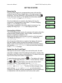
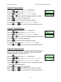
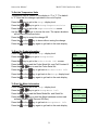
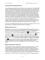
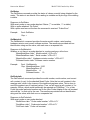
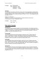
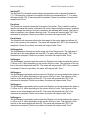
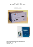
Model 2100 Conductivity Meter Instruction Manual TABLE OF CONTENTS INTRODUCTION ............................................................................................................. 1 Conductivity Probes ..................................................................................................... 1 Features ...................................................................................................................... 1 Unpacking .................................................................................................................... 2 SYMBOLS AND HEADINGS ........................................................................................... 2 GENERAL INFORMATION ............................................................................................. 2 CONTROLS, CONNECTIONS, AND DISPLAY .............................................................. 4 Front Panel .................................................................................................................. 4 Display ......................................................................................................................... 5 Rear Panel ................................................................................................................... 6 Power Supply Connection ........................................................................................... 6 USB Cable Input .......................................................................................................... 6 GETTING STARTED....................................................................................................... 7 Powering Up ................................................................................................................ 7 Connecting a Probe ..................................................................................................... 7 Setup from the Front Panel .......................................................................................... 7 To Set the Display Contrast ..................................................................................... 8 To Set the Display Brightness .................................................................................. 8 To Set the Conductivity Units ................................................................................... 8 To Set the Temperature Units .................................................................................. 9 To Read the Probe Information ................................................................................ 9 To Read the Meter Information ................................................................................ 9 To Set the Cell Constant for a User Probe ............................................................. 10 MAKING MEASUREMENTS ......................................................................................... 11 Display Modes ........................................................................................................... 11 Auto Range Mode .................................................................................................. 11 Display Lock Mode ................................................................................................. 11 Cleaning and Preparing the Probe............................................................................. 12 i Instruction Manual Model 2100 Conductivity Meter Making measurements .............................................................................................. 12 Measurements with a dip probe ................................................................................. 12 Measurements with a flow-through probe .................................................................. 13 USB METER CONTROL AND DATA ACQUISITION.................................................... 13 Introduction ................................................................................................................ 13 USB Commands ........................................................................................................ 14 Data and Information Acquisition Commands ........................................................ 14 Meter Control Commands ...................................................................................... 16 Miscellaneous Commands ..................................................................................... 18 RETURN FOR REPAIR OR CALIBRATION ................................................................. 19 Cleaning and Decontamination .................................................................................. 19 Packing and Shipping ................................................................................................ 19 APPENDIX A – SPECIFICATIONS ............................................................................... 20 APPENDIX B – WARRANTY ........................................................................................ 21 APPENDIX C – DECLARATION OF CONFORMITY .................................................... 22 APPENDIX D – Certificate of Cleaning and Decontamination....................................... 24 ii INTRODUCTION Thank you for purchasing the Model 2100 Conductivity Meter from ILIUM Technology, Inc. The Model 2100 is intended for use as a laboratory instrument and is capable of providing accurate measurements of the temperature and solution conductivities from 1 fS/cm to 1 mS/cm. The meter is completely auto-ranging, with the accessible conductivity range determined by the probe chosen, with each probe spanning over 8 decades of conductivity. Most measurements require simply placing the probe in the sample and reading the conductivity and temperature on the meter’s display. The simple-to-use menu system allows control of the display brightness and contrast, a choice of the conductivity and temperature units displayed, information about the meter and the probe currently in use, and the ability to lock the display into a specific conductivity range if desired. Additional capabilities are available with computer communication with the meter through its USB port. Conductivity Probes The Model 2100 meter is designed to work with a family of conductivity probes, each of which allows the user to access eight decades of conductivity. The standard meter package includes a Model 1020 fully immersible, mini-dip probe, which covers the conductivity range from 25 fS/cm up to a few µS/cm. The parts of the probe that come in contact with the user’s samples are made of 316 stainless steel, PEEK, PTFE, and FEP, depending on the depth that the probe and cable are immersed. The mini-dip probes are designed to be robust, fully immersible, easy to use, and extremely easy to clean. Many solvent based dispersions, such as paints, inks, or water/oil emulsions are difficult to remove from electrode surfaces simply by flushing with additional solvents. The ILIUM dip probes allow the user to remove the outer cylinder, providing access to the electrode surfaces so they can be wiped clean with an appropriate, non-abrasive swab or wipe. Features Auto-ranging meter with ability to lock range Simultaneously capture conductivity and temperature measurements User selectable units for conductivity and temperature Interchangeable, factory-calibrated probes ensure accuracy and accommodate switching between applications Fully-guarded probes to ensure accurate measurements Easy to clean modular design Easy reassembly with no change in cell constant Small sample size (< 3mL) required USB port for control of meter and data acquisition Included data acquisition software tracks data from up to 3 instruments simultaneously 1 Instruction Manual Model 2100 Conductivity Meter Unpacking Check for any damage on the shipping container that might suggest inappropriate handling during shipping. When you first unpack the Model 2100, check to ensure that you find all the items listed on the packing list and look for any signs of damage that may have occurred during shipping. Report any damage to the shipper immediately. Note that there is a protective film over the display window that should be removed before using the meter. The anti-static bag and shipping container should be saved for future shipments, including returns for annual calibration or other service. SYMBOLS AND HEADINGS WARNING This heading in the user documentation explains dangers that might result in personal injury or death. CAUTION This heading in the user documentation explains hazards that could damage the instrument. Such damage may invalidate the warranty. GENERAL INFORMATION CAUTION: Please read this user guide thoroughly before using your meter. Any use outside of these instructions may invalidate your warranty and cause permanent damage to the meter. CAUTION: To clean the instrument, use a damp cloth. Clean the exterior of the instrument only. Do not apply cleaner directly to the instrument or allow liquids to enter or spill on the instrument. To clean the probe, remove the outer cylinder, flush all contaminated surfaces with an appropriate solvent, carefully wipe the electrode surfaces clean with an appropriate, non-abrasive swab or wipe, rinse again with the solvent, then replace the outer cylinder. WARNING: There are no user serviceable parts in this meter. Please return the meter to ILIUM if service is required. CAUTION: This meter is intended for use only with the ILIUM Power Supply included with the meter (ILIUM part no. 01-262-0500001). Use of an AC Adapter other than the one supplied by ILIUM may damage the meter. 2 Instruction Manual Model 2100 Conductivity Meter WARNING: Ensure that the AC Adapter is readily accessible when positioning the device, as it is the main AC disconnect. To fully disconnect the unit from the AC supply, remove the AC Adapter from the wall outlet. CAUTION: This meter is designed to be used only with ILIUM model 2100 compatible probes, adapters, and accessories. The use of probes, adapters, or accessories not specifically listed by ILIUM as compatible with this meter may damage the meter and will void the warranty. A list of all currently available compatible probes and accessories is available from ILIUM. WARNING: If the equipment is not used in accordance with the instructions provided in the User Manual, the protection provided by the conductivity meter may be impaired. WARNING: This manual does not profess to address all of the safety problems associated with the use of the Model 2100 and the samples it is used to measure. It is the responsibility of the user of the meter to establish safety and health practices and determine the applicability of regulatory limitations prior to use. WARNING: When handling and measuring flammable samples and cleaning materials: Ensure that the Model 2100 is located in a sufficiently ventilated area or fume hood. Do not store flammable material near the Model 2100. Do not leave sample containers uncovered. Clean all spills immediately. The specifications, descriptions, drawings, ordering information and part numbers within this document are subject to change without notice. 3 Instruction Manual Model 2100 Conductivity Meter CONTROLS, CONNECTIONS, AND DISPLAY Front Panel The front panel contains the 16 x 2 character display, the probe connector, and seven control keys as shown below in Figure 1. Table 1 lists the control keys and describes the function of each. 16 x 2 Character Display Figure 1 Probe Connector Table 1 Key Name On – Off Function Pressing turns on meter. If on, pressing and holding for 4 seconds turns off meter. Range (Escape) If meter is in normal operating mode, pressing toggles between Auto Ranging (AR) and Display Lock (DL) range mode. If in Menu mode, pressing jumps up one menu level without saving any changes. If meter is in normal operating mode, pressing enters the menu mode. If in menu mode, pressing enters the current selection. In menu mode, moves to the item or menu selection to the left. Menu (Enter) Left Right In menu mode, moves to the item or menu selection to the right. Down In Display Lock (DL) operating mode, decreases display resolution. In menu mode, adjusts a setting down or moves down one menu level. In Display Lock (DL) operating mode, increases display resolution. In menu mode, adjusts a setting up or moves up one menu level without saving any changes. Up All ILIUM Model 2100 compatible probes, adapters, and accessories plug into the front panel Probe Connector. A list of all currently available compatible probes and accessories is available from ILIUM. 4 Instruction Manual Model 2100 Conductivity Meter Display The meter has a 16 character by 2 line, backlit, LCD display. During normal measurement operation the main display screen will appear as shown in Figure 2. Conductivity Conductivity Units Status Mode 35.24pS/cm* AR 25.0ºC Figure 2 Temperature Temperature Units The conductivity will be presented in up to four digits, using 0, 1, or 2 digits to the right of the decimal place. The available units include femtoSiemens (fS), picoSiemens (pS), nanoSiemens (nS), microSiemens (µS), and milliSiemens (mS). As described below in the Getting Started section, the user can choose to see the conductivity values in Siemens per centimeter or Siemens per meter. Note that this setting is persistent over on/off cycles. The temperature is displayed on the second line of the display to the nearest 0.1°. As described below in the Getting Started section, the temperature units can be set to either °C or °F. Note that this setting is persistent over on/off cycles. If the connected probe does not have a temperature sensor, this area will remain blank. If the connected probe does have a temperature sensor, but the meter cannot obtain a reading, it will display “ - - - . -°C” or “ - - - . -°F”. This will occasionally happen when the instrument momentarily cannot get an accurate temperature reading. In this case, the temperature will return shortly. If the temperature does not return, or is never available when you connect the probe, the temperature capability has been damaged and the probe should be returned for repair. The Status is shown just to the right of the conductivity units. An asterisk is shown when the meter has not reached a completely stable reading. Once a stable reading is reached, the asterisk will turn off. This status does not imply that your sample has reached a steady value, but that the instrument is satisfied with the immediate value reported. Occasionally, the value displayed may appear to be stable even though the asterisk is displayed. This indicates that the instrument is not confident in the precision of the answer. In the upper right hand corner of the display, the Mode is designated as either AR for Auto Range mode or DL for Display Lock mode as described in the Making Measurements section below. 5 Instruction Manual Model 2100 Conductivity Meter Rear Panel The rear panel contains the connections for the power supply and USB communications cable as shown below in Figure 3. Figure 3 Power Supply Input USB cable input Power Supply Connection The ILIUM power supply is designed to work with inputs of 100 to 240 VAC at 50 to 60Hz. Units sold in the US are equipped with US standard plugs. However, the plug type is changeable, and a kit is available from ILIUM that provides a selection of plug types for use in other countries. CAUTION: This meter is intended for use only with the ILIUM Power Supply included with the meter. Use of an AC Adapter other than the one supplied by ILIUM may damage the meter. USB Cable Input The USB cable connector accommodates a standard USB Type B plug. The USB connection is used for control of the meter and data acquisition. 6 Instruction Manual Model 2100 Conductivity Meter GETTING STARTED Powering Up Plug the power supply into an appropriate power outlet and the connector into the Power Adapter Input on the back panel of the instrument. Turn the instrument on by pressing the on-off key, . As the instrument starts up, the display will momentarily display Ilium Technology and Initializing... Once the initialization is complete, the display will show the conductivity, the temperature, and either AR, for Auto Ranging mode, or DL for Display Lock mode. If no probe is connected to the meter when it is turned on, the display will simply say No Probe and display the mode. Ilium Technology Initializing... 43.41pS/cm 25.0°C No Probe AR AR Connecting a Probe The ILIUM smart probes contain all necessary information about the probe internally: Model number, serial number, conductivity cell constant, temperature calibration, etc. Simply plug the probe into the probe connector on the front panel. The display will change to Probe Connected, followed by Initializing... Once the probe initialization is complete, the display will return to the main display screen and show the standard information. When a probe is disconnected, the screen will momentarily display the message Probe Disconnect in the top line before changing to the No Probe message. Probe Connected Initializing... 0. fS/cm* AR 25.0°C Setup from the Front Panel Although the instrument is ready to be used at this point, the user may wish to change some of the settings at this time or simply view information about the meter or attached probe. The basic front panel keys and the setup menu will be reviewed here. To enter the setup menu, press the key. The display will change to Setup: in the upper line and Contrast in the lower line. Using and keys (See Table 1) the user can choose which the category to look at. The available items are: Contrast, Brightness, ConductivityUnit, TemperatureUnits, Probes, and Meter Info. The first four allow changes to the meter settings. Probes and MeterInfo provide information. Changes to the display contrast and brightness and the conductivity or temperature units are persistent over meter power cycles. 7 Setup: Contrast Setup: Brightness Setup: ConductivityUnit Setup: TemperatureUnits Setup: Probes Setup: Meter Info Instruction Manual Model 2100 Conductivity Meter To Set the Display Contrast Press the key to get to the Setup: display level. Press the or Press the key to get to the Set Contrast screen Use the and key to get to Setup:Contrast Setup: Contrast Set Contrast Up/Dwn to adjust keys to adjust the display contrast as desired Press the key to accept the change OR Press the key to leave without saving the change The display will go back to the Setup:Contrast screen Press the key or key to go back to the main display screen To Set the Display Brightness Press the key to get to the Setup: display level. Press the or Press the key to get to the Set Brightness screen Use the and key to get to Setup:Brightness Setup: Brightness Set Brightness Up/Dwn to adjust keys to adjust the display brightness as desired Press the key to accept the change OR Press the key to leave without saving the change The display will go back to the Setup:Brightness screen Press the key or key to go back to the main display screen To Set the Conductivity Units Conductivity can be viewed on the display as Siemens/centimeter or Siemens/meter (S/cm or S/m). The default is S/cm. Note that this change is persistent over on/off cycles. Press the key to get to the Setup: display level. Press the or Press the key to get to the ConductivityUnit screen Use the and key to get to Setup:ConductivityUnit keys to choose the units. The square brackets will surround the active choice. Press the key to accept the change OR Press the or the key to leave without saving the change Press the key or key to go back to the main display screen 8 Setup: ConductivityUnit ConductivityUnit [/cm] /meter Instruction Manual Model 2100 Conductivity Meter To Set the Temperature Units Temperature can be viewed on the display in °C or °F. The default is °C. Note that this change is persistent over on/off cycles. Press the key to get to the Setup: display level. Press the or Press the key to get to the TemperatureUnits screen Use the and key to get to Setup:TemperatureUnits keys to choose the units. The square brackets Setup: TemperatureUnits TemperatureUnits [ºC] ºF will surround the active choice. Press the key to accept the change OR Press the or the key to leave without saving the change Press the or the key again to get back to the main display To Read the Probe Information Press the key to get to the Setup: display level. Press the or Press the key to get to the Probes:Probe Info screen Press the key to read the Probe Model No. and Cell Constant K Press the or Press the or the key to get back to Probes:Probe Info Press the or the key to get back to the Setup: display level Press the or the key again to get back to the main display key to get to Setup:Probes key to read the Probe Serial No. Setup: Probes Probes: Probe Info Model: 1003 K= 212.19cm Serial No: 00125 To Read the Meter Information Press the key to get to the Setup: display level. Press the or Press the key to read the Meter Model No. and Serial No. key to get to Setup:Meter Info or key to read the Meter hardware revision and Press the software revision (HW Rev and SW Rev) Press the or the key to get back to Setup:Meter Info Press the or the key again to get back to the main display 9 Setup: Meter Info Model: 2100 Serial No: 00345 HW Rev: AA-BB SW Rev: 1.0.0 Instruction Manual Model 2100 Conductivity Meter To Set the Cell Constant for a User Probe ILIUM supplied smart probes are interchangeable and factorycalibrated to ensure accuracy and accommodate switching between applications. Therefore, this function is not available when a smart probe is connected or if no probe is connected. However, if you will be fabricating your own probes for special applications, you will need to use the ILIUM User Probe Adapter and set the cell constant manually. To do this: Press the key to get to the Setup: display level. Press the or Press the key to get to the Probes:Probe Info screen Press the or Press the key to enter the Set Cell Const. screen Press the key to move the underline to the desired character Use the Setup: Probes key to get to Setup:Probes Probes: Probe Info key to get to Probes:Set Cell Const. and Probes: Set Cell Const. keys to increase or decrease the value Set Cell Const. 0001.00cm Cancel Once the value has been set, press the key to save it To leave this screen without saving the change, you can Press the key until Cancel is in brackets, then press or, Press the Set Cell Const. 0001.00cm Cancel Set Cell Const. 0005.00cm Cancel , key Whether you save the change, cancel, or use the key, you will be back at the Probes:Set Cell Const. screen Press the or the key to get back to the Setup: display level Press the or the key again to get back to the main display Note that our cell constant is the area/gap ratio, which is the inverse of the traditional gap/area value. This is done to avoid the constant use of fractional values. Thus, we will report a cell constant of, for example, 205cm, which would traditionally be reported as 0.00488cm-1. Please remember to enter your cell constant as the effective area/gap in centimeters. 10 Instruction Manual Model 2100 Conductivity Meter MAKING MEASUREMENTS Display Modes The Model 2100 can be operated in either Auto Range mode or Display Lock mode. The user can toggle between these two modes with the RANGE/Esc key to switch from Auto Range mode (AR) to Display Lock mode (DL) at any time. Auto Range Mode The default mode of the Model 2100 is Auto Range, which is indicated by the AR in the upper right hand corner of the display. In this mode, the meter will automatically choose the appropriate units (fS, pS, nS, µS, or mS) and the number of decimal places for the reading. The units will change on the way up when the value reaches 1200 for the previous units. For example, when the reading just exceeds 1200pS/cm, the reading will automatically change to 1.20nS/cm. The change point on the way down is at 0.99. For example, as the value falls below 0.99nS/cm, the reading will automatically change to, for example, 989.9pS/cm. For most general conductivity measurements, this is the best mode to use. Display Lock Mode When it is of interest set the units and number of decimal places manually, the meter can be put into Display Lock mode, which is indicated by the DL in the upper right hand corner of the display. In DL mode the up arrow and down arrow can be used to increase or decrease the display resolution respectively. Each time the down arrow is pressed, one digit to the right of the decimal point will be eliminated. If no digits are displayed to the right of the decimal point, the display will change to the next larger unit with two digits showing. For example, consider a sample reading 90.18pS/cm in AR mode. Initial reading of sample in Auto Range mode ………………………… 90.18pS/cm 25.0°C AR Press the key to change to Display Lock mode …………………. 90.18pS/cm 25.0°C DL Press the key to decrease the display resolution ………………… 90.2 pS/cm 25.0°C DL Press the key again to decrease the display resolution …….…… 90. pS/cm 25.0°C DL Press the key again to decrease the display resolution …………. 0.09nS/cm 25.0°C DL If a sample is measured for which the reading exceeds the range that has been selected, or if the up arrow is used to move to a range for which the current reading is too large, Over range is displayed. 11 Over range 25.0°C DL Instruction Manual Model 2100 Conductivity Meter Cleaning and Preparing the Probe Before making a measurement, ensure that the probe is clean and dry. The Model 1020 and other ILIUM probes are designed to be easily disassembled and reassembled with no loss in accuracy. This feature allows thorough cleaning of the electrode surfaces by flushing with solvent and, if necessary, wiping with an appropriate non-abrasive swab or cloth followed by a second solvent rinse. The solvent can be the same as that of the sample solutions or dispersions. When making measurements of about 100pS/cm or above, this cleaning is often sufficient and the probe can be reassembled and allowed to dry until it comes back to the desired temperature. When your sample conductivities are below a few pS/cm, and especially below 1pS/cm, it is important to ensure that any water is removed from the probe surfaces by flushing with an appropriate drying solvent such as acetone or ethyl acetate. The probe should then be dried with dry air or nitrogen to avoid the formation of condensation on the probe surfaces before the next sample is tested. These precautions may also need to be taken in other ranges when trace quantities of water play a significant role in the behavior of your samples. As always, when handling flammable samples and cleaning materials, be sure to follow the guidelines in the General Information section of this manual. Making measurements Regardless of the probe used, once the sample has filled the measurement space of the probe, the meter will auto range and display the conductivity in the appropriate units along with the measured temperature. If it is desired to constrain the display to a desired range, the user can press the RANGE/Esc key, , to switch from Auto Range mode (AR) to Display Lock mode (DL). Once in DL mode, the up arrow key, , and , can be used to increase or decrease the display resolution as down arrow key, desired. If the actual conductivity of the sample exceeds the range selected, the display will read Over range, but will still provide the temperature. Pressing the RANGE/Esc , again will return the meter to the Auto Range mode. NOTE: Changes to the key, mode and display resolution can also be made through USB commands from an attached computer. See the section USB Meter Control and Data Acquisition for more details. Measurements with a dip probe The Model 2100 is usually supplied with a Model 1020 immersible dip probe. The user simply needs to insert the probe into the sample to be tested and ensure that no bubbles are trapped in the interior of the probe. The probe is completely immersible, but only needs to be inserted so that the liquid is just above the vent holes in the outer cylinder to obtain an accurate reading. The meter will auto range and display the conductivity in the appropriate units along with the measured temperature. Following the measurement, the outer cylinder of the probe can be removed to facilitate cleaning of 12 Instruction Manual Model 2100 Conductivity Meter the inner and outer electrodes as discussed in the previous section Cleaning and Preparing the Probe. Measurements with a flow-through probe Flow-through probes are available for the Model 2100 conductivity meter. These probes can also be disassembled for easy cleaning when necessary, but can often be brought back to the solvent base-line by simply flushing the probe with the appropriate solvent system. If your samples require that you avoid any residual traces of water, the system can be flushed with a solvent such as acetone or ethyl acetate and then dried with dry air or nitrogen. The flow-through probes are provided with Viton O-rings by default. However, other materials are available and should be chosen for compatibility with the chemistry of the sample solutions and the cleaning solvents to be used. USB METER CONTROL AND DATA ACQUISITION Introduction Remote operation of the Model 2100 Conductivity Meter is also available through the USB port on the back panel of the meter. Instrument set up, control, and data acquisition can be carried out from a computer through this interface. The CD provided with the Model 2100 package contains USB Virtual COM port drivers and an easy to use data acquisition program that uses the USB interface to obtain, display, and store data collected from up to three meters simultaneously. Details of this data acquisition program are provided in a separate manual. If you wish to communicate directly with the Model 2100 using your own program or a terminal emulation program, you can do so by first installing the USB Virtual COM port drivers from the CD onto a Windows PC and then connecting the Model 2100 meter to an available USB port on the computer. To begin communication, find the COM port that the operating system has assigned to the meter and set the communication parameters to: Baud Rate = 19200 Data Bits = 8 Parity = None Stop Bits = 1 This section will provide a list of and details for using the USB commands available for meter control and data acquisition. 13 Instruction Manual Model 2100 Conductivity Meter USB Commands There are 7 commands for getting information from the Model 2100 meter, 15 commands for controlling the behavior of the meter, and a command that simply repeats the previous command. Data and Information Acquisition Commands GetData The GetData command provides the present values of conductivity, temperature, and status from the meter. The conductivity is always given in S/m. The temperature is always in ºC. The status is an asterisk, *, if the reading is unstable and a plus sign, +, if the reading is stable. Response to GetData With smart probe attached: Conductivity <tab> Temperature <tab> Status With user probe attached: Conductivity <tab> Temperature <tab> Status With no probe attached: “No Probe” With a probe read error at the time the command is received: “Probe Error” Example: Cmd: GetData Rsp: 7.46e-10 20.812 + GetFreq The GetFreq command provides the frequency in Hz currently being used by meter. Response to GetFreq With smart probe or user probe attached: Frequency in Hz With no probe attached: “No Probe” With a probe read error at the time the command is received: “Probe Error” Example: Cmd: GetFreq Rsp: 18.002 GetVoltage The GetVoltage command provides the peak drive voltage in volts currently being used by the meter. Response to GetVoltage With smart probe or user probe attached: Peak drive voltage in volts With no probe attached: “No Probe” With a probe read error at the time the command is received: “Probe Error” Example: Cmd: GetVoltage Rsp: 9.474 14 Instruction Manual Model 2100 Conductivity Meter GetStatus The GetStatus command provides the status of values currently being obtained by the meter. The status is an asterisk if the reading is unstable and a plus sign if the reading is stable. Response to GetStatus With smart probe or user probe attached: Status (“*” is unstable, “+” is stable) With no probe attached: “No Probe” With a probe read error at the time the command is received: “Probe Error” Example: Cmd: GetStatus Rsp: + GetMeterInfo The GetMeterInfo command provides the meter model number, serial number, hardware revision, and current software revision. The results are provided with an identification string and the value, with each one on a separate line. Response to GetMeterInfo Whether or not there is a probe attached or a probe read error at the time: “MeterModelNum:<tab>” Model number “<CR><LF>” “MeterSerialNum:<tab>” Serial number “<CR><LF>” “MeterHwRev:<tab>” Hardware revision number “<CR><LF>” “SoftwareVersion:<tab>” Software version number Example: Cmd: GetMeterInfo Rsp: MeterModelNum: 2100 MeterSerialNum: 57 MeterHwRev: A SoftwareVersion: 1.0 GetProbeInfo The GetProbeInfo command provides the model number, serial number, and current cell constant (in cm) for the attached Smart Probe. Note that our cell constant is the area/gap ratio, which is the inverse of the traditional gap/area value. This is done to avoid the constant use of fractional values. Thus, we will report a cell constant of, for example, 205cm, which would traditionally be reported as 0.00488cm-1. For a User Probe the model and serial number are for the User Probe Adapter & the cell constant value will be 1 or that set by the user. The results are provided with an identification string and the value, with each one on a separate line. Response to GetProbeInfo With smart probe or user probe attached: “ModelNum:<tab>” Probe model number “<CR><LF>” “SerialNum:<tab>” Probe serial number “<CR><LF>” “CellConst:<tab>” Probe cell constant 15 Instruction Manual Example: Model 2100 Conductivity Meter Cmd: GetProbeInfo Rsp: ModelNum: 1020 SerialNum: 00158 CellConst: 211.000 GetUnits The GetUnits command provides the current units set for panel display readings. Note that changing units only affects the panel readings, not the USB data obtained with the GetData command. The conductivity units are "S/cm" or "S/m". The temperature units are either "C" or "F" Response to GetUnits Whether or not there is a probe attached or a probe read error at the time: Conductivity Units <tab> Temperature Units Example: Cmd: GetUnits Rsp: S/cm C Meter Control Commands DisplayClear The Display Clear command is used to move the meter back to the display level from any point in the menu. This should be done before beginning any programming from the USB port. The meter will respond with “OK” if the command is accepted. If there is a problem, the meter will respond with “Error.” SetUnitsCM The SetUnitsCM command sets the display conductivity units to Siemens per cm (S/cm). Following this command, the display will report the conductivity as fS/cm, pS/cm, nS/cm, µS/cm, or mS/cm. The meter will respond with “OK” if the command is accepted. If there is a problem, the meter will respond with “Error.” SetUnitsM The SetUnitsM command sets the display conductivity units to Siemens per meter (S/m). Following this command, the display will report the conductivity as fS/m, pS/m, nS/m, µS/m, or mS/m. The meter will respond with “OK” if the command is accepted. If there is a problem, the meter will respond with “Error.” SetUnitsTC The SetUnitsTC command sets the display temperature units to degrees centigrade (°C). Following this command, the display will report the temperature as °C. The meter will respond with “OK” if the command is accepted. If there is a problem, the meter will respond with “Error.” 16 Instruction Manual Model 2100 Conductivity Meter SetUnitsTF The SetUnitsTF command sets the display temperature units to degrees Fahrenheit (°F). Following this command, the display will report the temperature as °F. The meter will respond with “OK” if the command is accepted. If there is a problem, the meter will respond with “Error.” PanelLock The PanelLock command locks the front panel of the meter. This is useful for setting specific units and the number of places in DL mode, then locking the meter so operators cannot change the settings. No menu operations are allowed while locked. The locked state is persistent over a power down/up cycle. The meter will respond with “OK” if the command is accepted. If there is a problem, the meter will respond with “Error.” PanelUnlock The PanelUnlock command unlocks the front panel of the meter again and allows full use of the menus by the operators. The meter will respond with “OK” if the command is accepted. If there is a problem, the meter will respond with “Error.” SetRangeAuto The SetRangeAuto command puts the meter into Auto Range mode. The right side of the top line on the meter display will read AR. The meter will respond with “OK” if the command is accepted. If there is a problem, the meter will respond with “Error.” SetRangefs The SetRangefs command puts the meter into Display Lock mode and sets the scale to 0. fS/cm or to 0. fS/m depending on the current choice of units. The right side of the top line on the meter display will read DL. The meter will respond with “OK” if the command is accepted. If there is a problem, the meter will respond with “Error.” SetRangeps The SetRangeps command puts the meter into Display Lock mode and sets the scale to 0. pS/cm or to 0. pS/m depending on the current choice of units. The right side of the top line on the meter display will read DL. The meter will respond with “OK” if the command is accepted. If there is a problem, the meter will respond with “Error.” SetRangens The SetRangens command puts the meter into Display Lock mode and sets the scale to 0. nS/cm or to 0. nS/m depending on the current choice of units. The right side of the top line on the meter display will read DL. The meter will respond with “OK” if the command is accepted. If there is a problem, the meter will respond with “Error.” SetRangeus The SetRangeus command puts the meter into Display Lock mode and sets the scale to 0. uS/cm or to 0. uS/m depending on the current choice of units. The right side of the top line on the meter display will read DL. The meter will respond with “OK” if the command is accepted. If there is a problem, the meter will respond with “Error.” 17 Instruction Manual Model 2100 Conductivity Meter SetRangems The SetRangems command puts the meter into Display Lock mode and sets the scale to 0. mS/cm or to 0. mS/m depending on the current choice of units. The right side of the top line on the meter display will read DL. The meter will respond with “OK” if the command is accepted. If there is a problem, the meter will respond with “Error.” SetPrecInc The SetPrecInc command (Set Precision Increment) increments the display precision in steps. Each time it is called it adds a digit of precision. The meter will respond with “OK” if the command is accepted. If there is a problem, the meter will respond with “Error.” Example: Cmd: Rsp: Cmd: Rsp: Cmd: Rsp: Cmd: Rsp: SetRangens OK (and display now shows 0. nS/cm) SetPrecInc OK (and display now shows 0.0 nS/cm) SetPrecInc OK (and display now shows 0.00nS/cm) SetPrecInc OK (and display now shows 0. pS/cm) SetProbeK <cell constant in cm> The SetProbeK command allows the user to set the cell constant for the meter from the USB port when a User type probe is in use. Response to SetProbeK <cell constant in cm> With smart probe attached: “Smart Probe – can’t set probe K” With user probe attached: Cell constant in centimeters with three decimal places With no probe attached: “No Probe – can’t set probe K” With a probe read error at the time the command is received: “Probe Error” Example: Cmd: SetProbeK 190.24 Rsp: 190.240 Note that our cell constant is the area/gap ratio, which is the inverse of the traditional gap/area value. This is done to avoid the constant use of fractional values. Thus, we will report a cell constant of, for example, 205cm, which would traditionally be reported as 0.00488cm-1. Please remember to enter your cell constant as the effective area/gap in centimeters. Miscellaneous Commands a The “a” command stands for “again,” and simply repeats the last command. It is useful mainly when manually sending commands to the meter with a terminal program while developing a control program. It is most useful for repeating the GetData command or, 18 Instruction Manual Model 2100 Conductivity Meter perhaps, for repeating the SetPrecInc command. However, it will repeat any of the commands. If it is used for the SetProbeK command, the cell constant parameter must be included or an error will be generated. For example, if the command SetProbeK 5.0 was issued, the “a” command would have to be “a 100.00” for example. The responses from the meter will be the same as for the actual commands as noted above. RETURN FOR REPAIR OR CALIBRATION If the meter needs to be returned to ILIUM for repair or is being sent in for calibration, it is necessary to contact ILIUM at 781-333-4000 to let us know why the unit is being returned and to obtain a Return Materials Authorization (RMA) number. It is also required that a Certificate of Cleaning and Decontamination be provided before the meter or probe will be accepted for repair or calibration. See sections below for details and Appendix D for the Certificate of Cleaning and Decontamination. Cleaning and Decontamination Since the ILIUM Model 2100 is designed to be used with a wide range of materials, and the meter can be placed in a laboratory hood environment, it is expected that the meter and probes can become contaminated by the samples tested or other materials used in the same area as the meter. Equipment that has been directly or indirectly exposed to toxic, biological, or radioactive materials needs to be cleaned and/or decontaminated before it can be returned for repair or calibration. For disinfecting the meter, it can be carefully wiped down with a non-abrasive cloth dampened with 70% aqueous isopropyl alcohol solution. To remove organic contamination, the meter surface or front panel can be carefully wiped down with a non-abrasive cloth dampened with isopropyl alcohol. Do not spray the cleaning fluid directly on the meter or allow fluids to enter or spill on the instrument. Be sure that the power cord has been disconnected from the meter before cleaning. When returning a probe it should be cleaned according to the instructions in the Cleaning and Preparing the Probe section above. It is assumed that the meter or probe has been contaminated if it has been used near any radioactive source, and appropriate decontamination procedures must be used if exposure does occur. The customer must certify that the decontamination has been successful and that no radioactivity is detectable using appropriate equipment. Packing and Shipping After cleaning and decontaminating the equipment to be shipped, as described above, carefully pack it in its original packing or the equivalent. Any packing used must protect the meter and probe to avoid damage during shipping. 19 Instruction Manual Model 2100 Conductivity Meter APPENDIX A – SPECIFICATIONS Model 2100 Conductivity Meter Comments Range 1 0 to 0 to 0 to 0 to 0 to 0 to 0 to 0 to 0 to 0 to 0 to 0 to 0 to 0 to 0 to 0 to 999.9 1199. 9999. 99.99 999.9 1199. 9999. 99.99 999.9 1199. 9999. 99.99 999.9 1199. 2000 2.00 fS/cm fS/cm fS/cm pS/cm pS/cm pS/cm pS/cm nS/cm nS/cm nS/cm nS/cm µS/cm µS/cm µS/cm µS/cm mS/cm DL mode only2 0 to 0 to 0 to 0 to 0 to 0 to 0 to 0 to 0 to 0 to 0 to 0 to 0 to 0 to 99.99 999.9 1199. 9999. 99.99 999.9 1199. 9999. 99.99 999.9 1199. 9999. 99.99 200.0 (pS/m) (pS/m) (pS/m) (pS/m) (nS/m) (nS/m) (nS/m) (nS/m) (µS/m) (µS/m) (µS/m) (µS/m) (mS/m) (mS/m) Measured Conductance 5 pS to 0.5 mS Measurement Frequency <1 Hz to 1 kHz Accuracy 1% FS +/- 5 pS + probe error (5 pS to 500 pS) 1% FS +/- 1 digit + probe error (500 pS to 200 uS) 5% FS +/- 1 digit + probe error (200 uS to 0.5 mS) Resolution 4 digits Operating Temperature 5ºC to 40ºC Communications USB Power Supply 5 V DC adapter 100VAC - 240VAC, 50Hz – 60Hz Front Panel Display LCD 2 line 16char Temperature Measurement Range is probe dependent Temperature accuracy 0.5ºC 0 to 65ºC 1.0ºC –40 to 125ºC Temperature resolution 0.1ºC Dimensions 9”x 3.5”x 7.5” (23 x 9 x 19cm) Weight 2.7 lbs (1211 g) + power adapter Enclosure IP 30 1. Available ranges depend on probe in use 2. These ranges available in Display Lock (DL) mode only 20 DL mode only2 DL mode only2 DL mode only2 Instruction Manual Model 2100 Conductivity Meter APPENDIX B – WARRANTY ILIUM Technology, Inc. warrants this product to be free from defects in material and workmanship for a period of one (1) year from date of shipment. During the warranty period, ILIUM Technology will, at its option, either repair or replace any product that proves to be defective. LIMITATION OF WARRANTY This warranty does not apply to defects resulting from product modification without ILIUM Technology’s express written consent, or misuse of any product or part. This warranty also does not apply to software, or problems arising from normal wear or failure to follow instructions. THIS WARRANTY IS IN LIEU OF ALL OTHER WARRANTIES, EXPRESSED OR IMPLIED, INCLUDING ANY IMPLIED WARRANTY OF MERCHANTABILITY OR FITNESS FOR A PARTICULAR USE. THE REMEDIES PROVIDED HEREIN ARE BUYER’S SOLE AND EXCLUSIVE REMEDIES. NEITHER ILIUM TECHNOLOGY, INC. NOR ANY OF ITS EMPLOYEES SHALL BE LIABLE FOR ANY DIRECT, INDIRECT, SPECIAL, INCIDENTAL, OR CONSEQUENTIAL DAMAGES ARISING OUT OF THE USE OF ITS INSTRUMENTS AND SOFTWARE, EVEN IF ILIUM TECHNOLOGY, INC. HAS BEEN ADVISED IN ADVANCE OF THE POSSIBILITY OF SUCH DAMAGES. SUCH EXCLUDED DAMAGES SHALL INCLUDE, BUT ARE NOT LIMITED TO: COST OF REMOVAL AND INSTALLATION, LOSSES SUSTAINED AS THE RESULT OF INJURY TO ANY PERSON, OR DAMAGE TO PROPERTY. 21 Instruction Manual Model 2100 Conductivity Meter APPENDIX C – DECLARATION OF CONFORMITY Manufacturer’s Name: Manufacturer’s Address: ILIUM Technology, Inc. 242 East Border Road Medford, MA 02155 USA Declares that: The Model 2100 Conductivity Meter Conforms with the following Directives: Low Voltage Directive (2006/95/EC) EMC Directive (2004/108/EC) It conforms with the following Standards: EMC IEC 61326-1 CISPR 11:2009+A1:2010 / EN 55011:2009+A1:2010 IEC 61000-4-2:2008 / EN 61000-4-2:2008 IEC 61000-4-3:2010 / EN 61000-4-3:2010 IEC 61000-4-4:2012 / EN 61000-4-4:2012 IEC 61000-4-5:2005 / EN 61000-4-5:2005 IEC 61000-4-6:2008 / EN 61000-4-6:2008 IEC 61000-4-11:2004 / EN 61000-4-11:2004 Group 1 Class A 4 kV CD, 8 kV AD 3 V/m (80-1000 MHz) 3V/m (1.4GHz-2.0GHz) 1V/m (2.0 GHz-2.7GHz) 1 kV power lines 0.5 kV line-line, 1 kV line-ground 3 V (0.15 MHz-80 MHz) 100% Dip (0.5 cycle, 1 cycle) 70% Dip (25 cycles) 100% interruptions (250 cycles) Safety IEC 61010-1:2010 / EN 61010-1:2010 Canada: CAN/CSA-C22.2 No. 61010-1:2012 USA: ANSI/UL 61010-1:2012 Date: March 1, 2014 ______________________ WEEE Compliance This product is required to comply with the European Union’s Waste Electrical and Electronic Equipment (WEEE) Directive 2002/96/EC. It is marked with the following symbol: 22 Instruction Manual Model 2100 Conductivity Meter FCC Part 15 RADIO AND TELEVISION INTERFERENCE NOTE: This equipment has been tested and found to comply with the limits for a Class A digital device, pursuant to Part 15 of the FCC rules. These limits are designed to provide reasonable protection against harmful interference when the equipment is operated in a commercial environment. This equipment generates, uses and can radiate radio frequency energy and, if not installed and used in accordance with the instruction manual, may cause harmful interference to radio communications. Operation of this equipment in a residential area is likely to cause harmful interference in which case the user will be required to correct the interference at their own expense. 23 Instruction Manual Model 2100 Conductivity Meter APPENDIX D – Certificate of Cleaning and Decontamination Company: ________________________________________________________ Department:_______________________________________________________ Address:__________________________________________________________ City: _________________________________ State: _____ Zip: _____________ Country: _______________________________ Phone: ________________________________ Instrument(s) being returned: Model No.: _______________ Serial No.: ________________ Model No.: _______________ Serial No.: ________________ Model No.: _______________ Serial No.: ________________ Model No.: _______________ Serial No.: ________________ Model No.: _______________ Serial No.: ________________ Contaminants (if known): ____________________________________________ Cleaning Agent(s) used: _____________________________________________ Has there has been radioactive exposure? _____ Yes _____ No Radioactive Decontamination Certified? _____ Yes _____ No ______ N/A Cleaning and Decontamination Certified By: Signature: __________________________________ Date: _______________ Name: _____________________________________ Title: ______________________________________ 24 Instruction Manual Model 2100 Conductivity Meter 03/05/2014 09-02100-90010 Rev A 25