1
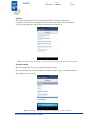
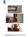
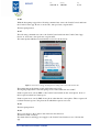
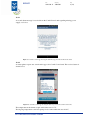
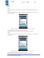
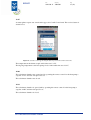
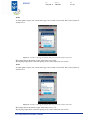
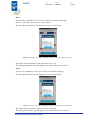
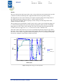
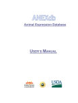
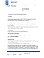
REPORT
Contact person
Date
Enar Andersson
2013-06-11 3P03701
Reference
Page
1 (22)
Energy Technology
+46 10 516 59 56
[email protected]
Innovate Solutions oü
Sihi 42 Tallin Estonia
116 22
Testing of Air Patrol Heat Pump Controller
Assignment
SP has performed testing of an Air Patrol Heat Pump Controller – Combi Control as an
assignment from Innovate Solutions oü.
The Air Patrol Heat Pump Controller – Combi Control is a product making it possible to
control and supervise an air to air heat pump using a mobile phone.
The tested product was a version of the Air Patrol Heat Pump Controller called Combi
Control, which is in general the same product as the Air Patrol Heat Pump Controller.
The difference is that the Combi Control is designed to work specifically with Toshiba heat
pumps. Therefore, the air to air heat pump which was used when testing the Combi Control
unit was a Toshiba.
The testing was performed with the heat pump’s indoor unit placed in a calibrated calorimeter
chamber and the outdoor unit placed in a climate chamber. The Combi Control was mounted
and tested in the calibrated calorimeter chamber.
Object tested
Combi Control, unit with serial number C1109102326250489.
Time and place for the testing
The testing was performed at SP, Energy Technology, the 6th of May 2013.
Date of arrival of equipment
The equipment to be tested was delivered to SP on the 3rd of May 2013.
Method of testing
The testing was performed with the outdoor part of the heat pump placed in a climate
controlled chamber with a stabilized measured dry bulb temperature of 7.1˚C and a calculated
wet bulb temperature of 6.0˚C.
The climate was constant during the test and continuously regulated.
The indoor part of the heat pump was placed in a calibrated calorimeter chamber with varying
temperature. During one part of the test the heat pump was tetsed at 100 % of the unit’s
maximum capacity, the temperature setting on the remote controller is set to maximum and the
derired temperature is obtained by regulating the cooling load of the calorimeter room. During
another part of the test the unit was tested by changing the temperature setting on the remote
SP Technical Research Institute of Sweden
Postal address
Office location
Phone / Fax / E-mail
SP
Box 857
SE-501 15 BORÅS
Sweden
Västeråsen
Brinellgatan 4
SE-504 62 BORÅS
+46 10 516 50 00
+46 33 13 55 02
[email protected]
This document may not be reproduced other than in full, except with the
prior written approval of SP.
Date
REPORT
Reference
2013-06-11 3P03701
Page
2 (22)
controller to different valules, thus resulting in testing the unit at heating capacity less than the
unit’s maximum capacity.
The Combi Control unit was placed in the calorimeter chamber in various positions (both
positions in accordance to the user guide and positions not following the instructions in the
user guide) and the heat pump was supervised as it reacted to the Combi Control’s controlling
commands.
The Combi Control app was installed on a mobile phone using Android.
Direct commands to the Combi Control unit was sent both from an Android mobile phone as
well as an iOS mobile phone.
Installation and configuration
The installation of the SIM-card and installation of the app on the Android mobile phone was
performed by following the instructions in the Quick start guide, found here:
http://combicontrol.net/wp-content/uploads/2012/05/Combi-quick-setup.pdf
The Combi Control app version used was 1.0.33. The app was downloaded on the 6th of May
2013.
The operation of the app and SMS-commands was performed in accordance to descriptions in
the user manual, found here:
http://combicontrol.net/wp-content/uploads/2012/05/cc_manual_web_eng_fin_swe_nok_4.pdf
Equipment
Calorimeter chamber, LL1
Outdoor climate chamber, LV2
Electrical power meters, Inv. Nr. 200452, 200453, 202655
Data logging equipment, Inv. Nr. 201553, 202681
Air temperature sensors, Pt 100 and thermocouple
Heat pump, Toshiba. Indoor unit model no.: RAS-25N3KVP-ND. Outdoor unit model no.:
RAS-25N3AVP-ND
Mobile phone HTC One S
Mobile phone iPhone 4
Uncertainty of measurement
The results from the test are based on measurements. The total uncertainty of measurement of
the results in the report has been calculated in accordance with the following estimates of
uncertainties of measurement and calculation. The estimates are those of the total
uncertainties, including both systematic and random uncertainties.
Temperatures, test points
Tvbin_m
Thermocouple
± 0.2 K
± 1.0 K
Other quantities
PEvpa
± 0,5 %
SP Technical Research Institute of Sweden
REPORT
Date
Reference
2013-06-11 3P03701
Page
3 (22)
Settings
The Combi Control unit tested was given the name Lab1 in the app by the user at
configuration. The version and other information obtained from the version information
request sent from the app to the Combi Control unit are shown below.
Figure 1: Screenshot of the app showing version information and operating status for the Combi Control unit
General settings
The heat pump model was set to a general Toshiba heat pump.
The owner number was set to the number to the phone using the app, i.e. the Android phone.
The settings are shown below.
Figure 2: Screenshot of the app showing the basic settings for the Combi Control unit
SP Technical Research Institute of Sweden
REPORT
Date
Reference
2013-06-11 3P03701
Page
4 (22)
Test proceeding
The test object was installed to a wall plug for battery charging at 14:00 the 4th of May.
The charging was stopped at 06:00 the 6th of May as the equipment then was unplugged from
the power supply. At this time the unit was turned off by pushing the reset button one time.
The unit was turned off during transport to the laboratory.
The equipment was again connected to a wall plug as it arrived to the laboratory. The Combi
Control unit to be tested was again switched on as it was connected to a wall plug.
08:10
The climate chamber and calorimeter chamber were started.
The initial testing procedure was performed by regulating the cooling load of the calorimeter
room to achieve a temperature to the heat pump’s air intake, of 20 C. The heat pump is
operating at its maximum heating capacity at an outdoor air temperature (wet bulb air
temperature) of +7(6) C.
10:55
The temperature state in the outdoor climate chamber was stabilized and the heat pump was
running on maximum power with a an ingoing temperature to the heat pump’s indoor unit of
20˚C.
In the diagrams shown in this report the the electrical power input to the heat pump is shown
as Pevpa and the ingoing temperature to the heat pump’s indoor unit is shown as Tvbin_m.
The Tvbin_m is the calculated mean value from 4 temperature sensors placed at the indoor
unit’s air intake side.
In this report, when referring to the ingoing temperature to the heat pump’s indoor unit, the
Tvbin_m variable is being referred to.
10:57
The Combi Control unit was installed in the indoor calorimeter chamber and the self-test was
ran by pushing the Test button on the Combi Control.
When the Test button was pushed, the heat pump stopped.
The Combi Control was installed beside the heat pump according to the user guide, see next
page.
A thermocouple was placed close to the temperature sensor on the Climate Control unit,
providing appsoximate temperature readings.The thermocouple is shown in the images on the
next page and marked by a green circle in Figure 6.
SP Technical Research Institute of Sweden
REPORT
Date
Reference
2013-06-11 3P03701
Page
5 (22)
Figure 3: Image showing the positioning of the Combi Control unit.
Figure 4: Image showing the positioning of the Combi Control unit.
Figure 5: Image showing the positioning of the Combi Control unit with the thermocouple marked in the green
circle.
SP Technical Research Institute of Sweden
REPORT
Date
Reference
2013-06-11 3P03701
Page
6 (22)
11:00
With the heat pump stopped, the following command was sent to the Combi Control unit from
the Combi Control app: Power on, mode auto, fan speed auto, setpoint 30˚C.
The heat pump started.
11:15
The following command was sent to the Combi Control unit from the Combi Control app:
Power on, mode auto, fan speed max, setpoint 30˚C.
The status update which was automatically received is shown below.
Figure 6: Screenshot of the app showing the new settings sent to the Combi Control unit.
The temperature at the thermocouple at this time was 19.6˚C.
The ingoing temperature to the heat pump’s indoor unit at this time was 19.0˚C.
Status requests were sent by SMS to the Combi Control unit from the owner phone. None of
these request resulted in a status report.
Status requests were sent by SMS from a phone other than the owner phone. These requests all
resulted in status reports to the phone from which the requests were sent.
11:16
The heat pump started.
11:41
The power supply to the Combi Control unit was disconnected.
The unit now ran on battery.
The alarm time for missing power supply to the Combi Control unit was set to 1h from the
app.
SP Technical Research Institute of Sweden
REPORT
Date
Reference
2013-06-11 3P03701
Page
7 (22)
11:42
The testing procedure is changed so that the regulation of the cooling load of the calorimeter
room is fixed. The indoor air temperature will now be regulated by the heat pump and its
control system
12:00
An alarm message was received from the CombiControl unit regarding missing power supply,
see below.
Figure 7: Screenshot of the app showing the alarm message from the Combi Control unit.
A status update request was also sent from the app to the Combi Control unit. The received
status is shown below.
Figure 8: Screenshot of the app showing the status report from the Combi Control unit.
The temperature at the thermocouple at this time was 22.7˚C.
The ingoing temperature to the heat pump’s indoor unit at this time was 22.4˚C.
SP Technical Research Institute of Sweden
REPORT
Date
Reference
2013-06-11 3P03701
Page
8 (22)
12:32
A second alarm message is received from the CombiControl unit regarding missing power
supply, see below.
Figure 9: Screenshot of the app showing the alarm message from the Combi Control unit.
12:34
A status update request was sent from the app to the Combi Control unit. The received status is
shown below.
Figure 10: Screenshot of the app showing the status report from the Combi Control unit.
The temperature at the thermocouple at this time was 23.7˚C.
The ingoing temperature to the heat pump’s indoor unit at this time was 22.9˚C.
SP Technical Research Institute of Sweden
REPORT
Date
Reference
2013-06-11 3P03701
Page
9 (22)
12:46
A status update request was sent from the app to the Combi Control unit. The received status is
shown below.
Figure 11: Screenshot of the app showing the status report from the Combi Control unit
The temperature at the thermocouple at this time was 23.6˚C.
The ingoing temperature to the heat pump’s indoor unit at this time was 23.0˚C.
12:51
The power supply was again connected to the Combi Control unit.
A status update request was sent from the app to the Combi Control unit. The received status is
shown below.
Figure 12: Screenshot of the app showing the status report from the Combi Control unit
The temperature at the thermocouple at this time was 23.3˚C.
The ingoing temperature to the heat pump’s indoor unit at this time was 23.0˚C.
SP Technical Research Institute of Sweden
REPORT
Date
Reference
2013-06-11 3P03701
Page
10 (22)
12:55
A new favorite with the current settings was created in the app by pushing the heart button in
the app.
Also, A status update request was sent from the app to the Combi Control unit. The received
status is shown below.
Figure 13: Screenshot of the app showing the status report from the Combi Control unit.
The temperature at the thermocouple at this time was 23.7˚C.
The ingoing temperature to the heat pump’s indoor unit at this time was 23.0˚C.
13:07
A status update request was sent from the app to the Combi Control unit. The received status is
shown below.
Figure 14: Screenshot of the app showing the status report from the Combi Control unit.
The temperature at the thermocouple at this time was 23.5˚C.
The ingoing temperature to the heat pump’s indoor unit at this time was 23.0˚C.
SP Technical Research Institute of Sweden
Date
REPORT
Reference
Page
2013-06-11 3P03701
11 (22)
The diagram below shows the electrical power input to the heat pump and the temperature in
the chamber between 11:15 and 13:07 i.e. the time when the command representing the 30˚C
Max Auto favourite was active.
2200
24
2180
23
2160
2140
22
2100
21
2080
20
2060
2040
19
2020
2000
172,8
18
192,8
212,8
232,8
252,8
272,8
Mättid [min]
Figure 15: Diagram showing power and temperature.
SP Technical Research Institute of Sweden
T [°C]
Q [W]
2120
Pevpa
Tvbin_m
REPORT
Date
Reference
2013-06-11 3P03701
Page
12 (22)
13:08
By sending the following command via SMS, new setpoints, were sent to the Combi Control
unit from the iPhone (i.e. not the phone with the app installed): Power on, mode auto, fan
speed max, setpoint 22˚C.
A status update request was sent from the app to the Combi Control unit. The received status is
shown below.
Figure 16: Screenshot of the app showing the status report from the Combi Control unit.
The temperature at the thermocouple at this time was 23.7˚C.
The ingoing temperature to the heat pump’s indoor unit at this time was 23.4˚C.
13:19
A status update request was sent from the app to the Combi Control unit. The received status is
shown below.
Figure 17: Screenshot of the app showing the status report from the Combi Control unit.
The temperature at the thermocouple at this time was 19.3˚C.
The ingoing temperature to the heat pump’s indoor unit at this time was 18.4˚C.
SP Technical Research Institute of Sweden
REPORT
Date
Reference
2013-06-11 3P03701
Page
13 (22)
13:30
A status update request was sent from the app to the Combi Control unit. The received status is
shown below.
Figure 18: Screenshot of the app showing the status report from the Combi Control unit.
The temperature at the thermocouple at this time was 19. 7˚C.
The ingoing temperature to the heat pump’s indoor unit at this time was 18.9˚C.
13:34
A power off (stop) command was sent to from the app to the Combi Control. The heat pump
stops. The status update which was automatically received is shown below.
Figure 19: Screenshot of the app showing the status report from the Combi Control unit.
The temperature at the thermocouple at this time was 20.8˚C.
The ingoing temperature to the heat pump’s indoor unit at this time was 20.1˚C.
SP Technical Research Institute of Sweden
REPORT
Date
Reference
2013-06-11 3P03701
Page
14 (22)
13:37
The following commands were sent to the Combi Control unit from the app:
Power on, mode auto, fan speed auto, setpoint 18˚C.
The status update which was automatically received is shown below.
Figure 20: Screenshot of the app showing the status report from the Combi Control unit.
The temperature at the thermocouple at this time was 20.7˚C.
The ingoing temperature to the heat pump’s indoor unit at this time was 20.5˚C.
13:45
A version information request was sent to the Combi Control unit from the app. The received
message is shown below.
Figure 21: Screenshot of the app showing the status report from the Combi Control unit.
SP Technical Research Institute of Sweden
REPORT
Date
Reference
2013-06-11 3P03701
Page
15 (22)
13:47
A status update request was sent from the app to the Combi Control unit. The received status is
shown below.
Figure 22: Screenshot of the app showing the status report from the Combi Control unit.
The temperature at the thermocouple at this time was 13.9˚C.
The ingoing temperature to the heat pump’s indoor unit at this time was 14.2˚C.
14:06
The calorimeter chamber was opened and by operating the remote control for the heat pump a
setpoint of 18˚C and auto fan speed was set.
The calorimeter chamber was closed.
14:13
The calorimeter chamber is opened and by operating the remote control for the heat pump a
setpoint of 20˚C and max fan speed is set.
The calorimeter chamber is closed.
SP Technical Research Institute of Sweden
REPORT
Date
Reference
2013-06-11 3P03701
Page
16 (22)
14:20
A status update request was sent from the app to the Combi Control unit. The received status is
shown below.
Figure 23: Screenshot of the app showing the status report from the Combi Control unit.
The temperature at the thermocouple at this time was 15.0˚C.
The ingoing temperature to the heat pump’s indoor unit at this time was 14.6˚C.
14:28
A status update request was sent from the app to the Combi Control unit. The received status is
shown below.
Figure 24: Screenshot of the app showing the status report from the Combi Control unit.
The temperature at the thermocouple at this time was 18.7˚C.
The ingoing temperature to the heat pump’s indoor unit at this time was 18.5˚C.
SP Technical Research Institute of Sweden
REPORT
Date
Reference
2013-06-11 3P03701
Page
17 (22)
14:52
The following commands were sent to the Combi Control unit from the app:
Power on, mode auto, fan speed max, setpoint 30˚C.
The status update which was automatically received is shown below.
Figure 25: Screenshot of the app showing the status report from the Combi Control unit.
The temperature at the thermocouple at this time was 18.1˚C.
The ingoing temperature to the heat pump’s indoor unit at this time was 18.1˚C.
14:59
A power off command was sent to the Combi Control unit from the app.
The status update which was automatically received is shown below.
Figure 26: Screenshot of the app showing the status report from the Combi Control unit.
The temperature at the thermocouple at this time was 20.0˚C.
The ingoing temperature to the heat pump’s indoor unit at this time was 19.8˚C.
SP Technical Research Institute of Sweden
REPORT
Date
Reference
2013-06-11 3P03701
Page
18 (22)
15:03
The placement of the Combi Control unit was changed to a position opposite to the indoor part
of the heat pump.
The command power on was sent from the app to the Combi Control.
The pump started. The status update which was automatically received is shown below.
Figure 27: Screenshot of the app showing the status report from the Combi Control unit.
The temperature at the thermocouple at this time was 20.8˚C.
The ingoing temperature to the heat pump’s indoor unit at this time was 20.3˚C.
15:06
The placement of the Combi Control unit was changed to a position in the ceiling in the
chamber.
The command power off was sent from the app to the Combi Control.
The pump stops.
15:07
The placement of the Combi Control unit was changed to a position where the unit was placed
on the floor with one IR-transmitter facing down toward the floor in the chamber. The
placement is shown below.
SP Technical Research Institute of Sweden
REPORT
Date
Reference
2013-06-11 3P03701
Page
19 (22)
Figure 28: Image showing the positioning of the Combi Control unit with the unit marked in the green circle.
The indoor part of the heat pump is shown to the left in the image.
The command power on was sent from the app to the Combi Control three times.
There was no reaction from the heat pump.
15:08
The placement of the Combi Control unit was changed to a position where the unit was placed
on the floor in the chamber with the IR-transmitter facing up. The placement is shown below.
Figure 29: Image showing the positioning of the Combi Control unit with the unit marked in the green circle.
SP Technical Research Institute of Sweden
REPORT
Date
Reference
2013-06-11 3P03701
Page
20 (22)
The command power on, mode auto, fan speed max, setpoint 30˚C was sent from the app to
the Combi Control.
The heat pump started.
The status update which was automatically received is shown below.
Figure 30: Screenshot of the app showing the status report from the Combi Control unit.
The ingoing temperature to the heat pump’s indoor unit at this time was 18.4˚C.
15:11
The Combi Control unit is disconnected from the power supply and removed from the
chamber. An alarm message was received before the SIM-card was removed from the Combi
Control unit, see below.
Figure 31: Screenshot of the app showing the status report from the Combi Control unit.
SP Technical Research Institute of Sweden
Date
REPORT
Reference
Page
2013-06-11 3P03701
21 (22)
Results
The test results given in this report relate only to the specific item tested and under the specific
conditions described, with the specific equipment named and at the specified settings.
The diagram below shows the electrical power input to the heat pump and the temperature in
the chamber during the testing procedure i.e. between 10:57 and 15:11.
The electrical power input to the heat pump is shown as Pevpa and the temperature in the
chamber is shown as Tvbin_m.
The performed tests show that the Combi Control is able to turn on and off the heat pump and
to control the heat pump by fan speed and outgoing temperature when setpoints are changed.
During the tests, the Combi Control unit did only control and affect the heat pump when the
Combi Control was supposed to do so, i.e. there were no false commands sent.
Since the Combi Control unit does not receive feebback from the heat pump, the app reflects
the status of the Combi Control unit and not the heat pump. This can be seen for example when
the remote control which is supplied with the heat pump is used for controlling the heat pump
in between commands sent from the CombiControl unit.
24
2000
22
20
18
1000
16
500
14
0
154,8
12
204,8
254,8
304,8
354,8
404,8
Mättid [min]
Figure 32: Diagram showing power and temperature.
SP Technical Research Institute of Sweden
T [°C]
Q [W]
1500
Pevpa
Tvbin_m