1
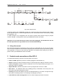
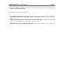
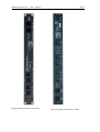
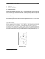
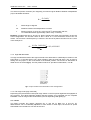
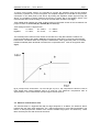
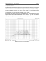
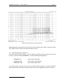
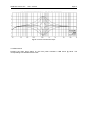
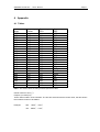
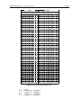
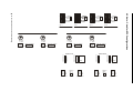
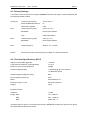
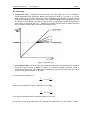
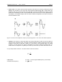
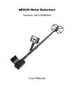
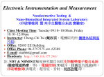
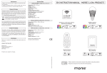
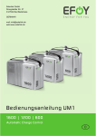
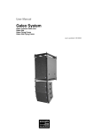
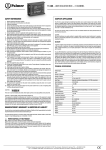
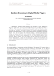
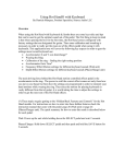
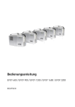
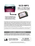
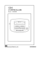
SEEBURG acoustic line
active systempanel 2.5
User Manual
Oktober 2003
TABLE OF CONTENT
1 INTRODUCTION
1.1 Using This Manual
1
2
2 CONTROLS AND CONNECTIONS
2
3 THE SP2.5 FUNCTIONS
5
3.1 Active Crossover
3.1.1 Setting the crossover frequency
3.1.2 Phase correction
3.1.3 High-Mid attenuation
3.1.4 Fullrange mode
3.2 Limiter
6
3.3 Subsonic and Ultrasonic Filter
7
3.4 Equalizer
3.4.1 Setting the Filterwidth
3.4.2 Bassboost
8
8
9
4 APPENDIX
10
4.1 Tabels
11
4.2 Note - Chart for SP2.5 - Configurations
12
4.3 Factory Settings
13
4.4 Technical Specifications SP2.5
13
4.5 Glossary
14
SEEBURG acoustic line
1
SP2.5 User Manual
Page 1
Introduction
Congratulations! With the SEEBURG acoustic line SP2.5 you have purchased a versatile and
professional controller for touring and installed applications. It´s flexible possibilities make the SP2.5
suitable and compatable for existing PA Systems. Operating in analog technology, it uses only
highest grade components and garantees a very natural and first-class sound reproduction.
Please read this manual carefully to allow your system to achieve it’s full potential. Keep
this manual for further reference.
The SP2.5 is used as a link between amplifiers and loudspeakers (Fig.1). It combines an active 2way stereo crossover, system Controller and a I/O connection panel in a standard 19" housing
using only one rack space (1U).
Amp.HighMid
MischMixing
Desk
pult
Amp. Sub
Am p. Bass
fig 1 connection diagram SP2.5
SEEBURG acoustic line
SP2.5 Manual
Page 2
Schaltbar
von
Frontplatte
Subsonic
Bassboost
Ultrasonic
ST4
EQ1
Unsymm.
35Hz
18dB
Tiefpass
20kHz
18dB
C12
C13
+ 6dB
40-80Hz
100Hz 2,2kHz
Phase
Limiter
ST5
Über
Senseleitung
Phase
Gain
180°
ST7
EQ2
Symmetrierung
480Hz 11kHz
Hochpass
R68
EQ3
Fullrange
Schaltbar
von
Frontplatte
dito
Hochpass
Tiefpass
Phase
R117
R120
P4
Gain
P5
0dB bis
-13dB
C43
C44
Über
Senseleitung
Symmetrierung
Limiter
Sub out
Symmetrierung
fig 1 block diagram SP2.5
If ordered together with a SEEBURG acoustic line system the SP2.5 will be delivered with settings
for the specific system. For allround applications the 2.5 will be delivered with a STD factory setting
(see appendix, 4.3).
To make changes in the configuration the unit must be opened, SIPs (resistor arrays) or jumpers
must be changed. In doubt please contact your SEEBURG acoustic line dealer.
Important: The unit must be shut off, mains should be unplugged. The manufacterer will not
be held responsible for any problems due to unortherized handling!
1.1 Using this manual
We will briefly describe the teminology used to help you understand the unit and it´s functions.
Since we cannot explain all technical terms regarding electroacoustics we have provided a glossary
in the appendix. In case you come about any questions or problems while setting up your SP 2.5,
please contact you SEEBURG acoustic line dealer.
2
Controls and connections of the SP2.5
You will find the following controls on the front panel of the SP2.5:
• Power on-LED: Signals the presence of Mains (plugged in and switched on).
• Audio in Channel A and B: Indicates presence of input singnal (from Mix) for Channel A and B.
• Link to next panel Channel A and B: Parallel link out of the unprocessed input signal, i.e. to
other SP2.5 units or Amplifiers.
• Signal A/B-LED: Indicates the presence of an input signal with a level over -20dB.
• Bass boost : The additional bass boost (+6dB @ 55Hz) is switchable at the front panel. The
LED next to the switch will light up if active.
• Fullrange (mounted decreased to prevent accidential switching): This switch changes the highmid output to Fullrange mode. The according LED will light up if active.
• Limit-LEDs for woofer and high-mid: The four LEDs will light up if limiters are active.
SEEBURG acoustic line
SP2.5 Manual
Page 3
• output to speakers: Speakon connectors for speaker connection. Pins 1+/- carry the high-mid
signal, Pins 2+/- the bass signal.
Rear panel connectors on the of the SP2:
• Amp Return woofer and high-mid: Speakon connectors (coding: 1+/-=A; 2+/-=B) for
connecting amplifier outputs to the SP2.5 inputs. Please check for correct polarity. (NL4FC is
1:1)
• Signal to Amp sockets for high-mid A/B and woofer (bass) A/B: Connectors for connecting
the outputs of the SP2.5 to the corresponding amplifier inputs.
• Sub out (mono): This connector carries a additional bass mono signal which can be adjusted in
phase & level using the controls PHASE & LEVEL.
SEEBURG acoustic line
SP2.5 Manual
fig 2 Front panel connectors and controls
Page 4
fig 3 Rear panel connectors and controls
SEEBURG acoustic line
3
SP2.5 Manual
Page 5
SP2.5 Functions
3.1 Active Crossover
The integrated 2-way crossover divides the audio spectrum into passbands for each transducer and
distributes the preamplified signal from the mixer to the corresponding amp channels for bass, mid
& high frequencies. The crossover frequencies are set using risistor arrays (SIPs). The bass band
is limited by an highpass filter, the hi-mid band is limited by an lowpass Filter, both typs are
Butterworth with 24dB/octave slopes.
The following parameters can be edited:
3.1.1 Cutoff frequency
By using different resistor values (SIPs) the crossovers cutoff frequencies can be set, also allowing
the bands to overlap. The resistor values are listed in the appendix in table 1.
3.1.2 Phase correction
Difference in phase between the two bands can be adjusted by altering the phase of the bass band
(0° to 180°, lightgreen jumper in positions 0. 35, 70, 105, 140 or 180). The phase of the hi-mid band
can be reversed by 180°. To do this set the corresp onding lightgreen jumper to position 180.
This phase correction can be usefull in case the acoustic centres of two loudspekers radiating the
same frequency are horizontally not in plane (transducer alignment). This geometrical distance lets
the acoustic energy radiated by the closer loudspeaker arrive the listeners ear earlier due to the
1
shorter distance it has to travel, resulting in unwanted interference at that particular frequency.
fig 4 phase correction
1
see glossary / appendix
SEEBURG acoustic line
SP2.5 Manual
Page 6
The amount of phase correction (Φ in degrees) you need at a given distance between loudspeakers
(∆s) is calculated as follows:
Φ=
∆s ⋅ 360°⋅ f
c
φ:
Phase angle in degrees
∆s:
Distance between the loudspeakers in meters
c:
Speed of sound (in air at 101,3 hPa and 20 οC approximatly 340 m/s;
c increases/decreases approximatly 0,6m/s every 1° Celsius)
Example: A wedge with two 12“ and one 2“ drivers needs to be setup using the SP2.5 in two-way
active configuration. The acoustic centre of the 2” driver is 11,5 cm behind the center of the 12”
drivers. The crossover cutoff frequency is 1500 Hz. The amount of phase correction for the 11,5cm
in this example is:
Φ=
0,115m ⋅ 360°⋅1500 1s
340 ms
= 182,64° ≈ 180°
3.1.3 High-Mid Attenuation
The high-mid attenuator allows the high-mid band to be attenuated in 2,5dB steps in relation to the
bass band, i.e. if the bass driver has a lower efficiancy than the high-mid driver. This is done by
setting the red jumper on the circuit board to the desired position. The amount of attenuation is
listed next to the socket (fig.5). The first position marked “0” provides no attenuation, or 0 dB.
fig 5 Jumper socket for the attenuation in the mid-high band
3.1.4 Full range mode (high-mid band)
Depressing the (decreased mounted) full range switch on the front panel bypasses the highpass of
the crossover. This allows fullrange capable mid-high systems to be operated over the complete
bandwidth. This full range mode is indecated by the corresponding LED lighting up.
3.2 Limiter
The SP2.5 includes four limiters (high-mid CH. A und CH. B, Bass CH. A und CH. B).
attack/release can be individually adjusted for each limiter in three steps, the amount of power
transmitted to the transducers can also be set here.
SEEBURG acoustic line
SP2.5 Manual
Page 7
To insure correct limiter function it is important to connect the speakers using the two speakon
connectors (“speaker out”) on the front panel. The amplifier outputs are connected via “amp return”
connectors on the back panel of the SP2.5. By feeding the amplifiers output signal through the
SP2.5, it is possible to exactly measure the amount of power fed to the speaker drivers. This
measurement with internal sensing is a must for acurate limiter operation (see fig.1).
Time related limiter settings are made via blue jumpers in the limiter section of the circutboard. The
jumper sockets are labeld fast (A), medium (B) and slow (C):
Time settings for bass- & high-mid are:
Bass:
HighMid:
A = 20ms,
A = 10ms,
B = 100ms,
B = 40 ms,
C = 200ms
C = 100ms
The maximal power values for each limiter are set with four 5-way DIP switches. Positions for
power and impedance are listed in table 2 in the appendix. Red LEDs on the front panel indicate
limiter action. The SP2.5 limiter has a dynamic characteristic, which means the power is not totally
2
limited immediately when threshold is reached, the compression ratio rises as amp power does
(fig.6).
fig 6 principle limiter charactertistic. The LED will light at point A. The compression ratio then rises as
input signal does (range between point A & point B). The maximum compression ratio of
approximately 1:20 is reached after the input signal reaches point B.
3.3 Subsonic and ultrasonic filter
The subsonic-filter is a highpass filter with an edge steepness of 18 dB/oct, the ultrasonic filter a
lowpass with the same edge steepness. The –3dB cutoff frequency are at 35Hz and 20kHz. The
idea is to damp frequencies outside of the relevant audible range (infra- and ultrasonic). These
filters are always active and cannot be turned off.
2
see glossary / appendix
SEEBURG acoustic line
SP2.5 Manual
Page 8
3.4 Equalizer funktion
The SP2.5 offers two fully parametric EQs and one semi parametric EQ (fixed Q) on every channel.
Adjustments are made via the corresponding trimmpots on the circuit board (fig 8 and fig 9). A
maximum cut/boost of +/- 12 db is available. Please try to avoid cutting or boosting too extremely.
In order to activate the circuts the black jumper must be inserted to the corresponding postions
marked “EQ-INSERT”.
To deactivate the circuit insert the jumper to a position marked “bypass”
EQ1 and EQ2 have different ranges to set the cutoff frequencies. These frequencies are set by
inserting different values of SIPs (resistor arrays, all E12 plus 20 kΩ from E24). The frequency
ranges and resistor values for the SIPs are listed in table 1 in the appendix. The sockets for
frequency selection (SIPs on the circuit board) are marked “FREQUENCY”
fig 8 mesuered frequency curves EQ1 (Q=12)
SEEBURG acoustic line
SP2.5 Manual
Page 9
fig 9 mesuered frequency curves EQ2 (Q=12)
fig 8 and fig 9 show a decrease of the zero lines under 50Hz and obove 15kHz. This effect results
of the SP2.5´s built in subsonic and ultrasonic filters (see 3.3).
3.4.1 Adjusting the EQ slope (Q-factor)
3
The slope of the EQ filter (Q-Faktor ) can be adjusted by setting the yellow jumper on the circuit
board, the socket ist marked “bandwidth“. The three available types (fig 10) are:
• Peak (Q = 12):
yellow jumper left position
• Normal (Q = 3):
yellow jumper middle position
• Shelve (Q = 1,5):
yellow jumper right position
The fourth position (far right) can be used for further optional slopes to be custom designed.
Resistor R26 and/or R46 must be soldered: Please contact your SEEBURG acoustic line service.
3
see glossary / appendix
SEEBURG acoustic line
SP2.5 Manual
Page 10
fig 10 the three mesured filter slopes
3.4.2 Bass boost
Pressing the bass boost switch on the front panel activates a 6dB boost @ 55Hz. The
corresponding LED indicates active boost.
SEEBURG acoustic line
4
SP2.5 Manual
Page 11
Appendix
4.1 Tables
resistor
array
220
330
390
470
560
680
820
1K
1K2
1K5
1K8
2K2
2K7
3K3
3K9
4K7
5K6
6K8
8K2
10K
12K
15K
18K
22K
frequency
x-over
4K7
3K8
3K2
2K7
2K3
1K8
1K5
1K3
1K
820
680
550
450
380
315
270
220
175
145
120
92
78
60
frequency:
EQ1
2K1
2K
1K8
1K7
1K6
1K5
1K3
1K2
1K1
920
800
700
600
510
440
380
320
270
225
185
150
130
110
frequency:
EQ2
11K
9K2
9K
8K3
7K9
7K1
6K7
6K
5K3
4K7
4K1
3K7
3K1
2K8
2K3
2K
1K7
1K45
1K25
1K
850
700
580
490
table 1 SIP resistor values for setting cutoff frequencies and EQs
resistor values in Ohm (Ω).
frequency in Hertz (Hz).
These values noted in three numbers: The first and second show the resitor value, the third shows
the numbers of zeros to be added:
Example:
222:
2200 Ω = 2,2 kΩ
153: 15000 Ω = 15 kΩ
SEEBURG acoustic line
SP2.5 Manual
Page 12
Threshold
Schwelle
Switch
Schalterstellung
S1
S5
U
P 16
P8
P4
P2
OFF OFF OFF OFF OFF
12
9
18
36
72
ON OFF OFF OFF OFF
15
14
28
56
113
OFF ON OFF OFF OFF
18
20
41
81
162
ON OFF OFF OFF
21
28
55
110
221
OFF OFF ON OFF OFF
24
36
72
144
288
ON OFF ON OFF OFF
28
49
98
196
392
OFF ON
ON OFF OFF
32
64
128
256
512
ON
ON OFF OFF
36
81
162
324
648
OFF OFF OFF ON OFF
40
100
200
400
800
ON OFF OFF ON OFF
44
121
242
484
968
ON
48
144
288
576
1152
ON
S2
ON
S3
S4
ON OFF ON OFF
OFF OFF ON
ON OFF
52
169
338
676
1352
ON OFF ON
ON OFF
56
196
392
784
1568
OFF ON
ON
ON OFF
60
225
450
900
1800
ON
ON
ON OFF
64
256
512
1024
2048
OFF OFF OFF OFF ON
68
289
578
1156
2312
ON
OFF OFF OFF ON
72
324
648
1296
2592
OFF ON OFF OFF ON
76
361
722
1444
2888
ON
ON OFF OFF ON
80
400
800
1600
3200
OFF OFF ON OFF ON
84
441
882
1764
3528
ON OFF ON OFF ON
88
484
968
1936
3872
OFF ON
ON OFF ON
92
529
1058
2116
4232
ON
ON OFF ON
96
576
1152
2304
4608
ON
ON
OFF OFF OFF ON
ON
100
625
1250
2500
5000
ON OFF OFF ON
ON
104
676
1352
2704
5408
OFF ON OFF ON
ON
108
729
1458
2916
5832
ON
ON
112
784
1568
3136
6272
ON OFF ON
OFF OFF ON
ON
ON
116
841
1682
3364
6728
ON OFF ON
ON
ON
120
900
1800
3600
7200
OFF ON
ON
ON
ON
124
961
1922
3844
7688
ON
ON
ON
ON
128
1024
2048
4096
8192
ON
table 2 DIP-switch settings for limiter levels
U
P 16
P8
P4
P2
in Volt
in Watt at 16 Ω impedance
in Watt at 8 Ω impedance
in Watt at 4 Ω impedance
in Watt at 2 Ω impedance
3
On
On
4
5
On
On
Fast OO
Medium OO
Slow OO
Attack/Release
for Limiter
Treshold
1
On
2
3
On
On
4
5
On
On
Attack/Release
for Limiter
1
On
2
3
On
On
4
5
On
On
Fast OO
Medium OO
Slow OO
Attack/Release
for Limiter
Treshold
High B
Low B
Channel B
O
Bandwith EQ1 Centerfrequency
OOOO
OOOO
Valid: 480-11000 Hz
OOOOOOOO
Bandwith EQ2 Centerfrequency
High A Atenuat.
Crossover Low B
OOOOOO
OOOOOO
Frequency
Frequency
OOOOOO
OOOOOO
OOOOOO
OOOOOO
OO 0°
OO 180°
0
-2,5
-5
-7,5
-10
-13
0°
35°
70°
100°
140°
180°
Low Phase B
Phase for
High B
OO 0°
OO 180°
OOOOOOOO
Low Phase A
Phase for
High A
EQ3
OOOOOOOO
0°
35°
70°
100°
140°
180°
Channel B
OOOOOOOO
OOOOOOOO
Crossover Low A
Channel A
Frequency
Bandwith EQ2 Centerfrequency
Valid: 100-2200Hz
OOOOOOOO
EQ3
OOOOOO
OOOOOO
OOOO
OOOO
Crossover High A
Valid: 480-11000 Hz
OOOOOOOO
Gain EQ2
+ /- 12dB
Crossover High A
OOOO
OOOO
O
Gain EQ1
+ /- 12dB
Frequency
Gain EQ2
+ /- 12dB
Bandwith EQ1 Centerfrequency
On
On
Treshold
Low A
O
Valid: 100-2200Hz
OOOOOOOO
4
5
Fast OO
Medium OO
Slow OO
SP2.5 Manual
OOOO
OOOO
3
On
On
Attack/Release
for Limiter
Channel A
Gain EQ1
+ /- 12dB
On
2
Treshold
High A
O
1
Fast OO
Medium OO
Slow OO
SEEBURG acoustic line
On
2
4.2 Note - Chart for SP2.5-configurations
fig 11 note chart to archive controller-settings
1
0
-2,5
-5
-7,5
-10
-13
High B Atenuat.
Page 13
SEEBURG acoustic line
SP2.5 Manual
Page 14
4.3 Factory Settings
If your SP2.5 was not ordered for a specific SEEBURG acoustic line system, it will be delivered with
the following standard preset:
Cutoff frequency (SIP):
120 Hz (12 kΩ)
Phase HighMid and Woofer:
0°
Attenuation HighMid:
0 dB
Center-frequency (SIP):
440 Hz (4,7 kΩ)
Bandwidth:
Normal (mid position)
Gain:
0 dB (mid position)
Center-frequency (SIP):
2 kHz (4,7 kΩ)
Bandwidth:
Normal (mid position)
EQ 3
Center-frequency:
2500 Hz, Q = 1 (fixed)
Limiter:
All limiters are set to transmit a power of 400W to a 8 Ohm transducer.
Crossover:
EQ 1:
EQ 2:
4.4 Technical Specifications SP2.5
Signal-To-Noise-Ratio (@ 6 dB):
> 103 dB
Total Harmonic Distortion (THD) (@ 6 dB):
< 0,04 %
Maximum Input Level (Headroom):
22 dBU
Subsonic/Ultrasonicfilter:
-3 dB points @ 35 Hz and 20 kHz
-18 dB/octave slopes
Output impedance (Signal to Amp):
600 Ω
Input impedance (Audio In):
40 kΩ
Mains:
230 Volt/AC/10 VA
Dimensions (W x H x D):
482 x 440 x 230 mm
Weight:
3,4 kg
Equalizer function:
cut/boost:
±12 dB
Range EQ1:
110 - 2100 Hz
EQ2:
490 - 11000 Hz
EQ3:
2500 Hz Q = 1
In keeping with our policy of continued improvement, SEEBURG acoustic line reserves the right to
alter specifications without prior notice.
SEEBURG acoustic line
SP2.5 Manual
Page 15
4.5 Glossary
• compression ratio: A compressor limits the level of an audio signal, as soon as it exceeds a
certain adjustable value (threshold). Below the threshold the slope is 1 (a ratio of 1:1), which
means output value is equal to input value. At the threshold the characteristic changes to a less
steep slope, depending on the compression ratio. COMPRESSION RATIO determines the ratio
of change on output signal to changes in input level for all signals that exceed the threshold. A
limiter has a compression ratio of 1:∞, meaning no increase of output level no matter how much
the input level increases (after exceeding the threshold level!).
fig 12 compression ratio
• Level (Dezibel, dB): In audio we have a to care a lot about levels. A level can mean a voltage or
power and often a sound pressure in relation to a reference voltage, reference power or
reference sound pressure. This scale used is logarithmetic, and the unit used is Bel, for matters
of size mostly used is dezi-Bel, or short dB.
For power level the definition is
Lp
P
= 10 ⋅ log( )
dB
P0
With a known impedance a level can also refer to a voltage:
Lu
U
= 20 ⋅ log( )
dB
U0
In our part of the audio world the reference voltage U0 is 0,775V.
The reference power P0 is defined at 1mW, resulting in a voltage of 0,775 V over a 600 Ω resistor.
SEEBURG acoustic line
SP2.5 Manual
Page 16
• Phase shift: If two waves with the same frequency and same zero crossing overlay (they are in
phase), they will add to a new wave with exact doubled amplitude (fig 13a). If these waves are
shifted by 180°, they will cancel each other ( fig 13b). The time shift between two waves is called
phase shift. Depending on size of this phase shift, there will be more or less amplification or
cancellation. This will also happen with two waves of different amplitudes, it will then not result in
total cancellation at 180°.
fig 13 two waves, same amplitude, frequency and phase (a)) add to a new wave with doubled amplitude
• Q-factor: The Q-factor (or Q) ist the width of the slope produced by a filter circuit. Every EQ is a
electronic filter (resonant circuit). A EQ with a small Q will alter neighbor frequencies of the cutoff
frequency more than a EQ with a large Q. If you want to very perecisly alter one single
frequency, you will need a very high Q. Sometimes you´ll want to effect a broader band, i.e.
lower band of a complete P.A. system (50 to 150 Hz), in that case you need a filter with a low Q.
For you slope freaks out there: The Q for electric resonant circuits is:
Q=
f0
B
B Bandwidth:
B = fa-fb
(fa is the upper 3dB frequency, fb the lower)
fo Resonance frequency:
fo = √(fa x fb)
SEEBURG acoustic line
SP2.5 Manual
Page 17
SEEBURG acoustic line GmbH
Auweg 32
D-89250 Senden/Freudenegg
www.seeburg.net