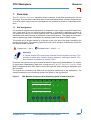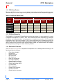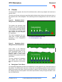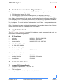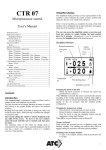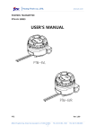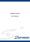
1
CPCI
Backplane
Manual
Manual ID: 24229, Rev. Index 01
March 01, 2002
The products described in this manual
are in compliance with all applied CE
standards.
Preface
CPCI Backplane
Revision History
Manual/Product Title:
Manual ID Number:
Rev.
Index
01
CPCI Backplane Manual
24229
Brief Description of Changes
Initial Issue
Date of Issue
Mar. 01, 2002
Imprint
Copyright © 2002 PEP Modular Computers GmbH. All rights
reserved. This manual may not be copied, photocopied,
reproduced, translated or converted to any electronic or machinereadable form in whole or in part without prior written approval of
PEP Modular Computers GmbH.
DISCLAIMER:
PEP Modular Computers GmbH rejects any liability for the correctness
and completeness of this manual as well as its suitability for any particular purpose.
This manual was realized by: TPD/Engineering, PEP Modular Computers GmbH.
Page ii
© 2002 PEP Modular Computers GmbH
ID 24229, Rev. 01
CPCI Backplane
Preface
Table of Contents
Revision History ........................................................................................................ ii
Imprint ....................................................................................................................... ii
Table of Contents ..................................................................................................... iii
List of Tables ............................................................................................................. v
List of Figures ......................................................................................................... vii
Proprietary Note ....................................................................................................... ix
Trademarks .............................................................................................................. ix
Environmental Protection Statement ........................................................................ ix
Explanation of Symbols ............................................................................................ x
For Your Safety ........................................................................................................ xi
High Voltage Safety Instructions .......................................................................... xi
Special Handling and Unpacking Instructions ..................................................... xi
General Instructions on Usage ............................................................................... xii
Two Year Warranty ................................................................................................. xiii
1.
2.
3.
Overview .......................................................................................................... 3
1.1
Slot Assignment ......................................................................................... 3
1.2
PCB Form Factor ....................................................................................... 4
1.3
PCI Bus Extension ..................................................................................... 4
1.4
Distinctive Features .................................................................................... 4
Clocks .............................................................................................................. 5
2.1
Backplane Clock Skew ............................................................................... 5
2.2
System Slot Board Clock Skew .................................................................. 6
Backplane Interfaces ....................................................................................... 6
3.1
Line Connection ......................................................................................... 6
3.2
Power Supply Connectors .......................................................................... 6
3.3
Signalling Environment ............................................................................. 11
3.4
Rear I/O Connectivity ................................................................................ 11
3.5
Coding Keys ............................................................................................. 12
3.6
Flexible Grounding Option ....................................................................... 13
3.7
Rack Dividers ........................................................................................... 13
4.
PEP CompactPCI Standard Backplanes ....................................................... 14
5.
Product Documentation Organization ............................................................ 15
ID 24229, Rev. 01
© 2002 PEP Modular Computers GmbH
Page iii
Preface
6.
7.
CPCI Backplane
Applied Standards .......................................................................................... 15
6.1
CE Compliance ......................................................................................... 15
6.2
Other Safety Standards ............................................................................ 15
6.3
Mechanical Compliance ............................................................................ 15
6.4
Environmental Tests ................................................................................. 15
Related Publications ...................................................................................... 15
7.1
Page iv
CompactPCI Systems/Boards .................................................................. 15
© 2002 PEP Modular Computers GmbH
ID 24229, Rev. 01
CPCI Backplane
Preface
List of Tables
1
PCB Form Factor [mm] ...................................................................................... 4
2
Pinouts of AC/DC Line Connector ...................................................................... 6
3
Power Supply Connectors ................................................................................. 7
4
DIN M24/8 Connector Pinouts (3U Backplanes) ................................................ 8
5
DIN M24/8 Connector Pinouts (6U Backplanes) ................................................ 9
6
ATX Connector Pinouts .................................................................................... 10
7
PEP CompactPCI Standard Backplane Family ................................................ 14
8
PEP CompactPCI Standard Backplanes – Mechanical Characteristics ........... 14
ID 24229, Rev. 01
© 2002 PEP Modular Computers GmbH
Page v
Preface
CPCI Backplane
This page was intentionally left blank.
Page vi
© 2002 PEP Modular Computers GmbH
ID 24229, Rev. 01
CPCI Backplane
Preface
List of Figures
1
PEP Modular Computers Slot Numbering (both 3U and 6U boards) ................. 3
2
Backplane Clock Assignment (3U backplanes) ................................................. 5
3
Backplane Clock Assignment (6U backplanes) ................................................. 5
4
Orientation and Pinouts of AC/DC Line Connectors .......................................... 6
5
DIN M24/8 Power Supply Connector ................................................................ 7
6
ATX Power Supply Conector on 3U Backplane (left) and 6U Backplanes ....... 10
7
Board/Rack Coding Keys ................................................................................. 12
ID 24229, Rev. 01
© 2002 PEP Modular Computers GmbH
Page vii
Preface
CPCI Backplane
This page was intentionally left blank.
Page viii
© 2002 PEP Modular Computers GmbH
ID 24229, Rev. 01
CPCI Backplane
Preface
Proprietary Note
This document contains information proprietary to PEP Modular Computers. It may not be copied or transmitted by any means, disclosed to others, or stored in any retrieval system or media
without the prior written consent of PEP Modular Computers GmbH or one of its authorized
agents.
The information contained in this document is, to the best of our knowledge, entirely correct.
However, PEP Modular Computers cannot accept liability for any inaccuracies or the consequences thereof, or for any liability arising from the use or application of any circuit, product, or
example shown in this document.
PEP Modular Computers reserves the right to change, modify, or improve this document or the
product described herein, as seen fit by PEP Modular Computers without further notice.
Trademarks
PEP Modular Computers, the PEP logo and, if occurring in this manual, “CXM” are trade marks
owned by PEP Modular Computers GmbH, Kaufbeuren (Germany). In addition, this document
may include names, company logos, and trademarks which are registered trademarks and are,
therefore, proprietary to their respective owners.
Environmental Protection Statement
These products have been manufactured to satisfy environmental protection requirements
where possible. Many of the components used (structural parts, printed circuit boards, connectors, batteries, etc.) are capable of being recycled.
Final disposition of these products after their service life must be accomplished in accordance
with applicable country, state, or local laws or regulations.
ID 24229, Rev. 01
© 2002 PEP Modular Computers GmbH
Page ix
Preface
CPCI Backplane
Explanation of Symbols
CE Conformity
This symbol indicates that the products described in this manual are
in compliance with all applied CE standards. Please refer also to the
section “Applied Standards” in this manual.
Caution, Electric Shock!
This symbol and title warn of hazards due to electrical shocks (> 60V)
when touching products or parts of them. Failure to observe the precautions indicated and/or prescribed by the law may endanger your
life/health and/or result in damage to your material.
Please refer also to the section “High Voltage Safety Instructions” on
the following page.
Warning, ESD Sensitive Device!
This symbol and title inform that electronic boards and their components are sensitive to static electricity. Therefore, care must be taken
during all handling operations and inspections of this product, in
order to ensure product integrity at all times.
Please read also the section “Special Handling and Unpacking
Instructions” on the following page.
Warning!
This symbol and title emphasize points which, if not fully understood
and taken into consideration by the reader, may endanger your health
and/or result in damage to your material.
Note...
This symbol and title emphasize aspects the reader should read
through carefully for his or her own advantage.
Page x
© 2002 PEP Modular Computers GmbH
ID 24229, Rev. 01
CPCI Backplane
Preface
For Your Safety
Your new PEP products have been developed and tested carefully to provide all features necessary to ensure their compliance with electrical safety requirements. They were also designed
for a long fault-free life. However, the life expectancy of your products can be drastically reduced by improper treatment during unpacking and installation. Therefore, in the interest of
your own safety and of the correct operation of your new PEP products, you are requested to
conform with the following guidelines.
High Voltage Safety Instructions
Warning!
All operations on these products must be carried out by sufficiently
skilled personnel only.
Caution, Electric Shock!
Before installing your new PEP products into a system always ensure
that your mains power is switched off. This applies also to the installation of piggybacks.
Serious electrical shock hazards can exist during all installation,
repair and maintenance operations with this product. Therefore,
always unplug the power cable and any other cables which provide
external voltages before performing work.
Special Handling and Unpacking Instructions
ESD Sensitive Device!
Electronic boards and their components are sensitive to static electricity.
Therefore, care must be taken during all handling operations and inspections
of this product, in order to ensure product integrity at all times.
Do not handle these products out of their protective enclosures while they are not used for
operational purposes unless they are otherwise protected.
Whenever possible, unpack or pack these products only at EOS/ESD safe work stations.
Where a safe work station is not guaranteed, it is important for the user to be electrically discharged before touching the products with his/her hands or tools. This is most easily done by
touching a metal part of your system housing.
It is particularly important to observe standard anti-static precautions when changing piggybacks, ROM devices, jumper settings etc. If the products contain batteries for RTC or memory
back-up, ensure that they are not placed on conductive surfaces, including anti-static plastics
or sponges. They can cause short circuits and damage the batteries or conductive circuits.
ID 24229, Rev. 01
© 2002 PEP Modular Computers GmbH
Page xi
Preface
CPCI Backplane
General Instructions on Usage
In order to maintain PEP’s product warranty, these products must not be altered or modified in
any way. Changes or modifications to these products which are not explicitly approved by PEP
Modular Computers and described in this manual or received from PEP Technical Support as
a special handling instruction will void your warranty.
These products should only be installed in or connected to systems that fulfill all necessary
technical and specific environmental requirements. This applies also to the operational temperature range of the specific product version which must not be exceeded. If batteries are present
their temperature restrictions must be taken into account.
In performing all necessary installation and application operations, please follow only the instructions supplied by the present manual.
Keep all the original packaging material for future storage or warranty shipments. If it is necessary to store or ship the board please re-pack it as nearly as possible in the manner in which it
was delivered.
Special care is necessary when handling or unpacking the product. Please, consult the special
handling and unpacking instruction on the previous page of this manual.
Page xii
© 2002 PEP Modular Computers GmbH
ID 24229, Rev. 01
CPCI Backplane
Preface
Two Year Warranty
PEP Modular Computers grants the original purchaser of PEP products a TWO YEAR LIMITED
HARDWARE WARRANTY as described in the following. However, no other warranties that may be
granted or implied by anyone on behalf of PEP are valid unless the consumer has the express
written consent of PEP Modular Computers.
PEP Modular Computers warrants their own products, excluding software, to be free from manufacturing and material defects for a period of 24 consecutive months from the date of purchase. This warranty is not transferable nor extendible to cover any other users or long-term
storage of the product. It does not cover products which have been modified, altered or repaired by any other party than PEP Modular Computers or their authorized agents. Furthermore, any product which has been, or is suspected of being damaged as a result of negligence,
improper use, incorrect handling, servicing or maintenance, or which has been damaged as a
result of excessive current/voltage or temperature, or which has had its serial number(s), any
other markings or parts thereof altered, defaced or removed will also be excluded from this warranty.
If the customer’s eligibility for warranty has not been voided, in the event of any claim, he may
return the product at the earliest possible convenience to the original place of purchase, together with a copy of the original document of purchase, a full description of the application the
product is used on and a description of the defect. Pack the product in such a way as to ensure
safe transportation (see our safety instructions).
PEP provides for repair or replacement of any part, assembly or sub-assembly at their own discretion, or to refund the original cost of purchase, if appropriate. In the event of repair, refunding
or replacement of any part, the ownership of the removed or replaced parts reverts to PEP
Modular Computers, and the remaining part of the original guarantee, or any new guarantee to
cover the repaired or replaced items, will be transferred to cover the new or repaired items. Any
extensions to the original guarantee are considered gestures of goodwill, and will be defined in
the “Repair Report” issued by PEP with the repaired or replaced item.
PEP Modular Computers will not accept liability for any further claims resulting directly or indirectly from any warranty claim, other than the above specified repair, replacement or refunding.
In particular, all claims for damage to any system or process in which the product was employed, or any loss incurred as a result of the product not functioning at any given time, are
excluded. The extent of PEP Modular Computers liability to the customer shall not exceed the
original purchase price of the item for which the claim exists.
PEP Modular Computers issues no warranty or representation, either explicit or implicit, with
respect to its products’ reliability, fitness, quality, marketability or ability to fulfil any particular
application or purpose. As a result, the products are sold “as is,” and the responsibility to ensure
their suitability for any given task remains that of the purchaser. In no event will PEP be liable
for direct, indirect or consequential damages resulting from the use of our hardware or software
products, or documentation, even if PEP were advised of the possibility of such claims prior to
the purchase of the product or during any period since the date of its purchase.
Please remember that no PEP Modular Computers employee, dealer or agent is authorized to
make any modification or addition to the above specified terms, either verbally or in any other
form, written or electronically transmitted, without the company’s consent.
ID 24229, Rev. 01
© 2002 PEP Modular Computers GmbH
Page xiii
Preface
CPCI Backplane
This page was intentionally left blank.
Page xiv
© 2002 PEP Modular Computers GmbH
ID 24229, Rev. 01
CPCI Backplane
General
General
ID 24229, Rev. 01
© 2002 PEP Modular Computers GmbH
Page 1
General
CPCI Backplane
This page was intentionally left blank.
Page 2
© 2002 PEP Modular Computers GmbH
ID 24229, Rev. 01
CPCI Backplane
General
1. Overview
The PEP Modular Computers' backplane family includes 4, 6 and 8-slot boards both in 3U and
6U format. They can be provided with either a standard DIN M-series, a Faston plug/M4 screw
or an ATX power supply connector. Backplanes are available as 32-bit or 64-bit implementations.
1.1 Slot Assignment
A CompactPCI system board (backplane) is composed of up to eight CompactPCI board locations (slots) with 20.32 mm center-to-center spacing. A CompactPCI backplane consists of
one system slot and up to seven peripheral slots. The system slot provides arbitration, clock
distribution and reset functions for all boards connected to the bus. The system slot is responsible for performing system initialization by managing each local board's IDSEL signal.
The system slot is always marked by a triangle on the front side of the board containing the
physical slot number. The following symbols provide visual indication of backplane connector
and adapter board capability:
System slot — slot 1;
Peripheral slot — slots 2 ... n.
Warning!
A system master CPU should be inserted into the system slot only. The
peripheral slots may contain simple adapters, intelligent slaves, PCI
bus masters or peripheral master CPU's.
Physically, the system slot may be located at the left or right end of the backplane. For simplicity and system expandability (heat-sink, cooling fan etc.), all PEP Modular Computers CompactPCI backplanes have their system slots at the right end when viewing the backplane from
the front side.
The logical slot numbering may differ from the physical numbering on the backplanes. The
relation between the two numbering systems are shown in the figure below.
Figure 1:
PEP Modular Computers Slot Numbering (both 3U and 6U boards)
Physical slot numbering:
8
7
6
5
4
3
2
1
6
7
8
Logical slot numbering:
1
ID 24229, Rev. 01
2
3
4
5
© 2002 PEP Modular Computers GmbH
Page 3
General
CPCI Backplane
1.2 PCB Form Factor
The size of PEP Modular Computers backplanes is based upon the Eurocard industry standard and depends on their height format (3U/6U), their number of slots and power supply unit.
Table 1: PCB Form Factor [mm]
Slot Number/
PSU
3U
6U
DIN MSeries
Faston/M4
ATX
DIN MSeries
Faston/M4
ATX
4-Slot
80.28*128.7
100.7*128.7
—
—
—
—
6-Slot
—
120.7*128.7
131.5*128.7
—
—
—
8-Slot
—
197.12*128.7
—
—
222.52*262.05
—
11-Slot
—
283.0*128.7
—
—
—
—
1.3 PCI Bus Extension
The PICMG 2.0 CompactPCI Specification restricts the length of a bus segment of a given
CompactPCI backplane to 8 slots or less. This restriction has been determined by extensive
simulation and characterization and guarantees an optmimum operation of PCI-compliant
integrated circuits. Since the inception of PCI, design engineers have extended this eight-slot
restriction by using PCI-to-PCI bridge components. Thanks to the use of such bridge components, which are put into effect on a special bridge module, the implementation of CompactPCI backplanes providing more than 8 slots is possible.
1.4 Distinctive Features
The PEP Modular Computers CompactPCI backplanes can be distinguished according to the
following distinctive features:
•
•
•
•
•
•
•
•
•
•
•
•
•
•
•
Form factor (height)
Dimensions
Number of slots
Bus resolution
Bus frequency
Rear I/O connectivity
Hot-swap capability
Power Supply Connector
Redundant power supply
Flexible grounding option
Fan connector
Drive connector
Power LED Connector
PS-ON Connector
Reset function connector
Page 4
© 2002 PEP Modular Computers GmbH
ID 24229, Rev. 01
CPCI Backplane
General
2. Clocks
The CompactPCI system slot drives five buffered clocks, while every adapter slot receives its
specific clock.
The 6-slot and 8-slot versions are provided with individual clock timings for the three slots on
the opposite end of the backplane. The remaining slots are assigned one clock for each two
slots.
Figure 2: Backplane Clock
Assignment (3U backplanes)
The system slot provides clock
signals for all the PCI peripherals
in the system, including devices
on the system slot board. Peripheral boards are provided with
clock signals via the CompactPCI backplane.
The 8-slot backplanes are provided with a diode termination
according to the CompactPCI
Specification.
Clock numbering:
1
2
3
4*
5**
* 6-slot/8-slot backplanes only
** 8-slot backplanes only
Figure 3: Backplane Clock
Assignment (6U backplanes)
Clock skew is the difference
between the maximum and minimum propagation delay of any
PCI clock signal. There are two
different types of clock skew:
backplane and system slot board
clock skew.
Clock numbering:
1
2
3
4
5
6
7
The two concepts of backplane
and system slot board clock
skew are explained in the following.
2.1 Backplane Clock Skew
A CompactPCI backplane provides the distribution of clock signals for all of the board slots in
the system. The differences in the trace routing and net topologies contribute to skew and also
define the longest clock delay. Particular attention is paid by the PEP Modular Computers system design to meet overall system clock skew requirements namely through simulation, testing, and qualification.
ID 24229, Rev. 01
© 2002 PEP Modular Computers GmbH
Page 5
General
CPCI Backplane
2.2 System Slot Board Clock Skew
This is the clock skew that may be attributed to the onboard routing differences (if any) of all of
the PCI clocks as well as the skew specification for the type of integrated circuit driver used for
clock distribution. The onboard clock routing is designed to complement the propagation
delays of distributing the clock to a backplane and still meet overall system skew requirements.
3. Backplane Interfaces
3.1 Line Connection
Both AC and DC power supply to most backplanes are connected by means of 3-pole MateN-Lok connectors marked ”LINE1” and, on some 6U backplanes, “LINE2” on the backplane
reverse side.
Figure 4:
Orientation and Pinouts of AC/DC Line Connectors
Table 2: Pinouts of AC/DC Line Connector
1
Pin
2
3
AC
DC
1
N
- DC supply
2
L
+ DC supply
3
PE
PE
Attention!
AC/DC power supply units must be installed only with backplanes/systems connected to an AC power line and DC/DC power supply units
with backplanes/systems connected only to a DC power line.
Failure to comply with this warning will result in damage to your equipment.
3.2 Power Supply Connectors
The AC or DC input voltages to the power supply unit and the Vo1...Vo4 output voltages from
the power supply unit to the backplane are connected via a power supply connector complying with one of the below described specifications.
Note...
The term ”power supply connector” is used both for the connectors
receiving the backplanes’ power supply and the mating output connectors of the power supply units.
Page 6
© 2002 PEP Modular Computers GmbH
ID 24229, Rev. 01
CPCI Backplane
General
Table 3: Power Supply Connectors
Connector Type
DIN M-Series
Faston/M4
ATX
Description
3 or 4-pole DIN M-series female power supply connectors for power
throughput to the power supply unit and a 30- (32-) pole DIN M24/8 female
power supply connector for power reception from the power supply unit
(DIN 41612)
M4 screw connection combined with 6.3mm*0.8mm strip connectors.
Male 20-pole ATX connector for power supply from the reverse side of the
backplane; the ATX PSUs available on the market are provided with a
matching connector.
The pinouts of the DIN M24/8 and of the ATX power supply connectors are illustrated below.
Note...
As the overall pinout of the DIN M24/8 connector installed on a 3U
backplane is identical to that of both DIN M24/8 connectors installed
on a 6U backplane taken together, on a 6U backplane some functions
are connected on the upper or on the lower connector only and, therefore, are not connected on the other connector (see tables below).
Figure 5:DIN M24/8 Power Supply
Connector
Warning!
25
22
20
...
13
11
5
2
ID 24229, Rev. 01
22 C B A
20
...
13
11
© 2002 PEP Modular Computers GmbH
Please note that the
pinouts of the DIN
M24/8 power supply
connectors of various
power supply units differ. Therefore, please
refer also to the pinout
tables of the single
power supply units for
any possible differences to the pinouts
supplied in the tables
below.
Page 7
General
CPCI Backplane
Table 4: DIN M24/8 Connector Pinouts (3U Backplanes)
Pin
Function
Pin
Function
2
L1
B.16
+3.3VL
5
N
B.17
+3.3VL
8
N/C
B.18
+3.3VL
11
PE
B.19
+12VL
A.13
INT
B.20
-12VL
A.14
INH
C.13
EN
A.15
INT
C.14
DEG
A.16
OVF
C.15
INT
A.17
+5VF
C.16
+3.3VL
A.18
+3.3VL
C.17
+3.3VL
A.19
+12VL
C.18
+3.3VL
A.20
-12VL
C.19
+12VL
B.13
+3.3VL
C.20
-12VL
B.14
+3.3VL
22
+5VL
B.15
+3.3VL
25
OVL
L1 = live connection, N = neutral, PE = earth protection; INT = internally connected; N/C = not connected.
Warning!
To ensure correct 5V operation of your equipment it is necessary to
connect 5VL to 5VF and 0VL to 0VF.
The maximum voltage compensation is 0.25V per line.
Page 8
© 2002 PEP Modular Computers GmbH
ID 24229, Rev. 01
CPCI Backplane
General
Table 5: DIN M24/8 Connector Pinouts (6U Backplanes)
Function
Pin
Lower
Connector
Upper
Connector
Function
Pin
Lower
Connector
Upper
Connector
2
L1
N/C
B.16
+3.3VL
+3.3VL
5
N
N/C
B.17
+3.3VL
+3.3VL
8
N/C
N/C
B.18
+3.3VL
+3.3VL
11
PE
N/C
B.19
N/C
+12VL
A.13
N/C
N/C
B.20
N/C
-12VL
A.14
INH
N/C
C.13
EN
N/C
A.15
N/C
N/C
C.14
DEG
N/C
A.16
N/C
N/C
C.15
INT
N/C
A.17
N/C
N/C
C.16
+3.3VL
+3.3VL
A.18
+3.3VL
+3.3VL
C.17
+3.3VL
+3.3VL
A.19
N/C
+12VL
C.18
+3.3VL
+3.3VL
A.20
N/C
-12VL
C.19
N/C
+12VL
B.13
+3.3VL
+3.3VL
C.20
N/C
-12VL
B.14
+3.3VL
+3.3VL
22
N/C
+5VL
B.15
+3.3VL
+3.3VF
25
OVL
OVL
L1 = live connection, N = neutral, PE = earth protection; INT = internally connected; N/C = not connected.
Warning!
To ensure correct 5V operation of your equipment it is necessary to
connect 5VL to 5VF and 0VL to 0VF.
The maximum voltage compensation is 0.25V per line.
ID 24229, Rev. 01
© 2002 PEP Modular Computers GmbH
Page 9
General
CPCI Backplane
Figure 6: ATX Power Supply Conector on 3U Backplane (left) and 6U
Backplanes (optional, right)
10
20
11
1
1
11
20
10
Table 6: ATX Connector Pinouts
Pin
Function
Pin
Function
1
+3.3V
11
+3.3V
2
+3.3V
12
-12V
3
GND
13
GND
4
+5V
14
PS-ON
5
GND
15
GND
6
+5V
16
GND
7
GND
17
GND
8
PW-OK
18
-5V
9
+5V SB
19
+5V
10
+12V
20
+5V
Page 10
© 2002 PEP Modular Computers GmbH
ID 24229, Rev. 01
CPCI Backplane
General
3.3 Signalling Environment
Each CompactPCI backplane supports a 5V or a 3.3V signaling environment (VIO), and PCI
allows for two types of buffer interfaces for interboard connection. However, a gradual shift to
3.3V is occurring as the semiconductor industry shifts to the lower power interface for speed
and power dissipation reasons. For this reason, the PEP Modular Computers system backplanes are also designed for 3.3V usage.
Warning!
Using both 3.3V and 5V boards within the same system may result in
damage to your equipment. Please note that the presence of only one
5V board determines a 5V signalling environment. The default setting
is 5V.
When changing the signalling environment from 5V to 3.3V or viceversa, please make sure that coding keys of the appropriate color are
used (see Coding Keys section of this chapter).
3.4 Rear I/O Connectivity
According to PICMC CompactPCI Specification, V. 2.0, R. 3.0, standard rear I/O connectivity
is provided on the P3 backplane connector. The standard rear I/O pinouts of the P3 connector
are shown in the Overview chapter of this manual.
In addition, board-specific rear I/O connectivity can be provided on one or more of the backplane connectors P2, P4, P5. For the pinouts of any board-specific rear I/O connectors please
refer to the User’s Manual of the relating board.
ID 24229, Rev. 01
© 2002 PEP Modular Computers GmbH
Page 11
General
CPCI Backplane
3.5 Coding Keys
Figure 7:
Keys
Board/Rack Coding
PCI Connectors
P1 and P4
PEP Modular Computers Compact-PCI
systems present an advantage in the
form of a special combination of coding
keys. They ensure proper mating of
boards and backplanes in terms of voltage and function. For this purpose, two
different kinds of coding keys have
been devised, which are described in
the following.
Additional Board Coding Key
No key: universal signalling
Yellow: 3.3 V (NCR)
Blue: 5.0 V
Red: H110 present
P4
Main Board Keying
Proper board installation is ensured by
the use of colored coding keys for 3.3V
(yellow) or 5V (blue) operation, thus
preventing incorrect installation of
adapter boards. This facility also prevents confusion when hot-swapping
boards.
Additional Board Keying
The function of the additional board
coding key depends on the backplane.
Backplanes equipped with an H110
telephony connector are marked with a
red H110 key. Dual-PCI backplanes use
coding keys for 3.3V (yellow) or 5V
(blue) operation of the upper PCI bus.
AC/DC Keying
To ensure proper connection in terms of
AC/DC power, all PEP Modular Computers power supply units are provided
with special AC/DC coding keys.
Main Board Coding Key
No key: universal signalling
Yellow: 3.3 V (NCR)
Blue: 5.0 V
P1
The coding standard is not fully defined
at the moment of writing. It will be
implemented as soon as available.
Rack Keying
Rack Coding Keys
Red
Boards must be fitted into a CompactPCI backplane in a certain order,
depending on whether they are bus
master boards or I/O boards. To this end, special asymmetrically shaped coding keys can be
used by the customer to ensure that the boards are inserted properly.
Page 12
© 2002 PEP Modular Computers GmbH
ID 24229, Rev. 01
CPCI Backplane
General
3.6 Flexible Grounding Option
With certain backplane types it is possible to select electrical isolation or connection between
the bus GND and the backpanel support PE (rack), thanks to the fact that every second fastening hole of backplanes is non-conducting. If only these fastening holes are used, there is
no electrical connection between GND and PE on the system bus. If additional holes are
used, a multi-point connection is created such as may be required for EMI protection purposes.
3.7 Rack Dividers
3U boards may be used in a 6U rack. If one or two 3U backplanes are used, a middle bar is
used to hold the 3U boards in place. If the 3U boards are installed on a 6U backplane, a split
kit must be used in place of the backplane’s P3 connector(s). For further details on split kit and
middle bar separation, please refer to the Racks chapter of this manual.
ID 24229, Rev. 01
© 2002 PEP Modular Computers GmbH
Page 13
General
CPCI Backplane
4. PEP CompactPCI Standard Backplanes
Table 7: PEP CompactPCI Standard Backplane Family
Form Factor
Slots*
Power Supply Connector
Backplane
Faston plugs/M4 Screw-Type
CP3-BP4
DIN M-Series
CP3-BP4-M
ATX
CP3-BP6-ATX
DIN M-Series
CP3-BP8-M
DIN M-Series
CP3-BP8-RIO
11
DIN M-Series
CP3-BP11-M
8
DIN M-Series
CP6-BP8-STD
8/15**
DIN M-Series
CP6-BP8-DUALPCI
8
DIN M-Series
CP6-BP8-H110
4
3U
6
8
6U
* System slot on all backplanes on the right.
** 8 6U slots or down to 1 6U slot in combination with up to 14 3U slots.
Table 8: PEP CompactPCI Standard Backplanes – Mechanical Characteristics
Backplane
Special Features
Size
Weight
CP3-BP4
—
80.3*128.7 mm
170g
CP3-BP4-M
—
100.7*128.7 mm
165g
CP3-BP6-ATX
Rear I/O connectivity
120.7*128.7 mm
270g
CP3-BP8-M
Rear I/O connectivity
197.1*128.7 mm
400g
CP3-BP8-RIO
Rear I/O connectivity
197.1*128.7 mm
440g
CP3-BP11-M
Rear I/O connectivity
283.0*128.7 mm
700g
CP6-BP8-STD
Rear I/O connectivity,
hot-swap capability
222.5*262.0 mm
1,000g
CP6-BP8-DUALPCI
Dual PCI,
hot-swap capability
222.5*262.0 mm
960g
CP6-BP8-H110
H.110
222.5*262.0 mm
980g
* System slot on all backplanes on the right.
** 8 6U slots or down to 1 6U slot in combination with up to 14 3U slots.
Page 14
© 2002 PEP Modular Computers GmbH
ID 24229, Rev. 01
CPCI Backplane
General
5. Product Documentation Organization
The product documentation organization for PEP’s CPCI Power Supplies is as follows:
1. CPCI Backplane Manual (ID: 24229)
2. CPCI Backplane Product Documentation Guide (ID: 24229, Sub-ID: PDG)
3. Specific PEP CPCI Backplane Product Documentation (ID: 24229, Sub-ID: PDnn)
Item 1 above is represented by this manual which provides generic information about PEP’s
CPCI backplanes. Item 2 is enclosed with this manual for referencing to applicable CPCI Backplane Product Documentation. Item 3 represents the individual product documentation for specific backplanes. For each backplane addressed in item 2 there is a separate document
available.
Each of the above items are maintained independently of one another, whereby item 2 always
reflects the current status of available product documentation.
6. Applied Standards
The PEP Modular Computers' CompactPCI backplanes comply where applicable with the
requirements of the following standards.
6.1 CE Compliance
•
•
•
Emission
Immission
Electrical Safety
EN50081-1, EN 55011/EN 55022
EN50082-2, EN 61000-4
EN60950, VDE 0100, VDE 0805
6.2 Other Safety Standards
•
UL, CSA, DVE, NEMKO
6.3 Mechanical Compliance
•
Mechanical Dimensions
IEEE 1101.10
6.4 Environmental Tests
•
•
•
•
Vibration/Broad-Band
Random Vibration
Permanent Shock
Single Shock
IEC68-2-6
IEC68-2-64 (3U boards)
IEC68-2-29
IEC68-2-27
7. Related Publications
7.1 CompactPCI Systems/Boards
•
•
•
•
CompactPCI Specification, V. 2.0, Rev. 2.1
DIN 41612
ATX Specification
CompactPCI Power Interface Specification, 2.11 R1.0
ID 24229, Rev. 01
© 2002 PEP Modular Computers GmbH
Page 15