1
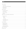
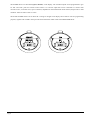
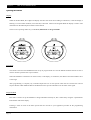
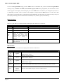
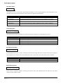
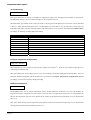
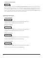
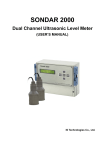
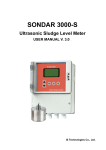
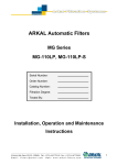
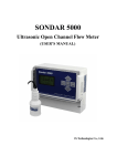
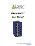
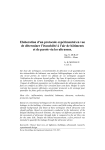
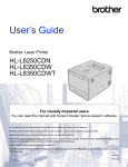
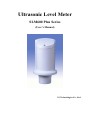
Ultrasonic Level Meter
SLM600 Plus Series
(User’s Manual)
IS Technoloigies Co., Ltd.
November 2000
COPYRIGHT
© IS Technologies Co., Ltd. All rights reserved. No part of this publication may be reproduced, transmitted, transcribed,
stored in a retrieval system, or translated into any language in any form without the written permission of IS
Technologies Co., Ltd.
WARRANTY AND LIABILITY
IS Technologies Co., Ltd. guarantees for a period of 1 year from the date of delivery that it will either exchange or
repair any part of this product returned to IS Technologies Co., Ltd. if it is found to be defective in material or
workmanship, subject to the defect not being due to unfair wear and tear, misuse, modification or alteration, accident,
misapplication or negligence.
DISCLAIMER
IS Technologies neither gives nor implies any process guarantee for this product, and shall have no liability in respect
of any loss, injury or damage whatsoever arising out of the application or use of any product or circuit described herein.
Every effort has been made to ensure accuracy of this documentation, but IS Technologies cannot be held liable for any
errors.
TECHNICAL ENQUIRIES
Please contact IS Technologies Co., Ltd. for technical support.
COMMENTS AND SUGGESTIONS
If you have any comments or suggestions about this product, then please contact:
IS Technologies Co., Ltd.
203/504 Buchon Techno Park, 192
Yakdae Dong, Wonmi Gu
Buchon City Kyungki Korea
Tel: 82-32-621 2606
Fax: 82-32-621 2612
Web Site: http://www.istec21.com
e-mail: [email protected]
Contents
Chapter 1 Start Here…............................................................................................................................................................................... 4
About this Manual......................................................................................................................................................................................4
About the SLM 600 Level Monitoring System.......................................................................................................................................5
Functional Description...............................................................................................................................................................................5
Product Specification.................................................................................................................................................................................7
Chapter 2 Installation ................................................................................................................................................................................. 8
Power Supply Requirements .....................................................................................................................................................................8
Terminal Connections............................................................................................................................................................................. 11
Preparation for Operation ....................................................................................................................................................................... 12
Maintenance ............................................................................................................................................................................................ 12
Chapter 3 How To Use Your SLM 600 Level Monitoring System ....................................................................................................... 13
Operating the Controls............................................................................................................................................................................ 13
Display............................................................................................................................................................................................... 13
Run Mode.......................................................................................................................................................................................... 13
Program Mode .................................................................................................................................................................................. 13
How to Access Program Mode .............................................................................................................................................................. 14
What to Do First................................................................................................................................................................................ 15
Chapter 4 Menu Guide............................................................................................................................................................................. 16
Application Menu Options ..................................................................................................................................................................... 16
Process Menu Options ............................................................................................................................................................................ 17
Compensation Menu Options................................................................................................................................................................. 18
Switched Outputs Menu Options ........................................................................................................................................................... 19
Chapter 5 Troubleshooting ...................................................................................................................................................................... 20
Menu Option Record............................................................................................................................................................................... 21
Chapter 1
Start Here…
Congratulations on your purchase of a Sondar Ultrasonic Level Meter 600 Series. This quality system has been
developed over many years and represents the latest in high technology ultrasonic level measurement and control.
It has been designed to give you years of trouble-free performance, and a few minutes spent reading this operating
manual will ensure that your installation is as simple as possible.
About this Manual
It is important that this manual is referred to for correct installation and operation. There are various parts of the manual
that offer additional help or information as shown:
Tips
TIP
At various parts of this manual you will find tips to help you.
Additional Information
Additional Information
At various parts of the manual, you will find
sections like this that explain specific items in
more detail.
Page 4
About the SLM600 Series
Functional Description
The Sondar SLM600 Series is a highly developed ultrasonic level measurement system which provides non-contacting
level measurement for a wide variety of applications in both liquids and solids.
Easy calibration and maintenance free “fit and forget” performance mean that you can install the SLM600 Series rapidly
and with confidence. Two Switched outputs NPN open collector, with fully programmable setpoints are provided in
the 3 wire version, together with fault condition being indicated by the mA output on both the 2 and 3 wire versions.
The Sondar SLM600 Series operates on the principle of timing the echo received from a measured pulse of sound
transmitted in air and utilise “state of the art” echo extraction technology.
It can measure distances from 0.35m to 6m from the face of the transducer to the surface being monitored, dependent on
the material being measured.
Page 5
The SLM600 Series can show level, space, distance, on the display. The switched outputs can be programmed to give
an ‘ON’ and ‘OFF’ point for external control. There is a 4-20 mA output that can be connected to a remote chart
recorder or PLC, to monitor level, space or distance, dependant on the measurement mode selected, and provides a ‘fault
condition’ alarm of either 3.8mA or 21mA.
The Sondar SLM600 Series has an IP65 lid covering an integral LCD display and 4 buttons used for programming
purposes, together with 4 LED’s which provide status information whilst in RUN and PROGRAM Mode.
Page 6
Product Specification
Physical
Dimensions
overall
105 (dia). x 248.5 (height) mm
electronics housing
105 (dia). x 172 (height) mm
transducer housing
55 (dia) x 76.5 (height) mm
mounting
2” NPT
Weight
Nominal 1.5 kg
Case material/description
Polypropylene
Cable entry detail
1 x PG9 at rear (fitted with gland)
Environmental
IP Rating (electronics housing)
IP65
Max. & Min. temperature (electronics)
-20 ºC to +70 ºC (-4 ~ 158°F)
Pressure
up to 2 Bar
CE approval
EMC approval to BS EN 55011:1991 (Class A),.
BS EN50082-2: 1995
BS EN61000-4-2:1995
BS ENV50140:1993
BS ENV50141:1993
BS ENV50204:1995
BS EN61000-4-4:1995
Performance
Accuracy
0.25% of the measured range or
3 mm (whichever is greater)
Resolution
0.03% of full scale or 1mm (whichever is greater)
Max. range
Liquids 256 inches
Min. range
14 inches
Beam Angle
13o at -3dB.
Damping Rate
Adjustable 0.35f/min to 350f/min
Temperature Compensation
Fully compensated via integral temperature sensor over entire operational
span
Outputs
Analogue output
4-20 mA into max 750Ω (user adjustable) Fault condition Alarm 3.8mA or
21mA user selectable.
NPN Open Collector switched output
2 Switched outputs, user programmable setpoints.
Display
3 Digit LCD Display
Programming
On-board programming
via 4 tactile push button keys
Supply
Power supply
DC 20 - 30V
Current Consumption
Less than 0.08A
Page 7
Chapter 2
Installation
Power Supply Requirements
The SLM600 operates from a DC supply of 20 –30V and will typically draw less than 0.08A.
All electronic products are susceptible to electrostatic shock, so follow proper grounding
procedures during installation.
The compact one-piece construction of the SLM600 can be mounted easily using the integral nose thread
(2”NPT or 2” PF).
When choosing a location to mount the SLM600, bear in mind the following:
• For easy access to the LCD display and programming buttons mount it where it is easily accessible.
• The ultrasonic signal path should be free of falling material and obstructions such as pipes, beams etc.
• The SLM600 should be mounted at least 1.15feet above the maximum level of the material and be
perpendicular to the surface.
• The mounting surface should be vibration-free.
• The ambient temperature is between -4°F to 158°F
• There should be no high voltage cables or electrical inverters close by.
• Do not use any metal substances when installing
(Please use the PVC nut & flange supplied as option)
Dimensions
The dimensions of the SLM600 are as shown below
7 c a b le
T h re a d
2 " N P T ,P F
2"
m o u n t in g
Page 8
Outdoor and Open Vessel Installation
The SLM600 can be simply mounted on a bracket, suitable for the application and secured using the thread located at
the top of the transducer (2”NPT).
Care should be taken to ensure that the SLM600 is not installed in direct sunlight, in order to avoid errors in the
measurement of ambient temperature.
Attention should also be taken, when mounting the unit, to ensure that strong windy conditions are avoided, wherever
possible, to prevent abnormal operation.
Bracket
35 cm
Minimum
Nut
Closed Vessel Installation
The SLM600 can be simply screwed into a flange and secured using the thread located at the top of the transducer
(2”NPT).
Where possible use a flange made of a synthetic material such as PVC, to avoid vibration
Place a rubber gasket between the flange of the Sondar and the connection to the vessel to avoid vibration.
Page 9
Stand Pipe Installations
When mounting the SLM600 to a standpipe care should be taken to ensure that the standpipe is of sufficient dia with
reference to its length, see the table below for details:
L(mm)
D (mm)
Length (mm)
80
220
100
280
150
420
200
560
D(mm)
When using a standpipe, fixed to the top of a vessel, ensure that the open end of the standpipe is clear of any
obstructions such as weld seams, gaskets etc. in order to avoid unwanted signal returns.
If using standpipes, which extend into the vessel, beyond the blanking distance, but not as far as the empty level, then
the open end of the standpipe should be cut to an angle of 45o.
The maximum
Pipe should be free
Incorrect
level (100% of
of obstructions
Standpipe
Span) is inside the
such as weld seams
size
Blanking Distance
Page 10
Cable Entry
The SLM600 Series has a single PG11 cable entry, fitted with a suitable gland, to ensure moisture protection is
maintained.
Terminal Connection Details
The SLM600 Series comes in both 2 wire and 3 wire versions the terminal connections for both are as detailed below.
Wiring details are also given on the terminals under the access cover.
3 Wire
2 Wire
V+
Io
V+
Terminal Connections
2 Wire(SLM600B)
♦
V+: Direct Current (DC) input terminal (20-30VDC)
♦
Io: Current Output terminal (4-20mA)
3 Wire(SLM600A)
♦
V+: Direct Current (DC) input terminal (20-30VDC)
♦
COM: DC COMMON input terminal, and also
used as RETURN terminal for all OUTPUTS
♦
Io: Current Output terminal (4-20mA)
♦
L1: Limit 1 Switched Output terminal (NPN Open Collector)
♦
L2: Limit 2 Switched Output terminal (NPN Open Collector)
♦
DET : Service use only
Page 11
COM
Io
L1
L2
DET
Important Information
If the equipment is installed or used in a manner not specified in this
manual, then the protection provided by the equipment may be
impaired.
Preparation for Operation
Before switching on, check the following:
9 The SLM600 is mounted correctly.
9 The power supply is correctly installed.
Maintenance
There are no user serviceable parts inside your SLM600, if you experience any problems with the unit, then please
contact IS Technologies Co., Ltd. for advice.
To clean the equipment, wipe with a damp cloth. Do not use any solvents on the enclosure.
Page 12
Chapter 3
How To Use SLM600 Series
Operating the Controls
Display
Whilst in the Run Mode, the 3-digit LCD display will show the current level reading in centimetres, it will also display a
flashing “0” when a fault condition (Loss Of Echo) is detected. When in the Program Mode the display is used to read
information on the Menu Options and the values entered.
There are two operating modes for your SLM600, Run Mode and Program Mode.
Run Mode
This mode is used once the SLM600 has been set up in program mode. It is also the default mode that the unit reverts to
when it resumes operation after a power failure.
When the SLM600 is switched on for the first time, it will display, in centimetres, the distance from the transducer face
to the target.
After programming is complete, any switched outputs that are set will operate when the level reaches the relevant
setpoint. Whilst in Run Mode the Detect and Distance LED’s provide information on the status of the signal.
Program Mode
This mode is used to set up the SLM600 or change information already set, this is achieved by using the 4 push buttons
located either side of the display.
Entering a value for each of the menu options that are relevant to your application provides all the programming
information.
Page 13
How to Access Program Mode
To access the Program Mode simply press the “Mode” button. Confirmation that you have entered the Program Mode
will be given by the Detect and Mode (Level, Distance, Space) LED’s being extinguished, and the Software Version
will also appear in the display. Each subsequent press of the Mode button will advance you through the options, 01 to
17 (depending on model), values of which can be changed by using the Up and Down buttons. To return to the Run
mode simply press the Run button, confirmation that the SLM600 has returned to Run successfully will be given by the
LCD display indicating the level and the Detect and Mode (Level, Distance, Space) LED flashing.
Button Functions
There are 4 push buttons, 2 located each side of the display their functions are as follows:
Button
Mode
Run
Run Mode
Program Mode
Access Program Mode
Advance through Menu Options
Not used
Return SLM600 to Run Mode
Displays measured level in
inches. Eg. Reading in Run
indicates 250 inches, when
button pressed 503 displayed this
indicates
that
reading
is
2503mm.
Increase Menu Option value
Reads Current Temperature N.B.
–20oC displayed as 020 +20oC
displayed as 20
Decrease Menu Option value
LED Functions
There are 4 LED’s, located above the display their functions are as follows:
LED
Page 14
Condition
Detect
&
Level
Detect
&
Distance
Detect
&
Space
Flashing
together
Detect
Flashing alone
None
All Off
Display
indicates
flashing “0”
Flashing
together
Flashing
together
Function
Indicates Normal Operation
Mode selected = Level
Indicates Normal Operation
Mode selected = Distance
Indicates Normal Operation
Mode selected = Space
Indicates that SLM600 is detecting an echo but checking if the value is correct.
Indicates that SLM600 has gone into Fail condition (LOE).
What to Do First
When you first switch the SLM600 on, it will be reading the distance from the face of the transducer to the surface in
centimetres, as shown on the display.
TIP
In some applications it is simplest to empty the vessel, take a reading
from the SLM600 for distance and then setup the empty level to this
figure.
Once you are satisfied with the installation, and the SLM600 is reading what you would expect in terms of distance
from the face of the transducer to the material level, then you can set up the options as detailed in Chapter 4 Menu
Guide.
Page 15
Chapter 4
Menu Guide
This chapter describes all of the menu options in your SLM600, in numerical order.
Application Menu Options
01 Operating Mode
Factory Set = 1 Level
This option sets the mode of operation when in run mode, and can be set to one of the following:
Option
Description
1= Level
Display shows how full the vessel is with respect to the Empty (0% of Span)
2= Distance
Display shows the distance from the transducer face to the surface.
3= Space
Display shows how an empty vessel is with respect to Full (100% of Span) i.e. how
much space is available in the vessel.
02 Empty Level
Factory Set = 256
This option is to sets the maximum distance from the face of the transducer to the empty point, in inches.
03 4 mA Setpoint
Factory Set = 0
This option sets the distance (or level or space, depending on the selected Operating Mode (Option 01) at which the
4mA output will occur. By default 4mA will represent Empty (0% of Span)
04 20 mA Setpoint
Factory Set = Span
This option sets the distance (or level or space, depending on the selected Operating Mode (Option 01) at which the
20mA output will occur. By default 20mA will represent Full (100% of Span)
Important Information
The Span is the maximum working distance from Empty (0%) to
Full (100%), and is automatically calculated as Empty Level
(Option 02) minus Blanking Distance (Option 05). Except for when
Operating Mode (Option 01) = Distance in this case the Span is
the same as the Empty Level (Option 02)
05 Blanking Distance
Factory Set = 14
This option is the distance from the face of the transducer that is not capable of being measured, and is pre-set to 14
inches. It should not be set to less than this figure, but can be increased if required.
Page 16
Process Menu Options
06 Output Power
Factory Set = 3
This option is used to set the power output from the transducer to suit varying applications.. By reducing the power
emitted the beam angle will be effectively reduced and can be applied as detailed below:
Option
Description
1 = Minimum Power
For use on short range applications
2 = Low Power
For use on applications where obstructions such as pipes, beams etc. are present.
3 = Normal Power
For use in normal conditions
4 = High Power
For use in arduous applications where conditions are dusty, steamy or turbulent.
07 Damping Rate
Factory Set = 2 (3.5f/min).
This option determines the maximum rate at which the unit will respond to an increase/decrease in level.
Option
Description
1 = 0.35f/min
Responds to changes to a max. 0.35f/min
2 = 3.5fmin
Responds to changes to a max. 3.5f/min
3 = 35f/min
Responds to changes to a max. 35f/min
4 = 350f/min
Responds to changes to a max. 350f/min
08 mA Fail-safe Value
Factory Set =2 (21mA)
If the SLM600 Series fails to receive a valid echo return from the target, then the mA output can be used to indicate a
fault condition (Loss of Echo). This option determines the mA output value which will indicates such a condition.
Option
Description
1 = 3.8mA
Fault condition (LOE) indicated by 3.8mA
2 = 21mA
Fault condition (LOE) indicated by 21mA
09 mA Fail-safe Time
Factory Set = 120 seconds
In the event of a fail-safe condition occurring (LOE) the fail safe timer determines the time before the mA output
indicates a fault condition (LOE).
Page 17
Compensation Menu Options
10 Sound Velocity
Factory Set = 331 m/sec
This option allows for the velocity of sound to be changed according to the atmosphere the transducer is operating in.
By default the velocity is set for sound travelling in air at a temperature of 0oC.
The table below gives details of the velocity of sound in various gaseous atmospheres In all cases the velocity indicated
is that in a 100% gaseous atmosphere at 0oC. In atmospheres less than 100% it may be necessary to check the level
indicated at near empty and near full and compare with the actual level, several times, then adjust the Sound Velocity
accordingly to obtain an accurately displayed reading.
Gas
Chlorine
Carbon Dioxide.
Argon
Oxygen
Air
Ammonia
Methane
Helium
Neon
Sound Velocity
206 m/sec
259 m/sec
308 m/sec
316 m/sec
331.5 m/sec
415 m/sec
430 m/sec
435 m/sec
965 m/sec
11 Vapour Temperature Compensation
Factory Set = 60 cm/oC
The sound velocity in air increases or decreases at a uniform rate of 60cm/ oC , however in atmospheres other than air it
will change at a different rate.
This option allows the rate of change in cm/oC to be set according to the present atmosphere and temperature. The level
indicated, should be compared with the actual level, several times, then Vapour Temperature Compensation adjusted
accordingly, to obtain an accurately displayed reading.
12 Material Temperature
Factory Set = 25oC
The SLM600 Series uses an internal temperature sensor, housed within the transducer nose cone and therefore the
temperature used for compensation is that which is near the sensor. In applications where there is a large difference
between the temperature near the sensor and that at the surface of the material being measured, errors in measurement
may occur.
This option allows for the present temperature at the material surface to be entered and reduce any error in measurement.
The temperature of the material should be entered in oC.
Page 18
13 Reflected Temperature Ratio
Factory Set = 0
This option is used in conjunction with Option 12, Material Temperature and determines the effect the material
temperature has on the air temperature in front of the transducer. Where the temperature of the material has no effect on
the air temperature Option 13 should be set to 0, in which case Option 12, Material Temperature will be ignored.
However in cases where the material temperature heavily influences the temperature at the transducer Option 13 should
be set to 100 and temperature compensation will be performed accordingly.
Switched Outputs Menu Options
14 Limit 1 ON Setpoint
Factory Set = 100cm
This option determines the “ON” point for L1 Switched Output (NPN Open Collector).
Setpoints are entered in centimetres measured from the Empty Level.
15 Limit 1 OFF Setpoint
Factory Set = 110cm
This option determines the “OFF” point for L1 Switched Output (NPN Open Collector).
Setpoints are entered in centimetres measured from the Empty Level.
16 Limit 2 ON Setpoint
Factory Set = 500cm
This option determines the “ON” point for L2 Switched Output (NPN Open Collector).
Setpoints are entered in centimetres measured from the Empty Level.
17 Limit 2 OFF Setpoint
Factory Set = 490cm
This option determines the “OFF” point for L2 Switched Output (NPN Open Collector).
Setpoints are entered in centimetres measured from the Empty Level.
Page 19
Chapter 5
Troubleshooting
This section describes some problem symptoms, with suggestions as to what to do.
Symptom
Display blank, transducer not firing.
What to Do
Check power supply
Display shows flashing “0” and all
LED’s are Off.
No valid echo being received and unit has gone into fault condition. Check
material level is not out of range, sensor is perpendicular to material
surface.
Displays appears frozen on wrong
reading and only the “Detect” LED is
flashing.
Check that the Response Rate (07) is appropriate for the application.
Ensure that there are no obstacles in the ultrasonic signal path.
Material level is consistently incorrect
by the same amount.
Check empty level (02) correctly entered.
Page 20
Menu Option Record
SLM600 Series (2 and 3 wire)
APPLICATION
No.
01
02
03
04
05
Option Details
Description
Operating Mode
Empty Level
4mA Setpoint
20mA setpoint
Blanking Distance
Factory Set
2 = Distance
600cm
0
Empty Dist.
35cm
Output Power
Damping Rate
mA Fail Safe Value
Fail Safe Time
Sound Velocity
3
2
2
120 sec
331m/sec
1
Entered Values
2
1
2
3
4
5
4
5
PROCESS
06
07
08
09
10
COMPENSATION
11
12
13
Vapour Temp. Comp.
Material Temperature
Reflected Temp. Ratio
60cm/oC
25oC
0
SLM600A (3 wire)
SWITCHED OUTPUTS
No.
14
15
16
17
Page 21
Option Details
Description
Limit 1 ‘On’ Setpoint
Limit 1 ‘Off’ Setpoint
Limit 2 ‘On’ Setpoint
Limit 2 ‘Off’ Setpoint
Factory Set
100
110
500
490
Entered Values
3