1
4T User Manual
April 8, 2009
Rev. 1.20
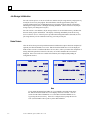
Warnings, Cautions, and Notes
as Used in This Publication
Warning
Warning notices are used in this publication to emphasize that hazardous voltages,
currents, temperatures, or other conditions that could cause personal injury exist in this
equipment or may be associated with its use.
In situations where inattention could cause either personal injury or damage to
equipment, a Warning notice is used.
Caution
Caution notices are used where equipment might be damaged if care is not taken.
Note
Notes merely call attention to information that is especially significant to understanding and
operating the equipment.
This document is based on information available at the time of its publication. While efforts
have been made to be accurate, the information contained herein does not purport to cover all
details or variations in hardware or software, nor to provide for every possible contingency in
connection with installation, operation, or maintenance.
Safety Reminders
•
DO NOT operate this machine until you have read and understood this manual—if operating for the
first time; ask your supervisor or a qualified operator for help.
•
Plug power supply into a grounded receptacle ONLY! Do not cut off the ground prong or use any cord
or adapter without a ground prong.
•
Always assume that the power is ON—do not attempt any maintenance until you have verified it is OFF.
•
Never turn the machine on while someone is performing maintenance or repair.
•
Make sure your hair and clothing are kept clear of the machine while it is in operation.
•
This product is not intended to be used in an explosive environment.
THINK SAFETY FIRST—ALWAYS PRACTICE SAFE WORK HABITS.
The 1.14 edition of this manual provided information about additional the new Ethernet communications
option—refer to Chapter 2 and Chapter 5.
The 1.15 edition provides information about additional security options and the new Calibration
Verification feature—refer to Chapter 5 and the end of Chapter 6.
The 1.16 edition provides information about the new Send Stored Jobs feature—refer to Chapter 7.
The 1.17 and 1.18 editions provides information about enhancements to the Edit Jobs function—refer to
Chapter 4 and Chapter 7. In addition, most 4Ts have a new shipping bracket—refer to Chapter 2 for
removing the shipping bracket and Appendix B for reinstalling it.
The 1.19 edition includes the CE and ETL certification listing in Chapter 1.
The 1.20 edition includes updated screen displays and corrects formatting issues.
Rev. 1.20
(This page intentionally left blank for indexing purposes.)
Table of Contents
Chapter 1
Before You Begin ............................................................................................. 1-1
General Specifications.................................................................................................. 1-1
Chapter 2
Getting Started ................................................................................................ 2-1
Section 1: Setting Up the 4T ......................................................................... 2-1
4T Shipping Bracket—Overview ................................................................................. 2-1
Determining Which Type of Shipping Brackets You Have ......................................... 2-2
Removing the Shipping Bracket................................................................................... 2-2
Positioning 4T Tracer ................................................................................................... 2-4
Positioning on 6E Edger ............................................................................................2-4
Positioning on Tabletop .............................................................................................2-4
Connecting the 4T to an Electric Outlet..................................................................... 2-5
Other Connections...................................................................................................... 2-5
Communication Connectors.......................................................................................2-5
Section 2: User Interface Overview ............................................................. 2-6
Key Pad ........................................................................................................................ 2-6
Numeric Keys ............................................................................................................2-6
ENTER ......................................................................................................................2-6
EXIT ..........................................................................................................................2-6
CLEAR ......................................................................................................................2-7
HELP .........................................................................................................................2-7
SOFT KEYS ..............................................................................................................2-7
Display ......................................................................................................................... 2-7
Types of Responses ...................................................................................................... 2-7
Numeric Entry without Decimal Place ......................................................................2-8
Numeric Entry with Decimal Place ...........................................................................2-8
List Selections............................................................................................................2-8
Toggle Selections.......................................................................................................2-8
Menu Selections.........................................................................................................2-9
Editing/Correcting Numeric Entries............................................................................. 2-9
Handling Errors ............................................................................................................ 2-9
The Accessory Kit ...................................................................................................... 2-11
Chapter 3
Powering Up .................................................................................................... 3-1
Applying Power............................................................................................................ 3-1
Display Contrast Adjustment ....................................................................................... 3-1
Job Storage Initialization.............................................................................................. 3-2
Home Screen ................................................................................................................ 3-2
Setup............................................................................................................................. 3-3
Calibration .................................................................................................................... 3-3
Menu Screen................................................................................................................. 3-3
Table of Contents
Chapter 4
Tracing Operations ......................................................................................... 4-1
Section 1: Frame Tracing ............................................................................. 4-1
Frame Mounting ........................................................................................................... 4-2
Starting Trace ............................................................................................................... 4-2
Job Number................................................................................................................4-2
Eye Selection .............................................................................................................4-3
Frame Type Selection ................................................................................................4-3
Protect Job .................................................................................................................4-3
Start Trace..................................................................................................................4-4
Stop Trace..................................................................................................................4-4
Trace Messages..........................................................................................................4-4
Editing Trace ................................................................................................................ 4-5
Edit (DBL, C, A, or B)...............................................................................................4-5
Saving or Sending a Trace............................................................................................ 4-6
Section 2: Pattern or Lens Tracing.............................................................. 4-6
Pattern Mounting.......................................................................................................... 4-6
Lens Mounting ............................................................................................................. 4-8
Starting Trace ............................................................................................................... 4-9
Job Number................................................................................................................4-9
Eye Selection .............................................................................................................4-9
Frame Type Selection ................................................................................................4-9
Protect Job .................................................................................................................4-9
Pattern/Lens Selection .............................................................................................4-10
Start Trace................................................................................................................4-10
Stop Trace................................................................................................................4-10
Editing Trace .............................................................................................................. 4-10
Edit (DBL, C, A, or B).............................................................................................4-11
Saving or Sending a Trace.......................................................................................... 4-11
Chapter 5
Setup ................................................................................................................. 5-1
Setup Menu................................................................................................................... 5-1
Checking Setup Values ................................................................................................ 5-2
Saving Setup Values..................................................................................................... 5-2
Changing Setup Values ................................................................................................ 5-3
PREFERENCES ........................................................................................................5-3
Sort Order ..................................................................................................................5-3
View Shape................................................................................................................5-3
Overwrite Warn .........................................................................................................5-4
Communications ........................................................................................................5-5
Communication Modes..............................................................................................5-5
Arcnet Options...........................................................................................................5-6
Serial Options and Protocols .....................................................................................5-6
Serial Communication to a Host................................................................................5-6
Serial Communication to Edger or Host + Edger ......................................................5-7
Baud Rate ..................................................................................................................5-7
Port Selection.............................................................................................................5-7
4T User Manual, April 8, 2009 - Rev. 1.20
Table of Contents
Password ....................................................................................................................5-8
Password Selection ....................................................................................................5-8
Protection Level.........................................................................................................5-8
Password Code (What Happens If I Forget My Password) .......................................5-9
Operator Prompts.....................................................................................................5-10
Display Contrast ......................................................................................................5-11
Frame Trace Defaults...............................................................................................5-12
Calibration Verification ...........................................................................................5-13
Verify on Power-up .................................................................................................5-13
Verify on Trace Count .............................................................................................5-14
Selecting Types of Calibration Verification ............................................................5-14
Selecting C-Size Tolerance......................................................................................5-14
Chapter 6
Calibration ........................................................................................................ 6-1
Calibration Menu ........................................................................................................... 6-1
First Time Calibration.................................................................................................... 6-2
Calibration Procedures................................................................................................... 6-2
Frame Bevel Calibration ............................................................................................6-3
Frame Size and Axis Calibration ...............................................................................6-3
Pattern Size and Pattern/Lens Axis Calibration .........................................................6-5
Beveled Lens Size Calibration...................................................................................6-5
Circumference Offset.................................................................................................6-6
Advanced Calibration ................................................................................................6-6
Calibration Verification .............................................................................................6-7
How to Use Calibration Verification .........................................................................6-8
Chapter 7
Job Storage........................................................................................................ 7-1
Job Storage Menu .......................................................................................................... 7-1
View Jobs....................................................................................................................... 7-2
Editing Jobs ................................................................................................................... 7-3
Edit (DBL, C, A, or B)...............................................................................................7-3
Send ...........................................................................................................................7-3
Protect ........................................................................................................................7-4
Delete.........................................................................................................................7-4
Find Jobs........................................................................................................................... 7-4
Delete Unprotected Jobs ................................................................................................... 7-4
Delete All Jobs.................................................................................................................. 7-5
Chapter 8
Diagnostics ........................................................................................................... 8-1
Diagnostics Screen ........................................................................................................... 8-1
Encoders ........................................................................................................................... 8-2
Communication ................................................................................................................ 8-2
Serial1 and Serial2 .....................................................................................................8-2
Arcnet ........................................................................................................................8-2
Switches............................................................................................................................ 8-3
Keypad.............................................................................................................................. 8-3
Motors............................................................................................................................... 8-3
Rev. 1.20
Table of Contents
Appendix A
Error Messages ................................................................................................ A-1
Error Overview ............................................................................................................. A-1
Error Messages ............................................................................................................. A-2
Appendix B
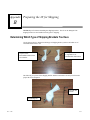
Preparing the 4T for Shipping ........................................................................B-1
Determining Which Type of Shipping Brackets You Have ..........................................B-1
Reinstalling the Shipping Bracket .................................................................................B-2
Appendix C
Preparing the 4T for Shipping--Bracket Without a Captive Screw ........... C-1
Determining Which Type of Shipping Brackets You Have ..........................................C-1
Reinstalling the Shipping Bracket .................................................................................C-2
Appendix D
Removal of the Shipping Bracket Without a Captive Screw ...................... D-1
4T Shipping Brackets—Overview................................................................................ D-1
Equipment Needed........................................................................................................ D-1
Shipping Bracket and 1/8-inch Ball Driver..................................................................D-1
Removing the Shipping Bracket ................................................................................... D-2
4T User Manual, April 8, 2009 - Rev. 1.20
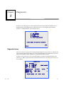
Chapter
Before You Begin
1
The 4T is fully automatic in stylus positioning, tracing of both eyes, and calibration. It combines
the extreme accuracy of the Saturn NP software with a unique user-friendly front load frameholder,
and it automatically calculates the Distance Between Lenses (DBL) and displays the shape and
DBL on an integral screen.
The 4T is manufactured as a stand-alone unit for lab use or remote site tracing, but it can also be
docked into the 6E Patternless Edger for a one-unit appearance (especially attractive for space
sensitive operations).
General Specifications
Rev. 1.20
•
Weight – 19 lbs.
•
Power Supply – Input: 115v/60hz or 220v/50hz.
Output: +5V 3A
+12V 0.5A
-12V 0.5A
•
Size – Approximately 16 inches (41 centimeters) deep/10 inches (25 centimeters) wide/
8 ½ inches (21 centimeters) high
•
Stylus - auto stylus positioning. Auto positioning in bevel of frame, positioning along edge of
pattern, positioning along bevel of lens.
•
Job Storage – 120 jobs, which can include radius data and sagitta (frame wrap) for both right &
left eye. Stored in flash memory, no batteries to replace.
•
Tracing capabilities - frames, patterns, and lenses.
•
Calibration – All calibrations performed and adjusted under program control. No mechanical
adjustments required.
•
Communications
•
• Ethernet (Model 52501 only)
• NOP Arcnet (Model 52110 only)
• OMA (Vision Council of America DCS Version 3.03)
• Gerber-Coburn emulation
• NOP Binary & ASCCII
Serial port parameters – 8 data bits, No parity, 1 stop bit, selectable baud rate: 9600-57,600
•
Bar Code Scanner – optional
•
Mounting – integral with 6E edger or tabletop operation
1-1
1
•
DBL – Automatic measurement when both eyes of a frame are traced. Single eye frame,
pattern or lens tracing permits user entry of DBL.
•
Precision - Based on encoder resolutions, radial measurements are precise to +/- 0.005mm and
axis to +/- 1/80 grad.
•
The 4T must be not used with the case removed because hazardous voltages are present.
•
The 4T should not be dropped since it was not designed for rough handling.
Conforms to UL Std 61010-1
Conforms to EN 61010-1 (Model 52500 only)
1-2
4T User Manual, April 8, 2009 - Rev. 1.20
Chapter
Getting Started
2
This chapter covers setting up and preparing the 4T Tracer for operation. In addition to setting up
the 4T for operation, an overview of the user interface will be covered in Section 2 of this chapter;
pay particular attention to this section, as this information will greatly aid in using the rest of this
manual.
Section 1: Setting Up the 4T
After removing the 4T from the shipping box, the following steps will be performed:
1.
Remove the shipping brackets.
2.
Position the 4T for operation.
3.
Connect the power supply to an electrical outlet and to the 4T.
4.
Connect additional cables.
4T Shipping Bracket—Overview
To protect the 4T from damage, there is a shipping apparatus that holds the carriage, stylus and
other critical parts in place. If you need to ship the 4T (for example, to another location within
your organization), reattach the shipping bracket—refer to the Appendices for reinstallation
instructions.
Rev. 1.20
2-1
2
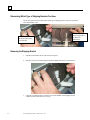
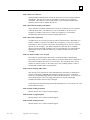
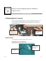
Determining Which Type of Shipping Brackets You Have
Use the two pictures below to determine which type of shipping bracket you have and which
removal directions to use.
Captive Screw:
Removal Instructions
Given Below
No Captive Screw:
Refer to Appendix C
for Removal
Instructions
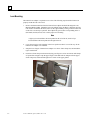
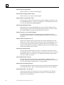
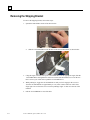
Removing the Shipping Bracket
2-2
1.
Find the 5/64-inch hex driver in the 4T Accessory Kit.
2.
Pull the nose piece forward and spread the frame holder bars apart, as shown below:
3.
Using the 5/64-inch hex driver, turn the screw in the middle of the shipping bracket
counter-clockwise until the screw is loose.
4T UserManual, April 8, 2009 - Rev. 1.20
2
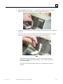
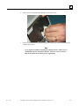
4.
Manually turn the screw while pulling gently upward until the screw slides up a couple of
inches. There is a flat side on the screw that allows it to slide up. Turn the screw until the
flat side is facing up, which allows the screw to slide out most of the way as shown below:
Flat Side
5.
After the screw is retracted, turn it ½ turn to prevent it from falling back into the bracket.
6.
Squeeze the top clip together while pulling it out as shown below:
7.
Place the shipping bracket into the 4T Accessory Kit for possible future use.
Note
NEVER ship a 4T without reinstalling the shipping bracket. Refer to
Appendix B for instructions on preparing the 4T for shipping.
Rev. 1.20
Chapter 2 Getting Started
2-3
2
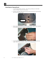
Positioning 4T Tracer
The 4T Tracer is designed so that it can be operated from a mounted position on the 6E Edger or
from a tabletop position.
Positioning on 6E Edger
Place the 4T in the flattened recess to the left of the display of the 6E. Make sure the 4T is pushed
fully to the rear of the recess. In this position the display/keypad section of the 4T should angle
down across the front of the 6E and the rear connectors of the 4T should be fully accessible.
Caution
When the 4T is mounted on the 6E, make sure the 4T is removed from the
6E before opening the cabinet of the 6E, otherwise the 4T will be dislodged
from the 6E and will be severely damaged.
Positioning on Tabletop
The 4T can be used from a tabletop position by simply setting it on the tabletop. The shape of the
4T enclosure has been designed so as to correctly angle the tracing mechanism, display, and keypad
of the 4T for comfortable operation when used from a tabletop.
2-4
4T UserManual, April 8, 2009 - Rev. 1.20
2
Connecting the 4T to an Electric Outlet
As with all electrical equipment, you must ensure proper power connection for proper functionality.
Connect the 4T to power following these steps:
1.
Before connecting power, make sure that the 4T ON/OFF switch is “OFF”.
2.
Plug the round connector from the external power supply unit into the back of the 4T. Then
plug the 115V/220V AC male plug into the wall outlet, making sure that the connections are
secure.
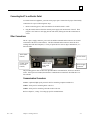
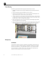
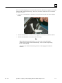
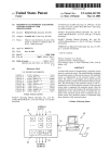
Other Connections
The 4T’s power supply connector, power switch, and data communication connectors are located
on the back of the unit (as shown below). The data communication connectors allow the 4T to
exchange data with host computers, a variety of optical devices such as edgers and blockers, or a
barcode reader.
Arcnet (BNC
Female)
COM 1 Serial
Port (9-Pin
Female)
Power Switch
COM 2 Serial
Port (9-Pin
Male)
Power Supply
Connector
The preceding picture does not show the optional Ethernet communication, which uses an RJ-45
socket. If this option is included, then the three communication connections described above are
not available.
Communication Connectors
Arcnet: (Optional) High speed protocol LAN for connecting computers and devices.
COM1: Serial port for connecting hosts or devices.
COM2: Serial port for connecting a barcode reader or devices.
Refer to Chapter 6, “Setup,” for setting up specific communications.
Rev. 1.20
Chapter 2 Getting Started
2-5
2
Section 2: User Interface Overview
This section explains the basic operations that the user will perform during interaction with the 4T
user interface. These basic operations are repeated many times through out the program and by
becoming familiar with them now, the time required to become proficient in operating the 4T will
be shortened.
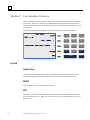
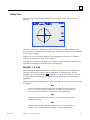
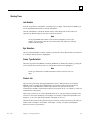
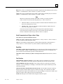
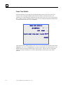
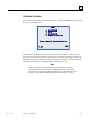
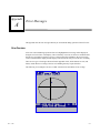
The following display/keypad diagram will be referenced during the following definitions.
TRACE FRAME
SCREEN
7
8
9
RIGHT BOTH
4
5
6
PLASTIC-WRAP METAL-WRAP PLASTIC METAL
1
2
3
CLEAR
0
HELP
JOB# 12345x
LEFT
PROTECT
MENU
ENTER
EXIT
Key Pad
Numeric Keys
The numeric keys [0] through [9] are used to enter numeric values (see Numeric Entry with &
without Decimal Place below) and to make menu selections (see Menu Selections below).
ENTER
The ENTER key is used to complete numeric entries.
EXIT
The EXIT key will exit the presently displayed screen and will cause the program to return to the
previously displayed screen. When you are on the Home Screen, press the EXIT key to go to the
Menu Screen.
2-6
4T UserManual, April 8, 2009 - Rev. 1.20
2
CLEAR
The CLEAR key is used to exit error conditions and to delete incorrectly entered data (see
Editing/Correcting Numeric Entries and Error Handling below.
HELP
The HELP key performs limited functionality in this version of the 4T program. It facilitates entry
into a series of text help screens that provide useful information regarding the screen displayed
when HELP is pressed. These screens may be menued in a manner similar to other system screens
to provide more detailed information. The method of use will be the same as described elsewhere
in this document.
SOFT KEYS
The small greenish colored keys along the right side of the display are called the Soft keys. These
keys are responsible for providing the flexibility and simplicity of the 4T user interface. The Soft
keys change function dependent upon the screen being displayed. The function or action the key
will perform will be shown on the display directly to the left of the Soft key and/or highlighted (see
below). The Soft keys will be referenced from upper most key to lower most key as Soft key 1
through Soft key 5.
In the diagram on the previous page, Soft key 1 has the SCREEN function, Soft key 2 has the
function LEFT RIGHT BOTH , Soft key 3 has the function PLASTIC METAL, Soft key 4 has
the function PROTECT, and Soft key 5 has the function MENU
The specifics of each of these Soft key functions will be described fully throughout the rest of this
manual.
Display
Information will be displayed as normal (dark blue text on a light colored background) or
highlighted (light colored text on a dark blue background). In the above diagram 12345_ , BOTH,
and METAL are highlighted, all other displayed text is normal.
A highlighted item indicates a user response is required or shows the status of a selection that can
be changed by the user. The possible types of highlighted items are, an entry field requiring user
input (see Numeric Entry below), a selection that has been made from a list (see List Selection
below), or a selection that’s been activated (see Toggle Selection below).
Normally displayed text is either simply informational text or an action that a Soft key will perform
(see Soft keys below).
Types of Responses
The following are the types of responses that the user will be required to make during program
operation.
Rev. 1.20
Chapter 2 Getting Started
2-7
2
Numeric Entry without Decimal Place
If a numeric entry is required that does not include a decimal place a highlighted entry field with
length equal to the maximum length of input will be displayed _ . The entry field will contain a
flashing cursor
Enter the desired numeric entry then press ENTER to complete the entry. After pressing ENTER,
the flashing cursor will disappear. In most cases the entered value will no longer be highlighted. In
some cases the entry will remain highlighted, this indicates that the entry can be edited by pressing
CLEAR; at which time the entry will be cleared, the flashing cursor will return and a new entry can
thus be made.
Numeric Entry with Decimal Place
If a numeric entry is required that includes a decimal place a highlighted entry field with a prepositioned decimal place and all other positions set to zero will be displayed 00.0, in this case the
entry field will not contain a flashing cursor.
Enter the desired numeric entry by entering the most significant digit followed by all proceeding
digits even if proceeding digits may be zero, then press ENTER to complete the entry. After
pressing ENTER, the entered value will no longer be highlighted. For example to enter a DBL of
14.5 enter [1], [4], [5], ENTER; to enter a DBL of 14.0 enter [1], [4], [0], ENTER.
List Selections
A List Selection is a list of items positioned next to a Soft key, with the item next to the Soft key
highlighted. In the above diagram Soft Keys 2 and 3 have List Selections. The highlighted item is
the selected item and as the Soft key next to this highlighted item is pressed, the items in the list
will shift to the right, thus moving each item in turn into the highlighted field next to the Soft key.
Toggle Selections
A Toggle Selection is an item positioned next to a Soft key that can be enabled (turned on) or
disabled (turned off) by pressing the Soft key that it is positioned next to it. When the item is
disabled it will be normally displayed and when it is enabled it will be highlighted. In the above
diagram PROTECT is a Toggle Selection and is disabled, if the Soft key next to it is pressed it will
be enabled and will display as PROTECT.
2-8
4T UserManual, April 8, 2009 - Rev. 1.20
2
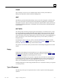
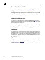
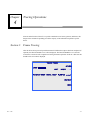
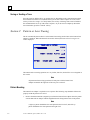
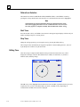
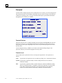
Menu Selections
A Menu Selection is a list of numbered items. The desired selection is made by pressing the
number that corresponds to the selection. The following is a display sample of a Menu Selection; to
select Diagnostics, press the [2] key.
MENU
1.
2.
3.
4.
5.
JOB STORAGE
DIAGNOSTICS
SETUP
CALIBRATION
VERIFY CALIBRATION
Press number of desired selection.
V1.31
HOME
Editing/Correcting Numeric Entries
If an incorrect value is entered during entry of a numeric value and the ENTER key has not been
pressed yet, the CLEAR key can be pressed to clear the entry and then enter the correct value.
If a displayed value needs to be altered, press the CLEAR key to clear the present entry and then
enter the correct value. The exact steps may vary depending on which screen you are in.
When the CLEAR key is pressed, if the entry field is for a numeric entry that does not include a
decimal place, a highlighted entry field with length equal to the maximum length of input will be
displayed and the highlighted entry field will contain a flashing cursor _ . If the entry field is for
a numeric entry that includes a decimal place, a highlighted entry field with a pre-positioned
decimal place and all other positions set to zero will be displayed 00.0, in this case the highlighted
entry field will not contain a flashing cursor.
Handling Errors
If an error is detected during operation of the 4T a highlighted error message will be displayed
along the lower lines of the display. The error message will indicate the cause of the error and
provide sufficient information to eliminate the error. The CLEAR key is used to exit the error
condition and is the only key accepted in response to an error. Upon pressing the CLEAR key the
error message will be cleared from the display and the display will return to the state prior to the
error occurring.
See Appendix A–Error Messages for a complete listing of all error messages.
Rev. 1.20
Chapter 2 Getting Started
2-9
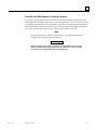
2
The following is an example of an error; a DBL value has been entered that is out of range.
# 12345
DBL=43.5
A=52.5 B=45.2 C=145.6
R
E325: entry out of range (
1
.
press CLEAR to continue
.
2-10
4T UserManual, April 8, 2009 - Rev. 1.20
to
30)
2
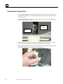
The Accessory Kit
Use the accessories provided to perform setup and other tasks such as daily cleaning. The
illustrations shown below identify the accessories that are usually shipped with the 4T.
PATTERN
CALIBRATION TEMPLATE
P/N 87249
CALIBRATION PLATE ASSY, VER.2
P/N 52317
LMB
(LENS MOUNTING BLOCK)
P/N 52280
PATTERN LENS HOLDER ASSY, VER.2
P/N 90776
w/ PATTERN RETAINER
P/N 52281
Rev. 1.20
Chapter 2 Getting Started
PATTERN AXIS
CALIBRATION TEMPLATE
P/N 87247
LENS
CALIBRATION TEMPLATE
P/N 88502
2-11
Chapter
3
Powering Up
Once all procedures outlined in Section 1: Setting Up the 4T of Chapter 2 “Getting Started” have
been accomplished the 4T is ready to be powered up.
Applying Power
Before applying power to the 4T, make sure the tracing stylus arm is fully retracted into the 4T.
Under normal operating conditions the stylus arm should be retracted, but it’s always a good
practice to verify that this is so.
The power can now be applied using the power switch located along the lower rear left hand side of
the 4T.
Display Contrast Adjustment
The display contrast is preset from the factory, but if the contrast should not be acceptable for your
lighting conditions the ARROW soft keys can be used to adjust contrast.
The contrast arrow keys will be displayed for three seconds upon power up. If neither ARROW
soft key is pressed within this time, the program will assume no contrast adjustment is required and
the program will proceed with the power up sequence. For each press of a contrast adjust key the
time out will be extended another three seconds, thus allowing for another contrast adjustment key
press if required.
Note
If the time out should occur before you get a chance to adjust the contrast, simply
turn the 4T off and back on again; then make adjustments.
Note
If the display is viewable, but additional contrast adjustment is still desired, it is probably
easier to use the contrast adjustment found in the Setup Menu; refer to Chapter 5, “Setup.”
Rev. 1.20
3-1
3
Job Storage Initialization
For code versions prior to v1.00, the 4T will now initialize the job storage memory and prepare any
stored jobs for access by the program. This initialization will take approximately thirty-five
seconds, and during this time a highlighted message will appear along the bottom of the display
indicating the storage location (1 through 120) being initialized. (Note: In Version 1.04, the job
storage capacity was changed to 120 jobs.)
For code versions v1.00 and later, the job storage structure is saved in flash memory, and therefore
does not usually require initialization. The display will change immediately from the Greeting
Screen to the Job Screen. If the 4T powers up and invalid configuration data is detected, the 4T’s
job storage memory will be scanned to locate any previously stored jobs.
Home Screen
After the 4T has been powered up and the automatic initialization sequence has been completed (if
required), the TRACE FRAME Screen or the TRACE LENS/PATTERN Screen will be displayed.
Either of these screens is considered the Home Screen, that is, where you return after completion of
tracing and menu operations. In the 4T’s idle state, one of these should be the screen that is
displayed. Note: The word Protect and the Job# field may not be displayed depending on
configurations choices.
TRACE FRAME
TRACE LENS/PATTERN
SCREEN
JOB# xxxxxXXx
LEFT
SCREEN
JOB# xxxxxXXx
LEFT
RIGHT BOTH
PLASTIC-WRAP METAL-WRAP PLASTIC METAL
RIMLESS PLASTIC METAL GROOVE
PROTECT
PROTECT
MENU
BEVELED LENS PATTERN RIMLESS LENS
Note
If you mount the Pattern/Lens holder (or if you manually spread the clamp arms),
the TRACE LENS/PATTERN Screen will display on the 4T’s monitor. You can
switch from the TRACE FRAME Screen to the TRACE LENS/PATTERN Screen
by pressing the Screen soft key. If the 4T is configured not to prompt the user for
a Job #, then START is the top soft key rather than SCREEN.
3-2
RIGHT
4T User Manual, April 8, 2009 - Rev. 1.20
3
Setup
The 4T has a factory preset setup configuration. In most instances the factory setup will be correct
for your application of the 4T, but it is advised on first power up of the 4T to review this setup to
verify correctness for your use of the 4T. See Chapter 5, “Setup” for access to setup options.
Calibration
The 4T has been factory calibrated, but it is a good practice to follow the calibration procedures on
first power up of the 4T. All calibrations are controlled and adjusted through the software;
therefore, there are no mechanical adjustments required by the user. Refer to Chapter 6,
“Calibration” for the steps in the calibration procedures.
Menu Screen
The Menu Screen provides access to all non-tracing functions of the 4T Tracer, such as:
1.
Access to Job Storage Menu for both viewing, editing, and deleting stored jobs.
2.
Access to Diagnostics Screen.
3.
Access to Setup Menu for viewing and editing the setup.
4.
Access to Calibration Menu.
5.
Access to the Calibration Verification Screen.
Note
Access the Menu Screen from the TRACE FRAME Screen (Home Screen), by
pressing the Menu soft key or the Exit key. From the Trace Lens/Pattern
Screen, press the Exit key to access the Menu Screen.
Rev. 1.20
Chapter 3 Powering Up
3-3
Chapter
Tracing Operations
4
Since the main function of the 4T is to provide a method to trace frames, patterns, and lenses; this
chapter of the manual will probably provide the majority of the information required to operate
the 4T.
Section 1: Frame Tracing
After the 4T has been powered up and the automatic initialization sequence has been completed (if
required), the TRACE FRAME Screen will be displayed. The TRACE FRAME Screen is also the
screen that is returned to after completion of tracing and menu operations. In the 4T’s idle state this
should be the screen that is displayed.
TRACE FRAME
JOB# xxxxxXXx
SCREEN
LEFT
RIGHT BOTH
PLASTIC-WRAP METAL-WRAP PLASTIC METAL
PROTECT
MENU
Rev. 1.20
4-1
4
Frame Mounting
The following steps should be followed to properly mount the frame to be traced.
1.
The frame is mounted in the frame clamps by holding the frame with temples pointed away
from 4T.
2.
Place the nasal portion of the frame behind the nose piece of the 4T.
3.
With the frame placed behind the nose piece, move the frame downward inserting the lower
edge of the frame into the v-notches on the lower frame clamp arm.
4.
Continue to push the lower frame clamp arm downward (using your fingers, rather than frame,
as a light frame may distort) until the clamps are opened far enough to insert the upper edge of
the frame into the v-notches on the upper frame clamp arm.
5.
Release downward pressure on the lower frame clamp arm, thus allowing the upper and the
lower frame clamp arms to close on the frame.
6.
Before proceeding, make sure the upper and the lower frame clamp arms have securely closed
on the frame and that the nose piece is properly centered in the nasal portion of the frame.
Starting Trace
Job Number
(This field does not appear if you have the “Permit Entry of Job Number” field on the Operator
Prompts Screen set to NO.) From the keypad enter a Job Number, consisting of up to 12 digits
followed by the ENTER key or, if the optional Barcode Scanner is used, scan the Job Number.
Once the Job Number is entered the START soft key will be displayed. No other entries are
required if the default settings for the other selections are desired.
4-2
4T User Manual, April 8, 2009 - Rev. 1.20
4
Note
The keypad and Barcode Scanner can be used inter-changeably to enter a job
number. Thus, if the barcode cannot be read or the Scanner fails, simply key in
the job number from the keypad.
Note
In some labs, the job number is assigned at the host or edger. The 4T may be
configured so that the job number field is “pre-loaded” with a job number of 1,
but is not visible.
Eye Selection
The selection of which eye(s) to trace (BOTH, RIGHT, or LEFT) is made by pressing the soft key
that has these selections next to it, until the desired selection is highlighted.
Note
In order to automatically determine a DBL for the traced frame, BOTH eyes must
be traced. Therefore, always trace BOTH eyes if possible.
Note
If the 4T is set up to use ARCNet, ASCII, or binary communications, and if you
trace BOTH eyes, the 4T will send data for the eye with the larger circumference,
oriented as the right eye.
Frame Type Selection
The Frame Type Selection (METAL, PLASTIC, METAL-WRAP, or PLASTIC-WRAP) is made
by pressing the soft key that has these selections next to it, until the desired selection is highlighted.
Note
Frame type information is used by the tracer to automatically adjust stylus
pressure, and is included in the data set that is stored or sent to an edger.
Protect Job
The Protect option protects this job from being overwritten by a future trace that uses the same job
number or when you have exceeded the maximum job storage. Refer to Chapter 4 “Stored Jobs”
and Chapter 5 “Setup”, for options controlling the desired overwrite of a protected job.
The job can be protected by pressing the PROTECT soft key. You cannot overwrite a Protected Job
without the 4T prompting you first. When protection is selected, the PROTECT soft key prompt
will be highlighted. The protection can be turned on and off with repeated presses of the
PROTECT soft key. This selection will only have an effect if a communication method is chosen
that provides for job storage at the 4T or if the 4T is connected via ARCNet to a host computer. See
Chapter 5 “Setup” for communication setup options.
Rev. 1.20
Chapter 4 Tracing Operations
4-3
4
When a job is protected a “P” will be displayed before the “#” sign proceeding a job number. This
will occur in all screens that display a traced shape. For example an unprotected job number will
display as “# 112” and a protected job number will display as “P# 112”.
Start Trace
Press the START soft key or the ENTER key to start the trace. During tracing the display will
show the job number and shape image as it is being traced.
Stop Trace
During the tracing operation, the trace can be stopped by pressing the STOP soft key.
The tracing will also automatically be stopped if a problem is detected during the trace; such as a
stylus dropout or resistance to stylus movement.
Trace Messages
During a tracing operation, you may see messages from the 4T on the screen. These messages may
or may not require you to take action of some type. The following are the messages and an
explanation for each:
E610: Stylus dropout detected: This usually occurs when the bevel position is not correctly
calibrated. The 4T will attempt to reposition the stylus in the correct location and retrace. If the 4T
cannot correct the bevel placement problem, the trace is aborted. You will need to recalibrate.
Stylus Jump—Retracing: This usually occurs if the stylus failed to position itself in the groove
but ran along the edge instead. (When such a situation occurs, the stylus may “jump” into the
groove at some point giving an inaccurate trace.) The 4T will try to position the stylus in the
groove and perform a retrace.
W630: Data bump at start of trace: This warning message comes up after unsuccessfully
attempting a retrace from a stylus jump, which may be related to the situation described above
where the stylus starts off on the edge of the frame rather than in the groove. This message is a
warning; you may still use the trace if you wish. If you receive this message repeatedly and there is
no noticeable bump or divot in the cut lens, then call Technical Support.
4-4
4T User Manual, April 8, 2009 - Rev. 1.20
4
Editing Trace
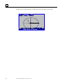
After the tracing is complete and the data has been processed, the results of the trace will be
displayed.
# 12345
DBL=13.5
A=52.5 B=52.5 C=164.9
ED=52.7
SAVE
EDIT
R
LEFT
CANCEL
The display will show Box dimensions (A and B), Circumference (C), DBL (if BOTH eyes are
traced), the Effective Diameter (ED), and shape image. Press the soft key labeled LEFT or RIGHT
to switch the eye displayed.
If BOTH eyes were not traced, the DBL entry will be highlighted and contain 00.0. The DBL is
required to be entered before the job can be completed.
If the DBL was automatically calculated or once the DBL is entered, the SAVE or SEND soft key
(depending on communication method selected) will be displayed.
Edit (DBL, C, A, or B)
To edit the displayed DBL, Circumference (C), width (A) or height (B), press the EDIT soft key
repeatedly until the field you want to change is highlighted. To change that value, press the
CLEAR key first. The field will show 00.0, which allows a new value to be entered. Type in the
new entry, then press the ENTER key to complete the entry, and the field entry will no longer be
highlighted.
During editing, the SAVE and EDIT soft keys will not be displayed. They will return once the edit
is completed.
Note
The Edit A and Edit B function is intended for small changes, no more than 10%
to 15%. Also, after you press ENTER to save the change, the 4T will perform
some computations which might round up or down your manual entry.
Note
If BOTH eyes were traced, the Circumference, A size or B size may be edited
separately on each eye.
Note
Some labs enter the DBL somewhere other than a tracer. If your lab works in
this way, refer to “Operator Prompt” in Chapter 5 to bypass the DBL entry.
Rev. 1.20
Chapter 4 Tracing Operations
4-5
4
Saving or Sending a Trace
Press the SAVE or SEND soft key to complete the job. Depending on the communication method,
the traced data will either be sent (SEND soft key) to the Lab’s Host Computer or saved (SAVE
soft key) to the 4T’s storage. (To clarify further, the soft key will change from SAVE to SEND if
the communications are set up with a Host Computer.) If you do want to completely discard the
trace information, press the CANCEL soft key.
Section 2: Pattern or Lens Tracing
The 4T automatically detects that it is in the Pattern/Lens tracing mode whenever the Pattern/Lens
Adapter is installed. When the Pattern/Lens mode is detected, the Pattern/Lens Tracing Screen
will be displayed.
TRACE LENS / PATTERN
SCREEN
JOB# _
LEFT
GROOVE
RIMLESS
RIGHT
PLASTIC METAL
PROTECT
PATTERN
RIMLESS LENS
BEVELED LENS
The Pattern and Lens tracing operations are very similar; therefore, both will be covered together in
this section.
Note
All pattern and lens tracing operations will take place with the Pattern/Lens
Adapter mounted on the right side of the nose piece on the 4T.
Pattern Mounting
The Pattern/Lens Adapter is required to trace a pattern. The following steps should be followed to
properly mount the pattern to be traced.
1.
Remove the Pattern Retainer (magnet in post) from the Pattern/Lens Adapter. Place the pattern
onto the Pattern/Lens Adapter with the alignment dowels fitting into the holes in the pattern.
Note
A right eye pattern should have the nasal pointed to the left of 4T, and a left eye
pattern should have the nasal pointed to the right of 4T.
4-6
4T User Manual, April 8, 2009 - Rev. 1.20
4
Rev. 1.20
2.
Re-attach the Pattern Retainer to hold the pattern securely to the Adapter.
3.
Lower the nose-piece until it latches in the lower position so that it is out of the way for the
Pattern/Lens Adapter to be installed.
4.
Snap the lower fingers of Pattern/Lens Adapter over lower frame clamp arm, and around the
right v-notch block.
5.
Push lower frame clamp arm downward (using your fingers to assist movement) until clamps
are opened far enough to snap the upper fingers of the Pattern/Lens Adapter onto the upper
frame clamp arm, and around the right v-notch of the upper clamp arm.
Chapter 4 Tracing Operations
4-7
4
Lens Mounting
The Pattern/Lens Adapter is required to trace a lens. The following steps should be followed to
properly mount the lens to be traced.
1.
Remove the Pattern Retainer from the Pattern/Lens Adapter and install the magnetic Lens
Mounting Block (LMB). Mount the lens to the Adapter using an adhesive blocking pad. The
lens must be mounted on the back (concave) side, approximately on the geometric center and
on the axis as accurately as possible. The Adapter has grooved lines corresponding to the A
(horizontal) and B (vertical) axis to aid in proper axis mounting.
Note
A right eye lens should have the nasal pointed to the left of the 4T, and a left eye
lens should have the nasal pointed to the right of the 4T.
4-8
2.
Lower the nose-piece until it latches in the lower position so that it is out of the way for the
Pattern/Lens Adapter to be installed.
3.
Snap the lower fingers of Pattern/Lens Adapter over lower frame clamp arm, and around the
right v-notch block.
4.
Push lower frame clamp arm downward (using your fingers to assist movement) until clamps
are opened far enough to snap the upper fingers of the Pattern/Lens Adapter onto the upper
frame clamp arm, and around the right most v-notch of the upper gimbal.
4T User Manual, April 8, 2009 - Rev. 1.20
4
Starting Trace
Job Number
From the keypad enter a Job Number, consisting of up to 12 digits, followed by the ENTER key or
use the optional Barcode Scanner to scan the Job Number.
Once the Job Number is entered the START soft key will be displayed. No other entries are
required if the default settings for the other selections are desired.
Note
The keypad and Barcode Scanner can be used inter-changeably to enter a job
number. If the barcode cannot be read or the Scanner fails, simply key in the job
number from the keypad.
Eye Selection
The Eye Selection (RIGHT or LEFT) is made by pressing the soft key that has these selections next
to it, until the desired selection is highlighted.
Frame Type Selection
The Frame Type Selection (METAL, PLASTIC, RIMLESS, or GROOVE) is made by pressing the
soft key that has these selections next to it, until the desired selection is highlighted.
Note
Frame type information is included in the data set that is stored or sent to an
edger.
Protect Job
The job can be protected by pressing the PROTECT soft key. When protection is selected the
PROTECT soft key prompt will be highlighted. The protection can be turned on and off with
repeated presses of the PROTECT soft key. This selection will only have an effect if a
communication method is chosen that provides for job storage at the 4T. See Chapter 5 “Setup” for
communication setup options.
When a job is protected a “P” will be displayed before the “#” sign proceeding a job number. This
will occur in all screens that display a traced shape. For example, an unprotected job number will
display as “# 123” and a protected job number will display as “P# 123”.
The Protect option protects this job from being overwritten by a future trace that uses the same job
number. Refer to Chapter 4 “Stored Jobs” and Chapter 5 “Setup”, for options controlling the
desired overwrite of a protected job.
Rev. 1.20
Chapter 4 Tracing Operations
4-9
4
Pattern/Lens Selection
The Pattern/Lens Selection (BEVELED LENS, RIMLESS LENS, or PATTERN) is made by
pressing the soft key that has these selections next to it, until the desired selection is highlighted.
Note
The Pattern/Lens selection determines the proper placement of the stylus
arm when engaging the Pattern or Lens. If this selection is not correct, the
trace may appear to complete normally, but the dimensions will be wrong.
Start Trace
Press the START soft key or ENTER to start the trace. During tracing the display will show the job
number and shape image as it is being traced.
Stop Trace
During the tracing operation, you can stop the trace by pressing the STOP soft key.
The tracing will also automatically be stopped if a problem is detected during the trace; such as a
stylus dropout or resistance to stylus movement.
Editing Trace
After the tracing is complete and the data has been processed the results of the trace will be
displayed. The display will show Box dimensions (A and B), Circumference (C), Effective
Diameter (ED), and shape image.
#1
A=57.2
B=57.8
DBL=00.0
C=180.4
ED=57.9
SAVE
R
EDIT
CANCEL
The DBL entry will be highlighted and contain 00.0. Enter the DBL (required before the job can be
completed). Once you have entered the DBL, the SAVE or SEND soft key (depending on
communication method selected) will be displayed.
4-10
4T User Manual, April 8, 2009 - Rev. 1.20
4
Edit (DBL, C, A, or B)
To edit the displayed DBL, Circumference (C), width (A) or height (B), press the EDIT soft key
repeatedly until the field you want to change is highlighted. To change that value, press the
CLEAR key first. The field will show 00.0, which allows a new value to be entered. Type in the
new entry, then press the ENTER key to complete the entry, and the field entry will no longer be
highlighted.
During editing, the SAVE and EDIT soft keys will not be displayed. They will return once the edit
is completed.
Note
The Edit A and Edit B function is intended for small changes, no more than 10%
to 15%. Also, after you press ENTER to save the change, the 4T will perform
some computations which might round up or down your manual entry.
Saving or Sending a Trace
Press the SAVE or SEND soft key to complete the job. Depending on the communication method
the traced data will either be sent (SEND soft key) to the Labs Host Computer or saved (SAVE soft
key) to the 4T’s storage. If the trace is to be discarded, press the CANCEL soft key.
Rev. 1.20
Chapter 4 Tracing Operations
4-11
Chapter
Setup
5
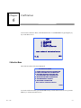
To go to the Setup Menu Screen, go to the Menu Screen first and press 3 (“SETUP”) on the 4T
keypad. (To access the Menu Screen from the TRACE FRAME Screen, press the MENU soft key
or press the EXIT key from the TRACE LENS/PATTERN Screen. Refer to the fold-out page just
before Appendix A for a graphical representation of the 4T screen flow.)
MENU
1.
2.
3.
4.
5.
JOB STORAGE
DIAGNOSTICS
SETUP
CALIBRATION
CALIBRATION VERIFICATION
Press number of desired selection.
HOME
v1.31
Note
The code version number is displayed in the lower left of the Menu Screen. The
number displayed above may not be identical to your version.
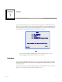
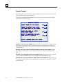
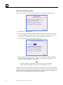
Setup Menu
After you select “3.SETUP” from the Menu Screen, you will see the Setup Menu. This menu not
only provides the ability to edit the setup values, but also provides a quick method to review the
present setup values.
If you want to exit this screen without making changes, press the HOME soft key to return to the
Home Screen or press the EXIT key to return to the Menu Screen.
Rev. 1.20
5-1
5
Note
Upon first time power up of the 4T the displayed setup values may vary from
those displayed in the following figure, as the factory defaults may have been
preset for your particular application.
Also, please note that, if your security is set to MAX on the Setup Password
Screen (see page 5-8), then you will be required to enter the password on the
Enter Password Screen before you can access this screen.
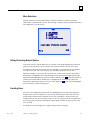
The Setup Menu Screen looks like this:
1.
2.
3.
4.
5.
6.
7.
8.
9.
SETUP MENU
PREFERENCES
SORT ORDER
: Numerical
VIEW SHAPE
: Patient
OVERWRITE WARNING
: Yes
COMMUNICATION : A-None S-Device
PASSWORD
OPERATOR PROMPTS
DISPLAY CONTRAST
FRAME TRACE DEFAULTS
PATTERN/LENS DEFAULTS
THETA AXIS SUPPORT
CALIBRATION VERIFICATION
HOME
Press number of desired selection.
Checking Setup Values
Pressing a key [1] to [9] will transfer to screens where setup items may be viewed or changed. For
convenience some of the current setup values for PREFERENCES and COMMUNICATIONS are
shown on the Setup Menu screen.
Saving Setup Values
If any setup value is changed, SAVE will be displayed next to soft key 1 on the Setup Menu screen.
If you wish to save the setup changes you made press the SAVE soft key, which will save the
changes and return you to the Menu Screen.
If changes have been made, but you do not wish to save them, press the EXIT key to return to the
Menu Screen. A prompt will inform you that the changes have not been saved. Press the CLEAR
key and then press either the HOME soft key or the EXIT key.
5-2
4T User Manual, April 8, 2009 - Rev. 1.20
5
Changing Setup Values
In order to change a setup value press the numeric key corresponding to the menu selection desired.
Upon pressing the appropriate menu selection key a setup screen specific to the chosen setup value
will be displayed. Each of these setup screens is described below.
PREFERENCES
This takes you to the Preferences screen, which has the following fields:
Sort Order
This selection allows the sort order of the stored jobs to be selected. The program allows the stored
jobs to be sorted in numerical (by job number) or chronological (oldest to newest) order. This sort
order is used when viewing stored jobs from the Job Storage Menu.
The Preferences screen displays the possible sort order selections as a list selection next to soft key
1. Make the desired selection using the soft key.
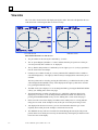
View Shape
This selection allows the orientation of the displayed shape to be selected. The program allows the
orientation to be patient or doctor view. In patient view the nasal of the right eye will be positioned
to the left and the nasal of the left eye to the right. In the doctor view the right eye nasal is to the
right and the left eye nasal to the left. The selected orientation will affect all displayed shapes, both
those in the tracing screens and those viewed from the Job Storage Menu
Note
The patient view is probably more useful, as this displays the shape in the same
orientation as the frame, pattern, or lens was positioned during tracing, allowing
the traced item to be placed against the display for shape or size verification.
The Preferences screen displays the possible orientation selections as a list selection next to Soft
Key 2. Make the desired selection using the soft key.
Rev. 1.20
Chapter 5 Setup
5-3
5
Overwrite Warn
This selection allows the overwrite warning for already existing job numbers in job storage to be
enabled or disabled. If the Overwrite Warning is enabled (YES selected), then the program
will display a warning message if a job number is entered that already exists in the job
storage. The user must then decide whether to overwrite the existing job or to choose a new
job number. If the overwrite warning is disabled (NO selected), then the program will
automatically overwrite any existing job numbers, without any message to or responses required
from the user.
When the 4T job storage becomes full and you enter a new job number, the 4T will overwrite the
oldest unprotected job in storage. This will be done either with or without a warning—depending
on the Overwrite Warn setting (warning given if this field is enabled). If you elect not to overwrite
the oldest job when prompted, you must manually deleted one of more jobs before any new jobs
can be stored in the 4T.
To enable or disable this option, press Soft Key 3 on the Preferences Screen (YES enables, NO
disables).
5-4
4T User Manual, April 8, 2009 - Rev. 1.20
5
Communications
This selection allows the setup values associated with the communication options to be selected.
Upon selecting the COMMUNICATION menu selection, the Communication Setup Screen will be
displayed. This screen will display all the possible communication selections, some as list
selections and others as numeric entry fields. Make the desired selections, then press the ENTER
key and the program will return to the Setup Menu screen.
Communication Modes
Arcnet: Provides a fast data line to an edger or to a host computer. It is especially useful when a
large number of devices need to be interconnected. Computers must be equipped with an Arcnet
interface module, or must use an Arcnet Gateway device. Arcnet requires specialized hardware
that may not be installed in the 4T.
Serial: Provides a data line that is slower than Arcnet, but may be less expensive. It also has the
advantage of permitting communications using an industry standard protocol (OMA), which
permits communications to various types of devices.
Ethernet: The Ethernet option does not appear explicitly on the COMMUNCATIONS SETUP
screen. Provides a data link to a host computer. This option requires additional software at the host
computer. 4Ts equipped with Ethernet hardware do not have the ability to communicate using
other modes of operation.
If you are using the Ethernet communications option, you will need to specify the following on the
Communications Screen:
Arcnet:
Serial To:
Protocol:
COM1 KBAUD:
Rev. 1.20
Chapter 5 Setup
NONE
Host
OMA (or OMA + Z)
19.2
5-5
5
Arcnet Options
Your choices are HOST, EDGER, or NONE. If you choose HOST or EDGER, you can still
communicate serially to a Host, but none of the other serial options described below are available.
Note that on some 4Ts, the Arcnet feature is not available.
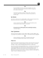
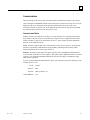
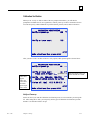
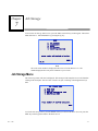
Serial Options and Protocols
The COMMUNICATION screen changes depending on which serial connection and protocol
options you select. The pictures shown below include settings you might use in your operation:
COMMUNICATIONS
COMMUNICATIONS
ARCNET TO:
LAN ID 255
NONE
HOST
SERIAL TO:
ARCNET TO:
LAN ID 255
EDGER
NONE
HOST
SERIAL TO:
PC
EDGER
NONE
NONE PC+DEVICE DEVICE PC
PROTOCOL:
G-C BIN ASC OMA+Z OMA
(Send Z-data with trace.)
PROTOCOL:
G-C BIN ASC OMA+Z OMA
(Send Z-data with trace.)
COM1 KBAUD:
COM1 KBAUD:
57.6 38.4 28.8 19.2 9.6
57.6 38.4 28.8 19.2 9.6
Make selections – press ENTER
Make selections – press ENTER
Both Host and Edger Selected
Host Selected
COMMUNICATIONS
ARCNET TO:
LAN ID 255
SERIAL TO:
HOST
EDGER
PC NONE PC+DEVICE
NONE
DEVICE
PROTOCOL:
G-C BIN ASC OMA+Z OMA
(Send Z-data with trace.)
COM1 KBAUD:
57.6 38.4 28.8 19.2 9.6
Make selections – press ENTER
Edger Selected
Serial Communication to a Host
One of these protocols should be selected:
OMA: This industry standard permits communication to a variety of computers or devices.
OMA + Z: This industry standard supports 3-D data (Z data) and permits communication to a
variety of computers or devices.
G-C (Gerber-Coburn): This is the Gerber-Coburn proprietary protocol, but it is supported by some
third party host software products. (Time to transfer 1 eye data: 1 to 2 seconds) It does not support
3-D data.
5-6
4T User Manual, April 8, 2009 - Rev. 1.20
5
BIN (binary): This is a communication protocol that is supported by some third party host software
products—see NOTE below. (Time to transfer 1 eye data: 0.5 second)
ASCII: This is also a communication protocol that is supported by some third party host software
products—see NOTE below. (Time to transfer 1 eye data: 1 second)
Note
When the serial protocol selected is either BIN or ASCII, you will be presented
with two choices for the Trace Data Tag (Soft key 4). The two choices are:
•
TRACE SOURCE—This causes the data to include an indicator whether the traced
object was a pattern/lens or a frame.
•
FRAME TYPE—This causes the data to include an indicator whether the traced
frame was metal, plastic, or rimless.
Your choice for the Trace Data Tag will often depend on requirements imposed
by the host software product you are using. Check with the provider of the host
software to determine which (if any) of the two choices is required.
Serial Communication to Edger or Host + Edger
One of these two protocols should be selected:
OMA: This industry standard permits communication to a variety of devices. (Time to transfer 1
eye data: around 4 seconds at baud rate=9600)
OMA + Z: This industry standard supports 3-D data (Z data) and permits communication to a
variety of devices. (Time to transfer 1 eye data: around 4 seconds at baud rate=9600)
Baud Rate
With OMA or OMA+Z protocol selected: You can select the speed of data transfer using the soft
key corresponding to COM1 or COM2, depending on which serial port you are modifying. The
speed set at the 4T must match the speed set at the attached device.
With either Gerber-Coburn (G-C), BIN or ASCII protocol selected: The baud rate is fixed at
9600.
Port Selection
With the HOST connection selected: Use the COM1 serial port to attach the 4T to the host
computer. A null modem is not usually required. COM2 may be used with a barcode reader.
With the EDGER connection selected: Use the COM1 serial port to attach the 4T to the host
computer. If you are attaching to a 6E Edger, a null modem is not required. COM2 may be used
with a barcode reader.
With both the HOST and EDGER connection selected: Use the COM1 serial port to attach to
the host computer and the COM2 serial port to attach to the edger. The connection on COM1
generally does not require a null modem; however, when a 6E Edger is connected to COM2, a null
modem is required. Other edgers may also need a null modem.
NOTE: Barcode input is not available when using this connection option.
Rev. 1.20
Chapter 5 Setup
5-7
5
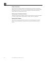
Password
Use this screen to change the password or to change the level of security you want for using the 4T.
The chosen password is used in editing or deleting stored jobs, and in accessing certain functions
within the 4T operating system. The types of functions that require a password are determined
through the level of security you establish.
PASSWORD SETUP
ENTER CURRENT PASSWORD
ENTER NEW PASSWORD
RE-ENTER NEW PASSWORD
Protection Level:
NONE
MAX NORMAL
CANCEL
password code:xxxxxx
Password Selection
The password can be one to six digits in length. Upon selecting the PASSWORD menu selection,
the Password Setup Screen will be displayed. Follow the instructions provided on the screen to
change the password. Upon completing re-entry of the new password, the program will return to
the Setup Menu.
Use the CANCEL soft key or EXIT key to exit this screen without making changes to the
password. Either key will return the program to the Setup Menu.
Protection Level
Use the fourth soft key (Protection Level) to set the password protection. The options are as
follows:
None:
A password is not required to access or modify any field, job, etc. within the 4T software.
Normal: A password is required to modify or delete stored jobs and to access Advanced
Calibration settings.
Max:
5-8
A password is required to modify or delete stored jobs, Advanced Calibration settings,
and size of calibration objects. In addition, a password is required to access the Setup
screen and its functions, the Diagnostics screen and its functions, the Calibration
Offsets screen and its functions, and to skip Calibration Verification options.
4T User Manual, April 8, 2009 - Rev. 1.20
5
Password Code (What Happens If I Forget My Password)
If you forget the current password, call Technical Service and provide them with the “Password
Code” displayed at the bottom of the screen (see screen sample above) to receive a special one-time
use password. The Technical Service representative will provide you with a special password that
can be used in place of the current password. This “Password Code” will also appear on the Enter
Password Screen that appears when you try to access a password protected screen.
Note
This special password is valid for use one time only. A new special password will
be required each time the password is forgotten.
Warning
The special password is based on the password code and the password code
changes each time the Password Setup Screen is displayed, so do not exit this
screen before receiving and using the special password.
Rev. 1.20
Chapter 5 Setup
5-9
5
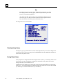
Operator Prompts
This selection allows you to control how much automation you want at certain parts of the process
of tracing a frame and saving the information.
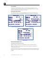
When you select OPERATOR PROMPTS from the Setup Menu, you will see a screen with the
same fields as the one shown below:
OPERATOR PROMPTS
PERMIT ENTRY OF JOB NUMBER
NO YES
PROMPT TO START TRACE AFTER
BAR CODE ENTRY OF JOB NUMBER
NO YES
PROMPT TO ENTER DBL AFTER
SINGLE-SIDE TRACE
NO YES
PROMPT TO SAVE/SEND JOB DATA
WHEN TRACE IS COMPLETE
NO YES
Select options then press ENTER
PERMIT ENTRY OF JOB NUMBER: Change this to NO if you want the 4T to assign a default
job number 1 to each job, for example, if actual job numbers are assigned at a host computer or
edger in your lab environment. Also, if this is set to NO, the 4T will not display the Job# prompt
on the Trace Screen.
PROMPT TO START TRACE AFTER BAR CODE ENTRY OF JOB NUMBER: Change
this to NO if you want the trace to start automatically after you perform a bar code job number
entry.
PROMPT TO ENTER DBL AFTER SINGLE-SIDE TRACE: Change this to NO if you do not
want to be prompted for DBL (distance between lenses) after doing a single-side trace.
PROMPT TO SAVE/SEND JOB DATA WHEN TRACE IS COMPLETE: Change this to NO
if you want to skip the prompt and either automatically save the job data or automatically send the
job data to a host.
5-10
4T User Manual, April 8, 2009 - Rev. 1.20
5
Display Contrast
This selection allows the display contrast to be adjusted. The adjustment resolution provided is
identical to that offered at power-up.
When you select DISPLAY CONTRAST from the Setup Menu, the Display Contrast Setup Screen
will be displayed. Follow the instructions provided on the screen. Upon pressing the APPLY soft
key, the program will return to the Setup Menu. Unlike the other setup values, any changes made to
the contrast are automatically saved and it is not required to press the SAVE soft key in the Setup
Menu.
DISPLAY CONTRAST ADJUSTMENT
APPLY
Use arrow keys to
adjust display contrast.
S
T
Press APPLY when contrast set
Rev. 1.20
Chapter 5 Setup
5-11
5
Frame Trace Defaults
This selection shows a screen that allows the default settings for the Frame Trace Screen to be
selected. Upon selecting the FRAME TRACE DEFAULTS menu selection, the Frame Trace
Defaults Screen will be displayed, which looks the same as the Frame Trace Screen except for Soft
Key 1. When you make a selection on this screen, it becomes a default setting that is automatically
set whenever the Frame Trace Screen is displayed.
FRAME TRACE DEFAULTS
USE DEFAULTS
LEFT
USE PREVIOUS
RIGHT BOTH
PLASTIC-WRAP METAL-WRAP PLASTIC METAL
PROTECT
These defaults will be displayed on the Frame Trace Screen if you have the USE DEFAULTS field
highlighted. If it is set to “USE PREVIOUS” (as shown in the sample screen presented above), the
defaults will be selected upon initial bootup or at the first trace. After the first trace, the settings
will be set to those used on the previous trace, and the defaults selected on this screen will be
ignored.
5-12
4T User Manual, April 8, 2009 - Rev. 1.20
5
Calibration Verification
When you set “Verify” to YES on either of the two prompts shown below, you will then be
prompted to recalibrate the 4T on a regular basis, either at power-up or after a set number of traces.
You can also specify which calibrations to perform (frames, patterns, lenses) and set tolerances.
CALIBRATION VERIFICATION
Verify on power-up
YES NO
Verify on trace count
YES NO
APPLY
Make selections then press APPLY
After you select “YES” on either of the two verify options, other options appear as shown below:
CALIBRATION VERIFICATION
Verify on power-up
NO YES
Verify on trace count
Trace count trigger: 200
These lines
appear
when you
select YES
for either
power-up or
trace count.
NO YES
This line appears when you
select YES for trace count.
Verify
ALL FRM+LENS FRM+PTRN FRM
(Select which objects to verify)
{
C-size tol. (mm)
0.15 0.30 0.25 0.20
APPLY
Make selections then press APPLY
Verify on Power-up
Set this to YES if you want the Calibration Verification process to occur each time you start up the
4T. After setting this to YES, you can specify which types of Calibration Verification to perform
and the C-size tolerance limits to accept.
Rev. 1.20
Chapter 5 Setup
5-13
5
Verify on Trace Count
Set this to YES if you want the Calibration Verification process to occur after a user-specified
number of traces. After setting this to YES, you can specify the number of traces needed to trigger
the Calibration Verification. You can also specify which types of Calibration Verification to
perform and the C-size tolerance limits to accept.
Selecting Types of Calibration Verification
Calibration Verification always includes verification of frame calibration. The selections available
to you allow for frame and lens, frame and pattern, or all three (frame, lens, and pattern).
Selecting C-Size Tolerance
This allows you to specify the allowable circumference error measured during the verification
process. If the measured difference is greater than what is specified, a calibration sequence is
initiated.
5-14
4T User Manual, April 8, 2009 - Rev. 1.20
Chapter
Calibration
6
To access the Calibration Menu, select Menu Selection “4. CALIBRATION” by pressing the [4]
key on the Menu Screen.
MENU
1.
2.
3.
4.
5.
JOB STORAGE
DIAGNOSTICS
SETUP
CALIBRATION
VERIFY CALIBRATION
Press number of desired selection.
HOME
V1.31
Calibration Menu
The Calibration Menu will now be displayed.
CALIBRATION MENU
1. FRAME BEVEL POSITION CALIBRATION
2. FRAME SIZE AND AXIS CALIBRATION
3. PATTERN/RIMLESS LENS SIZE AND
PATTERN/LENS AXIS CALIBRATION
4. BEVELED LENS SIZE CALIBRATION
5. CIRCUMFERENCE OFFSETS
6. ADVANCED CALIBRATION
Press number of desired selection.
HOME
To exit the Calibration Menu, press the HOME soft key to return to the Home Screen or press the
EXIT key to return to the Menu Screen.
Rev. 1.20
6-1
6
Note
All calibrations and adjustments required by the 4T Tracer are performed
via program control. Under normal circumstances, there is no need for any
mechanical adjustments.
First Time Calibration
Even though the 4T has been factory calibrated, it is advisable to perform a complete calibration
before using the 4T for the first time, as there is no way of controlling the unpredictable effects of
shipping.
To calibrate the 4T, perform the following steps in this order:
1.
Select menu selection “1. FRAME BEVEL POSITION CALIBRATION” and perform this
calibration.
2.
Select menu selection “2. FRAME SIZE AND AXIS CALIBRATION” and perform this
calibration.
3.
Select menu selection “3. PATTERN SIZE AND PATTERN/LENS AXIS CALIBRATION”
and perform this calibration.
4.
Select menu selection “4. BEVELED LENS SIZE CALIBRATION” and perform this
calibration.
5.
Select menu selection “5. CIRCUMFERENCE OFFSETS” and perform this calibration, if
needed
Calibration Procedures
The calibration procedures can be performed individually following these rules:
•
The “Frame Bevel Calibration” can be performed individually without any effects on the other
calibrations.
•
The “Pattern Size and Pattern/Lens Axis Calibration” or “Beveled Lens Size Calibration” can
be performed individually without any effects on the other calibrations.
Caution
The “Pattern Size and Pattern/Lens Axis Calibration” or “Beveled Lens Size
Calibration” should be performed individually only if the frame sizing is
correct. Otherwise, perform the “Frame Size and Axis Calibration” before
performing the “Pattern Size and Pattern/Lens Axis Calibration” or
“Beveled Lens Size Calibration.”
•
6-2
The “Frame Size and Axis Calibration” should never be performed individually. Anytime this
calibration is performed the “Pattern Size and Pattern/Lens Axis Calibration” and “Beveled
4T User Manual, April 8, 2009 - Rev. 1.20
6
Lens Size Calibration” must also be performed afterwards. Changes caused by the Frame
Calibration will also affect the pattern and lens sizing.
If you desire to perform them all they should be done in menu order, see “First Time Calibration”
above for instructions on performing a complete calibration.
Frame Bevel Calibration
This selection provides for the calibration procedure for placing the tracing stylus into position in
the frame bevel. The instructions displayed on the screen will step you through the calibration
procedure. The following is an overview of the steps.
1.
Place a light-weight to medium-weight metal frame with average curvature and approximately
38 mm “B” size in the frame holder.
2.
From the Calibration Screen, press “[1] FRAME BEVEL POSITION CALIBRATION.”
3.
Pull the stylus tip out and position the tip into the frame bevel (right eye).
4.
While holding the stylus securely in this position, so as to get a stable reading, press the
APPLY soft key.
5.
Release the stylus so that it retracts. The carriage mechanism will move to the left side of the
frame.
6.
As in Steps 3 through 5, pull out the stylus tip and position it securely, this time in the left eye
frame bevel.
7.
Press the Apply soft key; then release the stylus arm.
8.
The calibration is complete and the program will return to the Calibration Menu.
9.
Remove the frame.
Frame Size and Axis Calibration
This selection provides for the automatic calibration of the frame size and for either automatic or
manual calibration of the frame axis. This calibration procedure requires use of the frame
calibration plate. The frame calibration plate is a frame style template that contains a circular hole
with a diameter of approximately 55 mm in the right eye position. The left eye position is a partial
circular hole with a diameter of approximately 71 mm with a flattened bottom portion.
There are two available methods for calibrating the frame axis: AUTO and MANUAL. In AUTO
mode, the 4T computes calibration values and stores them in its memory. In manual mode, the axis
calibration values will not be stored, but can be keyed in manually using the “Advanced
Calibration” screen. The 4T is shipped with the axis calibration method set to MANUAL.
Rev. 1.20
Chapter 6 Calibration
6-3
6
The instructions displayed on the screen will step you through the calibration procedure. The
following is an overview of the steps:
1.
Mount the frame calibration plate as you would a frame, with the smaller circle positioned in
the right eye position.
Make sure that the alignment mark is aligned with the front vinyl-covered pin on the right
frame holder insert. Assure that the plate is seated completely down into the “V” created by the
vinyl-covered pins.
6-4
2.
Enter the “Cal Values” as printed on the plate. After you have done this once, the 4T will
remember these values. Note, if your plate does not have a dual set of numbers labeled at each
eye position or does not specifically state “Cal Value,” the single numbers labeled on the plate
should be considered the Cal Values.
3.
Enter the axis calibration method you want (AUTO or MANUAL)—unless you suspect the
axis is not calibrated correctly, leave this field at the factory default (MANUAL). The
MANUAL selection will bypass the axis calibration, leaving the axis values the same.
4.
Press the START soft key to begin calibration tracing.
5.
The right eye will be traced, and the “PROCESSING DATA” message will be displayed. The
left eye will not be traced until the right eye data has been processed.
6.
The left eye will now be traced and the “PROCESSING DATA” message will again be
displayed.
7.
Steps 4 and 5 may be repeated, depending on the version of your software.
8.
The “CALIBRATION COMPLETE” message will be displayed and the program will return to
the Calibration Menu.
9.
Remove the calibration plate.
4T User Manual, April 8, 2009 - Rev. 1.20
6
Pattern Size and Pattern/Lens Axis Calibration
This section provides for the axis calibration of the pattern and lens and size calibration for patterns
and rimless. This calibration procedure requires the use of the pattern axis calibration template (P/N
87247)—refer to page 2-12 for a picture.
The following is an overview of the steps:
1.
Go to the Calibration screen.
2.
From the Calibration menu, select “3. PATTERN SIZE AND PATTERN/LENS AXIS
CALIBRATION.”
3.
Respond to the prompts:
A. Mount the pattern axis calibration template in the right eye position using the Pattern/Lens
Adapter. Mount the point of the pattern axis calibration template facing toward the right
of the machine.
B. Enter the template diameter as marked on the template. If no diameter is marked, enter
58.0.
4.
Enter the axis calibration method you want (AUTO or MANUAL)—unless you suspect the
axis is not calibrated correctly, leave this field at the factory default (MANUAL). The
MANUAL selection will bypass the axis calibration, leaving the axis values the same.
5.
Press the START soft key to begin calibration tracing.
6.
The pattern will be traced and the “PROCESSING DATA” message will be displayed.
7.
The “CALIBRATION COMPLETE” message will be displayed and the program will return to
the Calibration Menu.
8.
Remove the calibration template.
Beveled Lens Size Calibration
This section provides for the automatic calibration of the beveled lens size. This calibration
procedure requires the use of the Lens calibration template. The Lens calibration template is a
circular beveled lens with a diameter of 50-58 mm.
The instructions displayed on the screen will step you through the calibration procedure. The
following is an overview of the steps:
Rev. 1.20
1.
Mount the Lens calibration template in the right eye tracing position, using the LMB and
Lens/Pattern Adapter.
2.
Enter the correct diameter 58.0. After this is done the first time, the 4T will remember this
value.
3.
Press the START soft key to begin calibration tracing.
3.
The Lens will be traced and the “PROCESSING DATA” message will be displayed.
Chapter 6 Calibration
6-5
6
4.
The “CALIBRATION COMPLETE” message will be displayed and the program will return to
the Calibration Menu.
5.
Remove the Lens calibration template.
Circumference Offset
Use this calibration if you find that the circumference is consistently off by a specific amount. You
can add separate offsets for frames, patterns, and lenses. The need for these offsets more often
occurs in remote site tracing operations.
The instructions displayed on the screen will step you through the Circumference Offset procedure.
The following is an overview of the steps:
1.
Go to the Calibration Screen.
2.
There are three fields on this screen: Frame, Pattern/Rimless Lens, and Beveled Lens. Type
the offset needed (in mm) into the appropriate field. Your limits are +/— 5 mm.
Advanced Calibration
This selection provides access to the automatically produced calibration values. Access to this
menu selection is only required under unusual circumstances and is thus designed for use by
Technical Service personnel, or for use under the supervision of these personnel.
6-6
4T User Manual, April 8, 2009 - Rev. 1.20
6
Calibration Verification
To access the Calibration Menu, select Menu Selection “5. VERIFY CALIBRATION” by pressing
the [5] key on the Menu Screen.
MENU
1.
2.
3.
4.
5.
JOB STORAGE
DIAGNOSTICS
SETUP
CALIBRATION
VERIFY CALIBRATION
Press number of desired selection.
HOME
V1.31
The Calibration Verification process checks the calibration of the 4T, that is, whether or not the
traces meet the user-specified tolerances. You can set up Calibration Verification to initiate each
time you power up the 4T or after a set number of traces—refer to the end of Chapter 5 “Setup” for
instructions on setting up Calibration Verification to initiate automatically. You can also begin the
Calibration Verification process manually (option 5 from the Menu Screen).
Note
Unlike the other aspects of Calibration discussed in this chapter, you do not
access Calibration Verification from the CALIBRATION Screen. Instead, you
will either press 5 on the 4T keypad from the Menu Screen discussed at the top of
this page, or it will start up automatically as discussed in Chapter 3, “Setup.”
Rev. 1.20
Chapter 6 Calibration
6-7
6
How to Use Calibration Verification
After entering Calibration Verification as discussed above, you will see the following screen:
1.
Mount the Frame Calibration Plate.
2.
Press the top soft key (START) to begin the Frame verification. If the calibration is verified,
then you will either go to the Menu Screen or go to the next type of verification set for your
4T—refer to the end of Chapter 5 “Setup” for types of calibration you can select.
If the verification fails, you will see the following screen:
3.
Upon seeing the Calibration Verification Failure Screen, press the top soft key (START) to
perform an automated calibration. Once it finishes, you will either go to the Menu Screen or
go to the next type of verification set for your 4T.
Note
To skip the calibration at this point, press the Cancel soft key—canceling may
require a password, depending on the security level established for your 4T.
Calibration Verification always includes verification of frame calibration. The selections available
within Setup allow for frame and lens, frame and pattern, or all three (frame, lens, and pattern). The
steps and screens in verifying calibration for pattern/rimless lenses or beveled or beveled lenses are
similar to those used in verifying frame calibration as described above.
6-8
4T User Manual, April 8, 2009 - Rev. 1.20
Chapter
Job Storage
7
To access the Job Storage Menu Screen, press the Menu or the Exit key on the keypad. Then select
Menu Selection “1. JOB STORAGE” by pressing the [1] key.
MENU
1.
2.
3.
4.
5.
JOB STORAGE
DIAGNOSTICS
SETUP
CALIBRATION
VERIFY CALIBRATION
Press number of desired selection.
HOME
V1.31
Note
The code version number is displayed in the lower left of the Menu Screen. The
number displayed above may not be identical to your version.
Job Storage Menu
The Job Storage Menu will now be displayed. This menu provides complete access to all functions
relating to the stored jobs. The 4T Tracer can store 120 jobs, consisting of both right and left eye
data.
JOB STORAGE MENU
1.
2.
3.
4.
VIEW JOBS
FIND JOB
DELETE UNPROTECTED JOBS
DELETE ALL JOBS
Press number of desired selection.
HOME
To exit the Job Storage Menu, press the HOME soft key to return to the Home Screen or press the
EXIT key on the keypad to return to the Menu Screen.
Rev. 1.20
7-1
7
View Jobs
The “View Jobs” menu selection will display stored job in order. The order will depend on the sort
order (numerical or chronological) that was chosen in setup.
P#12345
A=52.50
DBL=13.50
B=45.20 C=145.60
ED=52.70
P#12345
A=52.50
DBL=13.50
B=45.20 C=145.60
SEND
EDIT
R
R
LEFT
EDIT/DEL/SEND
PROTECT
HOME
DELETE
1/55
SOURCE=METAL FRAME
View Jobs Screen
Edit Jobs Screen
Information about the View Jobs Screen:
•
The job number for this stored job is indicated by “# 12345”.
•
The “P” proceeding the job number “# 12345” indicates that this job is protected. If this job
were not protected, there would be no “P” displayed.
•
The eye that this data pertains to is indicated by an “R” (right eye) or “L” (left eye) positioned
near the center of the traced shape.
•
If both eyes are available for this job, a soft key labeled LEFT or RIGHT will be available to
switch the displayed eye. The right eye data will always be displayed first when both eyes are
available.
The left eye data can be viewed by pressing the LEFT soft key, at which time the left eye data
will be displayed and a RIGHT soft key will be displayed. The right eye data can be returned
to by pressing the RIGHT soft key.
7-2
•
The DBL for the job is displayed. You can change the DBL by pressing the EDIT/DEL/SEND
soft key (see “Editing Jobs” on the next page).
•
The Box dimensions (A and B), Circumference (C), and Effective Diameter (ED) for the
displayed eye are shown. You can change the Box dimensions and the Circumference by
pressing the EDIT/DEL/SEND soft key (see the “Editing Jobs” section on the next page).
•
In the lower left corner of the display, an indicator shows which job we’re viewing and how
many jobs are stored. In the example screen, the first job of 55 total jobs is being viewed.
•
Also displayed in the lower left corner, you can view information about the type of trace
originally done on this job (in the example, a metal frame was traced).
•
The ARROW soft keys will move forward or backward through the stored jobs. The present
position in the list of stored jobs can always be determined by checking the job indicator in the
lower left corner of the display.
4T User Manual, April 8, 2009 - Rev. 1.20
7
•
If you want to delete the viewed job, press the EDIT/DEL/SEND soft key (see the “Editing
Jobs” section below).
•
To send a stored job to an attached Host Computer, press the EDIT/DEL/SEND soft key (see
the “Sending Stored Jobs” section below).
Editing Jobs
When you press the EDIT/DEL/SEND soft key from the View Jobs Screen, you will enter the
Stored Jobs Edit Screen—see sample screen on opposing page. This screen may require a
password.
If you change information on this screen, the SAVE soft key will be displayed. To save the
changes, press the SAVE soft key. If you do not wish to save the changes or no changes have been
made, exit the Stored Jobs Edit Screen by pressing the EXIT key. Upon exit the program will
return to the View Jobs Screen. (Refer to the “Edit” section on the next page for specific
instructions on editing jobs.)
Edit (DBL, C, A, or B)
To edit the displayed DBL, Circumference (C), width (A) or height (B), press the EDIT soft key
repeatedly until the field you want to change is highlighted. To change that value, press the
CLEAR key first. The field will show 00.0, which allows a new value to be entered. Type in the
new entry, then press the ENTER key to complete the entry, and the field entry will no longer be
highlighted.
During editing, the SAVE and EDIT soft keys will not be displayed. They will return once the edit
is completed.
Note
The Edit A and Edit B function is intended for small changes, no more than 10%
to 15%. Also, after you press ENTER to save the change, the 4T will perform
some computations which might round up or down your manual entry.
Send
If the 4T is configured so that its serial connection is either “PC” or “DEVICE + PC,” when you
enter the Stored Jobs Edit Screen, you can send the displayed job to the Host Computer by pressing
the SEND soft key. If you edited any of the information on the screen (such as changing the
circumference or DBL), the SEND soft key will change to “SAVE.” In that situation, you must
press the SAVE soft key and then re-enter the Stored Jobs Edit Screen (by pressing the
EDIT/DEL/SEND soft key to SEND the job to the Host Computer.
Rev. 1.20
Chapter 7 Job Storage
7-3
7
Protect
If the viewed job is protected a “P” will be displayed before the “#” sign proceeding the job
number and the PROTECT soft key prompt will be highlighted. The job can be protected or unprotected by pressing the PROTECT soft key.
The Protect option protects this job from being overwritten by a future trace that uses the same job
number (even if the Overwrite Warn feature is disabled).
Delete
Press the DELETE soft key to delete the viewed job. A verification screen will be displayed that
requires the user to verify this is the action they desire.
If the job is protected an error message will be displayed. The job can not be deleted while it is
protected. If it is desired to delete a protected job, un-protect the job using the PROTECT soft key
(see above).
Caution
There is NO UNDELETE FEATURE. Once the jobs are deleted, they are
gone.
Find Jobs
To go directly to a specific job or to check if a specific job exists, select menu selection “2. Find
Job” selection from the Job Storage Menu.
The desired job number will be requested, enter the desired job number and follow the instructions
on the screen. If the desired job is found, the “View Jobs” screen shown above will be displayed,
showing the data for the selected job. If the job is not found, an error message will be displayed
indicating that the job was not found.
Delete Unprotected Jobs
The “Delete Unprotected Jobs” selection as the name implies will delete all unprotected jobs.
This menu selection may be password protected. Once the password is correctly entered, a screen
indicating how many jobs will be deleted is displayed and a verification to proceed with this action
is required.
Caution
There is NO UNDELETE FEATURE. Once the jobs are deleted, they are
gone from the system permanently.
7-4
4T User Manual, April 8, 2009 - Rev. 1.20
7
Delete All Jobs
The “Delete All Jobs” selection will delete all protected and unprotected jobs.
This menu selection may be password protected. If you are prompted for a password, enter the
password, and you will then see a screen indicating how many jobs will be deleted. You will be
required to verify this action to proceed.
Caution
There is NO UNDELETE FEATURE. Once the jobs are deleted, they are
gone from the system permanently.
Rev. 1.20
Chapter 7 Job Storage
7-5
Chapter
Diagnostics
8
In order to access the Diagnostics Menu make sure the Home Screen (TRACE FRAME Screen) is
displayed, then press the Menu soft key and the Menu Screen will be displayed. Select Menu
Selection “2. DIAGNOSTICS” by pressing the [2] key.
MENU
1.
2.
3.
4.
5.
JOB STORAGE
DIAGNOSTICS
SETUP
CALIBRATION
VERIFY CALIBRATION
Press number of desired selection.
HOME
V1.31
Diagnostics Screen
There are no menu selection items associated with the Diagnostics menu, as there are with the other
menu selections made from the Menu Screen. All required diagnostics are contained on one screen.
This screen should provide the capability to test all functions of the 4T Tracer.
In order to exit the Diagnostics Screen press the EXIT key, which will return the program to the
Menu Screen. Note: A password will be required if the Protection Level (on the Password Screen)
is set to MAX.
0
DIAGNOSTICS
AXIS
SIZE
BEVEL
R/L
ENCODERS
0
0.00
0
0.00
0
0.00
0
0.00
COMMUNICATION
SERIAL1: AA
SERIAL2: AA
ARCNET: YES
RESET COUNTS
SWITCHES
RIGHT FRAME
LEFT LENS
SELECT MOTOR:
Rev. 1.20
grad
deg
mm
mm
R/L
BEVEL
KEYPAD
S
T
SIZE
AXIS
8-1
8
Encoders
Encoders are electromagnetic devices inside the 4T that provide a numerical read-out of the
positions of the removable axes of the trace mechanism.
The encoder reading for each axis will be displayed under the ENCODERS heading. The first
encoder value is the un-scaled encoder reading and the second value is the scaled value, with units
of measurement indicated after the scaled value.
Each axis can be physically moved by hand or moved using the motor controls (see Motors below).
As the axis is moved the encoder readings will continuously be updated on the display.
Note
Upon entry into the Diagnostic Screen, the encoders will be zeroed at the present
position of the axes. Unless the axes have been physically moved, this position
will be the right eye tracing home position for the axes. Press the RESET
COUNTS soft key to reset all encoders to zero.
Communication
Serial1 and Serial2
A continuously changing series of letters (A through Z) will be sent out each of the serial ports.
The serial ports can be tested by placing a jumper across pins 2 and 3 of each of the serial ports (the
9pin D connectors along the right side of the rear panel of the 4T). If the serial port is working
properly the display will change from a single character, to the same character being displayed
twice. For example, without the jumper the display after SERIAL1 or SERIAL2 would be
{A,B,C…}; after the jumper is installed and if the serial port is working properly the display will
be {AA,BB,CC,…}.
Note
Any communication cables connected to these serial ports must be disconnected
in order to perform the serial port tests.
Arcnet
This field indicates whether or not the 4T is properly connected to the Arcnet network. If “YES” is
displayed after ARCNET, the Arcnet network is working properly. If “NO” is displayed and the 4T
is connected to a network, it indicates a problem exists with the network. Possible causes are a bad
coaxial cable or a duplicate LAN ID.
Note
It may take a few seconds for the display to indicate “YES” even if the Arcnet
network is working properly.
8-2
4T User Manual, April 8, 2009 - Rev. 1.20
8
Note
The Arcnet connection can only be tested if the 4T is physically connected to an
Arcnet network. If the 4T is not connected to an Arcnet network ,“NO” will be
displayed.
Switches
The Right/Left and Frame/Lens switch position will be displayed under the SWITCHES heading.
The present switch position will be highlighted. For example in the above screen diagram the
Right/Left switch is in the “Right” position and the Frame/Lens switch is in the “Frame” position.
The Right/Left switch is actually two separate switches, so the tracing mechanism could be
positioned such that neither switch is activated and thus neither “Right” or “Left” are highlighted.
The Frame/Lens switch is a single switch, ON being one condition and OFF being the other,
therefore either “Frame” or “Lens” should always be highlighted.
Keypad
The last key pressed will be indicated under the KEYPAD heading. The only key that will not be
displayed is the EXIT key, as this key will exit the Diagnostics Screen.
Motors
Use the ARROW soft keys to jog the selected motor either forward or backward. The selected
motor is highlighted in the SELECT MOTOR selection list. Pressing the soft key next to the
SELECT MOTOR selection list can change the selected motor.
As the selected motor is jogged using the ARROW soft keys the ENCODER fields for the selected
motor will be updated, to indicate the motor position.
Rev. 1.20
Chapter 8 Diagnostics
8-3
Appendix
A
Error Messages
This appendix lists all error messages that may be encountered during operation of the 4T Tracer.
Error Overview
If an error is detected during operation of the 4T a highlighted error message will be displayed
along the two lower lines of the display. The CLEAR key is used to exit the error condition and is
the only key accepted in response to an error. Upon pressing the CLEAR key the error message
will be cleared from the display and the display will return to the state prior to the error occurring.
There are two types of messages discussed in this appendix: E###, which denotes an error, and
W###, which denotes a warning to the user of something that may require attention.
The following is an example of an error; a DBL value has been entered that is out of range.
# 12345
DBL=43.5
A=52.5 B=45.2 C=145.6
R
E325: entry out of range (
1
.
press CLEAR to continue
.
Rev. 1.20
to
30)
A-1
A
Error Messages
E100: Undefined error occurred
The 4T has reached some unexpected state or performed an illegal action from unknown
causes. Cycle power off and then on again.
W105: Verify stylus is retracted
The user has pressed the STOP soft key interrupting a trace in progress. Manually home
the stylus arm if required, then press CLEAR.
W110: Using default setup values
During power-up, the 4T was unable to read setup data (calibration values and
configuration parameters) from the data EPROMs. This message is expected when first
turning on a unit that has just been upgraded from some version prior to 1.04. If this is not
the case, check that the data EPROM chips are properly installed at locations U4 and U7.
W115: Axis was not auto calibrated
For frames, patterns and rimless lenses, the 4T can be set so that when the size is
calibrated, the axis is also calibrated automatically. In the MANUAL setting, only the size
is calibrated. This message appears after a manual calibration to remind the user that the
axis was not re-calibrated. This message does not indicate an “error” unless the user
intended to calibrate both size and axis and the use of MANUAL mode was unintended.
W120: Changes have not been saved
This message appears if there have been changes to setup data and the user is about to
leave the setup menu without saving these changes. Press the SAVE soft key if it is
desired that the changes be saved. Otherwise, press the EXIT key to leave the setup menu
without saving the changes.
E200: Job storage is full
The user is attempting to store job data when the maximum 120 jobs are already stored.
One or more stored jobs must be deleted, or the 4T should be set up to automatically
delete the oldest job whenever there is an attempt to store a new job into a full job store
space.
E205: Job# not found
The user has requested display of a job which is not in the 4T job store. The job may
never have been traced or it may have been deleted. If the 4T is configured to send jobs to
a host, these jobs will not also be stored in the 4T. After they are sent to the host they can
no longer be viewed on the 4T.
E210: No jobs in storage
The user has attempted to display, edit or delete job data when no jobs are in the 4T job
store. Repeated inability to store jobs may indicate that the data storage EPROM chips
(positions U4 and U7) are not properly installed. If the 4T is configured to send jobs to a
host, these jobs will not also be stored in the 4T. After they are sent to the host they can
no longer be viewed on the 4T.
A-2
4T User Manual, April 8, 2009 - Rev. 1.20
A
E215: Radial change limit exceeded
The 4T trace data is “too irregular” or does not form a continuous curve. This may be
caused if the stylus loses contact with the object, or if the object or machine is jarred
during the trace, or there is some interference with the stylus arm.
E300: An invalid entry has been made
An attempt has been made to enter 0 (zero) as the job#. The job# must be 1 or greater.
E305: An entry must be made
The user has not entered a required value, or has cleared the value in a field and then
pressed ENTER before entering a new value.
E3110: Job# already exists
The user has requested the creation or saving of a job with a number that is already in the
4T job store.
E315: Can not delete, Job protected
The user is attempting to delete a protected job. The job must first be re-saved as
unprotected before it can be deleted.
E320: Password is not correct
The user has entered the incorrect password when accessing a password-protected
function. Press CLEAR and carefully re-enter the password. Check with Lab
Management whether the password has been changed. If the password has been forgotten,
contact Technical Support.
E325: Out of range (xxxxx to xxxxx)
The user has entered a numeric value which is either too large or too small. The allowed
range is shown in parentheses.
E330: No frame detected
At the start of a frame trace, the stylus has moved too far without detecting a frame.
Verify that a frame is properly mounted. The frame BEVEL may require calibration. If
this message occurs when tracing a pattern or lens, the sensor detecting when the pattern
holder is mounted may require adjustment. Use the SCREEN key to temporarily override
this sensor.
E335: No pattern/lens detected
At the start of a pattern/lens trace, the stylus arm has moved too far inward without
detecting a pattern or lens. Verify that a pattern or lens is properly mounted. The
minimum pattern/lens diameter is about the same as the diameter of the mounting post on
the pattern holder.
E340: Wrong pattern or bad orientation
The calibration pattern required for pattern/lens axis calibration is not mounted or was
mounted backwards. The calibration pattern has a semi-circle on one side and two flat
edges meeting in a point on the other side. It must be mounted so that the point faces
Rev. 1.20
Appendix A Error Messages
A-3
A
towards the right side of the 4T. This message occurs when the 4T does not detect the two
flat edges and the point at the expected locations.
E345: Wrong calibration template
The standard frame calibration plate has one round hole on the right side and a larger hole
with a flat section on the left side. The flat section is at the bottom of the hole. At one
time, a plate was used in which the flat section was not at the bottom of the left hole. This
message is displayed if the 4T detects that one of these obsolete plates has been mounted.
E401: Arcnet hardware failure
The Arcnet circuitry in the 4T failed to respond during the power-up sequence. This can
occur if the Arcnet happens to be in the process of a network reconfiguration while the 4T
is initializing, or there may be a hardware problem in the 4T itself. Disconnect the 4T
arcnet cable and cycle power off and then on again. If the message does not recur, then
the problem originates elsewhere in the network, outside the 4T. If failure still occurs,
replace processor board.
E402: Arcnet duplicate ID
This message occurs when the 4T’s Arcnet ID is detected elsewhere on the network.
Either the ID of the 4T must be changed, or the ID of the other offending device(s).
E407: Arcnet timeout - host busy
The 4T has initiated Arcnet communications with a host but has not received the expected
response. The host may actually be busy or “off line” temporarily. The problem can be
caused by failure of any part of the network, including computers, optical machines,
cables, taps, hubs, gateways, etc. It may be possible to isolate the problem by
disconnecting other devices from the network, or by trying a separate cable between the
4T and the host.
E419: No Arcnet connection detected
The 4T is not connected to an operating network.
E420: Arcnet timeout – no host reply
The Arcnet connection timed out before establishing communications due to what the 4T
interprets as the host being unavailable. Specifically, the 4T has initiated Arcnet
communications with another device but has not received any response within the allotted
time. The problem can be caused by failure of any part of the network, including
computers, optical machines, cables, taps, hubs, gateways, etc. It may be possible to
isolate the problem by disconnecting other devices from the network, or by trying a
separate cable between the 4T and the device with which it is trying to communicate.
E425: OMA host requiring initialization
This message occurs when a host requires a level of initialization not supported by the 4T.
This is a problem in the host; the 4T supports all initialization modes which the standard
requires for a device of its type.
A-4
4T User Manual, April 8, 2009 - Rev. 1.20
A
E430: OMA receive timeout
During an OMA communications session, the 4T has not received a response within the
allotted time. The other device may be unavailable or (in the case of a computer)
overloaded. There may be a cable system problem, or mis-matched communication
parameters between the 4T and the other device.
E431: OMA timeout awaiting confirmation
At the initiation of an OMA communication session, the 4T has not received a response
within the allotted time. The other device may be unavailable or (in the case of a
computer) overloaded. There may be a cable system problem, or mis-matched
communication parameters between the 4T and the other device.
E435: OMA NAK confirmation
An OMA device has received a message from the 4T which it did not “understand” or to
which it is unable to respond. The problem may be temporary, i.e., the device may be
temporarily too busy to respond. The 4T may be requesting a level of service which the
other device can not supply. The OMA configuration of the other device should be
checked. Because the OMA “standard” is not yet in its final form, it is possible that the
OMA support in the 4T and in the other device conform to different versions of the
“standard.”
E440: An unknown OMA error occurred
The 4T has lost synchronization and cannot re-establish the OMA communication.
Specifically, the 4T is unable to interpret data received from another device and unable to
reset both itself and the other device to a known state. The most likely causes for this
problem are electrical “noise” in the cable system, poor grounding, defective cable, or
mis-matched communications setup parameters.
E445: Timeout awaiting OMA buffer
This message occurs when the 4T serial communications connections are changed (for
example, from HOST to EDGER) and an attempt is made to use the new connection
before the corresponding change has been made at the attached device. It can also occur
when a different type of device is plugged into the 4T's serial port and attempts
communication before the 4T's setup is changed.
Verify that the 4T connection setup matches the attached device(s). Turn the 4T power off
briefly and then on again.
E515: Problem reading Setup data
Internal memory error: Contact Technical Support.
E520: Problem saving Setup data
Internal memory error: Contact Technical Support.
E525: Problem reading Job data
Internal memory error: Contact Technical Support.
Rev. 1.20
Appendix A Error Messages
A-5
A
E530: Problem saving Job data
Internal memory error: Contact Technical Support.
E535: Problem reading Job Index Table
Internal memory error: Contact Technical Support.
E540: Problem saving Job Index Table
This message occurs when the 4T detects an error while attempting to read from or write
to its data EPROM memory. Cycle power off and then on. If the problem persists, there
is no user remedy other than changing EPROM’s.
E545: Problem deleting Job data
When deleting a job from its data EPROMs, the 4T overwrites the job data with zeros.
This message occurs when the 4T detects that the data has not been overwritten. Check
that the data EPROMs are properly installed at positions U4 and U7.
E600: System Error. Call Technical Support.
The 4T has failed its diagnostic self-test during power-on initialization because its
program has become corrupted. The program EPROMS in positions U2 and U5 need to
be replaced.
E605: Problem moving between eyes
Internal sensors indicate that the carriage has not moved to the desired full-left or fullright position. Check any obstructions to carriage movement. Use the Diagnostic Screen
to verify carriage motor, encoder, and sensor operation. Possible sensor problems: (1)
Incorrect sensor alignment with magnet (2) Magnet missing (3) Incorrect magnet polarity
(red dot out) (4) Broken sensor on board.
E610: Stylus dropout detected
The stylus has lost contact with the trace object. Verify that trace object does not have
any irregularities that are “kicking” the stylus away (such as an open eyewire in a frame or
raised lettering on the face of a pattern.) Try a different frame setting. Adjust R and Z
bias forces. Reduce trace speed.
E615: Insufficient data collected
The AXIS has stopped rotating before the required 400 trace data points have been
collected. This may be caused by a physical obstruction, misadjustment, which causes the
axis to bind, motor failure, encoder failure, or a wiring problem.
E620: Stylus not positioned properly
In calibrating the BEVEL position, the stylus has not been properly pulled out and placed
in the calibration position. The user must manually place the stylus for this calibration.
E625: Rotation fault – trace aborted
At the start of each trace, the stylus rotates to a near vertical position. This message
indicates that this rotation has not taken place as expected. Axis movement may be
obstructed or require adjustment.
A-6
4T User Manual, April 8, 2009 - Rev. 1.20
A
W630: Data bump at start of trace
The 4T traces several extra points at the end of a trace which overlap the first several
points. This message is issued if the radius in this overlap region do not match the
corresponding values from the start of the trace. The usual cause is that the stylus is not
fully seated in the frame bevel at the start of the trace. Prior to issuing this message, the
4T attempts to re-trace the object. Re-calibrate the bevel.
Rev. 1.20
Appendix A Error Messages
A-7
Appendix Preparing the 4T for Shipping
B
NEVER ship a 4T without reinstalling the shipping brackets. The 4T can be damaged if the
shipping brackets are not installed correctly prior to shipping.
Determining Which Type of Shipping Brackets You Have
Use the picture below to determine which type of shipping bracket you have and which set of
reinstallation directions to use.
Captive Screw:
Reinstallation Instructions
Given Below
No Captive Screw: Refer
to Appendix C for
Reinstallation Instructions
The following is a picture of the shipping bracket and the 5/64-inch hex wrench you will need to
prepare the 4T for shipment.
5/64-inch hex
wrench
Positioning Pin
Rev. 1.20
B-1
B
Reinstalling the Shipping Bracket
1.
Locate the Shipping Bracket Assembly and the 5/64-inch hex driver. (After removing the
shipping bracket initially, the recommended location for storing it and the hex wrench was the
4T Accessory Kit.)
2.
Spread the frame holders and center the carriage on the 4T until you can see the Positioning
Slot as shown in the picture below:
Anchoring
Screw Hole
Positioning
Slot
B-2
3.
Make sure the screw is pulled out (retracted) as shown below. After the screw is retracted,
turn it ½ turn in either direction to prevent it from falling back into the bracket.
4.
While holding the frame holders open with one hand, insert the shipping bracket so that the
positioning pin drops into the positioning slot as shown below:
4T User Manual, April 8, 2009 - Rev. 1.20
B
5.
Snap the shipping bracket into place—you may find it beneficial to squeeze the top clip
together while pressing it into place, as shown in the following photograph.
6.
Turn the Captive Screw until it the flat side is facing up, which allows the screw to slide down
into the 4T.
7.
Use the 5/64-inch hex wrench to tighten the screw into the Anchoring Screw Hole. Tighten
firmly. The tip of the screw will be nearly flush to the surface of the plastic.
Note
When tightened properly during Step 7, you will see the carriage lift slightly,
which takes the carriage off the internal bearings. This is essential for protecting
the 4T during shipping.
Also please note that the 4T should be packed in a foam shipping box molded to
fit the 4T.
Rev. 1.20
Appendix B Preparing the 4T for Shipping
B-3
Appendix Preparing the 4T for Shipping--Bracket Without
C
a Captive Screw
NEVER ship a 4T without reinstalling the shipping brackets. The 4T can be damaged if the
shipping brackets are not installed correctly prior to shipping.
Determining Which Type of Shipping Brackets You Have
Use the picture below to determine which type of shipping bracket you have and which set of
reinstallation directions to use.
Captive Screw: Refer to
Appendix B for
Reinstallation Instructions
No Captive Screw:
Reinstallation Instructions
Given Below
The following is a picture of the shipping bracket and the 1/8-inch Ball Driver you will need to
prepare the 4T for shipment.
4T Shipping Bracket
Assembly (P/N 90768)
1/8-inch Ball Driver
(P/N 87435)
Rev. 1.20
C-1
C
Reinstalling the Shipping Bracket
1.
Locate the Shipping Bracket Assembly. (After removing it initially, the recommended
location for storing it was the 4T Accessory Kit.)
2.
Spread the frame holders and center the carriage on the 4T until you can see the Positioning
Slot as shown in the picture below:
Positioning
Slot
C-2
3.
While holding the frame holders open with one hand, insert the shipping bracket so that the
positioning pin drops into the positioning slot as shown below:
4.
Snap the Shipping Bracket into place—you may find it beneficial to squeeze the top clip
together while pressing it into place, as shown in the following photograph.
4T User Manual, April 8, 2009 - Rev. 1.20
C
There is an internal shipping screw located on the inside of the machine whose purpose is to lift the
carriage weight off the internal bearings. This screw (referred to a Jack Screw) is accessed from
the outside as follows:
5.
Lower the 1/8-inch Ball Driver (from the Accessory Kit) into the guide hole in the shipping
bracket.
6.
Turn the 1/8-inch Ball Driver until you feel it engage in the Jack Screw within the machine.
7.
Turn the 1/8-inch Ball Driver clockwise until it feels snug.
Note
When tightened properly during Step 6, you will see the carriage lift slightly,
which takes the carriage off the internal bearings. This is essential for protecting
the 4T during shipping.
Also please note that the 4T should be packed in a foam shipping box molded to
fit the 4T.
Rev. 1.20
Appendix C Preparing the 4T for Shipping--Bracket Without a Captive Screw
C-3
Appendix Removal of the Shipping Bracket Without a
D
Captive Screw
4T Shipping Brackets—Overview
There are two types of 4T shipping brackets. If your 4T has a shipping bracket without a captive
screw, follow the directions in this appendix for removing it. Otherwise, refer to Chapter 2.
Use the two pictures below to determine which type of shipping bracket you have and which
removal directions to use.
Captive Screw: Refer
to Chapter 2 for
Removal Instructions
No Captive Screw:
Removal Instructions
Given Below
Equipment Needed
A 1/8-inch Ball Driver (included in shipping materials with the 4T)
Shipping Bracket and 1/8-inch Ball Driver
The picture below shows the shipping bracket after it has been removed:
Bracket Assembly,
Shipping, Front, 4T
(P/N 90768)
1/8-inch Ball Driver
(P/N 87435)
Rev. 1.20
D-1
D
Removing the Shipping Bracket
To remove the shipping bracket, follow these steps:
1.
Spread the frame holders on the 4T as shown below:
2.
D-2
Slide the 1/8-inch Ball Driver into the hole in the front of the bracket, as shown below:
3.
Using the angle of the hole to keep the 1/8-inch Ball Driver at the appropriate angle, slide the
1/8-inch Ball Driver through until it comes into contact with an internal set screw on the 4T—
this is as far as you will be able to push the 1/8-inch Ball Driver.
4.
While pushing in, wiggle the 1/8-inch Ball Driver until you feel it engage in the set screw.
Turn the 1/8-inch Ball Driver approximately 4 to 4½ turns counter-clockwise until it feels
finger tight. Do not force the screw to turn beyond finger tight—it does not come out of the
machine.
5.
Pull the 1/8-inch Ball Driver out of the hole.
4T User Manual, April 8, 2009 - Rev. 1.20
D
6.
Squeeze the top clip together while pulling it out as shown below:
7.
Put the 1/8-inch Ball Driver and bracket into the 4T accessory kit in case you need to ship it
sometime in the future.
Note
Never ship the 4T without reattaching the shipping bracket. Failure to do so
could damage the 4T’s internal mechanisms. If for any reason you need to
ship the 4T, follow the procedure given in Appendix D.
Rev. 1.20
Appendix D Removal of the Shipping Bracket Without a Captive Screw
D-3
Index
6
setup binary, 5-6
setup Gerber-Coburn, 5-6
6E, mounting on, 2-4
completing trace, 4-6, 4-11
contrast adjustment, 3-2, 5-11
A
A box, 4-5, 7-2
advanced calibration, 6-6
arcnet
diagnostics, 8-2
serial com, 5-5
setup, 5-5
ASCII serial
setup, 5-6
B
B box, 4-5, 7-2
barcode
job number entry, 4-2, 4-9
Binary serial
setup, 5-6
box dimensions, 4-5, 7-2
C
calibration, 6-1
advanced calibration, 6-6
at installation, 3-3, 6-2
beveled lens size calibration, 6-5
calibration menu, 6-1
combo calibration template, 6-3
complete, 6-2
factory, 3-3
frame axis and size calibration, 6-3
frame bevel calibration, 6-3
frame size and axis calibration, 6-3
lens calibration template, 6-5
pattern size calibration, 6-5
pattern/lens calibration, 6-5
pattern/lens calibration template, 6-5
procedures, 6-2
Calibration
circumference, 6-6
Frame Bevel--with vinyl-covered frame holders,
6-3
Calibration Verification
setup, 5-13
standard use, 6-7
circumference, 4-5, 7-2
Circumference calibrating
remote site tracing, 6-6
Circumference Offset
calibration, 6-6
CLEAR key, 2-7
combo calibration template, 6-3
communications
setup, 5-5
setup ASCII, 5-6
Rev. 1.20
D
data entry
barcode, 4-2, 4-9
circumference editing, 7-2
DBL editing, 4-5, 4-10, 7-2
editing/correcting, 2-9
eye selection, 4-3, 4-9
frame type selection, 4-3, 4-9
job number, 4-2, 4-9
list selection, 2-8
menu selection, 2-9
numeric with decimal place, 2-8
numeric without decimal place, 2-8
pattern/lens selection, 4-10
protect job, 4-3, 4-9
toggle selection, 2-8
DBL, 4-5, 7-2
delete all jobs, 7-5
delete unprotected jobs, 7-4
deleting job, 7-3, 7-4
diagnostics, 8-1
arcnet communications, 8-2
communications, 8-2
diagnostics screen, 8-1
encoders, 8-2
keypad, 8-3
motors, 8-3
serial communications, 8-2
switches, 8-3
display, 2-7
display contrast setup, 5-11
doctor view, 5-3
E
editing stored jobs, 7-3
editing trace, 4-5, 4-10
electrical
connection, 2-5
power switch, 3-1
turning on 4T, 3-1
encoder diagnostics, 8-2
ENTER key, 2-6
errors
messages, 2-9, A-2
responding to, 2-9, A-1
EXIT key, 2-6
eye selection, 4-3, 4-9
F
factory
calibration, 3-3
Index-1
Index
K
setup, 3-3
find stored job, 7-4
frame
axis and size calibration, 6-3
bevel calibration, 6-3
completing trace, 4-6
editing trace, 4-5
mounting, 4-2
size and axis calibration, 6-3
starting trace, 4-4
stopping trace, 4-4
tracing, 4-1
keypad, 2-6
CLEAR, 2-7
diagnostics, 8-3
ENTER, 2-6
EXIT, 2-6
HELP, 2-7
numeric keys, 2-6
softkeys, 2-7
L
Frame Bevel Calibration
Vinyl-covered frame holders, 6-3
frame tracing
screen, 3-3
frame tracing screen, 4-1
frame type selection, 4-3, 4-9
G
Gerber-Coburn
setup, 5-6
Gerber-Coburn communications, 5-6
H
HELP key, 2-7
highlighted display text, 2-7
home screen, 3-2
I
installation
calibration, 3-3
setup, 3-3
J
job number, 7-2
barcode entry, 4-2, 4-9
keypad entry, 4-2, 4-9
job storage
circumference, 7-2
DBL, 7-2
delete all jobs, 7-5
delete unprotected jobs, 7-4
deleting job, 7-3, 7-4
editing jobs, 7-3
find job, 7-4
initialization, 3-2
job number, 7-2
job storage menu, 7-1
protected job, 7-2, 7-4
size, 7-1
sort order, 5-3, 7-2
view jobs, 7-2
lens
completing trace, 4-11
editing trace, 4-10
lens calibration template, 6-5
mounting, 4-8
selection, 4-10
size calibration, 6-5
starting trace, 4-10
stopping trace, 4-10
tracing, 4-6
lens tracing screen, 4-6
list selection, 2-8
M
menu screen, 3-3, 5-1, 6-1, 7-1, 8-1
menu selection, 2-9
motor diagnostics, 8-3
mounting
frame, 4-2
lens, 4-8
nose piece, 4-2
pattern, 4-6
v-notch, 4-2
N
nose piece, 4-2
numeric entries
with decimal place, 2-8
without decimal place, 2-8
numeric keys, 2-6
O
orientation of displayed shape, 5-3
orientation of shape, 5-3
overwrite warning setup, 5-4
P
Parts ordering, 1-1
password, 5-8, 7-3, 7-4, 7-5
password code, 5-8
password setup screen, 5-8
Rev. 1.20
Index-2
Index
special password, 5-8, 6-6
patient view, 5-3
pattern
completing trace, 4-11
editing trace, 4-10
mounting, 4-6
pattern size calibration template, 6-5
pattern/lens calibration, 6-5
selection, 4-10
starting trace, 4-10
stopping trace, 4-10
tracing, 4-6
pattern/lens adaptor, 4-6, 4-8
pattern/lens tracing screen, 4-6
positioning for operation
mounted on 6E, 2-4
tabletop, 2-5
power switch, 3-1
preferences setup, 5-3
protected job, 7-2
overwrite warning, 5-4
protecting, 4-3, 4-9, 7-4
unprotecting, 7-4
S
SAVE, 4-6, 4-11
screens
calibration menu, 6-1
communication setup screen, 5-5
diagnostics screen, 8-1
display contrast setup screen, 5-11
frame tracing, 4-1
frame tracing screen, 3-3
home screen, 3-3
job storage menu, 7-1
menu screen, 3-4, 5-1, 6-1, 7-1, 8-1
overwrite warn setup screen, 5-4
password setup screen, 5-8
pattern/lens tracing, 4-6
preferences screen, 5-3
setup menu, 5-1
sorder order setup screen, 5-3
view shape setup screen, 5-3
SEND, 4-6, 4-11
Sending jobs to a host or PC, 7-3
serial
diagnostics, 8-2
setup, 5-5
setup, 5-1
ASCII communications, 5-6
at installation, 3-3
binary communications, 5-6
changing, 5-3
communications, 5-5
display contrast, 5-11
Gerber-Coburn communications, 5-6
overwrite warn, 5-4
password, 5-8
preferences, 5-3
saving changes, 5-2
Rev. 1.20
setup menu, 5-1
sort order, 5-3
view shape, 5-3
shape orientation, 5-3
Shipping brackets
removing the two-piece, screw-attached style
shipping brackets, D-1
softkeys, 2-7
sort order, 7-2
sort order setup, 5-3
special password, 5-8, 6-6
starting 4T, 3-1
starting trace, 4-4, 4-10
startup screen, 3-1
stopping trace, 4-4, 4-10
Stored jobs
sending, 7-3
switches
frame/lens, 8-3
power, 3-1
right/left, 8-3
T
Technical support, 1-1
toggle selection, 2-8
tracing
completing, 4-6, 4-11
editing, 4-5, 4-10
frame, 4-1
frame mounting, 4-2
lens, 4-6
lens mounting, 4-8
pattern, 4-6
pattern mounting, 4-6
start, 4-4, 4-10
stop, 4-4, 4-10
U
user interface, 2-6
V
view shape setup, 5-3
view stored jobs, 7-2
Vinyl-covered frame holders
Frame Bevel calibration, 6-3
v-notch, 4-2
Index-3