1
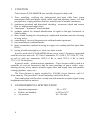
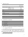
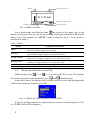
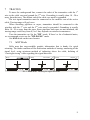
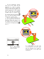
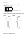
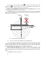
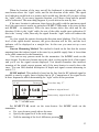
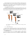
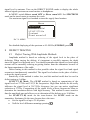
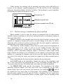
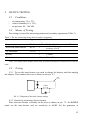
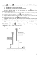
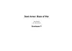
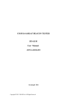
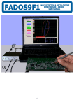
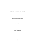
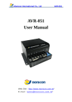
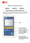
TRACE-LOCATOR
P-410 MASTER
USER’S MANUAL
SVPRIBOR
2
CONTENTS
1 FUNCTION _______________________________________ 4
2 ENVIRONMENTAL SPECIFICATION__________________ 4
3 SPECIFICATION __________________________________ 5
4 SUPPLIED ACCESSORIES __________________________ 5
5 PRINCIPLE
OF
OPERATION
and
DEVICE
CONSTRUCTION _________________________________________ 5
5.1
5.2
6
PREPARING TO WORK _____________________________ 6
6.1
6.2
6.3
7
Defect Tracing With Amplitude Methods _______________15
Defect tracing in insulation by phase method ____________16
Defect tracing in coat insulation of FOL ________________18
Short-circuit in Cable Core Tracing ___________________18
Defining interrupts in cable core ______________________18
Defining interrupts in ropes or pipelines ________________18
DEVICE TESTING ________________________________ 19
9.1
9.2
9.3
9.4
10
11
12
13
MAP Mode _______________________________________9
LEVEL Mode ____________________________________11
Trace search at the bottleneck of supply lines____________12
Branch Lines Search _______________________________14
SPECTRUM mode ________________________________14
DEFECT TRACING _______________________________ 15
8.1
8.2
8.3
8.4
8.5
8.6
9
Getting started _____________________________________6
LCD and Menu ____________________________________7
Sensitivity and Auto-sensitivity _______________________8
TRACING ________________________________________ 9
7.1
7.2
7.3
7.4
7.5
8
Principle Of Operation ______________________________5
Device Construction ________________________________6
Conditions _______________________________________19
Means of Testing _________________________________19
Testing __________________________________________19
Depth measuring tuning ____________________________20
SHIPPING and STORAGE ________________________
PRECIOUS METALS ____________________________
WARRANTY ___________________________________
TEST CERTIFICATE ____________________________
22
22
22
22
3
1
FUNCTION
Trace-locator P-410-MASTER was carefully designed to help with:
1) Trace searching, verifying the underground and open cable lines (open
transmission lines) and power cables; metal cords and pipelines (water-, oil- and
gas pipelines); supply pipelines that have metallic coat or metallic conductors;
2) continuous positional and directional checking, occurrence depth and current
flow in underground supply lines;
3) “maximum”- “minimum” search method;
4) guidance control for channel-identification of signal in line/pipe bottleneck or
cable bundles;
5) direct sound locating for orientating in complicated situations and trace-locating
of noisy wires;
6) controlling of received frequencies in wideband mode (spectrum);
7) trace-searching in wideband mode;
8) phase (contactless) method of tracing in copper wire coating and fiber optic links
(FOL);
9) tracing of cable interruption or cable core short circuits.
In active mode the P-410-MASTER allows you to verify 3-frequency signal and
could be used as a unit with TC-310А-2 transmitter, TC-210А-2, TC-210А, TC-21А,
as well as with any transmitter 6562,5 ± 1 Hz or (and) 2187,5 ± 1 Hz or (and)
273,5 ± 0,5 Hz frequency.
In passive mode – without using a transmitter – Trace-locator could be used as a
controller of received frequencies and for trace-searching of power cables, tracelocating of noisy wires, massive metallic supply lines, and supply lines with metallic
coating (pipelines, ropes, etс.).
The Trace-Locator is power supplied by 4-Ni-Mh A-type batteries with 2,3
А/hrs capacity. This provides 13-hour continuous work of the device.
Trace-indication could be done visually and with acoustic reception signal (using
headphones and built-in emitter).
2
ENVIRONMENTAL SPECIFICATION
•
•
•
4
Operation temperature
Relative air humidity
Air pressure
−20 ÷ +50оС
to 90% at 30оС
86 ÷ 106 kPa
3
SPECIFICATION
Active Frequency
Bandwidth Amplitude –3 dB (≤)
for frequency 6562,5 Hz
for frequency 2187,5 Hz
for frequency 273,5 Hz
Depth
Depth Measurement Accuracy
Trace location accuracy
Trace locating of insulation interruption with transitional
resistance1
Spectrum Frequency Range
Battery life (continuous operation)
Battery Type
Charging Time (≤)
Dimensions
Weight (with the battery)
4
45 Hz
15 Hz
2,5 Hz
6m
±5%+10 cm
10 cm
0 – 100 kOhm
10 ÷ 20 000 Hz
13 h
4-Ni-Mh АА
type , 2,3 A/h.
4h
257х88х685 mm
1,9 kg
SUPPLIED ACCESSORIES
№
1.
2.
3.
4.
5.
5
6562,5 ± 1 Hz
2187,5 ± 1 Hz
273,5 ± 0,5 Hz
Name
P-410-MASTER
Charge adapter 12 V, 0.5 A
User’s manual
Headphones
Headphones Bag
Pieces
1
1
1
1
1
PRINCIPLE OF OPERATION and DEVICE CONSTRUCTION
5.1
Principle Of Operation
P-410-MASTER Trace Locator is a signal receiver for searching of underground
lines, their depth and signal current, and also the locating of cable interruption.
In active search mode (“Map”, “Level”, “LF-HF 273 Hz” or “Phase 6 kHz”
modes) transmitter is the source of the sound frequency signal that being connected to
core of the searched cable. Alternating current produces a magnetic field that induces
1
Amplitude and phase (contactless) methods.
5
a signal in the receiver inductive sensor. Sensors are located in the upper and lower
parts of the receiver. Signals induced in the sensor then come into the receiving
device where analog and digital processing is being done. Then the results are
displayed on the LCD and sound emitter.
In passive mode (”SPECTUM” mode) the receiver is being registered as an
alternating magnetic field in frequency sound range with the source in the power
cable with power current and noisy wire nets.
5.2
Device Construction
The device was constructed as a monoblock. You
can see the device in the pic.5.1. In the upper panel there
are:
•
•
and
Keys of sensitivity
LCD Display
•
- ON /OFF Menu Key
•
- Function Key
АВТО
In the lower panel there are:
•
•
•
- ON/OFF Key
Headphones Outlet
AC/DC Adaptor Outlet
The 4-AA batteries compartment locates in the side
face of the device.
Pic.5.1. General view
6
PREPARING TO WORK
6.1
Getting started
Carefully unpack the trace-locator and make sure it doesn’t have any visible
mechanical damages of the case. If the device has been stored at hyper humidity or at
low temperatures, wait for 24 hours before starting off.
•
6
KEEP OUT WATER
The Trace-Locator is power supplied by 4-Ni-Mh A-type batteries with 2,3
А/hrs capacity. This provides 13-hour continuous work of the device.
Open the battery compartment under the lower panel of the device and insert the
batteries in the correct direction by aligning the “+” and “–“ marks on the batteries
with the polarity markings inside the battery compartment.
•
BEFORE USING MAKE SURE THE BATTERIES ARE
FULLY CHARGED, IF NECESSARY PLUGS THE DEVICE IN!
•
KEEP THE BATTERIES AWAY FROM THE DEVICE TO
AVOID THEIR DAMAGE
Connect the AC power adaptor to the trace-locator and fully charge the batteries.
The process of charging is displayed on the LCD. You can’t put the device on by the
when being charged.
New batteries require 10-12 full charge-discharge cycles to obtain maximum
level of capacity. The charger indicates the level of operability of the batteries overcharged or defective batteries wouldn’t be charged.
Every time before tracing the batteries should be charged.
Before long-time storage or transporting charge the batteries in order to avoid
their damage and take them out of the compartment.
. If it is properly connected, then it’s serial number and
Turn the device ON
software version will be displayed. The Menu comes on as shown in pic.6.1.
M enu
Mаaрpт а
К
Level
Sp e c tr u m
Phase 6 kH z
L F -H F 273 H z
Pic. 6.1. MENU
When the battery is low, the device turns off.
6.2
LCD and Menu
Before using the trace-locator choose/set the mode. To change/set the mode use
АВТО
MENU. Enter the MENU using
as shown in pic.6.1.
MENU appears on the display. To change modes press
АВТО
from the set menu press
and
. To exit
.
7
M od e
fun ctio na l k ey “ F ”
D e pt h
Map
F
h = 9 см
7 0 dB
S e ns itivity sc ale
B a ttery c ha rg e le ve l
S e ns itivity, d B
Pic.6.2. DISPLAY PANEL
Every mode name and function name
are shown in the upper line on the
display, in the lower line you can see the meaning of the gain controller in dB and the
battery level. The example of “LEVEL” mode is shown in pic.6.2. Every mode is
described in Table 1.
Table 1. MENU
Modes
Available Measurements
“MAP”
“LEVEL”
“LF-HF 273 Hz”
“PHASE 6 kHz”
“SPECTRUM”
“Direct sound off”
6.3
Frequency Signal Level 2187,5 Hz
Direction, Position, Signal Current, Depth
Frequency Signal Level 2187,5 Hz
Signal Current, Depth, Minimum and Maximum Modes
Frequency Signal Level 273,5 Hz
Difference of Frequency Signal Level 273,5 Hz and 2187,5 Hz
Frequency Signal Level 6562,5 Hz
Difference of Signal Phases 2187,5 Hz and 6562,5 Hz
Received Signal Spectrum - Energo (10-500 Hz) and Wide (10-20000 Hz)
Turn ON the “Direct sound” in SPECTRUM mode
Sensitivity and Auto-sensitivity
When tracing, press
(<) or
(>) to set the signal level up to 70-80 points.
and
simultaneously.
To set the required level automatically, press
In the lower line of the display you’ll see the sensitivity scale with grating period
2 dB and the meaning of sensitivity in dB.
Pic 6.9. DISPALAY INDEX WHEN OVERLOADED
If there’s a background noise, high sensitivity causes corrupted signal level. If
so, OVERLOAD will be displayed.
8
7
TRACING
To trace the underground line, connect the outlet of the transmitter with the 1st
wire to the cable core and ground the 2nd wire. Grounding is usually done 10 - 20 м
away from the trace. The distant end of the cable core must be grounded.
The test signal transmitter must be connected to the metallic coat of the active
cable. Tracing range will get lower.
When searching pipelines or ropes, transmitter should be connected to the
pipeline with the 1st wire and the 2nd wire must be grounded. Grounding is usually
done 10 - 20 м away from the trace. Since pipelines and ropes are not insolated, the
tracing range could vary from 0,2 to 5 km, depends on curtain circumstances.
Turn the transmitter on. Set the “HF” mode. If there’s a lot of industrial noise,
we recommend you to use the “HF-PAUSE” mode.
Set MAP mode on the trace-locator.
7.1
MAP Mode
Cable map has easy-readable graphic information that is handy for quick
orienting. The mode combines all the innovation methods of tracing: measuring of the
signal level, using minimum method of indicating above the cable, defining of
“own/right-wrong” cable regarding the signal direction.
Map
Map
7 0 dB
D ire c tio n
F
Map
7 0 dB
D e pt h
F
7 0 dB
Pic.1. MAP Mode. Defining the signal direction
9
Do the preliminary tracing.
The level of the signal will be
displayed as a line or pointer.
When you get the firm signal, the
direction of the cable signal current
will be defined in a few seconds
(Pic 1,a), but the level indicator
wouldn’t look as a pointer. Settle
SYRIAN TELECOM
Карта
the required direction pressing
(Pic. 1,b), then the indicator will be
displayed as a pointer again.
Pic. 2, shows the position of
the trace-locator above the trace as
displayed. When the pointer is in
the middle of the cross-point, you
can measure the depth pressing
(Pic. 3).
Глубина
F
34 dB
SENSITIVITY
SVPRIBOR
MENU
P- 410-MASTER
.
I
SYRIAN TELECOM
Карта
Глубина
F
34 dB
SENSITIVITY
SVPRIBOR
Map
D e pth
MENU
P- 410-MASTER
F
I
7 0 dB
Рic 3. The position
when measuring of the
depth is available.
10
Pic. 2. Cable MAP, а – the “right” cable
is on the right side of the device: signal
from the transmitter goes straight on
through the cable; b – the “right” cable
is on the left.
7.2
LEVEL Mode
Use LEVEL mode to define the trace with permanent digital monitoring of the
signal level with 2187,5 Hz frequency, depth and signal current2.
Set LEVEL mode on the trace-locator.
maximum
55
MIN F
Function key “F”
h = 11 см
Depth
I = 1,0
Signal current
Frequency signal level 2187,5 Hz
36 dB
Pic. 4. LEVEL mode
Do tracing at maximum signal level. Maximum method of indicating helps you
to determine approximate trace location. To gain more accurate measurement, use the
minimum method mode.
Pic. 5. Dependence of the signal level on the trace-locator position and the search
mode
2
At weak signal, depth and signal current are not displayed
11
Every mode name and function name
are shown in the upper line on the
display. Press to switch the mode off. You can see dependence of the signal level
on the trace-locator position and the search mode in Pic.5.
When tracing at minimum method mode, follow the minimum signal level. This
mode helps you to determine exact trace location.
At LEVEL mode the trace with permanent digital monitoring of the depth and
signal current are displayed. This measurements are correct at exact point of the tracelocator above the line (pic. 6).
a ) correct
measuring
b) incorrect
measuring
ground
h
underground line
Pic. 6. Depth and signal current measuring
7.3
Trace search at the bottleneck of supply lines
At the bottleneck of supply lines the signal is received both from the cable,
connected to the transmitter and from parallel supply lines. To trace the right cable
different methods could be used. We recommend you to do the tracing connecting to
the grounded distant end of the cable core. Turn the transmitter on.
Current Direction Method. This method is based on the principle of the
reverse current direction in the parallel supply lines. For this method permanent mode
of the signal generation in the transmitter is preferable but you can also use any other
mode.
Set MAP mode on the trace-locator.
12
When the location of the trace out-off the bottleneck is determined, place the
trace-locator above the “right” cable, and fix the direction of the cable. The signal
level indicator would look as a pointer and it would stay like this till you move along
the “right” cable. If you move opposite direction, you’ll hear a beep and the pointer
will be redirected. The same thing happens if you switch to the near-by line.
If the trace location is unknown, then choose the cable with the maximum signal
level (the most correct results are gained at LF-HF 273 Hz mode in the trace-locator
and LF-HF – in transmitter). Place the trace-locator above this cable and fix the
direction. If this is the “right” cable, the rest of the cable would cause redirection. If
this is the “wrong” cable, then only the signal from the “right” cable will redirect the
pointer.
At a low signal the pointer showing the direction starts blinking. If in 30 sec the
level of the signal doesn’t increase, the given direction will be lost, and the level
indicator will be displayed as a straight line. In this case you must set up a new
direction.
Current Measuring Method. This method is based on the fact that the current
meaning from the induced signal in the near-by or parallel supply lines is lower than
in the cable connected to the transmitter.
You can use any process mode for the transmitter. Set LEVEL mode on the
trace-locator. Fix the trace-locator above the cable, set the regular level of the signal,
and you’ll see the signal current displayed. You should remember that incorrect
meaning of the signal current appears only if the trace-locator is exactly above the
trace. You can find detailed description of depth and signal current measuring in
article 7.2.
LF-HF method. This method is based on the fact that the HF induced signal in
parallel or near-by supply lines is higher that in LF. Comparison of the signal levels
at these frequencies allows determining the “right” cable at fine precision.
L F -H F
R e se t
69 15dB
F
F u nc tion key “F ”
D e fe re nt sign al le vel
F req ue ncy sign al le vel 27 3 H z
3 6 dB
Pic. 7.7. LF-HF mode.
Set LF-HF 273 Hz mode on the trace-locator. Set LF-HF mode on the
transmitter.
• Fix trace-locator exactly above the trace.
• Specify the signal level in the scale range.
•
Null the meaning of the level difference pressing
.
13
Moving along the trace, the meaning of the level difference will be progressively
increasing (a few dB by 100 m) because of different or unequal signal propagation at
273 Hz and 2187,5 Hz frequencies in the cable. Big difference increase will be
displayed when a “wrong” cable is detected. The meaning is correct regardless of
switching the modes till the device is off.
7.4
Branch Lines Search
Set LEVEL mode on the trace-locator. Do tracing as described in article 7.1. Do
the branch lines searching setting the trace-locator parallelly the trace as shown in
pic.7.8. In this case the signal level from the “right” cable is minimum (Pic 7.8.b),
and the branch lines will cause big increase of the signal level (Pic 7.8.в).
maximum
MIN F
h = 11 см
80
а) tracing
I = 1,0
36 dB
б)branch lines searching
maximum
MIN F
h = 11 см
10
I = 1,0
36 dB
в) branch line is detected
maximum
MIN F
h = 11 см
80
I = 1,0
36 dB
branch line
trace
Pic.7.8. Branch lines searching: а) tracing, б) branch lines searching, в) branch
line is detected
7.5
SPECTRUM mode
In passive mode – without using a transmitter – Trace-locator could be used as a
controller of received frequencies and for trace-searching of power cables, tracelocating of noisy wires, massive metallic supply lines, and supply lines with metallic
coating (pipelines, ropes, etс.).
Set SPECTRUM mode on the trace-locator. You’ll see signal spectrum
displayed in the frequency range at 10 ÷ 20 000 Hz (WIDE). Permanent frequency
signal will be displayed on the sound emitter or headphones according to induced
14
signal level in antenna. Turn on the DIRECT SOUND mode to display the whole
induced signal spectrum on sound emitter or headphones.
In MENU switch Direct sound OFF to Direct sound ON. Set SPECTRUM
mode on the trace-locator to continue the work.
Use maximum signal level method to trace the supply lines location.
Menu
Sp e c tr u m
PHA SE 6 kHzl
L F -H F 2 7 3 H z
C o n tra s t
D ire c t s o u n d o ff
Pic 7.9. MENU
For detailed displaying of the spectrum at 10-500 Hz (ENERGO) press
8
.
DEFECT TRACING
8.1
Defect Tracing With Amplitude Methods
Amplitude method is based on reducing of the signal level in the place of
defecting. When tracing the defects, it’s important to carefully measure the depth
since the signal level depends on it. You should remember that signal level and signal
current will be smoothly reducing as getting further from the transmitter because of
the linear capacitance of the cable.
Defect tracing in this method is also possible when the signal level and signal
current are simultaneously controlled. The signal level reduces in the place of defect,
so does the signal current.
Sensitivity of the method is rather low, and this method could also be used in
defect tracing at 1 кOhm.
LF-HF 273 Hz Mode. The LF-HF method is based on comparising of the
signal levels at 273 Hz and 2187,5 Hz frequencies. High-Ohm defects do not really
influence the signal level at 2187,5 Hz frequency but you can notice significant
reduction at 273 Hz. Comparising of the signal levels at these frequencies allow to
determine the insulation defects with high accuracy. This method is more sensitive
than the amplitude one and allows you to determine all the defects up to 10 kOhm.
Set LF-HF 273 Hz mode on the trace-locator. Set LF-HF mode on the
transmitter. Stationary fix the trace-locator above the trace.
• Set the signal level up to 70-80 points.
•
Null the level difference meanings pressing
.
15
While tracing, the meaning will be smoothly increasing (a few dB by100 m),
because of the unequal signal propagation at 273 Hz and 2187,5 Hz. Significant
difference increasing displays the place of defect. The meaning is correct regardless
of switching the modes till the device is off.
LF-HF
Reset F
69 15dB
Function key “F”
Difference signal level
Frequency signal level 273 Hz
36 dB
Pic. 8.1. LF-HF 273 Hz mode
8.2
Defect tracing in insulation by phase method
Phase method is used to trace the defects in insulation coat of cables where
metallic coating is missing, as well as for tracing the defect in insulation coating of
fiber optic links (FOL).
Method is based on the principle that before the defect location, current in cable
consists of capacitive current and resistive current leakage in the place of defect.
When the place of defect is passed, current in cable has only capacitive constituent,
and the phase of the signal current changes. Pic 8.2.
The sensitivity of this method is lower than at contact method and depends on
linear capacitance of the cable, as well as on the leakage location. The lower
cumulative capacity in a certain piece after leakage of cable is, the higher the
sensitivity will be. Maximum sensitivity equals 10 deviation in phase signal which
helps to define the leakage up to 50 kOhm at 100 nF capacity in a certain piece after
leakage. It’s important to remember that at this level the signal reduces and at the
very end of the cable the meter may point low signal level where method doesn’t
work.
Keep controlling the deviation in phase signal in the pre-taken trace.
Set LF-HF mode on the transmitter. Connect the outlet of the transmitter with
the 1st wire to the cable core and ground the 2nd wire. Grounding is usually done 10 20 m away from the trace. The distant end of the cable core must be insolated.
Set PHASE 6 kHz mode on the trace-locator. The meaning of the phase
difference between signals 2187,5 Hz and 6252,5 Hz is displayed. Fix the traceand set
locator firmly above the trace choose the sensitivity level pressing or
the signal level not lower than at 70-80 points. The meaning of the difference
between phase signals 2187,5 Hz and 6252,5 Hz is displayed. At low signal level
there’s a possibility of measurement failure of phase signal. Null the meaning of the
16
phase pressing . “0 deg” readout must be stable. If it’s not possible to set “0 deg”,
it means that the noise level is excessive. So you can’t apply the phase method of
defect tracing.
Phase
Reset
F
Phase deg.
55
0
Phase
Reset
F
Phase deg.
36 dB
55
10
36 dB
Itransmitter
Itransmitter
IC
IR
IC
IC-capacitive current
IR-resistant current (defect current)
Defect
Pic. 8.2. Defect tracing by phase method
Phase
Reset F
Function key “F”
Phase deg.
9
15
Phase
Frequency signal level 6562,5 Hz
70 dB
Рисунок 8.3. PHASE 6 kHz mode
To locate the defect moving along the trace do measuring of phase difference.
The meaning of the difference will be progressively increasing (a degree unit by 100
m), because of different or unequal signal propagation at 273 Hz and 2187,5 Hz
frequencies in the cable. Significant difference increase will be displayed when a
defect is detected. To update the defect locations go back to the previous position and
re-measure.
At”20 deg.” level you’ll hear a beep.
17
8.3
Defect tracing in coat insulation of FOL
To trace low-Ohm defects amplitude method is the most appropriate (effective).
In complicated cases phase and HF-LF methods could be used. Defect tracing in
coat insulation of FOL is implemented when moving along the trace and similar to
defect tracing in copper cable insulation. Also remember that in this case all the
mentioned methods are less sensitive because linear capacity of the FOL coating is
much higher than in the copper cable. As a rule sensitivity ≤ kOhm units.
8.4
Short-circuit in Cable Core Tracing
Connect the transmitter to the defective cable core. It’s recommended to work on
the shortest piece of cable to reduce spurious signal through the cable capacity.
Preferably to locate the defect closer to the distant end of the cable located aside from
the transmitter.
Short-circuit is defined by the sharp decreasing of the signal level so make sure
to control the depth. You can also define short-circuit by decreasing the signal
current.
The most correct results are gained at LF-HF 273 Hz mode in the trace-locator
and LF-HF – in transmitter but you should remember that the signal level in this case
will be much lower. That’s why you should firstly use MAP or LEVEL mode and
then locate the defects in LF-HF 273 Hz mode.
8.5
Defining interrupts in cable core
Connect the outlet of the transmitter with the 1st wire to the поврежденной cable
core and ground the 2nd wire. Grounding is usually done 10 - 20 m away from the
trace. The distant end of the cable core must be insolated.
Interrupt zone in amplitude method is defined by sharp decreasing of the signal
level or current level in LEVEL mode.
Specify the place of interruption at low frequency. Set LF-HF 273 Hz mode on
the trace-locator. Set LF-HF mode on the transmitter but remember that the signal
level will be much lower.
8.6
Defining interrupts in ropes or pipelines
Since the insulation in pipelines and ropes coating is missing, the transmission
range may vary between 0,2 to 5 km and also depends on certain conditions.
Interruption in ropes or pipelines is defined by the same method as in the core cable.
18
9
DEVICE TESTING
9.1
−
−
−
9.2
Conditions
air temperature 20 ± 2°С;
relative humidity 65 ± 15%;
air pressure 84 – 106 kPa.
Means of Testing
For testing you need the measuring means and secondary equipment (Table 2).
Table 2. The list measuring means and secondary equipment
Name
Type
Frequency meter
Ч3-64
Wide-band Millivoltmeter
В3-59
LF Transmitter
Г3-118
Quantit Main Characteristics
y
1
20 Hz – 20 кHz accuracy 1х10-5
1 mV - 300 V
1
accuracy 0,2х10-2
1
Resistor
1
1 kOhm
Wire
10m
Wire 0,75mm2
Notе: For testing other sample means with relevant metrological characteristics could be
used.
9.3
Testing
9.3.1. To test the trace-locator you need to charge the battery and then unplug
the adapter. Then connect the wire as shown in the pic. 9.1.
wire
Г3-118
1 kOhm
Pic. 9.1. Diagram of the trace-locator testing
9.3.2. Sensitivity measuring of trace-locator
Place the trace-locator vertically on the wire as shown in pic. 7.2. Set LEVEL
mode on the trace-locator and set sensitivity at 44 dB. Set the generator at
19
2187,5 Hz±0,5 Hz and output signal level at 70 points. The resistor voltage measured
with millivoltmeter must be at 200 mV.
Set PHASE 6 kHz mode on the trace-locator and sensitivity at 44 dB. Set the
generator at 6562,5 Hz±1 Hz and output signal level at 70 points. The resistor voltage
measured with millivoltmeter must be at 2 V.
Set LF-HF 273 Hz mode on the trace-locator and sensitivity at 44 dB. Set the
generator at 273,5 Hz±0,5Hz and output signal level at 70 points. The resistor voltage
measured with millivoltmeter must be at 1 В.
9.3.3. Frequency of maximum measuring
Set LEVEL mode on the trace-locator, on the generator Set the generator at
2187,5 Hz±0,5 Hz and set sensitivity on the trace-locator at 50-90 points, changing
the frequency define the maximum meaning of the signal level. The defined
frequency measured with the frequency meter must fit the meaning in Table 3.
Set PHASE 6 kHz mode on the trace-locator, on the generator Set the generator
at 6562,5 Hz and set sensitivity on the trace-locator at 50-90 points, changing the
frequency define the maximum meaning of the signal level. The defined frequency
measured with the frequency meter must fit the meaning in Table 3.
Set LF-HF 273 Hz mode on the trace-locator, on the generator Set the generator
at 273,5 Hz and set sensitivity on the trace-locator at 50-90 points, changing the
frequency define the maximum meaning of the signal level. The defined frequency
measured with the frequency meter must fit the meaning in Table 3.
9.3.4. Bandwidth calibration is measured by level –3dB. To do this the signal
level must be set at 70 points of the frequency of maximum, then at permanent signal
level of the generator you must first increase the frequency to gain 50 points; then
decrease it to gain the same point. The difference between upper and lower meanings
of frequency defines the bandwidth that must fit the meaning in Table 3.
Table 3.
Active frequency, Hz:
LEVEL mode
PHASE 6 кHz mode
LF-HF 273 Hz mode
Bandwidth Amplitude –3 dB (≤)
LEVEL mode, 2187,5 Hz
PHASE 6 кHz mode, 6562,5 Hz
LF-HF 273 Hz mode, 273,5 Hz
9.4
2187,5 ± 1
6562,5 ± 1
273,5 ± 0,5
15 Hz
45 Hz
2,5 Hz
Depth measuring tuning
Before running of the device, in order to gain the maximum frequency you may
tune the depth measuring.
To tune the device you need a separate cable with the certain (known) depth - h.
Locate and tag the point above the cable center. Turn on tune mode on the device
20
pressing
and press
at the same time. In this mode MENU will display
additional points:
1. SET DEPTH – Depth Tuning Function
2. DEFAULTS – Restore Factory Settings Function
АВТО
then follow
Set SET DEPTH mode on the trace-locator and press
instructions displayed on LCD:
1. “Set the device above the trace and press “OK” – set the device vertically at the
АВТО
tag point above the trace (Pic 9.2.а.), press . Tuning takes about 5 sec.
2. “Lift up the device at 50 sm and press “OK” – lift up the device 50 sm above the
АВТО
tag level vertically (Pic 9.2.b), press . Tuning takes about 5 sec.
When the tuning is done, the trace-locator will be working on personal setting.
Set LEVEL mode on the trace-locator and make sure that the displayed depth
meaning matches the known depth - h.
If necessary, you may go back to factory settings. In MENU choose
АВТО
Confirm
using
DEFAULTS
and
press .
“DEFAULTS YES →NO», вchoosing “YES”.
3.
a.
the
factory
settings
b.
lift up the de vic e
50 сm above the ta g
level v ert ica lly
set the de vic e
vertic ally at the
tag point abov e
the trace
h+50 см
h
Trace
Pic 9.2. Trace-locator position when tuning the depth
21
10 SHIPPING and STORAGE
For shipping trace-locators must be done carefully packed according to the
shipping rules and regulations.
•
BEFORE LONG-TIME SHIPPING TO AVOID THE
DAMAGE TAKE THE BATTERIES OUT
•
BEFORE LONG-TIME STORAGE THE BATTERIES
MUST BE FULLY CHARGED
WARNING! Make sure that the condition in the storage rooms or warehouses
satisfy the requirements for storing the devices and doesn’t have any dust, aggressive
gas, acids or harmful crud that could cause rusting!
11 PRECIOUS METALS
The device does not include any precious metals
12 WARRANTY
Manufacturer guarantees operating capacity of the trace-locator within the
warranty period only if all the required operating, storage, shipping conditions are
carefully observed.
Warranty period - 24 months from the sale date.
Warranty does not cover the battery and charger.
Manufacturer Address:
RUSSIA,
POBox 43100
SVPRIBOR
170043, TVER
tel: +7-4822- 41-29-91, 72-52-76, 51-50-72
fax: +7-4822- 41-29-91
E-mail: [email protected]
http://www.svpribor.ru
13 TEST CERTIFICATE
P-410-MASTER, S/N ___________satisfies all the technical conditions and
admitted and fits for service.
Manufacture Date “___”________2008
Factory Representative (signature) _________
22