1
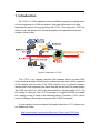
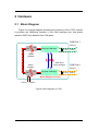
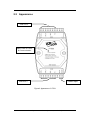
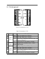
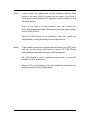
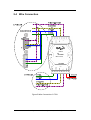
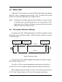
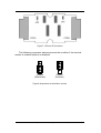
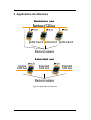
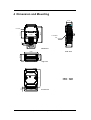
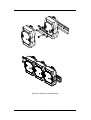
The i-7531 CAN Repeater
User’s Manual
Warranty
All products manufactured by ICP DAS are under
warranty regarding defective materials for a period of one
year from the date of delivery to the original purchaser.
Warning
ICP DAS assumes no liability for damages resulting
from the use of this product. ICP DAS reserves the right to
change this manual at any time without notice. The
information furnished by ICP DAS is believed to be
accurate and reliable. However, no responsibility is
assumed by ICP DAS for its use, or for any infringements
of patents or other rights of third parties resulting from its
use.
Copyright
Copyright 1997 by ICP DAS. All rights are reserved.
Trademark
The names used for identification only may be
registered trademarks of their respective companies.
i-7531 CAN Repeater User Manual (ver. 1.1, 2008/01/10) ------1
Tables of Content
Tables of Content...........................................................................................2
1 Introduction.............................................................................................3
1.1 Features..........................................................................................4
1.2 Specifications.................................................................................4
2
1.3 Application .....................................................................................4
Hardware .................................................................................................5
2.1 Block Diagram................................................................................5
2.2 Appearance ....................................................................................6
2.3
2.4
2.5
3
4
Pin Assignment..............................................................................7
Wire Connection ............................................................................9
Status LED....................................................................................10
2.6 Terminator resistor settings .......................................................10
2.7 Cable selection ............................................................................12
Application architecture.......................................................................13
Dimension and Mounting .....................................................................14
i-7531 CAN Repeater User Manual (ver. 1.1, 2008/01/10) ------2
1 Introduction
The i-7531 is a CAN repeaters used to establish a physical coupling of two
or more segments of a CAN bus system. User can implement tree or star
topologies as well as for long drop lines with i-7531. Connecting via i-7531, the
division of a CAN system into several subsystems increases the maximum
number of bus nodes.
Figure1. Application of i-7531
The i-7531 is an optically isolated CAN repeater which provides 2500
Vrms of optical isolation allowing you to separate and protect critical segments
of the system from the rest of the CAN network. And its galvanic isolation
isolates both CAN segments from each other as well as from the power supply
The CAN connection of i-7531 is by terminal blocks. A power supply of 10 ~ 30
DC voltage is required. The i-7531 is housed in a rugged DIN-Rail mountable
box, making it easy to install in an industrial cabinet. Therefore, i-7531 can be
used in CANopen, DeviceNet and generic ISO 11898-2 standard.
If user wants to know more detail information about the i-7531, please visit
our website as follow:
http://www.icpdas.com/products/Remote_IO/can_bus/i-7531.htm
i-7531 CAN Repeater User Manual (ver. 1.1, 2008/01/10) ------3
1.1 Features
High speed (up to 1 Mbps)
Removable terminal block
Mountable on DIN Rail
Bus pins protected against transients in an industrial environment
No disturbance of the bus lines with an un-powered node
Transmit data (TxD) dominant time-out function prevents the output
drivers from driving a permanent dominant state
A thermal protection circuit is integrated to prevent the transceiver
from damage if the junction temperature exceeds thermal shutdown
level.
1.2 Specifications
Support CAN 2.0A/CAN 2.0B
Fully compatible with the ISO 11898-2 standard
Communication baud range : 10Kbps ~ 1Mbps
Photo-coupler isolation between 2 CAN port: 2500 Vrms
Power consumption: 2W max
CAN terminal resistors are integrated (can be disabled by jumper)
3KV galvanic isolated among of power supply and each CAN port
Power Supply: +10VDC ~ +30VDC
Operating temperature: -25°C ~ +75°C
Humidity: 5% ~ 95%
Dimensions: 123 mm x 72 mm x 33 mm
1.3 Application
Factory Automation
Building Automation
Home Automation
Control system
Monitor system
Vehicle Automation
…
i-7531 CAN Repeater User Manual (ver. 1.1, 2008/01/10) ------4
2 Hardware
2.1 Block Diagram
Figure 2 is a block diagram illustrating the functions of the i-7531 module.
It provides the 3000Vrms isolation in the CAN interface site. And photoisolation 2500 Vrms between two CAN ports.
CAN Port 1
CAN_H
DC
DC
Physical CAN layer
120 Ohm
CAN_L
3000V
Isolation
3000V
Isolation
DC
DC
2500 Vrms
Photo Isolation
CAN Port 2
CAN_H
Physical CAN layer
120 Ohm
CAN_L
Block Diagram of I-7531
+10VDC ~ +30VDC
Figure2. Block diagram of i-7531
i-7531 CAN Repeater User Manual (ver. 1.1, 2008/01/10) ------5
2.2 Appearance
CAN Port 2
Status LED of Power
& Communication
CAN Port 1
Power Input
Figure3. Apperance of i-7531
i-7531 CAN Repeater User Manual (ver. 1.1, 2008/01/10) ------6
2.3 Pin Assignment
Figure4. Pin assignment of i-7531
Table1. Pin description of i-7531
No.
Part
Name
1
3
5
CAN
Port 1
7
9
10
14
16
18
20
CAN_L
CAN_Low. Signal Line of CAN port 1.
CAN_H
CAN_High. Signal Line of CAN port 1.
GND
FG
Power
Input
CAN
Port 2
Description
(R)VS+
CAN_Ground, Voltage level of ground of CAN_L and
CAN_H of CAN port 1.
Frame Groud (or CAN_Shield) of CAN port 1.
Voltage Source. It could be +10VDC ~ +30VDC。
(B)GND Power Ground.
CAN_L
CAN_Low. Signal Line of CAN port 2.
CAN_H
CAN_High. Signal Line of CAN port 2.
GND
FG
CAN_Ground, Voltage level of ground of CAN_L and
CAN_H of CAN port 2.
Frame Groud (or CAN_Shield) of CAN port 2.
i-7531 CAN Repeater User Manual (ver. 1.1, 2008/01/10) ------7
Note1:
In some cases, the voltage level of CAN_Ground of different CAN
device in the same CAN bus system are not equal. At this time, it
could cause some problems to derogate system staibility of this
CAN bus system.
There is one way to fix this problem; user can connect the
CAN_Ground between those CAN devices to achieve equal voltage
level of CAN_Ground.
Wiring of CAN_Ground is not necessary; user can modify the
configuration of wiring according to actual applications.
Note2:
If user usees some kinds of signal cable with shield (e.g. STP), then
user can use the shield of this cable to connect FG (CAN_Shield)
among different devices in the same CAN bus system.
FG (CAN_Shield) is used to shield the signal cable, to avoid RF
radiation or other interference.
Wiring of FG is not necessary; user can modify the configuration of
wiring according to actual applications.
i-7531 CAN Repeater User Manual (ver. 1.1, 2008/01/10) ------8
2.4 Wire Connection
Figure5. Wire Connection of i-7531
i-7531 CAN Repeater User Manual (ver. 1.1, 2008/01/10) ------9
2.5 Status LED
When the i-7531 is turned on, the status LED will be display with red light.
Moreover, when a message passes through i-7531, the status LED will be
twinkle once with yellow light while the red light is still on.
Note3: Twinkling rate correlates with baud rate of CAN bus. Users may see
no twinkling when the twinkling period is too short because of the
higher baud rate of CAN bus. Besides, the yellow LED could look like
always on when bus loading is heavy.
2.6 Terminator Resistor Setting
According to the ISO 11898 specifications, the CAN bus network must be
terminated by two termination resistor (120Ω) for proper operation, as shown
in the below figure.
Device 1
Device 2
.
.
.
Device 127
CAN_H
CAN_L
Figure6. Terminator resistor
Therefore, the i-7531 module supplies two switches for users to connect
the terminator resistor or not.
The JP2 of i-7531 is used for adjusting terminal resistor on CAN Port 1,
and the JP3 of i-7531 is used for adjusting terminal resistor on CAN Port 2.
Before adjusting terminal resistor of i-7531, user needs to open the cover
of i-7531 first. Those locations of JP2 and JP3 are shown as following:
i-7531 CAN Repeater User Manual (ver. 1.1, 2008/01/10) ------10
Figure7. JP2 and JP3 positions
The following connection statuses present the condition if the terminal
resistor is enabled (default) or disabled.
Disable
(Deactivate)
Enable
(Activate)
Figure8. Adjustment of terminator resistor
i-7531 CAN Repeater User Manual (ver. 1.1, 2008/01/10) ------11
2.7 Cable Selection
The CAN bus is a balanced (differential) 2-wire interface running over
either a Shielded Twisted Pair (STP), Un-shielded Twisted Pair (UTP), or
Ribbon cable. The wire of CAN_L and CAN_H start on one end of the total
CAN network that a terminator resistor of 120 Ohm is connected between
CAN_L and CAN_H. The cable is connected from CAN node to CAN node,
normally without or with short T connections. On the other end of the cable
again a 120Ω (Ohm) terminator resistor is connected between the CAN lines.
How to decide a cable type, cable length, and terminator depends on the baud
rate in the CAN bus network, please refer to the following table.
Table2. Cable selection
Cable
Terminator
resistance/m
Bus speed
Cable type
50k bit/s at 1000m
0.75~0.8mm2
18AWG
70 mOhm
150~300
Ohm
600~1000m
100k bit/s at 500m
0.5~0.6 mm2
20AWG
< 60 mOhm
150~300
Ohm
300~600m
< 40 mOhm
127 Ohm
40~300m
0.25~0.34mm2
< 40 mOhm
23AWG, 22AWG
124 Ohm
0~40m
500k bit/s at 100m
1000k bit/s at 40m
0.34~0.6mm2
22AWG, 20AWG
Bus Length
Note4: The AWG means a standard method used to measure wire. The
numbering system works backwards from what people would think,
the thicker (heavier) the wire, the lower the number. For example: a
24AWG wire is thicker/heavier than a 26AWG wire.
i-7531 CAN Repeater User Manual (ver. 1.1, 2008/01/10) ------12
3 Application Architecture
Figure9. Application architecture
i-7531 CAN Repeater User Manual (ver. 1.1, 2008/01/10) ------13
4 Dimension and Mounting
29.50
2-SCREW
M3
7.30
56.00
8
88.50
35.30
O4.5X4
25.00
40.50
33.00
Back View
72.00
33.00
25.00
Side View
Top View
10.5
111
56.00
58.50
72.00
From View
i-7531 CAN Repeater User Manual (ver. 1.1, 2008/01/10) ------14
Figure10. Dimension and Mounting
i-7531 CAN Repeater User Manual (ver. 1.1, 2008/01/10) ------15