1
PARTICIPANT REGISTRATION
(please print legibly)
COURSE TITLE: MILK PASTEURIZATION CONTROLS AND TESTS, #302
COURSE
LOCATION:
DATE(S):
NAME:
JOB TITLE:
JOB RESPONSIBILITIES:
ADDRESS:
WORK
WORK PHONE NUMBER:(
(
)
HOME
(
)
)
NUMBER OF YEARS IN CURRENT PROFESSION:
DURING THIS COURSE WHICH AREA(S) WOULD YOU LIKE TO HAVE EMPHASIZED?
SPECIFIC QUESTION(S) THAT YOU WOULD LIKE TO HAVE ANSWERED DURING THIS TRAINING
:
1.
2.
3.
STATE TRAINING BRANCH
COURSE MANUAL
8th Edition
2003
Department of Health and Human Services
Public Health Service/Food and Drug Administration
Division of Human Resource Development
State Training Branch
The purpose of this course is to develop and/or increase the
knowledge, skills and proficiency necessary for the inspection
and testing of milk pasteurization equipment. Emphasis is
given to the controls and tests necessary to assure effective
pasteurization of milk and/or milk products . The course is
designed to teach the public health reasons for the
requirements which govern design, function and operation of
milk pasteurization equipment.
4
Richard D. Eubanks, CAPT United States Public Health Service
Training Officer
with edits by Ray Niles
Gary German, Director
Food and Drug Administration
Division of Human Resource Development
State Training Branch
5600 Fishers Lane, (11919 Rockville Pike)
Rockville, MD 20857
Phone (301)827-8697
*************************************************
Note: The use of trade names or equipment photographs is for
training and educational purposes only and does not constitute
endorsement by the Food and Drug Administration.
*************************************************
5
Acknowledgments--The development, preparation, and publication of this course
manual is the responsibility of the State Training Branch, Division of Human
Resources Development, Food and Drug Administration. The updated schematics of
HTST systems were taken from the 3-A Accepted Practices for the Sanitary
Construction, Installation, Testing and Operation of High-Temperature Short Time
and Higher-Heat Shorter-Time Pasteurizer Systems, Revised, Number 603-06. The
National Conference on Interstate Milk Shipments has resolved in their Conference
agreements to fully support the training efforts of the FDA
The requirements and legal aspects found within this manual were taken from
previous editions and printing of this manual and the current edition of the Grade A
Pasteurized Milk Ordinance and acknowledgment is given to all the previous
contributors of that document.
This edition of the training manual was compiled, prepared and edited by
CAPT Richard D. Eubanks, USPHS, Training Officer, FDA/ ORA/DHRD, State Training
Branch with major rewriting of the HHST,UHT Chapter and revisions in other portions
of the testing section. Technical and word processing assistance was provided by CDR
Artis M. Davis, USPHS, Regional Milk Specialist, Southwest Region. Appreciation is
also given to the Regional Milk Specialist, State Rating and Regulatory Officials and
the milk industry for their support and contributions to the development of this
manual. CDR Robert F. Hennes also assisted by providing much needed technical and
grammatical editing. Mr. Steven T. Sims, FDA/CFSAN Milk Safety Branch has also
provided excellent detailed information on the inspection and testing of HHST/UHT
systems. Others contributing technical information are Dr Joseph Schlesser,
FDA/CFSAN/HACCP/Division of Food Processing and Packaging, Mr. Richard Gleason,
California Department of Food and Agriculture and Mr. Roger Krug of the Oregon
Department of Agriculture provided technical suggestions and assistance.
The “RED COW BOOK”, as it is presently known, is to be used as a training and
reference source. It has evolved over the years as a result of previous milk training
officers assigned to FDA’s State Training Branch. It was through the energies of
individuals such as I. H. Schlafman, K. L. Pool, Roger Dickerson, Jr., R. B. Read, Jr.,
Robert B. Carson, Harold (Tommy) Thompson, Harold Faig, Ronald Smith, O.D.(Pete)
Cook, Brenda Holman and others, and under the direction and support of State
Training Branch Directors such as James P. Sheehy, Harry Haverland and Gary E.
German that this manual has developed into its present form. Providing much of the
regulatory and practical aspects of inspecting and testing pasteurization systems
were the FDA Regional Milk Specialists, FDA's Milk Safety Branch, State Milk Rating
Officers, state and local milk regulatory individuals, and the milk industry and
academia who have all contributed to the further development of this training
manual.
6
FOREWORD
This Course is designed primarily for state milk regulatory and rating
personnel, local milk inspection staff, FDA milk specialists and investigation
personnel, elements of the milk industry,(including quality assurance), plant
management, plant engineers, industry consultants, colleges and university
staff and students, military food and milk specialists, and other personnel
engaged and concerned with the safe processing of milk and milk products.
Fundamental principles of the theories and sanitary operation of milk
pasteurization systems are presented in both lecture and class participation
formats. Lectures and demonstrations are enhanced with visual aids, handouts,
slides, overheads and videos. Class discussions and problem solving sessions
constitute a vital entity in this course. The trainees are ultimately involved in
the “hands-on” portion using actual pasteurization controls and equipment in
the classroom. This demonstrates the proper methods to be used in the testing
of equipment while enabling the participants to become familiar with the basic
components of actual milk plant equipment.
This course manual is a collective reference booklet to equip the course
attendees with those principles, theories, and regulatory controls necessary to
assure the proper pasteurization of milk and milk products. The manual was
developed over the years using the current edition of the Grade A Pasteurized
Milk Ordinance (PMO), the current 3-A Sanitary Standards and Accepted
Practices, applicable Memoranda issued by the FDA’s Milk Safety Branch and
information gathered at various seminars and training courses.
7
Table of Contents
Chapter I - Background and History
Page 10
Chapter II - Vat Pasteurization
Page 35
Chapter III - Basic HTST Pasteurization Page 57
Chapter IV - Auxiliary Equipment
Page 123
Chapter V - Meter Based Systems
Page 165
Chapter VI -Advanced Milk Processing
Systems
Page 183
Chapter VII - Pasteurization System
Testing
Page 223
Case Studies
Page 309
Course Critique
Page 325
Definitions
Page 333
Bibliography/References
Page 337
Appendix
Page 329
8
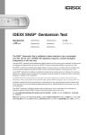
PASTEURIZATION
TIME/TEMPERATURE REQUIREMENTS
VAT
HTST
TIME TEMP
WHOLE
MILK,
LOW FAT,
SKIM
MILK
PRODUCTSwith increased
viscosity, added
sweetener, or fat
content 10% or
more
EGG NOG,
FROZEN
DESSERT
MIXES
HHST
TIME TEMP
TIME TEMP
30 MIN 145o F
15 SEC 161o F
1.0 SEC 191o F
0.5 SEC 194o F
0.1 SEC 201o F
.05 SEC 205o F
.01 SEC 212o F
30 MIN 150o F
15 SEC 166o F
SAME
25 SEC 175o F
15 SEC 180o F
SAME
o
30 MIN 155 F
Note: Those pasteurized milk products that are further heated in an acceptable system to a minimum of
280o F for a minimum of 2.0 seconds are to be labeled as "Ultra Pasteurized".
9
10
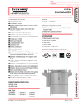
Chapter I
BACKGROUND AND HISTORY
History Department
MI L K
Cow College
11
MILK PASTEURIZATION, THEN AND NOW
Although Louis Pasteur is the one name most often
referenced in discussions the inception of what we now know as
pasteurization, actually the concern for methods to preserve
the safety of milk began long before Pasteur's first experiments
of heating wine to preserve its freshness. As early as the 1500’s
Austrian officials implicated milk in an epidemic which led to
much thought concerning safety issues of milk consumption.
However, it was not until 1824 that William Dewees recommended the
application of heat to milk as a method of preservation.
Following several illnesses in the late 1800's, thought to be typhoid
outbreaks, and after investigations into the so called “slop-dairies”, authorities
from the New York Academy of Medicine considered the definite need for some
type of preservation process to be applied to milk used by babies and the old
and infirm. This group met with little success since these “slop-dairies” were
being utilized for spent grain disposal from the large breweries in the New York
area. In these operations the milk was produced and processed in the same
grossly unsanitary facilities connected with the breweries and distilleries.
Surprisingly, before Mr. Pasteur in 1857 officially reported that the lactic
fermentation (souring and/or curdling) of milk was greatly delayed by applying
heat to milk, Gail Borden was busy applying for a patent for the condensing of
milk under vacuum in 1853. Also, Massachusetts was adopting milk control
programs (1856).
Thus, scientists around the world were theorizing that undesirable
changes in food products were attributed to the presence of microorganisms
in the food and that these “germs” could be controlled by the application of
heat.
Pasteur, along with other renowned scientists of the era, such as
Abraham Jacobi, N.J. Fjord, and Albert Fesca made significant contributions
to the equipment designs used for milk processing systems.
12
BACKGROUND AND HISTORY
Some of the early equipment was very crude; however many are simply
prototypes of the equipment we see in large modern dairies today. It is
important to note here that the concepts of continuous agitation and
processing were employed in Fjords system known then as the “Danish
Pasteurizer”.
Denmark enacted a law in 1898 requiring the heating of all calf fed milk
to 185oF to prevent the spread of bovine tuberculosis. This was indeed one of
the first forerunners of modern commercial milk pasteurization.
Nathan Stauss, a noted philanthropist, in 1893 saw the marketing
advantage of heating milk for infant feeding and later financed a “chain”
(perhaps the first real milk franchise) of what he called “milk depots” in New
York City. He utilized pre- sterilized glass bottles (dry heat method) and the
milk was heated to 167o F for 20 minutes, cooled, and sold for consumption.
Some adversaries believed that destruction of some of the organisms in
milk could allow others to produce toxins in the milk, cause undesirable flavor
problems, and destroy many nutrients. Fortunately, however, researchers
furthered Pasteur’s experimentation and proved that the use of lower
temperatures destroyed spoilage organisms and
incidentally...pathogens.
After Park and Holt had showed evidence of the
positive attributes of feeding pasteurized, vs. raw milk to
infants in tenement houses in 1903, the United States Public
Health Service began studies and confirmed the public health benefits of heat
treating (now being called pasteurization) milk.
Milk, as nature’s most perfect food, is therefore also a perfect medium
in which bacteria can thrive. Realizing this attribute, many states, Illinois
being one, began to develop laws regarding the tuberculin testing of dairy
herds, and restricting milk sales to those herds which had been tested. In 1914
New York City required by law that all milk sold must be pasteurized. In 1920
the American Public Health Association’s Committee on Milk Supply reported
13
BACKGROUND AND HISTORY
almost 4200 milk plants failed to meet even minimum milk pasteurization
standards.
Following engineering studies (known as the Endicott Experiments since
they were conducted in Endicott, N.Y.) conducted by Dr. Charles E. North of
the North Public Health Bureau and the Borden Farm Products Company, the
Public Health Service published a bulletin (no. 147) attesting that there were
indeed MAJOR improvements necessary to protect the public health and
assure a milk product free of pathogens.
Perhaps the single most contributing factor to the public health
regulatory control of milk pasteurization and safety occurred in 1924, when the
state of Alabama initiated a request for assistance from the U. S. Public Health
Service to develop a milk sanitation program.
The work between this state and the federal government eventually led
to the development of the first proposed Standard Milk Ordinance (November
7,1924--Public Health Reports). This first milk code initiated actions by other
interested states and in 1927 a uniform national Code was published which
included both technical and administrative notes for satisfactory compliance.
This was a major milestone. Now minimum pasteurization standards could be
further developed and established on a uniform nationwide basis. Little did
they realize that 25 years later the National Conference would be established
from these initial efforts.
Developments then flourished. The first plate heat exchangers were
introduced into the U.S. in around 1928. Earlier in 1927 the application of a
higher heat process was evolving in Europe. Pennsylvania in 1931 conducted
studies relative to the thermal destruction of pathogens using 160oF for a 15
second hold time.
Only slight changes were made to the pasteurization requirements in the
1930’s. The 1939 edition of the Milk Ordinance and Code, although not
requiring pasteurization, highly recommended that cities adopt the Ordinance
if permitted in their local codes.
14
BACKGROUND AND HISTORY
In 1950, the Bell studies suggested that the organism Coxiella
burnetii which is responsible for several Q-fever (Query fever)
outbreaks in Southern California could survive the then current
pasteurization requirements. This is a febrile rickettsial disease
producing flu-like symptoms
As a result, the USPHS in cooperation with University of
California-Davis recommended increasing the minimum batch
pasteurization temperature from 143o to 145o F (maintaining
the 30 minute minimum holding period). Also those milk
products with added sugar and/or fat would require an
additional 5 degrees heat.
The application of heat to milk for the purposes of preservation, with the
extra benefit of the protection of public health, continues to develop.
Innovative methods are now available for processing milk at ultra high
temperatures (UHT) with reduced holding times.
Pasteurization systems have become more complex. Methods of
concentration have evolved from the mid-1850’s G. Borden’s vacuum condenser
to the ultramodern methods of concentration. Modern systems process milk
and milk products through micro-membranes and multi-stage evaporator
calandria systems utilizing highly efficient heat recovery/ regeneration
systems. One of the latest major developments of the 1980’s in the U.S. has
been the aseptic processing and packaging or so called “sterile” milk systems
which can effectively provide six to nine months shelf life under nonrefrigerated conditions.
WHY ALL THE FUSS??
Perhaps, now that we have followed the development of pasteurization
15
BACKGROUND AND HISTORY
we must ask another question.....why?
Most of us have knowledge of at least the basics of the biological sciences
and may have advanced degrees in biological sanitary sciences. Others might
also have advanced degrees in engineering, public health, or dairy processing,
and are familiar with the inherent problems associated with milk and its ability
to support the growth of disease producing organisms.
Dr. Ben Freedman, in his benchmark reference book for sanitarians
entitled Sanitarians Handbook” proclaims that “Milk is the first food of human
life.” It is the most nutritious food known, but also the most quickly
perishable food as a result of bacterial action”. He also has written that from
the period 1938 to 1950, milk was eight times more powerful in causing illness
than were water borne diseases, and that it is through the work of milk
sanitarians and the dairy industry that milk has become one of the nations
safest and most widely consumed foods.
However, we must not "leave the chicken house unguarded." Milk does
not exit the teat end of a lactating dairy animal in sterile form. Even if
extracted in a sterile manner, milk would be likely to contain organisms from
within the cow’s udder.
Although varying in number, the average plate count of milk drawn in this
manner would vary from 10 organisms per cubic centimeter to several
thousand.
Udder diseases known as mastitis also contribute significant numbers of
bacteria, including Streptococci, Staphylococci, Tubercle bacilli, and Brucella
abortus. The environment can contribute other organisms such as Salmonella,
Escherichia coli, Aerobacter micrococcus, Lactobacillus, and the more recently
identified Listeria, Yersinia and Campylobacter.
Actually you cannot name even one pathogen that would NOT thrive readily in
milk. Therefore, we still are not out of the water completely and must
16
BACKGROUND AND HISTORY
continue to be aware of the potentials associated with handling and processing
a "potentially hazardous food."
Just recently the FDA and CDC have received reports
implicating milk products in the transmission of pathogens and
responsible for human illness.
**1982 - 172 confirmed with Yersiniosis from drinking
pasteurized milk in Little Rock, Memphis and Greenwood, MS.
Of these 172, 10% were misdiagnosed and underwent
unnecessary appendectomy operations. Investigation revealed
pig farmer collecting route returns and returning contaminated
cases back to plant. The causative was not found in the milk, however was
isolated from the swine, empty returned cases, and cultures isolated from the
victims.
**1984 - Brucellosis in humans, causative factor, illegal Mexican style cheese in
Texas.
**1985 - Salmonella outbreak in Chicago, 16,000 culture confirmed cases, 2
deaths, from consumption of pasteurized milk. Plant never reopened.
**1986 - Listeria monocytogenes causative agent responsible for 146 confirmed
cases of Listeriosis when a nurse at a large Los Angeles hospital reported
accelerated cases of miscarriages in _ Hispanics. There were 89 deaths.
Investigation that followed implicated Mexican style (soft) cheese processed at
a small plant in the L.A. area. Plant inspection revealed problems with cross
connections and post pasteurization contamination.
**1990 - Outbreak of Staph enterotoxin associated with whipped butter in a
large hotel in Reno, NV. Suspect temperature abuse at the processing plant.
Testing at the source of butter manufacturer showed negative for staph
organisms.
**1992 - E. Coli 0157 outbreak reported transmitted by ingestion of
17
BACKGROUND AND HISTORY
unpasteurized milk.
**1993 - Type A Botulism toxin caused at least one death in Georgia. Problem
associated with institutional packaged (#10 can) cheese spread in small
convenience type store.
**1994 - Salmonellosis enteritidis outbreak, THOUSANDS of cases reported from
consuming contaminated ice cream. Plant located in Midwestern state shipping
to 48 states. Firm received mix and did not re-pasteurize prior to freezing and
packaging. Follow-up shows mix was hauled in a tanker which was just prior
used to haul raw liquid eggs. Two consumer samples were
presumptive positive. Product was immediately recalled from
the market. This outbreak should send a message to the
frozen dessert industry that all mix SHALL BE PASTEURIZED in
the plant of packaging and the unnecessary handling of
pasteurized milk products must not be condoned.
**1995 - Yersiniosis enterocolitica outbreak reported in New England.
Epidemiological studies placed suspect on contamination of pasteurized milk
from operation of a small swine operation on the premises of the producerprocessing dairy responsible. There was no case washer in the plant. The
bottle washer had no sanitizer.The pigs were housed in the same barn with the
dairy animals. Five culture confirmed illnesses were confirmed in two states.
Samples of raw milk showed positive Yesinia. Environmental swabs were taken
and the organism was not found to be present in the plant environment.
**1995 - Listeria outbreak in Ohio. Suspected source was product from frozen
dessert plant. A follow-up inspection of the plant revealed several problems
with the pasteurizer problems (flow diversion valve and flow promoters not
operating properly) and direct cross connections between raw and pasteurized
lines.
**1998-Outbreak caused by E.Coli 0157:H7 (Enterohemorrhagic - Escherichia
18
BACKGROUND AND HISTORY
coli) which manifest itself by Diarrhea, often bloody, abdominal cramps.
Contaminated Cheddar and Colby cheese curd from adding raw milk to
processing vat using a common bucket. Investigation found pasteurizer cut-out
temperature at 159 degrees F, dripping condensate over cheese vat, use of
unpasteurized city water to “push” pasteurized product in lines, cross
connections between water and product throughout the plant and poor reworking practices at a receiving plant. 40 known cases of illness with 20
culture confirmed cases on record.
In FY93 alone there were twenty two official nationally documented FDA
product recalls of dairy related processed/packaged products. Some of the
problems and reasons for these recalls were:
1. Product contaminated with Listeria monocytogenes. (Three
separate cases of U.S. hard and semi-soft cheeses.)
2. Product contained undeclared food colorings.
3. Product contaminated with (unnamed) bacteria.
4. Metal fragments found in packaged product.
5. Botulism potential in product (pasteurized process cheese).
7. Powdered whole and low fat milk contaminated with
Salmonella.
8. Yogurt and shake mix contaminated with Salmonella organisms.
Noting the above, we, as public health professionals, milk industry quality
control consultants, plant management and employees, must evermore realize
and stress the significance of assuring the proper production, processing and
handling of milk and milk products.
Pasteurization is the only public health measure which, if properly
applied, will adequately protect against all infectious milk-borne
disease organisms which may have entered the milk prior to
pasteurization.
19
BACKGROUND AND HISTORY
We cannot, however, assume that the pasteurization of milk will
completely assure a safe product for the consumer. The “human factor” and
equipment failures can play an equally significant role in the safety and
wholesomeness of any food product, and even more so in milk.
This manual will concentrate efforts towards the principles, theories and
mechanics of proper pasteurization techniques. System controls will be
discussed; time-temperature- pressure relationships will be repeatedly
stressed. Methods of assuring the minimum standards will be emphasized, and
probably more importantly for this course, the acceptable and legal
requirements and recommended techniques for testing of legal pasteurizers
will be emphasized.
This course manual in subdivided into the three basic types of
pasteurization, vat, or “batch” type, high-temperature, short-time, and a short
section on steam injection pasteurization.
In HTST pasteurization, chapters are also devoted to the use of auxiliary
equipment and associated required controls. There is also a section on
magnetic flow meters, or meter based systems that will provide the participant
with the current requirements for their installation and testing.
The manual has been supplemented with various drawings, graphics,
photos, and product flow schematics for the student's reference.
As more and higher quality milk has become available, questionable and
often inferior supplies have been largely eliminated. Reliable information
about the quality of milk products is readily available and the need for costly
duplication of regulatory efforts has been largely eliminated.
The success of the National Conference of Interstate Milk Shipments has
increased confidence for the work of other food related control activities. The
milk program, which operates on the basis of promoting uniformity and
reciprocity of inspection programs, is currently serving as a model for many
food control and inspection programs.
20
BACKGROUND AND HISTORY
For example the Interstate Shellfish Sanitation Program and many of the
current HACCP (hazard analysis of critical control points) concepts were borne
from the basics and diligence of milk inspection principals, regulations and
methods of inspection.
Consumers can now be relatively assured of the safe and
wholesome quality of milk products purchased from the retail
shelves. Seldom are milk products implicated in major foodborne outbreaks. The development of methods,
procedures, equipment, and yes, regulations and
standards, over the years has resulted in an
effective method of providing the consumer one
of the safest and most wholesome foods available
in the nation today.
21
BACKGROUND AND HISTORY
COURSE OBJECTIVES
AT THE END OF THIS COURSE THE PARTICIPANTS SHOULD BE ABLE TO:
Describe the basic process methods, principles and requirements of
Batch, High Temperature Short Time (HTST), and Higher Heat, Shorter Time
(HHST) pasteurization systems.
Be able to explain the reasons for, and methods used, to evaluate and
regulate the TIME-TEMPERATURE-PRESSURE relationships in pasteurization
systems.
Be able to list the basic and auxiliary equipment components of
pasteurization systems, including vat, HTST, meter based, HHST systems and
give the PMO requirements and public health reasoning for legal installation.
Correctly perform the required tests for pasteurization systems by using the
classroom pasteurization demonstration unit and/or the HTST unit at a milk
plant during the class field trip.
To be able to correctly trace product flow through pasteurization systems,
and explain the public health controls necessary to satisfy the timetemperature-pressure requirements, including regulatory seals where required,
using the case study method.
22
BACKGROUND AND HISTORY
SIGNIFICANT EVENTS IN THE DEVELOPMENT
OF
MILK PASTEURIZATION
1765 THE ITALIAN NATURALIST, SPALLANZANI, NOTED THAT BOILING PRESERVES
MEAT EXTRACTS.
1782 THE SWEDISH CHEMIST, SCHEELE, PRESERVED VINEGAR BY BOILING
1810 APPERT USED HEAT TREATMENT TO PRESERVE FOODS (CLOSED
CONTAINER).
1861 THE "GERM THEORY" WAS DEVELOPED
1864 PASTEUR REPORTED THAT HEAT APPLICATION TO WINE AND BEER
PREVENTS ACID, BITTER AND ROPY DEFECTS IN WINE. (THIS
PROCESS WAS TERMED "PASTEURIZATION".)
1867 PASTEUR APPLIES HEAT TO MILK AND REPORTS THE PROCESS POSTPONED
MILK SOURING.
1886 THE HEATING OF MILK (BOILED IN A BOTTLE ) FOR INFANT FEEDING
REDUCED ILLNESS AND SAVED LIVES BY ELIMINATING PATHOGENS
WAS ADVOCATED BY SOXHLET (GERMANY), JACOBI (U.S.).
1893 STRAUS SET UP FACILITY TO PASTEURIZE MILK FOR INFANTS.THE FIRST
MEDICAL COMMISSION WAS FORMED TO OVERSEE THE PRODUCTION
OF “CERTIFIED MILK”.
1920's “ENDICOTT STUDIES” OCCURRED IN ENDICOTT, NY BY DR’S
NORTH
AND PACK DEVELOPING TEMPERATURE DESTRUCTION
CURVES RELATIVE
TO MYCOBACTERIUM AND TUBERCULOSIS
1924 THE USPHS CREATED "THE OFFICE OF MILK INVESTIGATIONS" UNDER THE
STRONG LEADERSHIP OF LESLIE CARL FRANK.
23
BACKGROUND AND HISTORY
1924 THE STATE OF ALABAMA WORKED CLOSELY WITH THE USPHS TO DEVELOP
THE FIRST FEDERAL MILK ORDINANCE PATTERNED AFTER "THE
ALABAMA STANDARD MILK GRADING ORDINANCE."
1941 PYREX HEAT-RESISTANT GLASS PIPING USED IN DAIRY INDUSTRY AS A
MEANS OF CONSERVING CRITICAL MATERIALS DURING WARTIME.
1952 SEVERAL STATES MET IN ST LOUIS TO DISCUSS THE PROBLEMS OF
RECIPROCITY FOR SHIPPING MILK ACROSS STATE LINES. THIS WAS
THE FIRST NATIONAL CONFERENCE ON INTERSTATE MILK
SHIPMENTS. ALSO MUCH RECOGNITION TO DR. C.A.ABELE AND DR.
EVERETT WALLENFELDT FOR THEIR EARLY PIONEERING EFFORTS IN
THE DEVELOPMENT OF THE GRADE A MILK PROGRAM.
1953 THE FIRST 3-A STANDARD FOR CIP CLEANING WAS PUBLISHED.
1955 THE FIRST AUTOMATED CIP SYSTEM INSTALLED IN AN OHIO MILK PLANT.
1956 MINIMUM TEMPERATURE FOR VAT PASTEURIZATION WAS RAISED FROM
142oF TO 145oF BASED ON HEAT RESISTANCE OF Coxiella burnetti.
BASED ON UNIVERSITY OF CALIFORNIA-DAVIS STUDIES IN LATE 1940'S
1966 FDA MEMORANDUM ACCEPTS DUAL STEM (CIP) FLOW DIVERSION DEVICE TO
BE USED IN HTST SYSTEMS.
1978 FIRST U.S. UHT “STERILE” MILK SYSTEM COMMISSIONED IN GEORGIA.
1979 MAGNETIC FLOW METER SYSTEMS FOUND ACCEPTABLE FOR USE AS
REPLACEMENT FOR CONVENTIONAL TIMING PUMPS.
1985 MAJOR SALMONELLOSIS OUTBREAK IN CHICAGO SPAWNED INCREASED
EMPHASIS ON MILK PROCESSING SANITATION. BECAME KNOWN AS
THE “DAIRY INITIATIVES”. EMPHASIS PLACED ON IN-DEPTH FDA AND
STATE RATINGS INVOLVING DOWN- TIME EQUIPMENT INSPECTIONS,
PRODUCT SAMPLING, AND TRACING PRODUCT FLOWS TO EVALUATE
POSSIBLE CROSS CONNECTIONS.
24
BACKGROUND AND HISTORY
1986 LISTERIA OUTBREAKS IN CALIFORNIA FUELS FURTHER INVESTIGATIONS ON
POST PASTEURIZATION CONTAMINATION PROBLEMS IN CHEESE AND
MILK PLANTS.
COMPUTER CONTROLS ACCEPTED FOR MILK
PASTEURIZATION SYSTEMS
1994 SALMONELLA OUTBREAK TRACED TO ICE CREAM. PROBABLE ETIOLOGY
WAS HAULING OF RAW LIQUID EGGS IN MILK TANKER WHICH WAS
USED TO SUBSEQUENTLY HAUL PASTEURIZED MIX. FREEZING AND
PACKAGING WAS DONE WITHOUT RE-PASTEURIZING THE MIX.
LARGE NUMBERS OF CULTURE CONFIRMED CASES.
1994 CONTAMINATED WATER IN A PLANT WAS SUSPECTED CAUSE OF PACKAGED
MILK TRANSMITTING E. COLI TO CONSUMERS IN MONTANA. FAILURE
OF WELL DISINFECTANT LED TO SUBSEQUENT CONTAMINATION OF
PASTEURIZED MILK STORAGE TANK. CULTURE CONFIRMED CASES.
PLANT CLOSED.
25
BACKGROUND AND HISTORY
THERMAL PROCESSING
The term “thermal process” generally refers to a process during which a
food product is subjected to high temperatures with the objective of
inactivating undesirable microorganisms or enzymes.
TYPES OF HEAT PROCESSING
1. PASTEURIZATION
a) Temperatures are generally below 212o F
b) Time of exposure varies
c) Time-temperature is lethal to pathogens in vegetative state; many
2. CANNING
a) Temperatures are above 212o F
b) Time of exposure varies
c) Lethal to spores (rod shaped), "botch
cook"
3. STERILIZATION
a) Temperatures are above 250o F
b) Time of exposure is short to minimize product damage
c) Implies "commercial sterility" where level of viable cells is a statistic.
Commercial sterility is defined as the time\temperature relationship necessary
for destruction and\or inhibition of the organisms of public health significance as well
as all significant spoilage organisms and is specific for each food type and
formulation.
Thermal process is necessitated by the fact that plant and animal tissue
and fluids are normally and naturally contaminated with microorganisms and/or
enzymes which may cause undesirable changes in the product during storage.
26
non-pathoge
BACKGROUND AND HISTORY
Pasteurization is a thermal process that kills part but not all of the
vegetative microorganisms in the food and is consequently used for foods
which are further processed or are stored under conditions which minimize
growth.
In the case of milk, pasteurization is used to kill pathogenic
microorganisms.
Since some vegetative spoilage organisms and spores may survive this
heat treatment, it is necessary to keep pasteurized milk refrigerated in order
to obtain the desired shelf life. Therefore, in addition to the destruction of
pathogens and undesirable bacteria, pasteurization also extends the useful life
of the product with minimal alteration of flavor and physical characteristics.
Milk or cream used for manufactured products such as butter, cheese,
and ice cream, are subjected to heat treatments which relates to desirable
characteristics of the end product.
Organoleptically speaking, a high temperature short time process (161o F
for 15 seconds) for fluid milk is preferred, rather than a low temperature long
time treatment (145o F for 30 minutes), since HTST usually results in less
nutrient destruction and fewer sensory changes.
For market milk, pasteurization conditions and requirements are
based on thermal destruction of Coxiella burnetii, the rickettsia organism
responsible for Q fever.
27
BACKGROUND AND HISTORY
THERMAL PROCESS DESIGN and PASTEURIZATION THEORY
Designing a thermal process to accomplish the inactivation of spores or
vegetative cells requires two pieces of information:
The rate of destruction of the microorganism or spores, and the
dependence of the rate on temperature.
The temperature history of the product.
In the canning industry the term D-value; the time in minutes at a given
temperature necessary to reduce the population of microbes or spores by
90%, is widely used.
D values may be calculated by using
Stumbo's equation as follows:
Dn =
t
log a - log b
Where,
D = Time in seconds at a given temperature for a 90% reduction in
bacteria in whole milk,
n
= process temperature
t = equivalent holding time at a process temperature,
log a = the initial bacterial population per m/l
log b = the survivor concentration per m/l
28
BACKGROUND AND HISTORY
By plotting different D values on semi-log paper a straight line curve may
be obtained. The slope of this line in the "Z" value of an organism. This value
relates directly to the temperature increase that effects a ten-fold reduction in
holding time while maintaining the same lethality of the process. For example
the figure below using D120o F = 8 minutes, a reduction of from 10,000/ml to
0.0001/ml (1/10,000 ml) is equivalent to 8 log reduction or 99.999999%
reduction of organisms.
Studies on the heat resistance of pathogens were used in arriving at the D
Value necessary to assure safe and acceptable levels in the pasteurized
product.
Escherichia coli, as an example which is one of the more heat resistant of
the coliform organisms was isolated after thermal process of 76.7o C (169.8o F)
with an initial concentration of 2 X 10⁶ /ml and the survivor rate was <10-3 /ml
(1/1,000 ml). From these values a D Value of 0.246 can be established for the
Escherichia coli organism.
In the early 1920’s
when Ball and others were establishing procedures for calculating thermal
processes, the observation was made that the logarithm of the D-value was
linearly related to temperature.
The figure relating log D to temperature is call the thermal death curve.
This is an extremely significant observation in the development of thermal
process calculations, because the thermal death time curve or the equation
which describes it provides a means for equating various time/temperature
treatments in terms of thermal destruction of microorganisms or spores.
Knowing this and the temperature history of the product, the thermal
process which will inactivate a given load of vegetative organisms and spores
can be established.
According to the logarithmic order of bacteria by exposure to lethal heat,
it follows that it is not possible to completely inactivate a given population of
an organism in a milk sample of infinite size as in encountered with continuous
flow milk pasteurization. Therefore to obtain process standards an arbitrary D
29
BACKGROUND AND HISTORY
value must be established for achieving unit lethality.
PASTEURIZATION
What is it?
The application of a heat process to good quality
milk for the purpose of rendering it a safe and nutritious
food product which will survive on the shelf for a ten to
20 day period under refrigerated conditions has been the
industry standard for over 5 decades. Pathogens are
destroyed, industry and the consumer are happy and
healthy and the nation's milk supply is safe and
wholesome.
Pasteurization has been described as the principal safeguard between a
potentially dangerous milk supply and the consumer. Methods must be
dependable and equipment constructed of material and of a type that permits
easy and effective cleaning. Adequate precautions must be taken to detect and
avert faulty operational procedures.
Let’s now legally define the process of pasteurization!
PASTEURIZATION - The process of heating EVERY PARTICLE of
milk and milk products to the minimum required TEMPERATURE
(for that specific milk or milk product), and holding it continuously for the
minimum required TIME in equipment that is PROPERLY DESIGNED and
OPERATED.
Pasteurization has also been described as a heat treatment or thermal
process used to kill part but not all of the vegetative microorganisms present in
the food.
This is important to remember since the D-value was established on a 90%
microbe deactivation. This is why milk spoils under refrigeration. Biology
30
BACKGROUND AND HISTORY
informs us that certain bacteria are “heat resistant” (thermophiles) while
others are cold resistant (psychrophiles) and may withstand the heat process of
pasteurization. Certain of these non-mesophilic organisms may be introduced
into the product after pasteurization, and some may survive the pasteurization
process. No pathogens have been demonstrated to survive pasteurization in
properly designed, installed and operated equipment.
Generally, we can say that pasteurization involves a time/temperature
exposure sufficient to destroy or slow down the growth of spoilage
microorganisms, inhibit enzyme activity, kill any disease producing bacteria,
and yet retain the desired properties of the product.
Fast flowing liquids, such as wine, fruit juices, milk, etc lend themselves
to efficient handling in standard pasteurizing equipment.
CHAPTER REVIEW
1. ALL PASTEURIZERS MUST MEET THESE THREE REQUIREMENTS:
1. T:___________________________
2. T:___________________________
3. P:___________________________
2. PASTEURIZATION
DEFINITION:________________________________________________________________
___________________________________________________________________________
___________________________________________________________________________
___________________________________________________________________________
__________________________.
D-VALUE
DEFINITION:________________________________________________________________
___________________________________________________________________________
____________.
31
BACKGROUND AND HISTORY
3. Fill in the blanks:
1. Pasteurization temperatures are usually ______F___ which destroys ___________
2. Canning processes are at temperatures above__________and aimed at
__________destruction.
3. Sterilization temperatures are above _________ which render
all___________a statistical entity. It is specific for ______________
and __________________.
4. The last revision of pasteurization temperatures was in the 1940's and based
on the destruction of the organism___________________, which is responsible
for the disease__________________.
5. Three general types of bacteria thrive at different temperature ranges.
They may be classified as:
a) ___________________.
b) ___________________.
c) ___________________.
6. Most pathogens are found in the a( ), b( ), or c( ) grouping.
32
BACKGROUND AND HISTORY
33
BACKGROUND AND HISTORY
34
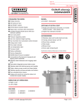
VAT PASTEURIZATION
Chapter II
35
VAT PASTEURIZATION
VAT PASTEURIZATION
PURPOSE: To understand the basic principles, and public health reasons for
the requirements of proper design and operation of a batch type or vat
pasteurizer.
OBJECTIVES:
.
To understand and be able to list and explain the compliance and
construction requirements of a vat pasteurizer.
.
To list the correct operational methods of a vat pasteurizer.
.
To be able to describe and perform all required regulatory tests for
a vat pasteurizer.
.
Know and be able to list the CRITICAL CONTROL POINTS of a vat
pasteurizer.
GENERAL DISCUSSION
The heating of milk in a vessel has long been one of the most effective
methods of rendering a relatively organism free and hopefully pathogen free
milk product.
The product is heated in a jacketed stainless steel vat which has been
fitted with water and steam to the jacket liner, thermometers to monitor and
record product temperatures, and some means of agitation to assure uniformity
in temperature distribution. Other requirements include properly designed
valves, time/temperature requirements, and methods of operation which will
be discussed in this chapter.
36
VAT PASTEURIZATION
Generally, we can say that all vat or batch type pasteurizers should
conform to "The 3-A Sanitary Standards for Non-Coil Type Batch Pasteurizers
for Milk and Milk Products", Number 24-01. This standard provides guidelines
for the installation, approved materials, finish, and fabrication of vat
pasteurizers. Also all vat pasteurizers must comply with Item 16p(A) of the
PMO, including all operational and construction requirements.
37
VAT PASTEURIZATION
VAT PASTEURIZATION-CRITICAL CONTROL POINTS
TIME AND TEMPERATURE REQUIREMENTS MET
NO TEMPERATURE ABUSE
COVERS IN PLACE DURING OPERATION
VAT CONSTRUCTION WITHIN COMPLIANCE
AGITATION DURING OPERATION
NO INGREDIENTS ADDED AFTER PASTEURIZATION
PRODUCT PROTECTED AFTER PASTEURIZATION
38
VAT PASTEURIZATION
Figure 1
Schematic of a Vat Pasteurizer
39
VAT PASTEURIZATION
BATCH PASTEURIZER CONSTRUCTION
STANDARDS
1. Valves - Outlet valves must comply with the close coupling
standards established by the 3-A Standards.
a. The valves must be constructed of solid stainless steel to permit
adequate heat transfer to the inner portions of the valve and so designed
as to prevent the accumulation of unpasteurized milk in the milk passages
of the valve when the valve is in a closed position.
b. All outlet valves must be of the leak protector type, which are
designed to prevent leakage of raw milk past the valve body. The leak
detector groove must be at least 3/16 inch in width and 3/32 minimum
depth at the center to prevent clogging. (Note - presently there are no
air operated valves acceptable for use as vat pasteurizer outlet valves).
A limited number of cone bottom tank protector type valves were
fabricated; however their current availability is extremely limited. These
valves are designed with spiral shaped grooves designed which expel any
leakages past the valve seat to the floor. If cone bottom vats are utilized
as vat pasteurizers special consideration should be given to proper
product agitation capabilities and other construction requirements of
these type vats.
c. All vat pasteurizer outlet valves must be fitted with stops which
provide the operator with a physical indication of complete valve closure
during the entire filling, heating, and pasteurization holding period
operation.
d. Outlet valves must be of the close coupled design; that is, designed so
as to prevent the accumulation of unpasteurized milk in the milk passage
of the valve when in the closed position.
40
VAT PASTEURIZATION
e. All vats used for pasteurization must be fitted with adequate means of
continuous mechanical agitation.
f. The requirements outlined in Ma-76 prohibits the practice of leaving
the raw milk fill line to remain in place in the vat pasteurizer during the
holding time phase since complete separation between raw and
pasteurized milk product is required at all times.
g. Outlet valves which are mounted vertically, as on cone bottom vats,
must have a leak detector groove arrangement which will allow free
drainage of any product past the plug while in the closed position.
Grooves must be curved or placed at such an angle to accomplish proper
draining. Diagrams of these valves may be found in the 3-A Standard 0817, Part 2, drawings 100-28 and 100-29.
41
VAT PASTEURIZATION
Figure 2
Figure 3
Close Coupled Outlet Valves
42
VAT PASTEURIZATION
2. Covers
a. All openings must be provided with covers constructed to prevent the
entrance of surface contamination or foreign material. The main cover
or lid shall be designed to remain in the open position (to facilitate
processing and/or cleaning), and shall be sufficiently rigid and self
draining. The main lid shall be designed so that raising will not allow any
liquid or other contamination to enter the pasteurizer.
b. Openings in the tank or vat cover must be equipped with raised edges
to prevent surface drainage into the milk.
c. The vat cover and any opening into the tank interior must have
overlapping or "shoe box" type edges. The covers must be relatively
close fitting and overlap the opening.
d. All pipe, thermometer, agitator shafts, or other appurtenances that
extend down into the vat must do so only through condensation
diverting aprons unless a water tight joint is used.
3. Agitators
a. All vats used for pasteurization must be equipped with a mechanical
means of assuring that each and every particle of milk is heated. This is
accomplished by mechanical/electrical motor driven agitators. The
most efficient agitators will be designed to push the product down and
sweep the product across the heat exchange surface on the sides and
bottom of the vat. Agitators shall be designed to result in uniform
product and temperature throughout the vat. Product temperatures
variances must not exceed 1oF between any two points within the vat at
any time during the holding period.
b. Agitators must meet construction criteria for milk contact surfaces
and be designed to be easily cleanable and/or removable for manual
cleaning.
43
VAT PASTEURIZATION
c. Agitator shafts must be fitted with effective drip deflection shields to
prevent contamination of the milk.
d. Agitator shaft openings shall have a minimum diameter of one inch to
allow for removal and cleaning of the agitator shaft.
e. The annular space around the agitator shaft shall be fitted
with an umbrella or drip shield of sanitary design to protect
against the entrance of contaminants.
4. Indicating and Recording Thermometers
a. Indicating thermometers shall be of the mercury actuated, directreading type, scaled to a minimum of 0.625 of an inch, with a span of
not less than 25 degrees F which includes the pasteurization
temperature (plus or minus 5o F) and graduated in
1o F, and accurate to within 0.5o F. Provided that electronic RTD
direct reading type thermometers that meet the requirements and
are acceptable to FDA may be used as indicating thermometers on batch
type pasteurizers.
b. The sensing bulb of the indicating thermometer (official
thermometer) must be designed to extend fully into the product
during pasteurization.
c. Each vat pasteurizer must be provided with an approved air space
thermometer. The air space thermometer must meet the same general
requirements of the indicating thermometer with exception of the bulb
length, degree increments, and accuracy requirements.
44
VAT PASTEURIZATION
Figure 4 – Indicating Thermometer
The bottom of the bulb chamber for air space
thermometers must not be less than 2 inches nor
more than 3.5 inches below the underside of the top
enclosure, bridge, or cover. The bottom of the bulb must never be less than 1
inch from the top surface of the product during pasteurization. The air space
thermometer may be graduated in 2 degree maximum increments and must be
accurate to plus or minus 1 degree F.
45
VAT PASTEURIZATION
d. Each vat must also be equipped with a recording thermometer. This
thermometer must be graduated in 1o F increments between 140o F and
155o F.
The chart must be graduated in time scale divisions of not more than 10
minutes for a maximum record of 12 hours and must be specifically
designed (and so identified) for the type of recorder being used.
e. On those vats used solely for pasteurizing at temperatures greater
than 160o F, the recording chart may be graduated in 1o C (2o F). The 1o C
(2o F) increments shall be in the 150o to 170o F range. On these type
vats, the chart may be graduated in 15 minutes for a maximum of 24
hours.
The recorder device may be either electric or spring driven.
Required recorder chart information (for each product batch):
1) Name of milk plant.
2) Date.
3) Signature or initials of the operator.
4) Identification of the recorder when more than one vat is
5) Record of holding time including empty and fill times as
6) Reading of air space thermometer at the beginning of the
7) Reading of indicating thermometer at an indicated point
8) Amount and name of product represented by each batch.
9) Record of any unusual occurrences.
Charts shall be retained for 3 months.
46
VAT PASTEURIZATION
47
VAT PASTEURIZATION
5. Air space heaters may be necessary to maintain minimum air space
temperatures. These devices must be of sanitary design, meet all 3-A
Sanitary requirements, including installation and culinary steam
requirements. The air space heater must be easily demountable for
cleaning (See Appendix H of the PMO, for culinary steam requirements or
Figure 5 below.)
Figure 5
Air Space Heating
48
VAT PASTEURIZATION
BATCH PASTEURIZER OPERATING STANDARDS
1. All product components must be added to the batch prior to
beginning the pasteurization process. This includes any liquid sugar and
sweeteners, water, milk powders and all other dairy products, flavorings,
stabilizers, cocoa products, emulsifiers, and vitamins.
There are certain flavoring ingredients that may be added after
pasteurization. These include flavoring ingredients having an aw of 0.85
or less, high acid content, dry sugars, fruits and roasted nuts, safe and
suitable bacterial culture organisms, and flavorings containing a high
alcohol content. Fruits and vegetables may be added to cultured products
having a pH of 4.7 or less.
Such ingredients addition shall be done in a sanitary manner and the
ingredients must be of a safe and wholesome quality.
2. Pasteurization must be performed in equipment which is properly
designed and operated, and which insures that every particle of product
will be held continuously for the minimum time and temperature. Vats
should be designed so that product can be heated to pasteurization
temperatures in as short a time as practicable. In no case should this
time exceed 4 hours. Following pasteurization the product must be
cooled to <45o F as soon as possible. The only exception for this cooling
requirement is for cultured products processing.
3. If for any reason the vat lid or any cover is lifted or mechanical failure
of any kind (agitator malfunction, loss of temperature below the required
minimum, etc) occurs after beginning of the pasteurization cycle, the
timing process must be restarted and notes to that effect must be
made on the recording chart by the operator.
49
VAT PASTEURIZATION
4. The official thermometer is the indicating thermometer and the
recording thermometer functions to only provide a record of the
pasteurization cycle. For each product batch the operator is required to
verify the accuracy of the recording thermometer using the indicating
thermometer as the standard. This comparison is noted on the recording
thermometer chart. No batch of milk shall be pasteurized unless the
sensors of both thermometers are covered.
5. The air space thermometer reading must also be recorded on the
recording chart during pasteurization. To assure that the minimum air
space temperatures are being maintained, the air space indicating
thermometer shall be read and recorded at the beginning of the holding
period. It is also strongly recommended that the air space temperatures
be noted and recorded during and at the end of the holding period.
During pasteurization, the air space temperature must never be less than
5oF above the minimum legal pasteurization temperature required for the
milk product contained in the vat.
6. Recording charts must be used only for the length of time for which it
has been designed. Overlapping of information on circular charts is
never acceptable and is a violation of the PMO. Required information
on the recording chart must be legible and meet all the requirements
as spelled out in the PMO.
7. The outlet valve is designed to detect and expel any leakage past the
valve seat and is close coupled to prevent cold pockets of milk from
accumulating in the valve or piping.
8. At no time during the pasteurization cycle or following
pasteurization may the outlet piping be directly attached to any line
or vessel containing raw milk or any other contaminating substance.
50
VAT PASTEURIZATION
ASSURANCE OF HOLDING PERIODS
1. Vats must be operated so that every particle of milk is held for
at least 30 minutes at or above the minimum required
temperature for the specific product processed.
2. When the milk product is heated to pasteurization temperature
in the vat and is partially cooled in the vat before opening the
outlet valve, the recorder chart must show at least 30 minutes at
or above the minimum pasteurization temperature.
3. When the milk product is preheated to pasteurization
temperature prior to entering the vat, the recorder chart must
show a holding time of 30 minutes plus the filling time of the vat
from the level of the recorder bulb sensor to the maximum level
of normal operation (pasteurization).
4. When cooling is begun after the outlet valve is opened or is
done entirely outside the vat, the chart must show a holding time
of 30 minutes plus the time necessary to empty the vat to the
level of the recording thermometer bulb.
5. These filling and/or emptying times must be indicated on the
chart by the operator by inscribing the start and end of the
official 30 minute holding time.
6. Upon close inspection, vat pasteurization recording charts used
that have been used must show clearly the four identifying holes
(marks) which verify the chart has not been rotated or manually
turned to give a false time line accuracy.
51
VAT PASTEURIZATION
52
VAT PASTEURIZATION
CHAPTER REVIEW
1. The requirements for vat pasteurization may be found in Section ___, Item ______ on
pages ____________ of the current edition of the ________________.
2. Another good reference for vat pasteurizers may be found
in:_____________________________________________________________________.
3. Currently vat pasteurizers found in many modern processing plants are used for
products such as________________________________________________________
_______________________________________________________________________.
4. Batch Pasteurization Time Temperature Standards:
Product
Temperature
Whole Milk
___________
______
Skim Milk
___________
______
Half and Half
Eggnog
___________
___________
Frozen Dessert Mix ___________
Time
______
______
______
5. The PMO requires that if the fat content of the milk product is______percent or more,
or if it contains added sweeteners or solids, the specified minimum temperature shall be
increased by ______degrees F.
6. The FDA Dairy, Inc, vat pasteurizes their cheese milk at 173o F. The operator Mr.
I.M. Messed Up must always check to make sure that the air space temperature reads at
least _______o F during the entire holding time.
7. What is the purpose of VALVE close coupling?
8. You are the night manager of a large milk processing plant. The vat pasteurizer
53
VAT PASTEURIZATION
operator notifies of the following:
CONDITION
YOUR SOLUTION
a) He forgot to add dry sugar to the mix prior
to pasteurization, however did add the sugar
at only five minutes into the beginning of the
30 minute time and then added 25 minutes to
the time after adding the sugar. The mix was
packaged last night and is ready for shipment.
b) The air space thermometer was damaged and the mercury
slightly separated, however since the milk was pasteurized
at 170 degrees he had decided to package the product
and was delivered this morning to the store.
c) The boiler lost steam pressure during pasteurization ,
but since the temperature never got below 145, the
cream was packaged and in the plant cooler anyway.
d) Pasteurized skim was put in a processing vat, super
heated, culture was added, and then pumped to the
vats for cottage cheese processing.
e) The operator discovered that they had used the last vat
recorder chart the previous day.
HTST charts were used on the vat recorder, since
the charts included the normal pasteurization
temperature range used by the plant of 160
degrees F.
9. Are any regulatory seals required on a vat pasteurizer? Y____N____. Explain.
10. Provide the following vat pasteurizer thermometer criteria:
SPAN
o
F grads
ACCURACY
Chart speed
Indicating
______o F
_____o F
_____o F
NA
Recording
______o F
_____o F
_____o F
1 rev/____hrs*
Air Space
______o F
_____o F
_____o F
For Pasteurizers using temperatures greater than 160o F-see PMO, pages 217-220.
Indicating
______o F
_____o F
_____o F
NA
Recording
______o F
_____o F
_____o F
1 rev/____hrs*
Air Space
______o F
_____o F
_____o F
NA
*Except that strip charts may show a continuous recording over a ___hour period.
54
VAT PASTEURIZATION
10. List the four significant requirements for a vat pasteurizer outlet valve.
a)
b)
c)
d)
11. Explain the reasoning for the requirement that when pre-heated product is brought into a vat
for pasteurizing, the filling time must be adjusted. How is this added time measured?
Notes:
55
VAT PASTEURIZATION
56
Basic HTST Pasteurization
57
*********************************
Note: The use of trade names or equipment photographs is for training and
educational purposes only and does not constitute endorsement by the U.S.
Department of Heath and Human Services, Public Health Service, Food and Drug
Administration.
******************************************
58
Basic HTST Pasteurization
HTST PASTEURIZATION
BASIC DESIGN, FUNCTION, AND OPERATION
PURPOSE:
To understand the principles and public health reasons for the
HTST process. This section reviews the basic design, function and
operation of the HTST system as relative to product flows and how
it influences the time-temperature-pressure relationships within
the system.
OBJECTIVES:
Following the completion of this instructional unit, the
participant should be able to:
Follow the basic flow sequence in an HTST system and give
the critical control point connected with each major component.
_ List and understand the function and installation of the basic
components of an HTST system and how they interrelate to the
time-temperature-pressure requirements.
Give the public health reasoning for each of the
requirements relative to the time-temperature-pressure concerns.
59
HTST - CRITICAL CONTROL POINTS
INDICATING THERMOMETER
ACCURACY
SCALE
RECORDER CONTROLLER
ACCURACY
DIVERSION SET POINT SEAL
SENSOR LOCATION
FUNCTION/OPERATION
CHART IN COMPLIANCE
TIMING/METERING PUMP
LOCATION
SEAL IN PLACE
HOLDING TUBE
PROPER SLOPE
UNCHANGEABLE
FLOW DIVERSION DEVICE
ASSEMBLY
FUNCTION
TIME DELAYS
DIVERT/LEAK-DETECT LINE SLOPE
BREAK AT BALANCE TANK
VACUUM BREAKER
PROPER LOCATION
60
Basic HTST Pasteurization
HTST PASTEURIZATION
I. INTRODUCTION
a. Definition
High temperature short time or HTST pasteurization is the process
of heating every particle of milk product in properly designed and
operated equipment to the minimum temperature requirement and
held continuously at or above that temperature for at least the
minimum time required.
For example: Whole milk must be held at 161o F for 15 seconds, while milk with higher milk fat content
and/or added sweeteners shall be heated to at
166o F and held for at least 15 seconds.
b. HTST BASIC DESIGN AND FLOW PRINCIPLES (Figure 9)
1. COLD RAW MILK enters the constant level tank (approximately
40 degrees) and is drawn under reduced pressure into the
regenerator section of the press.
2. In the regenerator section, the cold raw milk is pre-warmed
by the heat given up by the hot pasteurized milk flowing in a
counter current direction on the opposite side of the milk to milk
regenerator plates.
3. The raw milk, still under suction, is drawn through a positive
displacement timing pump which delivers it under positive
pressure through the remainder of the HTST system.
4. Under positive pressure the raw milk is pumped through the
heater section where steam heated hot water on opposite sides of
the stainless steel plates continues to heat the milk to a
temperature exceeding the minimum pasteurization temperature.
5. The hot milk, now at or above legal pasteurization
temperature, and under pressure, flows through the holding tube
61
where the transit time ("hold") is at least 15 seconds. The velocity
or rate of flow of the milk through the holding tube is totally
governed by the speed of the timing (metering) pump. We could
say then that the residence time of the milk in the holding tube is
determined by the pumping rate of the timing pump, the length
of holding tube, and the surface friction of the milk product.
6. The milk then contacts the sensing bulbs of the indicating
thermometer and the recorder controller. If the milk
temperature is not at or above the minimum required set point,
then the sub-legal milk is returned back to the constant level
tank via the diversion port and line of the flow diversion device.
7. If the milk contacts the STLR at or above the minimum set
point (161oF), the recorder controller signals the flow diversion
device to assume the forward flow position and the milk flows
through the forward flow port of the flow diversion device. The
milk from this point continues its flow through the system as
legally pasteurized product.
8. The hot pasteurized milk then passes through the milk to milk
regenerator (on the pasteurized side of the plates) and gives up
heat to the cold raw product on the opposite side of the plate. In
turn, the pasteurized milk is partially cooled.
9. The partially cooled pasteurized milk then passes through the
cooling section, whereby re-circulated coolant water (sweet water
or propylene glycol) is used to reduce the milk temperature to
below 45oF.
10. The cold pasteurized milk then exits the cooler section and
rises to an elevation of at least 12 inches above any raw milk in
the HTST system and is opened to the atmosphere through a
sanitary vacuum breaker at that point (or higher).
11. From this point, the pasteurized milk may travel directly to a
storage or surge tank for subsequent packaging or may be returned
back to the constant level tank.
62
Basic HTST Pasteurization
63
II. COMPONENTS OF THE BASIC HTST SYSTEM
A. CONSTANT LEVEL SUPPLY TANK (Balance Tank)
1. Sanitary Design
The balance tank must be of a sanitary design, meet all
criteria of the PMO, 3-A
Standards, and the design
dimensions of MI-87-3.
2. Functions
a. Provides a continuous
supply of milk to the HTST
unit.
b. Provides return storage for sub-legal milk from the flow
diversion valve.
c. Provides a means for the recirculation of pasteurized milk.
d. Provides a reservoir for CIP/ cleaning purposes.
3. Controls
a. The overflow level of the balance tank must be installed
(recommended at least one inch) below the lowest level of
raw milk in the regenerator.
64
Basic HTST Pasteurization
b. Raw milk generally must enter the regenerator section at
the bottom of the press. If the system is equipped with a
start-up regenerator by-pass line with a non-restricting
intervening valve, then the raw milk line may enter at the
top of the "press".
Figures 8
Acceptable Balance Tank
Designs
65
66
Basic HTST Pasteurization
B. THERMAL EXCHANGE SYSTEMS
1. Plate Heat Exchangers
a. Sanitary design and construction
b. General sections are:
1). heating
2). cooling
3). regeneration
c. Flow patterns
d. Proper maintenance
and inspection
e. Controls
Figure 9
Plate Heat Exchanger Frame Press
67
Figure 10, Plate Heat Exchanger - Flow Patterns
68
Basic HTST Pasteurization
2. Tubular Heat Exchangers
a. Sanitary design and construction. The interior of these “pipe-in-a
pipe” regenerators must be smooth and cleanable and have access points
for inspection.
b. Flow patterns. Raw and pasteurized milk flow in opposite directions
which enhances heat exchange.
c. Controls. Milk-milk tubular heat exchangers must meet all
requirements of plate heat exchangers, i.e., pressure controls (if
applicable) and in all cases vacuum breaker installation (in HTST
systems).
Figure 11
Tubular Heat Exchangers-Flows
69
C. TIMING (METERING) PUMP
1. Location
In basic HTST systems, the conventional timing pump will be the only
flow promoting device in the system. Timing pumps, when used in
systems with milk-to-milk regenerators, must always be placed
downstream from the raw regenerator. This is to assure that during
operation raw milk pressures in the milk to milk regenerator are
relatively less than pressures on the pasteurized side of the plates.
Timing pumps may be speed adjustable but are always set and sealed at
the fastest minimum legal pasteurization time(s). Some timing pumps
are electronically controlled and this controller must also be under
regulatory seal. Timing pumps may operate at any time except when the
dual stem flow diversion device mode switch is in the “Inspect" position
or during diverted flow, the flow diversion device is improperly
assembled and the micro switch is not in the proper position.
2. Types
a. Positive displacement type - Positive pumps may be of
several types, two of which are in common usage in the
continuous flow pasteurizer.
One is the gear driven type pump where two rotors or
impellers revolve within an oval case. Close tolerances
between the gears and the outer case make the space or
pockets between the teeth or lobes carry the fluid around
the periphery of the pump body. The size of these
pockets and the speed at which they revolve determine
the volume that will be pumped. It is important to remember that the
efficiency of these impeller type pumps may be
greatly influenced by the temperature and type of
liquid they are pumping. This becomes important
when performing the holding time water: milk tests
and calculations for systems with these type (PD)
pumps.
70
Basic HTST Pasteurization
During operation, the gears are lubricated by the fat in the product.
The impellers must be disassembled at the end of each operating period and
manually cleaned and should be lubricated with a sanitary lubricant when
reassembling.
Figure 12
Positive Displacement Rotary Pump Function
b. Another type pump frequently used is the
belt/pulley driven piston type pump such as
the homogenizer. Homogenizers are very
efficient positive displacement pumps and are
frequently used as the timing pump in
continuous pasteurizers.
71
c. The other type of acceptable timing pump is magnetic flow meter
based system which uses a centrifugal pump in conjunction with product flow
controlling methods. These systems will be discussed in Chapter V Meter Based
Systems.
3. Controls
a. The timing pump must be sealed by the regulatory authority at the
maximum speed to assure that the minimum holding time requirements
are satisfied.
b. It must also be inter-wired with the flow diversion device and
recorder/controller. This is to prevent the sub-legal flow of milk into the
pasteurized side of the system.
c. Generally there is only one primary timing device in system. When
both a positive displacement pump and homogenizer are used as timing
pumps, both must be timed separately and together to assure minimum
holding times are achieved.
D. HOLDING TUBE
1. It must be of sanitary design.
2. It must be installed on permanent supports to assure alignment and proper
slope and pipe size changes shall be properly designed and installed...
3. The entire length of the holding tube must be properly slope to preclude air
entrapment and assure uniform product flow. The minimum upward slope is
0.25 inch per running foot, or 2.1 centimeters per meter.
4. It must be fabricated to eliminate short circuiting. (no alterable sections)
5. The holding tube starts at the salt injection port or fitting and ends at the
flow diversion device.
72
Basic HTST Pasteurization
Figure 13
Holding Tube Installation
6. Holding tubes must be designed to assure temperature variation not to
exceed 1o F.
7. Heat shall not be applied to the holding tube at any point and the holding
tube shall not be fitted with insulation materials. The purpose of this is to
allow for inspection of the tube for proper slope and to detect any
unauthorized changes in length.
73
E. INDICATING THERMOMETER –
1. Purpose
To indicate the accurate temperature of the product.
2. Location
At the end of the holding tube and as close as practical to the recording
thermometer sensor.
3. Specifications
a. Type -mercury actuated, direct reading, corrosion resistant case.
b. Scale - Span not less than 25o F including pasteurization temperature
plus or minus 5o F, graduated in 0.5o F divisions.
c. Accuracy - 0.5 degrees F, plus or minus throughout
scale.
d. Thermometric response - 4 seconds to travel 63%
(12 degrees which includes the pasteurization range)
of a 19 degree span.
Eubanks’
Elec Indicator
e. Type - electronic
On November 27, 1991 the FDA's Milk Safety Branch
161.5
through M-b-314 allowed the use of the digital
reference thermometer (DRT) as a replacement for the mercury actuated
(MIG) indicating thermometer for use in pasteurization systems.
74
Basic HTST Pasteurization
The Anderson and Taylor Companies offer the digital reference type
thermometer, analogue type which uses a dual wound sensor on the 1000
ohm RTD (sensor device).
Differences in resistance resulting from temperature changes are
converted directly to a temperature value which is displayed on the
panel.
Fail safe operation of the DRTs is accomplished by using two separate
resistance temperature devices (RTD’s). If the two RTD's read more than
0.5 degrees F difference, the display blanks out making it impossible for
the operator to observe the temperature.
Testing of the DRT is identical to conventional tests as described in Test 1
and 7 of Appendix I of the PMO, and some additional guidelines may be
helpful in the DRT instruction manual for performing these tests.
Because of the self-diagnostic circuitry, the thermometric response test
is required as with mercury actuated type thermometers.
M-I-93-1, issued April 18, 1993 provides specific criteria for
evaluation of the new digital thermometers.
These criteria are:
1. No more than 0.5o F (0.25o C) drift over 3 months use on an HTST
system compared to a certified thermometer.
2. Readout is displayed in units of temperature with at least count of
0.1o F.
3. Display changes at a rate that can be noted by the operator or public
health authority during the thermometric lag test (Test 7, Grade A PMO).
75
4. Self-diagnostic circuitry which provides constant monitoring of all,
input and conditioning circuits. The diagnostic circuitry should be capable of
detecting "open" circuits, "short" circuits, poor connections and faulty
components. Upon detection of failure of any component, the device shall
blank or become unreadable.
5. The effect of electrical noise shall be documented and available to
public health authorities. Protocols for these tests shall be developed by
vendors with FDA concurrence.
6. The effect of high temperature and/or humidity shall be documented.
The device should show no effect after exposure to 100o F and 80%
relative humidity for 7 days.
7. Both probe and display case shall be constructed so that they may be
sealed by a health authority.
8. Calibration of the device shall be protected against unauthorized
changes.
9. The device shall be protected against unauthorized component or
sensing element replacement. Replacement of any component or sensing
element shall be regarded as a replacement of the indicating
thermometer and subject to health authority inspection and all
applicable PMO tests.
10. The sensing element shall be encased in appropriate material
constructed so that final assemble meets PMO Item 11p, Construction.
76
Basic HTST Pasteurization
F. RECORDER CONTROLLER (STLR)
1. Purposes
To automatically record pasteurization temperatures and times, a record
of the position of the glow diversion device and to automatically control
the position of the flow diversion device.
2. Location
The temperature sensor of the recorder controller shall be located
within 18 inches of, and up stream from the flow diversion device.
3. Design and Operation
The recorder controller or STLR is an electronic instrument actuated by
either a Bourdon coil attached to an ether derivative (water and glycerin)
filled capillary which responds to temperature change or may be one of
the newer type electronic programmable recorder controllers which
utilize electronic remote temperature sensing devices and/or computer
logic.
The illustration of the following page shows the mechanical works of the older
type Taylor 352R STLR. Behind the cut-a -way is found the Bourdon Coils, the
linkages of the temperature recording and event pens arms, the capsular
chamber and diversion setting and controlling mechanism, and the micro
switches. The cabinet half on the right is the hot water controller or “set” and
contains no controls of public health significance, hopefully.
.
77
78
Basic HTST Pasteurization
VAPOR THERMAL SYSTEMS
This type utilizes two Bourdon coils, one coil activates the recording pen arm;
the second coil actuates the contact assembly to initiate forward or diverted
flow. Both single and dual diversion controllers are available
79
The Taylor 351R STLR showing wiring, pneumatic controls and micro-switches. Note
the split capillarys, capsular chamber and diversion set screw
As the temperature increases, the Bourdon spring tends to unwind. This
moves the zero screw until the baffle contacts the nozzle. The baffle
thus stops the air flow through the nozzle increasing the back pressure
and supplying pressure in the capsular chamber. The action of the push
rod of the capsular chamber places the micro switch in the normally
open ( NO) position which the flow diversion device solenoid which allows
air at approximately 40 psi to compress down on the diaphragm and
spring, moving the flow diversion device to the forward flow position.
Therefore, in FORWARD FLOW, the timing pump is solely energized
through the recorder controller micro switch.
80
Basic HTST Pasteurization
Conversely, as the temperature decreases to below the diversion set
point (cut-out), this allows the Bourdon coil to retract and air to escape
through the nozzle, releasing the air from the capsular chamber, allowing the
push rod to move to the left which allows the micro switch to assume the
normally closed (NC) position. This action de-energizes the flow diversion
device air solenoid, preventing air from depressing the diaphragm and spring in
the FDD, assuring DIVERTED FLOW.
Because of the design of the recorder-controller i.e. pneumatically driven
to the right (cut-in) and spring driven to the left (cut-out), and the delay
necessary for the capsular chamber to “depressurize”, the "cut-in" temperature
will normally be slightly higher than the "cut-out" temperature on
mechanical/capillary driven recorder-controllers. This differential temperature
may be adjusted to suit operator and plant standards, but both cut-in and cutout MUST be higher than the required minimum pasteurization
temperatures. Electronic STLR’s diversion differentials are pre-set at the
factory and are usually 1-1½ degrees difference.
This recorder-controller requires a separate hot water temperature
controller to automatically control the temperature of the steam heated water
used in the heating section of the press. The hot water controller
automatically controls the steam valve which increases or decreases the
amount of steam allowed into the heating medium, depending on operator
setting.
81
Illustrated below is the basic design/function of a recorder-controller.
Figure 15-Taylor STLR
82
Basic HTST Pasteurization
The Partlow Recorder Controller
This recorder-controller
combines both the flow diversion
device recorder-controller and
the hot water temperature
controller. The right side
mechanism which uses a liquid
filled sensing bulb to activate a
plunger/mechanical switching
system to control the recorder
pen and the flow diversion
device. The sensing bulb is
located at the outlet of the
holding tube.
The Partlow STLR, Model J755A, showing door open with temp
recording pen, hot water set ( on left) , and sealing plate
83
Photo of Partlow STLR with front plate removed (figure 16)
84
Basic HTST Pasteurization
Figure 16 – Schematic Drawing of Partlow Controller
85
The diversion set point is altered by adjusting a small threaded push rod
(J) which is locked into place with a set screw (S). This adjusting mechanism
is provided with a cover plate fitted with drilled screws for regulatory sealing.
(See illustration on previous page)
The sensor on the left of the recorder-controller controls the water
temperature in the heater section of the press through a pneumatic system.
Temperature of the heating medium water is set on the transparent scale
located on the left side of the recorder. The heated water temperature
entering the heating section may be directly read on the adjacent indicating
pointer.
c. Others - There are other manufacturers of recorder-controllers
available. All use the same principals but operate in slightly different ways. If
these systems are encountered in the field one should consult the
manufacturer’s manual for operating parameters.
MICRO-PROCESSOR TYPE STLR'S
On January 6, 1989, M-b-303 was issued by the FDA's Milk Safety Branch which
allowed the use of computer based programmable logic in HTST Recorder
Controllers.
These controllers are linear based programmable microprocessors which have
the capability of recording all functions, alarm settings, events and other public
health parameters of pasteurization by programming into mounted keys and
observed digital configurations on the front of the instrument.
The recorder is provided with two digital displays. The main display indicates
the measured process variable of any of the pens specified. The secondary
display is used for instrument configuration and error messages.
86
Basic HTST Pasteurization
GENERAL REQUIREMENTS FOR ELECTRONIC RECORDER CONTROLLERS
(ERC’S).
1. The ERC must not contain communication ports which allow over-riding of
the public health controls from another computer.
2. The chart span shall be no greater than 100oF and be a 12 hour maximum
chart. Most of the available charts are 10 inch circular charts with 4-1/8
calibrated width.
3. The temperature sensor shall be a platinum Resistance Temperature
Detector (RTD) fast response tip that meets Test 8 requirements.
4. The ERC requires two regulatory seals, one on the RTD cap and the other on
the back panel of the ERC which seals the programmable microprocessor and
the control switch in the locked position.
5. ERC's are approved as a part of a control system and must use the
temperature sensor approved for that system.
6. The four regulatory tests required of these models of ERC's are:
a. Programming of process values.
b. Instrument calibration
c. Cut-in and cut-out temperatures.
d. Locking and sealing of instrument.
Testing of ERC's will be discussed in the testing section of this manual. On the
single diversion models, the red pen records the temperature and the blue pen
is the event pen that records the position of the flow diversion device. On the
dual diversion models there is a green pen that records the diversion
temperature selected.
87
How do they work??
A. A 4 to 20 milliamp (mA) signal is provided on the red pen to drive a 5.5 mA
low alarm for the dual diversion instrument.
b. The RTD sensor device is installed in the normal position at the end of the
holding tube.
c. The product temperature is sensed by the 1/4 inch diameter platinum quick
response tip, converted to a 4-20mA signal within the terminal block and relays
this signal to the ERC.
d. The ERC automatically records the value transmitted and provided the values
are at or above the set low point (legal pasteurization temperature) the flow
diversion device solenoid in energized. This allows air to pass to the diaphragm
thereby placing the flow diversion device in forward flow. Flow diversion valve
solenoids may be either electro/mechanical or electric switches or relays.
4. Recorder Specifications
a. Must be electrically operated. The chart scale - not less than 30o F
including the set diversion temperature and at least +/- 12o F. It shall be
graduated in 1oF divisions at least 1/16 in apart at the diversion
temperature and time scale divisions of not more than 15 minutes.
b. Temperature accuracy - within 1o F at set temperature plus or minus
5o F.
c. Chart speed - circular charts not more than 12 hours to make one
revolution, strip charts may show a continuous 24 hour recording.
d. Frequency pen - records the position of the flow diversion device
(forward or diverted flow) on the outer edge of the chart. Both the
frequency pen and the temperature recording pen must track in the
reference "arc" inscribed on the STLR case.
e. Thermometric response - 5 seconds or less to change 12o F (63%) of a
19 degree span that includes the cut-in point temperature.
88
Basic HTST Pasteurization
89
ELECTRONIC IMPUT STLR'S (Analogue type)
This electronic recorder-controller (Anderson) has a dual element, 1000 ohm
Resistance Temperature Detector (RTD). This Anderson model of the STLR
contains no programmable microprocessor. The 3-wire signal is linearized over
any of the acceptable optional charts available. The dual primary RTD element
supplies the recording/thermal limit signal and the secondary RTD supplies the
verification for that signal.
The standard chart in #41369; 120-220o F;12 hr rotation; linear, 1o F divisions.
Optional ranges include: 190o-290 F; and 220-320o F charts.
This recorder-controller provides for up to 4 selecting diversion set points
which are adjustable with an
internally mounted dial;
however calibration adjustments
are pre-set at the factory and
should only be adjusted by a
trained service person. The
factory set diversion occurs
from 0.1o F to 0.2o F above the
displayed set point. To raise
the cut-in temperature, SCREW
CR-15 is turned counter
clockwise. The cut-in is factory
set at about 1.5o F above cutout.
90
Basic HTST Pasteurization
Figure 18, Anderson STLR Wiring Diagram
91
92
Basic HTST Pasteurization
HONEYWELL ELECTRONIC STLR
BASIC DESCRIPTION
This is a microprocessor based circular chart recorder which has the
unique function of a "one-pen" style print head which will print up to four
analog traces (signals) on a blank heat sensitive chart. The chart parameters
are key controlled and include chart range, speed, alarm set point, etc. All
public health programs are protected from inadvertent change by a locking
switch which is under regulatory seal.
Requirements for installation of this system are:
1. Must not contain a communications option (would allow it to receive
instructions from another computer)
2. Meets wiring specifications submitted to FDA/MSB
3. Chart specifications;
a. 12 hour maximum with 15 minute divisions and 1o F maximum scale
divisions.
b. Span must include the low alarm set point (plus or minus 12o F).
c. Platinum RTD fast response tip meeting thermometric lag Test #8.
d. Regulatory sealable at:
σ RTD connecting cap
σ Configuration switch cover
σ Hold down screw for chart plate
4. The four additional tests required for this instrument are:
*configuration of process parameters
*Instrument calibration
*Cut-in/cut-out temperatures
*Locking and sealing of instrument and sensor
93
94
Basic HTST Pasteurization
Figure 20 Honeywell STLR
95
Note: These tests are required upon installation and quarterly thereafter or
when any regulatory seal is broken. Tests 2, 3 and 8 are required as is Tests 4
and 10. With the earlier models of this STLR, as with the first model of the ABB
Kent Taylor, the recording temperature is not adjustable as with conventional
systems and requires the breaking of regulatory seals.
5. Recording Thermometer Charts
a. All charts used for the pasteurization of milk must contain all the
following information:
1) Plant name and location
2) Date
3) Identification of pasteurizer if more than one
4) Name or initials of operator
5) Cut-in and Cut-out temperatures as checked at start
of day’s production
6) Reading of indicating thermometer at a specific
7) Amount and identity of each product in the run
8) Record of any unusual occurrences
9) Record of the position of the FDD
b. Charts must be neat and legible and contain NO overlapping
information.
c. Charts must be retained for at least 3 months,
d. Temperatures recorded on the charts verify that the higher minimum
required temperatures for products containing added sugars or higher
fats have been met.
96
Basic HTST Pasteurization
97
98
Basic HTST Pasteurization
. FLOW DIVERSION DEVICE - SINGLE STEM
1. Purpose
Too safely and accurately control and separate raw and pasteurized
product flow.
The single stem flow diversion device is a specially designed three
way valve that, in conjunction with a recorder-controller, is capable of
automatically controlling the direction of product flow in a pasteurizing
system.
Figure 21
Single Stem Flow Diversion Device
99
2. Operation
a.
The single stem flow diversion device is air activated for the open
position (forward flow) and spring activated for the closed
(divert or fail-safe) position. To activate (open) the valve to the
forward flow position, compressed air is admitted past the solenoid
and presses down against the diaphragm. This compresses the
spring and moves the valve to seal off the divert line and opens the
forward flow port. Compressed air at the top of the diaphragm is
controlled through an air activated solenoid valve. This solenoid
receives an electronic from the recorder-controller micro switch
when the preset (cut-in) temperature is reached. Loss of air
pressure or electrical signal from the recorder-controller causes
the spring to automatically return the valve to the closed or failsafe divert position.
b.
When the flow diversion device is properly assembled and in the
fully diverted position, the micro switch roller will be positioned
in the valve diaphragm push plate groove. In this position the
micro switch provides power to the timing pump and the red
light on the recorder-controller.
c.
When the flow diversion device
is in the forward flow position,
the roller rides above the
groove and the micro switch
energizes the green light and
the frequency pen arm on the
recorder controller. During
legal forward flow the timing
pump is energized by the
recorder controller micro
switch.
100
Basic HTST Pasteurization
d.
If, during diverted flow, the diversion device is not properly
assembled or seated, the micro switch roller will be mispositioned out of the groove and the timing pump will not run.
This prohibits any sub-legal milk from entering the forward flow
port of the valve during divert.
3. Basic Requirements
a.
Systems shall be provided to insure proper positioning of the FDD to
operate only when properly assembled and then only when in the
fully forward or full diverted position.
b.
It must be impossible to tighten the stem packing nut so as to
prevent the valve from assuming the fully diverted position within
the prescribed time (1 sec.).
c.
Leak escape ports must be unobstructed and on the forward flow
side of the flow diversion device seat. The forward flow seat shall
close tight enough so that any
leakage past the seat will not
exceed the capacity of the leak
escape device. The poppet valves,
as they are known, are held in place
be springs and "O rings". When the
valve is in diverted flow, the leak
detectors allow milk to leak past
the sealing rings (gaskets) of the
valve plunger and escape to the
atmosphere. In forward flow the
springs hold these poppets against
their seat which prevents leakage.
Milk pressures in excess of 20 psi
may prevent their proper seating
and result in leakage.
101
d.
The length of the connecting rod shall not be adjustable.
e.
Power failure or loss of air pressure shall automatically move the
valve to the fail safe (diverted) position.
f.
The flow diversion device shall be located downstream from the
holding tube. (Except in HHST systems)
g.
The divert line shall be self draining and shall be free of
restrictions or valves unless a readily identifiable restrictor is used,
and are so designed that stoppage of the divert line cannot occur.
There shall be no valves or other obstructions in the flow divert
line.
h.
This valve must be completely dissembled and manually cleaned
after each use.
102
Basic HTST Pasteurization
Figure 22a
Function – Single Stem Valves
103
H.
FLOW DIVERSION DEVICE - DUAL STEM
1. Purpose
To safely and accurately control and separate raw and pasteurized
product flow.
A dual stem flow diversion device is basically two, three-way
valves in tandem which automatically control the direction of
product flow. This type valve or device was designed to be
cleaned-in-place.
FIGURE 23
104
Basic HTST Pasteurization
105
Figure 24
Dual Stem Devices and Function
2. Operation
a. Each manufactured brand of valve is slightly different in design,
however all have two bodies with an interconnecting yoke, pneumatic
actuators and spring loaded valve plungers.
b. All are designed to move to, and/or to remain at, the fail safe divert
position in the event of loss of adequate temperature, electronic power
or air pressure.
c. Each valve is actuated by a non-restricted quick exhaust type solenoid
valve that controls the air to each valve.
d. Micro switches are located near the top of each actuator stem in the
valve bonnet, and operate and function identical to those in the single
stem flow diversion device. (Control power signal to the timing pump,
frequency pen and panel indicator lights).
106
Basic HTST Pasteurization
Recently introduced into the market under memorandum from the FDA Milk
Safety Branch is the new Tri-Clover Flo-Diversion Valve and Panel, Model 762227 MRAL Reverse Acting FDD.
This valve operates similar to previous models other than it is horizontally
mounted which eliminates most hydraulic shock in systems where the
differential pressure across the valve is 30 psig or greater. The design of the
valve allows closing against the process flow rather than with the flow as do
conventional valves.
Drainage between the two valves is accomplished through a tangential
connecting line between the two valve bodies. Two piece stems allow for
assembling and disassembling the valve and are joined together with a nut
and 0-ring seal. In case of o-ring failure, leakage flows through leak detect
holes in the short stem and is visible through a clear plastic stem guard. This
FDD and its components are shown in the following illustration:
Reverse acting FDD, figure 24a
107
3. Basic Requirements
a. Systems shall be designed to assure proper operation of the flow
diversion device only when properly assembled and only when in the fully
forward or fully diverted position.
b. It must be impossible to tighten the stem packing so as to prevent the
valve from assuming the fully diverted position within the prescribed
time (<1 sec.).
c. The length of the connecting rod shall not be adjustable.
d. Power failure or loss of air pressure shall automatically move the valve
to the fail safe (diverted) position.
e. The flow diversion device shall be located downstream from the
holding tube and indicating and recording thermometer sensors.
f. The divert line shall be self draining and shall be free of restrictions or
valves unless readily identifiable and are so designed that stoppage of the
divert line cannot occur.
g. The leak detect line shall be designed to discharge all leakage to the
floor, or back to the constant level tank. This leak detect line must not
be connected to the divert line and shall not have any restrictions. A
sight glass must be installed in the leak detect line if connected to the
constant level tank. This sight glass must be of the full see-through
(clear material providing vision on both sides of the cross fitting) design
and be installed in the vertical line. The only exception to this
requirement is the provision for a transparent tube assembly which is self
draining may be installed horizontally.
.
108
Basic HTST Pasteurization
1. YOKE FLUSH TIME DELAY
At least one second between actuation of the divert valve and the
leak detect valve, when moving from the diverted flow to the forward
flow position. The purpose of this is to flush the connecting line of
any possible raw milk remaining in this connecting “yoke”.
On systems having identifiable restrictors in the divert line, the
maximum time delay, (divert valve to leak detect valve "flush time")
must never exceed 5 seconds. This prevents sub-legal (< 15 seconds
milk which may have been traveling down the UNRESTRICTED leak
detect line) milk from entering into the pasteurized side of the system
at the instant of forward flow. This maximum 5 second flush delay
does not apply to systems using a magnetic meter timing system.
Dual stem valves which have both bodies mounted vertically must
have sealed time delays.
The G&H FDD (including the newer vertically mounted G&H) because
the connecting "yoke" is configured to be self draining, is exempt from
this time delay requirement.
2. INSPECT TIME DELAY
When the mode switch is moved from the "PRODUCT “ or
“PROCESS” position to the "INSPECT" position, the valve must
immediately assume the DIVERT position and all flow promoting
devices must be immediately de-energized. After all flow promoting
devices have completely stopped (or have been effectively valved out
of the system) the flow diversion device may move to the FORWARD
FLOW position for inspection or servicing.
Note: A maximum of one second time delay is allowed during transition movement
times of the flow diversion device. Provided that; a one second maximum "off" time
delay is allowable to maintain the flow-promoting device in the "on" position through the
travel time of the valve(s).((NCIMS-93)). This removes the requirement for de-energizing
the flow promoters (i.e., timing pumps, homogenizers, and valving out of separators)
during times required for the flow diversion device to move to the forward or divert flow
position.
109
3. CIP TIME DELAYS
Condition #1 = timing pump or other flow promoting devices not operating
during the CIP operation
Requirement - Time delay for "run down" times of all flow promoters
while FDD remains in DIVERT.(The FDD then is under full control of
the CIP system controller and no flow promoting devices used for
processing may operate during the CIP cycle). This applies to those
systems which utilize a separate CIP pump which is installed after
shut down.
Condition #2 = Timing pump or other flow promoting devices allowed to
operate during CIP.
Requirement - A 10 minute minimum time delay when the mode
switch selector is placed in the CIP position. During this time period
the FDD must immediately assume the DIVERT position and all
product flow promoters which may induce improper pressure
relationships within the milk-to-milk regenerator must be deactivated
or effectively valved out of the system during the 10 minute time
delay. This includes:
1. BOOSTER PUMP
2. RAW MILK SEPARATOR LOCATED BETWEEN TWO
RAWSIDE REGENERATORS.* (INCLUDES SEPARATOR
STUFFER PUMP.)
3. PASTEURIZED MILK SEPARATORS.*
*Separators are effectively valved out of the system, since separator plates
will continue to spin even when power is not provided. They are powerful
flow promoters.
Following the 10 minute time delay, the system in under control of the CIP
program, the valves may begin their cycling function and the booster and
other auxiliary equipment may operate.
110
Basic HTST Pasteurization
Programmable Logic Controller systems for Dual Stem Flow Diversion
Devices; Manufacturer (Custom Control Products, Mb-313, 3/15/91)
This system for controlling all functions of the dual stem flow diversion
device includes electronic EEPROM pre-programmed entries for the time
delays and CIP functioning of the devices.
The controller may be used for those devices with air solenoids mounted
on the valve (APC) on in the control panels (Cherry Burrell, Tri-clover and
G&H).
The controller is fitted with a clear Plexiglas cover which is sealed to
prohibit unauthorized access to the programming port and memory cards.
The EEPROM is supplied by the installer and cannot be permanently
reprogrammed and is identified to prohibit replacement.
Otherwise this instrument performs the identical functions of any
conventional flow device controller which operates the timers, CIP
functions, etc via rotating drums and mechanical timing devices.
111
As previously noted in the HTST Design and Flow section,
pasteurized and raw milk in the regenerator section are separated only by
thin stainless steel plates and a series of gaskets in the regenerator
section. Thus the requirement that the pasteurized milk MUST always be
under greater pressure than the raw milk in the system. In the event of
leakage due to either gasket or metal failure the pasteurized milk will be
forced into the raw side of the regenerator and not vice versa.
This pressure relationship must always be maintained during all
phases of operations. This includes initial start-up, during processing
(including diverted flow) and during any periods
of sudden loss of power or shutdown.
In the basic HTST system this is
accomplished by the following required
methods:
1. The overflow level of the balance tank
must be lower than the lowest milk level
within the regenerator.
2. The timing pump must be located
between the outlet of the raw regenerator
and the beginning of the holding tube.
3. No pump, other than a properly designed, installed and operated
booster pump, shall be installed between the balance tank and the
raw milk inlet to the regenerator.
4. The raw milk deflector plate(s) is drilled to allow drainage of
raw milk back towards the balance tank during system shut
downs resulting from loss of power.
112
Basic HTST Pasteurization
5. There is a properly installed atmospheric type sanitary vacuum
breaker installed in the system. This vacuum breaker must be located
in the milk line following the pasteurized milk outlet from the
regenerator (or cooler section) and this line shall be at least 12 inches
above the highest raw milk in the pasteurizer system. The top of the
highest raw line and the bottom of the pasteurized milk line on which
the vacuum breaker is installed shall be the effective measurement
points.
Note: A 2.3 foot water column will provide one (1) psi backpressure.
6. No flow promoting device which can affect the pressure
relationships within the regenerator may be located between the
pasteurized milk outlet of the regenerator and the vacuum breaker.
7. Raw milk must enter at the bottom of the regenerator (unless
properly installed regenerator by-pass is installed) and must be able
to drain freely back to the balance tank during periods of shut down
or loss of power. This is facilitated through the small drilled holes in
the bottom of the raw milk regenerator. To facilitate this, the outlet to
the raw milk regenerator should be disconnected.
Sanitary Vacuum Breaker, Figure 25
113
PRESSURE RELIEF VALVES, LOCATED WITHIN HTST, HHST
AND ASEPTIC PROCESSING SYSTEMS
Pressure relief valves are allowed between the Timing
Pump and the beginning of the Holding Tube if:
a.) The pressure relief valve is a fail-safe/spring-to-close
valve with a spring pressure greater than the highest normal
operating pressure of the system when operating in
“Product” mode; or a fail-safe/spring-to-close valve with
overriding air pressure.
b.) Provisions are made for cleaning the valve whenever the
system is cleaned. Except as provided above, if pressurized
air is used to overcome the pressure relief valve spring, the
flow of this air must be enabled only in “CIP” mode, after the
minimum required ten (10) minute time delay relay has
expired. If a computer controls the air, that computer must
comply with the requirements of Appendix H., V.-Criteria for
the Evaluation of Computerized Systems for Grade ‘A’ Public
Health Controls of this Ordinance.
c.) The pressure relief valve vent opening is such that any
leakage is readily visible. This may be accomplished by
opening the valve vent directly to the floor or by providing
sanitary piping from the valve vent to the constant-level
tank. If the later option is utilized, the piping shall be
properly sloped to assure drainage to the constant-level tank
and provide a means of leak detection, such as by a properly
located and installed sight-glass.
114
Basic HTST Pasteurization
d.) The pasteurizer shall not be timed if the valve is leaking.
e.) If the valve is leaking during operation, the system is
considered in violation of Item 16p.(D) PASTEURIZERS AND
ASEPTIC PROCESSING SYSTEMS EMPLOYING
REGENERATIVE HEATING of this Ordinance, unless the loss
of the pasteurized side regenerator pressure, during a
shutdown in forward flow, is otherwise effectively
prevented.
For Example: In a magnetic flow meter based timing system
there is a fail-safe, spring-to-close valve or check valve that
must also be located between the timing pump and the
holding tube. This item is satisfied if the pressure relief
valve is located prior to this fail-safe valve or check valve.
Pressure relief valves are allowed to be located
downstream from the Holding Tube in HTST Systems if:
(1.) The pressures in the pasteurized side of the regenerator
is protected from falling within 6.9 kPa (1 psi) of the
pressures in the raw side of the regenerator at all times,
including during shut down. A relief valve and line on the
pasteurized side of the FDD can meet this criterion if:
a.) After the relief valve and before the entrance to the
pasteurized side of a regenerator, all product rises at least
30.5 centimeters (12 inches) higher than the highest raw
milk in the system, and is open to the atmosphere at that
115
point; or
b.) After exiting the pasteurized regenerator, and before the
pressure relief valve, all product must rise at least 30.5
centimeters (12 inches) higher than the highest raw milk in
the system, and be open to the atmosphere at that point; or
c.) The pressure relief valve is spring-loaded and plumbed so
that it cannot be opened or forced open in any mode,
“Product”, “CIP” or “Inspect”, without the assistance of
pressure from the liquid flowing through the system. In this
case, a leaking pressure relief valve can cause an
unacceptable loss of pressure in the pasteurized side of the
regenerator during a shut down and is considered a violation
of Item 16p.(D) PASTEURIZERS AND ASEPTIC PROCESSING
SYSTEMS EMPLOYING REGENERATIVE HEATING of this
Ordinance.
116
Basic HTST Pasteurization
LAMINAR FLOW
When milk and milk products flow through the holding tube of a hightemperature short-time pasteurizer, flow rates vary within the tube itself.
Further the milk in the central portion of the holding tube will move at a
greater velocity than product nearest the tube wall which moves at slower
rates. These wide variances in flow rates causes concern over the
assurance of meeting minimum legal holding times.
Laminar flow is best described as the variances in product flow
profiles through uniform sized length of piping. Studies by Knudson and
Katz in their 1958 involvement with fluid dynamics and by R.Dickerson and
A Scalzo (1968) in evaluating residence times of milk products in holding
tubes have shown that the central portion, termed the parabola will traverse
through the holding tube at sometimes twice the velocity as the
surrounding product.
These variances in flow rates were accomplished using trace
measurements of radioactive iodine. Using Reynolds number formulation
determinations were made to postulate water flow variances at 18% less
than average time while milk flow variances were 50% less than average
time.
This flow condition is greatly influenced by product viscosity which,
unlike water which produces turbulent flow, product will produce a laminar
flow in which the maximum velocity is assumed to equal twice the average
velocity.
In another study by Jordan and March it was demonstrated that the
variance between fastest and slowest particles was as much as 10 seconds
in a 15 second holding tube. It is also interesting to point out that among
the products tested, skim condensed milk exhibited the shortest residence
times, differing from a fully developed laminar flow by only <8%.
117
Figure 26
Laminar Flow
For the above reasons the requirement that holding time tests
performed on conventional gear driven impeller timing pumps, must be
converted to calculated product holding times using water vs. product
measured pumping rates. Continuous pasteurizers using homogenizers
operating at 120% minimum required holding times; and all meter based
magnetic flow timing systems are exempt from this calculated holding time
requirement.
Laminar flow must be considered when calculating holding tube
lengths, and most significantly those used in Ultra High Temperature
Pasteurization.
Calculations are made using the following equation:
L = 588
Qt
D2
Where,
L = holding tube length
Q = pumping rate(gallons)
t = holding time standard (second)
D = inside diameter of holding tube
118
Basic HTST Pasteurization
Figure 27
STLR and FDD Function-Divert Flow
119
Figure 28
STLR and FDD Function-Forward Flow
120
Basic HTST Pasteurization
CHAPTER REVIEW
Fill in the blanks.
1. H__________ T______________________ S_____________ T___________.
S___________T________________________L_______________R__________.
R___________T________________________D_______________.
D___________R________________________T_______________.
_______o F for
2. a. Whole Milk
_______o F for
b. Cream
________sec
________sec
c. Skim
_______o F for
________sec
d. Eggnog
_______o F for
________sec
3. Trace the basic flow through an HTST pasteurizer by placing the correct
numerical in ascending order.
_____Holding tube
_____Heater section
_____Vacuum breaker
_____To filler or storage
_____Cooler section
_____Metering pump
_____Constant level tank
_____Raw side of regenerator
_____Flow diversion device
_____Recording thermometer sensor
_____Pasteurized side of regenerator
_____Indicating thermometer
4. Explain regeneration, as it is normally applied to continuous pasteurization.
121
5. The official thermometer on any pasteurizer is the ______________________.
The (a) recording, (b) indicating thermometer must be located within (c) 12, (d) 18
inches of the flow diversion device. (Circle the correct choice).
6. What is the purpose of maintaining an upward slope on the holding tube?
7. Where does the timing pump get its power from in diverted flow?
8. Four functions served by the balance tank are:
1.__________________________________________.
2.__________________________________________.
3.__________________________________________.
4.__________________________________________.
9. Describe the methods of pressure controls utilized on a basic HTST system.
10. What is the purpose of the small drilled hole in the milk to milk regenerator
deflector plate(s)??
11. Why are we concerned about holding times for milk when the flow diversion
device is in the diverted position?
12. Flow diversion devices are ____________activated into forward flow and
_________operated to the diverted position.
13. Quick disconnects are allowed only on those flow diversion devices which
have the ____ _______________ located within the valve bonnet.
14. T or F , The leak detect line requires a sight glass and may or may not have
an identifiable restrictor in the line.
15. In a basic HTST system, when are the two times the metering pump is not
allowed to operate?
122
Basic HTST Pasteurization
16. Describe the placement, purpose and function of the atmospheric vacuum
breaker in a basic HTST system.
17. Milk is considered pasteurized when:
a. It exits the cooler section of the press
b. It reaches the end of the holding tube
c. Regenerator pressures are maintained in the system by proper
placement of the flow promoting components.
d. It exits the forward flow port of the leak detect valve of a dual stem
flow diversion device.
123
It has become commonplace in the dairy industry to use liquid ingredient
injection systems in continuous flow pasteurization systems. Milk flavoring
slurries, condensed products, and cream or skim for standardization and similar
ingredients may be injected at a point after the last regenerator and before the
timing pump if all of the following conditions are met:
1. The slurry injection valve or vales are closed and the slurry pump is deenergized when: (a.) the FDD is in the inspect mode (b). the timing
pump is not operating, and (c.) the temperature is below the required
pasteurization temperature and the FDD is not in the fully diverted
position.
HEIGHT COUNTS…
• Line between slurry pump and injector 12 inches lower than
pasteurized side vacuum breaker
VACUUM
BREAKER
12 INCHES
MINIMUM
RAW LINE
FROM
SEPARATOR
LINE FROM
PAST REGEN
Slurry injection valve(see Appendix
for requirements)
To Timing Pump
Check
Valve
COND SKIM,
FLAVORING
INGREDIENT,
ETC
PD PUMP
SLURRY BALANCE TANK
the above represents one way to be in compliance, it does not preclude other methods that may be reviewed
and found acceptable
.
124
HTST Auxiliary Equipment
2. The slurry injection valve(s) is (are) of the fail-safe type, spring-to-close and airto-open, and are "block-and-bleed" design with a full port open to the atmosphere
between the HTST isolation seat and the slurry pump when slurry is not being injected.
3. The slurry piping between the slurry pump and the injection point may rise to a
height that is higher than the overflow level of the slurry supply tank(s) but is at least
30.5 centimeters (12 inches) lower than the required opening to the atmosphere on the
pasteurized side.
4. The slurry supply tank has an overflow that is at least twice the diameter of the
largest inlet pipe, or all inlet pipes are disconnected and the openings capped during
operation of the slurry pump.
5. There is a check valve in the flow stream of the milk line from the last
regenerator, typically after the separator, upstream of the injection point valve.
6. If the slurry contains milk and/or milk products, tanks used to blend and hold
such slurry shall be completely emptied and cleaned after each four (4) hours of
operation or less, unless it shall be stored at a temperature of 7°C (45°F) or less, or at a
temperature of 66°C (150°F) or more and be maintained thereat until the time of
injection.
7. If computers or programmable controllers are used to provide any of these
required functions, they shall meet the applicable portion of Appendix H., V.
8. Appropriate test procedures shall be provided to evaluate the required interwiring and function
125
****************************************************
Note: The use of trade names or equipment photographs is for training and
educational purposes only and does not constitute endorsement by the U.S.
Department of Heath and Human Services, Public Health Service, Food and Drug
Administration.
****************************************************
126
HTST Auxiliary Equipment
DESIGN, INSTALLATION,
AND OPERATION
OF HTST PASTEURIZATION AUXILIARY
EQUIPMENT
PURPOSE:
To describe and understand the, function, operation, and
requirements for installation of auxiliary equipment within a
HTST pasteurization system.
OBJECTIVES:
Following completion of this instructional unit the
participant will be able to:
.
Describe the operation and function of each of the basic
types of auxiliary equipment when installed within the HTST
pasteurization system.
.
Describe the requirements and criteria for installation of
auxiliary equipment within the HTST pasteurization system.
.
Explain the public health reasons for installation
requirements of auxiliary equipment and their relationship to the
time, temperature, and pressure influences within the HTST
pasteurization system.
127
CRITICAL CONTROL POINTS - AUXILIARY EQUIPMENT
BOOSTER PUMP
LOCATION
WIRING
CONTROLS
SENSOR LOCATION
REGEN BY-PASS
CLOSE COUPLED
ALLOWS REGEN DRAINAGE ON SHUT-DOWN
HOMOGENIZER
LOCATION
FLOW PROMOTION?
BY-PASS LINE SIZE AND RESTRICTIONS
_
_
SEPARATOR
LOCATION
VALVED-OUT AS REQUIRED
STUFFER/FEED/PRODUCT PUMPS
PROPERLY WIRED
VACUUM CHAMBERS
LOCATION
CONTROLS IN PLACE
STEAM IN COMPLIANCE
128
HTST Auxiliary Equipment
I. INTRODUCTION
A. Auxiliary Equipment
Various product treatments, in addition to the basic HTST
pasteurization, can readily be incorporated into the HTST system. The
following are examples of some of the auxiliary equipment that may be
added to these basic systems:
1. Homogenizers
2. Separators and Clarifiers
3. Auxiliary raw product pumps (Booster Pumps, Stuffer Pumps)
4. Flavor control equipment (Vacuum-Heat)
B. Basic Installation Criteria
When any of this equipment is added to an HTST system it must
a. Will not reduce the holding time below the legal minimum.
b. Will not interfere with the proper pressure relationships
within the milk to milk regenerator section.
c. Will not adversely affect the minimum required product
temperature, the proper operation of the flow diversion device
nor the functions of the recorder controller.
129
be designed,
II. HOMOGENIZERS AND SEPARATORS
A. Homogenizers
Figure
30
Figure 29
Two Stage Homogenizer
130
HTST Auxiliary Equipment
1. Definition - Homogenization is the process of reducing the fat globule
size to such an extent that after 48 hours of storage no visible separation
will occur. The fat content also must not differ by more than 10%
throughout the product. This process is accomplished by forcing whole
milk through small openings at extremely high pressures.
The homogenizer is a piston type pump utilizing usually three or five pistons
driven by a crankshaft. The sanitary stainless steel head contains the suction
and discharge valves and the homogenizing valve or valves. In the orifice type
of homogenization system the pistons force product through a small orifice or
tightly woven stainless steel valve. This is accomplished under high pressure
which “sheers” the fat globules into minute particles. Fat globules are
squeezed through a valve under pressure which elongates the globules and
accelerates their movement. This helps attain a uniform product.
Homogenizers are capable of producing great pressures for the homogenization
of milk and milk products usually in the range of 1200 to 3000 psi.
Homogenizers are available using either a one or two stage homogenizer valve.
The average size of a fat globule is around four (4) microns. Most homogenizers
accomplish a 10:1 micron reduction in size when properly operated.
Homogenization also requires the fat to have been warmed to a liquid or oil
phase.
Homogenizers are sometimes of the belt driven variable pulley type, and two
speed motors are not uncommon. Since it is veritably impossible to synchronize
two positive pumps, measures must be taken to assure proper operation of
homogenizers installed in systems using gear driven timing pumps.
131
2. Application in the HTST system - Homogenizers are always considered as
positive displacement pumpsd or flow promoting devices, therefore
consideration must be given to their placement in the system.
3. The regulatory controls necessary for homogenizers are as follows.
a. When installed on the raw side of the HTST system, the homogenizer
must be designed, installed and operated as a non-flow promoting device,
unless used as the timing pump. Figure 31 shows the homogenizer
installed with a non-restricted recirculation line (5), with an optional bypass line (4) used when homogenization is not desired.
b. Figure 32 shows the homogenizer installed after the heating section.
A one way sanitary check valve may be installed in the recirculating line
(5) to prevent non-homogenization. In this installation the homogenizer is
of larger capacity than the timing pump.
c. When the homogenizer is of smaller capacity than the timing
pump, as is Figure 33, then a pressure relief valve and relief line
must be installed at the inlet of the homogenizer to allow product
to return to the balance tank in those instances when the system
supplies more product to the homogenizer than it can normally
handle. The pressure relief valve is installed at a pre-set value and
releases (opens) under conditions when product flows are in excess
of homogenizer capacities.
d. Homogenizers may be installed in conjunction with conventional
timing pumps when it is desired to process homogenized milk and use the
homogenizer as the timing pump as is Figure 34. In these systems the
homogenizer by-pass line (4) must be equipped either with pinned manual
valves or positive fail safe air operated shut-off valves. This method
prevents slippage by either device which could result in sub-legally timed
product. In these systems both the homogenizer and the timing pump
must be sealed at the fastest speed and both are considered as legal
timing pumps.
132
HTST Auxiliary Equipment
Fig. 31 Homogenizer as a Non-Flow Promoter (1) THIS LINE MUST BE A MINIMUM OF
12 INCHES ABOVE ANY RAW MILK IN THE SYSTEM. (2) ALL DIVERT, LEAK DETECTION, AND RECYCLE LINES WHICH
RETURN TO THE BALANCE TANK MUST BREAK TO ATMOSPHERE AT LEAST TWO PIPE DIAMETERS ABOVE THE
OVERFLOW LEVEL. (3) THE OVERFLOW LEVEL OF THE BALANCE TANK MUST BE LOWER THAN THE LOWEST RAW MILK
IN THE RAW REGENERATOR.
Fig. 32 Homogenizer as Non-Flow Promoter Downstream from Heater Section (1) THIS LINE SHALL BE HORIZONTAL
AT LEAST 12 INCHES ABOVE ANY RAW PIPING IN THE SYSTEM (2) ALL DIVERT, LEAK DETECTION AND RECYCLE LINES WHICH
RETURN TO THE CONSTANT LEVEL TANK MUST BREAK TO ATMOSPHERE AT LEAST TWO PIPE DIAMETERS ABOVE THE
OVERFLOW LEVEL (3) THE OVERFLOW LEVEL OF THE CONSTANT LEVEL TANK MUST BE LOWER THAN THE BOTTOM OF THE
INLET OF THE RAW REGENERATOR (5) REQUIRED WHEN HOMOGENIZER HAS GREATER CAPACITY THAN THE TIMING PUMP.
133
ANY OTHER OMBINATIONS OR MODIFICATIONS WHICH ARE INSTALLED AND OPERATED IN ACCORDANCE WITH THE DETAILED
PROVISIONS OF THESE PRACTICES, MAY BE UTILIZED
Figure 33
Homogenizer of smaller capacity than the Timing Pump
(1) This line shall be horizontal at least 12 inches above any raw piping in HTST system )2) All divert, leak detection and recycle
lines which return to the constant level tank must break to atmosphere at least two pipe diameters above the overflow level. (3)
The overflow level of the constant level tank must be lower than the bottom of the inlet of the raw regenerator. (4) if by pass
valves are used, they must be pinned to prevent improper positioning
ANY OTHER COMBINATIONS OR MODIFICATIONS WHICH
ARE INSTALLED AND OPERATED IN ACCORDANCE WITH THE DETAILED PROVISIONS OF THESE PRACTICES, MAY BE UTILIZED.
134
HTST Auxiliary Equipment
Figure 34
Homo used as Timing Pump when Homogenization is desired
135
Separators
1. Definition - Separation of whole milk is used for the partial or
complete removal of milk fat particles (cream) from the product. This process
is accomplished by exposing the whole milk to a centrifugal force through a
series of high speed rotating discs or plates.
2. Application - Whole milk enters the separator, it is accelerated to high
speeds. The plates within larger separators rotate at speeds from 4500 - 5500
rpm. During this “centrifugation” process the heaver skim portion is forced to
the outside and out one exit (the skim line) and the lighter cream moves inward
toward the center and exits through a separate cream line.
Figure 35
Separator
There are two types of
separators presently
in use in the milk processing industry. These are:
(a) earlier style manually cleaned smaller capacity units, and
(b) the larger capacity CIP cleanable, automatically desludging higher efficiency units.
136
HTST Auxiliary Equipment
3. The regulatory concerns for clarifiers and both types of separators are
essentially identical. The importance of evaluating separators in HTST
systems are for the following reasons:
a) They are highly efficient pumps or flow promoters, and
b) They alter the flow of product through removal from the
system by removing a portion of the higher fat product.
Separators located on the raw side of the pasteurizer must be
located prior to the timing pump and must be automatically valved out
of the system during periods of loss of power or shut down, or when
the FDD control panel selector switch is moved to the INSPECT
position. (Remember that cream separated on the raw side must be
immediately cooled and re-pasteurized at minimum product standard
temperatures prior to final packaging.)
If the raw cream is processed at temperatures of 125o F - 160o F
and subsequently bulk shipped, the product must then be classified as
"heat treated cream" and must meet the current labeling, temperature
and sampling requirements.
Separators located between two milk to milk regenerators on the
raw side must meet all requirements of a booster pump, for example, they
must be interwired with the flow diversion device, the timing pump, and a
pressure differential controller device. This also applies to the stuffer pump if
located in the same position. The reason for this is obvious. During divert or
shutdown the separator and/or stuffer pump could continue to pump milk into
the raw side of the regenerator causing possible contamination of raw milk into
the pasteurized milk side. Also, should the timing pump suddenly lose power
the separator assembly could continue to act as the timing device in the
system.
137
Figure 36
HTST with Booster Pump, Stuffing Pump, Raw Separation
138
HTST Auxiliary Equipment
4. Separators located on the pasteurized side of the system must be
automatically valved out of the system during periods of diverted flow
and loss of power or shut down and when the FDD control panel selector
switch is moved to the INSPECT position. This helps assure proper
pressure relationships in the regenerator, and prevents negative pressure
on the forward flow port of the FDD.
Separators located on the pasteurized side are usually placed after the
pasteurized regenerator for functional purposes. In these cases, a
vacuum breaker and fail safe positive shut off valve must be installed.
This vacuum breaker must meet the 12" height requirement. Cream from
separators located in this position is legally classified as pasteurized
cream and does not require re-pasteurization if packaged as either a
standardized product (blended with other pasteurized products to
formulate low fat milk, etc) or as a defined cream product.
If the separator is located between two split milk to milk regenerators on
the pasteurized side, a second vacuum breaker is necessary between the
separator outlet and the entrance to the pasteurized regenerator. This
vacuum breaker serves the purpose of protecting the pasteurized
regenerator, in case the positive valving out system leaks or fails,
preventing negative pressure from being applied on the pasteurized
regenerator. Also during normal operation, and forward flow this vacuum
breaker would protect the pasteurized regenerator during the automatic
separator desludging process.
Note: The above vacuum breakers are necessary in addition to the
vacuum breaker located after the pasteurized regenerator
If the cream from a pasteurized side separator is returned to be
precooled in a regenerator using raw milk on the opposite side of the
plates then an additional vacuum breaker is required between the
beginning of the cream line and the entrance to this regenerator.
139
Figure 37
HTST with Booster Pump, Stuffer, and Pasteurized Separator
140
HTST Auxiliary Equipment
III. AUXILIARY RAW PRODUCT PUMPS
CENTRIFUGAL SANITARY PUMPS
Centrifugal sanitary pumps are usually direct motor driven and their
pumping capacity varies with; (1) motor and impeller size, and (2)
amount of back or downstream pressure. The pump will not be damaged
by closing off of the discharge. Their maximum pumping pressure may be
lessened by shortening of
the impeller, or through
the use of slower speed
electric motors.
Figure 38
Centrifugal Pumps
141
High speed (3600 rpm) motors are frequently used in clean-up operations.
Since extended back pressures on centrifugal pumps can damage the
pump motor, high speed motors which can produce greater pressures are
not usually used as booster pumps, however two speed pumps may be
used as dual purpose booster and CIP pumps. In these cases an electrical
interlock is used to prevent the high speed motor winding from being
used during processing operations.
Figure 39
Centrifugal Pump Interior
142
HTST Auxiliary Equipment
BOOSTER PUMPS
A. Introduction
A booster pump may be installed in continuous pasteurizer systems under
certain closely controlled conditions. Booster pumps serve several
functions in modern HTST systems including:
1) Assist the timing pump in moving raw milk from the balance
tank to the raw regenerator,
2) provides pressure to the homogenizer when the homogenizer
serves as the timing pump,
3) increases regenerator efficiency,
4) reduces excessive vacuum and the associated "flashing " of raw
milk in the regenerator, and
5) must always be of the centrifugal design.
143
B. Installation Requirements
1. Booster pumps may be installed between the balance tank and the
raw regenerator and may operate only when ALL of the following
conditions are met;
The booster pump is interwired with the timing pump and can
only operate when the timing pump is running.
The booster pump is interwired with the flow diversion valve
and can only operate when the valve is in forward flow.
The booster pump must be wired through an automatic pressure
control device that will only permit the booster pump to operate
when the pressure in the pasteurized side of the regenerator
exceeds by at least 1 pound per square inch the pressure
generated by the booster pump. This pressure control device must
be set and sealed at the required differential values by the
regulatory agency. Testing of the differential pressure controllers
will be discussed later in the testing section of this manual.
2. REGENERATOR PRESSURE CONTROLLERS
a). The differential pressure controller is the most commonly
used booster pump controller. Both capillary and electronically
operated pressure differential controllers are available.
The mechanical capillary type controllers provide a visual
indication of both the raw and pasteurized pressure within the
regenerator, while maintaining the correct pressure relationship.
The electronic controllers display the differential set point and a
continuous reading of the system differential pressure.
144
HTST Auxiliary Equipment
The differential pressure controller utilizes two sanitary
pressure sensors. The raw sensor is located between the discharge
side of the booster pump and the entrance to the raw regenerator
and the pasteurized sensor is located at the outlet of the
pasteurized regenerator. The controller is interwired with the
booster pump and permits it’s operation only when the pre-set
pressure differential is satisfied.
3. Stuffer, product and feeder pumpsThis is the term used for centrifugal pumps placed elsewhere in the
system to either feed (stuff”) or remove product from processing
auxiliary components. The use of stuffer pumps are common to feed
product to separators, vacuum chambers and homogenizers in most
pasteurization systems. In the magnetic flow timing systems, centrifugal
pumps are used as the timing pump.(Meter based timing systems are
discussed in detail in a later chaper).
It is very common to see stuffer pumps feeding product to
homogenizers used as timing pumps. In this installations, the stuffer
must always be interwired with the homogenizer to prohibit operation
unless the homogenizer is operating. In fact, all flow promoters in
the HTST system are only allowed to operate in conjunction with the
timing pump.
Product removal pumps (or tail pumps) are used to remove product
from flavor enhancing equipment (vacuum chambers). The only
difference between any of the above uses of these pumps and booster
pumps is their location in the system.
Remember, a centrifugal pump placed between the raw milk
balance tank and the raw milk inlet to the milk to milk regenerator is
always considered as booster pump even though it may appear identical
to other centrifugal pumps in the pasteurization system.
145
The following illustrations depict two of the more common type of
booster pump differential controllers. These pressure differential
controllers (PDC’s) are interwired to provide constant control over the
booster pump and deactivate the booster pump immediately should
regenerator pressures approach the 1 psi required differential.
Figure 40
Booster Pump Controls
146
HTST Auxiliary Equipment
b). One of the early methods of booster pump controls included a
combination sanitary pressure gage and switch. This gage/switch is
installed at the exit to the pasteurized regenerator. The switch must be
set and sealed at a pressure at least 2 pounds greater than the maximum
pressure generated by the booster pump. A major problem with these
type controls is inability to constantly monitor/control pressures within
the raw side of the regenerator. An accurate sanitary pressure gauge was
also required between the booster pump and the raw regenerator. Few,
if any, of these type controls exist in milk plants today.
3. Regenerator by-pass lines.
These configurations are commonly used to aid during start-up of
modern high capacity HTST systems. Their purpose is to allow the
pasteurized side of the milk-to-milk regenerator to become"pressurized"
while in forward flow which allows the booster pump to be energized.
These lines and the associated valves allow cold raw product
from the balance tank to by-pass the raw regenerator and feed
directly to the timing pump. Often when the homogenizer is used as the
timing pump, a centrifugal stuffing pump will feed the inlet side of the
homogenizer. The by-pass line valves may be automatically or manually
controlled. This line is not used when the booster pump is in operation.
The by-pass line and valves must be designed, installed and
operated to prevent product from being trapped in the deadended\blocked line for extended periods of time. This may be achieved
by having the line and valve close-coupled or by having the valve
designed to permit a small amount of product to flow through the line
during normal product runs in forward flow. Other effective systems may
also be used.
147
Close coupled booster
pump bypass
(booster at left, stuffing
pump at right)
When an automatic back pressure control device is installed prior to the
vacuum breaker, it must be installed in a manner (preferably after the vacuum
breaker) that will not interfere with the proper pressure relationship within the
regenerator during periods of shut-down or loss or power.
Figure 41
Automatic Pasteurized Regenerator Back Pressure Assembly
148
HTST Auxiliary Equipment
The following picture illustrates the correct method for installation of a
regenerator by-pass in a HTST system showing a booster and a stuffer pump.
Note that the by-pass valve is installed as air-to-close/ spring-to-open, which
helps assure raw regenerator drainage back to the constant level tank in case
of system shut-down.
Figure 42
Regenerator By-Pass Assembly, Showing Booster Pump,
Stuffer, and By-Pass Coupling
149
Combination systems.
The following systems are provided to show necessary placement of
auxiliary equipment and the controls necessary to meet the requirements of
the Ordinance.
Fig 43, HTST with booster pump, homo timing pump and separator between
two pasteurized regenerators, with cream cooler.
(1) This line shall be horizontal at least 12 inches above any raw piping in HTST system (2) All divert, leak detection and recycle
lines which return to the constant level tank must break to atmosphere at least two pipe diameters above the overflow level. (3)
The overflow level of the constant level tank must be lower than the bottom of the inlet of the raw regenerator. (4) regenerator by
pass valves must be installed to be drainable, and must prevent dead ends, or be drilled. A drilled check valve may be used
between inlets of booster pump and timing pump. Air operated valves must be normally open, automatically operated and
controlled to open if timing pump stops. (5) when separator or clarifier is an integral part of the HTST or HHST system and is
located upstream of the timing pump or downstream of the flow diversion device , it shall be automatically valved out of the system
with fail safe valves properly interwired with the timing pump.
ANY OTHER COMBINATIONS OR MODIFICATIONS WHICH ARE
INSTALLED AND OPERATED IN ACCORDANCE WITH THE DETAILED PROVISIONS OF THESE PRACTICES, MAY BE UTILIZED.
150
HTST Auxiliary Equipment
Figure 44 : HTST with vacuum raw milk regenerators, pasteurized
separator between two pasteurized regenerators
151
152
HTST Auxiliary Equipment
153
154
HTST Auxiliary Equipment
Figure 45: Separator on raw side between split regenerators
155
B: Types of Systems:
1. Single chamber vacuum sytem with no adition of steam, installed upstream of the
heater section.
Figure 46: Vacuum chamber on raw side with no steam addition
156
HTST Auxiliary Equipment
Figure 47: HTST with vacuum system located downstream from flow diversion
device (no steam added)
157
Figure 48: HTST system with raw separation and vacuum chamber with
direct addition of steam
158
HTST Auxiliary Equipment
Figure 49: HTST with vacuum system downstream from flow diversion
device and direct addition of steam
159
IV. FLAVOR CONTROL EQUIPMENT
A. General Information
Flavor control equipment which can include vacuum and vacuum/steam
systems may be installed in HTST pasteurization systems if ALL the
following conditions are met.
The equipment does not:
1. Interfere with the operation of the flow diversion device.
2. Adversely affect the proper pressure relationships in the
regenerator section of the press.
3. Reduce the holding time below the legal minimum.
4. Contaminate the product with toxic or other deleterious
material from the steam.
5. Add water to the finished product.
C: Requirements:
1. When vacuum equipment is located downstream from the flow
diversion device an effective means of preventing negative
pressure between the forward flow port of the flow diversion
device and the inlet to the vacuum chamber is required. This is
especially significant during periods of diverted flow or shutdown.
This is accomplished by installing directly downstream from
the flow diversion device, and prior to entrance into the vacuum
chamber an effective vacuum breaker plus an automatic fail-save
160
HTST Auxiliary Equipment
positive spring loaded, air operated, shut-off valve. This vacuum
breaker does not have a height requirement and must be installed
in the piping prior to the installation of the positive shut-off valve,
i.e., flow diversion valve vacuum breaker positive shut-off
valve vacuum chamber....
2. Also, when vacuum equipment is located downstream from the
flow diversion device, means shall be provided to prevent the
lowering of the pasteurized milk level in the milk to milk
regenerator during periods of diverted flow or shutdown.
This is accomplished by the installation of an automatic
check valve or positive type shut-off valve (as above) and an
effective vacuum breaker. This vacuum breaker shall be installed
after the positive shut-off valve in the line between the outlet of
the vacuum chamber and the inlet to the pasteurized regenerator.
This vacuum breaker must be installed so that the milk rises at
least 12 inches above any raw milk in the system,and at that
point be open to the atmosphere i.e., vacuum chamber > positive
shut-off valve > vacuum breaker.> entrance to pasteurize
regenerator....
Note: The effectiveness of this system shall be evaluated by disconnecting the milk inlets to the
the
vacuum system (with maximum vacuum) and while the system is in diverted flow and inspect the
piping to the vacuum system for negative pressure.
3. When vacuum equipment is located downstream from the flow
diversion device, the holding time shall be tested with the timing
pump operating at maximum capacity and the vacuum equipment
operating at maximum vacuum.
4. When culinary steam is introduced into the product downstream
from the flow diversion device, means shall be provided to prevent
the addition of steam unless the flow diversion device is in the
forward-flow position. This shall include an automatic steam
control valve with a temperature sensor located downstream from
the steam inlet, or an automatic solenoid shut-off valve installed
in the culinary steam line. These controls must be wired through
161
the flow diversion device so as to stop the introduction of steam
when the flow diversion device moves to the diverted flow
position or during periods of loss of power or shut-down.
5. Steam used in contact with product shall be of culinary quality.
Only those boiler compounds that comply with 21 CFR Part
173.310 "Boiler Water Additives," shall be used.
162
HTST Auxiliary Equipment
Figure 50
Culinary Steam Piping Assembly for
Direct Addition to Milk
163
6. When a water feed line is connected to a direct water-vapor
vacuum condenser, supplementary means shall be provided to
preclude the back-up and overflow of water and/or condensate
from the vacuum chamber into the product vacuum chamber in
the event of condensate pump failure or power failure. Such
means shall include the use of;
a. An automatic shut-off valve installed in the water feed
line, coupled with;
b. A high level sensing device installed in the condenser
which would shut-off the condensing water, if the water or
the condensate rises above a predetermined level in the
condenser.
This valve may be water, air, or electrically operated
and must be designed so as to cut off the flow of water
into the vacuum pan in the event of power failure.
7. When culinary steam is introduced directly into the product,
automatic means shall be provided to maintain a proper
temperature differential between incoming and outgoing
product to preclude product dilution and to assure original
product composition. Such means may include:
An automatic ratio controller which;
a) Senses the temperature of the product at the outlet of
the flow diversion device (prior to the addition of culinary
steam) and either in the vacuum chamber or at its exit. This
will depend upon the most effective point to measure the
results of evaporative cooling, and
164
HTST Auxiliary Equipment
b) automatically adjusts the operating vacuum in the
vacuum chamber so as to assure the removal, by evaporative
cooling, of all water added in the form of steam, or,
c) any other system which will automatically preclude
adulteration.
The optimum temperature differential between the incoming and
outgoing product shall be determined for each HTST and normal raw milk
supply by means of a Majonnier, or substantially equivalent total solids
determination (by trail and error), Such temperature differential shall be
set on the ratio controller. Ideally the product should exit the vacuum
chamber at the same temperature of the product entering the chamber ,
less any radiant temperature loss in the chamber and appurtenances.
An air-operated pressure switch, installed in the air control line
between the ratio controller and the vacuum regulator, or the steam
valve adjust the amount of steam into the product when the operating
vacuum in the vacuum chamber is insufficient to prevent product
dilution.
Note: Steam injection/infusion as applied to HHST and UHT systems will be
discussed in Chapter VI of this manual.
165
CHAPTER REVIEW
1. The primary difference between a booster and stuffer pump is
_________________________________________________________________
2. The conditions which must be met before the booster pump may operate
are:
a)
b)
c)
3. Homogenizers are always considered to be flow promoting devices unless a
__________________ ________ is installed between the ___________ and
__________ of the homogenizer. The size requirements of this line
is:___________________________________________________________________
__.
4. T F HTST systems will contain either a booster pump or a stuffer pump, but
never both.
5. T F Homogenizers, when used as the metering pump, may have a
recirculating line if it has a one way check valve.
6. The separator must be automatically valved out of the system under which
conditions if installed on the:
a) Raw side:
1.
2.
3.
b) Pasteurized side:
1.
2.
166
HTST Auxiliary Equipment
3.
7. Describe the controls necessary for vacuum chambers (without steam
injection or infusion) under the following conditions:
a) vacuum chamber located on the raw side of the system .
b) vacuum chamber located downstream from the flow diversion
device.
8.Which arm (needle) on the Taylor Pressure Differential Controllers #117K and
447K Model A, represents pasteurized regenerator pressure?________. For
operational (scale calibration) purposes pressure differentials on these
instruments are usually set at a minimum of ______pounds.
9. Which statement is most accurate about differential pressure controllers.
a. Controls the pressures within the milk to milk regenerator
b. Operates only in forward flow.
c. Is interwired with the timing pump
d. Shuts off the booster pump when the pre-set differential is not met.
10. What is the purpose of a Ratio Controller?
11. What boiler additives may be used in milk processes using direct steam
contact with milk product?
13. Explain why raw milk separators must be installed prior to the timing
pump._______________________________________________________________
_____________________________________________________________________
_____________________________________________________________________
_________.
167
14. Describe installation and operation of differential pressure controller
sensors.
OPERATING
CONDITION
TIMING
PUMP
BOOSTER
PUMP
HOMOGENIZER
STUFFER
PUMP
FDD
DIVERT
POWER
FAILURE
INSPECT
CIP
FDD
NOT
PROPERLY
SEATED
Comments:
Figure 51
Operation Condition Exercise
168
SEPARATOR
VACUUM
SYSTEM
Raw
Raw
Past
Past
169
170
MAGNETIC FLOW METERS
PURPOSE: To describe the purpose of using a magnetic flow meter in a HTST
pasteurization system, including, function, operation, and installation
requirements.
OBJECTIVES:
To understand the principles, function, and purpose of using a
magnetic flow meter in an HTST pasteurization system.
To become familiar with the public health controls and installation
requirements of meter based systems as they relate to time,
temperature, and pressure, relationships within the HTST pasteurization
system.
To become familiar with the required HTST tests for systems using
magnetic flow meters within the system as a replacement for the
conventional timing pump.
171
I. BACKGROUND AND THEORY
Early in 1980 the first meter based system was submitted for compliance
review to the FDA's Milk Safety Branch. The proposal was for the use of a
magnetic flow based system to be used in lieu of the conventional timing
pump in HTST systems.
These systems presented a radical departure from conventional HTST
systems, therefore the first installations in dairy plants were under close
surveillance by the regulatory authorities. Initially, these systems were limited
to use with non-regenerator systems processing milk products with a viscosity
no greater than whole milk.
Meter based systems are based on the principles of electromagnetic
induction first reported by Michael Faraday in 1839. Systems based on these
theories were first applied in industrial use in the early 1950's.
The theoretical basis of a meter based system can be stated as follows:
a). A conducting fluid passing at right angles through a magnetic field
induces a voltage across the conductor. This theory may be calculated
using the following formula;
Eg =
Bvd
where:
Eg
B
v
d
=
=
=
=
generated signal
magnetic flux density
velocity
distance between electrodes
172
METER BASED TIMING SYSTEMS
b). The electric voltage signal generated is directly proportional to the
velocity of the conducting product. This signal is detected by the 316 SS
or equivalent electrodes (sensors) installed within the internal pipe of the
flow meter {installed vertical}.
c). This alternating signal is relayed to the electronic components of the
meter based system. These components are comprised of an electrical
transmitter, a transducer (converts an electronic signal to a pressure
value), a flow recorder-controller.
d). The product velocity is controlled by either a flow control valve or
an AC drive variable speed centrifugal product pump.
e). These components receive the generated signal from the magnetic
flow meter, process the information, and control the flow of the
product through the system.
173
On the following page illustrations of both a magnetic flow meter aow
control or throttling valve used in milk systems is provided.
FIGURE 53
174
METER BASED TIMING SYSTEMS
FLOW CONTROL VALVE AND METER
175
II. APPLICATION IN HTST SYSTEMS
Magnetic flow meter systems are used to replace the
conventional timing (metering) pump in HTST, HHST and aseptic
processing and packaging systems. In the previously discussed
conventional systems only the temperature is monitored to control the
flow diversion device and the product flow remains at a constant set
speed. In meter based systems the flow rate of the product through the
holding tube, metered prior to the product entering the holding tube, is
also constantly monitored and controlled, resulting in forward flow only
when a pre-set acceptable flow rate is achieved and maintained.
The system must be adjusted so that when the product flow
exceeds a preset sealed value, the flow diversion device immediately
assumes the diverted flow position. Also, should the flow drop to a
level that will not allow accurate flow rates, the flow diversion valve
must also assume the diverted flow position. Methods of testing these
parameters will be discussed in the testing section of this manual. After
the flow rate returns to an acceptable level a time delay is required
before the flow diversion device is allowed to return to the forward flow
position. The purpose of this is to assure that all products in the
holding tube have been held for the minimum required time(s).
Although the initial installations were limited to use in systems
without regenerators and less viscous products, current systems may now
be employed on all HTST systems for all milk products.
Except for those requirements related to the physical presence of
the metering pump, all requirements of the PMO are applicable.
176
METER BASED TIMING SYSTEMS
II. BASIC COMPONENTS OF METER BASED SYSTEMS.
A. Centrifugal pump
1. Fixed speed
2. Variable speed
B. Magnetic flow meter
A short piece of sanitary tubing containing two electrodes
surrounded by a housing, that contain coils which generate a
magnetic field. The electrodes used are either Hastelloy C4
(Accurate Metering), or Carpenter 20 Cb3 SST(ABB Kent -Taylor).
Both meters use Teflon as the pipe liner, as it is non-conducting,
thus insulating the electrodes from the pipe. Both Accurate
Metering and Taylor use PTFE (non-filled virgin teflon) for liners in
food applications.
C. Flow control valve
Air operated, sanitary design, designed to regulate product
flow.
D. Flow recorder (or SFLR, Safety Flow Limit Recorder/Controller)
with high flow alarm.
E. Sanitary check valve or suitable fail safe air operated valve.
F. Electronic transmitter/transducer
Converts an electronic signal to a pneumatic value.
177
III. TYPES OF SYSTEMS
A. System utilizing a single speed centrifugal product pump and flow
control valve to regulate product flow.
1. Magnetic flow meter.
2. Single speed centrifugal pump.
3. Sanitary check valve or suitable automatic fail safe valve.
4. Flow control valve.
5. Transmitter/transducer.
6. Flow recorder/controller with suitable alarms.
7. Suitable flow diversion device.
B. System utilizing variable speed centrifugal pump (AC drive).
1. Magnetic flow meter.
2. AC variable frequency motor control drive on a centrifugal
pump.
3. Sanitary check valve or other suitable automatic valve.
4. Pneumatic transducer (I/P).
5. Flow recorder-controller with suitable alarms.
6. Suitable flow diversion device.
178
METER BASED TIMING SYSTEMS
Figure 54: Meter Based System with flow control valves
(1) this line shall be at least 12 inches above any raw product piping in the HTST system
(2) all divert, leak detection and recycle lines which return to the constant level tank must break to atmosphere at lest two pipe
diameters above the over flow level (3) the overflow level of the constant level tank must be lower that the bottom of the inlet of
the raw regenerator (5) required if homo is greater capacity than timing pump (6) regenerator bypass valves must be installed to
be drainable, and must prevent dead ends, or be drilled. A drilled check valve may be used between inlets of booster pump and
timing pump. Air operated valves must be normally open, automatically operated and controlled to open if timing device stops. (8)
straight pipe per manufacturers recommendations required on both sides of the centerline of the magnetic flow meter. Meter shall
be located so electrodes are flooded. No product can enter or leave the system between the centrifugal timing pump and the flow
diversion device. The flow control valves if used shall be normally closed, air to open. This valve may be replaced with a sanitary
check valve for systems equipped with variable speed centrifugal timing pumps. A homogenizer downstream of the timing system
(for example centrifugal timing pump, magnetic flow meter, and flow control valve or check valve) must be provided with a
recirculation line.
Any other combination of modifications which are installed and operated with the above and with the detailed provisions of these
practices may be utilized
179
Figure 55: Meter based system with AC variable speed drive
(1) this line shall be at least 12 inches above any raw product piping in the HTST system
(2) all divert, leak detection and recycle lines which return to the constant level tank must break to atmosphere at lest two pipe
diameters above the over flow level (3) the overflow level of the constant level tank must be lower that the bottom of the inlet of
the raw regenerator (5) required if homo is greater capacity than timing pump (6) regenerator bypass valves must be installed to
be drainable, and must prevent dead ends, or be drilled. A drilled check valve may be used between inlets of booster pump and
timing pump. Air operated valves must be normally open, automatically operated and controlled to open if timing device stops. (8)
straight pipe per manufacturers recommendations required on both sides of the centerline of the magnetic flow meter. Meter shall
be located so electrodes are flooded. No product can enter or leave the system between the centrifugal timing pump and the flow
diversion device. The flow control valves if used shall be normally closed, air to open. This valve may be replaced with a sanitary
check valve for systems equipped with variable speed centrifugal timing pumps. A homogenizer downstream of the timing system
(for example centrifugal timing pump, magnetic flow meter, and flow control valve or check valve) must be provided with a
recirculaton line.
Any other combination of modifications which are installed and operated with the above and with the detailed provisions of these
practices may be utilized
180
METER BASED TIMING SYSTEMS
Gigure 56 meter based system with AC variable speed drive and Pasteurized
milk separation
(1) this line shall be at least 12 inches above any raw product piping in the HTST system
(2) all divert, leak detection and recycle lines which return to the constant level tank must break to atmosphere at lest two pipe
diameters above the over flow level (3) the overflow level of the constant level tank must be lower that the bottom of the inlet of
the raw regenerator (6) regenerator bypass valves must be installed to be drainable, and must prevent dead ends, or be drilled. A
drilled check valve may be used between inlets of booster pump and timing pump. Air operated valves must be normally open,
automatically operated and controlled to open if timing device stops. (8) straight pipe per manufacturers recommendations required
on both sides of the centerline of the magnetic flow meter. Meter shall be located so electrodes are flooded. No product can enter
or leave the system between the centrifugal timing pump and the flow diversion device. The flow control valves if used shall be
normally closed, air to open. This valve may be replaced with a sanitary check valve for systems equipped with variable speed
centrifugal timing pumps. A homogenizer downstream of the timing system (for example centrifugal timing pump, magnetic flow
meter, and flow control valve or check valve) must be provided with a recirculation line. (9) homogenizer by pass valve is optional
and may be normally open or normally closed with all components of MBT system downstream. (19) when a separator or clarifier
is an integral part of the HTST or HHST system an is located upstream of the timing pump or downstream of the flow diversion
device it shall be automatically valved out of the system with fail safe valves properly interwired with the timing pump. (20) Regen
1 is the first section of a split milk to milk regenerator and Regen 2 is the subsequent second section . each requires a regenerator
differential pressure switch. Regen 3 is a cream to milk regenerator operating at a negative pressure and requires no regenerator
differential pressure switch.
Any other combination of modifications which are installed and operated with the above and with the detailed provisions of these
practices may be utilized
181
IV. REGULATORY CONSIDERATIONS
NOTE: Meter based systems, in order to comply with the Ordinance, shall
be installed as complete systems as submitted and reviewed by FDA. In
other words, a complete system shall be deemed to mean a system
consisting of those specific components, including wiring diagrams, that
have been formally submitted and reviewed by the FDA. The installation
of other components are to be reviewed and/or acceptable on an
individual basis.
A. CONSTRUCTION
1. The centrifugal pump shall be located downstream from the raw
milk regenerator, (if a regenerator is used in the system).
2. The magnetic flow meter shall be downstream from the
centrifugal pump. There shall be no intervening components
(valves or control devices) in the system other than normal sanitary
piping.
3. Both the centrifugal pump and the magnetic flow meter ( and
the control valve when applicable) shall be located upstream from
the holding tube.
4. All other flow promoting devices such as booster pump, stuffer
pumps, separators, clarifiers, and homogenizer, as well as the
centrifugal pump, shall be properly interwired with the flow
diversion device. These flow promoters may run and produce
flow only when the flow diversion device is in fully forward or
fully diverted flow position when in the product run mode.
5. Homogenizers and separators installed in meter based systems
must otherwise follow the same requirements as previously listed
for conventional systems.
182
METER BASED TIMING SYSTEMS
6. There shall no product entering or leaving the system
(i,e.,cream or skim from a separator or other product
components) between the centrifugal pump and the flow
diversion device. Also it is important that there shall be no flow
promoting devices installed downstream from the meter based
timing system.
7. The magnetic flow meter shall be installed so that the product
has contact with both electrodes at all times when there is flow
through the system. This is accomplished by mounting the flow
tube of the magnetic flow meter in a vertical position with the
direction of flow from the bottom to the top. Also the meter must
be installed to assure that the sensing probes are horizonally
positioned on a within the meter which helps assure constant
contact with the fluid within the piping.
8. The magnetic flow meter shall be piped in such a manner that
at least ten (10) pipe diameters of straight pipe exists both
upstream and downstream measured from the center of the meter.
9. There shall be an automatic means to assure proper pressure
relationships in the milk to milk regenerator in cases of
interruption in normal operation of the system. Acceptable
methods are by installation of automatic fail safe valve at a
location between the outlet of the raw regenerator and the holding
tube. This will prevent back flow of product through the system
which not only overflows the balance tank but more significantly
could create positive pressure in the raw milk side of the
regenerator.
10. There must be a sealed time delay installed which delays
movement of the flow diversion device to the forward flow position
following a diversion due to an excessive flow rate. This time
delay must delay movement of the FDD to forward flow for at least
15 seconds (milk) or 25 seconds (egg nog or mix) after the legal
rate has been established.
183
11. Regulatory seals must be provided in the following areas:
a. Flow alarm (excessive flow alarm set point and loss-ofsignal alarm)
b. Time delay #1 (Delay after divert for excessive flow
rate)
c. Time delay #2 (10 minute CIP)
B. OPERATIONAL
Generally, we can say that a magnetic flowmeter is used in a
pasteurization system to accurately measure the volume of flow
rate of a wide range and viscosity of liquids. The only requirement
of the product is that it must have a minimum level of
conductivity.
A meter based timing system has some advantages over a
conventional timing system in that it has few moving parts (as does
a positive displacement pump), does not obstruct the product flow,
and is not affected by changes in conductivity, temperature,
viscosity, or density.
Flow meter systems are required to have high and low flow
or loss of signal alarms. The purpose of these alarms are to assure
the system will assume the divert position in those cases of
excessive or inadequate product flows.
The purpose of the low flow or loss of signal alarm is to
prohibit produce false readings on the flow controller or when
there is a signal interruption to the flow meter. The setting of the
low flow alarm should be left to the discretion of the processor.
This may be accomplished by the installation of a power interrupt
switch located between the meter and the flow
recorder/controller.
184
METER BASED TIMING SYSTEMS
When the flow meter system is powered and at rest (no flow
condition), the flow rate alarm event marker must show an
unsatisfactory (diverted flow) condition and the FDD must be in the
diverted flow position regardless or product temperature. This loss
of signal alarm is described in the testing procedures, however may
be evaluated by disrupting the power to the magnetic flow meter
by electronic deactivation switch.
The signal may be disrupted at any location which simulates
interruption of power in the flow meter system and may be done at
any location convenient for the equipment vendor and processor.
Another important point to remember is that the 15 second
time delay is not required in those instances of diverted flow as a
sole result of inadequate temperature. Moreover, it would be
impossible to properly conduct the recording thermometer
thermometric response test if the 15 second delay is installed to
occur on both excessive flow conditions and on temperature
diversions. This will be addressed more thoroughly in the
testing chapter of this manual.
Regulatory testing of this system precludes the necessity for
determining water:milk conversion flow rates, divert flow rates,
and the flush time delay between the divert and leak detect valve
on dual flow diversion valve systems.
185
CHAPTER REVIEW
1. a). What is a magnetic flow meter?
b). The basic components of a variable speed (AC drive)meter based systems are:
1.
2.
3.
4.
5.
2. T F Centrifugal pumps may be used to replace the timing pump in a magnetic flow
system.
3. Three seals are required in the testing procedures for magnetic flow meters. What are
they?
a)
b)
c)
4. The purpose of the required automatic shut off valve downstream from the mag meter
and upstream from the holding tube is:
5. The purpose of the I/P Transducer in a Mag Flow system is to convert
__________________________to__________________________.
6. In case of diversion resulting from excessive flow rates, the system must have a built
in ____________________of ___________________seconds. The reason for this
is______________________________________________________________________
________________________________________________________________________
_______________________________________________________________________.
7. One of the requirements for mag flow meter installation is that they be installed
downstream from the timing pump and preferably in the_________________position
186
METER BASED TIMING SYSTEMS
which helps eliminate foam and assures a contact of the sensors with the conducting fluid,
thus eliminating air pockets. There shall be a minimum of ______pipe diameters on each
side of the mag meter, measured from the __________________
of the _________.
8. A 2 ½ inch magnetic flow meter would need a minimum of ______inches of uniform
straight product flow piping on each side of the meter to meet the PMO requirements.
9. T___F___ In all cases meter based systems are required to have flow control valves
which function to control rate of flow through the system.
10. Raw milk separators may not be located between the timing pump and the holding
tube since;(check all that apply)
a.___ proper pressure relationships in the milk to milk regenerator could be
affected.
b.___ fluctuations in minimum required holding time may occur in the system.
c.___ loss of temperature is probable during the separation process.
d.___ stuffing pumps will exert positive pressure on the flow diversion device.
e.___ raw cream is illegal according to the FD&C federal code.
f. ___ product may not be added or removed after the timing system.
Notes:
****************************************************
Note: The use of trade names or equipment photographs is for training and
educational purposes only and does not constitute endorsement by the U.S.
Department of Heath and Human Services, Public Health Service, Food and Drug
Administration.
****************************************************
187
188
________HHST, UP AND UHT SYSTEMS___________
189
*****************
Note: The use of trade names or equipment photographs is for training and
educational purposes only and does not constitute endorsement by the Food
and Drug Administration.
190
________HHST, UP AND UHT SYSTEMS___________
DIRECT AND INDIRECT HEATED ADVANCED MILK PROCESSING SYSTEMS
PURPOSE: To provide applicable, comprehensive information regarding the
evaluation and understanding of the design, operation, and
function of advanced milk processing systems.
OBJECTIVES:
To provide the basic criteria necessary for the evaluation of indirect
and direct heated extended shelf life and shelf stable pasteurization and
processing systems as they relate to applicable public health
requirements.
To describe the process design criteria and calculations necessary for
the computation of holding tube lengths for advanced milk pasteurization
systems.
_
To provide the knowledge necessary to evaluate and test the required
instrumentation and controls necessary for use in advanced higher heat
pasteurization systems.
_ To describe the public health controls necessary in
191
product-water-product regenerators
used in modern HHST and UHT
pasteurization systems.
INTRODUCTION
With the trend toward consolidation
of dairy plants and the resultant increase in
distances required for distributing the
pasteurized products, processors are opting
for higher temperature pasteurization systems which in most cases greatly
enhance keeping quality and shelf life of processed milk products.
The industry has expressed interest in processes that use higher
temperatures (191o F and above) for shortened times (one second and less) for
the processing/pasteurization of Grade A milk products. This process is
appropriately called HHST (Higher-Heat, Shorter-Time) or Extended Shelf Life
Systems. Most of these systems are being used to process Ultra Pasteurized
products and require normal legal flow diversion devices. Also most of them
operate temperatures in the 270F to 300F range.
These higher processing temperatures with shorter times, produce an
increase in product shelf life without significantly affecting the desirable
flavors of the milk product. The minimum required times
and temperatures are based on the ice cream thermal death
curve and computations assume full laminar flow. The
calculated holding times are not required to be adjusted for
higher product viscosities.
HHST-INDIRECT HEATING
Systems which employ the use of heat exchangers to
192
________HHST, UP AND UHT SYSTEMS___________
pasteurize milk products at temperatures between 191o F to 212o F at holding
times between 1.0 second and .01 seconds are designated as indirect heating
HHST pasteurizers.
These systems either use plate heat exchangers as in conventional units
or tubular heat exchangers. The tubular heat exchangers may either be of the
triple tube type as previously discussed in Chapter IV ,or the tube-in-shell type
which use spiral tubes inside a rigid thick wall shell.
1. PLATE HEAT EXCHANGERS- INDIRECT HEATING
The heat exchangers on these systems may either be of the
MILK-TO-MILK,or MILK-TO-WATER-TO-MILK type regenerators.
Because of the high temperatures used in these systems, the flow
diversion device is located at the end of the cooler or final regenerator section.
This is necessary for the following reasons:
a) The response time for standard STLR's and diversion devices is too slow
to prevent forward flow of sub-legal product; and
b) diversion at ultra high temperatures would result in severe flashing of
product in the divert line.
Since the flow diversion device is located at the end of the system
additional controls must be in place to assure sterility of the system following
any condition periods of diverted flow and prior to system start-up.
193
Because of the short holding times and holding tube length, all HHST
holding times must be determined from the pumping rate rather than the
salt conductivity test. Laminar flow may occur in high viscosity products since
the fastest particle can move at twice the speed of the average particle.
Therefore, the holding tube lengths have been calculated as twice the length
to compensate for laminar flow in the following table:
HOLDING TUBE LENGTH (INCHES) FOR
HHST INDIRECT HEATING PASTEURIZERS
ASSUMED PUMPING RATE = 1 GAL/SEC
TUBING SIZE (INCHES)
HOLDING
TIME
1
(SECONDS)
1½
2
2½
3
1
723.0
300.0
168.0
105.0
71.4
0.50
362.0
150.0
84.0
52.4
35.7
Note: Minimum processing temperatures must coincide with required holding times.
The conditions in these systems which require product diversion are:
1. Improper temperature; and
2. Improper pressures within the regenerator.
3. Excessive flow rate, if equipped with a meter based timing system.
REGULATORY CONTROLS - INDIRECT HEATING
1) MILK TO MILK REGENERATORS
a) One controller is located at the end of the cooling section and
just pr
b) the STLR located at the end of the holding tube; and
c) a differential pressure controller is installed when a booster
194
pump
________HHST, UP AND UHT SYSTEMS___________
Note: In the above instance the differential pressure controller is set to
monitor the highest pressure in the raw product side and the lowest
pressure of the pasteurized side in the regenerator as in conventional
HTST systems.
d) In these HHST systems, since all product surfaces are exposed
to liquid at pasteurization temperatures (191o F or above) following
product diversion, the requirements for a vacuum breaker at the
end of the pasteurized regenerator and the height requirement
of the constant level tank may be eliminated.
2. Product-to-Water-to-Product Regenerators
GENERAL DESCRIPTION
REGENERATOR PRESSSURE CONTROLS
These systems are engineered usually to preheat, heat and pre-cool the
milk within the regenerator using temperature transfer of water to milk. The
water is a closed loop system is recirculated in most cases is used in both the
pre-heater and heater and pre-cooling sections of the regenerator. Within
these systems very high pressures are used in the regenerators, particularity on
the pasteurized product side of the regenerator. In HHST and aseptic methods
the regenerators are protected on the product pasteurized side.
195
This is accomplished using an acceptable pressure differential
controller.
1. The raw side sensor is located in the water loop immediately after the
water pump to measure the highest water pressure prior to entering the
regenerator.
2. The pasteurized or aseptic product side sensor is located in the PRODUCT
line after the pasteurized or aseptic product exits the regenerator which
measures the lowest pasteurized product pressure. Many of these systems
use high pressure homogenizer pumps which can generate 2,000 to 3,000 psi
which requires special high pressure type pressure differential controllers.
3. The product pressure in the pasteurized milk section must be under
greater pressure than the water in the raw side at all times. The protection
is on the pasteurized side of the system and is engineered to allow
pasteurized product to leak into the heating medium in case of regenerator
plate (or tubular) failures. The recorder controller is set to divert the system
when the lowest presssure of pasteurized or aseptic product in the
regenerator fails to exceed the highest pressure of heat transfer medium
in the pasteurized or aseptic side of the regenerator by at least 6.9kPa
(1psi).
4. In the case of aseptic processing systems, a differential pressue-recorder
shall be used to monitor and record pressures of the asepic product and the
heat transfer medium.
5. Since the FDD is located at the end of the cooler section and because the
entire system must undergo re-sterilization at pasteurization temperatures
following diverted flow, the balance tank overflow height and vacuum
breaker requirements are not required. Also the requirement for a time
delay to allow the FDD to flush the are between the flow divert and leak
detect valve is not applicable for HHST or UHT systems
196
________HHST, UP AND UHT SYSTEMS___________
6. Flow promoting devices that may affect the proper regenerator pressures
shall not be located downstream from the pasteurized milk outlet.
7. The heat transfer medium pump shall be wired so that it can operate only
when the metering pump is in operation.
Indirect heating:
1) Requires that forward flow commences only after both sensors (at the
holding tube and at the FDD located after the pasteurized or aspectic milk has
exited the system) have reached the minimum cut-in temperature.
2) This test is done with the pressure switches by-passed to achieve forward
flow.
Direct heating:
1) Requires that forward flow commences only after the sensors located at
the holding tube, the coolest portion of the vacuum chamber, and the flow
diversion device at the end of the system have reached the minimum cut-in
temperature (after a time delay of >1 second).
2) If the unit has an excessive time delay, this would be by-passed and the
pressure switches are by-passed to achieve forward flow during the test.
HHST- DIRECT STEAM HEATING
197
Some processors may elect to install equipment which adds steam
directly to milk products during HHST pasteurization. This method of
processing requires both conventional and supplementary controls to assure a
product protection.
The two categories of direct steam heating systems are catagorize as:
a) steam injection;
and
b) steam infusion.
With injection, steam is forced through a properly designed sanitary nozzle
into the milk flow.
With infusion, milk is introduced into a vessel having a steam atmosphere.
Vapor Removal Equipment
In all systems using either injection or infusion methods, large
vessels are installed within the system to either remove the water (in
the form of vapor’s) following steam injection; or to add the steam and
simultaneously remove the vapors as in steam infusion systems. These
vessels are operated under adjustable vacuum atmospheres and are
equipped with vapor/vacuum withdrawal piping (connected to a
condensing system and vacuum pump) to remove these excess vapors.
They are termed “vacuum chambers”, “flash chambers or coolers”,
and/or “vacuum pots” by the industry and require certain regulatory
controls which are addressed later in this chapter.
198
________HHST, UP AND UHT SYSTEMS___________
CONTROLS NECESSARY FOR DIRECT ADDITION OF STEAM
a) Complete steam condensation before the heated product enters the
holding tube;
b) Prevention of vapor formation in the holding tube to assure
adequate holding time;
c) Selection of effective controllers;
d) Location of sensing elements for these controllers;
e) Prevention of water adulteration of the product;
f) Assurance of thermal logic controller sequence logic.
It is also important to remember that in either steam injection or
steam infusion, the requirement that the steam supply must be
automatically controlled to shut off during periods of diverted flow or loss
of power is not applicable for HHST and or UHT systems. The reason for
this is that immediately following any period of diverted flow conditions, the
entire system must be subjected to sterilization temperatures which requires
steam heated water. Methods and requirements for these sterilization systems
are discussed later in this chapter.
199
PROCESS DESIGN CRITERIA
1. STEAM INJECTION
During steam injection, the product is preheated in a heat exchanger;
then heated to pasteurization temperature by injecting steam into the milk
stream; held in a holding tube and then pre-cooled in a vacuum chamber
whereby added water in the form of vapor is removed. The milk is then cooled
to the desired storage temperature in a heat exchanger. As in indirect heating
systems the flow diversion device is also located at the end of the system as
the product exits the cooler!
a). ISOLATION OF THE STEAM INJECTOR CHAMBER
Steam injection is an inherently unstable process. When steam is
injected into a fluid, complete condensation of the steam must be assured
within the injector. This is accomplished by the properly designing and in
some cases adjusting the steam injector itself.
Lack of complete condensation within the injection chamber may
result in product temperature variations within the holding tube. This could
lead to some milk particles being processed below the required
pasteurization temperature. One method of isolation is to insert
supplementary orifices on the product inlet and the heated product outlet of
each injector. Most of the available manufactured injectors have a built-in
orifice on the steam port; therefore a supplementary orifice is usually not
necessary in the steam line. (Refer to manufacturer specifications for sizing
and spacing parameters). The injector must be interwired to permit the flow
diversion device from assuming the forward flow position only when the
differential pressure drop across the injector is at least 70 kPa (10psi).
200
________HHST, UP AND UHT SYSTEMS___________
Figure 57
Examples of Steam Injectors
201
b). HOLDING TUBE PRODUCT PRESSURES
Product pressures must be sufficient in the holding tube in order to
condense the steam and keep the product in the liquid phase. Low product
pressures could allow vaporization and significantly reduced holding times.
In HHST systems a product pressure of 10 psi (69 kPa) in the holding
tube is adequate for temperatures of 191o F through 212o F. The pressure
switch must be interwired to divert the system if adequate pressure is not
maintained.
Aseptic systems which operate at temperatures above 212o F must
maintain holding tube product pressures of at least 69 kPa (10psi, at sea
level), above the boiling pressure of the product at its maximum
temperature in the holding tube). The pressure switch must be capable of
recording pressures and interwired to divert the system if proper pressure
in not maintained in the holding tube.
See Table 40 for pressures which apply to installations operating from 212 to
300 F. For installations above sea level the operating pressures are increased
accordingly to the locality.
Table 40-Pressure Switch
Settings
70
60
Pressure 50
Switch
Setting 40
(PSIG) AT 30
Sea Level
20
10
0
191
210
230
250
270
290
Operating Temperature (deg F)
202
________HHST, UP AND UHT SYSTEMS___________
c.) Culinary steam used for steam injection must be free of non-condensable
gases as these may reduce residence times in the holding tube. These noncondensable gases are usually removed by a use of a "De-aeration Tank". This
de-aerator reduces the possibility of non-condensable gases collecting in the
holding tube which could reduce the holding time of the product. Even though
short, the holding tube must be properly sloped upward to meet the PMO
requirements of 1/4 minimum inch per foot (2.1 cm/m).
d.) Steam used for steam injection must comply with Appendix H requirements
for culinary steam. (See Figure 51).
e.) Systems using steam injection must have a differential pressure limit
indicator and a pressure switch to ensure adequate isolation of the injection
chamber. Should the pressure drop below the 10 psi minimum the FDD will
divert. This switch must be tested and sealed by the regulatory authority.
CALCULATION OF HOLDING TUBE LENGTH
Because of the short holding tube length, the required minimum holding
times must be calculated from the pumping rate rather than the salt
conductivity test. Holding tube lengths have been calculated as twice the
length to compensate for laminar flow.
With steam injection processes, the holding tube is adjusted since the
product volume increases because of increased volumes in the holding tube.
With a 120o F temperature increase by steam injection, a volume increase
of 12% will occur in the holding tube. The values in Table 1 reflect this volume
increase, therefore, it is not needed to be included in field calculations. This
203
surplus water is subsequentially evaporated as the pasteurized product is
cooled in the vacuum chamber.
Note: Laminar flow adjustments for Aseptic System (shelf stable)
holding tube lengths may not always be required by the "Process
Authority" on milk processed in those systems having filed processes and
meeting the Low Acid Canned Food (LACF) CFR Regulations.
TABLE 1
HOLDING TUBE LENGTHS FOR STEAM INJECTION PASTEURIZATION
ASSUMED PUMPING RATE = 1 GAL/SEC
TUBING SIZE (INCHES)
HOLDING
TIME
1
(SEC)
½
2
2½
3
1
810
336
188
118
80.0
0.5
405
168
94.0
59.0
40.0
0.1
81.0
33.6
18.8
11.8
8.00
0.05
40.5
16.6
9.40
5.90
4.00
0.01
8.10
3.36
1.88
1.18
.80
Note: These lengths assume fully developed laminar flow and temperature increase of
120F by steam injection.
The table used for direct steam injection contains holding time calculations
that have been adjusted for longer holding tube length’s which compensates
for the increased volume of product because of the injected steam prior to
the holding tube. This increased volume could be as much as 13%.
204
________HHST, UP AND UHT SYSTEMS___________
HOW TO USE THIS TABLE:
This table may be used to calculate the required holding tube length for any flow
rate. This can be done by determining the time required for the pasteurizer operating on
water at operating conditions to fill a vessel of known volume. This data is them
converted by division to obtain the flow rate in gallons per second, and multiplying this
value by the applicable number in Table 1. The resulting calculations will provide the
required length of the holding tube for the process.
These calculations follow the equation: A = B X C
where:
A = holding tube length (inches)
B = measured pumping rate (gallons per second)
C = holding tube length from Table 1 (inches per gallon per second)
Example 1:
The health authority knows the time-temperature standard and flow rate
and wants to know the required length for the holding tube. The pasteurizer has a
nominal capacity of 10,000 pounds per hour. The time required to fill a 10 gallon
can with water from the pasteurizer is 32.5 seconds. The temperature-time
standard is 204o F for 0.05 second, and the holding tube is 2 inches in diameter.
The pumping rate is 10 gallons divided by 32.5 seconds, which is 0.308 gallon per
second.
205
The required holding tube length, A is calculated from Equation 1 (A =
BxC). The pumping rate, B, is 0.308 gallon per second, and from Table 1, the
holding tube length, C, required for a holding time of 0.05 second with a pumping
rate of 1 gallon per second in 2 inch diameter tubing is 9.4 inches. For this
example,
A = 0.308 x 9.4
A = 2.9 inches
Therefore the holding tube must be at least 2.9 inches long.
Example 2:
The health authority knows the temperature-time standard and the actual
holding tube length and wants to know a the maximum permissible pumping rate.
The pasteurizer has a nominal capacity of 60,000 pounds per hour, and the
temperature-time standard is 204o F for 0.05 second. The holding tube is 3 inches
in diameter and 6 inches long. The pumping rate is calculated from Equation 1 (A
= BxC). The holding tube length, A, is 6 inches and from Table 1, the holding
tube length, C, required for a holding time of 0.05 second with a pumping rate of 1
gallon per second in 3 inch diameter tubing is 4 inches. For this example;
6=Bx4
B = 6/4
Therefore...B = 1.5 gallons per second.
The maximum permissible pumping rate is 1.5 gallons per second. At this
pumping rate, the time required to fill a 100 gallon vat is 100 gallons divided by
1.5 gallons per second, or 66.6 seconds.
INSTRUMENTATION AND REGULATORY CONTROLS
206
________HHST, UP AND UHT SYSTEMS___________
Steam injection systems require a greater amount of instrumentation than do
conventional systems. This is because of the following factors:
1.) Steam injection is inherently an unstable process;
2.) Microorganism lethality occurs in the holding period;
3.) Holding tube lengths for most systems are sometimes short;
and
4.) Sterility must be assured after each diversion.
In addition there is the product adulteration problem that must be dealt with.
During pasteurization using direct steam addtition, product may be diluted
with water (condensed steam) by 1% for every 10o F temperature increase
by steam injection.
REGULATORY CONTROLS REQUIRED-HHST WITH DIRECT STEAM
HEATING.
1. Safety Thermal Limit Controller with three (3) sensors, located:
a) At end of the holding tube
b) In the coolest part of the vacuum (flash) chamber; and
c) Just prior to the flow diversion device.
2. Ratio Controller
207
A ratio controller is required for systems applying direct steam to product
to prevent water adulteration of the product. This ratio controller is
interlocked with the vacuum pump and/or steam controller and automatically
monitors and controls the amount of vacuum applied and/or the amount of
steam injected.
This is accomplished by constantly monitoring the product temperature at
the inlet and outlet of the chamber. One sensor is located immediately prior
to the point of steam injection and the other is located immediately after
the product exits the vacuum chamber.
Ideally, the product temperature at the exit point of the vacuum
chamber should equal the inlet product temperature (measured prior to
steam injection or infusion) less any product heat loss by heat radiating
from the equipment. This determination is achieved by each individual
processing plant based on a series of product analysis for total solids, added
water and other applicable laboratory methods. Usually a system of trial and
error is used for this determination. Individual plant ratio controller's
temperature differential set point may be slightly dissimilar depending the
total solids composition of the raw milk source and variances in equipment
installations.
When a water feed line is connected to a vacuum condenser, and the
vacuum chamber is not physically separated from the vacuum condenser,
satisfactory methods must be installed to prevent adulteration of the product
with water in the condenser. This is usually accomplished by installation of
automatic shut-off valve on the water feed line. This valve would
automatically shut off the water in case the condensate (product) pump shuts
down for any reason.
3. All systems must be equipped with an approved indicating thermometer
at the end of the holding tube as close as practable to the
recorder/controller sensor. It may be either of the mercury in glass or an
acceptable electronic type.
Figure 58
ratio
controller
instrument
208
________HHST, UP AND UHT SYSTEMS___________
Figure 59 : Ratio Controller Placement with Direct Steam Systems
209
Figure 60: Steam injection pasteurization controls HHST with steam
injection, vacuum cooling and flow diversion device at end of system.
(2) all divert, leak detection and recycle lines which return to the constant level tank must break to atmosphere at least two pipe
diameters above the overflow level (3 the overflow level of the constant level tank must be lower than the bottom of the inlet of
the raw regenerator.
(14) the safety thermal limit recorder (stlr) recorder controller for this system must have three sensing elements (at the discharge
end of the holding tube, in the top of the vacuum chamber, and at the common port of the flow diversion device) the product
temperature in the holding tube and the position of the flow diversion device (frequency pen) must be recorded on the main
recorder controller while the other two sensing elements may be interlocked with the main recorder controller through auxiliary
indicating controllers. Any other combination or modifications which are installed and operated with the above, and with the
detailed provisions of these practices, may be utilized
210
________HHST, UP AND UHT SYSTEMS___________
Figure 60
Steam Injection Pasteurization Controls
HHST with Steam Injection, Vacuum Cooling, and
Flow Diversion Device at End of System
211
Before the system can be allowed to go into forward flow, product/fluid
temperatures at all three sensing elements must simultaneously be at or above
the minimum pre-set pasteurization temperatures for the minimum time
required AND proper pressure relationships in the milk-water-milk
regenerators must be satisfied.
In HHST systems the booster pump is allowed to operate at all times. When the
proper pressures; however, are not met:
1.) The system is automatically diverted, and
2.) The thermal limit sequence controllers will only allow forward flow
following complete sanitizing of all product contact surfaces
downstream from the holding tube. This includes both minimum times
and temperature requirements, (i.e. all the above product surfaces
must be exposed to fluid at pasteurization temperature for the
minimum required pasteurization time).
This is achieved in a direct steam heating system by requiring that, following a
temperature diversion, all three sensing elements must attain pasteurization
temperatures simultaneously and continuously for the required
pasteurization time or a miminum of one (1) second. This assures that all
parts of the system have been properly heat sanitized prior to allowing the flow
diversion device to move into the forward flow position. Once the minimum
temperature and time have been satisfied for system sanitization, the two
auxiliary controllers (at the FDD and vacuum chamber), then “drop out” and
the primary recorder-controller (STLR) at the end of the holding tube
resumes it function as during normal processing.
The product temperature in the holding tube and the position of the flow
diversion device (frequency pen) must be recorded on the main recordercontroller temperature chart (at the holding tube) as in conventional
systems.
Because of the cooling properties of the vacuum chamber and it’s
appurtenances, it must have the temperature sensor located at its coolest part.
When installed in this vacuum/condenser line, as in most cases, it shall be
212
________HHST, UP AND UHT SYSTEMS___________
positioned at the point of downward slope back towards the condenser or
vacuum pump.
The newly designed internal pass type vacuum chamber, as in the Tetra Pak
system’s would require positioning the outlet temperature controller sensor
where the condenser tube exits the chamber at the bottom. This will assure
that the sanitization temperature in the chamber achieves the minimum
required pasteurization temperature. (You may note that in this type of
vacuum chamber, the milk also enters at the bottom and exits at the bottom).
Without the sensing element positioned in the coolest part of the vacuum
chamber, product could be above the required temperatures in the holding
tube, cooled to sub-legal temperatures in the vacuum chamber and reheated
to the required temperature in the regenerator. Please do not confuse these
controller sensors with the ratio controller sensors.
Pressure Limit Controllers
Product pressures in the holding tube and across the steam injector are
monitored and controlled to keep the product in the liquid form and to ensure
adequate isolation of the injection chamber.
This instrument must have a pressure switch so that the flow diversion device
will move to the divert position if the product pressure falls below 10 psi of the
boiling pressure of the product.
Example: for operating temperatures between 191o and 212o F the
pressure switch must be set at 10 psi (70kPa) at sea level.
213
Higher operating temperatures (above 212o F) require higher holding tube
pressures to keep the product in the liquid phase.
Note: Figure 40 shows the pressure switch settings for operating temperatures
from 212F up to 300o F.
Differential pressure limit indicator - This control is needed to insure
adequate isolation (supplementary orificing) of the injection chamber across
the injector. The instrument must have a differential pressure switch to divert
the system in case the pressure across the injectors drops to below 10 psi.
This is accomplished by installing one sensor prior to the steam injector and the
other injector immediately after the steam injector. If the 10psi differential in
not maintained then the instrument will automatically divert the system.
Pressure relationships must be adequate to assure complete steam
condensation within the steam injector.
This instrument and its settings must be sealed after testing.
214
________HHST, UP AND UHT SYSTEMS___________
Regenerator Pressure Relationships and Controls
a. Milk to Milk Regenerators - In these systems the product flow is identical as
found in conventional HTST systems with one major exception. The exception
is that in HHST systems processing at temperatures above 191o F (89o C), the
FDD is located at the end of the cooling section. In these systems, the vacuum
breaker at the end of the system and the booster pump inter-wiring
requirement may be eliminated; PROVIDED the differential pressure
controller is interlocked with the FDD and set and sealed to sanitize ALL
PRODUCT SURFACES IN THE SYSTEM in instances of improper pressures
within the milk to milk regenerator. The booster pump is allowed to run at
all times.
b. Milk-Water-Milk Regenerators. - In these systems the product flows
counter-current within a plate or tubular heat exchange system with a heat
exchange medium (usually water) used on the opposite side of the plate or in
the case of tubular within the surrounding tube(s). The heat transfer medium
is looped within the system to preheat, heat, precool and cool the product to
accepted standards. Sometimes warm vapors extracted from the vacuum
(flash) chamber and the cooling properties of plant tower water systems are
used for regeneration of the heat transfer medium.
215
ASEPTIC PROCESSING SYSTEMS (UHT)
Aseptic processing involves the application of a sufficient heat processing, using
commercially sterile equipment, and subsequentially filled under aspetic
conditions in hermetically sealed packaging. The product is termed shelf stable
and may be stored without refrigeration.
Regulations and guidelines for these processes may be found in the 21 Code of
Federal Regulations, Sections 108 and 113 and in th PMO, Section 7, Item 16(p)
and in the PMO Appendix I. All milk aseptic operations are required to file
the process with FDA by the “Process Authority
who shares responsibility for plant operations. In
these systems, if sterility is lost for any
reason,(pressure or temperature), then flow in and
out of sterile surge tanks is interupted using a
product diversion system or valve, the packaging
process is immdiately interrupted and the entire
system, including up to the filling/packaging
machine is re-sterilized prior to resuming
operation.
Aseptic (UHT) systems also require identification of
temperature indicating devices, differential
pressure recorders, sterile air pressure at the
filler, critical steam seals (valves, steam blocks,
etc), a recorder at the final heater outlet and a
process deviation log or record.
Aseptic systems also require a differential pressure recorder/controller so
that pressures of the aseptic product and heat-transfer medium are
automatically controlled and recorded. Diversion of the product must occur
when the aseptic product pressure drops to within 1 psi of the heat transfer
medium pressure.
Location of the pressure sensors for these controls are;
216
________HHST, UP AND UHT SYSTEMS___________
a) At the heat-transfer medium (water) inlet on the aseptic side of the
regenerator; and
b) At the aseptic product outlet of the regenerator.
Note: Forward flow shall not occur until all product contact
surfaces between the holding tube and the FDD are held at or
above the required STERILIZATION temperature and held there
continuously for at least the required sterilization times or
minimum processing temperatures and times (as specified on
the filed process).
Since these systems have the FDD located downstream from the cooler section,
all product surfaces downstream from the holding tube must also be
exposed to pasteurization temperatures following diverted flow and prior to
the initial start up. Therefore, the sensing elements at the holding tube, at
the vacuum chamber(coolest part), and at the end of the cooling section must
all reach the minimum pasteurization/processing time and temperature,
prior to allowing forward flow of the product.
Diverted flow therefore must occur when any one of the following
conditions are evident:
a. Loss of product temperature at the holding tube STLR
sensor;
217
b. Improper product/heat transfer medium pressures in plate
or double/triple tube heat exchange systems;
c. Improper differential pressures across the steam
injectors at the holding tube (a 70 kPa, or 10psi pressure drop
across the injector is required) ; or
d. Improper pressures in the holding tube. (Less than
Note: If all the above conditions and controls are properly installed then the requirement of a
vacuum breaker at the outlet of the pasteurized regenerator, the balance tank height
requirement and the booster pump requirement that it may not run during diverted flow, may
be eliminated.
STEAM INFUSION SYSTEMS - GENERAL FLOW AND CONTROLS
_
Milk enters the system at the balance tank which is interlocked
with a auxiliary CIP/FLUSH tank. Water is usually directly connected to
this tank using an acceptable "block and bleed" type valving arrangement
which prevents accidental contamination of the
product. The water line is also protected from back
siphonage by using an approved pressure-type backsiphonage protection device.
_
Product is then fed by a centrifugal pump to a
preheater, usually a plate type which uses hot water
as the heat transfer medium. This is the first milk to
water regenerator. In this regenerator, the raw milk
should be under lower pressure than the heat
transfer medium. This prevents contamination of
the pasteurized product which will be discussed
later.
_
The product then proceeds to a positive pump which feeds the
"sterilizer" chamber. This chamber is actually a steam infusion chamber
whereby the product is introduced into a steam atmosphere.
218
70kPa
________HHST, UP AND UHT SYSTEMS___________
This process involves the introduction of culinary steam into the product
within a falling film type vessel or chamber. These systems must also
meet all applicable requirements of the Ordinance as covered in the
above sections. In some of these infusers, the product is fed into the
chamber inside two feed tubes connected to the
side of the chamber. Each feed tube consists of a
tube-within-a-tube having small drilled holes on
top and the outer tube has a 3/16 inch wide slit on
the bottom through which the milk exits the tubes.
_
De-aerated, culinary steam enters the
chamber at the top. Fitted on the chamber top is
a pressure relief valve (pop-off valve), which is
Inside chamber
one of the flow controlling forces of the system,
showing milk
entrance port
regulating product pressure throughout the system
to the flash chamber. Steam and pressure is thus
the primary flow promoting element in this system. The pressure release
valve is usually set at 60 psi to 75 psi. This pressure release valve must
be sealed by the regulatory agency.
_
The bottom portion of the sterilizer chamber is cone shaped and
the cone is normally water jacketed so the chamber skin does not exceed
250o F. Product in the chamber is usually heated above 280oF. The milk
undergoes heat penetration within the chamber by maintaining and
controlling the density and thickness of the "falling film". The film of
milk is thin enough to maintain effective heat penetration. Tempered
water jacketing the bottom of the chamber helps to prevent "burn-on".
219
_
Product leaving the sterilizer chamber then passes through a holding tube
(calculated holding time) and enters a second vacuum vessel known as
the FLASH CHAMBER through a sealed ORIFICE. This orifice is properly
sized to maintain a back pressure which is another one of the flow rate
controlling devices in the system.
_
As the product enters into the flash chamber through the sealed properly
sized orifice "side spiral" it is flash cooled 165o F. This chamber removes
steam and milk vapors from the product and the milk is partially cooled.
The vapors and heat that is removed from the product in the flash
chamber is drawn by vacuum through a "goose neck" located at the top
of the chamber by a vacuum pump. The hot vapors are condensed in a
water heat-exchanger. In most installations this heated water is then
used in the milk-water-milk regenerator in the pre-heating regeneration
section.
_
Product exits the flash chamber through the base leg and to a product
removal pump which carries it to a high pressure pump (homogenizer
type). From the high pressure pump the product is pre-cooled (water to
milk) in a regenerator which reduces the temperature to approximately
75o F.
This water-milk pre-cooler regenerator requires a differential
pressure controller to maintain pasteurized product pressures at least
one psi above the water pressures. Digital readout pressure differential
controllers are usually selected for installation in these systems.
_
The pre-cooled product then is finally cooled in a refrigerated water or
glycol regenerator cooler (down to 35-45o F), passes by the flow diversion
device and proceeds to the aseptic surge tank prior to filling.
_
System that process aseptically packaged products have the required
steam blocks, sterile surge tanks, etc in the system located downstream from
the product diversion valving system. Identified steam seals are required for
sterility and the aseptic surge tank is equipped with 0.2 micron Pall cartridge
air filters to maintain sterility.
220
________HHST, UP AND UHT SYSTEMS___________
Figure 61
Falling Film (Dasi) Steam Infusion System
GENERAL INFORMATION ON STEAM INFUSION SYSTEMS
1. The pumps recirculating water through the PRE-HEATER or PRE-COOLER are not
required to be interwired with the metering pump (as described on page 110, Item
16b of the PMO) since the system diverts upon improper pressures.
221
2. This system has no conventional timing pump.
3. The system does not require a vacuum breaker following the pasteurized
regenerator section.
4. The booster pump does not have to be interwired with the flow diversion valve but
must operate only when the timing pump is running.
5. The booster pump may not run if the FDD is not in the fully forward or fully
diverted position.
6. Tower water is not acceptable in the raw or pasteurized regenerator. Tower water
is open to airborne contaminats, bird droppings, rodents, even toxic chemicals. Tower
water may be used to cool water which is subsequently used in a water to milk
regenerator water but may not be used directly in the milk regenerators. Since this
water system is subjected to subsequent superheating by steam, the possiblity of
contamination in these instances has been ruled to have a value of acceptable
diminutiveness. No special controls are required for tower water plate exchangers
used to cool water used in product-water-product heat exchangers.
7. Steam infusion systems used for the processing of "ultra-pasteurized" products
only may use the flow rate at the exit end of the flow diversion valve to determine
the holding time. Aseptic systems using direct steam infusion, providing shelf stable
products, still must use the laminar flow calculations as described earlier. Product
pressures in the holding tube must be monitored with a pressure limit switch as in
other direct steam application systems.
8. The positive shut-off valve and vacuum breaker requirement (between the flash
chamber and the pre-cooler section of the milk-water-milk regenerator) is not
required on HHST falling film type systems since improper relationships in the precooler will automatically result in diverted flow.
9. HHST systems may use an acceptable (FDA/MSB reviewed) digital indicating
thermometer, RTD type, in place of the mercury in glass thermometer holding tubes.
These RTD's must be sealed to maintain calibration integrity. (Pipeline size may be a
limiting factor.)
10. Generally, these systems have not been modified for use in processing shelf
stable products as in aseptic processing and packaging systems as covered in the PMO
and LACF processing guidelines; however, this area is currently under FDA review.
222
________HHST, UP AND UHT SYSTEMS___________
11. A typical system product flow may parallel the following;
BALANCE TANK BOOSTER PUMP RAW REGENERATOR (Water to Milk) FEED
PUMP STEAM INFUSION CHAMBER HOLDING TUBE SIZED ORRIFICE FLASH
CHAMBER (Vacuum chamber) PRODUCT REMOVAL PUMP HOMOGENIZER OR HIGH
PRESSURE PUMP PASTEURIZED REGENERATOR (Water to Milk) COOLER FLOW
DIVERSION DEVICE STORAGE.PACKAGING
THE ULTRATHERM (Crepaco) INFUSION SYSTEM
Processing methods Raw milk is transferred from the balance tank by a booster pump to a plate
regenerator which heats it to approximately 140o F. The preheated product is drawn
by a timing pump through a plate pre-heater which further raises the temperature to
about 170o F.
The preheated product then enters the infusion heater where steam is
introduced to further heat the product to 295o F or above. The residence time of
product in the steam infuser is about 4 seconds under pressure. A steam controller
sensor is located in the product line near the bottom of the heater and another is in
the middle of the holding tube. A ratio controller is necessary to prevent product
adulteration.
Following the holder, the product enters the aseptic flash chamber. In the
flash chamber all added steam is evaporated under a controlled vacuum while
removing off flavors, weed and feed flavors, excess vapors, and non-condensable
gases. These gases are passed through a plate vapor condenser with the aid of a
vacuum pump.
The sterilized product exits at the bottom of the flash chamber and is pumped
to a homogenizer, at about 170o F. Homogenization pressures are generally set at
223
1500 to 3500 psi. The product is then cooled to 45o F for ultra pasteurized product or
70o F for aseptic filling.
The flow diversion valve, as is the DASI system is located at the end of the final
cooling section and the temperature sensor is located the beginning of the holding
tube. If temperatures or pressures do not meet required pre-set values, the flow
diversion device automatically diverts and the entire system is subjected to a
sterilization process prior to restarting the product process. Complete sterilization
temperatures often exceed 295o F.
224
________HHST, UP AND UHT SYSTEMS___________
Figure 62
Ultratherm (Crepaco) Infusion System
225
226
________HHST, UP AND UHT SYSTEMS___________
Figure 64
TetraPak VTIS Injection System
227
Figure 65
Tubular (STORK) UHT Systems
228
________HHST, UP AND UHT SYSTEMS___________
CHAPTER REVIEW
1. Define the following:
a) steam injection
b) steam infusion
2. Why is it necessary to monitor pressure in the holding tube?
3. For each 30o F product temperature increase by steam addition the product
volume will increase by ____%.
4. Using Table 1 and the information provided below, calculate the holding tube
length for a steam injection system operating under the following conditions.
Time to fill 10 gallon can = 28.3 sec
Holding time = 0.5 sec
Holding tube diameter = 2.5 inches
229
5. In HHST systems, where is the flow diversion device located and why??
6. List the location of the required STLR and thermal limit controller sensors on
steam injection systems.
a)
b)
c)
7. Explain the term “Thermal Limit Controller Sequence Logic” as it applies to
advanced milk processing systems.
8.. What is the sensor location, purpose and operation of the following controls?
a) Ratio controller
b) Pressure Differential Controller
9.. Acceptable flow rates in the DASI system is determined by what components in
the system and how are they adjusted?
10. Aseptic systems cannot operate with a conventional FDD. Explain why?
230
________HHST, UP AND UHT SYSTEMS___________
11. Thermal limit controllers are required in both _______________and
____________________ HHST systems. What is their purpose?
231
232
PASTEURIZATION TESTING PROCEDURES
PASTEURIZATION EQUIPMENT
CONTROLS AND TESTS
I.
TESTING APPARATUS SPECIFICATIONS
TEST THERMOMETER
Type.--Mercury-actuated; readily cleanable; plain front, enameled back; length 305 m
Scale Range.--At least 7o C (12oF) below and 7o C (12oF) above the
pasteurization temperature at which the operating thermometer is used,
with extensions of scale on either side permitted, protected against
damage at 149o C (300oF).
Temperature Represented by Smallest Scale Division.--0.1o C (0.2oF).
Number of Degrees per 25 millimeters (Inch) of Scale.--Not more than 4 Celsius deg
Accuracy.--Within 0.1o C (0.2oF) plus or minus, throughout specified
scale range. The accuracy shall be checked against a thermometer
which has been tested by the National Bureau of Standards.
Bulb.--Corning normal or equally suitable thermometric glass.
Case.--Suitable to provide protection during transit and periods when
not in use.
233
GENERAL PURPOSE THERMOMETER
Type.--Pocket type.
Scale Range.---1o C (30oF) to 100o C (212oF), with extension on either
side permitted. Protected against damage at 105oC (220oF).
Temperature Represented by Smallest Scale Division.--loC (2oF).
Accuracy.--Within 1oC (2oF) plus or minus, throughout the specified
scale range. Checked periodically against a known accurate
thermometer.
In the case of mercury actuated general purpose thermometers, the
following additional specifications shall apply:
Magnification of Mercury Column.--To apparent width of not less than
1.6 millimete
Number of Degrees per Inch of Scale.--Not more than 29 Celsius
degrees or not more than 52 Fahrenheit degrees.
Case.--Metal, provided with a fountain pen clip.
Bulb.--Corning normal or equally suitable thermometric glass.
ELECTRICAL CONDUCTIVITY
MEASURING DEVICES
Type.-; Manual or automatic.
Conductivity.--Capable of detecting change produced by the addition of
10 ppm of sodium chloride, in water of 100 ppm of hardness. Other
equivalent chemical solutions may also be used as desired.
Electrodes.--Standard.
Automatic Instruments.--Electric clock, time divisions not less than 0.2 of a second.
234
PASTEURIZATION TESTING PROCEDURES
STOPWATCH
Type.--Open face,electronic or mechanical indicating fractional
Accuracy.--Accurate to 0.2 of a second.
Scale.- Divisions of not over 0.2 of a second.
Crown.--Depression of crown ( or push buttons) starts, stops, and
resets to zero. (Digital stopwatches operated as instructions prescribe).
235
seconds.
II. TEST PROCEDURES
Equipment and field tests to be performed by the regulatory agency are
listed and suitably referenced below. The results of these tests shall be
recorded on suitable forms and filed as the regulatory agency shall
direct.
On an emergency basis, the pasteurization equipment may be tested and
temporarily sealed by a dairy plant employee provided the following
conditions are met:((NCIMS-1993)).
a. The individual applying the seal(s) is employed in a supervisory capacity by the plant in
which the seal was removed.
b. The individual has satisfactorily completed a course of instruction, acceptable to the
regulatory agency, on tests controls for pasteurization equipment that includes a minimum of 8
hours classroom instruction, and
c. The individual has demonstrated the ability to satisfactorily conduct all pasteurization
control tests, in the presence of a regulatory official within the past year; and
d. The individual is in possession of authorization from the regulatory agency to perform these
tests; and
e. The individual will immediately notify the regulatory agency of the time of the shutdown
that would necessitate the removal of the regulatory seals. Permission to test (and seal) the
equipment must be obtained for each specific incident. The individual will also notify the
regulatory agency of the identity of the controls affected, the cause(if known) of the
equipment failure, the repairs made and the result of testing (when completed). The
individual will provide the identity and volume of products processed during the period that
temporary seals were applied to the regulatory agency; and
f. If regulatory tests reveal that equipment or controls are not in compliance with the
provisions of this document, all products that were processed during that period will be
recalled; and
g. The regulatory agency will remove the temporary seals, retest the equipment and apply
seals within 3 working days of notification by industry; and
h. No Grade A dairy products will be processed after three working days without the affected
equipment being tested and sealed by the regulatory agency.
236
PASTEURIZATION TESTING PROCEDURES
II. TEST PROCEDURES
TEST 1
INDICATING THERMOMETERS-TEMPERATURE ACCURACY
Reference.--Item 16p(E).
Application.--To all indicating thermometers used for the measurement of
product temperature during pasteurization or aseptic processing, including
airspace thermometers.
Frequency.--Upon installation and once each 3 months thereafter or whenever
the thermometer has been replaced or the regulatory seal on a digital sensor or
the digital control box has been broken.
Criteria.--Within 0.25oC (0.5oF) for pasteurization and aseptic processing
thermometers and 0.5oC (1oF) for airspace thermometers plus or minus, in a
specified scale range. Provided, that on batch pasteurizers used solely for 30
minute pasteurization of products at temperatures above 71C (160F),
indicating thermometers shall be accurate to within 0.5C (1F) plus or minus.
Apparatus.-1. Test thermometer meeting specifications under Appendix I, Part 1.
Provided that types other than mercury actuated may be used when they have
been 1) recognized by the Food and Drug Administration to be equally fail safe,
accurate, reliable and meet the scale and thermometric response specifications
and 2) which are approved by the regulatory agency.
2. Water or oil bath, or other suitable heating media to within a range of 2C
(3F) of the appropriate pasteurization or airspace temperature, or aseptic
processing temperature.
3. Suitable means of heating the water or oil bath.
237
Method--Both thermometers exposed to a water or oil medium of uniform
temperature. Indicating thermometer reading is compared to the reading of
the test thermometer.
Procedure:
1. Prepare a quantity of water in a milk can or a quantity of oil in an oil bath,
or a quantiy of other suitable heating media, by raising the temperature of the
water or oil or other suitable heating media to within a range of 2oC (3oF) of
the appropriate pasteurization or aseptic processing temperature or airspace
temperature.
2. Stabilize the bath temperature and agitate the water or oil bath rapidly.
3. Continuing agitation, insert the indicating and test thermometers to
indicated immersion point.
4. Compare both thermometer readings at the appropriate pasteurization or
aseptic processing temperature within the test range.
5. Repeat comparison of readings.
6. Record thermometer readings, thermometer identification, or location.
7. Install seals as appropriate on sensors and control boxes of digital
thermometers. Record identity of Indicating Thermometers used in Aseptic
Processing Systems.
Corrective Action.--Do not run the test if the mercury column has been split or
the capillary tube is broken. Broken thermometers should be returned to the
factory for repair. When the indicating thermometer differs from the test
thermometer by more than 0.25oC (0.5oF) and the airspace thermometer by
more than 0.5oC (1oF), the indicating thermometer should be adjusted to agree
with the test thermometer. Retest the thermometer after adjustment. Note:
Electronic digital read out thermometers not meeting the above criteria shall
be repaired, adjusted, or replaced as recommended by the applicable
manufacturer.
238
PASTEURIZATION TESTING PROCEDURES
TEST 2
RECORDING THERMOMETERS--TEMPERATURE ACCURACY.
Reference--Item 16p(E).
Application--To all recording and recorder/controller thermometers used to
record milk temperatures during pasteurization or aseptic processing.
Frequency.--Upon installation, at least once each 3 months and
whenever recording pen-arm setting requires frequent adjustment, when
sensing element has been replaced, or when a regulatory seal has been broken.
Criteria.--Within 0.5oC (1oF) plus or minus, in specified scale range. Provided
that on batch pasteurizers used solely for 30-minute pasteurization of products
at temperatures above 71C (160F), recording thermometers shall be accurate
to within 1C (2F), plus or minus, between 71C and 77C (160F and 170F)
Apparatus--Pasteurizer or aseptic processor indicating thermometer
previously tested against a known accurate thermometer, water baths or
suitable vats or containers, agitator, suitable means of heating water baths,
and ice.
Note: When this test is performed on recorder/controllers used with HHST
pasteurization or aseptic processing systems operating at or above the boiling
point of water, an oil bath shall be substituted for the processing (operating)
temperature water mentioned in steps 1,4,5,6, and 7 as well as the boiling
water mentioned in steps 2, 3, and 5. The temperature of the oil bath which is
used in place of the boiling water shall be above the normal operating range
but below the highest temperature division on the chart.
Method--The testing of a recording thermometer for temperature
accuracy involves the determination of whether or not the temperature penarm will return to within 0.5oC (1oF) or 1C (2F) as provided above, of its
previous setting after exposure to high heat and melting ice.
239
Procedure.
1. Adjust the recording pen to read exactly as the previously tested
indicating thermometer in the temperature range for the process being used
after a stabilization period of 5 minutes (2 minutes for electronic recorder
controllers) at a constant temperature. The water bath shall be rapidly
agitated throughout the stabilization period.
2. Prepare one water bath by heating to the boiling point and maintain
temperature. Prepare a second container with melting ice. Place water baths
within working distance of the recorder sensing element.
3. Immerse the sensing element of the recorder in boiling water for not less
than 5 minutes(2 minutes for electronic recorder controllers).
4. Remove the sensing element from the boiling water and immerse in ater at
a temperature within the testing range for the pasteurization process being
used. Allow a 5-minute(2 minutes for electronic recorder controllers)
stabilization period for both indicating and recording thermometers. Compare
readings of the indicating and recording thermometers. The recorder reading
should be within 0.5oC (1oF), plus or minus, of the indicator thermometer
reading.
5. Remove sensing element from bath at operating temperatures and immerse
in melting ice for not less than 5 minutes( 2 minutes for electronic recording
controllers).
6. Remove sensing element from ice water and immerse in water at a
temperature within the testing range for the process being used. Allow a 5minute (2 minutes for electronic recorder controllers) stabilization period for
both indicating and recording thermometers. Compare readings of the
indicating and recording thermometers. The recorder reading should be within
0.5oC (1oF) plus or minus, indicator thermometer reading.
7. Re-seal regulatory controls as necessary and record indicating and recording
thermometer readings at steps 1, 4 and 6.
240
PASTEURIZATION TESTING PROCEDURES
Corrective Action.--If the pen does not return to 0.5oC (1oF) or 1C (2F), plus or
minus of indicating thermometer reading, the recording thermometer should be
repaired.
TEST 3
RECORDING THERMOMETERS-TIME ACCURACY
Reference--Item 16p(E).
Application--To all recording and recorder/controller thermometers used to
record time of pasteurization.
Frequency--Upon installation and at least once each 3 months thereafter or
whenever the seal of a programmable recorder/controller has been broken.
Criteria--The recorded time of pasteurization shall not exceed the true
elapsed time.
Apparatus-1. A watch graduated at intervals not to exceed 1 minute, and accurate to
within 5 minutes in 24 hours.
2. A pair of dividers, or any other suitable device for measuring short
distances.
Method--Comparison of the recorded time over a period of not less
than 30 minutes with a watch of known accuracy. For recorders utilizing
electric clocks, check cycle on face plate of clock with a known cycle; observe
that clock is in good operating condition.
241
Procedure.
1. Determine if chart is appropriate to recorder. Insure that the recording pen
is aligned with the time arc of the chart at both the center and the outside.
2. Inscribe reference mark at the pen point on the recorder chart and record
the time.
3. At the end of a minimum of 30 minutes by the watch, inscribe a
second reference mark at the pen point position on the chart.
4. Determine the distance between the two reference marks and
compare the distance with the time-scale divisions on the record chart at the
same temperature. Use of an engineering type divider will greatly increase the
accuracey of this measurement.
5. For electric clocks, remove face plate, compare cycle specification on face
plate with the current cycle utilized.
6. Enter finding on chart and initial. Record results. Reseal regulatory controls
as necessary.
Corrective Action--If recorded time is incorrect, the clock should be adjusted
or repaired.
242
PASTEURIZATION TESTING PROCEDURES
TEST 4
RECORDING THERMOMETERSCHECK AGAINST
INDICATING THERMOMETERS
Reference--Item 16p.
Application--To all recording and recording/controller thermometers
used to record milk temperatures during pasteurization or aseptic processing.
Frequency--At least once each 3 months by regulatory agency; and daily by
the plant or pasteurizer/aseptic processor operator.
Criteria--Recording thermometer shall not read higher than corresponding
indicating thermometer.
Apparatus--No supplementary materials required.
Method--This test requires only that the reading of the recording
thermometer be compared with that of the indicating thermometer at a
time when both are exposed to a stabilized pasteurization or aseptic processing
temperature.
Procedure.-1. While the indicating and recording thermometers are stabilized at an
acceptable pasteurization or aseptic processing temperature, read indicating
thermometer.
2. Immediately inscribe on the recording thermometer chart a line intersecting
the recorded temperature arc at the pen location: record on the chart the
indicating thermometer temperature; initial.
3. Record results.
243
Corrective Action--If recording thermometer reads higher than
indicating thermometer, the pen shall be adjusted for accuracey by the
operator. Re-sealing may be necessary on some earlier models of computer
programmable STLR’s.
TEST 5
FLOW-DIVERSION DEVICE-PROPER ASSEMBLY AND FUNCTION
Reference--Item 16p(E).
Application-- To all flow-diversion devices used with HTST flow pasteurization
with the following exceptions. Parts 1 through 9 do not apply to aseptic
processing systems. Parts 5 and 9 apply only to flow diversion devices used
with HTST pasteurizers, and parts 1 to 4 and 6 to 8 apply to all flow diversion
devices used with continuous flow pasteurizers.
.
Frequency--Upon installation and at least once each 3 months thereafter or
whenever a regulatory seal has been broken.
Criteria--The flow-diversion device shall function correctly in operating
situations and in the event of malfunction or incorrect assemply, shall
de-energize the metering pump and all other flow promoting devices capable
of producing flow through the holding tube.
5.1 LEAKAGE PAST VALVE SEAT(S)
Apparatus--For all flow diversion devices including both single and dual stem
types. Suitable tools are necessary for the dissasembly portion of this test.
Method--Observe leakage past the valve seat(s) for the single stem, or the leak
detect valve piping (dual stem) of the flow-diversion device for leakage.
Procedure--With the system operating with water, place the flow-diversion
device in diverted-flow position.
A) For Single Stem Valves, disconnect the forward flow piping and observe the
valve seat for leakage. Check leak escape ports to see if they are open.
244
PASTEURIZATION TESTING PROCEDURES
B) With the dual stem device, observe the leak detect line discharge or sight
glass for leakage.
Corrective Action--If leakage is noted, device must be dismantled and
defective gaskets replaced, new plugs valve stem plugs installed, or other suitable repairs made.
5.2 OPERATION OF VALVE STEM(S)
Apparatus--Suitable tools for tightening single stem packing nut. and as
necessary tools for dissembly of some dual stem flow-diversion device stem’s
and actuators and other sanitary piping wrenches.
Method--Observe flow-diversion device valve stem(s) for ease of
movement.
Procedures--When a stem packing nut is used, tighten stem packing nut as
much as possible. Operate system; place device in forward and diverted flow
several times. Note freedom of action of valve stem.
Corrective Action--If valve action is sluggish, suitable adjustment or repair
shall be made to permit stem to act freely in all positions, with packing nut,
when applicable, is fully tightened.
5.3 DEVICE ASSEMBLY, SINGLE STEM DEVICE
Apparatus--Sanitary fitting wrench and suitable tools for tightening the packing
nut on the stem.
Method--During diverted flow, by temperature, observe function of metering
pump and all other flow promoting devices capable of causing flow through the
holding tube, when flow-diversion device is improperly assembled.
Procedures.--a. Place the flow diversion device in diverted flow either by
lowering the temperature or by removing the STLR sensor from the water bath.
Disconnect the forward flow piping (not the large 13H hex nut at the top of the
245
valve)which negates any downward force on the hex nut and with all flow
promoting devices in HTST system in operation and in diverted flow, unscrew
by one half turn, the 13H hex nut which holds the top of the valve to the
valve body. This should de-energize the metering pump and all other flow
promoting devices capable of causing flow through the holding tube.
b. With the HTST system in operation below the required process
temperature(diverted flow), remove the connecting key located at the base
of the valve stem. The metering pump and all other flow promoting devices
should be de-energized.
Corrective Action.--If metering pump or flow promoting device fails to respond
as indicated, immediate checks of the device assembly, the micro-switch, and
wiring are required to locate and correct the cause.
5.4 DEVICE ASSEMBLY, DUAL STEM DEVICE
Note: 1. The test procedure presented in the section is typical of tests
accepted by regulatory authorities. Testing details may vary for individual
flow diversion device types are provided in the device operators manuals
which hav been reviewed by FDA.
2. The word “metering pump” or “timing pump” found in the
manufacturers manuals testing section shall be interpreted to include all
other flow promoting devices capable of causing flow through the holding
tube.
Apparatus--Suitable tools as required or recommended by the individual flow
diversion type.
Method--Observe function of metering pump all other flow promoting devices
capable of causing flow throughthe holding tube when the flow-diversion
device is improperly assembled.
246
PASTEURIZATION TESTING PROCEDURES
Procedures.-a. With the device in diverted-flow, by temperature, when flow-diversion
device is properly assembled remove the valve actuator (top) clamp.
b. Move the device to the forward-flow position and disconnect the stem from
actuator. This may be accomplished using the INSPECT mode locate on the
device control panel.
c. Move the device to the diverted-flow position . This may be accomplished
by moving the mode switch on the control panel to the DIVERT position. Turn
on the metering pump and all other flow promoting devices. The metering
pump or other flow promoting devices should not run. If any pump starts
momentarily and then stops, it may indicate improper wiring of the one second
time delay as allowed in 16p.B.2.b. Separators must be effectively valved out
of the system.
d. Reassemble the device by moving it to the forward-flow position and
reconnecting the stem to the actuator. This may be accomplished on some
dual stem valve systems by placing the mode switch in th INSPECT position.
e. Move the device to the diverted-flow position and replace the actuator
clamp then repeat procedure for the leak-detect device assembly.
f. Re-seal regulatory controls as necessary.
247
Corrective Action.--If any flow promoting devices fail to respond as indicated,
an immediate check of the device assemply and wiring is required to locate and
correct the cause.
248
PASTEURIZATION TESTING PROCEDURES
Cherry Burrell Flow Diversion Device
(Models Manufactured after 1/1/83)
Device Assembly Test Procedures
1. With the system temperature at sub-legal (divert), set the FDV MODE Switch
to INSPECT.
2. After the valves have assummed the FORWARD FLOW position, turn the air
shut-off valve handle 90 degrees which traps the air and retains the valve in the
Forward Flow position.
3. Set the FDV MODE Switch to PROCESS and turn on the timing pump. The
timing pump should not operate.
4. Set the FDV MODE Switch to OFF. Slowly open the actuator air Shut-Off
valve until the piston rod moves very slightly (about 1/4 inch), then close the
Shut-Off valve.
5. Using two open-end wrenches, unscrew the valve stem from the piston rod
(about 1/8 inch). Slowly open the Shut-Off valve again allowing the valve to
assume the DIVERT position.
6. Set the FDV MODE Switch to PROCESS and turn the timing pump on. The
TIMING PUMP OR OTHER FLOW PROMOTING DEVICES SHOULD NOT RUN!
7. Repeat the above steps for the leak detect valve.
8. Attach a new sealing wire to the air Shut-Off Valve handles and record your
results.
249
DEVICE ASSEMBLY - CHERRY BURRELL FDD
1. With the system temperature at sub-legal (divert), set the FDV MODE Switch
to INSPECT.
2. After the valves have assumed the FORWARD FLOW position, turn the air
shut-off valve handle 90 degrees which traps the air and retains the valve in the
forward flow position.
3. Set the FDV MODE Switch to PROCESS and turn on the metering pump. The
pump or any other flow promoting devices should not operate.
4. Set the FDV MODE Switch to OFF. Slowly open the actuator air Shut0Off
valve until the piston rod moves very slightly (about 1/4 inch), then close the
Sutt-Off valve.
5. Using two open-end wrenches, unscrew the valve stem from the piston rod
(about 1/8 inch). Slowly open the Shut-Off valve again allowing the valve to
assume the Divert position.
6. Set the FDA MODE Switch to PROCESS and turn the metering pump on. The
metering pump nor any other flow promoting device should not operate.
7. Repeat the above steps for the leak detect valve.
8. Attach a new sealing wire to the air Shut-Off Valve handles and record your
results.
250
PASTEURIZATION TESTING PROCEDURES
TESTING METHOD: TRI-CLOVER DUAL STEM DEVICE
1. Remove the recorder/controller temperature sensor from the water bath or
cool the bath to a temperature that will allow diverted flow.
2. Remove one actuator clamp On most dual valves this is the TOP CLAMP.
3. Turn the mode switch on the FDD control panel to INSPECT.
4. Once the valve has assumed the forward flow position, disconnect the stem
from the actuator.
5. Turn the mode switch back to PRODUCT which will allow the valve to
assume the divert position. Turn on the metering pump switch. The metering
pump should not run. Note: At this time you may want to complete
disassembly of the valve and inspect for construction, gaskets, "O" rings, etc.
6. Turn the mode switch back to INSPECT and allow the valve to assume the
forward flow position.
7. Reconnect the stem to the actuator.
8. Turn the mode switch from INSPECT to PRODUCT and allow the valve to
assume the divert flow position.
9. Reconnect the actuator clamp.
Corrective Action--If metering pump fails to respond as indicated, an
immediate check of the device assembly, MICROSWITCH, and wiring is required
to locate and correct the cause.
251
TESTING METHOD, TRI-CLOVER :REVERSE-ACTION FDD
1. Make certain the valves are properly assembled, paying particular attention
to the actuator mounting bolts, yolk mounting bolts, body clamps, and the
valve stem to actuator stem connection.
2. Make sure the temperature sensing element of the STLR is below legal
pasteurization temperature.
3. Momentarily turn on the timing pump to make sure it is operating properly ,
and then turn it off.
4. Remove the valve body clamp and the uper valve body port clamp on the
valve. Lift the valve off the lower body. Turn the selector switch to the
“INSPECT” position. After a time delay, the valve will switch to the forward
flow position. Unscrew the valve stem off the actuator stem enough to insert
the gap guage between the two stems. Tighten the valve stem onto the guage.
5. Turn the selector switch to the “PRODUCT” position and observe the timing
pump. It should not operate nor should any flow promoting device be operable
during this time.
6. Remove the gap guage and reassemble the valve. Ensure that the valve is
properly assembled. The timing pump should now operate normally in the
divert position.
7. Repeat procedure for remaining valve.
252
PASTEURIZATION TESTING PROCEDURES
5.5 MANUAL DIVERSION (when booster pump is installed in the HTST
system)
Apparatus.--None.
Method.--Observe the response of the system to manual diversion.
Procedure:
a. With the HTST system in operation and the flow-diversion device in
the forward-flow position, press the manual diversion button. This
should;
1. Cause the valve to assume the divert position, and
2. de-energize the booster pump; (the pressure differential
between raw and pasteurized milk in the regenerator should be
maintained).
b. Operate the HTST system at its maximum operating pressure and activate the manual divert button. Confirm that the spring tension of the
flow-diversion device is still capable of diverting the system at maximum
operating pressure.
c. Operate the HTST system in forward flow and activate the manual
divert button until the raw pressure reaches zero (0) psi. Deactivate the
manual divert button and observe the raw milk and pasteurized milk
pressures. The pressure differential between raw and pasteurized
milk in the regenerator should be maintained.
Corrective Action--If the above described actions do not occur when
procedures a, b, and c are performed, or the necessary pressure differential
between raw and pasteurized milk is not maintained, the assembly and wiring
253
of the HTST system must be immediately reviewed and the indicated
deficiencies corrected or proper adjustments made.
254
PASTEURIZATION TESTING PROCEDURES
5.6 RESPONSE TIME
Apparatus--STOPWATCH. The stopwatch should be used to determine
that the response time interval does not exceed 1 second.
Method--Determine the elapsed time between the instant of the
activation of the control mechanism at cut-out temperature on
declining temperature and the instant the flow-diversion device takes
the fully diverted-flow position.
Procedure:
a. With water bath or oil bath at a temperature above cut-out
temperature, allow the water or oil to cool gradually. At the moment
the cut-out mechanism is activated, start the watch and the moment the
flow-diversion device takes the fully-diverted position, stop the watch.
b. Record results.
c. Re-seal regulatory controls as necessary.
Corrective Action--Should response time exceed 1 second, immediate
corrective action must be taken.
255
5.7 TIME DELAY INTERLOCK WITH METERING PUMP.
Application--To dual stem flow-diversion devices with a manual
forward-flow switch.(INSPECT position on the mode switch).
Apparatus--None.
Method--Determine that the device does not assume a manually
induced forward-flow position while the metering pump or other flow
promoting devices capable of causing flow through the holding tube is running.
Procedure--With the system running in forward flow, move the control
switch to the "Inspect" position and observe that the following events
automatically occur in sequence:
a. The device immediately moves to the diverted-flow position and the
metering pump and all other flow promoting devices are turned off or in the
case of separators are effectively falved out of the system.
b. The device remains in the diverted-flow position while the metering pump
and all other flow promoting devices are running down or in the case of
separators, are valved out.
c. After the metering pump and other flow promoting devices have stopped, or
valved out, the device assumes the forward-flow position.
d. Repeat the above procedure by moving the control switch to the clean-inplace (CIP)position for those systems in which no milk flow promoters are
allowed to operated during CIP.
d. Record test results and seal the control enclosure as necessary.
Corrective Action--If the above sequence of events does not occur, either a
timer adjustment or wiring change is required.
256
PASTEURIZATION TESTING PROCEDURES
5.8 CIP TIME DELAY RELAY
Application--To all continuous flow pasteurizer systems in which it is desired to
run the timing pump and/or other flow promoting devices during CIP without
the controls required during processing.
Criteria.--When the mode switch on the flow diversion device is moved from
process product to CIP, the flow diversion device shall move immediately to
the diverted position and remain in the diverted position for at least 10 minutes
with all controls and safe guards required in product mode in placed and
functioning, before starting its normal cycling in the CIP mode. In HTST
systems, the booster shall be de-energized during this 10minute time delay.
Note: Also, any flow promoting devices capable of causing improper pressure relationships in the milkto-milk regenerator must either be deactivated or automatically valved out of the system during this
ten minute time delay. An example of this would be pasteurized side flavor control equipment, and/or
separators located on the pasteurized side of the system.
Apparatus.--Stopwatch.
Method.--Determine that the set point on the time delay is equal to, or
greater than 10 minutes.
Procedure.-a. Operate pasteurizer in forward flow with the mode switch on the flow
diversion device in the PROCESS/PRODUCT position, using water above the cutin temperature. In systems equipped with magnetic flow meter based timing
systems, operate the system at a flow rate below the Flow Alarm set point and
above the Loss-of-Signal Alarm set point.
b. Move the mode switch on the flow diversion device to the CIP position. The
flow diversion device should move immediatey to the diverted position. Start
the stopwatch when the flow diversion device moves to the diverted
position. Check all controls and safeguards which are required to be in
operation when the system is in PRODUCT mode and in diverted flow. For
257
example, in HTST systems, the booster pump must stop runing. Separators
located between raw regenerator sections or those located on the pasteurized
side of the system must be effectively valved out and stuffer pumps for such
separators must be de-energized.
c. Stop the stopwatch when the CIP timer times out. On most systems this is
when the flow diversion device moves to the forward position for its initial
cycle in the CIP mode. At this time the system may be operated without the
controls and safe guards normally required during product processing. For
example, the booster may start at this time without requiring proper
regenerator pressures.
d. Record results for the office record.
e. Install and seal enclosure over the time delay relay if necessary.
Corrective Action.--If the flow diversion device does not remain in the diverted
position for at least 10 minutes after the mode seitch is moved from
PRODUCT/PROCESS to CIP, increase the set point on the time delay and repeat
the test procedure. All required safe guards and controls must be functional
during this entire 10 minutes. If any of these required safeguards or controls
are not functional during this 10 minutes, adjustments or repairs are needed.
In HTST systems, if the booster pump runs at any time during the 10 minute
delay, the booster pump wiring is in need of repair.
METER BASED SYSTEMS - While operating the system on water at or above the
minimum pasteurization temperature and with a flow rate below the Flow
Alarm set point and above the Loss-of-Signal Alarm set point;
1. Turn the flow diversion device mode switch to the CIP position. The flow
diversion device should move immediately to the diverted position, and the
booster pump should stop running and separators located between regenerator
sections or on the pasteurized side of the system must be effectively valved out
and stuffer pumps for such separators must be de-energized..
2. Start the stopwatch when the flow diversion device moves to the diverted
position.
258
PASTEURIZATION TESTING PROCEDURES
3. Stop the stopwatch when the flow diversion device moves to the forward
position for its initial cycle in the CIP mode. The booster pump and other flow
promoting devices (separators and stuffer pumps) may start at this time.
b. Record results for the office record.
c. Install and seal enclosure over the time delay relay.
Corrective Action.--If the flow diversion device does not remain in the diverted
position for at least 10 minutes after the mode switch is moved from process
product to CIP, increase the set point on the time delay relay and repeat this
test procedure. If the booster pump runs at any time during the 10 minute
delay, the booster pump wiring is in need of repair.
5.9 Leak Detect Valve Flush - Time Delay
Application- - The minimum one second delay applies to HTST systems in which
space between the divert and leak detect valves are not self draining in the
diverted flow position.
IMPORTANT: The five second maximum flush delay does not apply to
systems that do not have a restrictor in the divert line or to meter based
timing systems.
Criteria -- The piping joining the divert and leak detect valve will be flushed
for at least one second and not more than five seconds after the divert valve
moves to the forward flow position and before the detect valve moves to
the forward postion.
Apparatus -- A stopwatch.
Method-- Observe the movement of the divert and detect valves to the forward
flow positiojn and measure the time interval between the movement of the two
valves.
Procedure -259
1. Move the flow diversion device from the diverted flow position to the
forward flow position either by raising the temperature above the cut-in set
point or by operating the HTST pasteurizer above the cut-in temperature in
manual divert mode and releasing the manual divert activating (NO)push button
or switch.
2. When the divert valve begins to move to the forward flow position, start
the watch.
3. When the leak detect valve begins to move to the forward flow position,
stop the watch.
4. Record the elapsed time.
5. If the elapsed time is at or above one second (all systems), and at or
below five seconds, (meter based systems or non-restricted divert lines
systems not applicable) seal the time delay.
Corrective Action-- If the elapsed time is less than one second or greater than
five seconds, appropriate changes to the system or system controls must be
made.
260
PASTEURIZATION TESTING PROCEDURES
TEST 6
LEAK PROTECTOR VALVE-BATCH PASTEURIZERS
Reference--Item 16p(E).
Application--To all batch (vat) pasteurizer outlet valves.
Frequency--Upon installation and at least once each 3 months thereafter.
Criteria--No leakage of milk past the valve seat in any closed position.
Apparatus--No supplementary materials required.
Method--By observing when the piping is disconnected from the valve outlet
whether or not leakage past the valve seat occurs when pressure is exerted
against the upstream face of the valve.
Procedure.-1. During normal operation, while milk pressure is exerted against the valve
inlet, fully close the outlet valve and disconnect the outlet piping.(Caution:
care must be taken to avoid contamination of the valves or the piping.)
2. Observe whether or not any milk is leaking past the valve seat into the valve
outlet.
3. Turn the valve to the just-closed position, and examine the leakage into the
valve outlet.
4. Reconnect the outlet piping.
5. Record identity of the valve, and findings, for office record.
Corrective Action--If leakage past the valve seat should occur in any closed
position, the valve plug should be reground, gaskets replaced, or other
necessary steps be taken to prevent leakage.
261
TEST 7
INDICATING THERMOMETERS ON PIPELINES-THERMOMETRIC RESPONSE
Reference--Item 16p(E).
Application--To all HTST indicating thermometers located on pipelines and
used for determination of milk temperatures during pasteurization.
Frequency--Upon installation and once each 3 months thereafter and whenever
the seal on a digital thermometer has been broken..
Criteria--Four seconds under specified conditions.
Apparatus--Stopwatch, water bath, agitator, heat supply, and indicating
thermometer from pasteurizer.
Method--By measuring the time required for the reading of the thermometer
being tested to increase 7oC (12oF) through a specified temperature range
(temperature range must include pasteurization temperature). The temperature used in the water bath will depend upon the scale range of the
thermometer to be tested. See chart on following page for recommended water
bath temperatures.
Note: This test is temporarily suspended for indicating thermometers used on
UP and UHT systems until research demonstrates effective and safe alternative
methods. See M-a-81, June 20, 1993, or section AND Chapter entitled "PROCESS
DESIGN CRITERIA, CHAPTER VI, STEAM INJECTION AND INFUSION".
262
PASTEURIZATION TESTING PROCEDURES
Procedure.-1. Immerse indicating thermometer in water bath heated to a temperature at
least 11oC (19oF) higher than minimum scale reading on indicating
thermometer. The bath temperature should be 4C (7F) higher than
maximum required pasteurization temperature for which thermometer is
used.
2. Immerse indicating thermometer in bucket of cold water for several seconds
to cool it.
Note.--Continuous agitation of water baths during the performance of steps 3, 4, and 5 is required.
Elapsed time between end of step 1, and beginning of step 3 should not exceed 15 seconds so hot water
bath does not cool significantly.
3. Insert indicating thermometer in hot water to proper bulb/sensor immersion
depth.
4. Start stopwatch when indicating thermometer reads 11oC (19oF) below bath
temperature.
5. Stop stopwatch when indicating thermometer reads 4oC (7oF) below bath
temperature.
6. Record thermometric response time for office record.
Examples:--On a thermometer with a range of 66oC to 80oC (150oF to
175oF) used at pasteurization temperatures of 72oC and 75oC (161oF and 166oF),
a water bath of 78.3oC (173oF) could be used. 10.6oC (19oF) below 78.3oC
(173oF) would be 68.7oC (154oF); 3.9oC (7oF) below 78.3oC (173oF) would be
74.4oC (166oF). Hence, after immersing the thermometer which has been
previously cooled, place the thermometer in the 78.3oC (173oF) bath, the
stopwatch is started when the thermometer reads 67.8oC (154oF) and stopped
when it reads 74.3oC (166oF).
NOTE.--The above test included the pasteurization temperature of 71.7oC (161oF) and 74.4o C (166o F).
If the pasteurization temperature set points had been 71.7o C (161o F) AND 79.4o C (175o F) it would
263
have not been possible to include both set points within a 6.7o C (12o F) span. With these set points the
test would have to be done separately for each set point.
Therefore, a thermometer used at pasteurization temperature of 175o F could
use a water bath of 182o F and the measured time span would be 163o F to 175o
F.
THERMOMETRIC RESPONSE TEST
QUICK REFERENCE
PASTEURIZATION
TEMPERATURE
WATER BATH
TEMPERATURE
161F, 166F
175F
TIMED 12F SPAN
Start Timer
Stop Timer
173F
154F
166F
182F
163F
175F
Corrective Action--If the response time should exceed 4 seconds, the thermometer should be replaced or returned for repair.
264
PASTEURIZATION TESTING PROCEDURES
TEST 8
RECORDER/CONTROLLER-THERMOMETRIC RESPONSE
Reference--Item 16p(E).
Application--To all HTST recorder/controllers used in connection with
continuous-flow pasteurizers except those in which the flow-diversion device is
located at the end of the cooler section, ie, HHST and Aseptic Processing
Systems.
Frequency--Upon installation and at least once each 3 months thereafter.
Criteria--Five seconds, under specified conditions.
Apparatus--Previously tested indicating thermometer (on pasteurizers),
stopwatch, water bath, agitator, and heat supply.
Method--Measure the time interval between the instant when the recording
thermometer reads 7oC (12oF) below the cut-in temperature and the moment of
cut-in by the controller. This measurement is made when the sensing element
is immersed in rapidly agitated water bath maintained at exactly 4oC (7oF)
above the cut-in temperature.
Procedure.-1. Check and, if necessary, adjust the pen-arm setting of the recording thermometer in the proper reference to agree with the indicating thermometer
reading at pasteurization temperature.
2. Determine the cut-in temperature of controller (Test 10, p. 224), either
while in normal operation or by using a water bath.
3. Remove sensing element and allow to cool to room temperature.
265
4. Heat water bath to exactly 4oC (7oF) above the cut-in temperature while
vigorously agitating bath to insure uniform temperature.
5. Immerse recorder/controller bulb in bath. Continue agitation during steps
6 and 7 below.
6. Start stopwatch when the recording thermometer reaches a temperature of
7oC (12oF) below the cut-in temperature.
7. Stop stopwatch when the controller cuts in.
8. Record thermometric response time for office record. Re-seal any
regulatory seals broken during the test.
Corrective Action: If the response time should exceed 5 seconds the recorder
controller must be repaired.
266
PASTEURIZATION TESTING PROCEDURES
TEST 9
REGENERATOR PRESSURE CONTROLS
Reference--Item 16p(E).
9.1 PRESSURE SWITCHES.--Used to control operation of booster pumps.
Application--To all pressure switches controlling the operations of booster
pumps on HTST pasteurizer systems employing regenerators.
Frequency--Upon installation, each 3
months thereafter, after any change in the
booster pump or the switch circuit, and/or
whenever the pressure switch seal is broken.
Criteria--The pump shall not operate unless
there is at least a 6.9kPa (1psi) pressure
differential on the pasteurized milk side of
the regenerator.
Apparatus--Sanitary pressure gauge and
pneumatic testing device, for
checking and adjusting pressure switch
settings. (See illustration)
1. A simple inexpensive pneumatic testing
device may be made from a discarded 50
millimeter (2 inch) - 7BX sanitary tee, with
two additional 13H nuts, one of which is provided with a 16A cap, drilled and
tapped for a 13 millimeters (½-inch) galvanized iron nipple for the air
connection.
267
2. A hose connection is made to a compressed air source in the plant by means
of a snap-on fitting. The air pressure can be controlled by an inexpensive
pressure reducing valve (range [0-60] psig) followed by a 13 millimeters (½
inch) globe type bleeder valve connected into the side outlet of a 13
millimeters (½-inch) tee installed between the pressure reducing valve and the
testing device.
3. The pressure switch to be tested is disconnected from the pasteurizer and
connected to another of the outlets of the sanitary tee, and the pressure gauge
is connected to the third outlet of the sanitary tee.
4. By careful manipulation of the air pressure reducing valve and the air
bleeder valve, the air pressure in the testing device may be regulated slowly
and precisely. (In operating the device, care should be taken to avoid exposing
the pressure switch and the sanitary pressure gauge to excessive pressure which
might damage them). This can be done by first closing off the air pressure
regulating valve and opening fully the bleeder valve; these may then be
manipulated slowly to bring the air pressure in the testing device within the
desired range.) A test light of proper voltage can be placed in series with the
pressure switch contact and in parallel with the electrical load (booster pump
starter) so the actuation point may be readily determined.
Method--Check and make adjustment of pressure switch so as to prevent the
operation of the booster pump unless the pressure of the pasteurized milk side
of the regenerator is greater by at least 6.9 kPa (1 psi) than any pressure that
may be generated on the raw side.
Procedure:- Early type
a. Determine maximum pressure of booster pump.
(1) Install sanitary pressure gauge in tee at discharge of booster pump.
(2) Operate the pasteurizer with water with the flow-diversion device in
forward-flow position, the metering pump operating at minimum speed possible, and the booster pump operating at its rated speed. If vacuum equipment
268
PASTEURIZATION TESTING PROCEDURES
is located between the raw outlet from the regenerator and the metering
pump, it should be bypassed while this determination is made.
(3) Note maximum pressure indicated by pressure gauge under these
conditions.
b. Check and set the pressure switch.
(1) Install a sanitary pressure gauge of known accuracy on the pneumatic
testing device to which the pressure switch sensing element should also be
connected.
(2) Remove the seal and cover to expose adjustment mechanism on pressure
switch.
(3) Operate the testing device and determine the pressure gauge reading at
the cut-in point of the pressure switch which will light the test lamp. (If the
switch is short circuited, the lamp will be lighted before air pressure is
applied.)
(4) The cut-in point should be adjusted, if necessary, so as to occur at a
pressure gauge reading at least 6.9 kPa (1 psi) greater than the maximum
booster pump operating pressure, as determined under section a. of this
method. Where adjustment is necessary, refer to manufacturer's instructions
for adjusting procedure. After adjustment, recheck actuation point and
readjust if necessary.
(5) Replace cover and seal the pressure switch and restore sensing element to
original location.
(6) Record test results for the office record.
269
9.2
DIFFERENTIAL PRESSURE CONTROLLER
Application--Part 2.1 applies to all differential pressure controllers used to
control the operation of booster pumps on HTST and HHST systems, or used to
control operation of flow-diversion devices on HHST and aseptic processing
systems when no vacuum breaker is located downstream from the holding tube.
Part 2.2 applies only to HTST systems
Part 2.3 applies to the testing of HHST systems in which the differential
pressure controller is used to control the operation of the flow diversion
dievice. Test 2.3 also applies to aseptic processing systems in which the
differential pressure controller is used to control the flow diversion device,
product divert system, product divert valve or other acceptable control system.
Frequency--Upon installation, each 3 months thereafter, and whenever the
differential pressure controller is adjusted or repaired or whenever the
regulatory seal is broken.
Criteria--The booster pump shall not operate or the pasteurizer shall not
operate in forward flow unless the product pressure in the pasteurized side of
the regenerator is at least 6.9 kPa (1 psi) greater than the product pressure in
the raw side of the regenerator. When the differential pressure controller is
used to control the flow-diversion device on HHST systems, and improper
pressure occur in the regenerator, the flow diversion device shall move to the
diverted-flow position and remain in diverted flow until proper pressures are
re-established in the regenerator and all product contact surfaces between the
holding tube and flow-diversion device have been held at or above the required
pasteurization temperature, continuously and simultaneously for at least the
required pasteurization time as defined in Definition S of this Ordinance.
Apparatus--A sanitary pressure gauge and a pneumatic testing device described
under PRESSURE SWITCHES (Test 9,1) above can be used for checking and
adjusting the differential pressure switch setting.
270
PASTEURIZATION TESTING PROCEDURES
Method--The differential pressure switch is checked and adjusted to prevent
operation of the booster pump, or prevent forward flow, unless the product
pressure in the pasteurized or aseptic side of the regenerator is at least 6.9 kPa
(1 psi) greater than the pressure in the raw side of the regenerator.
9.2.1 CALIBRATION OF DIFFERENTIAL PRESSURE CONTROLLER PROBES
Procedures-a. Loosen the process connection at both pressure sensors and wait for any
liquid to drain through the loose connections. (Note: At this point do not
remove sensors from their location on the press). Both pointers should be
within 3.5 kPa (0.5 psi) of .0 kPa (0 psig). If not, adjust pointer(s) to read 0
kPa (0 pounds psig).
b. After identifying both sensors (raw and pasteurized) remove them from
the processor and mount them in a tee, either at the discharge of the booster
pump, or connected to the pneumatic testing device. Note (in writing, if
necessary) the separation between the two pointers. (The change in elevations
of the sensors may have caused some change in the zero readings).
Turn on the booster pump switch and depress the test push button to operate
the booster pump.
Note: If the pneumatic testing device is used in lieu of the booster
pump, adjust air pressure to the normal operating pressure of the
booster pump.
Note that the pointer, or digital display reading separation is within 6.9 kPa
(1psi) of that observed before pressure was applied. If not the instrument
requires adjustment or repair.
271
c. Record the test results for the office record. Reseal the instrument
controller and any seals broken on electronic pressure sensor devices.
FOR PNEUMATIC OPERATED PRESSURE DIFFERENTIAL CONTROLLERS
1. Quickly exhaust the air from the pneumatic tube while closely observing the
pressure indicators as they drop to their static position or "0". If the
comparison exceeds + scale unit during the drop , the unit in need of further
evaluation. Probable causes may be:
a) Unequal sized capillaries (raw v.s. pasteurized)
b) Unequal lengths of capillaries.
c) Damaged capillary(s), (crimped, etc)
Note: Both raw and pasteurized capillary tubes should be replaced
at the same time. Also both should be the same length and
internal diameter.
2. Note that both of the pointers separation is within .07 kPa (1 psi) of that
observed before pressure was applied. If not, the instrument, sensors or
capillary are malfunctioning and require immediate maintenance.
c. Device specific testing procedures
272
PASTEURIZATION TESTING PROCEDURES
TESTING THE DIFFERENTIAL CONTROLLER WITH A CDT DEVICE
A. DEVICE ACCURACY TEST
1.
2.
3.
4.
5.
Attach the tubing from OUTLET A to the PASTEURIZED SENSOR.
Attach the tubing from OUTLET B to the RAW SENSOR.
Attach an supply air hose to the CDT.
Place the selector switch in the AA position.
Turn regulator A until the pressure gauge on the CDT reads 40 psi.
both sensors should also read 40 psi (within ½ of scale division)
6. Turn regulator A to the left until all of the air is released.
both sensors should read 0 psi (within ½ of scale division)
B. HTST DIFFERENTIAL PRESSURE CONTROLLER TEST
(Taylor Model's #117 and 447K)
1. Place the selector in the AB position.
2. Turn regulator A and regulator B to the right until the plants differential
pressure controller (DPC) reads 40 psi for both pointers.
3. Depress the test (or over-ride) button on the DPC and simultaneously adjust
regulator A to the right (increasing the air pressure on the pasteurized sensor)
until the pasteurized pressure has increased a minimum of one scale division.
The DPC indicator light should go on.
4. Gradually (no faster than 1 psi per 5 seconds) decrease the pasteurized
sensor air pressure by turning regulator A to the left. At the point when the
indicator light goes off, note the pressure differential on the plants DPC. This is
recorded as the official tested PRESSURE DIFFERENTIAL.
273
5. Quickly release all air pressure from both sensors until both sensors on the
DPC read 0 psi.
6. Repeat test #3. The pressure differential should be identical at 0 psi and 40
psi.
Note: A suitable test light or voltage meter across two leads from the magnetic starter may be used to
test booster pump on and off operation.
9.2.2
HTST--INTERWIRING OF THE PRESSURE DIFFERENTIAL
CONTROLLER WITH THE BOOSTER PUMP
Method--Determine if the booster pump stops when the pressure differential is
not properly maintained in the regenerator.
Procedure.-a. Connect the pasteurized pressure sensor to a testing tee with the other
end of the tee capped. Caution-- If there is water in the HTST system, ensure
that the recorder/controller probe and the pasteurized sensor ports are capped
before the metering pump is turned on.
b. Turn on the metering pump and the booster pump.
c. Place the recorder/controller probe in hot water which is above the cut-in
temperature.
d. Apply and adjust air supply to the tee to provide an adequate pressure
differential to start the booster pump.
e. Decrease the air supply to the testing tee until the pressure is less than 14
kPa (2psi) of the pressure on the raw milk pressure sensor. The booster pump
should have stopped. Ensure that the flow diversion device remains in the
forward flow position and the metering pump continues to operate.
f. Reseal regulatory controls as necessary and record test results fot the office
record.
Corrective Action--If the booster pump fails to stop when the pressure
differential is not maintained, have the plant maintenance personnel or
manufacturers service representative, etc, determine and correct the cause.
274
PASTEURIZATION TESTING PROCEDURES
9.2.3 HHST AND ASEPTIC PROCESSING -- INTERWIRING OF THE PRESSURE
DIFFERENTIAL CONTROLLER WITH THE FLOW DIVERSION DEVICE IN AN HHST
SYSTEM OR AN ACCEPTABLE ALTERNATIVE DEVICE OR SYSTEM IN ASEPTIC
PROCESSING EQUIPMENT.
Application-a. To all differentail pressure controllers used to control the operation of flow
diversion devices on HHST systems when no vacuum breaker is located
downstream from the holding tube, and
b. To all differential pressure controllers used to control the operation of flow
diversion devices, product divert systems, product divert valve(s) or other
acceptable control systems used in aseptic processing equipment.
Apparatus.--A sanitary pressure guage and a pneumatic testing device,
described under PRESSURE SWITCHES, (Test 9.1) above can be used for
checking and adjusting the differential pressure switch setting.
Method.--The differential pressure switch is checked and adjusted to prevent
forward flow, unless the product pressure in the pasteurized side of the
regenerator is at least 6.9 kPa (1 psi) greaater than the pressure in the raw
product side of the regenerator. In the case of product to water to product
regenerators protected on the pasteurize or aseptic side, the water side of the
regenerator shall be considered to be the “raw product” for purposes of this
test.
275
276
PASTEURIZATION TESTING PROCEDURES
Procedures.-a. Wire a test lamp in series with the signal from the pressure differentail
switch to the flow diversion device.
b. Calibrate the pressure switch and probes (using test 9.2.1)
c.
1. Adjust the pressure on the pressure switch sensors to their normal
operating pressures (with the pasteurized, or aseptic pressure at least 14 kPa (2
psi) higher than the raw product pressure.
2. The test lamp should be lit. If the test light is not lit, increase the
pasteurized, or aseptic pressure (or lower the raw product pressure) until the
test light is lit.
3. Gradually lower the pasteurized, or aseptic side (or raise the raw
product pressure) until the test light turns off.
4. The test light should turn off when the pasteurized, or aseptic
pressure is 14 kPa (2 psi) or more haigher that the raw product pressure.
5. Note the differential pressure at the point the light turns off.
6. Gradually raise the pasteurized, or aseptic pressure (or lower the raw
product pressure) until the test light turns on.
7. The test light should not turn on until the pasteurized, or aseptic
pressure is grater than 14 kPa (2 psi) higher than the raw product pressure.
Note the differential pressure at the point the light turns off.
Note: This test may be completed using a pneumatic testing device capable of producting differential
pressures on the probes. This device should be capable of being operated in a manner so as to
duplicate the conditions described above.
d. Seal the instrument and record the test results for the office record.
277
9.3 ADDITIONAL HTST TESTS FOR BOOSTER PUMPS
Application.--To all booster pumps used for HTST systems.
Criteria.--The booster pump shall be wired so it cannot operate if the flow
diversion device is in the diverted position or if the metering pump is not in
operation.
Apparatus--A sanitary pressure gauge and pneumatic testing device as described in
Test 9. 1, and water with heat source.
9.3.1 BOOSTER PUMPS-- INTERWIRED WITH FLOW-DIVERSION DEVICE
Method--Determine if the booster pump stops by dropping the temperature and
causing flow-diversion device to divert.
Procedures:
a. Connect pasteurization pressure sensor to testing tee with the other end of the
tee capped. (Caution: if there is water in the HTST system, ensure that the
recorder controller probe and pasteurized pressure sensor ports are capped before
the metering pump is turned on).
b. Turn on the metering pump and the booster pump.
c. Place the recorder controller probe in hot water which is above the cut-in
temperature.
d. Turn on the air supply to provide adequate pressure differential to start the
booster pump.
e. Remove the recorder controller probe from the hot water.
f. When the flow-diversion device moves to the diverted flow position, the
booster pump must stop. Ensure that the pressure differential remains adequate
and the metering pump continues to operate.
278
PASTEURIZATION TESTING PROCEDURES
g. Reseal regulatory controls as necessary and record test results for office
records.
Corrective Action--If the booster pump fails to stop when the flow-diversion
device is in the diverted flow position, have the plant maintenance personnel
check the wiring and correct the cause.
9.3.2 BOOSTER PUMPS-- INTERWIRED WITH METERING PUMP
Method--Determine if booster pump stops when metering pump is off.
Procedure.-a. Connect pasteurization pressure sensor to testing tee with the other end of the
tee capped. (Caution: if there is water in the HTST system, ensure that the
recorder controller probe and pasteurized pressure sensor ports are capped before
the metering pump is turned on).
.
b. Turn on the metering pump and the booster pump.
c. Place the recorder/controller probe in hot water which is above the cut-in
temperature.
d. Provide an adequate pressure differential to allow the booster pump to start.
e. Turn off the metering pump. The booster pump must stop. Ensure that the
pressure differential remains adequate and the flow diversion device remains in
the forward flow position.
f. Record the test results for the office record.
Corrective Action.-- If the booster pump fails to stop when the metering pump is
turned off, have the plant maintenance personnel determine and correct the
cause.
279
Test 10
MILK FLOW CONTROLS- MILK TEMPERATURES AT
CUT-IN AND CUT-OUT
References-- Item 16p(B), 16p(E).
Milk flow controls shall be tested for milk temperature at cut-in and cut-out by
one of the following applicable tests at the frequency prescribed.
10.1 HTST PASTEURIZERS
Application--All recorder/controllers used in connection with HTST pasteurizers.
Frequency--Upon installation and at least once each three months by the
regulatory agency; daily by the plant operator, or when a regulatory seal has been
broken.
Criteria--No forward flow until pasteurization temperature has been reached.
Flow diverted before temperature drops below minimum pasteurization
temperature.
Apparatus--No supplemental materials needed.
Method--By observing the actual temperature of the indicating thermometer at
the instant forward flow starts (cut-in) and stops (cut-out).
280
PASTEURIZATION TESTING PROCEDURES
Procedure:
a. CUT-IN TEMPERATURE
(1) While milk or water is completely flooding the sensing element of the
recorder/controller and the indicating thermometer, increase the heat gradually
so as to raise the temperature of the water or milk at a rate not exceeding 0.5oC
(1oF) every 30 seconds. If a water bath is used in place of water or milk flowing
through the system, the water bath shall be adequately agitated during this test.
(2) Observe the indicating thermometer reading at the moment the forward flow
starts (i.e., flow-diversion device moves).Note: Observe that the frequency pen
reading is synchronized with the recording pen on the same reference arc.
(3) Record the indicating thermometer reading on the recorder chart; inscribe
initials. The regulatory agency shall record test findings.
b.
CUT-OUT TEMPERATURE.
(1) After the cut-in temperature has been determined and while the milk or water
is above the cut-in temperature, allow the water to cool slowly at a rate not
exceeding (0.5oC) 1oF per 30 seconds. Observe indicating thermometer reading at
the instant forward flow stops.
(2) Reseal the regulatory controls as necessary and record the indicating thermometer reading on the recorder chart and initial.
Corrective Action.--Should the reading be below the minimum pasteurization
temperature, the cut-in and cut-out mechanism and/or the differential
temperature mechanism should be adjusted to obtain proper cut-in and cut-out
281
temperatures by repeated tests. When compliance is achieved, seal the controller
mechanism.
10.2 HHST PASTEURIZERS AND ASEPTIC PROCESING SYSTEMS USING INDIRECT
HEATING
Application.--All HHST pasteurizers and aseptic processing systems using
indirect heating. When testing aseptic processing systems, the “product divert
system” or product divert valve or acceptable control system may be substituted
for the flow diversion device when it is referenced in this test.
Frequency--Upon installation, and every 3 months thereafter; whenever the
thermal controller seal is broken.
Criteria--The pasteurizer or aseptic processor shall not operate in forward flow
unless pasteurization or aseptic processing temperature has been achieved. The
product flow shall be diverted at a temperature no lower than the chosen pasteurization or aseptic processing standard.
Apparatus--No supplemental materials needed.
Method--The cut-in and cut-out temperatures are determined by observing the
actual temperature in the constant temperature bath at which the two sensing
elements signal for forward flow (cut-in) and diverted flow (cut-out).
Procedures:
a. Wire the test lamp in series with the control contacts of the sensing element
(holding tube). Immerse this sensing element in the constant temperature bath.
Raise the bath temperature at a rate not exceeding 0.5oC (1oF) every 30 seconds.
Observe the temperature reading at the cut-in temperature. Record the
temperature for the office record.
b. After the cut-in temperature has been determined and while the bath is above
the cut-in temperature, allow the bath to cool slowly at a rate not exceeding
282
PASTEURIZATION TESTING PROCEDURES
0.5oC (1oF) per 30 seconds. Observe the temperature reading on the controller
when the test lamp goes out (cut-out temperature). Determine that the cut-out
temperature on the thermal limit controller is equivalent to or greater than the
chosen pasteurization or aseptic processing standard
Corrective action-Where adjustment is necessary, refer to manufacturer's
instructions. After adjustment, repeat the procedure above and when the results
are satisfactory, record results for the office records.
c. Repeat the procedure for the other sensing element, (flow-diversion device).
When proper cut-out temperature has been verified for both sensing elements,
seal the controller system.
10.3 HHST PASTEURIZERS AND ASEPTIC PROCESSING SYSTEMS USING DIRECT
HEATING
Application--All HHST pasteurizers and aseptic processing systems using direct
contact heating. When testing aseptic processing systems, the “product divert
system” or product divert valve” or “acceptable control system” may be
substituted for the “flow-diversion device” when it is referenced in this test.
Frequency--Upon installation, and every 3 months thereafter, whenever the
thermal limit controller seal is broken.
Criteria--The pasteurizer or aseptic processorshall not operate in forward flow
unless pasteurization or aseptic processing temperature has been achieved.
The product flow shall be diverted at a temperature no lower than the chosen pasteurization or aseptic standard.
Apparatus--No supplemental materials needed.
Method--The cut-in and cut-out temperatures are determined by observing the
actual temperature in the constant temperature bath at which each of the three
sensing elements signals for forward flow (cut-in) and diverted flow (cut-out).
283
Procedures:
a. Wire the test lamp in series with the control contacts of the sensing element
(the holding tube). Immerse this sensing element in the constant temperature
bath. Raise the bath temperature at a rate not exceeding 0.5oC (1oF) every 30
seconds. Observe the temperature reading on the controller when the test lamp
lights (cut-in temperature). Record the temperature for the office record.
b. After the cut-in temperature has been determined and while the bath is above
the cut-in temperature, allow the bath to cool slowly at a rate not exceeding
0.5oC (1oF) per 30 seconds. Observe the temperature reading on the controller
when the test lamp goes out (cut-out temperature). Determine that the cut-out
temperature on the thermal limit controller is equivalent to or greater than the
chosen pasteurization or aseptic processing standard. Where adjustment is
necessary, refer to manufacturer's instructions. After adjustment, repeat the
procedure above and when the results are satisfactory, record the results for the
office record.
c. Repeat the procedure for the other two sensing elements, i.e., the vacuum
chamber and flow-diversion device. Rewire the test lamp in series with the
control contacts from each sensing element, respectively. When proper cut-out
temperatures have been verified for all three sensing elements, seal the controller
system.
284
PASTEURIZATION TESTING PROCEDURES
TEST 11
CONTINUOUS FLOW HOLDERS-HOLDING TIME
Reference--Item 16p(B).
Continuous flow holders shall be tested for holding times by one of the applicable
tests.
11.1-- HTST PASTEURIZERS--(except for magnetic flow meter systems)
Application--To all HTST pasteurizers.
Frequency--Upon installation and semiannually thereafter, whenever seal on
speed setting is broken; any alteration is made affecting the holding time, the
velocity of the flow (such as, replacement of pump, motor, belt, drive or driven
pulleys, or decrease in number of HTST plates or the capacity of holding tube); or
whenever a check of the capacity indicates a speedup.
Criteria--Every particle of milk shall be held for at least 15 seconds in both the
forward and diverted flow positions.
Apparatus--Electrical conductivity measuring device, Appendix I, capable of
detecting change in conductivity, equipped with standard electrodes; table salt
(sodium chloride), suitable method of injecting saline solution, stopwatch; suitable
container for salt solution.
Method--The holding time is determined by timing the interval for an added trace
substance to pass through the holder. Although the time interval of the fastest
particle of milk is desired, the conductivity test is made with water. The results
found with water are converted to the milk flow time by formulation since a pump
may not deliver the same amount of milk as it does water.(1)
285
Procedure.-a. Examine the entire system to insure that all flow promoting equipment is
operating at maximum capacity and all flow impeding equipment is so adjusted or
bypassed as to provide the minimum of resistance to the flow. There shall be no
leakage on the suction side of the timing pump.
b. Adjust variable speed pump, including electronic pump control boxes, to its
maximum capacity (preferably with a new belt and full size impellers). Check
homogenizers for seals and/or gears or pulley identification.
c. Install one electrode at the inlet to the holder and the other electrode in the
holder outlet. Close the circuit to the electrode located at the inlet to the
holder.
d. Operate the pasteurizer using water at pasteurization temperature, with
flow-diversion device in forward-flow position.
e. Quickly inject 50 ml. of saturated sodium chloride solution or other suitable
conductant (such as an adequate strength acid solution) into the holder inlet.
f. Begin the timing process (automatically or with stopwatch) with the first
movement of the indicator of a change in conductivity or by other automatic
means. Open the circuit to the inlet electrode and close the circuit to the
electrode at the outlet of the holder.
g. End the timing process (automatically or with a stopwatch) with the first
movement of the indicator of a change in conductivity.
h. Record results.
I. Repeat the test six or more times, until six successive results are within 0.5
seconds of each other. The average of these six tests is the holding time for water
in forward flow. When consistent readings cannot be obtained, purge the
equipment, check instruments and connections, and check for air leakage on
suction side. Repeat tests. Should consistent readings not be obtained, use the
fastest time as the holding time for water.
286
PASTEURIZATION TESTING PROCEDURES
j. Repeat steps d. through I. for testing time on water in diverted flow.
k. With the pump at the same speed and equipment adjusted as in a. above, time
the filling of a 38 liter (10-gallon) can with a measured weight of water using
the discharge outlet with the same head pressure as in normal operation.
Average the time of several trials. (Since flow rates of large capacity units make
it very difficult to check by filling a 38 liter (10-gallon) can, it is suggested that a
calibrated tank of considerable size or other acceptable methods be used.)
l. For all gear type timing pumps, and homogenizer timing pumps with measured
time of less than 120% of the legal holding time, repeat procedure ‘k.’ using milk.
m. Compute the holding time for milk from the following formula by weight, using
the average specific gravity. Compute separately for forward flow and diverted
flow.(1)
Tm=(1.032xTw)(Wm/Ww), in which-1.032=specific gravity for milk;
TW=average holding time for water;
Tm= Adjusted holding time for milk
Wm=average time required to deliver a measured weight of milk.
Ww=average time required to deliver an equal weight of water.
n. Record results for office record.
The holding time for milk may also be computed from the following formula
by volume. Compute separately for forward flow and
diverted flow.
Tm= T(Mv/Ww),in which:
Tm=Adjusted holding time for milk
T=average holding time for water;
Mv=average time required to deliver a measured volume of milk;
Ww=average time required to deliver an equal volume of water.
(1)
The computation portion of this test is not required for meter based systems; nor for those homogenizer
based timing systems with a measured holding time of more than 120% of the legal holding time(s).(for
287
example, (15 sec=18sec, 25 sec= 30sec). All gear driven (conventional positive displacement type
impeller timing pumps) based timing systems must have computed holding times as described above.
Corrective Action--When the computed holding time for milk is less than that
required either in forward flow or diverted flow, the speed of the timing pump
shall be reduced or adjustment made in the holding tube, and the timing test
repeated until satisfactory holding time is achieved. Should an orifice be used to
correct the holding time in diverted flow, there should be no excessive pressure
exerted on the underside of the valve seat of the flow-diversion device. Governors
shall be sealed on motors that do not provide a constant speed as provided in Item
16p(B)5b.
288
PASTEURIZATION TESTING PROCEDURES
11.2A MAGNETIC FLOW METER SYSTEMS; HOLDING TIME
Application.--To all HTST pasteurizers with a Magnetic Flow Meter System used in
lieu of a metering pump.
Frequency--Upon installation and semiannually thereafter, whenever seal on the
Flow Alarm is broken; any alteration is made affecting the holding time, the
velocity of the flow or the capacity of holding tube; or whenever a check of the
capacity indicates a speedup.
Criteria--Every particle of milk shall be held for at least a minimum holding time
in the forward flow position.
Apparatus--Electrical conductivity measuring device, capable of detecting change
in conductivity, equipped with standard electrodes; table salt (sodium chloride or
other suitable conductive substance), and a suitable method of injecting the
conductive solution; a stopwatch or automatic means of determining holding times
and suitable container for conductive solutions.
Method--The holding time is determined by timing the interval for an added trace
substance to pass through the holder.
Procedure.-a. Examine the entire system to insure that all flow promoting equipment is
operating at maximum capacity and all flow impeding equipment is so adjusted or
bypassed as to provide the minimum resistance to the flow.
b. Adjust the set point on the Flow Alarm to its highest possible setting.
c. Adjust the set point on the Flow Controller to a flow rate estimated to yield an
acceptable holding time.
d. Install one electrode at the inlet to the holder and the other electrode to the
holder outlet. Close the circuit to the electrode located at the inlet to the holder.
289
e. Operate the pasteurizer using water above pasteurization temperature, with
the flow diversion device in the forward flow position.
f. Quickly inject 50-ml of saturated sodium chloride solution into the holder inlet.
g. Begin the timing process either automatically or with a stopwatch when the
solution first contacts the inlet probes as indicated by a movement of the
indicator(change in conductivity) or by other automatic means.
h. End the timing the stopwatch with the first movement of the indicator of a
change in conductivity or by automatic means.
I. Record results.
j. Repeat the test six or more times, until six successive results are within 0.5
seconds of each other. The average of these six tests is the holding time for water
in forward flow. When consistent readings cannot be obtained, purge the
equipment, check instruments and connections, and check for air leakage on
suction side of the pump located at the raw product supply tank. If six
consecutive readings within 0.5 seconds cannot be achieved in forward flow,
the pasteurizing system is in need of repair.
Note: The requirement for Magnetic Timing System holding time testing in the
diverted flow position is no longer required (NCIMS 1997). The reasoning is
that in the event of a diversion because of excessive flow rate, the system
requires a time delay (15 seconds for milk, 25 seconds for eggnog or frozen
dessert mix) after acceptable flow is attained, before the diversion valve can
assume the forward flow position. If, during a temperature only divert flow
condition, and the maximum allowable flow is exceeded, a 15 second, time
delay will be activated automatically before the valves assume the forward
flow position.
k. With the Flow Controller at the same set point and equipment adjusted as in ©
above, time the filling of a 38 liter (10 gallon) can (or a calibrated tank ) with a
measured volume of water using the discharge outlet with the same head pressure
as in normal operation. Average the time of several trials. Other acceptable
methods may be used..Note: The COMPUTED HOLDING TIME (timing of a known
290
PASTEURIZATION TESTING PROCEDURES
weight or volume of water and milk and computing the adjusted holding time)
is not required for Magnetic Flow Meter Timing based systems.
m. Record this result for office record and reseal the controls as necessary.
Corrective Action.--When the computed holding time for milk is less than that
required in forward flow, the set point on the Flow Controller shall be decreased,
or adjustment made in the holding tube, and the timing test repeated until
satisfactory holding time is achieved.
11.2B CONTINUOUS FLOW HOLDERS--FLOW ALARM
Application--To all continuous flow pasteurization and aseptic processing systems
using a Magnetic Flow Meter System to replace a metering pump. When testing
aseptic processing systems, the “product divert system” or product divert valve”
or “acceptable control system” may be substituted for the “flow-diversion device”
when it is referenced in this test.
Frequency--Upon installation and semiannually thereafter, whenever the seal on
the Flow Alarm is broken; any alteration is made affecting the holding time, the
velocity of the flow or the capacity of holding tube; or whenever a check of the
capacity indicates a speedup.
Criteria--When flow rate equals or exceeds the value at which the holding time
was measured, the Flow Alarm shall cause the flow diversion device to assume the
diverted position, even though temperature of the milk in the holding tube is
above pasteurization or aseptic processing temperature.
Apparatus.--None.
Method--Adjust the set point of the Flow Alarm so that flow is diverted when the
flow rate equals or exceeds the value at which holding time was measured.
291
Procedure.-a. Operate the pasteurizer or aseptic processing equipment in forward flow, at
the flow rate at which holding time was measured, using water above
pasteurization or aseptic processing temperature.
b. Adjust set point on the Flow Alarm slowly downward until the frequency pen on
the Recorder indicates that flow has been diverted. Note: When performing this
test on systems which operate above the boiling point of water, assure that the
balance tank resolution return system is cooling and engaged to avoid the
possibility of serious burns.
c. Observe that the flow diversion device moves to the diverted position while
water passing through the holding tube remains above pasteurization or aseptic
processing temperature.
d. Reseal the regulatory controls as necessary and record the set point of the Flow
Alarm, the occurrence of flow diversion, and the temperature of the water in the
holding tube, for the office record.
Corrective Action.--If the flow diversion device does not move to the diverted
position when the frequency pen of the Recorder indicates a diversion, a
modification or repair of the control wiring is required.
11.2C CONTINUOUS FLOW HOLDERS; LOW FLOW/LOSS-OF-SIGNAL ALARM
Application--To all continuous flow pasteurization and aseptic processing systems
using a Magnetic Flow Meter System to replace a metering pump. When testing
aseptic processing systems, the “product divert system” or” product divert valve”
or “acceptable control system” may be substituted for the “flow diversion
device” when it is referenced in this test.
292
PASTEURIZATION TESTING PROCEDURES
Frequency--Upon installation and semiannually thereafter, whenever seal on the
Flow Alarm is broken; any alteration is made affecting the holding time; the
velocity of the flow or the capacity of holding tube; or whenever a check of the
capacity indicates a speedup.
Criteria--Forward flow occurs only when flow rates are above the Loss-of-Signal
Alarm set point.
Apparatus--None.
Method--By observing the actions of the frequency pens on the recorder and the
position of the flow diversion devise.
Procedure.-a. Operate pasteurizer or aseptic processing system in forward flow, at a flow
rate below the Flow Alarm set point and above the Loss-of-Signal Alarm set point,
using water.
b. Disrupt power to the magnetic flow meter or decrease the flow through the
flow meter below the low flow alarm set point. Observe that the flow diversion
devise and both the safety thermal limit recorder frequency pen and the flow rate
frequency pen assume the diverted flow position.
c. Reseal regulatory controls as necessary and record results for the office record.
Corrective Action--If the valve does not divert or the pens do not move.
Adjustment of the Low Flow Alarm or modification or repair of control wiring is
required.
11.2D
CONTINUOUS FLOW HOLDERS; FLOW CUT-IN AND CUT-OUT
Application--To all high-temperature short-time pasteurizers using a Magnetic
Flow Meter System to replace a metering pump.
293
Frequency--Upon installation and semiannually thereafter, whenever seal on the
Flow Alarm is broken; any alteration is made affecting the holding time, the
velocity of the flow or the capacity of holding tube; or whenever a check of the
capacity indicates a speedup.
Criteria--Forward flow occurs only when flow rates are below the Flow Alarm set
point and above the Loss-of-Signal Alarm set point.
Apparatus--None.
Method--By observing the Recorder readings along with the action of the
frequency pen on the Recorder.
Procedure.-a. Operate pasteurizer in forward flow, at a flow rate below the Flow Alarm set
point and above the Loss-of-Signal Alarm set point, using water above pasteurizer
cut-in temperature.
b. With the pasteurizer operating on water above the pasteurizer cut-in
temperature and the flow diversion valves in the forward flow position, use the
Flow Controller to slowly increase the flow rate until the frequency pen on the
Recorder indicates a flow diversion (flow cut-out point). The flow diversion
device will also assume the diverted position. Observe the reading of flow rate
from the Recorder the instant flow cut-out occurs, as indicated by the frequency
pen.
c. With the flow diversion device diverted because of excessive flow rate, and
assuring the water remains above the pasteurizer cut-in temperature, slowly
decrease flow rate until the frequency pen on the Flow Recorder indicates the
start of a forward flow movement (flow cut-in point). Because of the time delay
relay described in Test E, the flow diversion device will not move immediately to
the forward flow position. Observe the reading from the Flow Recorder, the
instant flow cut-in occurs, as indicated by the frequency pen.
d. Reseal regulatory controls as necessary and record results for the office record.
294
PASTEURIZATION TESTING PROCEDURES
Corrective Action--If the cut-in or cut-out point occurs at a flow rate equal to or
greater than the value at which holding time was measured, adjust the Flow Alarm
to a lower set point, and repeat the test.
11.2E. CONTINUOUS FLOW HOLDERS- TIME DELAY RELAY
Application--To all high-temperature short-time pasteurizers using a
Magnetic Flow Meter System to replace a metering pump.
Frequency--Upon installation and semiannually thereafter, whenever seal on the
Flow Alarm is broken; any alteration is made affecting the holding time, the
velocity of the flow or the capacity of the holding tube; or whenever a check of
the capacity indicates a speedup.
Criteria--Following a flow cut-in, as described in the test for flow cut-in and cutout, forward flow shall not occur until all product in the holding tube has been
held at or above pasteurization temperature for at least the minimum holding
time.
Apparatus--Stopwatch.
Method--Set time delay equal to or greater than the minimum holding time.
Procedure:
a. Operate pasteurizer in forward flow, at a flow rate below the Flow Alarm set
point and above the Loss-of Signal Alarm set point, using water above pasteurization temperature.
b. Using the Flow Controller, increase flow rate slowly until the frequency pen
on the Flow Recorder indicates a diversion movement, and the flow diversion
device moves to the diverted position. There shall be no time delay between the
movements of the frequency pen and the flow diversion device.
295
c. With the pasteurizer operating on water above the pasteurizer cut-in
temperature, with the flow diversion device diverted because of excessive flow
rate, slowly decrease flow rate.
d. Start the stopwatch the instant the frequency pen on the Flow Recorder
indicates the start of a forward flow movement.
e. Stop the stopwatch the instant the flow diversion device starts to move to
the forward flow position.
f. Record results for the office record.
g. Install and seal enclosure over the time delay relay.
Corrective Action--If the time delay is less than the minimum holding time,
increase the time setting on the time delay and repeat this test procedure.
11.3
CALCULATED HOLD FOR INDIRECT HEATING
Application--To all HHST pasteurizers using indirect heating.
Frequency--When installed and semiannually thereafter; whenever seal on speed
setting is broken; whenever any alteration is made affecting the holding time, the
velocity of the flow, e.g., replacement of pump, motor, belt, driver or driven
pulley, or decrease in number of heat-exchange plates, or the capacity of holding
tube; whenever a check of the capacity indicates a speedup.
Criteria--Every particle of product shall be held for the minimum holding time in
both the forward and diverted-flow positions.
Apparatus--No supplemental materials needed.
Method--Fully developed laminar flow is assumed and holding tube length is
calculated. An experimental determination of pumping rate is required; this is
accomplished by determining the time required for the pasteurizer to fill a vessel
of known volume, converting these data by division to obtain flow rate in gallons
per second, and multiplying this value by the proper number in Table 12 in this
296
PASTEURIZATION TESTING PROCEDURES
section, to obtain the required length of holding tube. Holding tube lengths for
HHST pasteurizers with indirect heating for a pumping rate of 1 gallon/second are
as follows:
TABLE 12
HOLDING TUBE LENGTH (INCHES) FOR
HHST INDIRECT HEATING PASTEURIZERS
ASSUMED PUMPING RATE = 1 GAL/SEC
TUBING SIZE (INCHES)
HOLDING
TIME
1
(SECONDS)
1½
2
2½
3
1
723.0
300.0
168.0
105.0
71.4
0.50
362.0
150.0
84.0
52.4
35.7
0.1
72.3
30.0
16.8
10.5
7.14
0.05
36.2
15.0
8.4
5.24
3.57
0.01
7.23
3.0
1.68
1.05
.71
Procedures.-a. Examine the entire system to ensure that all flow promoting equipment is
operating at maximum capacity and all flow impeding equipment is so adjusted or
by-passed to provide the minimum of resistance to the flow. This means that inline filters must be removed, booster pumps must be in operation, and vacuum
equipment in the system must be operating at a maximum vacuum.
Also, before the tests are begun, the pasteurizer should be operated at maximum
flow for a sufficient time to purge air from the system (about 15 minutes) and pipe
connections on the suction side of the metering pump should be made tight
enough to exclude the entrance of air. Increase the temperature to the
297
pasteurizer cut-in temperature. With the pasteurizer operating with water and in
forward-flow, adjust the metering pump to its maximum capacity, preferably with
a new belt and full-size impellers.
b. Determine that no flow exists in the diverted line, and measure the time
required to deliver a known volume of water at the forward-flow discharge
line. Repeat the test at least once to determine that the measurements are
consistent.
c. Repeat the steps in paragraphs a. and b. of this procedure in diverted flow by
measuring the flow (using identical know volume) at the discharge of the divert
line.
d. Select the greatest flow rate (shortest delivery time for the known volume) and
calculate the flow rate in gallons per second by dividing the known volume by the
time required to collect the known volume. Multiply this value with the
appropriate value in Table 12 to determine the required holding tube length.
e. Determine the number and type of fittings in the holding tube and convert
these to equivalent lengths of straight pipe with the use of Table 13 of this section. Determine the total length of the holding tube by adding the equivalent
lengths of the fittings to the measured straight lengths of pipe. Record the number and type of fittings, the number and length of straight pipe, and the holding
tube configuration for the office record. If the temperature sensor is located at
the beginning of the holding tube, the holding tube shall be protected against
heat loss by material that is impervious to water. Reseal regulatory controls as
necessary
Alternate procedure--For pasteurizers of large capacity, the method of measuring
flow rate at the discharge of the pasteurizer is inconvenient, and the following
alternate test procedure may be used.
298
PASTEURIZATION TESTING PROCEDURES
TABLE 13
Centerline Distances of 3-A Fittings (Inches)
3-A
FITTING SIZE (Inches)
Designation
1
1½
2
2½
3
2C
3.4
4.8
6.2
8.0
9.7
2CG
3.1
4.5
5.8
7.6
9.3
2F
3.4
4.8
6.2
8.0
9.7
2FG
3.1
4.5
5.8
7.6
9.3
2E
3.4
4.8
6.2
8.0
9.7
2EG
3.2
4.6
6.0
7.7
9.4
(90Bend)
Alternate procecure.--For pasteurizers of large capacity, if the method of
measuraing flow rate at the discharge of the pasteurizer is inconvenient, the
following alternate test procedure may be used.
1. Remove the divert line from the raw-product supply tank, and turn off the
product pump feeding the raw-product supply tank.
2. Suspend a sanitary dip stick in the raw-product supply tank, and operate the
pasteurizer at maximum capacity.
299
3. Record the time required for the water level to move between two graduations
on the dip stick. The volume of water is calculated from the dimensions of the
raw-product supply tank and the drop in water level.
4. Flow rate is determined as follows: Divide the volume of water removed from
the raw-product supply tank by the time required to remove it.
Corrective Action--If the length of the holding tube is shorter than the calculated
length, reseal the metering pump at a slower maximum speed, or lengthen the
holding tube, or both, and repeat the above determination.
11.4
CALCULATED HOLD FOR DIRECT HEATING
Application--To all HHST pasteurizers using direct contact heating.
Frequency--When installed and semiannually thereafter; whenever the seal on
the speed setting is broken; whenever any alteration is made affecting the holding
time, the velocity of the flow, e.g., replacement of pump, motor, belt, driver or
driven pulley, or decrease in the number of heat exchange plates, or the capacity
of the holding tube; whenever a check of the capacity indicates a speedup.
Apparatus--No supplemental materials needed.
Criteria--Every particle of product shall be held for the minimum holding time in
both forward- and diverted-flow positions.
Method--Fully developed laminar flow and a temperature increase by steam
injection of 67oC (120oF) are assumed, the temperature-time standard is chosen by
the processor, and the required holding tube length is calculated from an experimental determination of pumping rate.
Procedures.-a. Examine the entire system to ensure that all flow promoting equipment is
operating at a maximum capacity and all flow impeding equipment is so adjusted
or bypassed as to provide the minimum resistance to the flow.
300
PASTEURIZATION TESTING PROCEDURES
b. Remove in-line filters, make certain booster pumps are operating and that
vacuum equipment in the system is operating at maximum vacuum.
c. Operate the pasteurizer on water at maximum flow for a sufficient time to
purge the air from the system (about 15 minutes) and tighten pipe connections on
the suction side of the metering pump to exclude entrance of air.
d. Adjust the metering pump to its maximum capacity. Determine that no flow
exists in the diverted line, and measure the time required to deliver a known
volume of water at the discharge of the pasteurizer in forward flow. Repeat
the test at least twice to determine that the measurements are consistent.
e. Repeat the last step (a. above) in diverted flow by collecting the effluent at
the discharge of the divert line.
f. Select the greatest flow rate, the shortest delivery time for the known volume,
and calculate the flow rate in gallons per second by dividing the known volume by
the time required to collect the known volume.
g. Multiply this value, gallons per second, with the appropriate value in Table 14
of this paragraph to determine the required holding tube length.
TABLE 14
Holding Tube Length, HHST
Direct Heating
HOLDING
TIME-(seconds)
TUBING SIZE
1
(Inches)
1½
2
2½
3
1
810.0
336.0
188.0
118.0
80.0
0.5
405.0
168.0
94.0
59.0
40.0
0.1
81.0
33.6
18.8
11.8
8.0
0.05
40.5
16.8
9.40
5.90
4.0
0.01
8.10
3.36
1.88
1.18
0.8
301
h. Determine the number and type of fittings in the holding tube, and convert
these to equivalent lengths of straight pipe with the use of Table 13.
I. Determine the total length of the holding tube by adding the equivalent
lengths of the fittings to the measured lengths of straight pipe. If the actual
holding tube length is equivalent to or greater than the required holding tube
length, record; a) the number and type of fittings, b) the number and length of
straight pipes, and c) the holding tube configuration, for the office record. (Make
sure that the holding tube slopes upward at least 6.35 millimeters (0.25 inch) per
foot.) The holding tube shall also be protected against heat loss with insulation
that is impervious to water if the temperature sensor is located at the beginning of
the holding tube. Reseal as necessary.
Alternate procedure--For pasteurizers of large capacity, the method of measuring
flow rate at the discharge of the pasteurizer is inconvenient, and the following
alternate test procedure may be used.
a. Remove the divert line from the raw product supply tank, and turn off the
product pump feeding the raw-product supply tank.
b. Suspend a sanitary dip stick in the raw-product supply tank, and operate the
pasteurizer at maximum capacity.
c. Record the time required for the water level to move between two graduations
on the dip stick. Calculate the volume of water from the dimensions of the rawproduct supply tank and the drop in water level.
Determine flow rate as follows: Divide the volume of water, in gallons, removed
from the raw-product supply tank, by the time, in seconds, required to remove it.
Then use Table 14 to calculate the required holding tube length.
Corrective Action--If the length of the holding tube is shorter than the calculated
length, reseal the metering pump at a slower maximum speed, or lengthen the
holding tube, or both, and repeat the procedure.
302
PASTEURIZATION TESTING PROCEDURES
11.5 HOLDING TIME--STEAM INFUSERS WITH STEAM POP-OFF VALVE AND
VACUUM CHAMBER ORIFICE USED IN PLACE OF A TIMING PUMP
Application.--To all HHST pasteurizers using direct steam infusion heating and
using a steam pressure relief valve and a vacuum chamber orifice in place of a
timing pump.
Frequency.--Upon installation, and every 3 months thereafter, or when a
regulatory seal has been broken.
Apparatus.--No supplemental materials needed
Criteria.--Every particle of product shall be held for the minimum holding time in
both forward and diverted flow position.
The following controls are required:
a. A steam infuser shell or feed line shall be equipped with a pressure relief
valve. This pressure relief valve shall be located and sized so that the total
pressure insiede the infuser can never exceed the set point on this pressure relief
valve.
b. An orifice or restrictor, permanently installed in a noticeable fitting, shall
be placed in the holding tube just prior to the vacuum (flash) chamber. The
opening in this orifice shall be sixed to insure a minimum product residence time
at least as long as that specified in the chosen HHST standard.
c. The size of the opening in the orifice or restrictor and the setting of the steam
pressure relief valve shall be determined by trial and error. Once an appropriate
maximum flow rate has been determined and a legal minimum holding time has
been calculated, both the restrictor or orifice and the steam pressure setting on
the pressure relief valve shall be sealed so that neither can be changed.
d. The state regulatory authority shall keep records of the orifice or restrictor
size the location, size, setting and manufacturer of the pressure relief (pop-off)
valve.
Procedures.--
303
a. Examine the entire system to ensure that all flow promoting equipment is
operating at a maximum capacity and all flow impeding equipment is so adjusted
or by-passed as to provide the minimum resistance to the flow.
b. The steam pressure in the infuser shall be raised to a level just below the
pressure relief point on the pop-off valve.
c. Any back-pressure valves or other variable restrictions in the holding tube shall
be normally placed into the fully open position.
d. All air bleeds to the vacuum chamber shall be closed so that the chamber will
be operating under maximum vacuum.
e. Before the tests are begun, operate the pasteurizer at maximum flow for a
sufficient time to purge the air from the system (about 15 minutes) and tighten
the pipe connections on the suction side of the metering pump to exclude
entrance of air.
f. Determine that no flow exists in the diverted line, and measure the time
required to deliver a known volume of water at the disharge of the pasteurizer in
forward flow.
g. Repeat the test at least twice to determine that the measurements are
consistent.
h. Repeat the last step (a. through e. above) in diverted flfow by collecting the
effluent at the discharge of the divert line.
i. Select the greatest flow rate, the shortest delivery time for the known volume
and calculate the flow rate in gallons per second, by dividing the known volume by
the time required to collect the known volume.
j. Multiply this value, gallons per second, with the appropriate value in Table 14,
to determine the required holding tube length.
k. Holding tube lengths for direct contact heating pasteurizers with a pumping
rate of 1 gallon/second are specified in Table 14.
304
PASTEURIZATION TESTING PROCEDURES
l. Determine the number and tupe of fittings in the holding tube, and convert
these to equivalent lengths of straight pipe with the use of Table 13. Determine
the total length of the holding tube by adding the equivalent lengths of the fittings
to the measured lengths of straight pipe.
m. Make sure that the holding tube slopes upward at least 6.35 millimeters (0.25
inch) per foot.
n. The holding tube shall also be protected against heat loss with insulation that
is impervious to water if the temperature sensor is located at the beginning of the
holding tube.
o. If the actual holding tube length is equivalent to or greater than the required
holding tube length, record the number and type of fittings, the number and
length of straight pipes and the holding tube configuration, for the office record.
Re-seal regulatory controls as necessary.
Corrective Action.--If the length of the holding tube is shorter that the calculated
length, lengthen the holding tube and repeat the above determination.
TEST 12
THERMAL LIMIT CONTROLLER
FOR CONTROL-SEQUENCE LOGIC
References--Items 16p(B), 16p(E).
Thermal limit controllers used with HHST and aseptic processing systems that
have the flow-diversion device located downstream from the regenerator and/or
cooler shall be tested by one of the following applicable tests at the frequency
specified.
12.1 HHST PASTEURIZATION AND ASEPTIC PROESSING-- INDIRECT HEATING
305
Application--To all HHST and aseptic processing systems pasteurizers using
indirect heating. When testing aseptic processing systsems, the “product divert
system” or “product divert valve” or “acceptable control system” may be
substituted for the “flow-diversion device” when it is referenced in thei test.
Frequency.--Upon installation, and every 3 months thereafter or when a
regulatory seal has been broken.
Criteria.--The pasteurizer or aseptic processing equipmentshall not operate in
forward flow until the product surfaces downstream from the holding tube have
been sanitized or in the case of aseptic processing equipment, sterilized. On start
up; surfaces shall be exposed to fluid at pasteurization or is the case of aseptic
processing equipment, sterilization temperature for at least pasteurization or
sterilization time. If the product temperature falls below the pasteurization or
sterilization standard in the holding tube, forward flow shall not be re-achieved
until the product surfaces downstream from the holding tube have been resanitized, or is the case of aseptic processing equipment, resterilized.
Apparatus.--A constant temperature bath of water or oil and the test lamp from
the pneumatic testing device described in Test 9,1, can be used to check the
control-sequence logic of the thermal limit controller.
Method.--The control-sequence logic of the thermal limit controller is determined
by monitoring the electric signal from the thermal limit controller during a series
of immersions and removals of the two sensing elements from a bath heated above
the cut-in temperature.
Procedures.-a. Heat a constant temperature water or oil bath a few degrees above the cut-in
temperature on the thermal limit controller. Wire the test lamp in series with the
signal from the thermal limit controller to the flow-diversion device. If some
processors have time delays built into their control logic in excess of that required
for public health reasons, bypass these timers or account for their effect in
delaying forward flow.
306
PASTEURIZATION TESTING PROCEDURES
b. Immerse the sensing element of the flow-diversion device in the bath, which is
above the cut-in temperature. The test lamp should remain unlighted, i.e.,
diverted flow. Leave the sensing element in the bath.
c. Immerse the sensing element from the holding tube in the bath. The test lamp
should light up, i.e., forward flow after a minimum time delay of 1 second for
continuous flow pasteurizatin systems. For aseptic processing systems, no delay is
required if the filed process includes a documented sterilization period.
d. Remove the sensing element of the flow-diversion device from the bath. The
test lamp should remain lighted, i.e., forward flow.
e. Remove the holding tube sensing element from the bath. The test lamp should
go out immediately, i.e., diverted flow.
f. Re-immerse the sensing element of the holding tube in the bath. The test lamp
should remain unlighted, i.e., diverted flow. Re-seal regulatory controls as
necessary.
Corrective Action--If the control-sequence logic of the thermal limit controller
does not follow this pattern, the instrument shall be rewired to conform to this
logic.
12.2 HHST PASTEURIZATION AND ASEPTIC PROCESSING SYSTEMS-- DIRECT
HEATING
Application--To all HHST pasteurizers and aseptic processing systems using
direct contact heating. When testing aseptic processing systsems, the “product
divert system” or “product divert valve” or “acceptable control system” may be
substituted for the “flow-diversion device” when it is referenced in thei test.
Frequency--Upon installation, and every 3 months thereafter and when a
regulatory seal has been broken.
307
Criteria--The pasteurizer or aseptic processing equipmentshall not operate in
forward flow until the product surfaces downstream from the holding tube have
been sanitized or in the case of aseptic processing equipment, sterilized. On start
up; surfaces shall be exposed to fluid at pasteurization or is the case of aseptic
processing equipment, sterilization temperature for at least pasteurization or
sterilization time. If the product temperature falls below the pasteurization or
sterilization standard in the holding tube, forward flow shall not be re-achieved
until the product surfaces downstream from the holding tube have been resanitized, or is the case of aseptic processing equipment, resterilized.
Apparatus--A constant temperature bath of water or oil and the test lamp from
the pneumatic testing device described in Test 9,1, can be used to check the
control-sequence logic of the thermal limit controller.
Method.--The control-sequence logic of the thermal limit controller is determined
by monitoring the electric signal from the thermal limit controller during a series
of immersions and removals of the three sensing elements from a bath heated
above the cut-in temperature.
Procedures.-a. Heat a water or oil bath to a constant temperature, a few degrees above the
cut-in temperature on the thermal limit controller. Wire the test lamp in series
with the signal from the thermal limit controller to the flow-diversion device. If
some processors have time delays built into their control logic in excess of that
required for public health reasons, bypass these timers or account for their effect
in delaying forward flow. Before performing this test, make sure the pressure
switches which must be closed to achieve forward flow have also been bypassed.
b. Immerse the sensing element from the flow-diversion device in the bath which
is above the cut-in temperature. The test lamp should remain unlighted, i.e.,
diverted flow. Remove this sensing element from the bath.
c. Immerse the sensing element from the vacuum chamber, in the bath. The test
lamp should remain unlighted, i.e., diverted flow. Remove the sensing element
from the bath.
308
PASTEURIZATION TESTING PROCEDURES
d. Immerse two sensing elements, from the vacuum chamber and flow-diversion
device, in the bath. The test lamp should remain unlighted, i.e., diverted flow.
Leave the two sensing elements in the bath.
e. Immerse the sensing element from the holding tube in the bath. The test
lamp should light up, i.e., forward flow after a minimum time delay of 1 second
for continuous flow pasteurizatin systems. For aseptic processing systems, no
delay is required if the filed process includes a documented sterilization period.
f. Remove one sensing element, the flow-diversion device, from the bath. The
test lamp should remain lighted, i.e., forward flow.
g. Remove another sensing element, the vacuum changer, from the bath. The test
lamp should remain lighted, i.e., forward flow.
h. Remove the last sensing element, the holding tube, from the bath. The test
lamp should go out, i.e., diverted flow, immediately.
I. Re-immerse the sensing element, holding tube, in the bath. The test lamp
should remain unlighted, i.e., diverted flow. Re-seal regulatory controls as
necessary.
Corrective Action--If the control-sequence logic of the thermal limit controller
does not follow the pattern set out in the procedures section, the instrument shall
be rewired to conform to this logic.
309
TEST 13
SETTING OF CONTROL
SWITCHES FOR PRODUCT
PRESSURE IN THE HOLDING TUBE
Reference-- Item 16p(B).
Application--To all HHST pasteurizers and aseptic processing systems which are
capable of operating with product in forward flow mode, with less than 518
kPa(75 psig) pressure in the holding tube. When testing aseptic processing
systsems, the “product divert system” or “product divert valve” or “acceptable
control system” may be substituted for the “flow-diversion device” when it is
referenced in thei test.
Frequency--Upon installation, and every 3 months thereafter; whenever the
pressure switch seal is broken; and whenever the operating temperature is
changed.
Criteria--The pasteurizer or aseptic procesor shall not operate in forward flow
unless the product pressure in the holding tube is at least 69 kPa (10 psi) above the
boiling pressure of the product.
Apparatus--A sanitary pressure gauge and a pneumatic testing device described in
Test 9,1, can be used for checking and adjusting the pressure switch setting.
Method--The pressure switch is checked and adjusted so as to prevent forward
flow unless the product pressure in the holding tube is at least 69 kPa (10 psi)
above the boiling pressure of the product.
Procedure.-1. From Figure 40, determine the pressure switch setting necessary for the
operating temperature (not the diversion temperature) being used in the process.
2. Install the sanitary pressure gauge of known accuracy and the pressure switch
sensing element on the pneumatic testing device.
310
PASTEURIZATION TESTING PROCEDURES
3. Remove the seal and cover to expose the adjustment mechanism on the
pressure switch.
4. Place the test lamp in series with the pressure switch contacts or use some
other method to monitor the cut-in signal.
5. Apply air pressure to the
sensing element, and determine the pressure gauge
reading at the cut-in point of
the switch which will light
the test lamp. If the switch
is short circuited, the lamp
will be lighted before air
pressure is applied.
Table 40-Pressure Switch
Settings
70
60
Pressure
Switch
Setting
(PSIG) AT
Sea Level
50
40
30
6. Determine that the cut-in
20
pressure on the switch is
10
equivalent to or greater than
0
191
210
230
250
270
290
the required pressure from
Operating Temperature (deg F)
Figure
40.
Where
adjustment is necessary,
refer to manufacturer's instruction. After adjustment, repeat the procedure set
out in this paragraph.
7. When the results are satisfactory,seal the pressure switch setting and record
the results for office record. For each operating temperature on HHST
pasteurizers using direct contact heating, the product pressure switch setting is
determined from Table 40.
Note: The pressure setting shall be adjusted upward by the diffierence between
local normal atmoshperic pressure and at sea level.
311
TEST 14
SETTING OF CONTROL
SWITCHES FOR DIFFERENTIAL
PRESSURE ACROSS THE INJECTOR
Application--To all HHST pasteurizers and aseptic processing systems using direct
contact heating. When testing aseptic processing systsems, the “product divert
system” or “product divert valve” or “acceptable control system” may be
substituted for the “flow-diversion device” when it is referenced in thei test.
Frequency--Upon installation, every 3 months thereafter and whenever the
differential pressure controller seal is broken.
Criteria--The pasteurizer or aseptic processor shall not operate in forward flow
unless the product pressure drop across the injector is at least .7 KPA (10 psi).
Apparatus--A sanitary pressure gauge and a pneumatic testing device described in
Test 9,1, can be used for checking and adjusting the differential pressure
controller.
Method--Check the differential pressure switch and adjust it so as to prevent
forward flow unless the differential pressure across the injector is at least 69 kPa
(10 psi).
Procedure.-1. Remove both pressure sensing elements from their original locations on the
pasteurizer or aseptic processor.
2. Install the sanitary pressure gauge of known accuracy and the pressure sensing
element that is installed prior to steam injection on the pneumatic testing device.
Leave the other pressure sensing element open to the atmosphere but at the
same height as the sensing element connected to the pneumatic testing device.
312
PASTEURIZATION TESTING PROCEDURES
3. Wire the test lamp in series with the micro switch of the differential pressure
controller or use the method provided by the instrument manufacturer to monitor
the cut-in signal.
4. Apply air pressure to the sensing element and determine the pressure gauge
reading at the cut-in point of the differential pressure switch that will light the
test lamp. Determine that the differential pressure cut-in on the controller is at
least 69 kPa (10 psi). Note: this test is to assure at least a 10psi pressure loss of
product at exit end of the steam injector.This assures complete condensation of
the steam within the injector.
5. After adjustment, repeat the procedure.
6. When the results are satisfactory, seal the instrument and record the results
for the office record.
313
Testing of micro-processor STLR’s
Testing the AV-9900 HTST Recorder Controller
The STLR functions the same as the existing Anderson EHT-700, as it utilizes a dual element RTD
with an internal comparator to insure failsafe operation.
Program/Run Selection - All tests may be performed with the unit sealed and in the “Run” moe.
In order to make adjustments to any settings other than pen accuracy, the chart plate seal must
be removed and the internal sedurity “shunt” must be moved from the “run” (upper) position to
the “program” (lower) position. This shunt is located on the STLR “interconnect” board in ht e
lower left hand corner of the instrument. It is labeled JU1 and is positioned 1 inch below the
upper right corner of the board. For program mode, position the shunt on the lower two pins.
For run mode, move it up one position. The unit will only operate in run mode. Finally, during
initial installatin, make a note of the labels on the EEPROM chips labeled U7 and U8 inside the
unit before applying the health authority seal.
Test 2 and 4: Temperature Accuracy
This is the only health code related function that can be adjusted I the “run” mode. It allows the
operator or health authority to adjust the pen to agree with a verified indicating thermometer.
After testing the accuracy using the PMO procedure adjust the recording pen to agree with the
verified indicating thermometer as follows:
1. Press the scroll key on the keypad (just to the right of the ESC key). The display will read:
SELECT
(-)
FUNCTION SETUP
2. Press the DOWN arrow key. Use the scroll key until STLR flashes on the display.
3. Press the unlabeled button under the flashing STLR display. The display will read:
INP DISPLAY OPT
STLR
4. Press the Scroll Key until the display reads:
STLR INP CORRECTION
.____F (or C)
To properly test for response time, simply start the stopwatch when the display reads a
temperature 12 degrees below the cut-in temperature. If the display moves too quickly or
“skips” over the start temperature, you may start the watch at a temperaure 2-3 degrees below
the desired temperaure. The result should be well within the 5 second maximum. Stop the
watch when the display changes from:
314
“STLR OUR
OFF”
to
“STLR OUT
Test 10: Milk Temperature at Cut-in and Cut-out.
ON”
These tests may be performed as outlined in the PMO. If a change is required to the cut-out
temperature or to the amoujnt of dead-band between cut-in and cut-out, proceed as follows:
1. Remove the regulatory seal and open the chart plate. Reposition the security shunt to the
“Program” mode as outlined above.
2. Press the SCROLL Key until the display reads:
SELECT
(-)
CONTROLLER SETUP
3. Press the the DOWN Arrow Key. STLR will be flashing in the lower left display.
4. Press the button below the flashing STLR.
5. Press the scroll key until the display reads the appropriate set point (1 thru 5). The displayed
setpoint is the cut-out value. If you wish to change the setting, press the MOD Key. This will
underline the value. Then use the UP/DOWN keys to modify.
6. Press the ENTER KEY to program the new value.
7. Press the skoll dey again to display the aount of deadband between Cut-in and Cut-out for that
set point. Each set point will have its own deadband. Press MOD Key and then use the UP/DOWN
Keys to modify.
8. Press the ENTER Key to program the new value.
9. Press the RESET Key.
10. Re-position the security shunt to the run (upper) position. Verify that EEPROM’s U7 and U8
are labeled as noted during initial installation. Re-seal the chart plate.
Test 3: Time Accuracy
With the unit in the “Run” mode and while a chart is being printed, use an accurate watch to test
for time accuracy as follows:
1. Begin timing when the unit prints a major time line (solid color).
2. Stop timing when the mechanism prints the second minor time line (second dotted line). The
elapsed should be 30 minutes.
315
Test 8: Thermometric Response
The standard test may be used except theat the display must be utilized to start the stopwatch at
eh proper temperature. If the display has been configured to opeate in the seuintial mode, the
test will be simplified by first programming it to display in the continuous mode as follows:
1. Wait until the display reads
STLR INP
STLR OUT
Press the DISP Key twice. The display will read:
MODIFY
DISPLAY PARAMETERS
2. Press the DOWN Arrow Key. The display will read:
DISPLAY MODE
CONTINUOUS SEQUENCE (flashing)
3. Press the Scroll Key. Now CONTINUOUS will be flashing
4. Press the ENTER Key and then RESET Key. The display will now continuiusly display the STLR
Temperature constantly. Just below this line on the display will be the status of the STLR
Output. (“STLR OUT
OFF” signifies a temperature below Cut-In). After completion of this
test, use the same procedure to return the unit to sequential display.
TESTING THE ELECTRONIC RECORDER-CONTROLLER(Early type)
The four test required for Electronic recorder controllers (ERC's) are:
A. Programming of process values (upon initial installation or when a change in the process is made)
B. Instrument calibration (quarterly)
C. Cut-in and cut-out temperatures (quarterly, daily by the operator)
D. Locking and sealing of instrument (quarterly)
Tests A, B, and C are also to be conducted when Test 1 is performed.
TEST A - PROGRAMMING OF PROCESS VALUES
APPLICATION - To all Taylor ER/C Recorder-controllers used in connection with continuous flow pasteurizers.
FREQUENCY - Upon installation and whenever a process value needs to be changed.
CRITERIA - The selected process variables shall be programmed with the values stated in this test.
APPARATUS -none
METHOD - The regulatory official shall scan through the display prompts of the firmware for the recorder controller
according to the vendor's operations manual and program the appropriate process values for HTST operation.
316
Taylor ERC (First Model) Testing
PROCEDURE 1 - With the power off to the recorder-controller, open the back case and move the control switch to the
unlocked (run) position. Close the recorder-controller and turn on power.
Set the following process values:
2. Move display prompt to Level 2 CH.Lo (chart low). Set process value at 120o F.*
3. Move display prompt to Level 2 CH.H1 (chart high). Set process value at 220o F.*
4. Move display prompt to Level 2 deG.C. Set process value as "no" (Fahrenheit temperature scale selected).
*Note: These process values are for chart No. 500P1225-35, with low and high limits of 120o F and 220o F. If a
different chart is used, the low and high limits of that chart must be used. If a different chart is used, it must meet
the specifications of Appendix H.
5. Move the display prompt to Level 2 FILt. Set process value as no (chart damping filter disabled).
6. Move display prompt to Level 2CHrt SPed. Set process value at 12 (chart rotation period in hours).
7. Move display prompt to Level 3 ALr.H. Set process value at 220o F or the maximum temperature on the chart (high
alarm set point).
8. Move display to Level 3 ALr.lH. Set process value at least o,5o F higher than the minimum pasteurization
temperature (low alarm set point).
9. Move display prompt to Level 3 A.HYS. Set process value at 1o F (alarm hysteresis which determines the difference
between cut-in temperature and cut-out temperature).
10. Move display prompt to Level 3 ACK. Set process value as no (deletes acknowledge routing to level 1).
11. Move display prompt to Level 4 CAL.H (calibrate all pens to the outer edge of the chard). Observe that the
recording pen and event pen drop to the outer temperature line on the chart. If the pens do not, plant personnel or
the instrument vendor would make the appropriate adjustment.
12. Move display prompt to Level 4 CAL.L (calibrate all pens to the inner edge of the chart). Observe that the
recording pen and the event pen drop to the inner temperature line on the chart. If the pens do not, plant personnel
or the instrument vendor should make the appropriate adjustment.
13. Move display prompt to Level 5 t.CAL: then, attempt to move display prompt to Level 6. If a Level 6 can be
accessed on the recorder-controller, the instrument contains a RS-422 Communications Port which permit the process
values to be changed after the instrument is sealed
CORRECTIVE ACTION - If the process values cannot be set as described in this test, contact the vendor for repairs or
further operating instructions. If Level 6 can be accessed, contact the vendor to remove the RS-422 Communications
Port.
317
TEST B - Recorder-Controller Calibration
APPLICATION - To all Taylor ER/C recorder-controllers used in connection with continuous flow pasteurizers.
FREQUENCY - Upon installation and every three months thereafter.
CRITERIA - The recording thermometer shall not read higher than the corresponding indicating thermometer. This test
must be conducted before the test for cut-in and cut-out temperatures.
APPARATUS - Indicating thermometer that has been calibrated with a thermometer traceable to or certified by the
National Bureau of Standards, and a water or oil bath with a control system capable of maintaining a mean bath
temperature of 0.5o F (plus or minus).
METHOD - The indicating thermometer and the sensing element for the recorder-controller are immersed in the
circulating water or oil bath. The temperature reading from the recording pen is compared to that from the indicating
thermometer and adjusted, if necessary.
PROCEDURE 1 - Adjust the water or oil bath to a temperature that is approximately 2o F above the diversion
temperature. Sufficient agitation and/or circulation is needed to maintain a uniform bath temperature.
2. On the Taylor ER/C recorder-controller, move display prompts to Level 5 PEn.1 t. CAL (pen 1 temperature
calibration).
3. Immerse the indicating thermometer and the sensing element of the recorder-controller to their appropriate
immersion levels in the water or oil bath. Allow three or four minutes for the bath temperature to regain equilibrium.
4. Record the temperatures shown on the indicating thermometer, digital display on the recorder-controller, and the
recording pen for the office record.
CORRECTIVE ACTION - If the digital display or the recording pen (both on the recorder-controller) read higher than the
indicating thermometer, adjust the calibration factor of the recording pen so that they do not read higher than the
indicating thermometer. Record the calibration factor for the office record.
TEST C - Taylor ER/C recorder-controller Cut-in and Cut-out temperatures.
APPLICATION - to all Taylor ER/C recorder-controllers used in connection with continuous flow pasteurizers.
FREQUENCY - Upon installation and once every three months thereafter.
CRITERIA - Forward flow cannot occur until the minimum pasteurization temperature has been reached. Diverted flow
must occur before the temperature drops below the minimum pasteurization temperature.
APPARATUS - Indicating thermometer that has been calibrated with a thermometer traceable to or certified by the
National Bureau of Standards, and a means of changing temperature in the holding tube, or water bath, or oil bath at a
rate not exceeding 1o F every 30 seconds.
METHOD - Observe the actual temperature of the indicating thermometer at the instant the flow diversion device
moves to the forward flow position (cut-in) and the flow diversion device moves to the diverted flow position (cut-out).
PROCEDURE - Same as for conventional STLR
CORRECTIVE ACTION - If the cut-in or cut-out temperature is lower than the minimum pasteurization temperature,
raise the low alarm setting on the ER/C recorder-controller according to the procedures outlined in Test A
(Programming of Process Values). Repeat the test.
318
TEST D - LOCKING AND SEALING OF INSTRUMENT
APPLICATION - To all earlier model (not for 5100 series Commadore models) Taylor ER/C recorder-controllers used in
connection with continuous flow pasteurizers.
FREQUENCY - Upon installation, every three months thereafter, and whenever a process value is changed.
CRITERIA - The process values are programmed, locked with the values stated in this test, and finally the locking
mechanism is sealed by the regulatory official.
APPARATUS - none
METHOD - The regulatory official shall lock the process values programmed into the firmware and then seal the back
panel of the recorder-controller. The regulatory official shall also confirm that the process values, once locked and
sealed, cannot be changed by plant personnel without breaking the seal.
PROCEDURE 1 - After all the required tests are satisfactorily completed, open the back panel of the recorder-controller
and move the control switch (run or lock) to the locked position (see vendor's operation manual). Close the recordercontroller panel.
2. Move the display prompts through the following Level - positions to confirm the programmed process values, and
attempt to alter them (see vendor's operations manual).
a)
b)
c)
d)
e)
f)
g)
h)
i)
j)
Level 2 CH.Lo (chart low) - 120o F
Level 2 CH.Hl (chart high) - 220o F
Level 2 dEG.C (Celsius temperature scale selected) -no
Level 2 FILt (chart damping filter enabled) - no
Level 2 CHrt SPed (chart Speed) - 12 hrs
Level 3 ALr.H (high alarm set point) - 220o F
Level 3ALr.L (low alarm set point) - 0.5o F above minimum pasteurization temperature or higher.
Level 3 A.HYS (hysteresis) - 1o F
Level 2 ACK (alarm acknowledge routing to Level 1) - no
Level 5 PEn.1 t.CAL (recording pen calibration factor) - same value as determined in Test B.
3. Record programmed process values for the office record.
4. Seal the back panel on the recorder-controller.
CORRECTIVE ACTION - If any of the programmed process values can be altered (see vendor's manual) with the control
switch in the locked position, contact the vendor for repairs or replacement of the recorder-controller. If any of the
programmed process values (a. through j.) do not have the values shown in this test, repeat Test A.
319
320
CASE STUDIES
321
CASE STUDIES
CASE STUDIES IN THE DESIGN, INSTALLATION AND
OPERATION OF HTST PASTEURIZATION
SYSTEMS
PURPOSE: The purpose of these case studies are to provide the participant with
some guidance and insight into milk flow sequences within a pasteurization
system. Also this should to give the participant an opportunity to make
determinations for the placement of public health controls in various systems.
METHOD: Using the list of pasteurizer components provided on the following
page, and your assigned case study, construct an acceptable flow diagram showing
the proper location of each component in the system including the following
parameters.
1. The effects that your flow arrangement has on the TIME-TEMPERATUREPRESSURE relationship within the system.
2. The flow promoting equipment operational requirements during divert,
shut-down, inspect, CIP, and improper flow diversion device seating.
3. The location of all public health controls and the location of regulatory
seals required to safeguard the system.
The major public health consideration in using auxiliary equipment is to
determine effects on time-temperature-pressure relationships within the system.
Specifically, this equipment must be installed so that:
1. It will not reduce the minimum required holding time below the
requirements.
2. It will not interfere with the detection of, or stoppage of forward flow of
milk which is below the minimum pasteurization temperature.
3. It will not disturb the maintenance of proper pressure relationships
within the regenerator section of the system.
322
CASE STUDIES
EQUIPMENT COMPONENT LIST
recorder-controller
booster pump
flow diversion device
cooler section
holding tube
heater section
divert line
homogenizer
regenerator
leak detect line
balance tank
timing pump
recirculation line
by-pass line
recycle line
pressure differential controller
vacuum breaker
indicating thermometer
separator
by-pass valve
stuffing pump
positive shut-off valve
back pressure valve
magnetic flow meter
check valve
pressure sensor
centrifugal pump
flow recorder-controller
regulatory seal
sight glass
323
CASE STUDIES
CASE #1
a). HTST pasteurizer with a homogenizer of larger capacity
than the timing pump and booster pump.
b). Cream pasteurizer with conventional timing pump,
without a milk-to-milk regenerator.
324
CASE STUDIES
CASE #2
HTST pasteurizer with homogenizer as timing pump with a
stuffing pump and a booster pump.
325
CASE STUDIES
CASE #3
HTST pasteurizer with a booster pump, homogenizer as the
timing pump, and a raw milk separator with a stuffing
pump.
326
CASE STUDIES
CASE #4
HTST pasteurizer with a booster pump, stuffing pump, and a
homogenizer as the timing pump. There is separator on the
pasteurized side of the system and an automatic back
pressure control valve. One of the milk to milk regenerators
is a "vacuum" regenerator.
327
CASE STUDIES
CASE #5
HTST pasteurizer with a booster pump, homogenizer of
equal capacity to the timing pump, a separator on the raw
side of the regenerator, and a regenerator back pressure
control valve.
328
CASE STUDIES
CASE #6
HTST pasteurizer with a booster pump, a homogenizer of
larger capacity than the timing pump, a separator on raw
side, a stuffer pump, a meter based timing system, with AC
variable speed drive.
329
CASE STUDIES
CASE #7
HTST pasteurizer with a booster pump, a meter based timing
system, a separator on the pasteurized side, and a flow
control valve.
330
CASE STUDIES
CASE #8
HTST pasteurizer with flavor control equipment and a CIP
separator on the raw side, with a homogenizer as timing
pump. (centrifugal pumps as needed).
331
CASE STUDIES
CASE #9
HTST pasteurizer with a CIP separator on the pasteurized
side between regenerator #1 and #2, with a homogenizer
located on the pasteurized side and a meter based variable
frequency AC drive system. In this particular system, the
booster pump is located between raw regenerator #1 and
raw regenerator #2. Cream is precooled through raw
regenerator #1.
332
CASE STUDIES
CASE #10 HHST pasteurizer with positive displacement timing pump, a
vacuum chamber (flash chamber) with direct steam
infusion, using milk-water-milk regenerative heating, FDD
at the end of the cooler section, and a centrifugal pump
between the balance tank and the raw regenerator.
333
CASE STUDIES
334
335
COURSE CRITIQUE
MILK PASTEURIZATION CONTROLS AND TESTS #302
DATE/LOCATION:________________________________________
_____________________________________________________
___________.
Excellent
Poor
1. What is you overall rating of this course? 6
5
4
3
2
1
2. How would you rate the facility?
5
4
3
2
1
6
3.What
was
the
most
useful
aspect
of
the
program?_____________________________________________________________
_____________________________________________________________________
____________________________________________________________________.
4.What
suggestions
can
you
offer
for
improving
this
course._______________________________________________________________
_____________________________________________________________________
_____________________________________________________________________
_____________________________________________________________.
5.
Please
give
us
your
comments
on
course
handouts
and
manuals.______________________________________________________________
_____________________________________________________________________
_____________________________________________________________________
_______________________________________________________________.
6. Would you recommend this course to others
working in the milk sanitation field? Y(
)
N(
)
explain_______________________________________________________________
_____________________________________________________________________
_.
7. What subject matter or topics would you like to include in future courses?
_____________________________________________________________________
_____________________________________________________________________
336
_____________________________________________________________________
___________________________________________________________________.
Comments____________________________________________________________
_____________________________________________________________________
_____________________________________________________________________
_____________________________________________________________________
_____________________________________________________________________
_____________________________________________________________________
_____________________________________________________________________
____________________________________________________________________.
BEST PART OF THE COURSE:
1.
2.
3.
WORST PART OF THE COURSE:
1.
337
DEFINITIONS
AMPERAGE (AMPS) - The amount of current flow through a conductor.
ATMOSPHERIC PRESSURE- The force exerted on an area by the column of air above
that area. Atmospheric pressure at sea level is 14.7 pounds per square inch.
BALANCE TANK - Raw product tank located at the start of a pasteurization system used
to maintain a constant supply of product to the pasteurizer.
BOOSTER PUMP - A centrifugal pump placed in a pasteurizing system between the
balance tank and the raw regenerator and capable of producing positive pressure in the raw
regenerator.
BOURDON COIL (spring) - A sealed flat metal tube filled with a gas mixture that has been
formed into a coiled spiral, located inside the recorder-controller. This spiral expands or
contracts in response to the vapor pressure of the gas mixture. This coil is located on one end
of the capillary tube with the recorder-controller temperature sensing bulb at the other.
CMR - A temperature recording device, usually installed at the end of the cooler section on a
pasteurizer system providing constant record or milk temperature.
CAPILLARY TUBE - A thin metal tube, containing a mixture of liquids with low vapor
pressures, that connects the bourdon tube in the recorder-controller with the temperature
338
sensor bulb located at the flow diversion device. This thin tube is usually protected by a
flexible metal cable.
CENTRIFUGAL PUMP - A high speed pump that produces product flow due to the
velocity increase of the liquid caused by the rotation of the pump impeller.
CONSTANT LEVEL TANK - See Balance Tank.
COOLING SECTION - The section of a heat exchanger (press) in which one of several
non-toxic coolants flows in a counter current direction on the opposite side of a stainless steel
plate of the pasteurized product.
DEFLECTOR PLATE - A stainless steel plate in the regenerator section of the press
designed to change the direction of flow.
DMO - The latest edition of the Dry Milk Ordinance. This Ordinance covers all Grade A
milk drying and condensing plants.
DRT - Digital Reference Thermometer. This is usually referred to the electronic indicating
thermometer which provides a readable L.E.D. display provided by a signal from a dual
element, 8 wire, resistive (1000 ohm) type sensor element.
FLOW DIVERSION DEVICE - Either a single stem (one three-way valve) or dual stem
device (two, three-way valves connected by a common yoke), designed to change the
direction of product flow,controlled by the recorder-controller. (FDD).Prevents the forward
flow of raw milk.
FLOW CONTROLLER - An instrument used in meter based systems which compares the
flow signal from the flow transmitter to a set point and either controls the centrifugal pump
speed or regulates a flow control valve downstream of the meter and centrifugal pump. (FC)
FLOW TRANSMITTER - An instrument used in meter based systems which converts
signals from the magnetic flow meter to a 4-20ma current. (FT)
FREQUENCY PEN - A solenoid actuated recording pen (located on the outer edge of the
recording chart) that records the position of the flow diversion device in a continuous flow
pasteurization system. This pen on a meter based system only records the flow diversion
device position that has been electronically signaled by the flow recorder/controller.
HEAT EXCHANGER - Equipment designed to effect heat transfer between two or more
mediums.(plate type, triple tubes, etc).
339
HOLDING TUBE - The section of piping in continuous flow pasteurizers of sufficient
length to provide the minimum legal residence time for heated milk.
HOT WATER TEMPERATURE CONTROLLER - A system which controls the
temperature of the heating medium by regulating a mixture of steam and water that
circulates through the heating section of the press.
I/P Transducer - An instrument used in a meter based system that converts a 4-20ma current
signal to an air signal (usually 15-30 psi) which drives the flow recorder pen.
kPa - Metric measurement equivalency (kilograms ) of pounds per square inch.
Conversion factor is 0.1449 divided by psi=kPa, ie, 1 psi=6.9 kPa.
LAMINAR FLOW - The movement of high viscosity products through a pipe in concentric
layers where the fastest particle may move at twice the speed of the average particle.
METERING PUMP - See Timing Pump
METER BASED SYSTEM - The term used for those pasteurization systems employing
the use of approved components of a magnetic flow control system to replace other
conventional timing pumps in a HTST system.
MICROSWITCH - A mechanically activated electric NO (normally open), NC (normally
closed) switch. It is a small level actuated switch used in the control circuit and is sometimes
referred to as a limit switch. Microswitches may have three terminals, one to supply current,
and the two others are marked "no" for normally open and "NC" for normally closed.
External pressure on the lever will change the position from "NO" to "NC" or vice versa,
depending on the switch wiring. Used to "break" or "make" a control circuit.
PMO - The current edition of the Pasteurized Milk Ordinance.
PNEUMATIC - Operated by compressed air.
PRESSURE RELIEF VALVE - A valve which is designed to automatically open when
subjected to the determined pre-set pressure. AKA “pop-off valve”.
REGENERATOR BY-PASS VALVE - A automatic or manually controlled valve used in
combination with the booster pump for the purposes of start up of a continuous pasteurizer
with a milk to milk regenerator. This valve allows for by-passing the regenerator in order to
provide the proper pressure relationships in the regenerator, thus allowing the booster pump
to operate.
340
SANITIZATION - The application of any effective method or substance to a clean surface
for the destruction of pathogens, and of other organisms as far as is practicable. Such
treatment must not adversely affect the equipment , the milk or milk product or the health of
consumers. Sanitization may be accomplished by either the application of heat or suitable
chemicals used in accordance with good manufacturing practices.
SAFETY THERMAL LIMIT CONTROLLER The term sometimes used interchangeably
when referring to the recorder-controller.
SOLENOID - An electronically operated valve used in to open or close a valve or to open
or close a magnetic relay switch.
SNAFU - Situation normal, all fouled up.
STUFFING PUMP - Any centrifugal pump used in the system for the purposes of
enhancing product flow to a component, other that those located between the balance tank
and the raw regenerator.
TIME DELAY RELAY (TDR) - An adjustable timer(either mechanical or electronically
controlled) used to maintain a set time period equal to or greater than the required minimum.
All required TDR's must be sealed by the regulatory agency.
TIMING PUMP - Sanitary , positive displacement -type (rotary or piston) or in the case of
meter based systems a centrifugal product pump, which provides a constant measured rate of
flow to the continuous pasteurization system. Homogenizers may be used as timing pumps
since they are piston type (always odd numbers of pistons) pumps and positive displacement
pumps. All timing pumps are capable of crating suction and do not slow down under
discharge pressure.
THROTTLING VALVE - A spring-to-close valve used in conjuction with a magnetic flow
meter timing system having a single speed timing pump, to control flow speed of product.
TURBULENT FLOW - Flow where considerable mixing occurs across a pipe cross section
and the velocity is nearly the same across this section. Turbulent flow occurs most
frequently in less viscous liquids and is often characterized by higher friction losses than
would be expected.
VACUUM BREAKER - An air relief valve held in the closed position by product flow
pressures and which opens and admits air when the product pressure goes below atmospheric
pressure. Uses include maintaining proper pressures in a milk to milk regenerator during
system shut-down and preventing suction of product past the flow diversion device during
operation. Other uses are to provide protection on pasteurized installed vacuum chambers.
341
VOLTAGE - The force between the electrical leads or from one lead to ground. It is
measured across two unconnected leads (open circuit voltage) and standard voltages are 6,
12, 24, 110, 220, or 440. Neutral or ground is used as the second lead for measurement of
the lower voltages (single phase).
342
Bibliography/References
Abele, C.A. E. Wallenfeldt. History and Development of Grade A Program in America.
University of Wisconsin booklet. 1970. Eau Claire, WI.
Alloy Products Corporation. Instruction Manual Model FDV-6800, FDV 7500, and
Aseptic Model FDV-7800. A-P-C Flow Diversion Stainless Steel Sanitary Valves.
Bulletin C1013, and C2020. Waukesha, WI.
Anderson Instrument Co,Inc,. Anderson Sanitary Differential-Pressure Switch. JD
Series. Bulletin No. ASH05. 1986. Fultonville, NY.
Anderson Instrument Co.,Inc. Anderson Model 700 RTD Input Recorder. Bulletin No.
ASH22. Fultonville, NY.
Carson, R.B. Undated paper. History of Milk Sanitation, Milk Pasteurization Controls
and Tests manual, 1st edition, State Training Branch, USPHS.
Cherry-Burrell. Flow Diversion Device Instruction Manual,
Cedar Rapids, IA. 1978.
Crombie, R.A. Paper dated 4/82. Pumps and Electrical Controls. Illinois Department of
Public Health
Custom Control Products. Product pamphlet, Electronic FDV Controller.1991. Racine,
WI.
Dickerson, Scalzo, Read, and Parker, Residence Time of Milk Products in Holding
Tubes of High-Temperature Short-Time Pasteurizers. Journal of Dairy Science, Vol 51,
No 11, Pages 1731-1736. Des Moines, Iowa. 1968.
FDA Pacific Region Dairy Products Team, Guidelines for Conducting PMO/DMO
Equipment Tests and Reporting Results, Memorandum June 25, 1998.
Freedman, B. 1977. Sanitarians Handbook, Fourth Edition. Peerless Publishing Co.,
New Orleans, LA.
G & H Products. Instructions-Clean in Place Flow Diversion Model GC60FDV. Bulletin
GH2003. SRC-FD Model Flow Diversion Device Instruction Manual & Parts List.
Kenosha, WI. 1979.
343
Grade A Pasteurized Milk Ordinance. U.S. Department of Health and Human Services,
Public Health Service, Food and Drug Administration. 1995 Revision. Washington,
D.C.
Haskell, W.H., F.J. Moss, H.E. Eagan. History of Milk Sanitation. Mimeographed
Paper.
Honeywell Inc. Process Control Division,Product Manual 44-45-25-13, Honeywell
Truline Recorder/Controllers M-b-312, March 15, 1991, Fort Washington, PA.
Hsu, David S., Ultra-High-Temperature Processing and Aseptic Packaging of Dairy
Products. 1970. Damana Tech Inc. New York,N.Y.
Jordan, W.K., R.P. March. Fluid Dynamics and Heat Transfer. 1958. Mcgraw-Hill, NY.
Ladish Company. Tri-Clover Flow Diversion Valve Model 262-121, Tri Clover Positive
Rotary Pump Catalog PR 73, 1978.
3-A Sanitary Standards. International Association of Food, Milk, and Environmental
Sanitarians. Des Moines, Iowa.
Sims, Steven T. Food and Drug Administration, Milk Safety Branch. Memoranda,
Information and Handouts provided at Special Problems in Milk Protection, Course
#510 andThe Advanced Workshop in Milk Processing (#511), July, August, 1996
Stroup, W.H., Dickerson, R.W.Jr., Thompson, H.E. Jr., 1972. Steam Injection
Pasteurization of Grade A Milk and Milk Products. Food and Drug Administration.
Washington, D.C.
Taylor Instrument Companies. Taylor Sanitary Pressure Indicator with Differential
Pressure Switch 117K, 447K. Instructions. IB-3B202 and IB-3B203. Rochester, NY.
Westoff, D.C. Heating Milk for Microbial Destruction. A Historical Outline and
Update. J. Of Food Protection, Vox. 41, No 2, February 1978.
****************************************************
344
Note: The use of trade names or equipment photographs is for training and
educational purposes only and does not constitute endorsement by the U.S. Department
of Heath and Human Services, Public Health Service, Food and Drug Administration.
****************************************************
345
346
347
348
HTST PASTEURIZATION EQUIPMENT TESTS
PLANT___________________________
DATE:___________________
Address_________________________
HTST #__________________
_________________________
SANITARIAN______________
NO
()
CRITERIA/METHOD
PROCEDURE
RESULTS
#3
STLR-Time
Accuracy
Compare at 30 Min
STLR Time________
Actual_______
#1
IND-TEMP
Accuracy(IND=.5o
F;AS=1o F)
At Past. Temp, using
Cert Therm
Ind___________
AS____________
#2
STLR-Temp ±1o F
5 Min Stabilization @
Past
5 Min @Boil;5 Min @
Stabilization
5 Min in Ice;5 min @
Past(RTD=2 min)
Ind__________
STLR_________
#4
STLR v.s.Ind(Daily)
±1 STLR not higher
Compare at past temp
using milk
Ind__________
STLR_________
#10
Cut-In;Cut-Out
Ind Therm reading
when valve changes
FF,DF; (<1o F/30 sec)
Cut-In___________
Cut-Out__________
#7
Ind ThermResponse
<4 sec; 12 o F span,
H20 bath,173o F, Start154. stop-166
Time____________
#8
STLR Therm-Resp
<5 sec; start 12o F
below cut-in, stop @
system cut-in.(bath 7o
above cut-in)
Time____________
349
#9
(#4)Regenerator
Pressure Controls
(#5)Booster pump
wiring
(#4)
1 psi on Past side (set
Taylor DPC @2 psi)
(#5)
a. interwired w/FDD
b. "
w/PDC
c. "
w/timing
pump
#
11
Holding Time
Salt test 6X w/i .5 sec
#5
Flow Diversion
Device(FDD)
Proper Assembly
DUAL STEM
1. leakage past seat
2. operation of valve
stem
4. device assembly
5. manual diversion
6. response time
7. interlock with flow
promoters (INSPECT
and CIP time delays)
8. 10 min CIP time
delay (if applies)
SINGLE STEM
1,2,3 (hex nut <½ turn
stops TP),5,6,omit
#7&8).
RDE/FDA/STB
350
(#4)Using device: range
travel, quick release,
and differential
pressure:
diff
pressure=_______psi.
(#5)
a. FF to DF, BP should
stop( )
b. @FF, <2psi stops
BP( )
c. TP off = BP off( )
DF:1___2___3___4___5
___6___
FF:1___2___3___4___5
___6___
Can fill
time:FF_____DF_____
1. no leakage( )
2. operates freely ( )
3. metering pump stops
when improperly
assembled yes( ) no( )
4. <1 sec ( )
5. manual
divert;a,b,&c parts
6. response time <1 sec
7. Time delays
(INS,____sec;CIP,____s
ec)
8. 10 minute TD in
CIP(whenapplies)
___min.
WATER TO MILK HOLDING TIME CONVERSION
METHOD: VOLUME ( )
WEIGHT ( )
Time required to fill measured volume of water = __________seconds.
Time required to fill identical measured volume of milk = ________seconds.
Compute adjusted holding time using formula where:
Volume method:
T = salt time test results__________.
Mv = average time required to deliver measured volume of
milk_________.
Wv = average time required to deliver equal volume of water__________.
T(Mv) = calculated holding time for milk
Wv
---------------------------------------------------------------------------------------Weight method:
T = salt time testing results_________.
Mw = average time required to deliver measured weight of milk________.
Wv = average time required to deliver equal weight of water__________.
1.032 = specific gravity of milk.
1.032(TMw) = calculated holding time for milk
Ww
Note: This test is not required for meter based systems; nor for those homogenizer based timing
systems with a measured holding time of 120% of the minimum required holding time. (Example;
15 second = 18 seconds, 25 seconds = 30 seconds)
ALL GEAR DRIVEN TIMING SYSTEMS REQUIRE CALCULATED HOLDING TIMES
351
Public Health Service MILK PASTEURIZATION CONTROLS TEST REPORT
Food and Drug Administration
TEST
NO.
TEST
TEST
1
Indicating Thermometers (including Air
Space)
Temperature Accuracy
3 months
2
Recording Thermometers:
Temperature Accuracy
3 months
3
Recording Thermometers:
Time Accuracy
3 months
4
Recording Thermometer
Checked against Indicating Thermometer
3 months
FREQ.
TESTED
(X or NA)
Daily by
operator
FDD Assembly and Function
5
5.1
Leakage past valve seat
5.2
Operation of valve stem
3 months
5.3
Device assembly (microswotch), single
stem
3 months
5.4
Device assembly micro-switches) Dual
stem
3 months
5.5
Manual Diversion, Parts A,B,and C,
3 months
5.6
Response Time
3 months
5.7
Time Delay-Inspect
3 months
5.8
Time Delay-CIP
5.9
Time Delay-LD Flush
HTST ONLY
6
Leak -protector, outlet, valves:leakage(Vats)
3 months
7
Indicating Thermometers in Pipeline:
Thermometric Response
3 months
HTST ONLY
8
Recorder Controller: Thermometric
Response
3 months
HTST ONLY
9
Setting of controls:Regenerator
HTST ONLY
9.1
Pressure switches
3 months
9.2
Differential Pressure Controllers
3 months
9.2.1
Calibration
3 months
9.2.2
Interwiring-Booster Pump
3 months
9.2.3
Interwiring - FDD (HHST and Aseptic
Only)
3 months
9.3
Additional interwiring
352
HTST ONLY
TEST RESULTS
Public Health Service MILK PASTEURIZATION CONTROLS TEST REPORT
Food and Drug Administration
9.3.1
Booster pump interwired with FDD
3 months
9.3.2
Booster Pumps Interwired with metering
pump
3 months
9 continued
HTST ONLY
10
Milk-flow controls: cut-in and cut-out
temperatures
3 months
11
Holding TimeVerification
6 months
11.1
HTST except magnetic flow meter
systems)
6 months
11.2
a
Magnetic Flow Meters
6 months
11.2
b
Flow Alarm(HTST, HHST, and Aseptic
6 months
11.2
c
Loss of signal/low flow
alarm(HTST,HHST and Aseptic) Flow
cut-in/cut-out
6 months
11.2
d
Flow cut-in and Cut-out,
6 months
HTST ONLY
11.2
e
Time Delay (after divert)
6 months
HTST ONLY
11.3
HHST Indirect heating
6 months
11.4
HHST Direct Injection Heating
6 months
11.5
Direct Infusion Heating
3
months
12
Controller: Sequence logic (HHST and
Aseptic 12.2 or 12.2)
3 months
13
Product pressure control switch setting
(HHST and Aseptic)
3 months
14
Injector differential pressure
Daily by operator(except HHST)
Adjusted product time if applicable
HTST ONLY
Remarks
PLANT
LOCATION
IDENTITY OF PASTEURIZER
353
DATE
SANITARIAN
354
P
M
O
forward flo
divert
booster
INS-PROD
The evaluation of Computer Controlled Milk
Pasteurization Systems
Reference FDA/MSB MI-88-11
355
CRITERIA FOR THE EVALUATION
OF
COMPUTERIZED SYSTEMS FOR
GRADE A MILK PASTEURIZATION SYSTEMS
BACKGROUND
Computers are different from hard-wired controls in three major categories.
To provide adequate public health protection, the design of computerized systems must
address these three major differences.
1. The computer, unlike conventional systems which provide full-time monitoring of the
public health controls, performs its tasks sequentially. The computer may be in real time
contact with the flow diversion device for only one millisecond. During the next 100
milliseconds (or however long it takes the computer to cycle one time through its tasks), the
flow diversion device remains in forward flow, independent of temperature in the holding
tube. Normally, this is not a problem, because most computers can cycle through 100 steps in
their program, many times during one second. The problem occurs when;
a) the public health computer is directed away from its tasks by another
computer,
or
b) the computer program is changed, or
c) a seldom used JUMP, BRANCH, OR GO TO INSTRUCTION, diverts the computer
away from its public health control tasks.
2. In a computerized system, the logic is easily changed because the computer program is
easily changed. A few keystrokes at the keyboard will completely change the control logic of
the computer program. Conversely, hard wired systems require tools and a technician to make
wiring changes. Once the hard-wired systems were properly installed and working, it was never
changed. This problem can be solved by sealing the access to the computer. Some
procedure is needed to ensure that the computer has the correct program when the regulatory
seal is applied.
3. Error free computer installations cannot always be assured. For public health controls, the
computer program must and can be made error-free. Since the programs required for public
356
health controls, unlike the very large complex programs, are relatively brief, error-free
installations are attainable.
GLOSSARY
Address: The Numerical label on each input or output of the computer.
The computer uses this address when communicating with the input or
output.
Computer: A very large number of on-off switches arranged in a manner to
sequentially perform logical and numerical functions.
Default mode: The pre-described position of some memory locations during
start-up and standby operations.
EAPROM: An electrically alterable programmable, read-only memory.
Individual memory locations may be altered without erasing the remaining
memory.
EEPROM: An electrically erasable programmable, read-only memory. The
entire memory is erased with one electrical signal.
EPROM: An erasable, programmable, read-only memory.
memory is erased by exposure to ultra-violet light.
The entire
Fail Safe: Design considerations that cause the instrument or system to
move to the safe position upon failure of electricity, air, or other support
systems.
Field alterable: A device having a specific design or function that is readily
changed by user and/or maintenance personnel.
Force off: A programmable computer instruction that places any input or
output in the "off" state, independently of any other program instructions.
357
Force on: A programmable computer instruction that places any input or
output in the "on" state, independently of any other program instructions.
Input: A data set applied to the input bus of the computer that is used by
the computer to make logical decisions on whether or not to activate one or
more outputs. Input consists of data from temperature and pressure
instruments, liquid level controls, tachometers, microswitches, and
operator-controlled panel switches.
Input/Output bus: An electrical connection panel that provides for the connection of all
inputs and outputs to the computer. The input/output address labels are found on the
panel. Indicator lights showing the status (on/off) of all inputs and outputs are usually
available on this panel.
Last state switch: A manually operated switch located on the input/output bus that
instructs the computer to place all outputs in the "on" or "off" or "last state" during a
start-up. The "last state" position instructs the computer to place the outputs in
whatever state (on or off) occurred during the last loss of power.
Operator override switch: A manually operated switch located on the input/output bus
that permits the operator to place any input or output in the on or off position,
independently of any program instructions.
Output: Electrical signals from the computer that turn on or off: valves, motors, lights,
horns, and other devices being controlled by the computer. Outputs may also consist of
messages and data to the operator.
Programmable controller: A computer, with only limited mathematical ability, that is
used to control industrial machines, instruments and processes. Most computers used on
HTST pasteurizers will be programmable controllers.
RAM: Random access memory. A memory used by the computer to run programs, store
data, read input and control outputs. The computer may either read the memory or
write data into the memory.
358
ROM: Read-only memory. A memory used by the computer to run its own internal
unchangeable programs. The computer may only read from the memory; it cannot
write in to the memory or alter the memory in any way.
Standby status: the computer is turned on, running, and waiting for instructions to
start processing input data. This instruction is usually accomplished by a manuallyoperated switch.
Status printing: Some computers are programmed to interrupt printing of the chart
record and print the status of the set points and conditions such as: cold milk
temperature, holding tube temperature, diversion temperature setting and chart speed.
359
CRITERIA
The following listed criteria shall be complied with for all computers or
programmable controllers when applied to HTST,HHST and UHT pasteurization systems used for
Grade A milk and milk products. In addition, all systems shall conform to all other existing
requirements of the Grade A Pasteurized Milk Ordinance.
1. A computer or programmable controller used for public health control of Grade 'A'
pasteurizers must be a system dedicated only to the public health control of the
pasteurizer. The public health computer shall have no other assignments involving the routine
operation of the plant.
2. The public health computer shall NOT be under the
of any other computer system. It shall not have an
addressable by any other computer system. A host
override its commands or place it on standby status. All
the public health computer must be ready to process
command or control
address
to
be
computer
cannot
output addresses of
date at any time.
3. A separate public health computer must be used on each pasteurizing system.
4. The status of the Input/Output bus of the public health computer may be provided as
"inputs" only, to other computer systems. The wiring connections must be provided with
isolation protection such as solenoid relays, diodes, or optical-coupling devices to prevent the
public health Input/Output bus from being driven by the other computer system.
5. On loss of power to the computer, all public health controls must assume the FAIL-SAFE
position. Most computers can be placed in standby status by either a program instruction or
manual switches. When the computer is in STANDBY status, all public health controls must
assume the FAIL-SAFE position. Some computers have internal diagnostic checks that are
performed automatically during start-up. During this time, the computer places all outputs in
default mode. In this default mode, all public health controls must be in the FAIL-SAFE
position.
360
6. Some computers or programmable controllers have Input/Output buses with "LAST-STATE
switches" that permit the operator to decide what state the output bus will take on power-up
after a shutdown or loss of power. The choices are ON, OFF, or LAST-STATE occurring when the
computer lost power. These "LAST-STATE switches" must be placed in the FAIL-SAFE position.
7. The computer performs its tasks sequentially, and for most of real time, the computer
outputs are locked in the ON or OFF position, while waiting for the computer to come back
through the cycle. Consequently, the computer program must be written so the computer
monitors all inputs and updates all outputs on a precise schedule -- at least once every
second. Most computers will be capable of performing this function many times in one second.
8. Computer programs must be stored in some form of read-only memory or (ROM), and be
available when the computer is turned on. Tapes or discs which allow access to the public
health controls of the pasteurizer are not acceptable.
9. The computer program access must be sealed. Any telephone modem accesses must also
be sealed. If the Input/Output bus contains "LAST STATE" switches, the Input/Output bus must
also be sealed. The vendor must supply the Regulatory Official with procedures and
instructions to confirm that the program currently in use by the computer is the correct
program. The Regulatory Official will use this test procedure to confirm that the correct
program is in use, during a start-up, and whenever the seal is broken.
10. If the computer contains FORCE-ON or FORCE-OFF functions, the computer must provide
indicator lights showing the status of the FORCE-ON, FORCE-OFF function. The Vendor
instructions must remind the Regulatory Official that all FORCE-ON, FORCE-OFF functions must
be cleared before the computer is sealed.
11. The INPUT/OUTPUT buses of the public health computer shall contain NO OPERATOR
OVERRIDE SWITCHES.
12. Computerized systems which provide for printing the recording chart by the computer must
ensure that proper calibration is maintained. During chart printing, the computer must not
be diverted from its public health tasks for more than one second. Upon returning to public
361
health control, the computer shall complete at least one full cycle of its public health tasks
before returning to chart printing.
13. When printing a chart, some systems provide status reports on the chart paper of selected
Input/Output conditions. This is usually done by interrupting the printing of the chart and
printing the Input/Output conditions. Such interrupts, for status printing, are permitted only
when a continuous record is recorded on the chart. When an interrupt is started, the time of
the start of the interrupt will be printed on the chart at the beginning of the interrupt and at
the end of the interrupt. The time interval during which the computer is diverted from its
public health control tasks for status printing SHALL NOT EXCEED ONE SECOND. Upon
returning to public health control, the computer shall complete at least one full cycle of its
public health tasks before returning to status printing.
14. When the computer prints the temperature trace of temperature in the holding tube, at
specific intervals, rather than a continuously changing line, temperature readings shall be
printed not less than once every FIVE seconds, except that during the THERMOMETRIC
RESPONSE test, the temperature shall be printed or indicated fast enough that the Regulatory
Official can place the temperature sensor in a water bath at a temperature 7o F above "CUT-IN"
and accurately determine the elapsed time when the temperature rises from a point 12o F
below CUT-IN to the time of CUT-IN which accurately times the thermometric response for
pasteurizer recorder-controllers.
15. When the computer prints the frequency pen position (the position of the flow diversion
device, forward or divert) at specific intervals, rather that continuously, all changes of
position shall be recognized by the computer and printed on the chart. In addition, the
frequency pen position and temperature in the holding tube must be printed on the chart in a
manner that the temperature in the holding tube can be determined at the moment of a
change of position of the flow diversion device.
362
16. The vendor shall provide a built-in program for test procedures, or a protocol shall be
provided so that all applicable public health tests of Appendix I for each instrument can be
performed by the Regulatory Official; i.e.,
RECORDING THERMOMETER:
Temperature Accuracy
Time Accuracy
Daily accuracy check against indicating thermometer
Thermometric Response
FLOW DIVERSION DEVICE:
Valve seat leakage
Operation of valve stem(s)
Device assembly
Manual diversion
Response time
time delay intervals, if used
BOOSTER PUMP:
Proper wiring
proper pressure control settings
FLOW PROMOTING DEVICES:
Holding time
Auxiliary (separator, product pumps) Proper wiring interlocks
17. Computers require high quality (clean) well regulated power supplies to operate reliably
and safely. Spurious voltage spikes can cause unwanted changes in computer random access
memory (RAM). Some mechanical and electrical components also deteriorate with age. One
solution is to have two permanent programs in the computer; one in RAM and one in ROM (read
only memory). Through a self-diagnostic test, these two programs could be compared
363
routinely. If there were differences in the programs, the computer would go into default
mode.
Another solution would be to down-load the program from ROM to RAM at every start-up.
A third solution would be to have the computer read program directly from ROM, that is
unchangeable. However, this approach is practical only in larger volume applications such as
microwave ovens. For most small volume applications, the ROM are field alterable, such as
erasable, programmable read-only memories (EPROMS), electrically erasable, programmable,
read-only memories (EEPROMS), and electrically alterable, programmable read-only memories
(EAPROMS). EPROMS, EEPROMS, and EAPROMS, cannot be relied upon to maintain a permanent
record. Something is needed to ensure that the proper program is in computer memory when
the Regulatory Official seals the computer.
18. Computer programs used for Public Health Controls on Grade 'A' Pasteurizers must conform
to the attached logic diagrams. Minor modifications to these diagrams are permissible to
accommodate or delete items that are unique to a specific HTST system, such as; magnetic
flow meter timing systems and flow diversion device time delays. The vendor must provide a
protocol in the user's manual so that the installer, user, and/or Regulatory Official can
demonstrate that the program performs as designed under actual production conditions.
19. The logic diagrams for the flow diversion device and booster pump show programmed CIP
operation as part of the computerized system. Some plant operators may wish to use another
computer for CIP operations, so that CIP programs may be changed by plant personnel as
needed. When this is done, the connections between the flow diversion device, booster
pump, and plant computer must be provided with solenoid relays or similar devices on the
outputs to the flow diversion device and booster pump to prevent them from being
operated by the plant computer, except when the mode switch of the flow diversion device is
in the CIP position.
20. The public health computer logic must also prevent illegal operation of flow promoting
devices (timing pump, booster pump, other product pumps) when the
mode switch is placed in the INSPECT position. This will prohibit any
forward flow of any sub-legal product when the flow diversion device
assumes the forward flow position following (after the required time delay).
364
CONSIDERATIONS FOR USE OF NON-PUBLIC HEALTH
COMPUTERS ON PASTEURIZER CONTROLS
1. BOOSTER PUMP.
The booster pump may be operated by the plant computer ONLY IN THE CIP MODE.
Its operation must be interfaced through the flow diversion device control panel.
If the booster pump has an address, which it will, in the computer, key it up. If
the Output red light is "on" and blinking, then examine whether it is actually
operating. It shouldn't in the PRODUCT mode. It may run in the CIP mode.
2. TIMING PUMP.
The timing pump may be operated by the plant computer only if the flow diversion
device is properly assembled and only in the PRODUCT OR CIP MODE. NEVER IN
THE INSPECT MODE.
3. STUFFING PUMP.
Stuffing pumps may be operated by the plant computer at any time the timing
pump may be allowed to operate.
4. SEPARATOR BY-PASS VALVES.
a. Pasteurized separator by-pass valves may not be operated by the plant
computer during diverted flow.
b. Raw product separator by-pass valves may not be operated by the plant
computer when the timing pump is not running.
5. FLOW DIVERSION VALVE.
Flow diversion valves may be operated by plant computer only in the CIP mode.
Flow diversion device microswitches must not be controlled directly or overridden
by the computer. There shall be no output "override" switches on the Output bus.
365
6. MANUAL DIVERT.
There are no direct wiring connections operable by the plant computer to the flow
diversion device, i.e., FORCE ON or FORCE OFF capabilities.
7. COMPUTERIZED PUBLIC HEALTH CONTROLS.
ROMS and PROMS require verification only one time at the factory. EPROMS.
EEPROMS, and EAPROMS require verification each time the unit is sealed.
RAMS, computer disks, and/or tapes are NOT ACCEPTABLE to operate
computerized public health controls for pasteurizers.
366


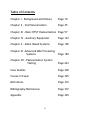
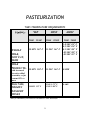
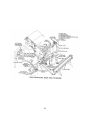


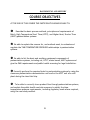
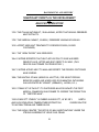

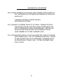
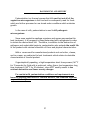


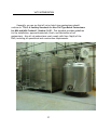
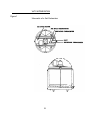
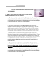
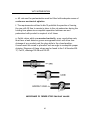
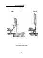
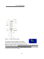

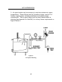
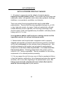
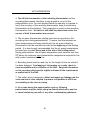

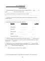
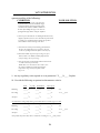


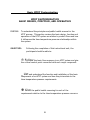

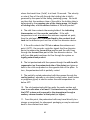
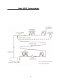
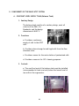
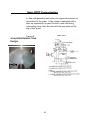
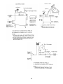

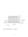
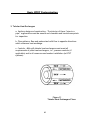
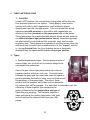
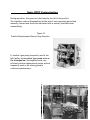
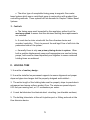
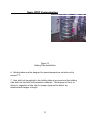
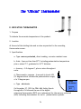
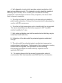
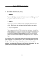
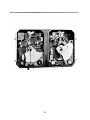
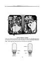

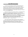

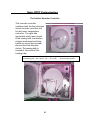
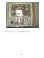
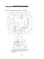

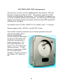
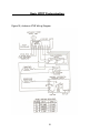
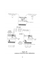
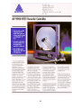
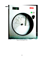


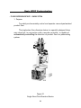
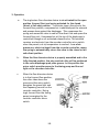
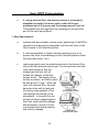
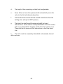

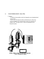
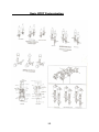

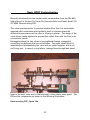

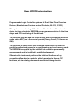

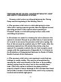
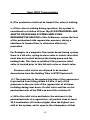
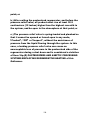
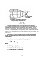
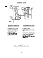
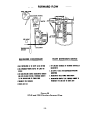
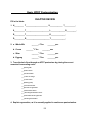
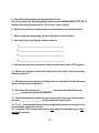
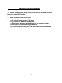
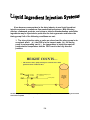

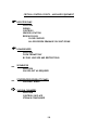
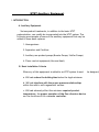
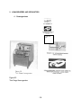
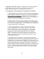
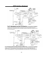
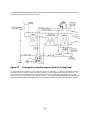
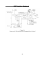
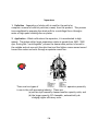
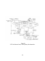
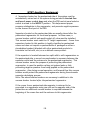
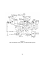
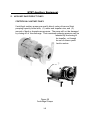
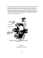
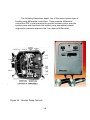
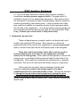
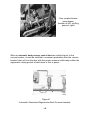
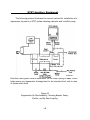
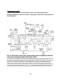
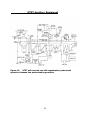


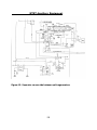
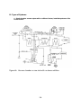
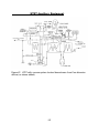
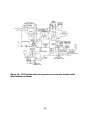
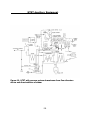


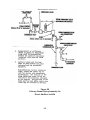
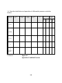


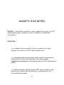
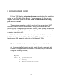
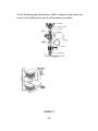

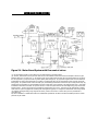
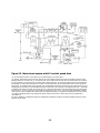
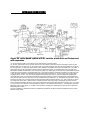
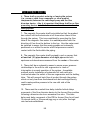
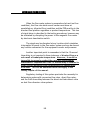


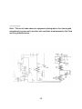
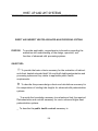


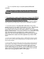
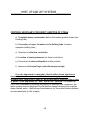
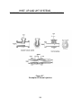
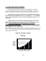


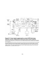

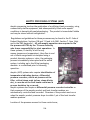

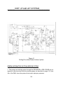


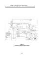
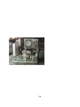
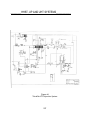


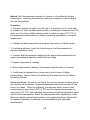
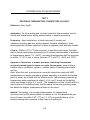
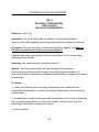
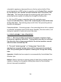


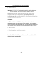
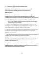

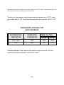
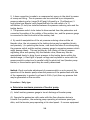
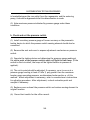


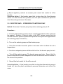

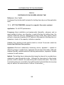

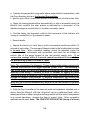
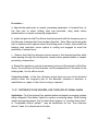
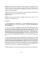
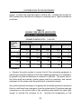
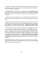
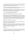
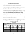
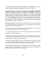
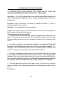
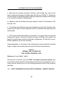
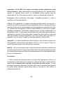
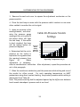
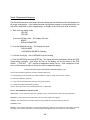

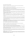
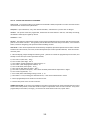


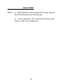


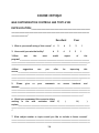


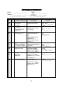
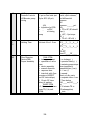
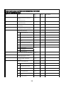
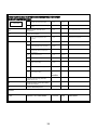


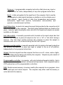
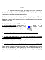
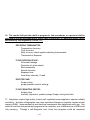
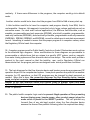
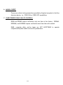
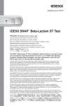
![1127117 - [PROJECT.TOC] - Performance Heating & Plumbing](http://vs1.manualzilla.com/store/data/005895106_1-55e9d6c83dbc31a8ba61d6bb401245cf-150x150.png)