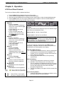
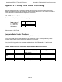
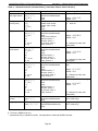
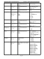
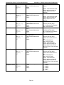
1
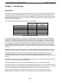
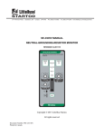
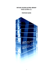
CPX2-173 Rugged Military Grade 6U Rack Mount 17.3-Inch Wide-Screen LCD Display Technical Reference 22009400A Revision Preliminary A June 4, 2014 Warranty The product is warranted against material and manufacturing defects for two years from date of delivery. Buyer agrees that if this product proves defective Chassis Plans’ is only obligated to repair, replace or refund the purchase price of this product at Chassis Plans’ discretion. The warranty is void if the product has been subjected to alteration, neglect, misuse or abuse; if any repairs have been attempted by anyone other than Chassis Plans; or if failure is caused by accident, acts of God, or her causes beyond the control of Chassis Plans. Chassis Plans reserves the right to make changes or improvements in any product without incurring any obligation to similarly alter products previously purchased. In no event shall Chassis Plans be liable for any defect in hardware or software or loss or inadequacy of data of any kind, or for any direct, indirect, incidental or consequential damages arising out of or in connection with the performance or use of the product or information provided. Chassis Plans’ liability shall in no event exceed the purchase price of the product purchased hereunder. The foregoing limitation of liability shall be equally applicable to any service provided by Chassis Plans. Return Policy Products returned for repair must be accompanied by a Return Material Authorization (RMA) number, obtained from Chassis Plans prior to return. Freight on all returned items must be prepaid by the customer, and the customer is responsible for any loss or damage caused by common carrier in transit. Items will be returned from Chassis Plans via Ground, unless prior arrangements are made by the customer for an alternative shipping method To obtain an RMA number, call us at 858-571-4330. We will need the following information: Return company address and contact Model name and model # from the label on the back of the display Serial number from the label on the back of the display Description of the failure An RMA number will be issued. Mark the RMA number clearly on the outside of each box, include a failure report for each board and return the product(s) to our San Diego, CA facility: Chassis Plans. 10123 Carroll Canyon Road San Diego, CA 92131 Attn: Repair Department Trademarks Liability Disclaimer “The Original Industrial Computer Source”, “Systems Engineered to Perform” and Chassis Plans are registered trademarks of Chassis Plans, LLC. IBM, PC/AT, VGA, EGA, OS/2 and PS/2 are trademarks or registered trademarks of International Business Machines Corp. Intel is a registered trademark of Intel Corporation. MS-DOS and Microsoft are registered trademarks of Microsoft Corp. All other brand and product names may be trademarks or registered trademarks of their respective companies. This manual is as complete and factual as possible at the time of printing; however, the information in this manual may have been updated since that time. Chassis Plans reserves the right to change the functions, features or specifications of their products at any time, without notice. Copyright © 2014 by Chassis Plans. All rights reserved. E-mail: [email protected] Web: www.chassis-plans.com Chassis Plans 10123 Carroll Canyon Road • San Diego, CA 92131 Phone: (858) 571-4330 • Fax: (858) 571-6146 • Email: [email protected] This Page Intentionally Blank Chassis Plans CPX2-173 Technical Reference I ndex Table of Contents Chapter 1 ‐ Introduction _______________________________________________________________ 1 Description _______________________________________________________________________________ 1 Table 1 – Display Specifications ____________________________________________________________________ 1 LCD Enhancements _________________________________________________________________________ 2 Figure 1 – EMI Shielding Effectiveness of ITO Coating __________________________________________________ 2 Figure 2 – Optical Stack on LCD ____________________________________________________________________ 2 Figure 3 – Comparison of Reflections with and without Optical Bonding ___________________________________ 3 Figure 4 – Comparison with and without Optical Bonding _______________________________________________ 3 Genesis Based LCD Controllers ________________________________________________________________ 4 Figure 5 – Controller Specifications _________________________________________________________________ 4 Photos ___________________________________________________________________________________ 5 Specifications ______________________________________________________________________________ 6 Enclosure ________________________________________________________________________________________ 6 Display __________________________________________________________________________________________ 6 Display Enhancement Options _______________________________________________________________________ 6 Power Supply Options ______________________________________________________________________________ 6 Environmental ____________________________________________________________________________________ 6 Table 2 – Specifications __________________________________________________________________________ 6 Figure 6 ‐ CCX Outline Drawing ____________________________________________________________________ 7 Chapter 2 – Power Supply Options _______________________________________________________ 9 AC Input Power Supply ______________________________________________________________________ 9 Table 3 ‐ AC Input Supply Specifications _____________________________________________________________ 9 Photo 1 ‐ AC Power Supply _______________________________________________________________________ 9 12VDC Input Transient Filter ________________________________________________________________ 10 Connectors _____________________________________________________________________________________ 10 MIL‐STD‐704/1275 28VDC DC Input ___________________________________________________________ 11 Operating Specifications ___________________________________________________________________________ 11 Connectors _____________________________________________________________________________________ 11 Environmental Specifications _______________________________________________________________________ 11 Table 4 ‐ MIL‐STD‐704 Power Supply Specifications ___________________________________________________ 11 +/‐48VDC Power Supply ____________________________________________________________________ 12 Operating Specifications ___________________________________________________________________________ 12 Connectors _____________________________________________________________________________________ 12 Electrical Specifications ____________________________________________________________________________ 12 Table 5‐ 48VDC Power Supply Specifications ________________________________________________________ 12 Chapter 3 – Ordering Information ______________________________________________________ 13 Part Number Matrix ______________________________________________________________________________ 13 Example Part Numbers ____________________________________________________________________________ 13 Chapter 4 ‐ Installation _______________________________________________________________ 15 Package Contents ________________________________________________________________________________ 15 Table 6 ‐ Package Contents ______________________________________________________________________ 15 Rack Installation __________________________________________________________________________ 16 Figure 7 ‐ Rack Mounting Hole Spacing _____________________________________________________________ 16 Chassis Plans CPX2-173 Technical Reference I ndex Connecting the Display _____________________________________________________________________ 17 Standard Controller Rear Panel Connections ___________________________________________________ 17 Photo 2 – Standard Controller Rear Panel I/O ________________________________________________________ 17 Table 7 ‐ Rear Panel Connections – Standard Controller _______________________________________________ 17 Advanced Controller Rear Panel Connections ___________________________________________________ 18 Photo 3 ‐ Advanced HD/SDI Controller Rear Panel I/O _________________________________________________ 18 Table 8 ‐ Rear Panel Connections – Advanced HD/SDI Controller ________________________________________ 18 Chapter 5 ‐ Operation ________________________________________________________________ 19 LCD Front Panel Controls ___________________________________________________________________ 19 Table 9 ‐ Front Panel Controls ____________________________________________________________________ 19 Standard Controller OSD Menus _____________________________________________________________ 20 Advanced HD/SDI Controller OSD Menus ______________________________________________________ 25 Appendix A – Display Serial Control Programming _______________________________________ 27 RS‐232 Serial control _______________________________________________________________________ 27 Controller Serial Control Functions ___________________________________________________________ 27 Table 10 ‐ Standard Controller Commands to Implement Switch Mount Control Buttons _____________________ 27 Table 11 ‐ Standard Controller Parameter Setting ‐ Immediate, Relative, Reset and Query ____________________ 28 Table 12 ‐ Standard Controller Other Control ________________________________________________________ 38 Table 13 ‐ Hex to ASCII Conversion Table ___________________________________________________________ 40 Appendix B – Auto Color Gain __________________________________________________________ 41 Image B‐1 – Auto Color Gain Example ______________________________________________________________ 41 Appendix C – DVI‐D versus DVI‐I Connectors ______________________________________________ 42 Overview ________________________________________________________________________________ 42 Connectors _______________________________________________________________________________ 42 Appendix D – Ethernet Network Connection ______________________________________________ 43 Connecting a network port to CPX2‐173 _______________________________________________________ 43 Get the IP address using DHCP _______________________________________________________________ 44 Web Console _____________________________________________________________________________ 44 IP Locator ________________________________________________________________________________ 44 Image D‐1 – IP Locator Screen Show _______________________________________________________________ 44 Network configuration _____________________________________________________________________ 44 Image D‐2 – Network Drop Down _________________________________________________________________ 44 Image D‐3 – Network Configure Settings ___________________________________________________________ 45 Connect to a single CPX2‐173 ________________________________________________________________ 45 Table D‐1 – Remote Control ______________________________________________________________________ 45 Image D‐4 – IP Address Locator ___________________________________________________________________ 46 Image D‐5 – IP Address Setting and Enable __________________________________________________________ 46 Connect to multiple CPX2‐173 _______________________________________________________________ 46 Table D‐2 – Remote Control ______________________________________________________________________ 46 Image D‐6 – DHCP Table Screenshot _______________________________________________________________ 47 Image D‐7 – NAT Fowarding Screenshot ____________________________________________________________ 47 Chassis Plans CPX2-173 Technical Reference Chapter 1 - Introduction Chapter 1 - Introduction Description The CPX2-173 is a military-grade high-performance 6U rack mount or panel mount LCD display offering 1920 x 1080 wide-screen high-definition resolution. The CPX2-173 is designed to meet Mil-Std 901D and MIL-STD810G and includes a solid milled aluminum front panel, lightweight 5052-H32 aluminum construction and locking stainless hardware throughout. The CPX2-173 is ideal for mounting in a transit case for adverse environments that would destroy lesser displays. Two versions offer standard brightness or hi-bright for sunlight visibility. Contrast Ratio Viewing Angle (L/R/U/D) Response Time Brightness Backlight Native Resolution Aspect Ratio CPX2-1731 Standard 600:1 80º 40ms 400 cd/m2 LED 1920 x 1080 16:9 CPX2-1732 Hi-Bright 600:1 80º 40ms 1000 cd/m2 LED 1920 x 1080 16:9 Table 1 – Display Specifications The displays are high-performance, long life TFT LCD’s offering a maximum native wide-screen resolution of 1920 x 1080. The displays offer optional optically bonded anti-reflective overlay glass. In addition, an optional laminated 1.1mm soda lime glass with an ITO conductive EMI filter and an additional 1.1mm soda lime glass overlay with anti-reflective (AR) coating. Both glass components are optically bonded to each other, and to the front of the display, for superior viewing clarity and overall ruggedness. A 6mm copper bus bar surrounds the entire glass stack-up and provides consistent grounding. A contrast ratio of approximately 1300:1 is delivered with this ITO/Anti-Reflective glass stack-up. The front surface is an oleophobic anti-reflective coating resistant to fingerprints. The displays offer 16.7 million colors (True Color). The displays provide multiple signal input options including aRGB, DVI-D, HDMI, Display Port, HD-SDI, NTSC, S-Video and Composite Video, depending on the controller. The displays offer a choice of high quality advanced scaling controllers with a Genesis chipset. These are specifically ruggedized controllers offering as standard conformal coating with high shock/vibration and temperature extreme tolerances as well as long life product availability for assured delivery throughout multi-year programs. The Standard Controller offers DVI-D, VGA (aRGB), HDMI, NTSC and CVS. In addition, the Standard Controller supports Picture-In-Picture (PIP) and Picture-By-Picture. The Advanced HD-SDI Controller offers VGA (aRGB), HDMI, Display Port, HD-SDI and 3G HD-SDI. The display is only 6U (10.47-inches) high offering significant rack space savings. It can be rack mounted, panel mounted, or mounted using a VESA adapter via the included VESA hole pattern on the rear of the unit. It is only 2.75-inches deep and power and signal cables exit down so as to not increase depth requirements. As with all Chassis Plans products, a wide variety of custom options can be configured per customer or application specific requirements. Contact your Sales Engineer to discuss your particular requirements. Page 1 Chassis Plans CPX2-173 Technical Reference Chapter 1 - Introduction LCD Enhancements Chassis Plans starts with Grade A Industrial Quality LCD panels selected for optical performance, high reliability and long product life cycle. In order to not only ruggedize the LCD, but to also enhance the mechanical, optical and EMI properties of the finished unit, as an option, Chassis Plans optically bonds one 3mm anti-reflective or two layers of coated 1.1 mm soda-lime float glass to the front of the LCD panel. The first layer is coated with an Indium Tin Oxide (ITO) coating with a surface resistivity of <13.5 ohms/sq. See Figure 1 for attenuation values. 50 45 40 15" LCD 35 17" LCD 30 19" LCD 25 20 30 MHz 75 MHz 100 MHz 150 MHz 200 MHz 300 MHz 500 MHz 700 MHz 1000 MHz Figure 1 – EMI Shielding Effectiveness of ITO Coating There is a Copper conductive buss bar that wraps around the edge of the glass to facilitate conduction from the ITO coating to the front surface of the laminated structure to make a complete electrical shield around the face of the LCD. See Figure 2 for details. C opper B uss B ar A R C o a tin g S o d a L im e F lo a t G la s s O p tic a l In d e x M a tc h in g A d h e s iv e IT O C o a tin g L C D F ra m e LC D Panel And B a c k lig h t Figure 2 – Optical Stack on LCD The second layer of glass is coated with an Oleophobic Anti-Reflective (AR) coating which matches the index of refraction of air to eliminate surface reflections. These layers of coated glass are bonded together with an index matching optical adhesive to eliminate internal reflections caused by the index of refraction mismatch between the soda lime glass and air. This eliminates over 95% of unwanted glare from the screen. Please see Figure 3 below for more details. Page 2 Chassis Plans CPX2-173 Technical Reference Chapter 1 - Introduction Without Optical Bonding Or AR Coating 4.5% 4.5% With Optical Bonding And AR Coating Reflected Light Total 22.5% 0.3% 0.1% 4.5% 0.1% 4.5% 0.1% 4.5% 0.1% Reflected Light Total 0.7% Figure 3 – Comparison of Reflections with and without Optical Bonding The resulting structure in conjunction with the CPX2-1732 Hi-Bright 1000nit panel has greatly enhanced optical characteristics in high ambient light conditions. The optical adhesive used is a silicone RTV and offers other benefits mechanically to the LCD as well. The adhesive remains pliable and therefore acts as a shock absorbing medium for the front of the LCD. Together with the additional layers of glass provides a very rugged composite structure. Another benefit is that should breakage actually occur the shards of glass will be retained together to prevent injury to personnel. The adhesive also prevents any condensation from building up in the air gap between the layers of glass which would cause fogging of the display. Finally, the added mass bonded to the front of the LCD display adds a thermal conduction path to help dissipate the heat generated in the backlights themselves. By eliminating the majority of reflected light, the apparent contrast improves making the display more readable in high bright situations. An alternative to improving the contrast is to increase the back light levels to overpower the reflected light. The downside to this approach is the higher power requirements and higher heat generated by the backlights. Photo Courtesy of GDS Clearview Figure 4 – Comparison with and without Optical Bonding Page 3 Chassis Plans CPX2-173 Technical Reference Chapter 1 - Introduction Genesis Based LCD Controllers The LCD Controller is a key component in any display system and no expense has been spared in specifying the Standard Controller and Advanced HD-SDI Controller Genesis controllers. These are long life revision controlled military grade components. The Genesis chip set is the current gold standard for LCD controllers. The controllers support 3x8-bit 16.7 million colors at up to 1920 x 1200. Refresh rates of 60Hz for WUXGA and UXGA with higher refresh rates for lower resolutions available. Computer input signals of VGA, SVGA, XGA, SXGA, WXGA, UXGA and WUXGA are supported. Video inputs of NTSC, PAL and SECAM are optionally available. DVI inputs supports up to 1920 x 1080 WUXGA 60Hz signals. These ruggedized military grade controllers are rated for operating at -40 to +80 deg C, use low mass tantalum capacitors for maximum vibration and shock tolerance and are conformal coated for extreme ruggedness. The coating is silicone resin conformal coating.(MOD) DEFSTAN 59/47 Issue 4 &UL QMJU2 compliant MTBF for the controllers is in excess of 150,000 to 200,000 hours. Figure 5 – Controller Specifications Page 4 Chassis Plans CPX2-173 Technical Reference Chapter 1 - Introduction Photos Connector details dependent on installed controller Page 5 Chassis Plans CPX2-173 Technical Reference Chapter 1 - Introduction Specifications Enclosure 6U (10.47”) x 3.2” deep Front Panel milled 5052 aluminum alloy Body made of 5052-H32 aluminum alloy All stainless steel hardware All self-locking pressed in fasteners where appropriate Powder coat black, medium texture, for ruggedness Other colors optionally available Designed to Mil-Spec Standards to Satisfy Military, Industrial and Commercial Requirements Compact Enclosure for Limited Depth Installation Weight: 9.7lbs (depending on model & features) Environmental (Designed to meet or exceed) Display 17.3" Wide-Screen TFT LCD 1920 x 1080 Display Colors: 16.7 Million Response Time: 40ms Typical Viewing Angle: 80 deg Contrast Ratio: 600:1 typical native Brightness: 400cd/m2 standard (CPX2-1731), 1000cd/m2 enhanced daylight visibility (CPX21732) Pixel Pitch: 0.1989mm x 0.1989mm Pixel Arrangement: R.G.B Stripe Display Enhancement Options 3mm smudge-resistant anti-reflective coated soda lime float glass,bonded to the LCD panel with optical index matched adhesive Laminate of 1.1mm smudge-resistant anti-reflective coated soda lime float glass panel and a 1.1 mm ITO coated glass panel(<12.5Ω/sq) grounded via a copper buss bar, bonded to the LCD panel with optical index matched adhesive Altitude 10,000 ft. Operational, 30,000 ft. Storage MIL-STD-810, Method 500.5 High Temperature 70°C Operational, 70°C Storage MIL-STD-810, Method 501.5 Low Temperature 0°C Operational, -20°C Storage MIL-STD-810, Method 502.5 Humidity 5-95%, Non-condensing MIL-STD-810, Method 507.5 Blowing Sand and Dust Procedures I and II MIL-STD-810, Method 510.5 Transport Vibration US Highway Truck and Air Transport MIL-STD-810, Method 514.6 Bench Handling Shock Procedure VI, 20G @ 11ms MIL-STD-810, Method 516.6 Power Supply Options AC Input 100 to 260VAC, auto selecting 47-66 HZ 12VDC Input Transient Filter Line transient protection for 12VDC vehicular applications Mil-Std-1275A DC/DC Converter True 1275 compliance for military 28VDC nominal vehicle inputs 18 to 36VDC input 48VDC DC/DC Converter 36 to 75VDC Input Isolated Inputs for +/- input levels See the appropriate power supply section for complete power supply specifications. Table 2 – Specifications Page 6 Chassis Plans CPX2-173 Technical Reference Chapter 1 - Introduction Figure 6 - CCX Outline Drawing Page 7 Chassis Plans CPX2-173 Technical Reference Chapter 1 - Introduction This Page Intentionally Blank Page 8 Chassis Plans CPX2-173 Technical Reference Chapter 2 – Power Supply Options Chapter 2 – Power Supply Options AC Input Power Supply The AC Input Power Supply is a 65W Medical Grade “Brick” style power supply. The output is provided with a circular mil connector for connecting to the LCD Keyboard Drawer. The input accepts a standard IEC 320 plug. A bracket is provided to securely mount the supply in a rack. Alternate AC supplies are available as required by the application or environmental requirements. INPUT Voltage Current Frequency Input Connector 85-264 VAC 1.4 A @ 110 VAC 47 – 63 Hz 3-Pin IEC 320 Receptacle OUTPUT Voltage Max Current Total Regulation Set Point Accuracy Hold-up Time 12VDC 12.5A < +/- 5% < +/- 3% @ 60% Load >12mS @ Full Load, 115VAC Over Voltage Protection Built-in Over Current Protection Built-in Short Circuit Protection Pulsing mode, auto recovery SIZE LXWXH Weight ENVIRONMENTAL Operating Temperature Storage Temperature SAFETY cTUVus UL 60601-1 CSA C22.2 No. 601.1-M90 CB per IEC 60601-1 CE marked to LVD Class I EMI/EMC Emissions Immunity 7.56” x 2.45”” x 1.52” 1.55 lbs Table 3 - AC Input Supply Specifications Photo 1 - AC Power Supply Page 9 0 to 50°C -40 to +85°C CISPR11 and FCC Part 15, Class B EN61000-3-2, -3 EN61000-4-2, -3, -4, -5, -6, -9, -11 Chassis Plans CPX2-173 Technical Reference Chapter 2 – Power Supply Options 12VDC Input Transient Filter The CPX2-173 display consoles require nominal +12VDC at 40W for operation. An EMI line filter is provided to limit EMI emissions and to provide a small measure of input filtering. For operation from unregulated 12VDC (+/-10%) such as in a vehicular or marine environment, front end transient filtering is required to suppress potentially damaging spikes from large inductive loads in the DC circuit (starters, etc.). The xxx 12VDC Input Transient Filter provides an input Transient Protection as well as inductive and capacitive filtering to suppress large input transients. A bridge rectifier provides reverse connection protection. A circuit breaker provides for failure protection and allows the power to be disconnected. Connectors Input Connector Mating Input Connector Pinouts Output Connector Mating Output Connector Pinouts MS3102A-10SL-3P (MIL-C-5015) MS3106A-10SL-3S (Straight) MS3108A-10SL-3S (Right Angle) Pin A – Positive Pin B – Negative Input Pin C – N/C MS3102A-10SL-3S (MIL-C-5015) MS3106A-10SL-3S (Straight) MS3108A-10SL-3S (Right Angle) Pin A – Positive Pin B – Negative Pin C – N/C Page 10 Chassis Plans CPX2-173 Technical Reference Chapter 2 – Power Supply Options MIL-STD-704/1275 28VDC DC Input The ‘C’ option 28VDC Mil-Std-704/1275 DC Input is an internal power supply providing true 704/1275 input specifications allowing reliable operation from nominal 28VDC input mains in a military environment. This supply meets Mil-Std-704A and Mil-Std-1275A (100V for 50mS). Operating Specifications Input Voltage Output Voltage Output Current Output Power 18-36VDC 12.0VDC 5A 75W Electrical Specifications Efficiency Isolation Output and Input to Case EMI Filtering CD101 and CE102 on the input Operating Temperature Storage Temperature 81% 200VDC, Input to Mil-Std-461E, -40°C to +85°C -55°C to +100°C Connectors Input Connector Mating Input Connector Pinouts Output Connector Mating Output Connector Pinouts MS3102A-10SL-4P (MIL-C-5015) MS3106A-10SL-4S (Straight) MS3108A-10SL-4S (Right Angle) Pin A – Positive Pin B – Negative Pin C –N/C MS3102A-10SL-3S (MIL-C-5015) MS3106A-10SL-3S (Straight) MS3108A-10SL-3S (Right Angle) Pin A – Positive Pin B – Negative Pin C– N/C Environmental Specifications Pressure-Altitude Per MIL-STD-810F, Method 500.4, Procedure I and II High Temperature Per MIL-STD-810F, Method 501.4, Procedure I and II Low Temperature Per MIL-STD-810F, Method 502.4, Procedure I Humidity Per MIL-STD-810F, Method 507.4, Procedure I Fungus Per Mil-Std-810F, Method 508.5, Procedure I Salt Fog Per Mil-Std-810F, Method 509.4, Procedure I Sand and Dust Per Mil-Std-810F, Method 510.4, Procedure I and II Explosive Atmosphere Per Mil-Std-810F, Method 511.4, Procedure I Acceleration Per MIL-STD-810F, Method 513.5, Procedure I and II Vibration Per MIL-STD-810F, Method 514.5, Procedure I, Category 1, 4, 7 thru 14 and 16 thru 21 Shock Per MIL-STD-810F, Method 516.5, Procedure I, IV Table 4 - MIL-STD-704 Power Supply Specifications Page 11 Chassis Plans CPX2-173 Technical Reference Chapter 2 – Power Supply Options +/-48VDC Power Supply The xx 48VDC Input Converter provides universal isolated 48VDC input, either positive or negative input. Thus it can be used in a data center with centralized power of +48VDC as well as a central office with -48VDC mains. The system is provided in a rack mountable case with military grade circular connectors. Operating Specifications Input Voltage Output Voltage Output Current Output Power Electrical Specifications Efficiency Isolation 36-75VDC 12.0VDC 10A 120W EMI Filtering Connectors Input Connector Mating Input Connector Pinouts Output Connector Mating Output Connector Pinouts MS3102A-14SL-7P (MIL-C-5015) MS3106A-14S-7S (Straight) MS3108A-14S-7S (Right Angle) Pin A - Positive Pin B – Negative Operating Temperature Storage Temperature MS3102A-10SL-3S (MIL-C-5015) MS3106A-10SL-3S (Straight) MS3108A-10SL-3S (Right Angle) Pin A – Positive Pin B – Negative Pin C– N/C Table 5- 48VDC Power Supply Specifications Page 12 92% 1500VDC, Input to Output and Input to Case Mil-Std-461E, CD101 and CE102 on the input -40°C to +85°C -55°C to +125°C Chassis Plans CPX2-173 Technical Reference Chapter 3 – Ordering Information Chapter 3 – Ordering Information Part Number Matrix CPX2-173[M][ME][S][P]) (M) Standard or Hi-Bright Monitor 1 – Standard 600 cd/m2 2 – Hi-Bright 1,000 cd/m2 (ME) LCD Surface Enhancements A – Bonded EMI Filter and AR cover glass B – Standard w/ no screen enhancements C - Bonded 3mm AR coated cover glass E - Bonded USB Resistive touch screen (S) Video Signal Inputs D4 – Includes VGA, DVI-D, HDMI, Component, Composite G1 - VGA, Dispay Port, HDMI, Component, Composite, HD-SDI (P) Power Supply Option N – No supply provided. Operates from nominal 12VDC +/-5% A – AC input, universal 100-260VAC, 50/60Hz B – 12VDC Front End Transient Filter C – 28VDC Mil-Std-704 Military Grade D – 12VDC for connection to Chassis Plans Chassis Power Plug E – +/-48VDC, Vicor Module Military Grade F – AC input, universal 100-260VAC, 400Hz Example Part Numbers CPX2-1731BD4A – Standard brightness. No LCD enhancements. VGA/DVI/HDMI input. AC Power. CPX2-1732CG1C – Hi-Bright display brightness. Anti-reflective LCD enhancement. Enhanced HD/SDI controller. 28VDC input power. Page 13 Chassis Plans CPX2-173 Technical Reference Chapter 3 – Ordering Information This Page Intentionally Blank Page 14 Chassis Plans CPX2-173 Technical Reference Chapter 4 - Installation Chapter 4 - Installation Package Contents Part Description LCD Keyboard Assembly Power Supply Power Supply Rack Bracket Rack Ruler Rack Slide Hardware Kit (General Devices) Cable Tie, 7-9/16” Long Velcro Tie, Black Cage Nuts Manual, LCD User, CD Manual, LCD Quick Start Guide Checklist DVI Cable, 6-Foot VGA Cable, 6-Foot USB A-A Cable, 6-Foot PS/2 Keyboard/Mouse Cable, 6-Foot Quanty 1 1 (if P/S spec’d in part number) 1 (if P/S spec’d in part number) 1 1 8 6 8 1 1 1 1 1 1 2 Table 6 - Package Contents Notes: 1. Power Cord Kit – For the AC input supplies, a standard 6-foot North American IEC-320 power cord is provided. For the DC input supplies, a kit is provided with a mating Mil Circular connector, backshell, and pins allowing the user to fabricate an appropriate cable for the intended application. For volume orders, Chassis Plans can provide pre-fabricated power cables per the end use specifications. Page 15 Chassis Plans CPX2-173 Technical Reference Chapter 4 - Installation Rack Installation To mount the CPX2-173 in a rack, it is first important you identify the correct holes to mount to. Please see the following illustration. Note that a ‘U’ starts between the holes that are ½” apart. One very common problem is trying to install into the wrong holes. Because there are multiple styles of racks, it is not possible to provide detailed instructions on mounting the equipment. However, there are general instructions at http://www.chassis-plans.com/PDF/Rack_Slide_Use.pdf for rack installation which should help. Figure 7 - Rack Mounting Hole Spacing Chassis Plans offer free Rack Rulers to assist in installing equipment into racks. You should have received one with your order. To request more, fill out the short form at http://www.chassis-plans.com/form_rack_ruler.html and we’ll send you as many as you want. These are invaluable for installing systems into racks. Page 16 Chassis Plans CPX2-173 Technical Reference Chapter 4 - Installation Connecting the Display The CPX2-173 provide for two controllers with rear panel details provided below. Standard Controller Rear Panel Connections The Standard Controller provides for DVI and VGA inputs. In addition, the rear of the display provides for Keyboard and Pointing Device outputs plus a Circular Mil connector for power connection. The Standard Controller offers the following features: Inputs: Analog RGB: 60Hz at WUXGA, UXGA 75Hz at SXGA, WXGA, XGA, SVGA, VGA With auto detect of Digital Separate Sync, Sync-On-Green & Composite Sync. Auto detects VGA-WUXGA, interlaced & non-interlaced DVI-D/HDMI: 60Hz at WUXGA 75Hz at SXGA, WXGA, XGA, SVGA, VGA Image Scaling: Up / down scaling to fit input to native panel resolution of 1280x1024. Video: NTSC /PAL/SECAM (Interlaced), Composite Video, S-video, SD Component (YCbCr), HD Component (YPbPr) Image Control: Brightness, Contrast, Saturation, Hue, Frequency, Phase, Color temperature, Image position, Hue, Gamma. Other Features: Auto picture setup, Auto RGB calibration, Auto source seek, OSD timeout, OSD position, Input source select, OSD menu lock, Direct key for brightness level adjustment. Photo 2 – Standard Controller Rear Panel I/O Legend Function Connector VGA aRGB Input HD15 Female Display Port Display Port Input Display Port HDMI HDMI Input HDMI SDI Input HD/SDI Input BNC Reclocked SDI Output HD/SDI Reclocked Output BNC RS232 Control Port RS232 Remote Control DB9 Female Touch Screen Touch Screen Output USB USBFTV22G (Optional) 12VDC Power Input Power, 12VDC +/-5% Circular Mil N/S 3102A-10SL-3P Circuit Breaker Power Interruption Push to reset Table 7 - Rear Panel Connections – Standard Controller Page 17 Chassis Plans CPX2-173 Technical Reference Chapter 4 - Installation Advanced Controller Rear Panel Connections The Advanced Controller provides for HD/SDI, VGA analog, HDMI, Display PortComposite and S-Video video inputs. The Advanced Controller also supports Picture-In-Picture (PIP) allowing a video input (Composite or S-Video) image to be laid on top of either a VGA or DVI input. The Advanced HD/SDI Controller offers the following features: Inputs: Analog RGB: 60Hz at WUXGA, UXGA, SXGA, WXGA, XGA, SVGA, VGA With auto detect of Digital Separate Sync,Sync-On-Green & Composite Sync. Auto detects VGA-WUXGA, interlaced & non-interlaced HDMI 1.3: 60Hz at WUXGA, UXGA, SXGA, WXGA, XGA, SVGA, VGA, 1080p, 1080i, 720p, 576p, 480p Display: 60Hz at WUXGA, UXGA, SXGA, WXGA, XGA, SVGA, VGA, 1080p, 1080i, 720p, 576p, 480p Port 1.1a SDI: 576i50 (PAL), 480i60 (NTSC), 720p60/59.94/50 (4:2:2), 1080i60/59.94/50 (4:2:2), 1080p60/50 (4:2:2) Features: Image Up-Scaling, Image Down-Scaling, Auto picture setup, Auto RGB calibration, Auto source seek, OSD timeout, OSD position, OSD menu rotation, OSD transparency, select input source, Volume control, On board temperature reporting Image Control: Brightness, Contrast, Sharpness, Color, Clock, Phase, Color temperature, Image position, Gamma SDI Reclocked Output SDI RS232 Display Input Control Port HDMI VGA Port Touch Screen* Circuit Breaker Power Photo 3 - Advanced HD/SDI Controller Rear Panel I/O Legend VGA Display Port HDMI SDI Input Reclocked SDI Output RS232 Control Port Touch Screen 12VDC Power Circuit Breaker Function Connector aRGB Input Display Port Input HDMI Input HD/SDI Input HD/SDI Reclocked Output RS232 Remote Control Touch Screen Output USB Input Power, 12VDC +/-5% Power Interruption HD15 Female Display Port HDMI BNC BNC DB9 Female USBFTV22G (Optional) Circular Mil N/S 3102A-10SL-3P Push to reset Table 8 - Rear Panel Connections – Advanced HD/SDI Controller Page 18 Chassis Plans CPX2-173 Technical Reference Chapter 5 – Operation & OSDs Chapter 5 - Operation LCD Front Panel Controls The On Screen Display (OSD) is adjusted as follows: 1. 2. 3. 4. Press the Menu Button located on the front of the monitor. Use the buttons described below to maneuver around the Menu. Select the desired OSD Menu from the Menu Screen Shots below to make the desired adjustment(s). Press the Menu button to exit out of the OSD Menu when complete or wait for the OSD window to automatically close as set by the OSD Time Out setting. Power: Turns the Unit On and Off Adjust ▲: o Hot Key 1 Increase o When the cursor is not showing in sub menus, moves selection right between top tabs. o Cursor showing in sub menus, adjusts setting up. o Cursor on sub-sub menu (► showing), enters sub-sub menu. (See Select ▲ below to escape). o Toggles Off to On Adjust ▼: o Hot Key 1 Decrease o When the cursor is not showing in sub menus, moves selection left between top tabs. o Cursor showing in sub menus, adjust setting down o Toggles On to Off Select ▲: o Hot Key 2 Increase o Moves the cursor up. o When in a sub-sub menu, repeatedly press to move to the previous menu level. (See Adjust ▲ above) Select ▼: o Hot Key 2 Decrease. o Moves the cursor Down. Menu o Opens or closes the OSD menu o See Note 1 below for additional information. Brightness ▲: o Increases the screen brightness. Brightness ▼: o Decreases the screen brightness. Hot Keys Hot Keys are defined in the Utility/Hot Key menu and allow single button access to the defined function. Adjust ▲ and ▼ - Hot Key 1 Up and Down Select ▲ and ▼ - Hot Key 2 Up and Down Display Auto Adjust Pressing Auto/Exit will perform a auto display adjustment when in aRGB mode. This automatically adjusts the Phase and Clock for the est displayed image. To save your changes, press the front panel Menu button. Alternatively, changes are saved if no buttons are pressed and the OSD times out returning back to the display. Notes On the Menu Buttons – 1. The Menus are context sensitive in that only adjustments pertaining to the selected input will be displayed. For example, if DVI is selected for the input, then items such as Hue will not be adjustable. 2. Pressing the Menu button returns to the previously opened menu. Notes on Hot Keys 1. Hot Keys allow single button selection of a function. 2. Definition of the Hot Keys is set in the Utility menu. Thus, for example, if the Adjust keys are set up for Input Source, pushing the Up button rolls Up through the Input Sources and pushing the Down button rolls Down through the Input Sources. 3. The Hot Keys display in the upper left of the screen when pushed. Note on Factory Default – Green Normal Operation 1. Under the Utilities Menu, a selection is available to return Red Power On but no input signal the board setting to the factory defaults. Off No power or display turned off Table 9 - Front Panel Controls Page 19 Chassis Plans CPX2-173 Technical Reference Chapter 5 – Operation & OSDs Standard Controller OSD Menus Page 20 Chassis Plans CPX2-173 Technical Reference Chapter 5 – Operation & OSDs Page 21 Chassis Plans CPX2-173 Technical Reference Chapter 5 – Operation & OSDs Page 22 Chassis Plans CPX2-173 Technical Reference Chapter 5 – Operation & OSDs Page 23 Chassis Plans CPX2-173 Technical Reference Chapter 5 – Operation & OSDs Page 24 Chassis Plans CPX2-173 Technical Reference Chapter 5 – Operation & OSDs Advanced HD/SDI Controller OSD Menus Page 25 Chassis Plans CPX2-173 Technical Reference Chapter 5 – Operation & OSDs Page 26 Chassis Plans CPX2-173 Technical Reference Appendix A – Display Serial Control Programming Appendix A – Display Serial Control Programming Both LCD controllers provide for remote serial RS232 control through the rear panel Control Port as shown below. The Standard Controller also provides for control through an Ethernet port. The following command set remains the same for Ethernet control as compared to Serial control. RS-232 Serial control Baud rate 2400, 8 bits, 1 stop bit and no parity 1 4 3 6 7 8 5 9 Mating face of RS-232 DB9 Male PIN# 2 3 5 Description RS-232 Rx Data RS-232 Tx Data Ground Mating connector : DB9 Female Controller Serial Control Functions The OSD functions are controlled through the following RS-232 commands. The RS-232 program can be custom-tailored to fit the application or it can be used as provided by Chassis Plans on request. Please contact Chassis Plans for additional information. Note: Not all Serial Control functions are supported in the Advanced HD/SDI controller. In the following table, functions not supported for the Advanced HD/SDI Controller are indicated with a ‘*’ in the Function column. Table 10 - Standard Controller Commands to Implement Switch Mount Control Buttons Function OSD Menu Lock Command 0xf6 0xf7 0xfa Description OSD menu Lock Off / OSD menu Lock On Menu button pressed Select down button pressed Menu Select-down button Select-up button Right/+ button Left/- button Button equivalent Button equivalent 0xfb 0xfc 0xfd Select up button pressed Right/+button pressed Left/- button pressed Button equivalent Button equivalent Button equivalent Page 27 Acknowledge (if enabled) Button equivalent Chassis Plans CPX2-173 Technical Reference Appendix A – Display Serial Control Programming Table 11 - Standard Controller Parameter Setting - Immediate, Relative, Reset and Query Function Volume control left+right channel Volume control on/off (mute) Brightness control Contrast control all channels Saturation control* Hue control* Phase (tuning) control Image H position Command 0x80, “a” | “A”, nn | “+” | “-” | “r” | “R” | “?” 0x80, “m” | “M”, “0” | “1” | “r” | “R” | “?” 0x81, nn | “+” | “-” | “r” | “R” | “?” “m” “n” “i” , ss, nn “o”, ss, Description Set audio (L+R) volume = value/increment/decrement Reset Query 0x82, “a” | “A”, nn | “+” | “-” | “r” | “R” | “?” “m” “n” “i ” , ss, nn “o”, ss, 0x83, nn | “+” | “-” | “r” | “R” | “?” “m” “n” “i” , ss, nn “o”, ss, 0x84, nn | “+” | “-” | “r” | “R” | “?” “m” “n” “i” , ss, nn “o”, ss, Set all contrast = value/increment/decrement Reset Query Maximum query *1 Minimum query *1 Set, Source, value *1 Query, Source *1 Set color = value/increment/decrement Reset Query Maximum query *1 Minimum query *1 Set, Source, value *1 Query, Source *1 Set tint = value/increment/decrement Reset Query Maximum query *1 Minimum query *1 Set, Source, value *1 Query, Source *1 0x85, nn | “+” | “-” | “?” 0x86, nnnn | “+” | “-” | “?” Set dot clock phase = value/increment/decrement Query Set img_hpos = value/increment/decrement Query Disable audio output. Enable audio output. Reset Query Set brightness = value/increment/decrement Reset Query Current Source Maximum query *1 Minimum query *1 Set, Source, value *1 Query, Source *1 Acknowledge (if enabled) volume Range : “0””0”-“1””E” Default : “0””F” “0” - audio off (muted). “1” - audio on. Brightness. Range : “4””E”-“B””2” Default : “8””0” ss - reference by Input main select(0x98) Contrast Range : “1””C”-“E””4” Default : “8””0” ss - reference by Input main select(0x98) PAL/NTSC color (In video mode only ) Range : “0””1”-“F””F” Default : “8””0” ss - reference by Input main select(0x98) NTSC tint (In NTSC mode only) Range : “5””3”-“9””F” Default : “7””9” ss - reference by Input main select(0x98) Dot clock phase. (In PC mode only) Image horizontal position. (In PC mode only) # - Function in ARGB mode only * - Implemented only in standard controller. Not applicable to Advanced HD/SDI Controller. Page 28 Chassis Plans CPX2-173 Technical Reference Image V position Appendix A – Display Serial Control Programming 0x87, nnnn | “+” | “-” | “?” 0x8a, nn | “+” | “-” | “r” | “R” | “?” 0x8b, nnnn | “+” | “-“ | “?” 0x8c, “0” | “1” | “2” | “3” | “9” | “A” | “B” | “C” | “D” | “r” | “R” | “?” Set img_vpos = value/increment/decrement Query Set sharpness = value/increment/decrement Reset Query Set frequency = Value/increment/decrement Query Set graphic image scaling mode = value Reset Query 0x90, nnn | “+” | “-” | “r” | “R” | “?” 0x91, nnn | “+” | “-” | “r” | “R” | “?” 0x92, n | “+” | “-” | “r” | “R” | “?” 0x93, nn | “+” | “-” | “r” | “R” | “?” Set osd_hpos = value/increment/decrement Reset Query Set osd_vpos = value/increment/decrement Reset Query Set OSD transparency = value/increment/decrement Reset Query Select menu timeout = value/increment/decrement Reset Query Select OSD Language* 0x95, n| “r” | “R” | “?” Select language = English, Chinese,… Reset Query Input main select 0x98, nn | “+” | “-” | “r” | “R” | “?” Select input main = PC or VIDEO or next available Reset Query Sharpness Frequency Scaling Mode* OSD H position OSD V position OSD Transparency* OSD menu timeout Page 29 Image vertical position. (In PC mode only) Sharpness. (Video Mode Source only) Range : “F””4”-“0””C” Default : “0””0” Graphic mode H active size (in pixels) Image expansion on/off. “0” – 1:1 “1” – fill screen “2” – fill to aspect ratio “9” – 4:3 “A” – 16:9 “B” – 16:10 “C” – 2.35:1 “D” – 2:1 OSD horizontal position. Range : “0””0”-“F””F” Default : “8””0” OSD vertical position. Range : “0””0”-“F””F” Default : “8””0” OSD transparency. “0” – ON “1” - OFF OSD menu timeout value. “0””0” – Continuous. value – Round up to nearest available step. if value > max available step, set it to the max available step. Range : “0””5”-“3””C” Default : “0””A” “0” – English. “2” - French “3” – Spanish “6” - German “8” – Chinese Main selected. “0x41,0x31” ARGB “0x42,0x31” Composite* “0x42,0x32” Composite2* “0x43,0x31” S-video* “0x43,0x32” S-video2* “0x44,0x31” Component* “0x44,0x32” Component2* “0x45,0x31” HDSDI “0x45,0x32” HDSDI2 “0x46,0x31” DVI “0x48,0x31” HDMI “0x48,0x31” Display Port Chassis Plans CPX2-173 Technical Reference Appendix A – Display Serial Control Programming Auto Source Seek* 0x99, nn , “0” | “1” | “?” | ”o” Set Auto source enable = *1 Source Disable/ Enable Query Valid Source query “nn” = “0x41,0x31”- ARGB “0x42,0x31”- Composite “0x42,0x32”- Composite 2 “0x43,0x31”- S-video “0x43,0x32”S-video 2 “0x44,0x31”Component “0x44,0x32”Component 2 “0x45,0x31”HDSDI “0x45,0x32”- HDSDI2 “0x46,0x31”- DVI “0x48,0x31” HDMI Source Layout* 0x9a, n| “r” | “R” | “?” Select source layout = Single, PIP, PBP, PBPT Reset, Query Query: “0”- Single “1”- Picture in Picture (PIP) “2”Picture by Picture (PBP) “3”Picture by Picture Tall (PBPT) Video System (Composite, Svideo and Component Only)* 0x9b, “0” | “1” | “2” | “3” | “r” | “R” | “S” | “s”| “?” Set video system = Auto/NTSC/PAL/SECAM Reset Video State Query Query Query “0” – Auto. “1” – NTSC_M_358 “2” – PAL_N_443 “3” – SECAM “4” – NTSC_M_443 “5” PAL_M_358 “7” – PAL_M_443 “9” – PAL_N_358 GAMMA value select 0x9d, n| “r” | “R” “?” Select GAMMA value = Value Reset Query Auto power off* 0x9f, “0” | “1” | “r” | “R” | “?” Set power down option = On/Off Reset Query “0” – Off. “1” – On. Hotkey 1* 0xa0, “1”, n | “r” | “R” | “?” Set Hotkey 1= Value Reset Query “1” – volume. “2” – brightness. “3” – contrast. “4” – colour. “5” – input source. “7” – zoom “8” – freeze “9” – PIP “B” – No function “D” – PIP Swap “E” – Aspect Ratio “G” – Hue “H” – Backlight “I” – Auto Picture Setup Page 30 Video State Query GAMMA value: “0” – 1.0, “1” – 1.6 “2” – 2.2, “3” – User Defined “4” – 1.7, “5” – 1.8, “6” – 1.9, “7” – 2.0, “8” – 2.1, “9” – 2.3, “A” – 2.4, “B” – 2.5, “C” – 2.6, “D” – 0.6, “E” – 0.7, “F” – 0.8, “G” – 0.9, “H” – 1.1, “I” – 1.2, “J” – 1.3, “K” – 1.4, “L” – 1.5 Chassis Plans CPX2-173 Technical Reference Appendix A – Display Serial Control Programming Hotkey 2* 0xa0, “2”, n| “r” | “R” | “?” Set Hotkey 2 = value Reset Query Runtime counter* 0xa1, nnnnn | “r” | “R” | “?” 0xa2, nn | “+” | “-” | “r” | “R” | “?” 0xa3, nn | “+” | “-” | “r” | “R” | “?” 0xa4, nnn | “+” | “-” | “r” | “R” | “?” 0xa5, nnn | “+” | “-” | “r” | “R” | “?” 0xa6, nn | “r” | “R” | “?” runtime counter value = nnnnn (* 0.5 hour) Reset Query Set PIP window brightness = value/increment/decrement Reset Query Set PIP window contrast = value/increment/decrement Reset Query Set PIP_hpos = value/increment/decrement Reset Query Set PIP_vpos = value/increment/decrement Reset Query Select PIP window size = PIP window size value Reset Query 0xa7, n| “r” | “R” | “?” Select input main = Video source value Reset Query PIP brightness control* PIP contrast control* PIP H position* PIP V position* PIP window size select* PIP source select* “1” – volume. “2” – brightness. “3” – contrast. “4” – colour. “5” – input source. “7” – zoom “8” – freeze “9” – PIP “B” – No function “D” – PIP Swap “E” – Aspect Ratio “G” – Hue “H” – Backlight “I” – Auto Picture Setup Runtime = nnnnn. PIP window brightness. Range : “4””E”-“B””2” Default : “8””0” PIP window contrast. Range : “1””C”-“E””4” Default : “8””0” PIP window horizontal position. Range : “0””0””0”-“0””6””4” Default : “0””5””5” PIP window vertical position. Range : “0””0””0”-“0””6””4” Default : “0””1””4” Main selected. PIP off if “nn” = “0””0”. “0””0”~”1””2” “0””0” ~ “1””2” “1””9” : Size by Size “1””A” : Size by Size Tall Main selected. 0x40 0x30 : PIP OFF 0x41, 0x31 : ARGB 0x42, 0x31 : Composite 0x43, 0x31 : S-video 0x44, 0x31 : Component 1 0x45, 0x31 : HDSDI 1 0x46, 0x31 : DVI 0x42, 0x32 : Composite 2 0x43, 0x32 : S-video 2 0x44, 0x32 : Component 2 0x45, 0x32 : HDSDI 2 Zoom level* 0xa8, nnnn | “+” | “-” | “r” | “R” | “?” Set Zoom level = value/increment/decrement Reset Query Page 31 “0x48,0x31” HDMI Zoom level. Min : 0x30 0x30 0x30 0x30 (Default) Max : 0x30 0x30 0x41 0x33 Chassis Plans CPX2-173 Technical Reference Zoom H position* Appendix A – Display Serial Control Programming 0xa9, nnnn | “+” | “-” | “r” | “R” | “?” Set Zoom_hpos = value/increment/decrement Reset Query 0xaa, nnnn | “+” | “-” | “r” | “R” | “?” Set Zoom_vpos = value/increment/decrement Reset Query Horizontal Size* 0xad, Vertical Size* nnn | “+” | “-” | “r” | “R” | “?” 0xb0, Horizontal Pan* nnn | “+” | “-” | “r” | “R” | “?” 0xb1, Set horizontal size for Aspect Size = value/increment/decrement Reset Query Set Vertical Size for Aspect Size = value/increment/decrement Reset Query Set horizontal pan position for Aspect Size = value/increment/decrement Reset Query Zoom V position* nnn | “+” | “-” | “r” | “R” | “?” Vertical Pan* Colour temperature select 0xb2, nnn | “+” | “-” | “r” | “R” | “?” Set Vertical pan position for Aspect Size = value/increment/decrement Reset Query 0xb3, n| “r” | “R” | “?” Select colour temperature = value Reset Query Page 32 Zoom window horizontal position. Default : 0x30 0x30 0x30 0x30 The min and max values will change depends on input resolution. Zoom window vertical position. Default : 0x30 0x30 0x30 0x30 The min and max values will change depends on input resolution. Scalar horizontal stretch PAL(576i) / NTSC (480i) : Min : 0x30 0x30 0x30 (Default) Max : 0x30 0x46 0x30 Scalar vertical stretch. PAL(576i) / NTSC (480i) : Min : 0x30 0x30 0x30 (Default) Max : 0x30 0x46 0x30 Scalar horizontal pan position PAL(576i) / NTSC (480i) : Assume max H-Size & max Vsize : Min : 0x46 0x38 0x38 Max : 0x30 0x37 0x38 Default : 0x30 0x30 0x30 The min and max values will change depends on different value of H-Size, V-Size and input resolution. Scalar vertical pan position PAL(576i) / NTSC (480i) : Assume max H-Size & max Vsize : Min : 0x46 0x38 0x38 Max : 0x30 0x37 0x38 Default : 0x30 0x30 0x30 The min and max values will change depends on different value of H-Size, V-Size and input resolution. Main selected. “0” – 9500K. “1” – 8000K. “2” – 6500K. “3” – 5000K “4” - User Chassis Plans CPX2-173 Technical Reference Red level for selected colour temperature 0xb4, nn | “+” | “-” | “r” | “R” | “?” “m” “n” “i” , ss, c, nn “o”, ss, c Green level for selected colour temperature 0xb5, nn | “+” | “-” | “r” | “R” | “?” “m” “n” “i” , ss, c, nn “o”, ss, c Blue level for selected colour temperature Graphic horizontal resolution enquiry* Graphic vertical resolution* Graphic horizontal sync frequency enquiry* Graphic vertical sync frequency enquiry 0xb6, nn | “+” | “-” | “r” | “R” | “?” “m” “n” “i” , ss, c, nn “o”, ss, c 0xb7 0xb8 0xb9 0xba Appendix A – Display Serial Control Programming Set the level of the red channel for the selected colour temp. = value/increment/decrement Reset Query Maximum query *1 Minimum query *1 Set, Source, Temperature Group, value *1 Query, Source *1 Set the level of the green channel for the selected colour temp. = value/increment/decrement Reset Query Maximum query *1 Minimum query *1 Set, Source, Temperature Group, value *1 Query, Source *1 Set the level of the blue channel for the selected colour temp. = value/increment/decrement Reset Query Maximum query *1 Minimum query *1 Set, Source, Temperature Group, value *1 Query, Source *1 Horizontal resolution (in pixels) in 3 digit hex number Vertical resolution (in lines) in 3 digit hex number Horizontal sync frequency (in units of 100Hz) in 3 digit hex number Vertical sync frequency (in units of Hz) in 3 digit hex number and 1 char OSD status enquiry* 0xbb Status of OSD Display Video Source Select* 0xbc, “?” | “0” | “1” Display Video source select Query Name of video source not displayed. After switching to a new video source, the name of the video source is displayed for 5 seconds. Page 33 Red level for selected colour temperature. Range : “9””C”-“F””F” Default : “E””C” c – reference by Color Temperature ss - reference by Input main select(0x98) Green level for selected colour temperature Range : “9””C”-“F””F” Default : “E””C” c – reference by Color Temperature ss - reference by Input main select(0x98). Blue level for selected colour temperature. Range : “9””C”-“F””F” Default : “E””C” c – reference by Color Temperature ss - reference by Input main select(0x98). “nnn” = horizontal resolution “nnn” = vertical resolution “nnn” = horizontal frequency “nnnn” = vertical frequency nnn = 3 digit hex c= “i” or “p” interlace or Progressive 0xba added the interlace(i) or Progressive(p) feedback. “0” – OSD turned off “1” – OSD turned on “2” – Text Overlay on “3” – Display Mark on “4” – Screen Marker on “0” – Disabled. “1” – Enabled. Chassis Plans CPX2-173 Technical Reference Appendix A – Display Serial Control Programming OSD turn off* 0xbd Turn off the OSD. “0” – fail. “1” – successful. Set gamma data for user defined gamma curve* 0xbf, mm, c, “?” Query gamma data for color c index mm ( c = 0 for color Red, c=1 for color Green, c=2 for color Blue) Set user gamma curve to linear Set gamma data for color c index mm. (If c= 3, then gamma data for red, green & blue will be set at the same time.) “nn” = gamma data “0” – Not Installed “1” – Installed “?” – Not Support “nn” = Revision number 0xbf, “R” | “r” 0xbf, mm, c, nn Query External Memory* 0xcb, “2” Check External Menory 24c256 Query Revision Number* 0xcb, “3” Read Revision Number Backlight control 0xe0, nn | “+” | “-” | “R” | “r” | “?” Set Backlight = value/increment/decrement Reset Query Backlight On/Off Backlight Off / Backlight On /Status Color Monochrome mode selection (Output Channel Select)* 0xe1, “0” | “1” | “R” | “r” ”?” “S” | “s” 0xe2 “0” | “1” | “2” | “3” | | “4” | “5” | “6” | “R” | “r”| ”?” PIP Swap* 0xe3 Backlight D/A / PWM* 0xe5 “0” | “1” | “R” | “r” ”?” Off/ Blue Only/ Red Only/ Green Only/ Blue Mono/ Red Mono/ Green Mono/ Swap Main and PIP source Set : PWM or D/A Reset Query Page 34 “1” “nn” = gamma data Backlight. Range: D/A : “0””0” ~ “1””6” 100Hz : “0””0” ~ “8””A” 120Hz : “0””0” ~ “7””3” 140Hz : “0””0” ~ “6””3” 160Hz : “0””0” ~ “5””6” 180Hz : “0””0” ~ “4””D” 200Hz : “0””0” ~ “4””5” 220Hz : “0””0” ~ “3””E” 240Hz : “0””0” ~ “3””9” 260Hz : “0””0” ~ “3””5” 280Hz : “0””0” ~ “3””1” 300Hz : “0””0” ~ “2””E” 320Hz : “0””0” ~ “2””B” 340Hz : “0””0” ~ “2””8” 360Hz : “0””0” ~ “2””6” 380Hz : “0””0” ~ “2””4” 400Hz : “0””0” ~ “2””2” 420Hz : “0””0” ~ “2””0” 440Hz : “0””0” ~ “1””F” “0” – Backlight Off “1” – Backlight On. “?” – Backlight On/Off Query “S”|”s” – Backlight Status Query “0” – Off “1” – Blue Only “2” – Red Only “3” – Green Only “4” – Blue Mono “5” – Red Mono “6” – Green Mono "0" - Fail. "1" - Successful. “0” – PWM “1” – D/A Chassis Plans CPX2-173 Technical Reference Backlight PWM Frequency* Backlight Invert* Red Offset for selected colour temperature* Green Offset for selected colour temperature* 0xe6, nnn | “+” | “-” | “R” | “r” | “?” 0xe7 “0” | “1” | “R” | “r” ”?” 0xe8, nn | “+” | “-” | “r” | “R” | “?” “m” “n” “i” , ss, c, nn “o”, ss, c 0xe9, nn | “+” | “-” | “r” | “R” | “?” “m” “n” “i” , ss, c, nn “o”, ss, c Blue Offset for selected colour temperature* 0xea, nn | “+” | “-” | “r” | “R” | “?” “m” “n” “i” , ss, c, nn “o”, ss, c PIP Window Blend Level* 0xed, nn | “+” | “-” | “R” | “r” | “?” Appendix A – Display Serial Control Programming Set Backlight PWM Frequency = value/increment/decrement Reset Query Set On or Off Reset Query Set the Offset of the red channel for the selected colour temp. = value/increment/decrement Reset Query Maximum query *1 Minimum query *1 Set, Source, Temperature Group, value *1 Query, Source *1 Set the Offset of the green channel for the selected colour temp. = value/increment/decrement Reset Query Maximum query *1 Minimum query *1 Set, Source, Temperature Group, value *1 Query, Source *1 Set the Offset of the blue channel for the selected colour temp. = value/increment/decrement Reset Query Maximum query *1 Minimum query *1 Set, Source, Temperature Group, value *1 Query, Source *1 Select PIP Transparency Level PIP Transparency value Reset Query Page 35 +/- 20Hz Value 100Hz : “0”,”6”,”4” 120Hz : “0”,”7”,”8” 140Hz : “0”,”8”,”C” 160Hz : “0”,”A”,”0” 180Hz : “0”,”B”,”4”’ 200Hz : “0”,”C”,”8” 220Hz : “0”,”D”,”C” 240Hz : “0”,”F”,”0” 260Hz : “1”,”0”,”4” 280Hz : “1”,”1”,”8” 300Hz : “1”,”2”,”C” “0” – Off “1” – On Red Offset for selected colour temperature. c – reference by Color Temperature ss - reference by Input main select(0x98) Green Offset for selected colour temperature. c – reference by Color Temperature ss - reference by Input main select(0x98) Blue Offset for selected colour temperature. c – reference by Color Temperature ss - reference by Input main select(0x98) PIP Transparency “0”F” = 6.25% “0”E” = 12.5% “0”D” = 18.75% “0”C” = 25% “0”B” = 31.25% “0”A” = 37.5% “0”9” = 43.75% “0”8” = 50% “0”7” = 56.25% “0”6” = 62.5% “0”5” = 68.75% “0”4” = 75% “0”3” = 81.25% “0”2” = 87.5% “0”1” = 93.75% “0”0” = 100%. Chassis Plans CPX2-173 Technical Reference PIP Window Auto Off* ScreenMarker* CenterMarker* “0xee”, “0x41” “0” |”1” “?” “0xee”, “0x42” “0” |”1” “0xee”, “0x43” “0” |”1” Appendix A – Display Serial Control Programming Auto Off / Auto On Query Screen Marker Off / Screen Marker On AspectMarker* “0xee”, “0x44” “0” |”1” Center Marker Off / Center Marker On Preliminary 4:3 /16:9 Marker Background Transparency* “0xee”, “0x45” “0” |”1” |”2” |”3” Preliminary 0% /25%/50%/95% Safe Area Marker* “0xee”, “0x47” “0x53”~”0x63” Preliminary 80%~99% IR Lock* “0xee”, “0x48” n | “0” | “1” | “r” | “R” | “?” “0xee”, “0x4A” “0” | “1” | “R” | “r” ”?” “S” | “s” “0xee”, “0x4B” “0” |”1” “0xee”, “0x4C” “0” |”1” “0xee”, “0x4D” “0” |”1” IR Lock Disable / IR Lock Enable Reset Query “0xee”, “0x70” “A””0” |”A””1” 0xef, “0” | “1” | “2” ”?” Select Static IP or DHCP mode Light Detector* Safe Area Marker Enable* Aspect Marker Enable* Display real time clock** Static IP or DHCP mode switching*** Custom Sizing* “0”- Off “1”- On Light Detector Off / Light Detector On Light Detector On/Off Query Light Detector Value Query Safe Area Marker Off / Safe Area Marker On Aspect Marker Off / Aspect Marker On Real Time Clock Display Off / Real Time Clock Display Custom sizing selection : Overscan / Normal / Custom Query Page 36 “0”- Off “1”- On “0”- Off “1”- On “0”- 4:3 “1”- 16:9 “0”- 0% “1”- 25% “2”- 50% “3”- 95% “36”, “33”- 99% “36”, “32”- 98% “36”, “31”- 97% “36”, “30”- 96% “35”, “46”- 95% “35”, “45”- 94% “35”, “44”- 93% “35”, “43”- 92% “35”, “42”- 91% “35”, “41”- 90% “35”, “39”- 89% “35”, “38”- 88% “35”, “37”- 87% “35”, “36”- 86% “35”, “35”- 85% “35”, “34”- 84% “35”, “33”- 83% “35”, “32”- 82% “35”, “31”- 81% “35”, “30”- 80% “0” – IR Lock Disable “1” – IR Lock Enable “0” –Light Detector Off “1” –Light Detector On. “?” – Light Detector On/Off Query “S”|”s” –Light Detector Value Query 0x00~0xFF “0”- Off “1”- On “0”- Off “1”- On “0”- Off “1”- On Static IP: 0xee 0x70 0x41 0x30 DHCP : 0xee 0x70 0x41 0x31 “0” – Overscan “1” – Custom / Underscan “2” – Normal Chassis Plans CPX2-173 Technical Reference Function Send Display Mark* e.g Send Display Mark RS232 Code: “0xF1 0x53 Clear Display Mark* Command 0xF1, ”S” | ”0x21” | ”0x40” ”0x60” | ”0x7E” Return “1” 0xF1, ”C” Return “1” e.g Clear Display Mark RS232* Code: “0xF1 0x43” Return Code: “0xF1 0x43 0x31” 0xF1, Display Mark |”H” |”ss”| Horizontal Return “nn” Position* Appendix A – Display Serial Control Programming Description “S” = “0x53 or 0x73” ASCII “0x21,0x40,0x60,0x7E” Acknowledge (if enabled) “S” – Send Command “Text” – Character Return “ 0x31” “1” - successful. “C” = “0x43 or 0x63” Return “ 0x31” “C” – Clear command “1” - successful. “H” = “0x48 or 0x68” -----------------------------------------“nn” = “0x30,0x30~0x46,0x46” “H” – Horizontal Position command “ss” – Set Horizontal Position number “nn” – Return Position number e.g Set Display Mark Horizontal Position* RS232 Code: “0xF1 0x48 0x30 0x31” Return Code: “0xF1 0x48 0x30 0x31 0x30 0x31” 0xF1, “V” = “0x56 or 0x76” Display Mark |”V” |”ss”| -----------------------------------------Vertical Return “nn” “nn” = “0x30,0x30~0x46,0x46” Position* e.g Set Display Mark Vertical Position* RS232 Code: “0xF1 0x56 0x30 0x31” Return Code: “0xF1 0x56 0x30 0x31 0x30 0x31” 0xF1, “B” = “0x42 or 0x62” Display Mark |”B”|”N”| Set Transparency command Background -----------------------------------------Transparency* Return “n” “N” = “0x30~0x46” Transparency Value (Rang 00~0F) Set Display Mark background Transparency value is 8* RS232 Code: “0xF1 0x42 0x38” Return Code: “0xF1 0x42 0x38 0x38” 0xf6, OSD menu lock Off/ On OSD menu lock n | “0” | Reset Query “1” | “r” | Page 37 “V” – Vertical Position command “ss” – Set Vertical Position number “nn” – Return Position number “B” - Transparency command “N” – Transparency Value “n”- Return Value 0x00 =opaque “0” – OSD menu lock Off “1” – OSD menu lock On Chassis Plans CPX2-173 Technical Reference Appendix A – Display Serial Control Programming Table 12 - Standard Controller Other Control Function Select RS-232 acknowledge Command 0xc1, “0” | “1” | “2” | “3” Description Disable/enable command acknowledge. Auto-setup 0xc3 Command availability Auto-calibration 0xc4, n 0xc5 Freeze frame* 0xc6, “0” | “1” Start auto-setup of current vmode. Check whether a command is available. Start auto-calibration of gain of the RGB amplifier. Unfreeze / freeze frame Soft Power On/Off* 0xc8, “0” | “1” | “?” Soft power off/on query Query video input status* 0xc9 Query the status of the primary & pip status Acknowledge (if enabled) “0” – acknowledge disabled. “1” – acknowledge enabled. “2” – serial command disabled. “3” – serial command enabled. “0” – fail. “1” – successful. “0” – not available. “1” – available. “0” – fail. “1” – successful. “0” – unfreeze. “1” – freeze. “0” – Turn off the LCD power and backlight. Turn off memory controller, Power down DVI Power down ADC, Power down Fclk PLL “1” – Turn on the unit “nn,nn” = input status “nn,xx” digit = primary status: “0”,”0” : invalid “A”,”1” ARGB “B”,”1” Composite “B”,”2” Composite 2 “C”,”1” S-video “C”,”2” S-video 2 “D”,”1” Component “D”,”2” Component 2 “E”,”1” HDSDI “E”,”2” HDSDI 2 “F”,”1” DVI “H” “1” HDMI “xx,nn”= PIP input status: “0”,”0”: invalid “A”,”1” ARGB “B”,”1” Composite “B”,”2” Composite 2 “C”,”1” S-video “C”,”2” Svideo 2 “D”,”1” Component “D”,”2” Component 2 “E”,”1” HDSDI “E”,”2” HDSDI 2 “F”,”1” DVI “H” “1” HDMI Page 38 Chassis Plans CPX2-173 Technical Reference Appendix A – Display Serial Control Programming Video de-interlace method* 0xca, “0” | “1” “r” | “R” “?” De-interlace mode Reset Query Query BIOS version 0xcb, “0” Read BIOS version Query PCBA number Reset to Factory Defaults Reset to Factory Defaults with (color temp) * Saved Calibrated default* Load Calibrated default* 0xcb, “1” Read PCBA number 0xce Reset all parameters to default value Reset all parameters for all video modes to default value Wide Screen Mode Selection* 0xd9, “0” | “1”| “2” “r” | “R” “?” “0xee”, “0x42” “0” |”1” ScreenMarker* CenterMarker* AspectMarker* Marker Background Transparency *Safe Area Marker* 0xcf 0xd7 0xd8 Saving all parameters to user default value Loading all parameters to user default value Wide Screen Mode Reset Query “0xee”, “0x43” “0” |”1” “0xee”, “0x44” “0” |”1” “0xee”, “0x45” “0” |”1” |”2” |”3” Screen Marker Off / Screen Marker On Center Marker Off / Center Marker On Preliminary 4:3 /16:9 Preliminary 0% /25%/50%/95% “0xee”, “0x46” “0x53”~”0x63” Preliminary 64%~98% Page 39 “3” ”1”- enable AFM “3” ”0”- disable AFM “4” ”1”- enable TNR “4” ”0”- disable TNR “5” ”1”- enable MADI “5” ”0”- disable MADI “7” ”1”- enable DCDi “7” ”0”- disable DCDi BIOS version “VV.YY.ZZ” VV = V0 or E0, V0 = Release version E0 = Engineering Sample YY= Version Number ZZ= Customer Number “nnnnn” = PCBA number SVX-1920= “41721” “1” – successful. “1” - successful. “1” - successful. “1” - successful. “0” - not successful “E” – Checksum Error “0” – Normal Mode “1” – 1280x768 “2” – 1366x768 “0”- Off “1”- On “0”- Off “1”- On “0”- 4:3 “1”- 16:9 “0”- 0% “1”- 25% “2”50% “3”- 95% “36”, “33”- 98% “36”, “32”96% “36”, “31”- 94% “36”, “30”- 92% “35”, “46”- 90% “35”, “45”- 88% “35”, “44”86% “35”, “43”- 84% “35”, “42”- 83% “35”, “41”- 81% “35”, “39”- 79% “35”, “38”77% “35”, “37”- 76% “35”, “36”- 74% “35”, “35”- 72% “35”, “34”- 71% “35”, “33”69% “35”, “32”- 67% “35”, “31”- 66% “35”, “30”- 64% Chassis Plans CPX2-173 Technical Reference Hex 0x30 0x31 0x32 0x33 0x34 0x35 0x36 0x37 0x38 0x39 ASCII 0 1 2 3 4 5 6 7 8 9 Hex 0x41 0x42 0x43 0x44 0x45 0x46 0x47 0x48 0x49 0x4A 0x4B 0x4C 0x4D 0x4E 0x4F 0x50 0x51 0x52 0x53 0x54 0x55 0x56 0x57 0x58 0x59 0x5A Appendix A – Display Serial Control Programming ASCII A B C D E F G H I J K L M N O P Q R S T U V W X Y Z Hex 0x61 0x62 0x63 0x64 0x65 0x66 0x67 0x68 0x69 0x6A 0x6B 0x6C 0x6D 0x6E 0x6F 0x70 0x71 0x72 0x73 0x74 0x75 0x76 0x77 0x78 0x79 0x7A ASCII a b c d e f g h i j k l m n o p q r s t u v w x y z Table 13 - Hex to ASCII Conversion Table Page 40 Hex 0x2B 0x2D 0x3F ASCII + ? Chassis Plans CPX2-173 Technical Reference Appendix B – Auto Color Gain Appendix B – Auto Color Gain The Auto Color Gain function is supported in the ARGB mode only and is designed to calibrate the controller to the incoming video signal. In order to calibrate correctly, the display must be displaying an image containing both black and white data (see illustration below) when the function is used. The internal processor of the video controller chip will then execute a process to adjust the relative values of the RGB signals to achieve the best performance. The parameters of the corrected RGB values are then stored in the controller and are unaffected by the Reset Factory Defaults function. Image B-1 – Auto Color Gain Example The reference pattern can be downloaded at : http://www.chassis-plans.com/Rackmount-Keyboard-Displays/TestPattern_1280.bmp This reference pattern is for 1280x1024 resolution and it needs to set your ARGB input source to 1280x1024 resolution before performing the Auto Color Gain function. The position of the black vertical bar in the pattern at the right side is important. It will affect the calibration result if you are setting the ARGB input to other resolution. This image can be used on the CPX1-124 to correctly set the Auto Color Gain. Warning - If the Auto Color Gain is executed without an appropriate image being displayed, then the process will set incorrect values and the display colors will be distorted. If this occurs, then it can either be corrected by performing the process correctly or if this is not possible then the Reset Color Gain function can be used. This function will reset the stored RGB values to a set of approximate values. . Page 41 Chassis Plans CPX2-173 Technical Reference Appendix C – DVI-D versus DVI-I Appendix C – DVI-D versus DVI-I Connectors The Digital Visual Interface (DVI) is a video interface standard designed to provide very high visual quality on digital display devices such as flat panel LCD computer displays and digital projectors. It was developed by an industry consortium, the Digital Display Working Group (DDWG). It is designed for carrying uncompressed digital video data to a display. It is partially compatible with the High-Definition Multimedia Interface (HDMI) standard in digital mode (DVI-D), and VGA in analog mode (DVI-A). The LCD controllers offered with the CCX keyboards offer DVI-D and DVI-I, depending on which controller is selected. This discussion is presented to help clarify the difference between the various flavors of DVI. Overview The DVI interface uses a digital protocol in which the desired illumination of pixels is transmitted as binary data. When the display is driven at its native resolution, it will read each number and apply that brightness to the appropriate pixel. In this way, each pixel in the output buffer of the source device corresponds directly to one pixel in the display device, whereas with an analog signal the appearance of each pixel may be affected by its adjacent pixels as well as by electrical noise and other forms of analog distortion. Connectors The DVI connector usually contains pins to pass the DVI-native digital video signals. In the case of dual-link systems, additional pins are provided for the second set of data signals. As well as digital signals, the DVI connector includes pins providing the same analog signals found on a VGA connector, allowing a VGA monitor to be connected with a simple plug adapter. This feature was included in order to make DVI universal, as it allows either type of monitor (analog or digital) to be operated from the same connector. The DVI connector on a device is therefore given one of four names, depending on which signals it implements: DVI-D (digital only) DVI-I (integrated, digital & analog) The connector also includes provision for a second data link for high resolution displays, though many devices do not implement this. In those that do, the connector is sometimes referred to as DVI-DL (dual link). The long flat pin on a DVI-I connector is wider than the same pin on a DVI-D connector, so it is not possible to connect a male DVI-I to a female DVI-D by removing the 4 analog pins. It is possible, however, to connect a male DVI-D cable to a female DVI-I connector. Many flat panel LCD monitors have only the DVI-D connection so that a DVI-D male to DVI-D male cable will suffice when connecting the monitor to a computer's DVI-I female connector. Essentially, DVI-D is the same as DVI-I with DVI-D missing the analog portion of the signals. A DVI-D connector and monitor can connect to a DVI-I output and function. A DVI-I monitor can connect to a DVI-D output with the caveat that no analog video will be available. Page 42 Chassis Plans CPX2-173 Technical Reference Appendix D – Ethernet Network Connection Appendix D – Ethernet Network Connection The CPX2-173 with the Standard Controller has an RJ-45 Ethernet port for control and monitoring over a network. This appendix introduces the two user interface modes: Command line direct mode (this is the default mode) Browser based web server mode There is also a short overview of the command set and how it is implemented in Appendix A. QUICK GUIDE Command line direct mode: This is relevant when a PC application is used to send and receive commands over the network port. The LCD Controller with the command line direct mode is installed as default. The RS-232 commands available are the same as documented Appendix A and writing a control application is very similar to the RS-232 type except the commands must pass through the network. An alternative is to use an application written for RS-232 communication and use a virtual serial port program such as: One of the software program can be download at http://www.taltech.com/products/tcpcom.html. This software can create “Virtual” RS232 serial ports that are actually connections to a TCP/IP port. This allows you to use existing Windows based serial communications software to send and receive data across a TCP/IP network. Please note this is a 3rd party program and is not warranted nor is it the responsibility of Chassis Plans. Browser based web server mode : For experienced users the following quick guide to trying out the network connection and functions may be useful. Works with a normal network with DHCP, i.e. must use a router. Connect the LCD to the network and ensure power is on. Use the IP Locator utility available at http://www.chassis-plans.com/ip-locator.zip (Windows only) Double click on the IP address in the IP Locator window, it will open the LCD Controller browser page in your default browser. Alternatively copy the IP address into your browser address line. Test the functions that come up on the browser. CAUTION: Configuring TCP/IP settings are complicated and may require an experienced network administrator. For additional help or network configuration, contract your network provider. Connecting a network port to CPX2-173 Connect the CPX2-173 to the network with a standard Cat-5 Ethernet cable. Note: A straight RJ-45 cable should be used to connect to the network switch/hub/router. Page 43 Chassis Plans CPX2-173 Technical Reference Appendix D – Ethernet Network Connection Get the IP address using DHCP When in a default state and powered on, the IP controller will first try to obtain its IP address and network information, such as Subnet Mask address, Gateway address, etc., from the DHCP server. The IP controller may also be configured manually. If you have a DHCP server on your network, the CPX2-173 automatically obtains its IP address from that server. • DHCP services must be available on the server. • If the CPX2-173 and DHCP server are located on different subnets, IP configuration may fail unless the routing device allows the transfer of DHCP requests between subnets. Web Console The Web Console is a small web server program (.bin) embedded in the CPX2-173. It provides the user nterface that can be accessed and viewed on any standard web browser. The web console provides a platform where you can inquire and control the RS-232 devices which connecting to IP controller. IP Locator The IP Locator is a tool to search for any available CPX2-173 connected to the local network within same subnet. If you don’t know the IP address of your CPX2-173, the IP Locator program can help you to find the IP address allocated to your CPX2-173. The following example IP Locator’s screen shows the devices detected, as well as the IP address, host name and MAC address. (Please copy the IP Locator from the Chassis Plans website at www.chassis-plans.com/ip-locator.zip) Image D-1 – IP Locator Screen Show Pressing the Discover Devices button will re-detect the devices and update the screen. Note: Make sure you have “Microsoft .NET Framework 2.0” already installed on your PC before using the “IP Locator”. Network configuration To see the network configuration, click Network pull down menu will see the table of network settings. Image D-2 – Network Drop Down Page 44 Chassis Plans CPX2-173 Technical Reference Appendix D – Ethernet Network Connection Configure Firmware Version MAC Address Host Name DHCP IP Address Subnet Mask Default Gateway Primary DNS Address Firmware version of CPX2-173 MAC address of IP controller ID name without space (max. 15 character) DHCP client mode enable/disable IP address (assigned automatically if DHCP mode enable) Address Subnet Mask Address Address Network Gateway Address Network DNS Address Image D-3 – Network Configure Settings In cases where the CPX2-173 is setup behind a firewall and cable/ADSL modem. The following provides details so it can be directly accessed over internet by typing the dedicated IP address on web browser. Connect to a single CPX2-173 Connect the CPX2-173 to a router using Cat-5 cable. It is suggested to use “DMZ” function on the router. The standard ports required by the CPX2-173 is shown as below: Table D-1 – Remote Control To setup DMZ function on your router, you may refer to the following procedure for your reference. (Different routers will has its different setup methods; please refer to the user manual of your router.) Page 45 Chassis Plans CPX2-173 Technical Reference Appendix D – Ethernet Network Connection Step 1: Connect to the router and enter into its configuration page. Step 2: Locate the internal IP address of the CPX2-173. (e.g. 192.168.1.2) Image D-4 – IP Address Locator Step 3: Assign the internal IP of the CPX2-173 to DMZ function and enable it. Image D-5 – IP Address Setting and Enable In the above example, we can just type http://148.xxx.27.15 to enter web server of the CPX2-173. Connect to multiple CPX2-173 If more than one CPX2-173 are installed at the same location but only has a single IP address to internet, then a router with the NAT, Port forward and firewall function to map different service ports to individual CPX2173displays is required. For example: Table D-2 – Remote Control To setup NAT and Port forward function on your router, you may refer to the following procedure for your reference. (Different router will has its different setup method; please refer to the user manual of your router.) Step 1: Connect to the router and enter into its configuration page. Page 46 Chassis Plans CPX2-173 Technical Reference Appendix D – Ethernet Network Connection Step 2: Locate the internal IP addresses of all CPX2-173. (e.g. 192.168.1.2 and 192.168.1.3) Image D-6 – DHCP Table Screenshot Step 3: Set all ports forwarding under NAT function of router. (see the screen below for example.) Image D-7 – NAT Fowarding Screenshot In the above example, we have to enter http://148.xxx.27.15:9080 to access CPX2-173-1 at 192.168.1.2 FTP://148.xxx.27.15:9021 to FTP CPX2-173-1 at 192.168.1.2 http://148.xxx.27.15:9180 to access CPX2-173-2 at 192.168.1.3 FTP://148.xxx.27.15.9121 to FTP CPX2-173-2 at 192.168.1.3 Page 47 Chassis Plans CPX2-173 Technical Reference Appendix D – Ethernet Network Connection This Page Intentionally Blank Page 48