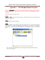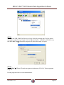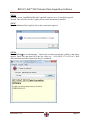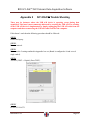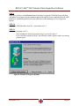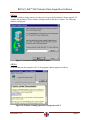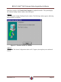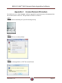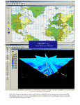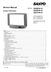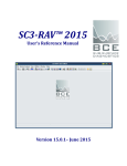
1
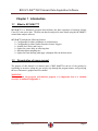
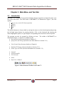
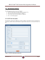
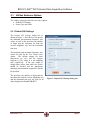
SC1-DAC™ 2015 User’s Reference Manual Version 15.0.1 – June 2015 . BCE SC1-DAC™ 2015 Seismic Data Acquisition Software BCE’s mission is to provide our clients around the world with state-of-the-art seismic data acquisition and analysis systems, which allow for better and faster diagnostics of the subsurface. The company provides state-of-the-art hardware and software solutions for a wide variety of seismic engineering applications. If necessary, we will customize our products to suit the requirements of our clients even better. BCE's products and services consist of Seismic Data Acquisition and Signal Conditioning Hardware Seismic Data Processing Software Applied Seismology Consulting Services Seismic Data Processing Professional Seminars By publishing this manual we will hopefully provide a better understanding of downhole seismic testing and the role it can play in geotechnical investigations. Baziw Consulting Engineers Ltd 3943 West 32nd Avenue Vancouver B.C. Canada V6S 1Z4 url: www.bcengineers.com email: [email protected] © 1998 - 2015 Baziw Consulting Engineers Ltd.. All rights reserved. The content on this work is protected by the copyrights of Baziw Consulting Engineers Ltd.. No part of this document may be reproduced, stored in a retrieval system, or transmitted in any form or by any means, electronic, mechanical, photocopying, or otherwise without the prior written permission of Baziw Consulting Engineers Ltd. Although every precaution has been taken in the preparation of this manual, we assume no responsibility for any errors or omissions, nor do we assume liability for damages resulting from the use of the information contained in this manual Revision 15.0.1 Page i BCE SC1-DAC™ 2015 Seismic Data Acquisition Software Automatic configuration of USB A/D to 8 Channel Single Ended Ability to apply noise suppression when utilizing a contact trigger Ability to apply notch filter on harmonics within the Cascadable Filters Enhanced display options when viewing seismic data Revision 15.0.1 Page ii BCE SC1-DAC™ 2015 Seismic Data Acquisition Software Table of Contents List of Figures ............................................................................................................................ iv Chapter 1 Introduction .......................................................................................................... 1 1.1 What is SC1-DAC™?.................................................................................................... 1 1.2 Organization of users manual......................................................................................... 1 Chapter 2 Main Menu and Tool Bar ...................................................................................... 2 2.1 Introduction ................................................................................................................... 2 2.2 File Submenu Options ................................................................................................... 3 2.2.1 SCPT Site Information .............................................................................................. 3 2.3 Utilities Submenu Options ............................................................................................. 4 2.3.1 Default GUI Settings ................................................................................................. 4 2.3.2 Sensor Type and Units ............................................................................................... 5 2.4 Window Submenu Options ............................................................................................ 5 2.5 Help Submenu Options .................................................................................................. 5 Chapter 3 Seismic Data Acquisition ...................................................................................... 6 3.1 Source Parameters and Data File Specification .............................................................. 6 3.2 A/D and Filter Parameters ............................................................................................. 7 3.3 Trigger Parameters ........................................................................................................ 9 3.4 Begin Acquisition, Stack Data, and Stop Acquisition Tool Bar ..................................... 10 Chapter 4 View Seismic Data ............................................................................................. 13 Chapter 5 Chart Formatting, Exporting, and Printing .......................................................... 16 Appendix 1 SC1-DAC™ Installation Procedure .................................................................... 17 Appendix 2 SC1-DAC™ Trouble Shooting ........................................................................... 20 Appendix 3 USB Flash Drive License Transfer Procedure ..................................................... 22 Appendix 4 License Removal Procedure ............................................................................... 29 Revision 15.0.1 Page iii BCE SC1-DAC™ 2015 Seismic Data Acquisition Software List of Figures Figure 1: Main Menu and Tool Bar in SC1-DAC™ .....................................................................2 Figure 2: SCPT Site Information dialog box ................................................................................3 Figure 3: Default GUI Settings dialog box...................................................................................4 Figure 4: Sensor Type and Units dialog boxes .............................................................................5 Figure 5: Data Acquisition dialog box .........................................................................................6 Figure 6: Default Directory Data dialog box ................................................................................7 Figure 7: A/D and Filter Parameters input screen .........................................................................8 Figure 8: Trigger Parameters input screen ...................................................................................9 Figure 9: Seismic Data display screen ....................................................................................... 10 Figure 10: Seismic Data Window Display Options dialog box ................................................... 11 Figure 11: Visual Reminder to Save Seismic Data ..................................................................... 11 Figure 12: File Save Dialog Box ............................................................................................... 12 Figure 13: Main graphical interface in View Seismic Data software option ............................... 13 Figure 14: Font dialog box ........................................................................................................ 14 Figure 15: Print dialog box ........................................................................................................ 14 Figure 16: Export dialog box ..................................................................................................... 14 Figure 17: Seismic trace in View Seismic Data software option ................................................. 15 Figure 18: Chart Editing dialog box .......................................................................................... 16 Figure 19: Chart Printing dialog box ......................................................................................... 16 Revision 15.0.1 Page iv BCE SC1-DAC™ 2015 Seismic Data Acquisition Software Chapter 1 Introduction 1.1 What is SC1-DAC™? SC1-DAC™ is a Windows® program that facilitates the data acquisition of uniaxial Seismic Cone (SC) time series data. The data can then be analyzed in more detail using the SC1-RAV™ seismic data analysis software. SC1-DAC™ includes the following features: Configurable for either geophones or accelerometers. Configurable for either contact Switch or Sensor Triggers. Suitable for P-Wave and S-wave. Option for a time delay in collecting data. Maximized data sampling rate. Option for Data Stacking (and apply a bandpass filter to the data stack). 1.2 Organization of users manual The purpose of this manual is to instruct users of SC1 -DAC™ in the use of the product by explaining its structure, taking the user step by step through the program menus, and specifying the use of interactive graphics and I/O routines. WARNING: To ensure that the program will function properly it is important that it is installed correctly as outlined in Appendix 1. Revision 15.0.1 Page 1 BCE SC1-DAC™ 2015 Seismic Data Acquisition Software Chapter 2 Main Menu and Tool Bar 2.1 Introduction SC1-DAC™ is a Windows® program that facilitates the data acquisition of uniaxial seismic cone (SC) time series data. The main menu of SC1-DAC™, as illustrated in Figure 1, has four options: File (to carry out the SC data acquisition Utilities Window. Help. The desired submenu is chosen either by moving the mouse over the desired option and pressing the left hand mouse button, by pressing function <F10> on the keyboard and selecting the desired highlighted option, or by pressing the corresponding menu item letter on the keyboard. The program can also be operated by clicking on icons. The toolbar of SC3-DAC™, as illustrated in Figure 1, consists of 10 different icons: Data Acquisition (for more details see Chapter 3) Specify Site and Testing Information (for more details see Section 2.2.1) View Seismic Data (for more details see Chapter 4) Default GUI Settings (for more details see Section 2.3.1) Sensor Type and Units (for more information see Section 2.3.2) Cascade Tile Horizontally Tile Vertically About Open User’s Manual Figure 1: Main Menu and Tool Bar in SC1-DAC™ Revision 15.0.1 Page 2 BCE SC1-DAC™ 2015 Seismic Data Acquisition Software 2.2 File Submenu Options The File option provides the user with 4 options: SCPT Site Information (for more details see Section 2.2.1) Data Acquisition (for more details see Chapter 3) View Seismic Data (for more details see Chapter 4) Exit – to close the program 2.2.1 SCPT Site Information The SCPT Site Information dialog box is shown in Figure 2 and allows the user to specify site information, which is then stored within the acquired seismic data file as well as the SC1DAC.ini file. Figure 2: SCPT Site Information dialog box Revision 15.0.1 Page 3 BCE SC1-DAC™ 2015 Seismic Data Acquisition Software 2.3 Utilities Submenu Options The Utilities option provides the user with 2 options Default GUI Settings Sensor Type and Units 2.3.1 Default GUI Settings The Default GUI Settings dialog box is shown in Figure 3. Here the user can specify the minimum and maximum frequency axis values, as well as the precision, the number of digits and the increment for both the vertical amplitude axis and the horizontal time axis. The minimum and maximum frequency axis values are used for the View Seismic Data option. The default settings for these frequencies are zero and the Nyquist frequency (1/2Δ, where Δ is the sampling rate) respectively. If the user wishes to change these values, then check box Enable should be checked and the appropriate minimum and maximum frequencies should be specified. The precision, the number of digits and the increment for both the vertical amplitude axis and the horizontal time axis are used for all charts displayed within SC1-DAC™. Revision 15.0.1 Figure 3: Default GUI Settings dialog box Page 4 BCE SC1-DAC™ 2015 Seismic Data Acquisition Software 2.3.2 Sensor Type and Units The Sensor Type and Units dialog boxes are shown in Figure 4. The Sensor Type Specification interface allows the user to specify whether Accelerometers (output proportional to particle acceleration) or Geophones (output proportional to particle velocity) are used for the downhole seismic testing (DST) investigation. The Desired Units user interface facilitates the specification of whether the particle velocities and accelerations recorded are given in units of m/s and m/s 2 or mm/s and mm/s2, respectively. Figure 4: Sensor Type and Units dialog boxes 2.4 Window Submenu Options The Window option provides the user with 4 options to arrange the open window(s): Cascade Tile Horizontally Tile Vertically Minimize All 2.5 Help Submenu Options The Help option provides the user with 3 options: About - provides software version information on SC1-DAC™. User’s Manual - opens the SC1-DAC™ user’s manual in a default pdf browser. Link to BCE - opens the Baziw Consulting Engineers’ web page in a default web browser. Revision 15.0.1 Page 5 BCE SC1-DAC™ 2015 Seismic Data Acquisition Software Chapter 3 Seismic Data Acquisition Selecting Data Acquisition under the File menu option or clicking on the Data Acquisition icon allows the user to carry out the data acquisition as well as to communicate with the BCE signal conditioning board and the analog/digital (A/D) conversion board. As shown in Figure 5, this dialog box has three tabs for data input: Source Parameters and Data File Specification. A/D and Filter Parameters. Figure 5: Data Acquisition dialog box Trigger Parameters. Once the data has been entered, the tool bar at the top of the screen is used to control the actual data acquisition. 3.1 Source Parameters and Data File Specification The Source Parameters and Data File Specification tab is illustrated in Figure 5 and the input parameters required on this tab are as follows: Radial Offset - radial offset (m) of the source from the penetration cone. Source Depth - depth (m) of the source into the ground. Probe Depth - cone depth (m) from ground level. Depth Increment – cone depth increment (m) between tests; by clicking on the adjacent arrow the probe depth will be increased by the depth increment. Save Data As - the user has the option to store seismic data in either ASCII or binary file formats by selecting the appropriate radio button. The default filenames are *.aci for ASCII file formats and *.bin for binary file formats. Binary file formats are desirable because they typically require less memory storage, while ASCII data files can easily be read into other programs. Data File Specification - the user can automate the seismic data file naming and saving process. A typical file name for a seismic file saved with the Automatic Specification check box enabled is outlined and defined as follows: Revision 15.0.1 Page 6 BCE SC1-DAC™ 2015 Seismic Data Acquisition Software SCPTS0_0R05_07_00 10-12-52 PM.aci SCPT S 0_0 R 05_07_00 10-12-52 PM .aci specified by the user in the Site Name edit box S-wave (S) or P-wave (P) - dominant source wave type probe depth specification right (R), left (L), or no (N) source polarization radio buttons day data acquired (i.e., day_month_year) time data acquired (i.e., hour-minute-second) user specified data type The default data file storage directory is selected by pressing the Directory List icon. Figure 6 illustrates the dialog box which appears when this icon is selected. The user browses the available drives and directories and selects the one most appropriate for seismic data file storage. The selected directory is then saved in the SC1DAC.ini file and becomes the default data file storage location. WARNING: When the program is first used the default directory is the folder where the program is stored. 3.2 Figure 6: Default Directory Data dialog box Time Delay - the user may not want to store early information within the seismic time series when conducting deep SC investigations. This is due to the fact that the source wave arrives much later in the time series and the early portion of the data contains no useful information. In this situation, the investigator should check the box entitled Enable and select the appropriate Time Delay with the accompanying slide bar. The Time Delay is specified as a percentage of the Sampling Time (see Section 3.2). If the Time Delay is Enabled, SC1-DAC™ will display the full seismic time series, but only store data which exceeds the user specified Time Delay. This saves significant data storage space on the computer hard drive. However, the implementation of a Time Delay is not all that important and is typically not implemented as most computer hard drives provide adequate storage space. A/D and Filter Parameters The A/D and Filter Parameters tab is shown in Figure 7. The A/D input parameters required on this tab are as follows: Data Gain - the data gain corresponds to the amplitude gain on the recorded data. The Data Gain can be set from 0 to 84 dB in 6 dB steps. While the data gain can be adjusted for different traces, it cannot be changed while stacking data: all traces that are stacked should be collected with the same gain. Revision 15.0.1 Page 7 BCE SC1-DAC™ 2015 Seismic Data Acquisition Software Sampling Rate - the sampling rate is specified in KHz and it ranges in values from 1 to 80 KHz, although for high signal resolution a sampling rate of at least 20 KHz is recommended. Once the user has specified the Sampling Rate, the program will Figure 7: A/D and Filter Parameters input screen determine the Actual Sampling Rate, which is a multiple of the specified Sampling Rate, to take optimal advantage of the fact that a digital trigger is used. Listed below are the options for the specified Sampling Rate with the associated Actual Sampling Rates: Specified Actual 1, 2, 4, 5, 50, 10, 20, 30, 150 40, 60, 80, 120 480 450 Sampling Rate (KHz) 90, 70, 140 100 420 400 110 130 440 390 It should be noted that the analog anti-aliasing filter is set automatically based on the specified sampling rate (at 1/3 of the sampling frequency). Sampling time - the sampling time is specified in ms and it corresponds to the total data acquisition time. For optimal data storage and processing, the sampling time should not be much longer than what is required to capture the P-wave and S-wave. For a first estimate of the required Sampling Time, the user should determine the maximum travel distance of the seismic wave and assume a wave velocity of 100 m/s to calculate the travel time. To determine the recommended Sampling Time the user should add to the travel time at least 60 ms to cover three periods of a 60Hz SH source wave. However, since data storage is not really limited in most cases, it is more important that the Sampling Time is set large enough to capture all required data within a vertical seismic profile than to optimize this parameter. Sensor Sensitivity - the user inputs the seismic sensor’s sensitivity allowing for the recording of the particle accelerations or velocities (in the true units of m/s 2 or m/s respectively). This value is provided by the SC system supplier. Revision 15.0.1 Page 8 BCE SC1-DAC™ 2015 Seismic Data Acquisition Software Apart from the A/D parameters this tab can also be used to set the bandpass filter parameters that are applied on the stacked data traces that are displayed. The P-wave Source Bandpass Filter Frequencies are applied if the Source Wave Type is specified as a P-wave, while the S-wave Source Bandpass Filter Frequencies are applied if the Source Wave Type is specified as a S-wave. 3.3 Trigger Parameters The Trigger Parameters tab is illustrated in Figure 8 and the five input parameters required for this tab are as follows: Trigger Type - there are two types of triggers: Contact Switch or Sensor. The Contact Switch is triggered when contact (i.e., ground) is made between source and receiver (e.g., when the source hammer strikes the truck pads). The Sensor option reflects a transducer type triggering mechanism Figure 8: Trigger Parameters input screen (e.g., Accelerometer or Geophone). Pretrigger - the Pretrigger slide bar allows the user to specify the amount of information to be stored prior to triggering. The pretrigger is specified as a percentage of the total Sampling Time. For example, if the total sampling time is 500 ms and the Pretrigger slide bar is set to 5% then the pretrigger is (500 x 0.05) = 25ms. The maximum allowable pretrigger is 30% of the total sampling time specified. If the user wants to store the Pretrigger seismic data the box entitled Save Pretrigger should be checked. Contact Trigger Parameters – if the user checks the box Enable Noise Suppression the program will apply an algorithm to suppress the noise in the trigger channel when using a contact trigger. Sensor Trigger Parameters – when using a sensor trigger the user can specify the gain on the trigger channel by selecting one of four possible settings 0 dB (1x), 20 dB (10x), 40 dB (100x) and 60 dB (1000x). The Trigger Level slide bar allows the user to specify the percentage of full scale trigger amplitude that signifies a trigger event. Revision 15.0.1 Page 9 BCE SC1-DAC™ 2015 Seismic Data Acquisition Software 3.4 Begin Acquisition, Stack Data, and Stop Acquisition Tool Bar Once the user has specified the necessary data acquisition parameters, seismic cone data acquisition can commence. The SC1-DAC™ tool bar options are as follows: Begin Acquisition - the Begin Acquisition option is chosen once the data acquisition parameters have been specified. At that time SC1-DAC™ stores the current data acquisition parameters in the SC1DAC.ini file (making these values the default parameters) and disables the user interface (with the exception of the Stop Acquisition button). As soon as the trigger has been set off, the Data Acquisition window as shown in Figure 9 opens to display the captured seismic data. WARNING: In case the windows do not appear side-by-side as shown below the Window option tile vertically can be used. The <F1> key can be used to toggle between the data acquisition and display windows to avoid the necessity of moving the mouse. Figure 9: Seismic Data display screen Revision 15.0.1 Page 10 BCE SC1-DAC™ 2015 Seismic Data Acquisition Software The recorded data will be displayed in the Acquired Seismic Data window with the last data set Figure 10: Seismic Data Window Display displayed in green at the top, the Options dialog box stacked trace (either filtered or unfiltered as determined by the user) in blue in the middle and the trigger channel in red at the bottom. The vertical light blue line shown in Figure 9 on the left of the screen signifies the trigger time. The user can determine which traces are shown by ticking the trace in the chart legend. The lay-out of the window can be changed with the options shown in Figure 10: o The Edit Chart Settings icon opens the dialog box shown in Figure 18, with which the chart settings can be changed; this option can also be used to export or print the chart. o The settings can be stored by clicking on the Save Chart Settings icon . o The user can also apply previously stored chart settings by clicking on the Load Chart Settings icon . o When the checkbox Left Axis Scales Automatic is ticked the scales are adjusted such that range displayed matches the amplitude of the waves. If this checkbox is left unticked the scales are set based on the specified data gain (as shown in Figure 5), which allows the user to optimize the gain setting without clipping the signal. WARNING: This option should only be used when the data gain is maxed out at 84 dB or to magnify the current trace under analysis. Otherwise the user may not recognize the low signal-to-noise ratio of the collected data sets. o When the checkbox Display Legend is ticked the chart legend is displayed on the right side of the chart. In the legend box the user can indicate which traces are to be displayed. Each part of the chart has a Crosshair and the coordinates of the intersection in the active area are shown at the bottom of the screen. Stop Acquisition - the user may abort the operation by pressing the Stop Acquisition push button. Upon the display of the latest seismic data set the Begin Acquisition and Stop Acquisition buttons are disabled until an appropriate Acquired Seismic Data option has been selected: Save Data If Save Data is selected the latest unfiltered (stacked) trace is saved. If the user were to inadvertently try to increase the depth, or change the polarization without saving the (stacked) trace a warning message as shown in Figure 11 is displayed, asking the user whether the Figure 11: Visual Reminder to Save Seismic Data Revision 15.0.1 Page 11 BCE SC1-DAC™ 2015 Seismic Data Acquisition Software data is to be saved. Intialize Stack / Stack Data The stack data option allows the user to stack multiple seismic traces at a specific depth by implementing repeated sources. Since the program automatically displays the average seismic data graph, this option generally results in a higher signal-to-noise ratio. To start the data stacking process Initialize Stack must be selected, upon which the bottom message panel will display the message that the trace has been stacked with the corresponding stack number (e.g., “'Data Acquisition Messaging: Seismic trace has been stacked '(now 1 sets in total”). For subsequent traces Stack Data must be selected to save the unfiltered stacked trace. After the stacked trace has been saved the data acquisition can be continued. If at that time changes are made to the Polarization, Depth or Depth Increment or either Automated Analysis is reset or the Source Wave Type re-specified, the stack number is reset and traces cleared from the Seismic Data Display screen. The data stacking process can be reset by selecting button “Reset Data Stack”. Delete Trace If Delete Trace is selected the last recorded trace is deleted. The application of a digital zero-phase bandpass frequency filter on the stacked traces (ST) is turned off and on by toggling button Apply Filter. A graphical LED at the top center of the SCPT Data Acquisition window shows at all times the status: Green ready to commence data acquisition Yellow waiting for trigger Red trigger occurred Once the data acquisition has been completed for a particular depth and/or polarity, the user may save the recorded trace by selecting the Save button. If the user has selected the Automatic Specification check box (as shown in Figure 5) then the seismic data file is automatically saved; otherwise the dialogue box for saving the captured seismic traces as shown in Figure 12 appears. Figure 12: File Save Dialog Box It should be noted that the data file includes the following header information: sample rate (ms), time delay (ms), probe depth, source radial offset, and source depth. Following the header and before the recorded data series the file contains the SCPT Site Information. Revision 15.0.1 Page 12 BCE SC1-DAC™ 2015 Seismic Data Acquisition Software Chapter 4 View Seismic Data The View Seismic Data option allows the user to analyze an individual seismic file. Analysis features consists of filtering the seismic trace, overlaying the unfiltered trace onto the filtered trace and displaying the smoothed Fourier transform of either the unfiltered or filtered seismic time series. Figure 13: Main graphical interface in View Seismic Data software option pon selecting this option an input dialog box appears where the user specifies the seismic file to process. Figure 13 shows the graphical output which appears once the appropriate seismic file has been selected. At the top of the window there is a row of buttons. The function of these buttons can be described as follows: Display Filtered: to display filtered traces (based upon Filter GUI parameter settings); Overlay Traces: to display unfiltered traces superimposed on the filtered traces; Filter GUI: to open the Cascadable Filters dialog box, which allows the user to specify the filter parameters; FFT Display: to display the frequency spectrums of either the filtered or unfiltered traces (depending on the Display Filtered setting); Display Pre-trigger: to display the pre-trigger data; Print Preview: to open the Print Preview dialog box (see Figure 15); Export Preview: to open the Export Preview dialog box (see Figure 16). Revision 15.0.1 Page 13 BCE SC1-DAC™ 2015 Seismic Data Acquisition Software Below the row of buttons there are various checkboxes and icons: The Edit Chart Settings icon opens the dialog box shown in Figure 18, with which the chart settings can be changed; this option can also be used to export or print the chart. The settings can be stored by clicking on the Save Chart Settings icon .. The user can also apply previously stored chart settings by clicking on the Load Chart Settings icon . The user can specify the chart title by entering it in the box and the chart title is displayed by checking the Show Title box. The chart title font can be changed by clicking on the Font icon , which opens a dialog box (see Figure 14). Figure 14: Font dialog box Figure 15: Print dialog box Figure 16: Export dialog box Figure 17a shows the graphical results after specifying a bandpass of 30 to 100 Hz. The user may then overlay the unfiltered seismic trace onto the filtered trace by selecting checkbox Overlay as illustrated in Figure 17b. The smoothed Fast Fourier Transform (FFT) of either the unfiltered or filtered seismic trace is derived and displayed by selecting checkbox FFT. The frequency spectrum of the filtered trace is displayed if the checkbox Filter is selected along with the FFT checkbox. Otherwise the unfiltered seismic trace’s frequency spectrum is displayed. Figure 17c illustrates the frequency spectrum of the filtered data file shown in Figure 17a. Finally in Figure 17d shows the filtered trace with the pre-trigger data displayed as well. Revision 15.0.1 Page 14 BCE SC1-DAC™ 2015 Seismic Data Acquisition Software Figure 17: Seismic trace in View Seismic Data software option A: filtered B: Overlaying unfiltered seismic time series onto filtered time series C:Frequency spectrum of seismic time series D:With pre-trigger data displayed Revision 15.0.1 Page 15 BCE SC1-DAC™ 2015 Seismic Data Acquisition Software Chapter 5 Chart Formatting, Exporting, and Printing The software contains a chart formatting, printing, and exporting utility. Figure 18 illustrates the graphical interface that appears when the chart formatting button is selected, which allows for extensive modification of the displayed data and chart attributes. In addition the data can be printed by selecting the Print tab, which brings up the Chart Printing Dialogue Box as shown in Figure 19. Finally, this utility has an extensive electronic Help function, which is accessed though the Help button at the bottom left of the screen. Figure 18: Chart Editing dialog box Figure 19: Chart Printing dialog box Revision 15.0.1 Page 16 BCE SC1-DAC™ 2015 Seismic Data Acquisition Software Appendix 1 SC1-DAC™ Installation Procedure In order for SC1-DAC™ to function properly it is important that the all software (incl. the InstaCal software) is installed in the right sequence. Therefore do not connect the USB-1208HS A/D device until step 3. The software should be installed as follows: STEP 1 Put SC1-DAC™ CD into CD reader; navigate to sub-directory InstaCal and install InstaCal (select file icalsetup.exe). STEP 2 After installation, reboot the computer. STEP 3 Plug USB-1208HS A/D into USB port and execute program InstaCal. InstaCal insures that the USB A/D device is recognized by the Windows® operating system and allows for configuration and calibration. Verify that the USB-1208HS device is configured as Board #0 as illustrated below. If not, select the USB-1208HS A/D device and right mouse click and select the Change Board # as shown below. Revision 15.0.1 Page 17 BCE SC1-DAC™ 2015 Seismic Data Acquisition Software STEP 4 Configure the USB-1208HS A/D device as Single Ended by selecting the Configure option shown above and selecting 8 Single Ended as illustrated below. It should be noted that every time SC1-DAC Pro™ is started the program will ensure this setting is in place STEP 5 Put SC1-DAC™ CD into CD reader; navigate to sub-directory SC3-DAC. Execute program setup.exe. Execute program sc1dac.exe as an Administrator. Revision 15.0.1 Page 18 BCE SC1-DAC™ 2015 Seismic Data Acquisition Software STEP 6 When the screen “InstallShield Wizard Completed” appears, leave “Launch the program” checked. This will allow for the CrypKey drivers to be automatically installed. STEP 7 Upon Installation of the CrypKey drivers the screen below appears. STEP 8 Run SC1-DAC™ as an administrator. On the first execution an interface similar to that below appears. Email (cut and paste) BCE the Site Code (e.g., “295A 9E3E 6774 4334 A8”). BCE email will then email the required Site Key for validation. Revision 15.0.1 Page 19 BCE SC1-DAC™ 2015 Seismic Data Acquisition Software Appendix 2 SC1-DAC™ Trouble Shooting There may be instances where the USB A/D device is reporting errors during data acquisition. This issue is most commonly addressed by resetting the USB A/D. The resetting of the USB A/D device is implemented by simply unplugging the USB A/D cable from the computer and then reconnecting the USB A/B cable back into the computer. If this doesn’t work then the following procedure should be followed: STEP 1 Reboot the laptop. STEP 2 Execute instacal. STEP 3 Make sure the 2 settings outlined in Appendix 1are set (Board is configured a #0 and set as 8 single ended). STEP 4 Test A/D (TEST -> Digital) (Press TEST). STEP 5 Re-run SC1-DAC™. Revision 15.0.1 Page 20 BCE SC1-DAC™ 2015 Seismic Data Acquisition Software Revision 15.0.1 Page 21 BCE SC1-DAC™ 2015 Seismic Data Acquisition Software Appendix 3 USB Flash Drive License Transfer Procedure This type of operation transfers a license from an existing authorized copy of an application on one computer to an unauthorized copy of the product on a second computer. The transfer process does not jeopardize your license in any way and is completely secure because the USB Flash Drive is registered to a specific PC in a specific location. This ensures the license can only be transferred to the target PC you specify. Please note where the software shows “floppy drive” a USB flash drive can be used as the medium instead. The procedure is illustrated by the transfer of the Calculator example program from PC-1 to PC2. STEP 1 Ensure that you have an authorized copy of the application on PC-1, an unauthorized copy of the application on PC-2, and a USB Flash Drive inserted into PC-2. STEP 2 Your first operation is on the unauthorized computer (i.e., PC-2).Start the program on PC-2. The program’s opening window is shown below: Figure 1: Unauthorized Program running on PC-2 Revision 15.0.1 Page 22 BCE SC1-DAC™ 2015 Seismic Data Acquisition Software STEP 3 In the above window, click the License option to display the Transfer in from another computer command, as shown in Figure 2 below; after that the system shows the window shown in Figure 3. Figure 2: “Transfer in…” Command Figure 3: “Transfer License In” Window (Step 1) Revision 15.0.1 Page 23 BCE SC1-DAC™ 2015 Seismic Data Acquisition Software STEP 4 In the above window, use the Browse button if necessary to supply the USB Flash Drive path, then click Next. The program imprints its registration on the USB Flash Drive and the system displays the following window: Figure 4: “Transfer License In” Window STEP 5 If you need to close the PC-2 program while you work with the PC-1 program, click the Continue Transfer Later button in the above window. The system displays the following popup message: Figure 5: Continue Transfer Later Popup Window STEP 6 Click OK to acknowledge the above popup. Revision 15.0.1 Page 24 BCE SC1-DAC™ 2015 Seismic Data Acquisition Software STEP 7 Remove the USB Flash Drive from PC 2, and insert it into PC 1. Start the program on PC 1, and when the BCE flash screen appears hit the space bar. This will open the License Configuration Manager; click the License button as shown below: Figure 6: Program on PC-1: “Transfer Out” Command STEP 8 In the above window, click the Transfer out to another computer option. The system displays the following window: Figure 7: “Transfer License Out” Window Revision 15.0.1 Page 25 BCE SC1-DAC™ 2015 Seismic Data Acquisition Software STEP 9 In the above window, use the Browse button if necessary to supply the USB Flash Drive path, then click Next. The program reads the registration imprint file and then writes a matching file to the USB Flash Drive, decrementing the license count at the source or discontinuing it (if it is a single user license). STEP 10 Remove the USB Flash Drive from PC-1, and return it to PC 2. STEP 11 Resume the program on PC-2. - If you did not exit from the program in Step 5, proceed to Step 13. - If you exited the program in Step 5, the following window appears when you start the program again: Figure 8: Transfer in Progress Window Revision 15.0.1 Page 26 BCE SC1-DAC™ 2015 Seismic Data Acquisition Software STEP 12 The above window simply advises you that you have previously initiated a license transfer. To continue this operation, click Continue existing transfer in the above window. The following window is displayed: Figure 9: Continue Pending Transfer Window STEP 13 If you did not exit the program on PC-2, the program window appears as follows: Figure 10: Window resuming operation of program on PC-2 Revision 15.0.1 Page 27 BCE SC1-DAC™ 2015 Seismic Data Acquisition Software In the above window, click Transfer Into Computer to complete the transfer. The system displays the Continue Pending Transfer window, shown in Figure9. STEP 14 Click Next in the Continue Pending Transfer window. The following window appears, indicating that the transfer is complete: Figure 11: “Transfer License In” Window STEP 15 Click Finish. The License Configuration window on PC-2 appears, showing that you are authorized to use it. Revision 15.0.1 Page 28 BCE SC1-DAC™ 2015 Seismic Data Acquisition Software Appendix 4 License Removal Procedure In certain cases (e.g. when obtaining a software upgrade) it may be necessary to demonstrate that the current license is removed. The procedure to do this is as follows: STEP 1 Execute software and then press 'space bar' during start-up. STEP2 Select Kill License as shown below. STEP 3 State Yes to message below to “kill” the current license. Revision 15.0.1 Page 29 BCE SC1-DAC™ 2015 Seismic Data Acquisition Software STEP 4 Email BCE the screen capture of confirmation code as shown below. Revision 15.0.1 Page 30