1
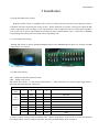
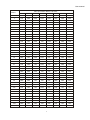
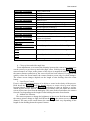
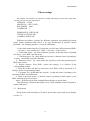
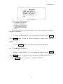
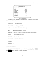
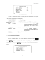
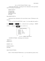
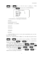
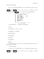
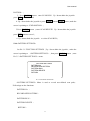
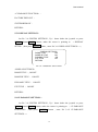
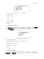
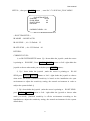
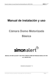
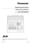
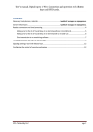
High Speed PTZ Camera User Manual User manual Foreword 1 Foreword.......................................................................................................................................................................... 2 Product overview ........................................................................................................................................................... 2 2.1 Product brief descriptions ............................................................................................................................. 2 2.2 Performance characteristics .......................................................................................................................... 2 2.3 Function explanation .......................................................................Ошибка! Закладка не определена.3 2.4 Technical patameters........................................................................................................................................ 3 3 Installation ..................................................................................................................................................................... 4 3.1 Speed dome DIP switch settings ......................................................................................................................... 4 3.1.1 Enter DIP switch settings ......................................................................................................................... 4 3.1.2 DIP switch settings .................................................................................................................................. 4 3.2 Speed dome installation .........................................................................Ошибка! Закладка не определена.6 3.2.1 Speed dome accessories ..............................................................Ошибка! Закладка не определена.6 4 Speed dome basic opration ............................................................................................................................................ 7 5 Menu settings............................................................................................................................................................... 10 5.1 Main menu ..................................................................................................................................................... 10 5.2 System information...........................................................................Ошибка! Закладка не определена.10 5.3 Address settings ................................................................................... Ошибка! Закладка не определена.11 5.4 Motion .............................................................................................. Ошибка! Закладка не определена.11 5.4.1 Set frame scan ........................................................................................................................................ 12 5.5 Pattern ....................................................................................................................................................... 16 5.5.1 Program pattern ..................................................................................................................................... 16 5.6 Camera setup memu ................................................................................................................................. 17 5.7 Cruise menu .........................................................................................Ошибка! Закладка не определена.17 5.8 Display setup .................................................................................................................................................... 18 5.9 Restore factory default.........................................................................Ошибка! Закладка не определена.18 5.9.1 Reboot system................................................................................................................................................ 18 6 Simple fault clearing and maintain ...................................................................................................................... 19 6.1 Simple fault clearing form ................................................................................................................................ 22 6.2 Notice ............................................................................................................................................................... 20 6.3 After service...................................................................................................................................................... 20 2 User manual 1 Foreword Before install and use high speed PTZ camera,please read below information carefully, 1.Before installation please read user manual carefully. 2.Please do not test and install the product on unstable flat,make sure the product place on a stable flat and assembly firmly before operation. 3. Prevent products damage caused by stress, severe vibration and immersion on transportation and storage. 4. Installation of this product must not be reversed;please handle with care,do not squeeze structural components,Otherwise, they may cause mechanical failure, affecting the overall performance.The transparent material on the speed dome iris is advanced optical materials,do not touch it,any scratches will affect image quality. 5. Prevent any foreign matter or liquid into camera,to avoid damage on camera. 6. When you make connection,please follow up safety standards,use with a dedicated power supply. RS-485 and video signal adopt TVS grade lightening protection technique,can effectively prevent damage caused by not more than 500W lighting,surging and other types of pulse signals.Please keep enough distance away from High-voltage equipment or cables when RS-485and video signal during transmission.Make lighting and surging protection measures when necessary. 7. Whether in use or non-use, never allow cameras aimed at the sun or other bright objects。Otherwise, may result in permanent damage of CCD . 8.Do not use it exceed the temperature, humidity standards. 9. This product do not have user repair parts。When camera has fault,please do not repairit,should find out fault refer to user manual,if can not find out reason,please send the camera to professional maintanence person. The maintenance person must be authorized by our company. 3 2 Product overview 2.1 Product brief description High speed PTZ camera adopt the latest scientific and technological achievements,best manufacturing technique,successful developed by years of valued experience,it is a high-performance digital signal processing (DSP) camera which equips with automatic zoom lens;build-in PTZ and digital decoders,representing a new generation of high-tech monitoring products. It uses all-digital control, simple and ingenious design, discretional quickly locate and continuous follow-up scan,it has automatic tracking function,make smart surverillance of all-round, non-blind spot,Can automatically adapt to the environment and target distance changes in light and dark, High reliability and long-term stable operation, without maintenance. High speed PTZ camera is compatible with a variety of control protocols,so it can support a variety of popular platforms.Match with other system,the connection use methods of different system is not the same,please contact the system manufacturer or distributors for necessary information. The various characteristics of the high speed PTZ camera , make it applicable to large-scale industries, active target object surveillance。Such as power systems, telecommunications sector, banking security, factories and enterprises, intelligent buildings, intelligent community, urban road monitoring, airports, stations and other monitoring occasions. 2.2 Performance characteristics 1. Build-in OSD English menu ,through menu to display and change the information and parameter of camera,can set and incoke presets、pattern scan、area scan and display areaetc. 2. Timing auto- activation function, Can set the ball machine idle for a period of time,then startarea scan, intermittent scan,continuous scan,pattern scan and invoke presets. 3. Integrated design, compact structure , high reliability. 4. 256 presets. 5. Adopt RS485 control. 6. Precision motor drive, running smoothly and responsive. 7. Horizontal 360°continuous rotation, no surveillance blind area. 8. Rotation speed automatic adjust according to lens’ zoom. 9. Veritial 90°,auto overturn 180°continuous surveillance. 10. Auto focus,auto white balance 11. Backlight compensation,you can see all the objects in a strong light enviroment. 12. Compatible with a variety of control protocol, baud rate adjustable. User manual 13. Wide Dynamic Camera Support(SONY1010、SONY490、SONY990) 4 Technical parameter Model ASD-36SO650IR200 Imaging source 1/3 sony CCD System PAL/NTSC Resolution 650TVL Effective pixel 752(H)ⅹ582(V) Min. illumination Color: 0.2 Lux/F1.6 (50 IRE) B&W :0.02 Lux/F1.6 (50 IRE) S/N ratio ≥60dB Backlight compesation ON/OFF White balance AUTO Electronic shutter 1/50sec ~ 1/120,000sec Focal length f=3.2 to 115.2mm Optical zoom 36X OPTICAL ZOOM.10X DIGITAL ZOOM Auto/manual , adopt continuous focus function Focus high-performance DSP,achieve Presets 256 Pattern scan 8 channels,each channel can record 100 action Cruise track 30 presets can join cruise,preset stay time can set Other scan Support horizontal scan,frame scan,radom scan Rotation range Horizontal 360°unlimited,vertical 180°,auto overturn Rotation speed Horizontal and vertical:min. 0.01°,max. 300°/s ( can auto adjust according to zoom times) Protocol PELCO D and PELCO P Menu Full screen menu Temperature control system Optional Power supply DC12V/4A Dimension 7 inch Operation condition Material all-digital -10℃~+70℃(Optional temperature control components), 95%RH Aluminum shell, waterproof ratingIP66 3 ﹤ User manual 3 Installation 3.1 Speed dome DIP switch settings High speed dome camera is compatible with a variety of control protocols, baud rate can be adjusted to make it compatible with more monitoring and control system。Before install the speed dome camera,please adjust the DIP switch to appropriate code according to your requirements,in order to adjust the baud rate,control protocol,address code. If there are no special requirements,the speed dome factory default address code is 1,baud rate is 2400BPS corresponding code,control protocol is PELCO-D corresponding code. 3.1.1 Enter DIP switch settings Through DIP switch to change BAUD-RATE,PROTOCOL and ADDRESS.Speed dome core, housing and DIP switch pictures see as below: Pic 1. DIP cover Pic 2.DIP Switch 3.1.2 DIP switch settings SW1:Baud rate and control protocol switch SW2:Address code switch DIP switch “ON” means “1”,DIP switch “OFF”means“0”, DIP switch left is low position ,right is high position Baud rate and control protocol setting form: SW1 Code point Control protocol Baud rate 1 2 3 4 OFF OFF PELCO-P ON OFF PELCO-D OFF ON Reservation ON ON Reservation OFF OFF AUTO ON OFF 2400 OFF ON 4800 ON ON 9600 2. SW2 is used for setting speed dome address code。Address adopt binary mode,you can set at total 256 different speed dome address code, see address code table. The factory default settings shown in Figure 2. 4 User manual Address SW2 speed dome address code table 1 2 3 4 5 6 7 8 0 OFF OFF OFF OFF OFF OFF OFF OFF 1 ON OFF OFF OFF OFF OFF OFF OFF 2 OFF ON OFF OFF OFF OFF OFF OFF 3 ON ON OFF OFF OFF OFF OFF OFF 4 OFF OFF ON OFF OFF OFF OFF OFF 5 ON OFF ON OFF OFF OFF OFF OFF 6 OFF ON ON OFF OFF OFF OFF OFF 7 ON ON ON OFF OFF OFF OFF OFF 8 OFF OFF OFF ON OFF OFF OFF OFF 9 ON OFF OFF ON OFF OFF OFF OFF 10 OFF ON OFF ON OFF OFF OFF OFF 11 ON ON OFF ON OFF OFF OFF OFF 12 OFF OFF ON ON OFF OFF OFF OFF 13 ON OFF ON ON OFF OFF OFF OFF 14 OFF ON ON ON OFF OFF OFF OFF 15 ON ON ON ON OFF OFF OFF OFF 16 OFF OFF OFF OFF ON OFF OFF OFF 17 ON OFF OFF OFF ON OFF OFF OFF 18 OFF ON OFF OFF ON OFF OFF OFF 19 ON ON OFF OFF ON OFF OFF OFF 20 OFF OFF ON OFF ON OFF OFF OFF 21 ON OFF ON OFF ON OFF OFF OFF 22 OFF ON ON OFF ON OFF OFF OFF 23 ON ON ON OFF ON OFF OFF OFF 24 OFF OFF OFF ON ON OFF OFF OFF 25 ON OFF OFF ON ON OFF OFF OFF 26 OFF ON OFF ON ON OFF OFF OFF 27 ON ON OFF ON ON OFF OFF OFF 28 OFF OFF ON ON ON OFF OFF OFF 246 OFF ON ON OFF ON ON ON ON 247 ON ON ON OFF ON ON ON ON 248 OFF OFF OFF ON ON ON ON ON 249 ON OFF OFF ON ON ON ON ON 250 OFF ON OFF ON ON ON ON ON 251 ON ON OFF ON ON ON ON ON 252 OFF OFF ON ON ON ON ON ON 253 ON OFF ON ON ON ON ON ON 254 OFF ON ON ON ON ON ON ON 255 ON ON ON ON ON ON ON ON 5 User manual 3.2 Speed dome camera installation 3.2.1 Speed dome install accessories dimension Product Pic 3-1 Pic 3-1 Bracket size Pic 3-2 Pic 3-2 6 User manual 3.2.2 Speed dome camera installation Step 1 :Bracket installationq Pic 3-3 Determine the location of the mounting screw holes Pic 3-4 Drill holes in the installation Pic 3-5 Drill holes as required Pic 3-6 Tighten the screws Be installed in the walls of the ball machine to determine the installation location, according to the screw hole bracket on the wall with a signal pen draw hole,See Pic 3-3。Drill the hole as Pic 3-4。The expansion of the screw into the hole; the cable through the bracket, align the screw holes on the bracket and then tighten the nut on the screw, As Pic 3-6。 Step 2 :Installation of the ball machine 3 on the bracket screws loose, align the ball machine frame blank into the head cover and tighten the bracket screws on the three to prevent the ball machine off. 7 User manual 4 The basic operation of the speed dome camera Since different platforms of concrete operation methods are not identical, Generally, should be based on the system manufacturer's operating manual prevail under different circumstances will have special requirements and methods of the operation, please contact the dealer to obtain the necessary information.Here only Introduced the keyboard how to control the ball machine method. 1.Power On Self Test After the speed dome camera power on, the camera process the horizontal and vertical movement by auto, Through the self-test to determine speed dome camera work fine. Control the camera rotation from top to bottom ,right to left: After selected one camera, you can manually control the speed dome camera top to bottom,right to left by the joystick .The joystick control the movement of the camera, when the joystick shake to the right, the camera is also to right. Similarly, when the joystick to the left , camera same too. 2. Preset setting According to the following steps to set preset : (1) select the camera (more information please read control of the keyboard manual); (2) operation joystick, zoom button, focus button, buttons adjust the camera aperture screen; (3) Press the number key +PRESET (Enter the specified preset ), save the preset scene parameters. 3. Call preset Follow the below step to watch the preset: (1)select the camera; (2) Press the number key +PREVIEW (enter the designated preset ), the camera move to the preset position immediately, the lens zoom, focus and aperture is also automatically change to the preset parameters; if the input is a special function of the preset (see "Preset function menu"), the speed dome camera will perform with special features preset of the corresponding functions (such as: Enter the 80 preset, the camera auto-tracking feature). Preset function list Special preset INVOKE 64/95 PRESET INVOKE 57 PRESET INVOKE 56 PRESET/IRISINVOKE 97/99 PRESET INVOKE 96 PRESET OR OTHER PTZ CONTROL Specific of function Enter the ball machine menu Enter CAMERA menu Forced to exit Start Auto Scan Off Auto Scan 8 menu User manual INVOKE 32 PRESET INVOKE 53 PRESET INVOKE 49 PRESET INVOKE 50 PRESET INVOKE 58 PRESET SET 51 PRESET SET 52 PRESET INVOKE 51 PRESET INVOKE 52 PRESET INVOKE 93 PRESET INVOKE 94 PRESET INVOKE 59 PRESET INVOKE 100 PRESET OR 1+F1 INVOKE 101 PRESET OR 2+F1 1+F2 2+F2 INVOKE 106 PRESET Call 1 pattern scan Call 2 pattern scan Call 3 pattern scan Call 4 pattern scan Pattern scan 1 Set the right / left scanning 1 as beging Set the right / left scanning 1 as Ending Invoke right/left scanning 1 Invoke right/left scanning 2 System restart Restore the factory parameters starts four combination functions (parades preset points to 64 points) Manually open the first set of infrared light Manually open the second set of infrared light Manually close the first set of infrared light Manually close the second set of infrared light Infrared light automatically open mode 4.Close-up lens and wide-angle lens Zoom adjustment, or to narrow the disparity between the camera lens, zoom in or out the scenery to get close-up and wide-angle effect. Hold down the ZOOM+ , the camera features are closer to the picture of the object is magnified; hold the ZOOM- , the camera features pulled away, the screen object has been reduced. If you press and quickly release the zoom button, the camera monitor screen only for small changes. The camera zoom changes depends on the length of time holding down the zoom button. 5.Lens Focus Control Focus is adjustable camera images of an object or scene in the clarity of the process. Hold down the FOCUS+ from the distant objects or scenes clear up near objects become blurred. Hold down the FOCUS-, proximity to clear up objects or scenes, distant objects become blurred. Focus button repeatedly until you adjust the monitor screen objects into clear from the ambiguity. The same as the zoom button, the camera focused vary depending on the length of time holding down the focus button. 6.Manual Iris Function The camera aperture to change the brightness of the screen. Hold down the IRIS+ , the camera picture change to light, hold down the IRIS- , the camera screen change to dimmed. The same as the zoom button, the camera light dark vary depending on the length of time holding down the aperture button. 9 User manual 5 Menu settings This chapter will introduce the operation of OSD menu.Plug in power,after speed dome self-test,you will see below information: VERSION:V10.04 PROTOCOL:PELCO-P/D BAUD RATE:2400 CAMERA ID:1 HORIZONTAL CHECK OK VERTICAL CHECK OK CAMERA CHECK OK Different surveillance systems has different operation ways,detailed operation please contact distributor.Here below is an easy introduction of NQJ302 control keyboard(our company product)to operate OSD menu. 1.Enter main menu:setup No.95 preset,and you will enter OSD main menu.IRIS+ (iris open)is the confirm key,IRIS-(iris close)is the exit key. 2.Enter other menu:Up / down shake the joystick, so that the cursor is pointing to a menu,press IRIS+enter the menu. 3.Function select:Up / down shake the joystick, so that the cursor is pointing to a menu,press IRIS+select this function. 4.Parameter select:Up / down shake the joystick to select the parameter,press IRIS+,then restore. 5.Restore settings:Press IRIS+ ,restore the settings,it is effective if has corresponding prompt. 6.Does not restore and back to last menu: press IRIS- back to last menu, it is effective if has corresponding prompt. 7.Exit menu: Up / down shake the joystick,so that the cursor is pointing to exit option,press IRIS+exit OSD menu. 8.Back to previous menu:so that the cursor is pointing to back option,press IRIS+ and back to previous menu. Notes:Different speed dome setting,different display on speed dome. The following is detailed description of use smart standard control keyboard to oprate OSD menu: 5.1 Main menu Speed dome work normally,set No.64/95 preset,enter main menu,screen display is as Pic 3.1. 10 User manual MAIN MENU CAMERA SETTINGS--- > DOME SETTINGS ---> FUNCTION SETTINGS--- > SYSTEM SETTINGS ---> SPECIAL FUNCTION--- > EXIT Pic 3.1 MAIN MENU Main menu contents despription: < CAMERA SETTINGS > < DOME SETTINGS > < FUNCTION SETTINGS > < SYSTEM SETTINGS > < SPECIAL FUNCTION > <EXIT> To enter the menu and the implementation of the various functions of the basic operation is as follows: 1.On Pic 3.1 MAIN MENU,Up / down shake the joystick or Press ZOOM+ button/ZOOM- button,so that the cursor is pointing to a menu item or function option; 2.Press FOCUS+ button,enter menu or operate a function option. 5.2 < CAMERA SETTINGS > On Pic 3.1 MAIN MENU,Up / down shake the joystick or Press ZOOM+ button/ZOOM- button,so that the cursor is pointing to CAMERA SETTINGS--->, then press FOCUS+ button,Enter Pic 3.2 CAMERA SETTINGS 11 User manual CAMERA SETUP LANGUAGE ENGLISH ZOOMDISP ON AGC 200 BLC OFF SHUTTER AUTO FOCUS AUTO BRIGHT 130 COLORSEL AUTO MIRROR OFF LENINIT ---DEFAULT ---- Pic 3.2 CAMERA SETUP CAMERA SETUP: checking the basic information of the speed dome camera. Followings are the functions: LANGUAGE: ENGLISH/Chinese ZOOMDISP:zoom display,ON/OFF AGC :Auto Gain,200(160---240/Auto) BLC :Backlight compensation,ON/OFF SHUTTER : AUTO---(1/50,1/120,1/250,1/500,1/1000,1/2000--1/10000) FOCUS : AUTO/MANU/KEYAUTO BRIGHT : 130(60---170)。 COLORSEL: AUTO/BLACK/COLOR LENINIT : DEFAULT : 5.3 <DOME SETTINGS> On Pic 3.1 MAIN MENU,Up / down shake the joystick or Press ZOOM+ button/ZOOM- button,so that the cursor is pointing to DOME SETTINGS--->,then press FOCUS+ button,Enter Pic 3.3 DOME SETTINGS 12 User manual DOME SETTINGS AUTO INVERT IDLE TIME/MIN IDLE ACTIVE ACTIVE No. REBOO TRUN RUN No. RETURN ON 0 NO NO Pic 3.3 DOME SETTINGS On Pic 3.3 DOME SETTINGS,checking the basic information of the speed dome camera. Followings are the functions: DOME SETTINGS AUTO INVERT IDLE TIME/MIN function close IDLE ACTIVE ACTIVE No. REBOOT RUN RUN No. RETURN //Dome Setting //Auto flip ON/OFF // Idle time (minutes):0~255,为 0 hoursIdle time // Free activation:NO/PRESET/SCAN/PATT ERN/TOUR--- No / preset / scan / pattern / cruise // Air free activation number // Restart function : NO/PRESET/SCAN/PATTERN/TOU R/LAST STA--// Restart function number //Return 5.4 < FUNCTION SETTINGS > On Pic 3.1MAIN MENU,Up / down shake the joystick or Press ZOOM+ button/ZOOM- button , so that the cursor is pointing to FUNCTION SETTINGS--->,then press FOCUS+ button enter Pic 3.4< FUNCTION SETTINGS > memu FUNCTION SETTINGS PRESET SETUP ---> TOUR SETUP---> SCAN SETUP---> PATTERN SETUP---> RETURN 13 User manual Pic 3.4< FUNCTION SETTINGS > Menu <FUNCTION SETTINGS> checking the basic information of the speed dome camera. Followings are the functions: <PRESET SETUP> <TOUR SETUP> <SCAN SETUP> <PATTERN SETUP> RETURN 5.4.1<PRESET SETUP> checking the basic information of the speed dome camera. Followings are the functions: On Pic 3.4< FUNCTION SETTINGS > memu,Up / down shake the joystick or Press ZOOM+ button/ZOOM- button,so that the cursor is pointing to PRESET SETUP--->;then press FOCUS+ button,See Pic 3.4.1: PRESET SETTINGS PRESET No. 1 PRESET SET PRESET CALL PRESET DELETE RETURN Pic 3.4.1 <PRESET SETTINGS > < PRESET SETTINGS > Followings are the functions: PRESET No.: PRESET SET: PRESET CALL: PRESET DELETE: RETURN 5.4.2<TOUR SETTINGS> On Pic 3.4 FUNCTION SETTINGS menu,Up / down shake the joystick or Press 14 User manual ZOOM+ button/ZOOM- button , so that the cursor is pointing to TOUR SETTINGS---> then press FOCUS+ button,enter Pic 3.4.2 TOUR SETTING。 TOUR SETTINGS TOUR No. 1 STAY DELAY 4 TOUR SPEED 63 TOUR SET TOUR RUN TOUR DEL RETURN Pic 3.4.2< TOUR SETTINGS >Menu < TOUR SETTINGS > Followings are the functions: TOUR No.: STAY DELAY:(S):0~255 TOUR SPEED::0~63 SPEED TOUR SET: TOUR RUN: TOUR DEL: RETURN: <TOUR SETTING>is used to set the camera automatically preset scan line. Followings are the functions: On Pic 3.4.2< TOUR SETTINGS > Menu,Up / down shake the joystick or Press ZOOM+ button/ZOOM- button,so that the cursor is pointing to STAY DELAY [(S)0~255S],then press FOCUS+ button/FOCUS- button,Left / right shake the joystick, select the residence time 2.After,Up / down rocker rocking or press ZOOM+button/ZOOM-button, make the cursor is pointing to TOUR SET,Press FOCUS+ buton enter,you will see1~16 number preset,Left / right shake the joystick select No.1 Preset press IRIS+ button to saved,then it will auto to return to Pic 3.4.2,2~16 number preset will be same setting。Cruise preset positioncan press ZOOM+ button ZOOM- button to revised,after revised then press IRIS+ button to saved. 3.after,Up / down shake the joystick or press ZOOM+ button/ZOOM- button, make the cursor is pointing to TOUR RUN. 15 User manual 5.4.3<SCAN SETTINGS> On Pic 3.4 FUNCTION SETTINGS,Up / down shake the joystick or Press ZOOM+ button/ZOOM- button , so that the cursor is pointing to SCAN SETTINGS,then press FOCUS+button,enter Pic 3.4.3 Scan Setting Function。 SCAN SETTINGS SCAN No. 1 SCAN MODE <180 SCAN SPEED 55 START POSTION END POSTION SCAN RUN SCAN DELETE RETURN Pic 3.4.3 SCAN SETTINGS < SCAN SETTINGS > 。Followings are the functions: SCAN No.: SCAN MODE:(>180°or <180°) SCAN SPEED::0~63 SPEED START POSTION: END POSTION: SCAN RUN: SCAN DELETE: RETURN: < SCAN SETTINGS > is used to set the camera automatically preset scan line. Followings are the functions: 1.Select Scan number; 2.On Pic 3.4.3 SCAN SETTINGS,Up / down shake the joystick or Press ZOOM+ button/ZOOM- button , so that the cursor is pointing to <START 16 User manual POSTION>; 3.Press FOCUS+ button,enter SCAN RUN,Up / down shake the joystick, press IRIS+button to saved; 4. Up / down shake the joystick or press ZOOM+button/ZOOM- button,make the cursor is pointing to <END POSTION>; 5.Press FOCUS+ button,eneter SCAN DELETE,Up / down shake the joystick, press IRIS+button to saved; 6. Up / down shake the joystick to select SCAN RUN。 5.4.4<PATTERN SETTINGS> On Pic 3.1 FUNCTION SETTINGS,Up / down shake the joystick,make the cursor is pointing to <PATTERN SETTINGS >,then press FOCUS+ button,enter Pic 3.5 <PATTERN SETTINGS > menu. PATTERN SETTINGS PATTERN No. RECORD NEW PATTERN PATTERN RUN PATTERN DELETE RETURN Pic 3.5<PATTERN SETTINGS> <PATTERN SETTINGS> Menu is used to record user-defined scan path。 Followings are the functions: PATTERN No.: RECORD NEW PATTERN: PATTERN RUN: PATTERN DELETE: RETURN: 17 User manual Pattern scan is used to set and clear pattern scan line. PATTERN No:Select PATTERN No。PATTERN No range 1~4。See as following: 1.On Pic 3.5<PATTERN SETTINGS >,Up / down shake the joystick,make the cursor is pointing to PATTERN NO.; 2.Up / down shake the joystick or press ZOOM+ button/ZOOM- button,make the cursor is pointing to < RECORD NEW PATTERN > press FOCUS+ button; enter PATTERN RUN. 3.Up / down shake the joystick or press ZOOM+ button/ZOOM- button, RECORD NEW PATTERN 4.Up / down shake the joystick or press ZOOM+ button/ZOOM- button, make the cursor is pointing to < PATTERN RUN > press FOCUS+ button,PATTERN RUN; 5.5 SYSTEM SETTINGS On Pic 3.1MAIN MENU,Up / down shake the joystick or press ZOOM+ button/ZOOM- button, make the cursor is pointing to SYSTEM SETTINGS--->, then press FOCUS+ button,enter Pic 3.6 SYSTEM SETTINGS SYSTEM SETTINGS SYSTEM INFORMATION DISPLAY SETUP---> CLEARANCE FUNCTION---> FACTORY DEFAULT SYSTEM REBOOT RETURN Pic 3.6 SYSTEM SETTINGS < SYSTEM SETTINGS >: SYSTEM INFORMATION: <DISPLAY SETUP>: 18 User manual <CLEARANCE FUNCTION>: FACTORY DEFAULT: SYSTEM REBOOT: RETURN: 5.5.1 DISPLAY SETTINGS : On Pic 3.6 SYSTEM SETTINGS,Up / down shake the joystick or press ZOOM+ button/ZOOM- button, make the cursor is pointing to < DISPLAY SETUP>,then press FOCUS+ button,enter Pic 3.6.1 DISPLAY SETTINGS--->。 DISPLAY SETTINGS DOME TITLE ON DOME ID TITLE ON DYNAMIC TITLE ON PTZ TITLE ON RETURN Pic 3.6.1 DISPLAY SETTINGS <DISPLAY SETTINGS> DOME TITLE:,ON/OFF DOME ID TITLE: ON/OFF DYNAMIC TITLE: ON/OFF PTZ TITLE: ON/OFF RETURN: 5.6 CLEARANCE SETTINGS : On Pic 3.6 SYSTEM SETTINGS,Up / down shake the joystick or press ZOOM+ button/ZOOM- button, make the cursor is pointing to < CLEARANCE FUNCTION> , then press FOCUS+ button , enter Pic 3.6.2 CLEARANCE SETTINGS---> 19 User manual CLEARANCE SETTINGS CLEAR PRESET CLEAR SCAN CLEAR TOUR CLEAR PATTERN RETURN Pic 3.6.2 CLEARANCE SETTINGS <CLEARANCE SETTINGS>: CLEAR PRESET: CLEAR SCAN: CLEAR TOUR: CLEAR PATTERN: RETURN: 5.7 SPECIAL_FUNC MENU : On Pic 3.1MAIN MENU,Up / down shake the joystick or press ZOOM+ button/ZOOM- button, make the cursor is pointing to < SPECIAL FUNCTION >, then press FOCUS+ button,enter Pic 3.7 SPECIAL_FUNC MENU SPECIAL_FUNC MENU IR SYSTEM SETUP---> MOTION DETEC WDR LEVEL RETURN Pic 3.7 SPECIAL_FUNC MENU <SPECIAL_FUNC MENU>: IR SYSTEM SETUP:Didn’t come with this setting now MOTION DETEC:ON/OFF WDR LEVEL:,OF/OFF RETURN: 5.7.1 IR SYSTEM SETUP On Pic 3.7 SPECIAL_FUNC MENU,Up / down shake the joystick or press ZOOM+ button/ZOOM- button, make the cursor is pointing to < IR SYSTEN 20 User manual SETUP>,then press FOCUS+button ,enter Pic 3.7.1 SPECIAL_FUNC MENU IR SYSTEM SETUP IR MODE AUTO IR ON SENS 25 IR OFF SENS 80 RETURN CURRENT LEVEL:XX Pic 3.7.1 IR SYSTEN SETUP < IR SYTEM SETUP > IR MODE:ON/OFF/AUTO IR ON SENS:,10~50 Default IR OFF SENS:,60~255 Default 25 80 RETURN: CURRENT LEVEL: 1、on IR SYSTEM SETUP menu,Up / down shake the joystick,make the cursor is pointing to IR MODE,Press FOCUS+/FOCUS+ button or Left / right shake the joystick to choose what mode you need,then press FOCUS+ button。 2、Up / down shake the joystick,make the cursor is pointing to IR ON SENS,press FOCUS+/FOCUS+ button or Left / right shake the joystick to choose what mode you need。(Infrared sensitivity is based on the installation site open environment to adjust the sensitivity setting, the normal environment in order to subject the system default)。 3、Up / down shake the joystick,make the cursor is pointing to IR OFF SENS, press FOCUS+/FOCUS+ button or Left / right shake the joystick to choose what mode you need 。( Infrared sensitivity is off-site environment according to the installation to adjust the sensitivity setting, the normal environment for the system default date). 21 User manual 6 Easy troubleshooting and maintenance 6.1 Easy troubleshooting list Error reports Problem connect the wrong power cable Power supply is damaged No movement after Protective tube is power on,no image damaged Power cable connect not good the ball machine address Self test and with coding, control protocol, image after power baud rate is wrong on but can not RS-485 cable connect control wrong Video cable connect not The image good unstable Power is not enough RS-485 cable connect not good Can control but not One of the RS-485 cable broken Solution Correct Replacement Replacement Eliminate re-set the ball machine address coding, control protocol, baud rate Check RS-485 connect cable Eliminate Replacement Check RS-485 connect cable Check RS-485 connect cable 6.2 Notes 1. Careful Transport Transport, storage and installation process, we need to prevent stress, severe vibration and damage to the product immersion. 2. Do not demolish unauthorized Camera Do not remove screws or protective cover, there is no repair parts machine. The work should by qualified maintenance people to do it. 3. Be careful installation of the movement To be especially careful, light up-light down, do not force squeezing movement and the structural components, so as to avoid the ball machine trouble. For security reason, do not cover the ball is not installed electricity. 4. Power, video lines and control lines 22 User manual Power lines, video lines and control lines preferable to use shielded cable and is independent of routing, can not blend together with other lines. 5. Electrical Safety In use must comply with all electrical safety standards, the ball machine or signal transmission line should work with high-voltage equipment or cables to maintain a sufficient distance (at least 50 meters), if necessary, do a good job against lightning, surge and other protective measures. 6. Cleaning When cleaning the camera housing, please use the dry soft cloth. such as severe dirt, please use neutral cleaner gently wipe. Do not use strong or with abrasive cleaner, so as not to scratch jacket, affecting image quality. 7. Please strictly sealed to prevent liquid splashing into the ball machine, otherwise it will result in permanent damage to the device. 8. Do not use the camera when exceed the limits of temperature, humidity. Ball machine use temperature of -25 ℃ to 70 ℃, humidity less than 90%. 9. Do not install the camera near the air-conditioned outlet. Under such conditions, the lens would be fogging following the state of hydrometeor By the opening and closing air-conditioner frequently caused the high and low temperature changed. By the opening and closing door frequently caused the high and low temperature changed. Make the glasses fogging environment. In a room filled with smoke or dust . Do not use the camera toward strong light for long time, such as the sun.. Spotlight and other light will cause screen aging. Use the camera toward to strong light for a long time, may be rised CCD of the color filter damage and loss the ture color images. 6.3 Service Dear users, in order to ensure the full enjoyment of your services, please read the following products and services charter. (一)our company supply the speed dome camera of limited warranty and lifetime maintenance services 1. The warranty period from the date of sale for 12 months, in the warranty period, you will enjoy the product free service, delivered or sent by the user (improper use,man-made causes of failure or an irresistible fault do not belong to the scope of the warranty). 2. After 12 month limited free repairing duration,the products will absorb life time repair with payable services.。 (二)Speed dome camera repair time. 1.Since the customer send the product to 24-hour service. 23 User manual 1. 2. Please advise the related contact first, then return the product to our company. Otherwise, the product not timely maintenance 24