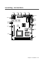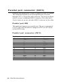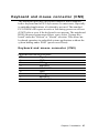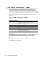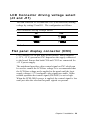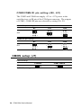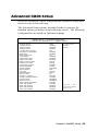
1
PCM-5894
PCM-5894C
All-in-One Single Board Pentium
Computer with SVGA, Ethernet
and 4 serial ports
FCC STATEMENT
THIS DEVICE COMPLIES WITH PART 15 FCC RULES.
OPERATION IS SUBJECT TO THE FOLLOWING TWO
CONDITIONS: (1) THIS DEVICE MAY NOT CAUSE HARMFUL INTERFERENCE. (2) THIS DEVICE MUST ACCEPT
ANY INTERFERENCE RECEIVED INCLUDING INTERFERENCE THAT MAY CAUSE UNDESIRED OPERATION.
THIS EQUIPMENT HAS BEEN TESTED AND FOUND
TO COMPLY WITH THE LIMITS FOR A CLASS "A"
DIGITAL DEVICE, PURSUANT TO PART 15 OF THE FCC
RULES. THESE LIMITS ARE DESIGNED TO PROVIDE
REASONABLE PROTECTION AGAINTST HARMFUL
INTERFERENCE WHEN THE EQUIPMENT IS OPERATED
IN A COMMERCIAL ENVIRONMENT. THIS EQUIPMENT GENERATES, USES, AND CAN RADIATE RADIO
FREQENCY ENERGY AND , IF NOT INSTATLLED AND
USED IN ACCORDANCE WITH THE INSTRUCTION
MANUAL, MAY CAUSE HARMFUL INTERFERENCE TO
RADIO COMMUNICATIONS. OPERATION OF THIS
EQUIPMENT IN A RESIDENTIAL AREA IS LIKELY TO
CAUSE HARMFUL INTERFERENCE IN WHICH CASE
THE USER WILL BE REQUIRED TO CORRECT THE
INTERFERENCE AT HIS OWN EXPENSE.
Copyright Notice
This document is copyrighted, 1997. All rights are reserved. The
original manufacturer reserves the right to make improvements to
the products described in this manual at any time without notice.
No part of this manual may be reproduced, copied, translated or
transmitted in any form or by any means without the prior written
permission of the original manufacturer. Information provided in
this manual is intended to be accurate and reliable. However, the
original manufacturer assumes no responsibility for its use, nor
for any infringements upon the rights of third parties which may
result from its use.
Acknowledgements
AMD is a trademark of Advanced Micro Devices, Inc.
AMI is a trademark of American Megatrends, Inc.
Award is a trademark of Award Software International, Inc.
Cyrix is a trademark of Cyrix Corporation.
IBM, PC/AT, PS/2 and VGA are trademarks of International
Business Machines Corporation.
Intel and Pentium are trademarks of Intel Corporation.
Microsoft Windows ® is a registered trademark of Microsoft
Corp.
SMC is a trademark of Standard Microsystems Corporation.
RTL is a trademark of Realtek Semi-Conductor Co., Ltd.
C&T is a trademark of Chips and Technologies, Inc.
UMC is a trademark of United Microelectronics Corporation.
ITE is a trademark of Integrated Technology Express, INC.
SIS is a trademark of Slicon Integrated Systems Corp.
VIA is a trademark of VIA Technology, Inc.
All other product names or trademarks are properties of their
respective owners.
Part No. 2006589400 Manual PCM-5894 1st Edition
Printed in Taiwan November 1997
Packing list
Before you begin installing your card, please make sure that the
following materials have been shipped:
• 1 PCM-5894/PCM-5894C All-in-One Single Board Computer
• 1 User's Manual (This book)
• 1 utility disk with Ethernet drivers
• 4 utility disks with PCI SVGA utility programs and drivers for
Windows 3.1, Windows 95, Windows NT 3.51, Windows NT
4.0 and OS/2
The mainboard require several cables for normal operation. You
can make them yourself or purchase an optional cable kit PCM10489-1.
If you need revised version manual, Driver and Utility, you may
visit our Internet home page (www.aaeon.com.tw) and download
it.
If any of these items are missing or damaged, contact your
distributor or sales representative immediately.
Contents
Chapter 1: General Information .......................... 1
Introduction .............................................................................. 2
Features .................................................................................... 3
Specifications ............................................................................ 4
Board dimensions ..................................................................... 7
Chapter 2: Installation ......................................... 9
Jumpers and connectors ...................................................... 10
Locating jumpers .................................................................. 12
Locating connectors ............................................................. 13
Setting jumpers ..................................................................... 14
CPU installing and upgrading ............................................. 15
System clock setting (J2) ........................................................ 16
CPU frequency ratio (J8) ........................................................ 17
CPU type select (J10) ............................................................. 17
CPU voltage setting (J12) ....................................................... 18
Installing DRAM (SIMMs) .................................................. 19
DiskOnChip socket (U16) .................................................... 20
Memory address selection (J13) .......................................... 21
IDE hard drive connector (CN11) ....................................... 22
IDE hard drive connector (CN11)........................................... 23
Floppy drive connector (CN16) ........................................... 24
Floppy drive connector (CN16) .............................................. 25
Parallel port connector(CN13) ............................................ 26
Keyboard and mouse connector (CN9) .............................. 27
Front panel connector (CN6) ............................................... 28
LCD Connector driveing voltage select (J3 and J11) ........ 29
Flat panel display connector (CN3) .................................... 29
Flat panel display connector (CN3) ......................................... 30
Power connectors (CN8, CN12, CN2 and CN17) ............... 31
Fan power connector (CN2 and CN17) .................................. 31
Serial ports (CN15) ............................................................... 32
Serial port RS-232/422/485 selection ...................................... 33
CMOS setup (J7) .................................................................. 34
COM3/COM4 RI pin setting (J20, J21) .................................. 34
CMOS setup (J7) .................................................................. 34
VGA interface connections .................................................. 35
CRT display connector (CN1) ................................................ 35
Ethernet configuration ......................................................... 36
LAN LED connector (J14, J15, J16) ................................... 36
Ethernet 100/10BASE connector (CN14) ............................... 36
Network boot .......................................................................... 37
IrDA connector (CN10) ........................................................ 38
USB connector (CN5) ........................................................... 38
Chapter 3: AMIBIOS Setup .................................. 39
General information ............................................................. 40
Standard CMOS Setup ........................................................ 41
Advanced CMOS Setup ....................................................... 43
Advanced Chipset Setup ...................................................... 48
Power Management Setup ................................................... 50
PCI/Plug and Play Setup ..................................................... 53
Peripheral Setup ................................................................... 58
Auto-detect hard disk ........................................................... 61
Change Supervisor Password .............................................. 61
Auto Configuration with Optimal Settings ........................ 62
Auto Configuration with Fail Safe Settings........................ 62
Save Settings and Exit .......................................................... 62
Exit Without Saving ............................................................. 62
Chapter 4: Flat Pan el/CRT Controller Display
Drivers and Utilities ........................ 63
Software Drives ..................................................................... 64
Hardware configuration .......................................................... 64
Necessary prerequisites ........................................................... 65
Bofore you begin .................................................................... 65
Windows 95 ........................................................................... 66
Driver installation .................................................................... 66
Windows 3.1 .......................................................................... 67
Driver installation .................................................................... 67
OS/2 ....................................................................................... 68
Windows NT3.51 ................................................................... 70
Windows NT 4.0 .................................................................... 71
Chapter 5: SiS 5598 VGA Drivers ........................ 73
System Requirements ........................................................... 74
DOS Utility ............................................................................ 74
NT3.5x ................................................................................... 77
NT 4.0 .................................................................................... 78
Selecting resolution and color depth .................................. 79
Windows 95 ........................................................................... 80
Windows 3.x .......................................................................... 82
OS/2 Ver. 2.1 .......................................................................... 84
OS.2 Warp 3.0 (Double Byte Character) ............................ 84
OS.2 Warp 3.0 (Single Byte Character) .............................. 86
Chapter 6: Ethernet Software configuration ... 87
Ethernet software configuration .......................................... 88
Appendix A: Programming the Watchdog Timer .
......................................................... 89
Programming the watchdog timer ....................................... 90
Appendix B: Installing PC/104 Modules ............. 93
Installing PC/104 modules ...................................................... 94
Appendix C: Optional Extras .............................. 97
PCM-10489-1 Cable kit for PCM-5894 .............................. 98
PCM-10589-1 PCI interface riser card ................................ 98
CHAPTER
General
Information
1
This chapter gives background information on the mainboard.
Sections include:
• Card specifications
• Card layout and dimensions
Chapter 1 General Information
1
Introduction
The PCM-5894 is a Pentium single board computer with one onboard PCI SVGA controller, one PCI Ethernet interface and one
PCI expansion slot. Equipped with 64 bits local bus architecture,
the PCM-5894 releases Pentium's full potential and provides
unprecedented performance compared to current 32-bit processor boards. The PCM-5894 offers all the functions of industrial
computer on a single board, but fits in the space of a 5¼" floppy
drive (only 5.75" x 8"). For maximum performance, the PCM5894 also supports 2nd level cache 512 KB on board. SSD
interface supports one 32-pin DIP socket for M-system DiskOnChip 2000 series, memory capacity from 2 MB to 72MB.
On-board features include four serial ports (three RS-232 and
one RS-232/422/485), one multi-mode parallel (ECP/EPP/SPP)
port, one floppy drive controller and one keyboard/PS/2 mouse
interface. The built-in high speed PCI IDE controller supports
both PIO and bus master modes. Up to two IDE devices can be
connected, including large hard disks, CD-ROM drives, tape
backup drives and other IDE devices.
The PCM-5894 also features power management to minimize
power consumption. It complies with the “Green Function”
standard and supports three types of power saving features: Doze
mode, Standby mode and Suspend mode. In addition, the board’s
watchdog timer can automatically reset the system or generate an
interrupt in case the system stops due to a program bug or EMI.
On-board peripherals with true PCI
performance
The PCM-5894 is a highly integrated, all-in-one single board
computer. All on-board peripherals (including PCI flat panel/VGA
interface, PCI Ethernet and PCI IDE) adopt PCI technology and
operate through internal PCI bus. Integrating a Pentium board with
PCI architecture has unleashed a revolutionary level of performance. The PCM-5894 is the smallest and most powerful all-inone Pentium board available.
2
PCM-5894 User's Manual
Features
• Little Board form factor (203mm x 146mm)
• Supports Intel P54C/P55C, AMD K5/K6 and Cyrix M1/M2 CPUs
• DiskOnChip (SSD) up to 72MB
• Display both CRT and LCD (TFT, DSTN, Mono, EL) simultaneously
• 100-Base Ethernet, supports boot function
• Bus Master IDE and Ultra DMA/33 supported
• Three RS-232 and one RS-232/422/485 serial ports
• Customized BIOS is provided for special applications
Chapter 1 General Information
3
Specifications
Standard SBC functions
• CPU: Intel Pentium 75~200 MHz ,P55C (MMX), Cyrix / IBM / SGS
6X86 PR100+~200+, AMD K5 PR75~166, K6 PR2 166~233
• BIOS: AMI FLASH BIOS
• Chipset: SiS5582/ 5598 (for PCM-5894C)
• 2nd Level Cache: On board 512KB pipeline burst 2nd level cache.
• RAM memory: 8MB to 128MB. Two 72-pin SIMM socket on board
• Enhanced IDE hard disk drive interface: Support up to two hard
disk drives. BIOS auto-detect. Supports PIO mode 4 and Bus Master.
Also supports Multi-word DMA and Ultra DMA/33
• Floppy disk drive interface: Supports up to two floppy disk drives,
5.25" (360KB and 1.2MB) and /or 3.5" (720KB, 1.44MB and
2.88MB)
• Multi-mode parallel port: Configured to LPT1, LPT2, LPT3 or
disabled. Supports SPP, ECP and EPP
• Serial ports: Three RS-232 and one RS-232/422/485 serial ports.
Ports can be configured as COM1, COM2, COM3, COM4 or disabled
individually. Four 16C550 serial UARTs. IR connector reserved for
future use
• Keyboard/mouse connector: 8 pin connector supports standard PC/
AT keyboard and PS/2 mouse
• USB connectors: Dual USB connectors on board
• Watchdog Timer: Can generate a system reset, IRQ15 or NMI.
Support software selectable timeout interval. (2 sec. ~ 128 min., 1
sec./step)
• DMA channels: 7
• Interrupt levels: 15
4
PCM-5894 User's Manual
• Power management: I/O peripheral devices support power saving and
doze/standby/suspend modes. APM 1.2 compliant
VGA interface
• VGA Controller: C&T 65554/ SiS 5598 (for PCM-5894C)
• Display memory: 2MB on board/UMA structure for PCM-5894C
• Display type: Supports CRT and flat panel (TFT, DSTN, Mono and EL)
display. Can display both CRT and flat panel simultaneously
(PCM-5894C supports CRT display type only)
• Resolution: Up to 1024x768@64K colors/ PCM-5894C support up
to [email protected] colors
• Panel link: One set of daughter boards support Panel Link function
(Optional)
SSD interface
• One 32-pin DIP socket supports M-system DiskOnChip 2000 series,
memory capacity from 2 MB to 72 MB.
Ethernet interface
• Chipset: Reltek8139 100-Base Ethernet controller
• Ethernet interface: 10-Pin header supports RJ-45 jack. Software
drivers available with remote boot funtion
Expansion Slots
• PC/104 connector: 104-pin connector for a 16-bit bus expansion
• PCI slot: One PCI slot on board for expansion. PCI riser card
optional.
Chapter 1 General Information
5
Mechanical and environmental
• Power supply voltage: +5V (4.75V to 5.25V) and +12V (11.4V to
12.6V)
• Power Requirements:
Bare Board: +5V @ 1.5A
Pentium MMX onboard: +5V@6A
AMD K6-233 onboard: +5V@10A
• Operating temperature: 32 to 140o F (0 to 60o C)
• Board Size: 8”(L) x 5.75”(W) (203mm x 146mm)
• Weight: 0.66 lb. (0.3 Kg)
6
PCM-5894 User's Manual
å 9.53
95.25
135.89
140.97
146.05
å
å
å
å
Board dimensions
5.08 å
å
40.64
3.56
å
å
å
5.08
å
å
å
å
å
å
97.16
å
100.97
å
119.38
å
174.63
å
177.17
å
193.04
å
198.12
å
203.20
Dimensions in mm
PCM-5894 dimensions
Chapter 1 General Information
7
å
å
å
å
å
å
å
å
å
å
8
PCM-5894 User's Manual
CHAPTER
2
Installation
This chapter describes how to set up the
main-board hardware, including instructions on setting jumpers and connecting
peripherals, switches and indicators. Be
sure to read all the safety precautions
before you begin the installation procedure.
Chapter 2 Installation 9
Jumpers and connectors
Connectors on the board link it to external devices such as hard
disk drives, a keyboard, or floppy drives. In addition, the board
has a number of jumpers that allow you to configure your system
to suit your application.
The table below lists the function of each of the board's jumpers
and connectors.
Jumpers
Label
J2
J3
J7
J8
J10
J11
J12
J13
J17
J18
J19
J20
J21
10 PCM-5894 User's Manual
Function
System clock setting
LCD connector driving voltage select
CMOS setup
CPU frequency ratio
CPU type select
LCD connector driving voltage select
CPU voltage setting
Memory address selection (D.O.C.)
COM2 selection
COM2 selection
IRQ selection (COM3, COM4)
COM3 RI Pin setting
COM4 RI Pin setting
Connectors
Label
CN1
CN2
CN3
CN5
CN6
CN8
CN9
CN10
CN11
CN12
CN13
CN14
CN15
CN16
CN17
J14
J15
J16
U16
Function
CRT display connector
Fan Power connector
Flat panel display connector
USB connector
Front panel connector
Peripheral power connector (-5V, -12V)
Keyboard and mouse connector
IrDA connector
IDE hard drive connector
Main power connector (+5V, +12V)
Parallel port connector
Ethernet 100/10BASE-T connector
Serial port (RS-232/422/485)
Floppy drive connector
Fan Power connector
LED-Tx connector
LED-Rx connector
LED-LINK connector
DiskOnChip socket
Chapter 2 Installation 11
Locating jumpers
DiskOnChip
UMC
iTE
UM8663BF
J19
IT8661F
RTL8139
J18
J17
20PMT04A
J21 J20
J13
J11
J12
BAT
CHIPS
B5554
J10
J8
J7
AMD 5X86-133 (3.45V)
5598/5582
U
1
SiS
J2
12 PCM-5894 User's Manual
J3
Locating connectors
CN14
CN15
CN13
CN16
CN11
DiskOnChip
UMC
UM8663BF
iTE
IT8661F
RTL8139
CN10
20PMT04A
CN12
U9
CN9
CN8
CN16
CN15
CN14
CN5
CN6
CN17
BAT
CHIPS
B5554
CN3
AMD 5X86-133 (3.45V)
5598/5582
CN2
U
1
SiS
CN1
Chapter 2 Installation 13
Setting jumpers
You configure your card to match the needs of your application by
setting jumpers. A jumper is the simplest kind of electric switch.
It consists of two metal pins and a small metal clip (often
protected by a plastic cover) that slides over the pins to connect
them. To “close” a jumper you connect the pins with the clip. To
“open” a jumper you remove the clip. Sometimes a jumper will
have three pins, labeled 1, 2, and 3. In this case you would connect
either pins 1 and 2 or 2 and 3.
1
Open
Closed
2
3
Closed 2-3
The jumper settings are schematically depicted in this manual as
follows:
1 2 3
Open
Closed
Closed 2-3
A pair of needle-nose pliers may be helpful when working with
jumpers.
If you have any doubts about the best hardware configuration for
your application, contact your local distributor or sales representative before you make any changes.
Generally, you simply need a standard cable to make most
connections.
14 PCM-5894 User's Manual
CPU installing and upgrading
You can upgrade to a higher power Pentium CPU at any time.
Simply remove the old CPU, install the new one, and set the
jumpers for the new CPU type and speed.
Warning! Always disconnect the power cord from your
chassis when you are working on it. Do not
make connections while the power is on as
sensitive electronic components can be damaged by the sudden rush of power. Only experienced electronics personnel should open the PC
chassis.
Caution!
Always ground yourself to remove any static
charge before touching the PC board. Modern
electronic devices are very sensitive to static
electric charges. Use a grounding wrist strap at
all times. Place all electronic components on a
static-dissipative surface or in a static-shielded
bag when they are not in the chassis.
When you install a new CPU, be sure to adjust the board settings,
such as CPU type and CPU clock. Improper settings may
damage the CPU.
Chapter 2 Installation 15
System clock setting (J2)
J2 is used to sychronize the system clock with the CPU clock and
PCI clock. You may need to adjust the CPU clock according to
the base CPU speed.
CPU clock setting
J2
*
*default setting
16 PCM-5894 User's Manual
CPU
55MHz
PCI
27.5MHz
75MHz
32MHz
50MHz
33.3MHz
50MHz
25MHZ
60MHz
30MHz
66MHz
33.3MHz
CPU frequency ratio (J8)
CPU frequency ratio
J8
*
P54C
1.5
P55C
3.5
AMD-K6
3.5
2.0
2.0
2.0
2.5
2.5
2.5
3.0
3.0
3.0
4.0
4.5
5.0
5.5
* default setting
CPU type select (J10)
J10 must be set to match the CPU type between Dual-Voltage (
e.g.P55C ) and Single-Voltage(e.g.P54C)type CPU. The chart
below shows the proper jumper setting for their respective CPU
type.
CPU type select
Dual-Voltage*
J10
Single-Voltage
2
6
2
6
1
5
1
5
* default setting
Chapter 2 Installation 17
CPU voltage setting (J12)
J12 must be set to match the CPU type. The chart below shows
the proper jumper settings for their respective Vcc.
CPU voltage setting
3.6v
3.5v
3.4v
3.3v
3.2v
3.1v
3.0v
2.9v
2.8v*
2.7v
2.6v
2.5v
2.4v
2.3v
2.2V
2.1v
*default setting
18 PCM-5894 User's Manual
Installing DRAM (SIMMs)
The mainboard provides two 72-pin SIMM (Single In-line
Memory Module) sockets and supports either Fast Page Mode
(FPM) or Extended Data Output (EDO) DRAM with a speed of at
least 70 ns. Unlike most other CPU cards, the mainboard supports
both single and dual insertion into the memory bank. Depending
on the combination of modules you use, you can install from 1
MB to 128 MB of RAM.
Installing SIMMs
NOTE: The modules can only fit into a socket one way. Their
chips must face the CPU, and their gold pins must point down into
the SIMM socket.
1. Ensure that all power sources are disconnected.
2. Slip the memory module into the socket at a 45 degree angle.
3. Push the module toward the vertical posts at both ends of the
socket until the module is upright, and the retaining clips at
both ends of the module click into place. When positioned
correctly, the pins on top of the vertical posts should correspond to the circular holes on the ends of the module.
4. Repeat steps 2 and 3 for each module you install.
the cable. If you install two drives, you will need to set one as the
Chapter 2 Installation 19
DiskOnChip socket (U16)
The DiskOnChip 2000 family of products provides a single chip
solid-state flash disk in a standard 32-pin DIP package. The
DiskOnChip 2000 is a solid-state disk with no moving parts,
resulting in a significant reduction in power consumption and an
increase in reliability. The DiskOnChip is small, plug and play
Flash disk. It is easy to use and save integration overhead.
The DiskOnChip 2000 family of products is available in capacities ranging from 2MB up to 72 MB, unformatted. This way, the
same socket on the target platform will not have to be changed. In
order to manage the disk, the DiskOnChip 2000 includes the
TrueFFS, M-Systems' Flash File System proprietary software. The
DiskOnChip 2000 package is pin-to-pin compatible with standard
32-pin EPROM device.
OE /
pin
Name
Description
Pin N umber
Direction
A0-A12
Address bus
4-12,23,25-27
Inputs
A13-A16
Address bus
2,3,28,29
Inputs
D0-D7
Data bus
13-15,17-21
I/O
CE/
C hip Enable
22
Input
OE/
Output Enable
24
Input
WE/
Write Enable
31
Input
NC
Not connected
1.30
VCC
Pow er
32
GND
Ground
16
Figure1-MD2200 Pin-out Note 1: Pins A13 through A16 are not
used by the MD2200. They are kept for
socket backward compatibility with ED
1100 (DiskOnChip 1000)
Note 2: Pins 1 and 30 are not used by
MD2200
20 PCM-5894 User's Manual
Note
1
2
Memory address selection (J13)
The DiskOnChip 2000 occupies a 8 Kbyte window in the upper
memory address range of C800 to E000. You should ensure this
dose not conflict with any other device's memory address. J13
control the memory address of Flash disk.
DiskOnChip 2000 memory address
Memory address (HEX)
J13
DISABLE
DC00*
D800
D400
D000
CC00
* default setting
These addresses might conflict with the ROM BIOS of other
peripheral boards. Please select appropriate memory address to
avoid memory conflict.
Chapter 2 Installation 21
IDE hard drive connector (CN11)
You can attach one or two Enhanced Integrated Device Electronics hard disk drives to the mainboard's internal controller. The
mainboard's IDE controller uses a PCI local-bus interface. This
advanced interface supports fster data transfer and allows the IDE
hard drive to exceed 528 MB.
Connecting the hard drive
Connecting drives is done in a daisy-chain fashion and requires
one of two cables, depending on the drive size. 1.8" and 2.5"
drives need a 1 x 44-pin to 2 x 44-pin flat-cable connector. 3.5"
drives use a 1 x 44-pin to 2 x 40-pin connect.
Wire number 1 on the cable is red or blue, and the other wires are
gray.
1. Connect one end of the cable to CN11. Make sure that the red
(or blue) wire corresponds to pin 1 on the connector, which is
labeled on the board (on the right side).
2. Plug the other end of the cable to the Enhanced IDE hard
drive, with pin 1 one the cable corresponding to pin 1 on the
hard drive. (See your hard drive's documentation for the
location of the connector).
Connect a second drive as described above.
Unlike drives, IDE hard drives can connect to either end of the
cable. If you install two drives, you will need to set one as the
master and one as the slave by using jumpers on the drives. If
you install just on drive, set it as the master.
22 PCM-5894 User's Manual
IDE hard drive connector (CN11)
IDE hard drive connector
Pin
1
3
5
7
9
11
13
15
17
19
21
23
25
27
29
31
33
35
37
39
41
43
Signal
IDE RESET
DATA 7
DATA 6
DATA 5
DATA 4
DATA 3
DATA 2
DATA 1
DATA 0
SIGNAL GND
N/C
IO WRITE
IO READ
IO CHANNEL READY
N/C
IRQ14
ADDR 1
ADDR 0
HARD DISK SELECT 0
IDE ACTIVE
VCC
GND
Pin
2
4
6
8
10
12
14
16
18
20
22
24
26
28
30
32
34
36
38
40
42
44
Signal
GND
DATA 8
DATA 9
DATA 10
DATA 11
DATA 12
DATA 13
DATA 14
DATA 15
N/C
GND
GND
GND
ALE
GND
IOCS16
N/C
ADDR 2
HARD DISK SELECT 1
MGND
MVCC
N/C
Chapter 2 Installation 23
Floppy drive connector (CN16)
You can attach up to two floppy disks to the mainboard controller.
You can use any combination of 5¼" (360 KB and 1.2 MB) and/or
3½" (720 KB, 1.44 MB, and 2.88 MB) drives.
A 34-pin daisy-chain drive connector cable is required for a dualdrive system. On one end of the cable is a 34-pin flat-cable
connector. On the other end are two sets of floppy disk drive
connectors. Each set consists of a 34-pin flat-cable connector
(usually used for 3½" drives) and a printed-circuit board connector (usually used for 5¼" drives).
Connecting the floppy drive
1. Plug the 34-pin flat-cable connector into CN16. Make sure
that the red wire corresponds to pin one on the connector.
2. Attach the appropriate connector on th eother end of the cable
to the floppy drive(s). You can use only one connector in the
set. The set on the end (after the twist in the cable) connects
to the A: drive. The set in the middle connects to the B: drive.
3. If you are connecting a 5¼" floppy drive, line up the slot in the
printed circuit board with the blocked-off part of the cable
connector.
If you are connecting a 3½"floppy drive, you may have trouble
determining which pin is pin number one. Look for a number
printed on the circuit board indicating pin number one. Also,
the connector on the floppy drive connector may have a slot.
When the slot is up, pin number one should be on the right.
Check the documentation that came with the drive for more
information.
If you desire, connect the B: drive to the connectors in the
middle of the cable as described above.
24 PCM-5894 User's Manual
Floppy drive connector (CN16)
Floppy drive connector
Pin
Signal
Pin
Signal
1
3
5
7
9
11
13
15
17
19
21
23
25
27
29
31
33
GND
GND
GND
GND
GND
GND
GND
GND
GND
GND
GND
GND
GND
GND
GND
GND
GND
2
4
6
8
10
12
14
16
18
20
22
24
26
28
30
32
34
DENSITY SELECT
N/C
DRIVE TYPE
INDEX
MOTOR 0
DRIVE SELECT 1
DRIVE SELECT 2
MOTOR 1
DIRECTION
STEP
WRITE DATA
WRITE GATE
TRACK 0
WRITE PROTECT
READ DATA
HEAD DELECT
DISK CHANGE
Chapter 2 Installation 25
Parallel port connector (CN13)
Normally, the parallel port is used to connect the card to a printer.
The mainboard includes an on-board parallel port, accessed
through CN13, a 26-pin flat-cable connector. You need an adapter
cable if you use a traditional DB-25 connector. The cable has a
26-pin connector on one end and a DB-25 connector on the other.
Parallel port IRQ
The mainbaord supports one parallel port. The port is designated
as LPT1 and can be disabled or changed to LPT2 or LPT3 in the
system BIOS setup.
Parallel port connector (CN13)
Parallel port connector
Pin
1
3
5
7
9
11
13
15
17
19
21
23
25
Signal
/STROBE
DO
D1
D2
D3
D4
D5
D6
D7
\ACK
BUST
PE
SLCT
26 PCM-5894 User's Manual
Pin
2
4
6
8
10
12
14
16
18
20
22
24
26
Signal
\AUTOFD
ERR
\INIT
\SLCTINI
GND
GND
GND
GND
GND
GND
GND
GND
N/C
Keyboard and mouse connector (CN9)
The mainboard provides a keyboard connector which supports
both a keyboard and a PS/2 style mouse. In most cases, especially
in embedded applications, a keyboard is not used. The standard
PC/AT BIOS will report an error or fail during power-on self test
(POST) after a reset if the keyboard is not present. The mainboard
BIOS Advanced setup menu allows you to select "System Keyboard" under the "Present" or "Absent" selection. This allows nokeyboard operation in embedded system applications without the
system halting under POST (power-on-self-test).
Keyboard and mouse connector (CN9)
Keyboard and mouse connector
Pin
1
2
3
4
5
6
7
8
Signal
GND
MS VCC
MS DATA
MS CLOCK
GND
KB VCC
KB DATA
KB CLOCK
Chapter 2 Installation 27
Front panel connector (CN6)
Next you may want to install external switches to monitor and
control the mainboard. These features are completely optional —
install them only if you need them. The front panel connector (CN6)
is an 8-pin male, dual in-line header and provides connections for a
speaker, hard disk access indicator and an input switch for resetting the card.
Front panel connector (CN6)
Front panel connector
Pin
1
2
3
4
5
6
7
8
Signal
HDD LED- (HARD DISK ACTIVE)
HDD LED+ (VCC)
SPEAKER+
SPEAKER- (GND)
GND
NC
RESET SWITCH- (GND)
RESET SWITCH+
Speaker
The mainboard can drive an 8W speaker at 0.5 watts. Ensure that
alternatives to this specification do not overload the card.
LED interface
The front panel LED indicator for hard disk access is an active
low signal (24 mA sink rate).
28 PCM-5894 User's Manual
LCD Connector driving voltage select
(J3 and J11)
You can select the LCD connector CN3 (Pin5 and Pin6) driving
voltage by setting J3 and J11. The configuration as follows:
LCD connector driving voltage select
5V*
3.3V
J3
1
2
3
1
2
3
1
2
3
1
2
3
J11
*default
Flat panel display connector (CN3)
CN3 consists of a 50-pin, dual-in-line header. Power supplies
(+12 V, -12 V) present on CN3 depend on the supply connected
to the board. Ensure that both CN8 and CN12 are connected for
±12 V power supply.
The mainboard provides a bias control signal on CN3 which can
be used to control the LCD bias voltage. It is recommended that
the LCD bias voltage not be applied to the panel until the logic
supply voltage (+5 V) and panel video signals are stable. Under
normal operation the control signal (ENAVEE) is active high.
When the PCM-5894's power is applied, the control signal is low
until just after the relevant flat panel signals are present.
Chapter 2 Installation 29
Flat panel display connector (CN3)
Flat panel display connector
Pin
1
3
5
7
9
11
13
15
17
19
21
23
25
27
29
31
33
35
37
39
41
43
45
47
49
Function
+12 V
GND
+5V (or 3V)
ENAVEE
P0
P2
P4
P6
P8
P10
P12
P14
P16
P18
P20
P22
P24
SHFCLK
M
GND
P26
P28
P30
P32
P34
Pin
2
4
6
8
10
12
14
16
18
20
22
24
26
28
30
32
34
36
38
40
42
44
46
48
50
Function
+12 V
GND
+5V (or 3V)
GND
P1
P3
P5
P7
P9
P11
P13
P15
P17
P19
P21
P23
P25
FLM
LP
ENABKL
P27
P29
P31
P33
P35
* Pin5 and Pin6 : 5V or 3V selected by J3 and J11.
30 PCM-5894 User's Manual
Power connectors (CN8, CN12, CN2
and CN17)
Peripheral power connector, -5V, -12V (CN8)
CN8 supplies secondary power to devices which require -5 V and
-12 V power.
Peripheral power connector
Pin
1
2
3
4
Function
GND
-5 V
GND
-12 V
Main power connector, +5V, +12V (CN12)
CN/2 supplies main power to the mainboard (+5 V) and devices
that require +12 V power.
Main power connector
Pin
1
2
3
4
Signal
+12 V
GND
GND
+5V
Fan power connector (CN2 and CN17)
Provides power supply to optional CPU cooling fan. Only present
when +5 V and +12 V power is supplied to the board.
Fan power connector
Pin
1
2
3
Signal
+5 V
GND
+12 V
Chapter 2 Installation 31
Serial ports (CN15)
The mainboard offers four serial ports: three RS-232 and one RS232/422/485. These ports allow you to connect them to serial
devices ( mouse, printers, etc.).
COM 1-4 RS-232/422/485 serial ports (CN15)
COM1, COM2, COM3, COM4 RS-232/422/485 serial port
PIN
2
4
6
8
10
SIGNAL
DSRA
RTSA
CTSA
RIA
N.C.
DCDB
(422TXD-/485DATA-)
13
RXDB
(422TXD+/485DATA+)
15
TXDB
17
DTRB
19
GND
12
DSRB(422RXD+)
14
RTSB(422RXD-)
16
18
20
CTSB
RIB
N.C.
COM3
21
23
25
27
29
DCDC
RXDC
TXDC
DTRC
GND
22
24
26
28
30
DSRC
RTSC
CTSC
RIC/+5V/+12V
N.C.
COM4
31
33
35
37
39
DCDD
RXDD
TXDD
DTRD
GND
32
34
36
38
40
RSRD
RTSD
CTSD
RID/+5V/+12V
N.C.
COM1
COM2
PIN
1
3
5
7
9
SIGNAL
DCDA
RXDA
TXDA
DTRA
GND
11
32 PCM-5894 User's Manual
Serial port RS-232/422/485 selection
The serial port connectors are mounted on the right hand edge of
the card. The 40-pin, dual-in-line, male header to the right of the
card is for the RS-232 and RS-232/422/485 ports.
IRQ Selection (J19)
*COM3:IRQ5 and COM4:IRQ10
5
6
3
4
1
2
COM3:IRQ10 and COM4:IRQ5
5
6
3
4
1
2
COM2 Selection (J17, J18)
*RS-232
J17
J18
RS-422
RS-485
5
6
5
6
5
6
3
4
3
4
3
4
1
2
1
2
1
2
3
3
3
2
2
2
1
1
1
*default
The IRQ and address range for those ports are fixed. However if
you wish to disable the port or change these parameters later you
can do this in the system BIOS setup. The table below shows the
settings for the mainboard's ports.
Serial port settings (Default)
Port
COM1
COM2
COM3
COM4
Address Range
2E8~3F8
2E8~3F8
2E8~3F8
2E8~3F8
Interrupt
IRQ4
IRQ3
IRQ5/IRQ10
IRQ10/IRQ5
Default
3F8
2F8
3E8
3E8
Chapter 2 Installation 33
COM3/COM4 RI pin setting (J20, J21)
The COM3 and COM4 can supply +5V or +12V power to the
serial devices via RI pin of the COM port connector. The outputs
of COM3, COM4 RI pins are selected by setting J20, J21.
COM3 RI pin setting
RI*
J20
+5V
+12V
5
6
5
6
5
6
3
4
3
4
3
4
1
2
1
2
1
2
5
6
5
6
5
6
3
4
3
4
3
4
1
2
1
2
1
2
COM4 RI pin setting
RI*
J21
+5V
+12V
CMOS setup (J7)
CMOS setup
Protect*
J7
* default setting
34 PCM-5894 User's Manual
Clear CMOS
VGA interface connections
The mainboard's PCI SVGA interface can drive conventional CRT
displays and is capable of driving a wide range of flat panel
displays, including electroluminescent (EL), gas plasma, passive
LCD and active LCD displays. The card has two connectors to
support these displays, one for standard CRT VGA monitors and
one for flat panel displays.
CRT display connector (CN1)
CN1 is a 16-pin, dual-in-line header used for conventional CRT
displays. A simple one-to-one adapter can be used to match CN1
to a standard 15-pin D-SUB connector commonly used for VGA.
CRT display connector
Pin
1
2
3
4
5
6
7
8
Signal
RED
GREEN
BLUE
N/C
GND
GND
GND
GND
Pin
9
10
11
12
13
14
15
16
Signal
VCC +5V
GND
N/C
DCC DAT
H-SYC
V-SYNC
DCC CLK
N/C
When the mainboard's power is applied, the control signal is low
until just after the relevant flat panel signals are present.
Configuration of the VGA interface is done completely via the
software utility. You don't have to set any jumpers.
Chapter 2 Installation 35
Ethernet
configuration
The mainboard is equipped with a high performance 32-bit PCIbus Ethernet interface which is fully compliant with IEEE 802.3
10/100Mbps CSMA/CD standards. It is supported by all major
network operating systems.
Configuration is very simple and is done via the BIOS setup. The
medium type can be configured via the program included on the
utility disk.
LAN LED connector (J14, J15, J16)
You can connect three LED to show the status of the communication link and traffic.
LAN LED connector
Connector
J14
J15
J16
Function
LED-Tx connector
LED-Rx connector
LED-LINK connector
Ethernet 100/10BASE-T connector (CN14)
100/10BASE-T connects to the mainboard via an adapter cable to
a 10-pin polarized header (CN14). For 100/10BASE-T RJ-45
operation, an adapter cable converting CN14 into a standard RJ45 jack is required.
36 PCM-5894 User's Manual
Ethernet 100/10BASE-T connector
Pin
1
2
3
4
5
6
7
8
9
10
Network
Signal
LANGND
NC
FRX+
FRXCTN1
CTN1
CTN2
CTN2
FTX+
FTX-
boot
The Network Boot feature can be utilized by incorporating the
Boot ROM image files for the appropriate network operating
system. The Boot ROM BIOS files are on the included utility
disk.
Chapter 2 Installation 37
IrDA connector (CN10)
The IrDA connector can be configured to support wireless
infrared modul, with this module and application software such as
Laplink, user can transfer file to or form laptops, note books,
PDA and printers. The pin asssignment as follows:
IrDA Connector
Pin
1
2
3
4
5
Function
Vcc
FIR RX
IR Rx
GND
IR Tx
USB Connector (CN5)
You can connect your USB (Universal Serial Bus) devices to USB
connector. With USB, there is no need to have separate connectors for keyboards, modems, and mice. USB provides a common
interface for all your peripherals.
USB connector
Pin
1
2
3
4
Function
Vcc
UV1UV1+
GND
38 PCM-5894 User's Manual
Pin
5
6
7
8
Function
Vcc
UV0UV0+
GND
CHAPTER
AMIBIOS Setup
3
This chapter describes how to set BIOS
configuration data.
General information
AMIBIOS Setup configures system information that is stored in
CMOS RAM.
Starting AMIBIOS setup
As POST executes, the following appears;
Hit <DEL> if you want to run SETUP
Press <DEL> to run AMIBIOS setup.
AMIBIOS main menu
The AMIBIOS setup screen appears as follows:
AMIBIOS HIFLEX SETUP UTILITY — VERSION 1.16
(C) 1996 American Megatrends, Inc. All Rights Reserved
Standard CMOS Setup
Advanced CMOS Setup
Advanced Chipset Setup
Power Management Setup
PCI/ Plug and Play Setup
Peripheral Setup
Auto-Detect Hard Disks
Change User Password
Change Supervisor Password
Change Language Setting
Auto-configuration with Optimal Settings
Auto Configuration with Fail Safe Settings
Save Settings and Exit
Exit Without Saving
Standard CMOS setup for changing time, date, hard disk type, etc.
40
PCM-5894 User's Manual
Standard CMOS Setup
The AMIBIOS Setup options described in this section are
selected by choosing the Standard CMOS Setup from the
AMIBIOS Setup main menu selection screen, as shown below.
The Standard CMOS Setup screen appears:
AMIBIOS SETUP — STANDARD CMOS SETUP
(C) 1996 American Megatrends, Inc. All Rights Reserved
Date (mm/dd/yyyy):
Time (hh/mm/ss):
Wed Aug 21, 1996
12: 19: 46
Floppy Drive A:
Floppy Drive B:
1.44 MB 3½
Not Installed
Pri Master:
Pri Slave
Type
Auto
Auto
Size
Boot Sector Virus Protection
Month:
Day:
Year:
Cyln
Head
WPcom
Base Memory : 640KB
Extd Memory : 31 MB
Sec
LBA Blk
PIO 32Bit
Mode Mode Mode Mode
on
on
Disabled
Jan - Dec
01-31
1901 -2099
Esc: Exit
:Sel
¯- Modify
PgUp/PgDn:
F2/F3: Color
Date, Day and Time Configuration
The current values for each category are displayed. Enter new
values through the keyboard.
Floppy A, Floppy B
Select the appropriate specifications to configure the type of
floppy drive that is attached to the system: 360 KB 5¼", 1.2 MB
5¼", 720 KB 3½", 1.44 MB 3½", and/or 2.88 MB 3½". The
settings have not been pre-installed.
Chapter 3 AMIBIOS Setup 41
Master Disk, Slave Disk
Select the appropriate values to configure the hard disk type you
are using for the master and the slave. The settings have not been
pre-installed. Available types are 1~46, User, Auto, Not Installed
and CDROM.
Boot Sector Virus Protection
Enabling this option allows the system to issue a warning when
any program (or virus) issues a disk format command or attempts
to write to the boot sector of the hard disk drive. Further confirmation is required before accessing this particular section of the
hard disk drive.
42
PCM-5894 User's Manual
Advanced CMOS Setup
Select the Advanced CMOS Setup from the AMIBIOS Setup main
menu to enter Advanced setup.
The Advanced Setup options described in this section are the
standard options as shown on the following screen. The following
configurations are based on Optiomal settings.
AMIBIOS SETUP — ADVANCED CMOS SETUP
(C) 1996 American Megatrends, Inc. All Rights Reserved
1st Boot Device
2nd Boot Device
3rd Boot Device
4th Boot Device
Try Other Boot Devices
S.M.A.R.T. for Hard Disks
Quick Boot
BootUp Num-Lock
Turbo Switch
Floppy Drive Swap
Floppy Drive Seek
Floppy Access Control
HDD Access control
PS/2 Mouse Support
System Keyboard
Primary Display
Display Device
LCD Type
Password Check
Boot To OS/2
Wait For 'F1' If Error
Hit 'DEL' Message Display
Internal Cache
External Cache
System BIOS Cacheable
C000, 32k Shadow
C800, 32k Shadow
D000, 32K Shadow
D800, 32K Shadow
IDE-0
FLOPPY
CDROM
Disabled
Yes
Disabled
Disabled
On
Disabled
Disabled
Disabled
Normal
Normal
Enabled
Present
VGA/EGA
Both
640TFT
Setup
No
Enabled
Enabled
WriteBack
WriiteBack
Enabled
Enabled
Disabled
Disabled
Disabled
Available Options:
Disabled
Enabled
ESC: Exit ¯-: Sel
PgUp/PgDn: Modify
F2/F3: Color
Chapter 3 AMIBIOS Setup 43
1st, 2nd, 3rd, 4th, and Try Other Boot Devices
This option sets the sequence of boot drives (floppy drive A:, hard
disk drive C:, or CD-ROM drive) that the AMIBIOS attempts to
boot from after AMIBIOS POST completes.
Quick Boot
Set this option to Enabled to instruct AMIBIOS to boot quickly
when the computer is powered on. This option replaces the old
Above 1 MB Memory Test Advanced Setup option.
Setting
Disabled
Description
Enabled
AMIBIOS does not test system memory above 1 MB.
AMIBIOS test all system memory. AMIBIOS waits up
to 40 seconds for a READY signal from the IDE hard
disk drive. AMIBIOS waits for .5 seconds after sending
a RESET signal to the IDE drive to allow the IDE drive
time to get ready again. AMIBIOS checks for a <Del>
key press and runs AMIBIOS Setup if the key has
been pressed.
AMIBIOS does not wait up to 40 seconds for a
READY signal from the IDE hard disk drive. If a
READY signal is not received immediately from the
IDE drive, AMIBIOS does not configure that drive.
AMIBIOS does not wait for .5 seconds after sending a
RESET signal to the IDE drive to allow the IDE drive
time to get ready again.
You cannot run AMIBIOS Setup at system boot,
because there is no delay for the Hit <Del> to run
Setup message.
Boot Up Num Lock
Set this option to Off to turn the Num Lock key off when the
computer is booted so you can use the arrow keys on both the
numeric keypad and the keyboard. The settings are On or Off.
Turbo Switch
Set this option to Enabled to permit BIOS to control the hardware
turbo (Speed setting) switch.
44
PCM-5894 User's Manual
Floppy Drive Swap
Set this option to Enabled to permit drives A: or B: to be
swapped. The settings are Enabled or Disabled.
Floppy Drive Seek
Set this option to Enabled to specify that floppy drive A: will
perform a Seek operation at system boot. The settings are
Enabled or Disabled.
PS/2 Mouse Support
When this option is set to Enabled, AMIBIOS supports a PS/2type mouse. The settings are Enabled or Disabled.
System Keyboard
This option specifies that a keyboard is attached to the computer.
The settings are Present or Absent.
Primary Display
This option specifies the type of display monitor and adapter
in the computer. The settings are Mono, CGA40x25, CGA80x25,
VGA/EGA, or Absent.
LCD Type
This selection item allows you to select LCD BIOS to match the
LCD types. There are eight LCD types available for users to
select as their LCD display modes.
1024STN :
1028TFT :
640STN :
800STN :
640TFT :
640 18B TFT :
1024TFT :
800TFT :
1024 x 768 STN
1280 x1024 TFT
640 x 480 STN
800 x 600 STN
640 x 480 12/14/16 Bit TFT
640 x 480 18 Bit TFT
1024 x 768 TFT
800 x 600 TFT
Chapter 3 AMIBIOS Setup 45
Password Check
This option enables password checking every time the computer
is powered on or every time AMIBIOS Setup is executed. If
Always is chosen, a user password prompt appears every time the
computer is turned on. If Setup is chosen, the password prompt
appears as AMIBIOS is executed.
Boot To OS/2
Set this option to Enabled to permit AMIBIOS to run with IBM
OS/2. The settings are Yes or No.
Wait for 'F1' if Error
AMIBIOS POST error messages are followed by:
Press <F1> to continue
If this option is set to Disabled, AMIBIOS does not wait for you
to press the <F1> key after an error message. The settings are
Enabled or Disabled.
Hit 'DEL' Message Display
Set this option to Disabled to prevent :
Hit <DEL> if you want to run Setup
from appearing on the first AMIBIOS screen when the computer
boots. The settings are Enabled or Disabled.
Internal Cache
This option specifies the caching algorithm used for L1 internal
cache memory. The setting are:
Setting
Disabled
WriteBack
Description
Neither L1 internal cache memory on the
CPU nor L2 secondary cache memory is
disable.
Use the write-back caching algorithm.
External Cache
Set this option to Enabled the L2 secondary cache.
46
PCM-5894 User's Manual
System BIOS Cacheable
When this option is set to Enabled, the contents of the F0000h
system memory segment can be read from or written to L2
secondary cache memory. The contents of the F0000h memory
segment are always copied from the BIOS ROM to system RAM
for faster execution.
The settings are Enabled or Disabled.
C000,32k Shadow
C800,32k Shadow
D000,32k Shadow
D800,32k Shadow
These options control the location of the contents of the 32KB of
ROM beginning at the specified memory location. If no adapter
ROM is using the named ROM area, this area is made available to
the local bus. The settings are:
Setting
Enabled
Description
The contents of C0000h - C7FFFh are written to the
same address in system memory (RAM ) for faster
execution.
Cached
Disabled
The contents of the named ROM area are written to
the same address in system memory (RAM) for faster
execution, if an adapter ROM will be using the named
ROM area. Also, the contents of the RAM area can be
read from and written to cache memory.
The video ROM is not copied to RAM. The contents of
the video ROM cannot be read from or written to cache
memory.
Chapter 3 AMIBIOS Setup 47
Advanced Chipset Setup
Select the Advanced Chipset Setup from the AMIBIOS Setup
main menu to enter the Chipset Setup. The following configurations are based on Optimal settings.
AMIBIOS SETUP — ADVANCED CHIPSET SETUP
(C) 1996 American Megatrends, Inc. All Rights Reserved
DRAM Automatic Configuration
SDRAM Access Time
EDO DRAM Access Time
FP DRAM Access Time
Write Merge Enable
Refresh Cycle Time
RAS Pulse width When Refresh
DRAM Read Leadoff Time
NA# Enable
PCI Prefetch of Memory Read
CPU to PCI Post Write
CPU to PCI Burst Write
Memory Hole at 15M-16M
USB Function
USB KB/Mouse Legacy Support
Enabled
None Used
None Used
60 ns
Disabled
12
6T
1T
Enabled
Disabled
3T
Disabled
Disabled
Disabled
Disabled
Available Options:
Enabled
Disabled
ESC: Exit ¯- :Sel
PgUp/PgDn: Modify
F2/F3: Color
DRAM Automatic Configuration
Set this option to Enable to make the BIOS auto defect the
DRAM timing setting.
NA# Enable
This item allows you to select between two methods of chipset
NA# asserted during CPU write cycles/CPU line fills, Enabled
and Disabled.
PCI Prefetch
Durring read prefetching, the PCI bridge will read data from the
target faster than necessary and stores it in a prefetch buffer; it
then pass the data onto the CPU later. This item can be eneabled
to increase PCI performance.
CPU to PCI Post Write
Set this option to Enabled to give priority to posted messages
from the CPU to PCI bus.
48
PCM-5894 User's Manual
CPU to PCI Bust Write
Set this option to Enabled to allow write instructions to be
combined in PCI Burst mode. The settings are Enabled or
Disabled.
Memory Hole at 15M-16M
This option allows the end user to specify the location of a
memory hole.
USB Funtion
Set this option Enabled to enable the system BIOS USB (Universal Serial Bus) functions. The settings are Enabled or Disabled.
USB KB/Mouse Legacy Support
Set this option to Enabled to enable keyboard support on the
universal serial bus.
Chapter 3 AMIBIOS Setup 49
Power Management Setup
The POWER MANAGEMENT SETUP allows you to configure
your system for the most effective use of energy while operating
in a manner consistant with your own style of computer use. The
following configurations are based on Optimal settings.
AMIBIOS SETUP — POWER MANAGEMENT SETUP
(C) 1996 American Megatrends, Inc. All Rights Reserved
Power Management/APM
Green PC Monitor Power State
Video Power Down Mode
Hard Disk Power Down Mode
Standby Time Out (Minute)
Suspend Time Out (Minute)
Slow Clock Ratio
IRQ3 (COM2/COM4)
IRQ4 (COM1/COM3)
IRQ5 (LPT2)
IRQ7 (LPT1)
IRQ9
IRQ10
IRQ11
IRQ12 (PS2/Mouse)
IRQ13 (Math coprocessor)
IRQ14
IRQ15
Disabled
Off
Suspend
Suspend
Disabled
Disabled
1:8
Monitor
Monitor
Ignore
Ignore
Ignore
Ignore
Ignore
Monitor
Ignore
Monitor
Monitor
Available Options:
Disabled
Enabled
ESC: Exit
:Sel
Pg Up/Pg Dn:
¯- Modify
F2/F3: Color
Power Management/APM
Set this option to Enabled to enable the power management and
APM (Advanced Power Management) features. The settings are
Inst-ON, Enabled or Disabled.
Green PC Monitor Power State
This option specifies the power state that the green PC-compliant
video monitor enters when AMIBIOS places it in a power savings
state after the specified period of display inactivity has expired.
The settings are Off, Standby, or Suspend.
50
PCM-5894 User's Manual
Video Power Down Mode
This option specifies the power conserving state that the VESA
VGA video subsystem enters after the specified period of display
inactivity has expired. The settings are Disabled, Standby, or
Suspend.
Hard Disk Power Down Mode
This option specifies the power conserving state that the hard disk
drive enters after the specified period of hard drive inactivity has
expired. The settings are Disabled, Standby, or Suspend.
Standby Timeout (Minute)
This option specifies the length of a period of system inactivity
while in full power on state. When this length of time expires,
the computer enters Standby power state. The settings are
Disabled, 1 (min), 2 (min), 3 (min), 4 (min), 5 (min), 6 (min), 7
(min), 8 (min), 9 (min), 10 (min), 11 (min), 12 (min), 13 (min), or
14 (min).
Suspend timeout (Minute)
This option specifies the length of a period of system inactivity
while in Standby state. When this length of time expires, the
computer enters Suspend power state. The settings are Disabled,
1 (min), 2 (min), 3 (min), 4 (min), 5 (min), 6 (min), 7 (min), 8
(min), 9 (min), 10 (min), 11 (min), 12 (min), 13 (min), or 14 (min).
Slow Clock Ratio
This option specifies the speed at which the system clock runs in
power saving states. The settings are expressed as a ratio between
the normal CPU clock speed and the CPU clock speed when the
computer is in the power-conserving state. The settings are 1:1,
1:2, 1:4, 1:8, 1:16, 1:32, 1:64, or 1:128.
Chapter 3 AMIBIOS Setup 51
IRQ3 (COM2/COM4)
IRQ4 (COM1/COM3)
IRQ5 (LPT2)
IRQ7 (LPT1)
IRQ9
IRQ10
IRQ11
IRQ12 (PS2 Mouse)
IRQ13 (Math Corpocessor)
IRQ14
IRQ15
This option specifies if AMIBIOS is to monitor display activity
for power conservation purposes. When this option is set to
Monitor and there is no display activity for the length of time
specified in the Standby Timeout (Minute) option, the computer enters a power savings state. The settings are disabled or
Enabled.
When set to Monitor, these options enable event monitoring on
the specified hardware interrupt request line. If set to Monitor
and the computer is in a power saving state, AMIBIOS watches for
activity on the specified IRQ line. The computer enters the full
on power state if any activity occurs.
AMIBIOS reloads the Standby and Suspend timeout timers if
activity occurs on the specified IRQ line.
The settings for each of these options are Monitor or Ignore.
52
PCM-5894 User's Manual
PCI/Plug and Play Setup
This section describes configuring the PCI bus system and covers
some very technical items. It is STRONGLY RECOMMENDED
that only experienced users should make any changes to the
default settings.
.AMIBIOS SETUP — PCI / PLUG AND PLAY SETUP
(C) 1996 American Megatrends, Inc. All Rights Reserved
Plug and Play Aware O/S
Clear NVRAM
PCI Latency Timer (PCI Clocks)
PCI VGA Palette Snoap
PCI IDE BusMaster
OffBoard PCI IDE Card
OffBoard PCI IDE Primary IRQ
OffBoard PCI IDE Secondary IRQ
Assign IRQ to PCI VGA Card
PCI Slot1 IRQ Priority
PCI Slot2 IRQ Priority
PCI Slot3 IRQ Priority
PCI Slot4 IRQ Priority
DMA Channel 0
DMA Channel 1
DMA Channel 3
DMA Channel 5
DMA Channel 6
DMA Channel 7
IRQ3
IRQ4
IRQ5
IRQ7
IRQ9
IRQ10
IRQ11
IRQ12
IRQ14
lRQ15
Reserved Memory Size
Reserved Memory Address
No
No
64
Disabled
Disabled
Auto
Disabled
Disabled
Yes
Auto
Auto
Auto
Auto
PnP
PnP
PnP
PnP
PnP
PnP
PCI/PnP
PCI/PnP
PCI/PnP
PCI/PnP
PCI/PnP
PCI/PnP
PCI/PnP
PCI/PnP
PCI/PnP
PCI/PnP
Disabled
C8000
Available Options:
Disabled
32K
64K
ESC: Exit
:Sel
Pg Up/Pg Dn:
¯- Modify
F2/F3: Color
Chapter 3 AMIBIOS Setup 53
Plug and Play Aware OS
Set this option to Yes if the operating system installed in the
computer is Plug and Play-aware. AMIBIOS only detects and
enables PnP ISA adapter cards that are required for system boot.
The Windows 95 operating system detects and enables all other
PnP-aware adapter cards. Windows 95 is PnP-aware. Set this
option to No if the operating system (such as DOS, OS/2,
Windows 3.x) does not use PnP.
You must set this option correctly or PnP-aware adapter cards
installed in your computer will not be configured properly.
The settings are No or Yes.
Clear NVRAM
Set this option to Yes to reset NVRAM. The settings are Yes or
No.
PCI Latency Timer (PCI Clocks)
This option sets latency of all PCI devices on the PCI bus. The
settings are in units equal to PCI clocks. The settings are 32, 64,
96, 128, 160, 192, 224, or 248.
PCI VGA Palette Snoap
It determines whether the MPEG ISA/VESA VGA cards can work
with PCI/VGA or not.
PCI IDE BusMaster
Set this option to Enabled to specify that the IDE controller on
the PCI local bus has bus mastering capability. The settings are
Disabled or Enabled.
54
PCM-5894 User's Manual
OffBoard PCI IDE Card
This option specifies if an offboard PCI IDE controller adapter
card is used in the computer. You must also specify the PCI
expansion slot on the motherboard where the offboard PCI IDE
controller card is installed. If an offboard PCI IDE controller is
used, the onboard IDE controller on the motherboard is automatically disabled. The settings are Auto, Slot1, Slot2, Slot3, Slot4,
slot5, or Slot6.
If Auto is selected, AMIBIOS automatically determines the
correct setting for this option.
OffBoard PCI IDE Primary IRQ
This option specifies the PCI interrupt used by the primary IDE
channel on the offboard PCI IDE controller. The settings are
Disabled, INTA, INTB, INTC, INTD, or Hardwired.
OffBoard PCI IDE Secondary IRQ
This option specifies the PCI interrupt used by the secondary IDE
channel on the offboard PCI IDE controller. The settings are
Disabled, INTA, INTB, INTC, INTD, or Hardwired.
Assign IRQ to PCI VGA Card
Set this option to Yes to assign IRQ to PCI VGA Card. The
settings are Yes or No.
PCI Slot1 IRQ Priority
PCI Slot2 IRQ Priority
PCI Slot3 IRQ Priority
PCI Slot4 IRQ Priority
These options specify the priority IRQ to be used for the
PCI devices installed in PCI expansion slots 1 through 4. The
settings are Auto, IRQ3, IRQ4, IRQ5, IRQ7, IRQ9, IRQ10 or
IRQ11.
Chapter 3 AMIBIOS Setup 55
DMA Channel 0
DMA Channel 1
DMA Channel 3
DMA Channel 5
DMA Channel 6
DMA Channel 7
This item allows you to determine the specified DMA Channel
assigned to the ISA/EISA bus, or configured as Plug and Play
(PnP).
IRQ3
IRQ4
IRQ5
IRQ7
IRQ9
IRQ10
IRQ11
IRQ14
IRQ15
These options specify the bus that the named interrupt request
lines (IRQs) are used on. These options allow you to specify
IRQs for use by legacy ISA adapter cards.
These options determine if AMIBIOS should remove an IRQ from
the pool of available IRQs passed to BIOS configurable devices.
The available IRQ pool is determined by reading the ESCD
NVRAM. If more IRQs must be removed from the pool, the end
user can use these PCI/PnP Setup options to remove the IRQ by
assigning the option to the ISA/EISA setting. Onboard I/O is
configurable by AMIBIOS. The IRQs used by onboard I/O are
configured as PCI/PnP.
The settings are PCI/PnP or ISA/EISA.
Reserved Memory Size
This option specifies the size of the memory area reserved for
legacy ISA adapter cards.
The settings are Disabled, 16k, 32k, or 64k.
56
PCM-5894 User's Manual
Reserved Memory Address
This option specifies the beginning address (in hex) of the
reserved memory area. The specified ROM memory area is
reserved for use by legacy ISA adapter cards.
The settings are C0000, C4000, C8000, CC000, D0000, D4000,
D8000, or DC000.
Chapter 3 AMIBIOS Setup 57
Peripheral Setup
To access Periperal Setup, select the Periperal icon in the
AMIBIOS main menu. The following screen appears
.
AMIBIOS SETUP — PERIPHERAL SETUP
(C) 1996 American Megatrends, Inc. All Rights Reserved
OnBoard FDC
OnBoard Serial Port 1
OnBoard Serial Port 2
OnBoard Ir Port
Ir Mode
Ir Duplex
OnBoard Parallel Port
Parallel Port Mode
Parallel Port IRQ
Parallel Port DMA Channel
OnBoard Serial Port3
OnBoard Serial Port4
Serial Port Mode
Ir Port
Duplex Mode
OnBoard PCI IDE
Primary Master Prefetch
Primary Slave Prefetch
AUTO
AUTO
AUTO
AUTO
HPSIR
Half
AUTO
Normal
AUTO
N/A
AUTO
AUTO
Normal
N/A
N/A
Both
Enable
Enable
Available Options
Auto
Disabled
Enabled
ESC: Exit ¯-:Sel
Pg Up/Pg Dn: Modify
F2/F3: Color
Onboard FDC
This option enables the floppy drive controller on the motherboard. The settings are Auto, Enabled or Disabled.
OnBoard Serial Port 1
This option enables serial port 1 on the motherboard and
specifies the base I/O port address for serial port 1.
The settings are Auto, Disabled, 3F8h, 3E8h, 2E8h,2F8h.
OnBoard Serial Port2
This option enables serial port 2 on the motherboard and specifies the base I/O port address for serial port 2. The settings are
Auto. Disabled, 3F8h, 2F8h, 3E8h, 2E8h.
OnBoard Serial Port3
This options specifies the base I/O port address of series port3.
The settings are Auto, Disable, 3F8h, 2F8h, or 3E8h.
58
PCM-5894 User's Manual
Onboard serial port4
This options specifies the base I/O port address of series
port4. The settings are Auto, Disable, 3F8h, 2F8h, or
3E8h.
Serial Port Mode
This option specifies the serial port mode. The settings are
Normal, Bi-Dir, EPP, ECP.
Onboard Ir Port
This option specifies the base I/O port address of Ir Port.
The setting are Auto, Disable, 3F8h, 2F8h, or 3E8h.
Ir Mode
This option specifies the Ir Port mode. The settings are
Normal, Bi-Dir, EPP, ECP.
Chapter 3 AMIBIOS Setup 59
OnBoard Parallel Port
This option enables the parallel port on the motherboard and
specifies the parallel port base I/O port address. The settings are
Auto, Disabled, 378h, 278h, 3BCh.
Parallel Port Mode
This option specifies the parallel port mode. ECP and EPP are
both bidirectional data transfer sechemes that adhere to the IEEE
P1284 specification. The settings are:
Setting
Normal
Bi-Dir
EPP
ECP
Description
The normal parallel port mode is used. This is the
default setting.
Use this setting to support bidirectional transfers on
the parallel port.
The parallel port can be used with devices that adhere
to the Enhanced Parallel Port (EPP) specification.
EPP uses the exiting parallel port signals to provide
asymmetric bidirectional data transfer driven by the
host device.
The parallel port can be used with devices that adhere
to the Extended Capabilities Port (ECP) specification.
ECP uses the DMA protocol to achieve transfer rates
of approximately 2.5 Mbs. ECP provides symmetric
bidirectional communlations.
Parallel Port IRQ
IRQ7 is used for the Parallel Port(LPT 1). The IRQ can be
changed to IRQ5.
Parallel Port DMA Channel
This option is only available if the setting for the Parallel Port
Mode option is ECP.
The settings are Auto, N/A, 0, 1, 3.
Onboard PCI IDE
This option specifies the onboard IDE controller channels that
will be used. The settings are Primary, Secondary, Both, or
Disabled.
60
PCM-5894 User's Manual
Auto-detect hard disk
The "IDE HDD AUTO DETECTION" utility can automatically
detect the IDE hard disk installed in your system. You can use it
to self-detect and/or correct the hard disk type configuration.
AMIBIOS SETUP — STANDARD CMOS SETUP
(C) 1996 American Megatrends, Inc. All Rights Reserved
Date (mm/dd/yyyy):
Time (hh/mm/ss):
Wed Aug 21, 1996
12: 19: 46
Floppy Drive A:
Floppy Drive B:
1.44 MB 3½
Not Installed
Pri Master:
Pri Slave
Type
Auto
Auto
Size Cyln
41 1050
Boot Sector Virus Protection
Month:
Day:
Year:
Head
2
Base Memory : 640KB
Extd Memory : 31MB
WPcom Sec
65535
40
LBA BLK PIO 32-bit
Mode Mode Mode Mode
OFF ON
0
ON
Disabled
Jan - Dec
01-31
1901 -2099
Esc: Exit
:Sel
PgUp/PgDn:
¯- Modify
F2/F3: Color
Change Supervisor Password
1) Select this option from the main menu
2) Enter the Password and Press <Enter>
3) Retype the Password and Press <Enter>
If you forget the password, please contact your distributor for
another password which you can use to enter the BIOS setup
and change your own password.
Chapter 3 AMIBIOS Setup 61
Auto Configuration with Optimal Settings
You can load the optimal default settings for the AMIBOIS setup
options by selecting it from the main menu. The optimal default
settings are best case values that should optimize system performance.
Auto Configuration with Fail Safe Settings
You can load the Fail Safe setting for the AMIBOIS setup options
by selecting it from the main menu. The Fail Safe setting provides the most stable settings, though they may not provide
optimal performance. Use this option as a diagnostic aid if the
system is behaving erratically.
Save Settings and Exit
If you select this option press <Enter>, the values entered in the
setup utilities will be recorded in the chipset's CMOS memory.
The microprocessor will check this every time you turn your
system on and compare this to what it finds as it checks the
system. This record is required for the system to operate.
Exit Without Saving
Selecting this option and pressing <Enter> lets you exit the Setup
program, without recording any new values or changing old ones.
62
PCM-5894 User's Manual
CHAPTER
4
C&T 6555x
Flat Panel /CRT
Controller Display
Drivers and Utilities
(For PCM-5894 only)
This chapter provides information about:
• Driver types and installation
Chapter 4 Driver Installation
63
Software drivers
This chapter describes the operation and installation of the software
drivers supplied on the Display Driver Diskettes that are shipped
with your VGA adapter.
Your VGA adapter is based on the CHIPS VGA Flat Panel/CRT
controller and is fully IBM VGA compatible. This controller offers a
large set of extended functions and higher resolutions. If you intend
to use your VGA adapter in standard VGA modes only, you do not
need to install any of these drivers. Since your VGA adapter is fully
compatible, it does not require any special drivers to operate in
standard modes.
The purpose of the enclosed software drivers is to take advantage of
the extended features of the CHIPS VGA Flat Panel/CRT controller.
Hardware configuration
Some of the high-resolution drivers provided in this package will
work only in certain system configurations. If a driver does not
display correctly, try the following:
1. Change the display controller to CRT-only mode, rather than flat
panel or simultaneous display mode. Some high-resolution
drivers will display correctly only in CRT mode.
2. If a high-resolution mode is not supported on your system, try
using a lower-resolution mode. For example, 1024 x 768 mode
will not work on some systems, but 800 x 600 mode is supported
on most.
64
PCM-5894 User's Manual
Necessary prerequisites
The instructions in this manual assume that you understand elementary concepts of MS-DOS and the IBM Personal Computer. Before you
attempt to install any driver or utility, you should:
• Know how to copy files from a floppy disk to a directory on the
hard disk
• Understand the MS-DOS directory structure
• Know how to format a floppy disk
If you are uncertain about any of these concepts, please refer to the
DOS or OS/2 user reference guides for more information, before
you proceed with the installation.
Before you begin
Before you begin the driver software installation, you should make
backup copies of the Display Driver Diskettes. Store the original
disks in a safe place.
Make sure you know the version of the application for which you are
installing drivers. Your Display Driver Diskettes contain drivers for
several versions of certain applications. For your driver to operate
properly, you must install the driver for your version of the application program.
Chapter 4 Driver Installation
65
WindowsÔ
Ô 95
These drivers are designed to work with MicrosonftÒ WindowsÔ.
You just install these drivers through the WindowsÔ operating
system.
Driver installation
1. Install WindowsÔ 95 as you normally would for a VGA
display. Click the Start button, go to Settings and click on
Control Panel. Choose the Display icon and double click on
the icon. In the Display Properties window, click on Change
Display type. In the Change Display Type window, click on
the Change button under Adapter Type. This will bring up the
Select Device window.
2. Place the WindowsÔ 95 Display Driver Diskette in drive A. In
the Select Device window, click on Have Disk, Select Browse,
and find the Win95 driver "chips95.inf" in the drive A:\win95, and
then click OK. The name of the Chips And Technologies Inc.
Video Controller driver will appear highlighted in the Models list
box. Select Chips and Tech. 65554 PCI(new) and Click OK.
Click OK to start the driver installation.
3. Once the installation is complete, the Change Display Type
window will reappear. Click on Close to close the window. Then
the Display Properties window will reappear. Click on Apply.
Restart the system for new settings to take effect.
66
PCM-5894 User's Manual
Windows Ô 3.1
These drivers are designed to work with Microsoft Windows Version
3.1. You should install these drivers through Windows.
Driver installation
1. Install Windows as you normally would for a VGA display. Run
Windows to make sure that it is working correctly.
2. Place the Win31 Driver Diskette in drive A. In Windows Program
Manager, choose File from the Options Menu. Then from the
pull-down menu, choose Run. At the Command Line prompt, type
A:\SETUP. Press the <ENTER> key or click OK to begin the
installation.
At this point the setup program locates the directory where Windows
is installed. For proper operation, the drivers must be installed
in the Windows subdirectory.
3. Press <ENTER> to complete the installation. Once completed,
you can find the icon Chips CPL under the Control Panel. The
icon Panel allows you to select and load the installed drivers.
Another method of installing these drivers is through the File
Manager. Click on Drive A:, and then double-click on
WINSETUP.EXE to begin installation.
Chapter 4 Driver Installation
67
OS/2
These drivers are designed to function with the OS/2 Version 4.0, 3.0
and 2.11 operating systems.
To install this driver, do the following steps:
1. Open an OS/2 full screen or windowed session.
2. Place the 65554 Display Driver diskette in drive A.
3. At the OS/2 command prompt, type the following commands to
copy the files to the OS/2 drive:
Type A:<ENTER> to make this default drive.
Type SETUP A: C:<ENTER>
Where A: is the floppy disk drive and
C: is hard disk partition containing \ OS2
When the Setup Program is completed, you will need to perform a
shutdown and then restart the system in order for changes to take
effect.
A log of the information output during the install can be found
in <root>:\OS2\INSTALL\DISPLAY.LOG
4. After restarting the system, perform the following steps:
1. Open the OS/2 System folder.
2. Open the System Setup folder.
3. Open the Display Driver Install Object
This step will execute the Display Driver Installation (DSPINSTL)
utility program to finish installation of the new drivers.
4. When the Display Driver Install window appears, select
Primary Displsy and then select OK.
5. When The Primary Display Driver List window appears, select
"Chips and Technologies 65554" from the list of adapter types,
then select OK or install the video driver.
68
PCM-5894 User's Manual
6. When the installation is complete, you will need to shutdown
and then restart the system for the changes to take effect.
Make sure to remove the install diskette before restarting the
system.
Chapter 4 Driver Installation
69
WindowsÔ
Ô NT 3.51
These drivers are designed to work with MicrosonftÒ WindowsÔ.
Driver installation
1. Install WindowsÔ NT3.51 as you normally would for a VGA
display. Run WindowsÔ NT Control Panel from the Main Group.
Choose the Display option. In the Display Settings dialog box,
click on Change Display Type. Click on Change from the
Adapter Type in the Display Type dialog box. Click on Other in
the Sleect Device dialog box.
2. Place the WindowsÔ NT Display Driver Diskette in drive A.
Type A:\ Winnt3.5 and press<ENTER>. Select the adapter "Chips
and Tech 65554PCI" and click OK.
Click on Install to install the selected driver. Once the installation is complete, shutdown and restart the system.
70
PCM-5894 User's Manual
Windows NT 4.0
Driver Installation
1. Install Windows NT4.0 as you normally would for a VGA display.
First click the Start button, go to Settings and click on Control
Panel. Choose the Display icon and click on the icon. In the
Display Properties window, click on the Settings tab. Then click
on Change Display Type. In the Change Display Type window,
click on the Change button under adapter Type. This will bring
up the Select Device window.
2. Place the WindowsÔ NT Display Driver Diskette in drive A. In
the Select Device window, click on Have Disk, select "Browse"
and find the NT4.0 driver in the Drive A:\Winnt4.0, and then click
OK. The name of the Chips and Technologies, Inc. Video
Controller driver will appear highlighted in the Modules list box.
Select Chips and Tech. 65554 PCI(new) and Click OK. Click OK
to start the driver installation.
3. Once the installation is complete, the Change Display Type
window will reappear. Click on Close to close the window. Then
the Display Properties window will reappear. Click on Apply.
Restart the system for new settings to take effect.
Chapter 4 Driver Installation
71
72
PCM-5894 User's Manual
CHAPTER
5
SiS 5598 VGA Drivers
(For PCM-5894C only)
The content of this chapter includes SiS
5598 VGA Driver installation.
Chapter 5 Sis 5598VGA Drivers 73
Systm Requirements
This section describes system requirements for the SiS 5598 VGA
Driver installationn and usage.
1. The hardware system must contain a SiS 5598 chipset.
2. Mouse is optional.
3. The SiS 5598 VGA BIOS must be newer than Version 1.01.
DOS Utility
1. General Description
SVGAUTL.EXE is one of the utilities of SiS 5598.
It supports three functions:
(1) Video Mode Setting
(2) Frame Rate Setting
(3) Power Saving Setting
Since SiS 5598 supports many enhanced Text Mode and Graphic
Mode, you can use SVGAUTL.EXE to select the desired video
mode.
For 640x480, 800x600, 1024x768, and 1280x1024 resolutions,
SiS 5598 SVGA supports multiple frame rates.
If your monitor could synchronize with these frame rates, you can
use SVGAUTL.EXE to get advantage. SiS 5598 also supports
VESA DPMS Power Saving Modes.
SVGAUTL.EXE can help you to set the capability.
74
PCM-5894 User's Manual
2. How to Use?
To use SVGAUTL.EXE,
(1) Type "SVGAUTL" in the directory where it resides.
For example,
A:\>SVGAUTL
<Enter> (suppose SVGAUTL.EXE resides in
DOS Driver Diskette)
(2) The Main Menu would appear and direct you to configure SiS
5597/5598.
(3) When you complete configuration, you may save your prefer
ences to "AUTOEXEC.BAT file and use it as your power-on
(or hardware reset) default environment.
.
3. What the Parameters Stand for?
The meaning of parameters used by SVGAUTL.EXE are explained
below:
Syntax:
>SVGAUTL [/D:mode_no] [/F0:n0] [/F1:n1] [/F2:n2] [/F3:n3] [/
PA:ta] [/PB:tb] where
/D: Set the Video Mode to be mode_no which is a hex number.
For example : Set 1024x768 256 color graphic mode.
>SVGAUTL /D:38 <Enter>
/F0: For 640x480, set frame rate to be n0 Hz.
Three availabe frame rates are 60, 72, and 75 Hz.
For example : Set 640x480 graphic mode with 60Hz frame
rate >SVGAUTL /F0:60 <Enter>
/F1: For 800x600, set frame rate to be n1 Hz.
Four availabe frame rates are 56, 60, 72, and 75 Hz.
For example : Set 800x600 graphic mode with 72Hz frame
rate.
>SVGAUTL /F1:72 <Enter>
Chapter 5 Sis 5598VGA Drivers 75
/F2: For 1024x768, set frame rate to be n2 Hz.
Four availabe frame rates are 87 (Interlace), 60, 70, and 75 Hz.
For example : Set 1024x768 graphic mode with 60Hz frame
rate.
>SVGAUTL /F2:60 <Enter>
/F3: For 1280x1024, set frame rate to be n3 Hz.
Two availabe frame rates are 87 (Interlace) and 60 Hz.
For example : Set 1280x1024 graphic mode with 60Hz frame
rate.
>SVGAUTL /F3:60 <Enter>
/PA: Set Standby Timer to be ta minutes. (0 < ta < 15 min.)
For example : Set Standby Timer be 5 minutes.
>SVGAUTL /PA:5 <Enter>
/PB: Set Suspend Timer to be tb minutes. (0 < tb < 15 min.)
For example : Set Suspend Timer be 5 minutes.
>SVGAUTL /PB:5 <Enter>
Note:
(1) Suspend Time would be "ta + tb". (i.e. standby time + suspend
time)
(2) The timers will not be very accurate and would just be around
the time.
76
PCM-5894 User's Manual
NT 3.5x
Windows NT 3.5x display drivers Installation:
1. Select Control Panel from Main group.
2. Select Display icon.
3. Select Change Display Type from Display Settings.
4. Select Change from Display Type.
5. Select Other from Select Device.
6. Place the Windows NT 3.5x Installation Disk into Floppy Drive.
7. When the "Install from Disk" dialog box appears, type the directory storing the drivers and click "OK".
The directory in WinNT3.5x is at "A:\WINNT35".
8. Select Install and click "Yes" when the "Installing Driver"
dialog box appears.
9. Select New when the "Windows NT Setup" dialog box appears.
10.Click "Continue".
A message will appear stating that the drivers were successfully
installed. Click "OK". You must now restart Windows NT 3.51.
Chapter 5 Sis 5598VGA Drivers 77
Selecting resolution and color depth:
1. Select Control Panel from Main group.
2. Select Display icon.
3. Select Color Palette to change between 16 colors, 256 colors,
32768 colors, 65536 colors, and 16777216 colors.
4. To select desktop resolution size, go to the Desktop area and use
the slide bar to change resolution from 640x480, 800x600,
1024x768, and 1280x1024.
5. Select Test to test the resolution.
If the display test screen was good then select "Yes" when the
"Testing Mode" dialog box appears. If the display test screen was
bad then select "No". Windows NT will give you an error message.
6. If the display test screen was good and you select "Yes", Windows
NT 3.5x will prompt you to restart Windows NT 3.5x.
NT 4.0
Windows NT 4.0 display drivers Installation:
1. Click "Start" menu and select Control Panel from Settings group.
2. Select Display icon.
3. Select Settings of Display Properties.
4. Select Display Type.
5. Select Change from the Adapter Type area.
6. Select Have Diskof Change Display.
7. Place the Windows NT 4.0 Installation Disk into Floppy Drive.
8. When the "Install from Disk" dialog box appears, type the directory storing the drivers and click "OK".
The directory in Windows NT 4.0 Driver Diskette is at
"A:\WINNT40".
78
PCM-5894 User's Manual
9. When the "Change Display" dialog box appears, click "OK".
10.When the "Third-party Drivers" dialog box appears, click "Yes".
A message will appear stating that the drivers weresuccessfully
installed.
Click "OK". You must now restart Windows NT 4.0.
Selecting resolution and color depth
1. Click "Start" menu and select Control Panel from Settings group.
2. Select Display icon.
3. Select Settings.
4. Select Color Palette to change between 16 colors,256 colors,32768 colors, 65536 colors, and 16777216 colors.
5. To select desktop resolution size, go to the Desktop area and use
the slide bar to change resolution from
640x480,800x600,1024x768 to 1280x1024.
6. Select Test to test the resolution. If the display test screen was
good then select "Yes" when the "Testing Mode" dialog box
appears. If the display test screen was bad then select "No".
Windows NT will give you an error message.
7. Click "OK". If the display test screen was good and you select
"Yes", Windows NT 4.0 will change the mode without restarting
Windows NT 4.0.
Chapter 5 Sis 5598VGA Drivers 79
Windows 95
Windows 95 (Display Driver Installation)
1. Click "Start" menu and select Control Panel from Settings group.
2. Select "Display" icon.
3. Select "Settings" index in the display properties sheet.
4. Select "Change Display Type" button.
5. Select "Change..." button in "Adapter Type" group.
6. Select "Have Disk" button.
7. Place the Windows 95 Installation Disk into Floppy Drive.
8. When the "Install from Disk" dialog box appears, type the directory storing the drivers and click "OK".
The directory in Win95 Drive is at "A:\".
9. When the "Change Display" dialog box appears, click "Close".
10.Select "Close" or "Apply" button from display properties sheet.
11. A message will appear stating you must restart the windows 95
system, select "yes" to restart.
12.After restarting, windows 95 will run on 640x480x256 color,
75NI.
80
PCM-5894 User's Manual
Selecting resolution, color depth, and refresh rate:
1. Click "Start" menu and select Control Panel from Settings group.
2. Select Display icon.
3. Select Settings.
4. Select Color Palette to change between 16 color, 256 color, Hi
color, and True color.
5. To select desktop resolution size, go to the Desktop area and use
the slide bar to change resolution from 640x480, 800x600,
1024x768, and 1280x1024.
6. Select Refresh rate list box to change the screen refresh rate.
7. Click "OK" or "Apply".
Windows 95 (Utility Installation)
1. Place the Windows 95 Installation Disk into Floppy Drive.
2. Click "Start" menu and select "Run..." menu item.
3. In "Run" dialog, typing the source execution file then press "OK".
The execution file in Windows 95 Driver Diskette is at
"A:\SETUP.EXE".
4. Setup procedure will create a "SiS Multimedia Vx.xx" program
group, there would be contained 3 items:
-- Multimedia Manager
-- SiS MMPlayer
-- Center Screen
5. A setup successful dialog will appear when setup complete, user
can choose restart system now or restart later.
Chapter 5 Sis 5598VGA Drivers 81
Windows 3.x
Windows 3.x (Display Driver and Utility Installation)
1. Installation
(1)Click "File" menu and select "Run..." menu item.
(2)In "Run" dialog, typing the source execution file then press
"OK".
The execution file in Win31 Drive Diskette is at
"A:\SETUP.EXE".
The execution file in CD-Title is at
"D:\MM\WIN31\SETUP.EXE".
(3)Follow the setup program's on-screen instructions.
(4)Setup procedure will create a "SiS Multimedia Vx.xx" program
group, there would be contained 5 items:
-- Multimedia Mannager
-- SiS MMPlayer
-- SVGA Setup
-- Center Screen
-- Uninstall
(5)A setup successful dialog will apear when setup complete, user
can choose restart system now or restart later.
2. Graphics Setup
(1)In "SiS Multimedia Vx.xx" program group, choose "SVGA
Setup" icon to enter "SiS VGA Configuration System" screen.
(2)In "SiS VGA Configuration System" Screen, choose which
options you would like to use.
(3)After completing your selections, choose "OK" to make all
your selections effective.
82
PCM-5894 User's Manual
(4)Choose "Restart Windows" to re-boot Windows using new
settings. Or, choose "Continue" your current Windows pro
cesses. (But when you re-boot Windows, the new settings
would take effect.)
3. Power Saving Setup in Windows
(1)In "SiS VGA Configuration System" screen, choose "power
saver" item to enter "Power Saver" screen.
(2)In "Power Saver" Screen, choose which options you would like
to use.
(3)After completing the selections, choose "OK" to make all your
selections effective.
(4)After complete setup, the power_saver would take effect as
you request when time up and you may continue your normal
process.
Chapter 5 Sis 5598VGA Drivers 83
OS/2 Ver. 2.1
OS2 V2.1 Display Driver Installation
1. Before installing SiS OS/2 V2.1 display driver, start up OS/2
system in standard VGA mode.
2. Select "Command Prompt" folder.
3. Select "OS/2 window" or "OS/2 full screen" icon.
4. Place the SiS OS/2 V2.1 display driver installation Disk into
Floppy Drive.
5. Change directory to A:\OS2\SBCS.21.
6. Type SISINST then press "Enter".
7. When the "Select Screen Parameters for SiS SVGA" dialog
appears, select the resolution, color depth and frame rate you
would like, then click "OK"
8. The installation program will create a "SiS Setup" icon at the
desktop.
9. Shutdown and re-boot OS/2 V2.1.
OS/2 Warp 3.0 (Double Byte Character)
OS2 Warp Display Driver Installation (For DBCS version)
1. Before installing SiS OS/2 Warp display driver, start up OS/2
system in standard VGA mode.
2. Select "Command Prompt" folder.
3. Select "OS/2 window" or "OS/2 full screen" icon.
4. Place the SiS OS/2 Warp display driver installation Disk into
Floppy Drive
5. Change directory to A:\OS2\DBCS.30.
6. Type SETUP then press "Enter".
84
PCM-5894 User's Manual
7. Setup procedure will create a "SiS Install" icon on the desktop.
8. Shutdown and reboot the OS/2 Warp system.
9. When system reboot, double click the "SiS Install" icon. It will
perform the further installation.
10.When the "Select Screen Parameters for SiS SVGA" dialog
appears, select the resolution, color depth and frame rate you
would like, then click "OK"
11. The installation program will create a "SiS Setup" icon at the
desktop.
12.Shutdown and re-boot OS/2 Warp.
Chapter 5 Sis 5598VGA Drivers 85
OS/2 Warp 3.0 (Single Byte Character)
OS2 Warp Display Driver Installation (For SBCS version)
1. Before installing SiS OS/2 Warp display driver, start up OS/2
system in standard VGA mode.
2. Select "Command Prompts" folder.
3. Select "OS/2 window" or "OS/2 full screen" icon.
4. Place the SiS OS/2 Warp display driver installation Disk into
Floppy Drive.
5. Change directory to A:\OS2\SBCS.30.
6. Type SISINST then press "Enter".
7. When the "Select Screen Parameters for SiS SVGA" dialog
appears, select the resolution, color depth and frame rate you
would like, then click "OK".
8. The installation program will create a "SiS Setup" icon at the
desktop.
9. Shutdown and re-boot OS/2 Warp.
86
PCM-5894 User's Manual
CHAPTER
6
Ethernet Software
configuration
This chapter details the Ethernet software
configuration information. It shows you
how to configure the card to match your
applicaion requirements.
Chapter 6 Software Configuration 87
Ethernet software configuration
The mainboard on-board Ethernet interface supports all major
network operating systems. I/O addresses and interrupts are easily
configured via the BIOS Setup. To configure the medium type, to
view the current configuration, or to run diagnostics, do the following:
1. Power the mainboard on. Ensure that the RSET8139.EXE file is
located in the working drive.
2. At the prompt type RSET8139.EXE and press <Enter>. The
Ethernet configuration program will then be displayed.
3. This simple screen shows all the available options for the Ethernet interface. Just highlight the option you wish to change by
using the Up and Down keys. To change a selected item, press
<Enter>, and a screen will appear with the available options.
Highlight your option and press <Enter>. Each highlighted option
has a helpful message guide displayed at the bottom of the screen
for additional information.
4. After you have made your selections and your are sure that this is
the configuration you want, press ESC. A prompt will appear
asking if you want to save the configuration. Press Y if you want
to save.
The Ethernet Setup Menu also offers three very useful diagnostic
functions. These are:
1. Run EEPROM test
2. Run Diagnostics on Board
3. Run Diagnostics on Network
Each option has its own display screen which shows the format and
result of any diagnostic tests undertaken.
88
PCM-5894 User's Manual
APPENDIX
A
Programming the
Watchdog Timer
The mainboard is equipped with a
watchdog timer that resets the CPU or
generates an interrupt if processing
comes to a standstill for whatever reason.
This feature ensures system reliability in
industrial stand-alone and unmanned
environments.
Appendix A Programming the Watchdog Timer
89
Programming the watchdog timer
An on-board watchdog timer reduces the chance of disruptions
which EMP (electro-magnetic pulse) interference can cause.
This is an invaluable protective device for standalone or unmanned applications. When the watchdog timer activates(CPU
processing has come to a halt), it can reset the system, or
generate an interrupt on IRQ10, IRQ11, IRQ15, NMI. This can be
set via I/O Port 444, the functions as following:
0
1
2
3
4
:
:
:
:
:
RESET
IRQ10
IRQ15
IRQ11
NMI
If you decide to program the watchdog timer, you must write data
to I/O port 443 (hex). The output data is a value timer. You can
write from 80 (hex) to FF (hex) for input minute data plus from
00 (hex) to 7F (hex) for input second data, and the related timer is
2 second to 127 minutes plus 127 seconds sec.
After data entry, your program must refresh the watchdog timer
by rewriting the I/O port 443 (hex) while simultaneously setting
it. When you want to disable the watchdog timer, your program
should write I/O port 80 (hex) a Hex value.
90
PCM-5894 User's Manual
The following procedure is a sample program for the watchdog
timer:
• Type C:\DOS\Debug <ENTER>
• To start watchdog timer and set function "Reset" type;
o 444 0 <Enter>; out 444h data 0
• To input watchdog timers time-out interval of 3 minutes type;
o 443 83 <Enter>; o 443 0 <ENTER>; out 443h data 83
• To input Watchdog timers time-out interval of 5 seconds type;
o 443 05 <Enter>; out 443h data 05
• To disable the watchdog timer type;
o 80 x <Enter>; out 080h data x (x can be any Hex value)
The time interval data of the watchdog timer is shown in binary
code (8 bits).
8
7
6
5
4
3
2
1
x
If bit 8 is "1" = To input "minute"
If bit 8 is "0" = To input "second"
Sample 1: 3 minutes
Sample 2: 5 seconds
1
0
0
0
0
0
1
1
0
0
0
0
0
1
0
1
Appendix A Programming the Watchdog Timer
91
92
PCM-5894 User's Manual
APPENDIX
B
Installing PC/104
Modules
This appendix gives instructions for
installing PC/104 modules.
Appendix B Installing PC/104 Modules
93
Installing PC/104 modules
The mainboard's PC/104 connectors give you the flexibility to
attach PC/104 expansion modules. These modules perform the
functions of traditional plug-in expansion cards, but save space
and valuable slots. Modules include:
•
•
•
•
•
•
•
•
•
•
•
•
PCM-3335
PCM-3600
PCM-3420
PCM-3200
PCM-3810
PCM-3820
PCM-3115
PCM-3610
PCM-3660
PCM-3718
PCM-3724
PCM-3910
386 CPU Module w/Flat Panel/CRT Interface
FAX/Modem Module
Fast SCSI-2 Module
Sound Module
Solid State Disk Module
High density Flash Disk Module
PCMCIA Module (two slots)
Isolated RS-232 and RS-422/485 Module
Ethernet Module
30 KHz A/D Module
48-Channel DIO Module
Breadboard Module
Installing these modules on the mainboard is quick and simple.
The following steps show how to mount the PC/104 modules:
1. Remove the mainbaord from your system paying particular
attention to the safety instructions already mentioned.
2. Make any jumper or link changes required to the mainboard
now. Once the PC/104 module is mounted you may have
difficulty in accessing these.
3. Normal PC/104 modules have male connectors and mount
directly onto the main card. However, to ensure better bus
matching, the connectors on the mainboard and the PC/104
module are both female. For this reason, you may need to use
the "male-male" adapter included with the mainboard in order
to properly connect your PC/104 module. (Refer to the
diagram on the following page.)
4. Mount the PC/104 module onto the mainboard by pressing the
module firmly but carefully onto the mounting connectors.
5. Secure the PC/104 module onto the mainboard using the four
mounting spacers and srews.
94 PCM-5894 User's Manual
PC/104
Mounting Support
Female
Mainboard
Male
PC/104 Module
PC/104 Module Mounting Diagram
0.300
3.775
3.575
3.575
0.200
0.200
0
3.250
0 0.200
3.350
3.550
PC/104 module dimensions (inches ±5 %)
Appendix B Installing PC/104 Modules
95
96 PCM-5894 User's Manual