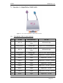
1
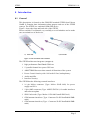
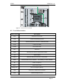
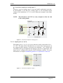
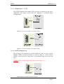
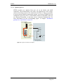
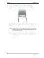
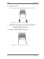
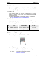
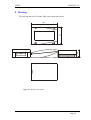
This document is available at HTTP://WWW.FALCOM.DE/ .
STEPP
Hardware description
Version 1.10
STEPP
VERSION 1.10
Index of contents
0
INTRODUCTION ..............................................................5
0.1
0.2
0.3
GENERAL ........................................................................................................................................ 5
USED ABBREVIATIONS .................................................................................................................... 6
RELATED DOCUMENTS.................................................................................................................... 7
1
SECURITY .........................................................................8
1.1
1.2
1.3
1.4
1.5
1.6
1.7
1.8
1.9
1.10
1.11
1.12
1.13
GENERAL INFORMATION ................................................................................................................. 8
EXPOSURE TO RF ENERGY .............................................................................................................. 8
EFFICIENT MODEM OPERATION ....................................................................................................... 8
ANTENNA CARE AND REPLACEMENT .............................................................................................. 9
DRIVING ......................................................................................................................................... 9
ELECTRONIC DEVICES..................................................................................................................... 9
VEHICLE ELECTRONIC EQUIPMENT ................................................................................................. 9
MEDICAL ELECTRONIC EQUIPMENT ................................................................................................ 9
AIRCRAFT ....................................................................................................................................... 9
CHILDREN .................................................................................................................................... 10
BLASTING AREAS .......................................................................................................................... 10
POTENTIALLY EXPLOSIVE ATMOSPHERES ..................................................................................... 10
NON-IONISING RADIATION ............................................................................................................ 10
2
SAFETY STANDARDS ...................................................11
3
TECHNICAL DATA........................................................12
4
FUNCTIONAL DESCRIPTION.....................................13
4.1.1.1
Determining the External Equipment Type .................................................................................................. 14
5
GSM CORE ......................................................................16
5.1
5.2
5.2.1
GENERAL ...................................................................................................................................... 16
GSM DATA SERVICES ................................................................................................................... 16
RF characteristics......................................................................................................................... 16
6
GPS CORE........................................................................18
6.1
6.2
6.2.1
GENERAL ...................................................................................................................................... 18
TECHNICAL DATA ......................................................................................................................... 18
NMEA data message ................................................................................................................... 18
7
HARDWARE INTERFACES .........................................19
7.1
7.1.1
7.1.2
INTERFACE A (16PIN MOLEX 43045-1609) .................................................................................. 20
Description of the 16- pin connector ........................................................................................... 20
Special pin description................................................................................................................. 21
7.1.2.1
7.1.2.2
7.1.2.3
7.1.2.4
7.1.2.5
Analog inputs (pin 2, 4)................................................................................................................................ 21
Inputs (pin 6, 8, 10, 12) ................................................................................................................................ 22
Outputs (pin 5, 7, 9, 11) ............................................................................................................................... 23
BATT On/Off (pin 14)................................................................................................................................... 23
Ignition (pin 13) ........................................................................................................................................... 24
7.2
7.3
7.4
7.4.1
7.4.2
INTERFACE B (SIM-CARD INTERFACE MOLEX-91228-0002) ....................................................... 25
INTERFACES C AND D................................................................................................................... 26
INTERFACE E (AMP 5-558556-1 CONNECTOR) ........................................................................... 26
The 15- pin connector description ............................................................................................... 27
Special pin description................................................................................................................. 27
7.4.2.1
7.4.2.2
7.4.2.3
7.4.2.4
VC 5 ............................................................................................................................................................. 27
Boot select .................................................................................................................................................... 28
RxA, TxA....................................................................................................................................................... 28
Speaker outputs characteristics.................................................................................................................... 28
This confidential document is a property of FALCOM GmbH and may not be copied or circulated without previous permission.
Page 1
STEPP
VERSION 1.10
7.5
INTERFACE F (LED’S DESCRIPTION) ............................................................................................ 28
8
HOUSING .........................................................................29
9
STEPP-MOUNTING BRACKET...................................30
10
APPENDIX .......................................................................31
10.1
10.1.1
10.1.2
SCHEMATICS................................................................................................................................. 31
Installation guidance for 16pin Molex connector ........................................................................ 31
Installation guidance for 15-pin AMP connector......................................................................... 32
This confidential document is a property of FALCOM GmbH and may not be copied or circulated without previous permission.
Page 2
STEPP
VERSION 1.10
Version history:
Version number
1.00
Author
Fadil Beqiri
1.01
Fadil Beqiri
1.02
J.Skeide
1.03
Fadil Beqiri
1.04
Fadil Beqiri
1.05
Fadil Beqiri
1.06
Fadil Beqiri
1.07
Fadil Beqiri
1.08
Fadil Beqiri
1.09
Fadil Beqiri
1.10
Fadil Beqiri
Changes
Initial version
Schematic example (figure 18)
optimize
Pin 14(Molex 16 pin) described
Table 9: output description
modified
Table 9: output description
modified
Schematics example (figure 8, 9)
optimize
Pin 14 in schematic example
(figure 18) added
The names of Pin (5 and 7) on the
Table 9 are changed.
Update of Pin 14 (BATT
ON/OFF)
Current consumption in Standby
updated.
The names of Pin (5 and 7) in the
Table 9 are changed.
New feature of the GPS LED
(yellow one) on the chapter 4
Functional description added.
Current consumption in Standby
mode removed.
Output 1 and 2 on the 16-pin
Molex connector exchanged to
pin 7 and 5 respectively (table 9
updated).
Figure 18 updated, too.
The BATT On/Off pin on the 16pin connector updated.
The schematic example (figure
18) improved (a 2A-Fuse added).
This confidential document is a property of FALCOM GmbH and may not be copied or circulated without previous permission.
Page 3
STEPP
VERSION 1.10
Cautions
Information furnished herein by FALCOM are accurate and reliable.
However, no responsibility is assumed for its use.
Please read carefully the safety precautions.
If you have any technical questions regarding this document or the
product described in it, please contact your vender.
General information about FALCOM and its range of products is
available at the following internet address: http://www.falcom.de/
Trademarks
Some mentioned products are registered trademarks of their respective
companies.
Copyright
The STEPP user’s guide is copyrighted by FALCOM GmbH with all
rights reserved. No part of this user’s guide may be produced in any form
without the prior written permission of FALCOM GmbH.
FALCOM GmbH.
No patent liability is assumed with respect to the use of the information
contained herein.
This confidential document is a property of FALCOM GmbH and may not be copied or circulated without previous permission.
Page 4
STEPP
VERSION 1.10
0 Introduction
0.1 General
This description is focused on the GSM/GPS terminal STEPP from Falcom
GmbH. It contains short information about purpose and use of the STEPP
concept. The STEPP is a combined GSM/GPS device.
Figure 1 shows the front and back side of the STEPP.
Please read this User Manual very carefully to avoid mistakes and to make
sure an optimal use of the device.
a) back side
b) front side
figure 1: front and back side of STEPP
The STEPP architecture integrates (see figure 2):
high-performance Dual-Band GSM core
12 parallel channel low-power GPS core
ARM7TDMI Processor that controls all functions of the system
Power Control circuitry with 1100 mAh Li-Ion, backup battery
Audio amplifier
Interface circuitry
The STEPP has the following external interfaces:
16 pin Molex connector (Type: Molex 43045-1609) for power
supply and I/O’s
15pin AMP connector (Type: AMP5-558556-1) for audio interfaces
and software update
SIM Card reader (Type: Molex-91228-0002 small SIM Card )
GSM antenna interfaces (Type: Connector 50 Ω Fakra/Radial SMBmale)
GSM antenna interfaces (Type : Connector 50 Ω Fakra/Radial SMBmale)
This confidential document is a property of FALCOM GmbH and may not be copied or circulated without previous permission.
Page 5
STEPP
VERSION 1.10
r
figure 2: Architecture of the STEPP
0.2 Used abbreviations
Abbreviation
Description
DOP
Dilution of Precision
GPS
Global Positioning System
GSM
Global Standard for Mobile Communications
GGA
GPS Fixed Data
HDOP
Horizontal DOP
HW
Hardware
IMEI
International Mobile Equipment Identity
I/O
Input/Output
NMEA
National Marine Electronics Association
PRN
Pseudorandom Noise Number – The Identity of GPS satellites
RF
Radio Frequency
RTC
Real Time Clock
RXQUAL
Received Signal Quality
SIM
Subscriber Identification Module
SMS
Short Message Service
This confidential document is a property of FALCOM GmbH and may not be copied or circulated without previous permission.
Page 6
STEPP
VERSION 1.10
Abbreviation
Description
SRAM
Static Random Access Memory
TA
Terminal Adapter
TE
Terminal Equipment
TP
Transmit Protocol
TTFF
Time to First Fix
SA
Selective Availability
WAAS
Wide Area Augmentation System
MSK
Minimum Shift Keying
table 1:
Used abbreviations
0.3 Related documents
1. ETSI GSM 07.05:“Use of Data Terminal Equipment–Data Circuit
terminating Equipment interface for Short Message Service and Cell
Broadcast Service”
2. ETSI GSM 07.07“AT command set for GSM Mobile Equipment”
3. ITU-T V.25ter“Serial asynchronous automatic dialling and control”
4. SiRF binary and NMEA protocol specification;
www.falcom.de/Service/Manuals/SiRF
This confidential document is a property of FALCOM GmbH and may not be copied or circulated without previous permission.
Page 7
STEPP
VERSION 1.10
1 Security
IMPORTANT FOR THE EFFICIENT AND SAFE OPERATION OF
YOUR GSM-MODEM, READ THIS INFORMATION BEFORE USE!
Your cellular engine STEPP is one of the most exciting and innovative
electronic products ever developed. With it you can stay in contact with
your office, your home, emergency services and others, wherever service is
provided.
This chapter contains important information for the safe and reliable use of
the STEPP. Please read this chapter carefully before starting to use the
cellular engine STEPP.
1.1 General information
Your STEPP device utilises the GSM/GPS standard for cellular technology.
GSM is a newer radio frequency („RF“) technology than the current FM
technology that has been used for radio communications for decades. The
GSM standard has been established for use in the European community and
elsewhere. Your modem is actually a low power radio transmitter and
receiver. It sends out and receives radio frequency energy. When you use
Your modem, the cellular system handling your calls controls both the radio
frequency and the power level of Your cellular modem.
1.2 Exposure to RF energy
There has been some public concern about possible health effects of using
GSM modem. Although research on health effects from RF energy has
focused for many years on the current RF technology, scientists have begun
research regarding newer radio technologies, such as GSM. After existing
research had been reviewed, and after compliance to all applicable safety
standards had been tested, it has been concluded that the product is fit for
use.
If you are concerned about exposure to RF energy there are things you can
do to minimize exposure. Obviously, limiting the duration of your calls will
reduce your exposure to RF energy. In addition, you can reduce RF
exposure by operating Your cellular modem efficiently by following the
guidelines below.
1.3 Efficient modem operation
In order to operate Your modem at the lowest power level, consistent with
satisfactory call quality please take note of the following hints.
If Your modem has an extendible antenna, extend it fully. Some models
allow you to place a call with the antenna retracted. However Your
modem operates more efficiently with the antenna fully extended.
Do not hold the antenna when the modem is „IN USE“. Holding the
antenna affects call quality and may cause the modem to operate at a
higher power level than needed.
This confidential document is a property of FALCOM GmbH and may not be copied or circulated without previous permission.
Page 8
STEPP
VERSION 1.10
1.4 Antenna care and replacement
Do not use the modem with a damaged antenna. If a damaged antenna
comes into contact with the skin, a minor burn may result. Replace a
damaged antenna immediately. Consult your manual to see if you may
change the antenna yourself. If so, use only a manufacturer-approved
antenna. Otherwise, have your antenna repaired by a qualified technician.
Use only the supplied or approved antenna. Unauthorized antennas,
modifications or attachments could damage the modem and may contravene
local RF emission regulations or invalidate type approval.
1.5 Driving
Check the laws and regulations on the use of cellular devices in the area
where you drive. Always obey them. Also, when using Your modem while
driving, please pay full attention to driving, pull off the road and park before
making or answering a call if driving conditions so require. When
applications are prepared for mobile use they should fulfil road-safety
instructions of the current law!
1.6 Electronic devices
Most electronic equipment, for example in hospitals and motor vehicles is
shielded from RF energy. However RF energy may affect some
malfunctioning or improperly shielded electronic equipment.
1.7 Vehicle electronic equipment
Check Your vehicle manufacturer’s representative to determine if any on
board electronic equipment is adequately shielded from RF energy.
1.8 Medical electronic equipment
Consult the manufacturer of any personal medical devices (such as
pacemakers, hearing aids, etc.) to determine if they are adequately shielded
from external RF energy.
Turn Your STEPP device OFF in health care facilities when any regulations
posted in the area instruct you to do so. Hospitals or health care facilities
may be using RF monitoring equipment.
1.9 Aircraft
Turn Your STEPP OFF before boarding any aircraft.
Use it on the ground only with crew permission.
Do not use it in the air.
To prevent possible interference with aircraft systems, Federal Aviation
Administration (FAA) regulations require you to have permission from a
crew member to use Your modem while the plane is on the ground. To
prevent interference with cellular systems, local RF regulations prohibit
using Your modem whilst airborne.
This confidential document is a property of FALCOM GmbH and may not be copied or circulated without previous permission.
Page 9
STEPP
VERSION 1.10
1.10 Children
Do not allow children to play with Your STEPP device. It is not a toy.
Children could hurt themselves or others (by poking themselves or others in
the eye with the antenna, for example). Children could damage the modem
or make calls that increase Your modem bills.
1.11 Blasting areas
To avoid interfering with blasting operations, turn Your unit OFF when in a
“blasting area” or in areas posted: „turn off two-way radio“. Construction
crew often use remote control RF devices to set off explosives.
1.12 Potentially explosive atmospheres
Turn Your STEPP device OFF when in any area with a potentially
explosive atmosphere. It is rare, but Your modem or its accessories could
generate sparks. Sparks in such areas could cause an explosion or fire
resulting in bodily injury or even death.
Areas with a potentially explosive atmosphere are often, but not always,
clearly marked. They include fuelling areas such as petrol stations; below
decks on boats; fuel or chemical transfer or storage facilities; and areas
where the air contains chemicals or particles, such as grain, dust or metal
powders.
Do not transport or store flammable gas, liquid or explosives, in the
compartment of Your vehicle which contains Your modem or accessories.
Before using Your modem in a vehicle powered by liquefied petroleum gas
(such as propane or butane) ensure that the vehicle complies with the
relevant fire and safety regulations of the country in which the vehicle is to
be used.
1.13 Non-ionising radiation
As with other mobile radio transmitting equipment users are advised that for
satisfactory operation and for the safety of personnel, it is recommended
that no part of the human body be allowed to come too close to the antenna
during operation of the equipment.
The radio equipment shall be connected to the antenna via a non-radiating
50 Ohm coaxial cable.
The antenna shall be mounted in such a position that no part of the human
body will normally rest close to any part of the antenna. It is also
recommended to use the equipment not close to medical devices as for
example hearing aids and pacemakers.
This confidential document is a property of FALCOM GmbH and may not be copied or circulated without previous permission.
Page 10
STEPP
VERSION 1.10
2 Safety standards
This GSM/GPS modem complies with all applicable RF safety standards.
The embedded GMS/GPS modem meets the safety standards for RF
receivers and the standards and recommendations for the protection of
public exposure to RF electromagnetic energy established by government
bodies and professional organizations, such as directives of the European
Community, Directorate General V in matters of radio frequency
electromagnetic energy.
This confidential document is a property of FALCOM GmbH and may not be copied or circulated without previous permission.
Page 11
STEPP
VERSION 1.10
3 Technical Data
General specification
Dimensions
55 mm x 80 mm x 22 mm (B x W x H)
Weight
approx. 120 g
table 2:
General specification dimensions
NOTE: The given current consumption in the table below is for a full
charged internal battery. In case of discharged battery the current
consumption rise up to 800 mA.
Power supply
V+ = 10.8 .. 32 V DC
Average current (in mA at 12 V nominal):
GPS on
(Continuous Mode)
/GSM
table 3:
900
1800
GSM band
70
70
in idle mode (base station sends at -85 dBm)
200
140
in transmit mode at maximum power level
Power supply and current consumption.
Temperature limits
Operation/Full GSM specification compliant
table 4:
Without ACCU
With ACCU
-20°C to +55°C
0°C to +55°C
Transportation
-20°C to +70°C
Storage
-30°C to +85°C
Temperature range
This confidential document is a property of FALCOM GmbH and may not be copied or circulated without previous permission.
Page 12
STEPP
VERSION 1.10
4 Functional description
The STEPP is a plug-and-play device that can be used as mobile Client in a
variety of:
-
AVL
-
fleet management and monitoring
-
car security and safety
system solutions.
Depending on the configuration, the device exchanges data with a server
application (e.g. Mapping-Software, etc.). The STEPP can be configured by
the user via local RS232-interface or via the GSM (air link).
For evaluation purposes FALCOM provides a demo software that enables
basic handling and visualisation of the received data.
The demo software can be used also for configuration of the device. Using
the "Configuration manager" the following settings can be done:
♦
History function (combinations between time, distance and velocity,
about 100.000 records possible)
♦
Setting alarm inputs (for each input individually configurable
telephone number, alarm text as SMS, last position)
♦
Automatic tracking (history or current position report by timer or
other event)
♦
Geo-fencing (send report when approaching pre-defined zone
coordinates)
For more information about the functions refer to the software description at
the Falcom’s home page: http://www.falcom.de/service/manuals/stepp.
The STEPP concept provides 6 inputs, 4 outputs and 2 analog inputs. Of the
6 inputs 4 are available to the user and 2 are defined at the factory.
Two of the inputs are pre-assigned at the factory:
-
Power Supply - connect to vehicle battery (clamp 30).
-
Ignition - connect to starter lock (clamp 15).
The internal backup Battery (LiIon- 1100 mAh) is available in case of
external Power failure.
An audio interface allows the direct connection of a headset.
An example of a possible installation is shown in the Appendix of this
manual.
This confidential document is a property of FALCOM GmbH and may not be copied or circulated without previous permission.
Page 13
STEPP
VERSION 1.10
The actual status of the STEPP is displayed by two LED’s on the top of
modem.
•
•
•
•
•
•
Green ON: Power ON, not registered in the network.
Green flashes (2 sec. interval): Power on, registered in the network.
Green flashes quickly: Call in progress.
Yellow ON: GPS- Coordinates are not available or invalid.
Yellow flashes (4 sec. interval): Start-up GSM error (i.e. no SIM card
inserted or incorrect PIN configuration or is not
ready for operation)
Yellow flashes: GPS- Positions are available and valid.
4.1.1.1 Determining the External Equipment Type
Before you connect the serial port pins on the aforementioned terminals
(DCE units) to external equipment, you need to determine if the external
hardware serial ports are configured as DTE or DCE.
The terms DTE (Data Terminal Equipment) and DCE (Data
Communications Equipment) are typically used to describe serial ports on
devices. Computers (PCs) generally use DTE connectors and
communication devices such as modems and DSU/CSU devices generally
use DCE connectors. As a general rule, DTE ports connect to DCE ports via
straight through pinned cables. In other words, a DTE port never connects
directly to another DTE port. Similarly, a DCE port never connects directly
to another DCE port. The signaling definitions were written from the
perspective of the DTE device; therefore, a Receive Data signal becomes an
input to DTE but an output from DCE.
For cabling, to connect a DTE device to a DCE device, all you need is a
straight through pinned cable.
However, to connect two DTE devices (for example, PC to PC), to transfer
data over their serial ports you need a cross pinned cable to simulate the
missing pair of DCE devices (modems or DSU/CSUs). This cable is usually
called a null modem cable because DCE devices are typically modems.
The Falcom STEPP is designed for use as a DCE. Based on the
aforementioned conventions for DCE-DTE connections it communicates
with the customer application (DTE) using the following signals:
TANGO Terminal (DCE)
to
Application (DTE)
TxD
◄-----------------------
TXD
RxD
-----------------------►
RXD
RTS
◄-----------------------
RTS
CTS
-----------------------►
CTS
DTR
◄-----------------------
DTR
DSR
-----------------------►
DSR
This confidential document is a property of FALCOM GmbH and may not be copied or circulated without previous permission.
Page 14
STEPP
VERSION 1.10
DCD
-----------------------►
DCD
RING
-----------------------►
RING
Table 8: The signaling definitions between DTE and DCE.
This confidential document is a property of FALCOM GmbH and may not be copied or circulated without previous permission.
Page 15
STEPP
VERSION 1.10
5 GSM Core
5.1 General
The modem engine inside the STEPP operates on GSM 900 MHz and GSM
1800 MHz frequency bands.
5.2 GSM data services
300....14400 BPS, asynchronous, transparent and non-transparent
(V.21, V.22, V.23, V.22bis, V.26ter, V.32, V.34, V.110)
5.2.1
RF characteristics
Receiver
EGSM Sensitivity
< -104 dBm
DCS Sensitivity
< -100 dBm
Selectivity @ 200 kHz
> +9 dBc
Selectivity @ 400 kHz
> +41 dBc
Dynamic range
62 dB
Intermodulation
> -43 dBm
Co-channel rejection
≥ 9 dBc
table 5:
Receiver characteristics of the integrated GSM Core
Transmitter
Maximum output power (EGSM)
33 dBm ± 2 dB
Maximum output power (DCS)
30 dBm ± 2 dB
Minimum output power (EGSM)
5 dBm ± 5 dB
Minimum output power (DCS)
0 dBm ± 5 dB
H2 level
≤ 30 dBm
H3 level
≤ 30 dBm
Noise in 925....935 MHz
≤ 67 dBm
This confidential document is a property of FALCOM GmbH and may not be copied or circulated without previous permission.
Page 16
STEPP
VERSION 1.10
Noise in 935....960 MHz
≤ 79 dBm
Transmitter
Noise in 1805....1880 MHz
≤ 71 dBm
Phase error at peak power
< 5° RMS
Frequency error
± 0.1 ppm max
table 6:
Transmitter characteristics of the integrated GSM Core
This confidential document is a property of FALCOM GmbH and may not be copied or circulated without previous permission.
Page 17
STEPP
VERSION 1.10
6 GPS core
6.1 General
The GPS Core is a single-board 12 parallel channel receiver.
6.2 Technical data
FEATURES
Integrated 12 parallel channel GPS
Protocols available:
RXA/TXA: NMEA 4800 baud, Msg.: GLL,
GGA, RMC, , GSV, GSA,
8 data bits, no parity, 1 stop bit
6.2.1 NMEA data message
The STEPP device delivers data in the NMEA-0183 format.
Table 7 lists each of the NMEA output messages supported by the STEPP
evaluation receiver and a brief description.
For further description about NMEA see Related documents[4]
Option
Description
GGA
Time, position and fix type data.
GLL
Latitude, longitude, UTC time of position fix and status.
GSA
GPS receiver operating mode, satellites used in the position solution
and DOP values.
GSV
The number of GPS satellites in view satellite ID numbers, elevation,
azimuth and SNR values.
RMC
Time, date, position, course and speed data.
table 7:
NMEA Output Messages
This confidential document is a property of FALCOM GmbH and may not be copied or circulated without previous permission.
Page 18
STEPP
VERSION 1.10
7 Hardware Interfaces
This chapter describes the hardware interfaces:
•
•
•
•
•
pinout on the 16-pin (Molex) connector
pinout on the 15-pin (AMP) connector
RF interface
SIM interface
LED’s indicator
Interface specifications
Interface A
Interface B
16pin Molex 43045-1609
SIM card reader for small SIM cards (3V)
Interface C
GPS RF Connector 50 Ω Fakra/Radial (SMB-Male)
Interface D
GSM RF Connector 50 Ω Fakra/Radial (SMB- Male)
Interface E
15pin AMP5-558556-1
Interface F
Optical GSM/GPS LED’s
table 8:
Interface specifications
figure 3: Interface specifications
This confidential document is a property of FALCOM GmbH and may not be copied or circulated without previous permission.
Page 19
STEPP
VERSION 1.10
7.1 Interface A (16pin Molex 43045-1609)
figure 4: View of the 16pin Molex 43045-1609 connector
7.1.1
Description of the 16- pin connector
PIN
NAME
DISCRIPTION
LEVEL
1
MIC N1
Microphone 1 negative
input
differential input
2
Analog Input 2
Analog input
up to 32 V / 8 bit resolution
3
MIC P1
Microphone 1 positive
input
differential input
4
Analog Input 1
Analog input
up to 32 V DC / 8 bit resolution
5
Output 2
output
Output 10.8 .. 32V DC/ 100 mA
6
Input 4
input
Input 10.8 .. 32V DC
7
Output 1
output
Output 10.8 .. 32V DC / 100mA
8
Input 3
input
Input 10.8 .. 32V DC
9
Output 3
output
Output 10.8 .. 32V DC / 100 mA
10
Input 2
input
Input 10.8 .. 32V DC
11
Output 4
output
Output 10.8 .. 32V DC / 100 mA
12
Input 1
input
Input 10.8 .. 32V DC
This confidential document is a property of FALCOM GmbH and may not be copied or circulated without previous permission.
Page 20
STEPP
VERSION 1.10
PIN
NAME
DISCRIPTION
LEVEL
13
Ignition
Input 8
Input 10.8 .. 32V DC
connected to GND:
Switch ON/OFF the -switch the internal Battery ON
internal LiIon-Battery. and the battery would be
charged
Do not connect this disconnected from GND:
pin to power supply -switch the internal Battery OFF
and the battery wouldn’t be
(V+).
charged
14
BATT On/Off
(Key Accu on
Eval board)
15
V+
Power supply Input 7
16
GND
GROUND
Input 10.8 .. 32V DC
table 9: Pin discription of 16pin Molex connector
7.1.2
Special pin description
7.1.2.1 Analog inputs (pin 2, 4)
Analog voltages up to 32 V with a resolution of 8 bit can be processed and
remotely evaluated by a server application.
↓ Connection example for analog input 2:
Pin 2 (analog input 2) can be connected to a temperature sensor (a NTC
resistor for instance) with restriction values, if the temperature rises/falls,
the STEPP reacts, and sends a message (SMS with voltage values
depending on the user configuration) to the receiving device (mobile phone,
modem or any GSM device), see the illustrated example in the figure below.
2
1
Constant Input
10.8 .. 32 V
Analog input 2
16
15
NTC
Falcom STEPP
pin connector
GND
User application
figure 5: Connection example for analog input 2
This confidential document is a property of FALCOM GmbH and may not be copied or circulated without previous permission.
Page 21
STEPP
VERSION 1.10
↓ Connection example for analog input 1:
Likewise, on pin 4 (analog input 1) you can install a tachometer generator.
Its functionality is just like pin 2 (analog input 2). The maximum output
voltage of the tachometer is 32 V (see the illustrated example in the figure
below).
NOTE: The tachometer and NTC are only examples to show the aim
of the analog inputs.
2
1
Const. Input
up to 32 V
16
15
Analog input 1
Falcom STEPP
pin connector
GND
GND
User application
figure 6: Connection example for analog input 1
7.1.2.2 Inputs (pin 6, 8, 10, 12)
The Inputs (pin 6, 8, 10, 12) of 16-pin connector can be connected to 10.8 ..
32 V DC. The figure below illustrates how to connect these inputs. If one of
the connected pins (inputs) is activated (for minimum 1 sec), STEPP will
send SMS with a pre-configured text massage to the Server application. The
inputs can be configured by using the FALCOM demo software. For more
information see chapter Installation guidance for 16pin Molex connector.
2
1
Input 10.8 .. 32 V DC
16
15
input 4
Falcom STEPP
pin connector
User application
figure 7: Connection example for input 4
This confidential document is a property of FALCOM GmbH and may not be copied or circulated without previous permission.
Page 22
STEPP
VERSION 1.10
7.1.2.3 Outputs (pin 5, 7, 9, 11)
The STEPP supports four outputs. These can be set remotely by the server
application. The figures below show the schematic of possible output
configurations.
figure 8: Connection example 1 for output 4 (Relay)
figure 9: Connection example 2 for output 4 (LED)
7.1.2.4 BATT On/Off (pin 14)
This pin has to be connected to ground (GND) in order to power on the
Falcom STEPP via internal battery as well to charge it. If the Falcom
STEPP is not in use for a long time (e.g warehouse) this pin can be left
open.
2
1
Caution: Please do not connect this pin to power supply (V+).
BATT ON/OFF
16
15
GND
Falcom STEPP
pin connector
figure 10: BATT ON/OFF connection example
This confidential document is a property of FALCOM GmbH and may not be copied or circulated without previous permission.
Page 23
STEPP
VERSION 1.10
7.1.2.5 Ignition (pin 13)
STEPP provides two Ignition Pins (pin 13) on the Molex and AMP
connectors. Their functionality is the same. The Ignition line of the vehicle
(starter lock clamp 15) has to be connected to the Pin 13. Thus it is possible
to send an Alarm SMS (by starting the engine), provide the STEPP has been
configured respectively. Pin 13 of the Molex connector and AMP connector
are connected internally, so that they can be connected alternatively. For
more information see the corresponding figure in chapter “Installation
guidance for 16pin Molex connector”.
Falcom STEPP
15-pin connector
1
Ignition
15
(car key
contact)
V+
GND
16-pin connector
clamp motor vehicle
2
1
15
16
15
internal connection
Ignition
Batt(+)
30
31
Batt(-)
10.8 .. 32 V
DC
User application
figure 11: Ignition connection example
This confidential document is a property of FALCOM GmbH and may not be copied or circulated without previous permission.
Page 24
STEPP
VERSION 1.10
7.2 Interface B (SIM-Card interface Molex-91228-0002)
The figure below shows the SIM-card reader interface of the STEPP.
figure 12: View of the SIM Card reader
The SIM interface controls a internal small 3V SIM Card. This interface is
fully compliant with GSM 11.11 recommendations concerning SIM
functions.
Note: The SIM should not be removed, while the module is powered on.
The SIM must only be removed when the STEPP is shut down. To
remove the SIM card press the Eject button (see figure 12) then
pull out the SIM card reader.
Note: The unit is not designed for use of single 5 V SIM cards. These
cards will generate an error which cannot be distinguished from a
faulty SIM card.
This confidential document is a property of FALCOM GmbH and may not be copied or circulated without previous permission.
Page 25
STEPP
VERSION 1.10
7.3 Interfaces C and D
The below figure shows the GPS/GSM Antenna interfaces of the STEPP.
figure 13: View of the GSM/GPS antenna cable.
Both GSM/GPS-antenna cables are connected to STEPP. Both of them have
a SMB connector. The GSM antenna cable is longer than GPS antenna.
⇒ GPS-antenna cable: 87.60 mm (colour blue)
⇒ GSM-antenna cable: 99.00 mm (colour bordeaux)
7.4 Interface E (AMP 5-558556-1 Connector)
Figure 14: View of the 15pin AMP5-558556-1 connector
This confidential document is a property of FALCOM GmbH and may not be copied or circulated without previous permission.
Page 26
STEPP
7.4.1
VERSION 1.10
The 15- pin connector description
PIN
NAME
DISCRIPTION
1
GND
GROUND
2
GND
GROUND
3
SPK N1
Speaker 1 negative output
differential output
4
SPK P1
Speaker 1 positive output
differential output
VC 5
Power supply output
5 V DC output
max 100 mA
6
V Accu
Battery controller
3,3 .. 4,2 V DC
7
MIC N2
Microphone 2 negative input
differential input
8
MIC P2
Microphone 2 positive input
differential input
9
SPK N2 with amplifier
Speaker 2 negative output
8Ω/1W
10
SPK P2 with amplifier
Speaker 2 positive output
8Ω/1W
11
Boot select
Connect to GND in case of
firmware update. For a
normal STEPP operation
leave it floating
12
Ring PWM
80 mA max output
CMOS 2,8 V output
13
Ignition
input 8
Input 10.8 .. 32V
14
RxA RS232
Receive serial data
V24, ±12 V output
15
TxA RS232
Transmit serial data
V24, ±12 V input
5
LEVEL
table 10: Pins discription of 15pin AMP connector
7.4.2
Special pin description
7.4.2.1 VC 5
This output can be used to power some external functions. VC 5 has to be
used as a power supply. This power supply is available when the module is
on.
To use this pin see chapter Installation guidance for 16pin Molex connector
at the end of this manual.
This confidential document is a property of FALCOM GmbH and may not be copied or circulated without previous permission.
Page 27
STEPP
VERSION 1.10
7.4.2.2 Boot select
To update a new STEPP firmware, this pin should be connected to GND.
For a normal STEPP operation (tracking, call, etc.) this pin shouldn’t be
connected (leave floating).
7.4.2.3 RxA, TxA
Using the RS232-Signals RxA and TxA, a communication to a PC serial
port can be established. In this way the device can be configured using the
SteppConfig software.
The SteppConfig is available on the Falcom’s Website for free download:
www.falcom.de/service/downloads/manual/stepp
7.4.2.4 Speaker outputs characteristics
A speaker can be connected directly to the pin 9 and pin 10. The standard
level is 8 Ω / 1 Watt. We recommend loudspeakers with more power for
better voice quality. See table below.
PIN
NAME
DESCRIPTION
LEVEL
9
SPK N2 with amplifier
Speaker 2 negative output
8Ω/5W
10
SPK P2 with amplifier
Speaker 2 positive output
8Ω/5W
table 11: Description of recommended speaker characteristics.
7.5 Interface F (LED’s description)
The below figure shows the GSM/GPS LED’s on STEPP.
figure 15: View of the GSM/GPS LED’s.
The two LED’s show the state of the STEPP:
• Green:
GSM network (about its functionality see chapter
Functional description).
•
Yellow:
GPS (about its functionality see chapter
Functional description).
This confidential document is a property of FALCOM GmbH and may not be copied or circulated without previous permission.
Page 28
STEPP
VERSION 1.10
8 Housing
The housing material: Galvano-ABS, gloss-chromium-plated.
25
55
80
figure 16: Housing of the STEPP.
This confidential document is a property of FALCOM GmbH and may not be copied or circulated without previous permission.
Page 29
STEPP
VERSION 1.10
30
75
55
49
9 STEPP-Mounting bracket
25
80
R1
O 3
O 2.5
R66.25
R0.5
O 2.4
O 4.2
O 6
figure 17: Mounting bracket of the STEPP
This confidential document is a property of FALCOM GmbH and may not be copied or circulated without previous permission.
Page 30
STEPP
VERSION 1.10
10 Appendix
10.1 Schematics
The figures below illustrate the recommended schematics for the connection
of the 16 pin Molex and 15 pin AMP connectors.
10.1.1 Installation guidance for 16pin Molex connector
On the top of the schematic the corresponding pin out of the 16-pin Molex
connector can be found.
The STEPP provides 6 inputs, 4 outputs and 2 analog inputs.
Of the 6 inputs, 4 input are free available for the user. Two of the inputs are
pre-assigned at the factory:
-
Power Supply - connect to vehicle battery (clamp 30).
-
Ignition - connect to starter lock (clamp 15).
Ensure that the operating voltage (V+) of the terminal and external power
source (i.e. car battery) incorporates a protection circuit against over current,
which has to be limited to 2 A at +10.8 … +32 VDC. See circuit diagram
below.
A microphone can be connected to pin 1 and pin 3 of the 16-pin Molex
connector.
The figure 18 shows an example for the installation of the STEPP-I/O’s in a
motor vehicle.
figure 18: Schematic example of installation guidance
This confidential document is a property of FALCOM GmbH and may not be copied or circulated without previous permission.
Page 31
STEPP
VERSION 1.10
10.1.2 Installation guidance for 15-pin AMP connector
Figure 19 shows an example of an installation that enables voice
communication.
STEPP supports two differential microphone inputs and two differential
speaker outputs.
The integrated amplifier allows direct connection of a Hands-Free- to Pin 9
and Pin 10.
figure 19: Possible installation for enabling voice connection.
This confidential document is a property of FALCOM GmbH and may not be copied or circulated without previous permission.
Page 32