1
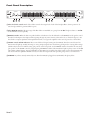
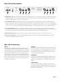
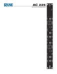
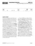
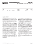
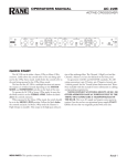
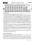
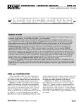
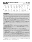
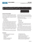
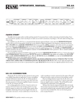
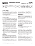
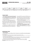
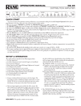
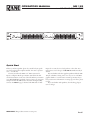
OPERATORS MANUAL
ME 15S
microGRAPHIC EQUALIZER
CHANNEL 1
4
6
2
25
±12
8
±6
0
63
100 160 250 400 630
1k
1.6k 2.5k
BYPASS
4k
6.3k 10k
CHANNEL 2
16k
+
12
3
6
0
0
3
6
6
12
•
•
•
•
10
OL LEVEL
40
+
6
•
•
•
•
RANGE
4
6
2
25
±12
8
±6
0
OL LEVEL
BYPASS
RANGE
63
100 160 250 400 630
1k
1.6k 2.5k
4k
6.3k 10k
16k
+
12
3
6
0
0
3
6
6
12
•
•
•
•
10
40
+
6
•
ME 15S
•
MICROGRAPHIC
EQUALIZER
•
•
POWER
Quick Start
If this is your first equalizer, please do yourself and your speakers a favor and read the complete manual. “An ounce of prevention...,” and all that.
You may use either the XLR or ¼" TRS connectors for
Inputs or Outputs. Hook-up is intuitive. Just follow the silkscreened instructions on the rear of the unit. Polarity convention
is per IEC/ANSI/AES standards of pin 2 positive, pin 3 negative
and pin 1 shield. The ME 15S does not invert the signal. Only
connect one INPUT type per channel. The XLR and ¼" TRS
WEAR PARTS: This product contains no wear parts.
Inputs do not sum, don’t use both, pick one or the other. You
may, however, use both types of OUTPUTS simultanesously if
desired.
Anyone familiar with other graphic equalizers finds the ME
15S just as familiar. Setting curves is as easy as it is on all Rane
graphics thanks to our innovative constant-Q circuitry. If you
feel you want more information on setting up your curves, please
read on.
If you are familiar with equalizers, then hook-up, plug-in,
turn-on and go!
Manual-
Front Panel Description
CHANNEL 1
4
6
2
25
±12
3
4k
6.3k 10k
CHANNEL 2
16k
3
6
0
0
3
6
6
12
•
•
•
RANGE
2
1.6k 2.5k
•
•
BYPASS
1k
+
12
•
10
4
100 160 250 400 630
•
±6
OL LEVEL
63
•
8
0
40
+
6
4
6
2
±12
100 160 250 400 630
1k
1.6k 2.5k
4k
6.3k 10k
16k
+
12
3
6
0
0
3
6
6
12
•
3
•
RANGE
2
MICROGRAPHIC
EQUALIZER
•
•
BYPASS
ME 15S
•
•
10
4
63
•
±6
0
40
•
8
OL LEVEL
1
25
+
6
POWER
1
5
1 Filter level slide controls: Each of these sliders controls the output level of each of the bandpass filters. Center position is detented and grounded for guaranteed flat response.
2 Filter RANGE switches: The gain range of the filter sliders is switchable (as a group) from ±6 dB for high resolution, to ±12 dB
for maximum boost/cut capability.
3 BYPASS switches: When the button is pushed and the red indicator is lit, this Channel is in the BYPASS mode: signal is routed
directly from the Input to the Output without passing through any active circuitry (often referred to as “hard‑wire bypass”). Use
this switch to compare equalized and unequalized material, or to bypass the equalizer in the event of power loss or unit failure.
4 LEVEL controls and OL indicators: These control the level of signal coming into the ME 15S. Turn this control down if it’s
OL (OverLoad) lights up steadily (meaning too strong an Input signal). Since actual unity gain depends on varying slider settings
(which is why we have not marked a unity gain position on the front panel), use the BYPASS switch to determine the exact unity
gain position of this LEVEL control by comparing EQ and BYPASS volumes. The OL indicator lights up if any section of the ME
15S is within 3 dB of clipping. Occasional blinking of these LEDs are acceptable, but if they remain on more than intermittently,
turn down either the equalizer’s LEVEL control(s) or reduce the output level of the preceding component to avoid distortion.
5 POWER: As you have astutely surmised by now, when the ME 15S is plugged into 85-240 VAC, this glows yellow.
Manual-
Rear Panel Description
100-240 V
50/60 Hz 7 WATTS
ME 15S
COMMERCIAL AUDIO
EQUIPMENT 24TJ
WIRING
CHANNEL 2
MADE IN U.S.A.
RANE CORP.
OUTPUT
INPUT
3
2
TIP / PIN 2 = POSITIVE
RING / PIN 3 = NEGATIVE
SLEEVE = SIGNAL GROUND
PIN 1 = CHASSIS GROUND
R
ACN 001 345 482
5
4
1
CHANNEL 1
This device complies with Part 15 of
the FCC Rules. Operation is subject
to the following two conditions:
(1) this device may not cause
harmful interference, and (2) this
device must accept any interference
received, including interference that
may cause undesired operation.
4
OUTPUT
INPUT
3
2
1
1 XLR INPUT jacks: These accommodates balanced signals. Rane adheres to the international and U.S. standard for balanced pin
configurations: Pin 1 is chassis ground (neutral), pin 2 is hot (positive), and pin 3 is signal return (negative). Choose between this
and the ¼" TRS Input jack—use only one—they do not sum.
2 ¼" TRS INPUT jacks: These TRS (tip-ring-sleeve) ¼" jacks accommodate either balanced or unbalanced signals. Balanced
signals use microphone cable (two conductor with shield) with TRS ¼" plugs. Unbalanced signals use a mono ¼" TS plug (single
conductor with shield), with its length kept under 10 feet (3 meters) to avoid hum and noise. Choose between this and the XLR Input
jack—use only one—they do not sum. Refer to the included RaneNote, “Sound System Interconnection” for unbalanced wiring.
3 ¼" TRS OUTPUT jacks: These are TRS (tip-ring-sleeve) ¼" balanced jacks compatible with either balanced or unbalanced
systems. For balanced systems, use a microphone cable wired with pin 1 is chassis ground (neutral), pin 2 is hot (positive), and pin
3 is signal return (negative). Refer to the RaneNote, “Sound System Interconnection” for unbalanced wiring.
4 XLR OUTPUT jacks: These balanced outputs are wired per AES standards of pin 2 “hot”, as described above in 1.
5 Universal Voltage Input: via a miniature IEC 60320 C6 appliance inlet. This mates with an IEC 60320 C5 line cord (USA
domestic). Do not lift the ground connection!
ME 15S Connection
INPUTS
Both XLR and ¼" TRS Inputs are wired in parallel and are
actively balanced. Each works equally well. Choose strictly from
a required hardware point-of-view, there will be no performance
trade-offs. The wiring convention adheres to American, British
and International standards of pin 2 or tip being hot, pin 3 or
ring being return, and pin 1 or sleeve being shield. Unbalanced
operation involves using only pin 2 or tip as signal, and pin 1 or
sleeve as shield or ground. It is not necessary to short any inputs
to ground—it doesn’t hurt, it’s just not necessary. Use pin 1, or
the shell, for shield ground.
OUTPUTS
The Outputs mimic the Inputs. Balanced output requires using
pin 2 or tip, and pin 3 or ring for the signal. It does not require
pin 1 or shield. The signal exists differentially between the two
balanced leads; ground is not involved. For hum-free systems
ground is used only for shielding.
EXPANDING
Expanding and/or daisychaining the Inputs and Outputs normally uses the ¼" jacks. Three parallel Input connectors allows
driving a second signal processor or amplifier without special
cabling.
SIGNAL LEVELS
Signal levels from -10 dBV to +4 dBu are considered normal
and within range (at least 20 dB of headroom exists above these
levels). Do not directly connect microphones into the ME 15S.
These require a mic preamp.
Manual-
Operating Instructions
Insuring the proper level of gain though the ME 15S is just as
important as adjusting the equalizer bands. Improper gain distribution is a common cause of loss of system headroom and less
than optimum noise performance.
The OverLoad LED informs of an imminent or passed
overload to the equalizer. Occasional blinking of the OL with
program source material is fine, indicating optimized signalto-noise performance of the ME 15S. Run the ME 15S with an
input signal that is as hot as possible without the OL lighting
more than occasionally.
The BYPASS switch allows comparison of equalized versus
un-equalized signal. It is also useful in adjusting the level of the
ME 15S for unity gain and best signal-to-noise performance. The
gain of the ME 15S is optimized when there is no sound level
difference between the bypassed and the active positions.
The overall gain range of the level control for the ME 15S
is off to +6 dB for unbalanced operation, or off to +12 dB for
balanced operation. The level difference between the equalizer in
bypass or active can be significant. Adjust the LEVEL control so
the signal level is the same between the bypassed and active positions of the BYPASS switch.
GETTING STARTED
Here is one method of setting your equalizer that works well.
Begin with the following settings:
1. Engage the BYPASS switch. (switch depressed, BYPASS LED
on.)
2. Put all sliders in their center position (0 dB). The center position has a grounded detent.
3. Position the LEVEL controls about “6” for unbalanced operation and “7” for balanced operation.
4. Apply a signal to the system.
5. Verify the OL LED is not on—occasionally blinking during
extreme peaks indicates an optimal setting. But if it lights up
a lot or lights steadily, lower the output level of the previous
device in the signal chain.
6. Release the BYPASS switch and begin adjusting the equalizer
filters.
7. During filter band adjustments, if the OL LED lights more
than occasionally, turn down the output of the previous device in the signal chain.
8. Once all filter bands are adjusted to your liking, compare the
signal loudness with the equalizer bypassed and active. Adjust
the LEVEL controls on the ME 15S so there is no difference
between the levels of bypassed versus active.
9. The last step is to reconfirm that the OL LED lights only
when there are large signal spikes in the program material, as
in step 5 above.
For insight into how to use an equalizer, to alleviate acoustic
problems or to adjust the overall tone of the program material,
please read the following two sections.
ACOUSTIC COMPENSATION
A graphic equalizer may be used to correct many acoustic
problems. However, one should fully understand the ramifications of doing so. Acoustic problems are generally not consistent
across the entire area of sound coverage. This is much more of a
problem when setting up a sound system for large venues. In a
typical large room or hall, there will be areas that have acoustic
reinforcement problems and other areas where certain frequencies are almost entirely canceled out. Try to seek an acoustic
remedy for acoustic problems whenever possible. When this is
not possible or feasible, an equalizer may be used to compensate
for an acoustic problem. But the problem is only improved at
the point where the measurement is taken, other locations in the
room may be adversely affected by the equalizer setting. For this
reason, measure the acoustic response of the system from several
locations and average the equalizer’s setting. Doing this helps
most locations in the venue to have an equal sound quality.
The best way to “see” what the acoustic signature of the room
is doing to sound is to use a real time analyzer or any of the
many computerized measurement systems. Using these devices
to analyze the response of the room and the sound system is the
only accurate means available for setting an equalizer properly.
Equalization can be like spice in the hands of a master chef.
A little goes a long way in improving sound quality, too much
and the mix is spoiled. If modest amounts of equalization (6-8
dB) do not solve the problem, it is best remedied by other means.
Avoid adding large amounts of boost below 63 Hz, especially
when using vented bass cabinets. Boosting frequencies below
the vented enclosure’s low frequency cutoff can easily cause over
excursion of the speaker’s cone, causing premature failure. In addition, boosting low frequencies can make your power amplifier
run hotter, leading to premature amplifier failure.
When equalizer adjustment is completed, compare the unequalized sound with the equalized sound by alternately engaging the BYPASS switch. Use familiar source material and walk
around in the sound coverage area to insure that no anomalies
have been introduced into the sound system. If it sounds good,
you’re done.
TONE CONTOURING
If a ME 15S is used for tone contouring by ear, be careful about
adding upper bass (63 Hz to 200 Hz) as this causes “muddiness” or loss of definition. (Also see the previous warning about
boosting frequencies below 63 Hz.) Middle frequency problems
usually express themselves by vocals having a nasal quality (too
much mid band boost) or vocals not being easily understandable
(usually caused by mid band frequencies being under represented
in the overall sound). High band problems show as “sizzle”— not
good, and is sometimes caused by too much high frequency
boosting. This is most obvious with cymbals and hi-hats. To
use the cooking metaphor, high frequencies should simmer, not
sizzle.
©Rane Corporation 10802 47th Ave. W., Mukilteo WA 98275-5098 USA TEL 425-355-6000 FAX 425-347-7757 WEB www.rane.com
Manual-
109720