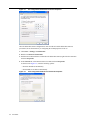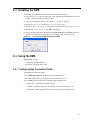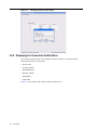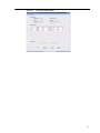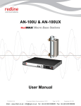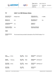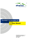
1
StarMAXTM 2100 Series Subscriber Station
User Guide
Version 1.0
StarMAXTM 2100
Version 2.0
User Guide
November 2006
Draft Revised on December 22, 2006
Copyright Information
Copyright 2006, Telsima Corporation 3945 Freedom Circle Suite 130 Santa Clara, CA, 95054,
All Rights Reserved. This document is the property of Telsima, and contains information
protected by copyright laws. The information in this document is subject to change without
notice. The information in this document is believed to be accurate and reliable. However, users
must take full responsibility for their applications of any products specified in this document.
Telsima, Telsima logo, StarMAX, TRUFLE, TelsiNex, TelsiView and OptiFlow are the
trademarks of Telsima Corporation. Copyright 2004 – 2006 Telsima Corporation. All rights
reserved. All other trademarks and registered trademarks are the property of their respective
owners.
Limited Warranty
“Above and beyond” is the standard we set ourselves for customer service at Telsima. It’s all part
of our commitment to Customer Satisfaction. All Telsima products are warranted and tested to be
free from defects in material and workmanship and to conform to the published specifications.
During the warranty period should this Telsima product fail under normal use in the
recommended environment due to improper workmanship or materials, Telsima will repair the
product or replace it with a comparable one. This warranty is subject to the conditions and
limitations set forth herein and is superseded by any contractual terms and conditions you may
have agreed with Telsima as part of a service contract.
Limitations
Telsima will not be liable for damages resulting from improper installation, alteration, acts of
nature, improper usage, or problems with electrical power. Telsima products must be used with
devices that confirm to the recommended industry standards. Telsima will not be liable for
damages resulting from a third party device that causes the Telsima product to fail. Telsima shall
in no event be liable for any consequential, indirect, or incidental damages, lost profits, lost
business investments, lost goodwill, or interference with business relationships as a result of lost
data. Telsima is also not responsible for damage or failure of any third party equipment, even if
Telsima has been advised of the possibility. This limitation does not apply to the extent that is
illegal or unenforceable under applicable law.
Disclaimer
The foregoing limited warranty is exclusive. There are no other warranties, including any implied
warranty of merchantability or fitness for a particular purpose. This warranty is not affected in
any part by Telsima providing technical support or advice.
Table of Contents
Preface
Audience . . . . . . . . . . . . . . . . . . . . . . . . . . . . . . . . . . . . . . . . . . . . . . . . . . . . . . . . . . . . . . . . . . . . . v
Related Information . . . . . . . . . . . . . . . . . . . . . . . . . . . . . . . . . . . . . . . . . . . . . . . . . . . . . . . . . . . . v
Contact Us . . . . . . . . . . . . . . . . . . . . . . . . . . . . . . . . . . . . . . . . . . . . . . . . . . . . . . . . . . . . . . . . . . . v
Conventions . . . . . . . . . . . . . . . . . . . . . . . . . . . . . . . . . . . . . . . . . . . . . . . . . . . . . . . . . . . . . . . . . . v
Abbreviations and Definitions . . . . . . . . . . . . . . . . . . . . . . . . . . . . . . . . . . . . . . . . . . . . . . . . . . . vi
Chapter 1 Overview of StarMAXTM Subscriber Station
1.1
1.2
1.3
1.4
Introducing StarMAXTM . . . . . . . . . . . . . . . . . . . . . . . . . . . . . . . . . . . . . . . . . . . . . . . . . . . . . . . . . . . . 1-1
Brief description of the StarMAXTM Subscriber Station . . . . . . . . . . . . . . . . . . . . . . 1-1
Element Management System for StarMAXTM Subscriber Station . . . . . . . . . . . . . . 1-2
Specifications. . . . . . . . . . . . . . . . . . . . . . . . . . . . . . . . . . . . . . . . . . . . . . . . . . . . . . . . 1-2
Chapter 2 Subscriber Commissioning
2.1
2.2
2.3
2.3.1
2.4
Configuring Basic Parameters . . . . . . . . . . . . . . . . . . . . . . . . . . . . . . . . . . . . . . . . . . .
Aligning Subscriber Unit Antenna . . . . . . . . . . . . . . . . . . . . . . . . . . . . . . . . . . . . . . .
Operational Verification of the Subscriber Station . . . . . . . . . . . . . . . . . . . . . . . . . . .
Verifying Data connectivity . . . . . . . . . . . . . . . . . . . . . . . . . . . . . . . . . . . . . . . . .
Required Information . . . . . . . . . . . . . . . . . . . . . . . . . . . . . . . . . . . . . . . . . . . . . . . . .
2-1
2-1
2-2
2-2
2-2
Chapter 3 Configuring the Element Management System
3.1
3.2
3.3
3.4
3.4.1
3.4.2
Installation Prerequisites . . . . . . . . . . . . . . . . . . . . . . . . . . . . . . . . . . . . . . . . . . . . . . .
Configuring TCP/IP Properties on Your PC . . . . . . . . . . . . . . . . . . . . . . . . . . . . . . . .
Installing the EMS . . . . . . . . . . . . . . . . . . . . . . . . . . . . . . . . . . . . . . . . . . . . . . . . . . . .
Using the EMS. . . . . . . . . . . . . . . . . . . . . . . . . . . . . . . . . . . . . . . . . . . . . . . . . . . . . . .
Configuring the Connection Profile . . . . . . . . . . . . . . . . . . . . . . . . . . . . . . . . . . .
Displaying the Connection Profile Status . . . . . . . . . . . . . . . . . . . . . . . . . . . . . . .
3-1
3-1
3-3
3-3
3-3
3-4
iii
iv
Preface
This book serves as the user manual for the StarMAXTM 2100 subscriber station, providing basic
system overview, commissioning information, and system operational details.
Audience
This book will be useful for all subscriber station users, especially the support staff of the service
provider.
Related Information
For more information, refer to the following:
• StarMAXTM 2100 Quick Installation Guide.
Contact Us
If you purchased a service program from Telsima, you can get help at any time by calling Telsima:
USA: +1-408-625-3600
Europe: +386 1 5887 373
India, Bangalore: +91-80-30573901
India, Gurgaon: +91-124-4300338
Telsima would like to know if you found the document useful. If you have any feedback or
comments on this document, send us email at [email protected]. Please mention the
software, version of the software, title of the document, and part number of the document in your
message.
You can also send us your comments by mail at:
Telsima Inc.
3945, Freedom Circle,
Suite No, 130, Santa Clara,
CA 95044444, USA.
v
Conventions
The following conventions are used in the document to help you identify special terms.
Convention
Usage
Example
Bold
The following screen elements:
Button
List
Drop-down menu
Click OK.
Italic
Book titles and emphasis
Refer to Concepts Guide for more information.
monospace
Code samples and commands
To run the installer, enter the following command:
C:\runinstaller.bat
monospace italic
Variable in a command or code
that you may replace with other
values, as required
To make a new directory, enter:
prompt> mkdir new_directory_name
[ ]
Optional parameters
C:\runinstaller.bat [-p]
|
Mutually exclusive choices in a
command or code
C:\runinstaller.bat [-p | -r]
Abbreviations and Definitions
The following abbreviations are used in the document.
Item
Definition
BE
Best Effort
Base Station
IDU plus one or two ODUs
CIR
Committed Information Rate
CINR
Carrier-to-Interference plus Noise Ratio
CLI
Command Line Interface
EMS
Element Management System
IDU
InDoor Unit, StarMAXTM 4100
MAC
Medium Access
Nrt-PS
Non Real Time Polling Services
ODU
OutDoor Unit, StarMAXTM 4100
POST
Power On Self Test
RSSI
Received Signal Strength Indication
RoHS
Restriction of Hazardous Substance
vi
Item
Definition
SNMP
Simple Network Management Protocol
Subscriber Station
Subscriber Station StarMAXTM 2100
WEEE
Waste Electronic Electric Equipment
vii
viii
CHAPTER
1
Overview of StarMAXTM Subscriber Station
This chapter gives you an overview of the StarMAXTM 2100 range. This chapter covers the
following topics:
• Section 1.1, “Introducing StarMAXTM”
• Section 1.2, “Brief description of the StarMAXTM Subscriber Station”
• Section 1.3, “Element Management System for StarMAXTM Subscriber Station”
• Section 1.4, “Specifications”
1.1 Introducing StarMAXTM
Telsima's StarMAXTM 2100 series of Subscriber Stations (SS) are fully compliant and certified
with the 802.16-2004 standards. They are matched to the frequencies and WiMAX-enhanced
features supported by Telsima StarMAXTM Base Station (BS) system. When deployed in networks
based on the StarMAXTM BS, they provide optimal performance in line-of-sight (LOS), near lineof-sight (NrLOS) as well as non-line-of-sight (NLOS) applications. The StarMAXTM SS offers
market leading performance through the use of intelligent antenna systems and advanced WiMAX
features.
The system uses OFDM radio technology, which is robust in adverse channel conditions and
enables NLOS operation. This helps in easy installation, improves coverage, and maintains a high
level of spectral efficiency. Modulation and coding can be adapted per burst, helping achieve a
balance between robustness and efficiency, based on the prevailing link conditions.
StarMAXTM 2100 subscriber station supports a wide range of network services, including Internet
Access and Voice over IP.
StarMAXTM 2100 is currently available in the 2.6, 3.3 and 3.5 GHz frequency bands. The actual
operating frequencies used by the system can be configured according to applicable radio
regulations, license conditions, and specific deployment.
1.2 Brief description of the StarMAXTM Subscriber Station
The Subscriber Station installed at the customer premises provides data connectivity through the
base station. The Subscriber station provides the data bridging functionality, traffic shaping, and
classification through the 10/100BaseT Ethernet port that connects to the data equipment.
The Subscriber station equipment provides high reliability and provides a platform for wide range
of services. The system also acts as an access device for IP-based communication, providing a
throughput of maximum 10 Mbps operation over a 3.5 MHz channel.
1-1
StarMAXTM 2140 has an outdoor antenna and an indoor unit. The indoor unit and the outdoor
antenna are connected through a coaxial cable. The Indoor unit connects to the data equipment
through the Ethernet port.
StarMAXTM 2130 is complete Indoor unit which has an integrated dynamically switching 4
sector antenna. This type of subscriber station is typically used in dense urban/suburban
environments where cell sizes are smaller to accommodate higher density of subscribers.
StarMAXTM 2150 is an Outdoor Subscriber Station consisting of the modem and antenna in one
unit. The customer equipment connects directly via an Ethernet cable to the Subscriber station for
data communication. Power is supplied to the Subscriber station through the same Ethernet cable
using power-over-ethernet.
1.3 Element Management System for StarMAXTM
Subscriber Station
You can use IP based connectivity to manage the subscriber station through a remote Java-based
Element Management system (EMS) for remote configuration.
StarMAXTM EMS is a standalone management application to manage Subscriber stations; it is
designed to manage a single subscriber station. It provides all the required tools for managing the
the subscriber station on the element-management layer.
1.4 Specifications
This section details the specifications of the StarMAXTM system.
The radio specifications for StarMAXTM are shown in Table 1.1.
Table 1.1
Radio Specifications
Feature
Description
RF PHY
OFDM
Frequency bands
3.3-3.4 GHz, 3.4-3.6 GHz, 2.5-2.69 GHz
Channel Size
3/3.5/6/7 MHz
• Software configurable
• Bandwidth configurable in 250 KHz steps
Duplex Method
TDD
The WiMax specifications for StarMAXTM are shown in Table 1.2.
Table 1.2
1-2
User Guide
WiMAX specifications
Feature
Description
WiMAX specification
IEEE 802.16-2004
Adaptive modulation
64QAM ¾, 64QAM 2/3, 16QAM ¾, 16QAM ½,
QPSK ¾, QPSK ½, BPSK ½
Tx Power Maximum
+20 dBm
Feature
Description
Rx Sensitivity
-100 dBm
Uplink subchannelization Support
No
Configurable Cyclic Prefix
1/4, 1/8, 1/16, 1/32
The antenna and indoor unit specifications for StarMAXTM are shown in Table 1.3.
Table 1.3
Subscriber Station - Outdoor Antenna and Indoor Unit specification
Feature
Description
Antenna
Subscriber Station (Complete Indoor) 12 dBi gain
integrated 4 sector switched antenna
Subscriber Station (Semi Outdoor) 15 dBi external
(outdoor) antenna (optionally for 21 dBi or other)
Subscriber Station (Complete Outdoor) 18 dBi gain
outdoor antenna
Connector for External antenna
Subscriber Station (Complete Indoor) NO
Subscriber Station (Semi Outdoor) YES
Subscriber Station (Complete Outdoor) NO
The services and provisioning specifications for StarMAXTM are shown in Table 1.4.
Table 1.4
Services and Provisioning
Feature
Description
Service flows
Up to 6 service flows per Subscriber station
QOS priorities
Up to 4 classifiers per Subscriber Station
Classes of service
BE, nrt-PS
Access control lists
Yes (up to layer 4)
Data rate control
CIR, data rate limiting
Portability and Mobility
Yes, TRUFLETM enabled
Security
Data: DES, AES, 3DES
The data communication specifications for StarMAXTM are shown in Table 1.5.
Table 1.5
Data Communication Specifications
Feature
Description
IP Protocol
IPv4
1-3
Feature
Description
Bridging/Routing
Transparent L2 switch, Bridging
Packet handling
802.1Q VLAN
The management and configuration specifications for StarMAXTM are shown in Table 1.6.
Table 1.6
Management and Configuration Specifications
Feature
Description
Software upgrade
Yes, software upgradable "over the air", Fail safe
NMS remote management and
provisioning
Yes
Configuration Management - GUI
Java-based EMS
The physical and electrical specifications for StarMAXTM are shown in Table 1.7.
Table 1.7
Subscriber Station Physical and Electrical Specifications
Feature
Description
User Interface
10/100 BaseT on RJ-45
Voltage
110-240V AC, 6V DC
Power Consumption
10 W
Dimensions (h-w-d)/mm
SS (Complete Indoor) 190 X 90 X 200
SS (Semi Outdoor) 30 X 190 X 200
SS (Complete Outdoor) 320 X 320 X 80
Weight (indoor/outdoor)
SS (Complete Indoor) 0.8 Kg/SS (Semi Outdoor) 0.60 kg/1.0 kg
SS (Complete Outdoor) 2.9 Kg
Temperature (indoor/ outdoor)
SS (Complete Indoor) 0 C to + 55 C
SS (Semi Outdoor)0 C to + 55 C / -40 C to 55 C
SS (Complete Outdoor) -40 C to +55 C
Humidity (indoor/outdoor)
SS (Complete Indoor) 10% to -90% (Non Condensing)
SS (Semi Outdoor)
SS (Complete Outdoor) 0% - 100% (Condensing)
Regulatory compliances
1-4
User Guide
CE mark, RoHS/WEEE
CHAPTER
2
Subscriber Commissioning
This chapter covers the following topics:
• Section 2.1, “Configuring Basic Parameters”
• Section 2.2, “Aligning Subscriber Unit Antenna”
• Section 2.3, “Operational Verification of the Subscriber Station”
• Section 2.4, “Required Information”
2.1 Configuring Basic Parameters
On subscriber station power up, the following stages occur before the Subscriber station is
synchronized with the Base station:
1. Complete Power On Self Test. (The LED indications are provided in Table 2.1)
2. Subscriber station scans the configured connection channel and synchronizes with the Base
station with best RSSI or CINR value. To configure the new channels, refer to Chapter 3,
”Configuring the Element Management System”.
2.2 Aligning Subscriber Unit Antenna
Note: This section is only applicable to Semi Outdoor Subscriber Station unit. There is no antenna
alignment required for Complete Indoor Subscriber Station unit. Please refer to the Complete
Outdoor installation guide for complete Outdoor Subscriber Station antenna alignment.
The link quality measurement can be obtained using the Java-based EMS. The Signal LED on the
subscriber station flashes when the registration process is in progress and is on when the subscriber
station is registered. To align the outdoor antenna unit:
1. Point the antenna towards the general direction of the base station.
2. Verify that the power LED of the Subscriber station is on.
3. Check the signal LED is flashing; this indicates that the subscriber station is synchronized with
base station. If the signal LED is off, check the basic configuration of the subscriber station.
4. Check the Signal LED is on after flashing green for few seconds. If the signal LED continues
flashing, try changing the direction of the antenna or by placing the antenna at a higher or
alternate location.
5. Use the Java-based EMS to ascertain the best link quality.
2-1
2.3 Operational Verification of the Subscriber Station
Note: This section is not applicable to Complete Outdoor Subscriber Station unit.
Table 2.1 is useful in understanding the visual signals that are provided through LEDs on the
station.
Table 2.1
Subscriber Station LED verification
Name
Functionality
Description
Power LED
Power indicator for the
Subscriber Station
OFF - No Power
RF Indicator
OFF - RF Inactive
(RED)
Signal LED
(GREEN)
ON (Stable) - System powered
Flash - During ranging (For ever if no signal is found)
Stable - Subscriber station ranging complete and
Subscriber connected
Link LED
IP connectivity indicator
(GREEN)
OFF - No IP connection initiated yet
Flash - IP Network entry
ON(Stable) - SS is provisioned (DHCP IP address
assigned)
Data LED
Data flow indicator
(GREEN)
OFF - No data passed
Flash - Ethernet data passed through station
All LEDs will blink except the Power LED in the POST failed scenario
All LEDs will blink except the Link LED in the Subscriber Station provisioning failed scenario
2.3.1 Verifying Data connectivity
To verify data connectivity, try to connect to the Internet from the end-user's PC.
2.4 Required Information
Table 2.2 lists parameters required to bring the Subscriber station to minimal operational state.
Table 2.2
2-2
User Guide
Information needed to get Subscriber Station operational
Item
Parameters
What to update
Management Port
(mandatory)
IP Address
192.168.1.1
Subnet Mask
255.255.255.0
Item
Parameters
What to update
RF Interface
(mandatory)
Frequency (in
KHz)
Sample 3350000, 3360000
Bandwidth (in
KHz)
3500
2-3
2-4
User Guide
CHAPTER
3
Configuring the Element Management
System
This chapter describes how to configure the Element Management System (EMS) for the
StarMAXTM Subscriber Station 2100. This chapter has the following sections:
• Section 3.1, “Installation Prerequisites”
• Section 3.2, “Configuring TCP/IP Properties on Your PC”
• Section 3.3, “Installing the EMS”
• Section 3.4, “Using the EMS”
3.1 Installation Prerequisites
To install the EMS on a computer successfully, the pre-requisites are:
• JRE 5.0 Update 6
• Recommended monitor resolution: 1024x768 or more
• Recommended RAM: 512MB or more
• Any OS with JRE 5.0 update 6 available
3.2 Configuring TCP/IP Properties on Your PC
To configure the your network parameters:
1. Click Start > Settings > Control Panel.
2. Double-click Network Connections.
3. Find the LAN connection that is connected to the Subscriber Station, right-click the connection
and select Properties.
4. In the General tab, select Internet Protocol (TCP/IP) and click Properties.
As shown in the Figure 3.1, enter the following:
- IP address: 192.168.1.10
- Subnet mask: 255.255.255.0
- Gateway: 192.168.1.1
3-1
Figure 3.1
Pre-configuration Network Connections IP Properties
Once the Subscriber station configuration is done from the PC and the Subscriber Station is
provisioned, access the Internet by re-configuring the TCP/IP properties.To do so:
1. Click Start > Settings > Control Panel.
2. Double-click Network Connections.
3. Find the LAN connection that is connected to the Subscriber Station, right-click the connection
and select Properties.
4. In the General tab, select Internet Protocol (TCP/IP) and click Properties.
As shown in the Figure 3.2, select the following options:
- Obtain an IP address automatically
- Obtain DNS server address automatically
Figure 3.2
3-2
User Guide
Post-configuration Network Connections IP Properties
3.3 Installing the EMS
To install the Java-based Subscriber Station Element Management System:
1. Copy the ssems.zip file provided as part of the Subscriber Station Installation CD, to the
computer on which you wish to install the EMS.
2. Create a new installation directory, for example, C:\Telsima_SS_EMS.
3. Extract the ssems.zip to the directory C:\Telsima_SS_EMS.
4. Navigate to the C:\Telsima_SS_EMS directory and look for the file ssems_run.bat.
5. Double-click ssems_run.bat. The EMS GUI starts up.
6. Specify the Subscriber Station IP address through File>Settings to which EMS needs to be
connected. The Subscriber station connect screen is displayed as shown in Figure 3.3.
Figure 3.3
Connecting from EMS to Subscriber Station
3.4 Using the EMS
With the EMS, you can:
• Configure the Connection profile
• Display the connection profile status
3.4.1 Configuring the Connection Profile
To configure the connection profile,
1. Click Subscriber Station on the main menu of the EMS window.
2. The EMS displays the list of existing profiles as shown in Figure 3.4.
3. Click Add to create a profile. The Connection profile parameters are:
- Profile Name - Name of the Connection profile
- Frequency - [In KHz] Frequency of the channel selected for connecting the SS
- Bandwidth - [In KHz] Bandwidth of the channel selected for connecting the SS
3-3
Figure 3.4
Configuring the Connection Profile
3.4.2 Displaying the Connection Profile Status
The Connection Profile Status for all configured connection profiles are provided with the
following information for each profile:
• Profile Name
• Frequency [KHz]
• Bandwidth [KHz]
• BS MAC Address
• RSSI [dBm]
• CINR [dB]
Figure 3.5 is an example of the Connection Profile Status screen.
3-4
User Guide
Figure 3.5
Connection Profile Status
3-5
3-6
User Guide