1
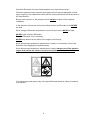
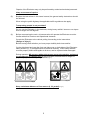
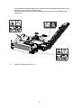
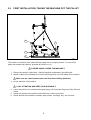
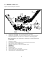
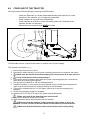
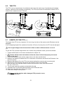
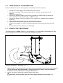
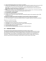
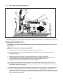
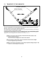
Users manual and
parts book
Eliminator
Serial number:
Translation of the original operating
instructions
ATTENTION:
FOR SAFE USE OF THE MACHINE AND FOR THE BEST RESULTS IT IS VERY
IMPORTANT THAT THIS USER’S MANUAL IS READ METICULOUSLY BEFORE USE OF
THE ELIMINATOR.
0948 English 949.120.200
PREFACE
Congratulations on your Eliminator purchase. For safe and long-lasting operation of this
Eliminator it is necessary to read and understand this user’s manual.
Without full knowledge of the contents it is impossible to work with this machine safely.
The Eliminator is a machine designed for removing infill from artificial turf fields. The Eliminator
has no receiving bin of its own so another machine will have to be used to catch the infill
removed.
The following page deals with the general safety instructions first. Every user must know these
and use them. After this a registration card is entered that needs to be returned in order to be
able to deal with later claims.
In this users’ manual many instructions are given, which are numbered in order. You should act
according to this order. If a
means a tip and/or note.
is used, this points to safety instructions. If a
is used, this
All information and technical specifications provided at the moment that this document is
published are the most recent ones. Design specifications may be changed without prior
notice.
This document is a translation of the original operating instructions.
Upon request, the original operating instructions are available in Dutch.
WARRANTY PROVISIONS
THIS ELIMINATOR IS SUPPLIED WITH A WARRANTY AGAINST DEFECTS IN MATERIALS.
THIS WARRENTY IS VALID FOR A PERIOD OF 12 MONTHS FROM THE PURCHASE DATE.
ELIMINATOR WARRANTIES ARE SUBJECT TO THE “GENERAL CONDITIONS FOR SUPPLY OF
PLANT AND MACHINERY FOR EXPORT, NUMBER 188”, PUBLISHED UNDER THE AUSPICES OF
THE UNITED NATIONS ECONOMIC COMMISSION FOR EUROPE.
REGISTRATION CARD
For your own information, complete the table below:
Serial number machine
Dealer name
Purchase date
Remarks
2
!
Fig. 1
(1)
SAFETY INSTRUCTIONS
!
The Eliminator has been designed to be used
safely. This can only be done if the safety
instructions described in this manual are followed
fully.
Read and understand (Fig. 1) the manual before
you start using the Eliminator.
If the machine is used as described in the manual,
there is the risk of injury and/or damage to the
Eliminator.
When using the machine the operator must be competent and must have
competently adjusted the machine to the surface to be treated.
With incompetent usage and damage resulting from it the manufacturer will not
accept any responsibility; all risks associated with this are the sole responsibility of
the user.
Incompetent usage also includes not following the manufacturer’s directions for use,
maintenance or repairs.
Before using the Eliminator, first inspect the area to be treated.
Remove loose obstacles and avoid irregularities.
(2)
The Eliminator has been manufactured according to the latest technological insights
and is safe for use.
Should the machine be used, maintained or repaired by inexpert persons, then there
is a risk of injury to both the user and third parties. This must be avoided!
(3)
All persons that have been designated by the owner to operate, maintain or repair the
Eliminator, must have read and fully understood the users’ manual and especially the
chapter Safety instructions.
The operator is responsible for the safe usage of the Eliminator.
(4)
The operator is required to check for visible damage and defects before he/she
starts using the Eliminator. Alterations to the Eliminator (including its operation) that
influence the safety negatively must be remedied immediately.
Making alterations or additions to the Eliminator (excluding those approved by the
manufacturer) are not permitted, in principle, for safety reasons.
If modifications to the Eliminator have been made, then the current CE mark is
cancelled and whoever made these modifications must apply for a new CE mark
himself.
3
Check the Eliminator for loose bolts/nuts/parts every time before using it.
Check the hydraulic hoses regularly and replace them if they are damaged or show
signs of ageing. The replacement hoses should comply with the technical demands of
the manufacturer.
Before work is done to it, the pressure should always be taken off the hydraulic
installation.
In the absence of protective covers and safety stickers the Eliminator must NEVER
be used.
When using the Eliminator all protective covers for the machine MUST be fitted.
NEVER crawl under the Eliminator.
Turn the Eliminator over if necessary.
NEVER step down from the tractor if the engine is still turning.
When performing maintenance, adjustments or repairs it is necessary to block the
Eliminator from sagging/moving/sliding away.
When performing maintenance, adjustments or repairs always turn off the tractor’s
engine and remove the tractor’s key from the ignition and disconnect PTO (Fig.2)
Fig. 2
For maintenance and repairs only use original Eliminator parts for safety of machine
and operator.
4
Repairs of the Eliminator may only be performed by authorised technical personnel.
Keep an account of repairs.
(5)
Besides the instructions in this users' manual, the general safety instructions should
be followed.
When using the public highway the applicable traffic regulations also apply.
Transporting people is not permitted!
Do not use the Eliminator in the darkness, during heavy rainfall / storms or on slopes
with an angle over 20 degrees.
(6)
Before commencing the work, all persons who will operate the Eliminator must be
familiar with all its functions and operational elements.
Couple the Eliminator to the vehicle pulling it according to the instructions.
(Danger of injury!)
Before leaving check whether you have proper visibility both close and far.
On the side-board and near the front and side-cover on both sides of the Eliminator
safety stickers (Fig. 5) are applied with an identical meaning. These safety stickers
must be properly visible and legible at all times, and be replaced when damaged.
During operation NO persons without the proper personal protective equipment
are permitted in the danger area of the Eliminator, because there is danger of
physical injury there from spurting material (Fig. 3).
Fig. 4
Fig. 3
Keep a minimum distance of four metres (4 1/3 yards)! (Fig. 4)
5
Wear functional clothes. Wear heavy shoes with steel toecaps, long trousers, long
hair done up and no loose-fitting clothes.
Use the proper personal protective equipment according to the applicable safety
instructions.
Fig. 5
(7)
Position of safety stickers. (Fig. 5)
6
TABLE OF CONTENTS
PREFACE................................................................................................................................... 2
WARRANTY PROVISIONS ........................................................................................................ 2
REGISTRATION CARD.............................................................................................................. 2
! SAFETY INSTRUCTIONS
! ............................................................................................ 3
1.0
TECHNICAL DATA ......................................................................................................... 8
2.0
FIRST INSTALLATION, TAKING THE MACHINE OFF THE PALLET ............................. 9
3.0
GENERAL PARTS LIST.................................................................................................10
4.0
COUPLING TO THE TRACTOR ....................................................................................11
5.0
THE PTO .......................................................................................................................12
5.1
LENGTH OF THE PTO ..................................................................................................12
5.2
USE OF THE PTO .........................................................................................................13
5.3
PTO INFORMATION AND MAINTENANCE...................................................................13
6.0
OPERATION OF THE ELIMINATOR .............................................................................14
6.1
START/STOP PROCEDURE .........................................................................................14
6.2
DRIVING SPEED ...........................................................................................................15
6.3
SETTING WORKING DEPTH ........................................................................................16
6.4
ADJUSTING V-STRING TENSION ................................................................................17
7.0
TRANSPORTING THE ELIMINATOR ............................................................................18
8.0
MAINTENANCE .............................................................................................................19
9.0
PROBLEM ANALYSES..................................................................................................20
10.0 EU STATEMENT ...........................................................................................................20
7
1.0
TECHNICAL DATA
Model
Eliminator
Working width
1500 mm
Working depth (With brush not worn out) 0mm - 40mm (0”-1.5”)
Driving speed
Weight
0 - 5 Km/h
0 - 3 mph
600 Kg (1320 lbs)
Recommended tractor
35 HP. Lifting capacity 900 kg (1984 lbs).
Maximum capacity
7500 m2/h (80730 ft2/h)
(Theoretically at maximum speed; 5 Km/h
(3mph))
Shipping dimensions
LxWxH
1625 x 2120 x 2120 mm
64” x 83.5” x 83.5”
Three-point connection
Oil gear box
CAT. 1 / 2
SAE 30
Standard parts
Frame with aft roller adjustable in height.
Discharge belt, Supply belt, Boom cylinder, Users manual
container with tools.
8
2.0
FIRST INSTALLATION, TAKING THE MACHINE OFF THE PALLET
2
3
1
4
Fig. 6
The machine is delivered on a pallet with the supply belt in transport position. To remove the
pallet and prepare the machine, proceed as follows (see fig.6):
!! NEVER CRAWL UNDER THE MACHINE !!
1. Remove the bottom 3-point pins 1 that the machine is attached to the pallet with.
2. Attach a cable to the forestay pin 2 and to the lifting points 3 on both sides of the machine.
Make sure the cable/crane/elevator can lift at least 1000 kg (2200 lbs).
3. Lift the machine off the pallet 4.
!! PAY ATTENTION AND KEEP YOUR DISTANCE !!
4. Lower the machine in a controlled and gentle way until it touches the ground fully with both
rollers.
5. Check the machine for possible loose bolts/nuts or other loose parts.
6. Check whether the machine’s hydraulic parts (hoses, couplings, etc.) are not loose.
9
3.0
GENERAL PARTS LIST
In figure 8 some important parts are shown:
10
5
9
8
12
6
1
3
7 11
4
2 10
13
1
Fig. 7
1.
2.
Safety sticker 900.280.402, read users manual before use/ toolbox.
Safety sticker 933.280.402, for bystanders without personal protective equipment
keep a 4 metre distance from the machine. Watch out for material flying about!
All safety stickers must be attached to the machine at all times and must be
understood.
3.
4.
5.
6.
7.
8.
9.
10.
11.
12.
13.
Sticker serial number.
PTO sticker for indication rotational direction and revolutions per minute.
Main frame with rotating sweeping brush.
Adjustable construction (aft roller) for work depth setting.
Discharge belt.
Supply belt.
Boom cylinder.
Hydraulic engines.
Users’ manual container with tool set.
Opening for transport setting and fixed work setting.
Slotted hole terrain following work setting.
10
4.0
COUPLING TO THE TRACTOR
Check procedure before starting the coupling of the Eliminator.
− Check the Eliminator for visually observable damage and repair this if a safe
operation of the machine can no longer be guaranteed.
− Check whether all nuts and bolts are tightened.
− Check whether all protective covers and safety stickers are attached to the
machine and are not damaged.
Without them the machine must NEVER be used.
4
2
5
3
1
Fig. 9
The Eliminator can be coupled to the tractor by means of the 3-point linkage.
The method is as follows: (Fig. 9)
1. Remove the 3-point pins 1 and 2
2. Reverse the tractor carefully, so the lower connecting arms can be coupled to the frame.
3.
!! Make sure the tractor is blocked properly and cannot move of its own accord !!
4.
!! Turn off the tractor before dismounting !!
5. Connect the lower connecting arms with the 3-point connecting plate pins 1 and secure
these with the retaining pins supplied.
6. Set the tractor’s stabiliser to 100 mm sideways stroke
7. Install the forestay on your tractor and unscrew this until it is at the same height as the
upper 3-point top connection 3 (transport setting) of the Eliminator.
8. Connect the forestay with pin 2 on the frame; secure pin 2 with the retaining pin 3
supplied.
9. Screw in the forestay so that it is charged.
10. Install the PTO 5 to the PTO-axis of the tractor and the Eliminator.
!! Make sure that all the fastening pins are secured!!
11. Connect the hydraulic hoses to the tractor.
12. Start the tractor and lift the Eliminator from the surface.
!! Make sure that the machine is lifted parallel to the surface as much as
possible. For this use one of the three holes on the lowest 3-point connection.
!! Make sure that the Eliminator does not touch the tractor during lifting.
11
5.0
THE PTO
Max.
30°
The PTO is a very important part. It provides the drive from the tractor and, if maintained and installed
properly, makes sure the machine is used safely. The PTO has its own CE-certification. Read the PTO
manual; this is attached to the PTO itself.
Ma
x. 3
0°
A
B
150 mm
(6") min
.
Fig. 8
5.1
LENGTH OF THE PTO (fig. 8)
The length of the PTO is very important. If it is too long, the drive of the tractor and/or Eliminator can be
damaged.
If the overlapping length of the cylinders is less than 150 mm (6”) at any time, the PTO can be damaged.
!! The length changes when the machine is lifted or when a different tractor is used !!
To give the PTO its proper length when new or when using a different tractor, proceed as follows:
1. Couple the Eliminator to the tractor as described in chapter 5.0.
2.
!! Switch off the tractor and make sure that the tractor is blocked properly and cannot
move on its own !!
3. Lower the Eliminator to the surface until it rests on the front and aft rollers.
4. Measure the distance A between the PTO connection of the tractor and that of the Eliminator, from
groove to groove.
5. Measure the distance B on the PTO in its shortest setting from securing pin to securing bolt.
6. Split the PTO into two parts and remove the protective cover from both ends.
7. Both the ends of the cylinders and the ends of the protective covers must be shortened:
(B - A) + 75 mm (3”).
8. Trim all parts; use some grease and assemble all parts.
9. Assemble the PTO with the break bolt safety on the Eliminator side.
10. Attach the other side of the PTO to the tractor.
11. Check the overlap of the cylinders.
!! Never use the machine with a damaged PTO protective cover;
Replace this first !!
12
5.2
USE OF THE PTO
For proper use of the PTO the following items must be checked:
1. During operation of the Eliminator the angle of the turning points must never exceed 30
degrees.
2. The turning points must always be in line.
3. The overlap of the cylinders must always be at least 150 mm.
4. Never use the machine with a damaged PTO protective cover.
5.3
PTO INFORMATON AND MAINTENANCE
Concise maintenance schedule PTO.
Periodical maintenance:
−
−
−
Grease the greasing points after every 100 hours of operation or after the PTO has been
idle for a long time.
Check the PTO for damage to the protective covers and replace them if they are no
longer satisfactory.
Check whether the safety stickers are still present and undamaged on the PTO.
Annual maintenance:
−
−
−
−
−
−
−
−
Remove the PTO from the machine.
Inspect the PTO parts.
All damaged parts need to be replaced.
Put all parts down and examine them meticulously.
If any parts are damaged or worn out, replace them.
Clean all interlocking parts.
Reassemble all parts.
Grease both cylinders and reassemble both PTO parts.
Assemble the PTO and fit it to the machine.
For further information on the maintenance and disassembly of the PTO, see the
manual included with the PTO.
If the PTO was shortened incorrectly or if another tractor is used, the gear box can
be over-burdened. Damage can be done to the tractor and the Eliminator!
13
6.0
OPERATION OF THE ELIMINATOR
Before the Eliminator can be used anywhere, the following should be checked:
1. Are there any loose objects on the field? Remove these first.
2. Are there any slopes? The maximum slope that this machine can be used on is 20
degrees.
Always work downward.
3. Is there any danger of objects flying around, like balls for instance that can distract the
driver’s attention? If so, the Eliminator can NOT be used.
4. Is there any danger of sinking or slipping? If so, postpone the treatment until conditions
are better.
5. If the ground is wet, postpone the work until conditions are better.
6. If the machine vibrates too vigorously, go back in PTO speed.
7. A field can be treated 2 or 3 times in the same direction to get a thorough removal of the
infill.
8. Do not make turns; the subsoil can be damaged.
6.1
START/STOP PROCEDURE
The start procedure is VERY important. If this procedure is not conducted as described below, then
serious damage can be done to the surface to be treated/the machine.
1
4
2
3
Fig. 10
Thee start procedure is as follows: (see Fig. 10)
1. Check the Eliminator thoroughly for loose parts and check whether all parts are functioning properly.
!! If loose parts have been found or if parts do not work properly, then the problems
need to be solved first before using the Eliminator !!
2. Drive to the location where the treatment needs to take place.
!! Attention, the supply belt must be in the transport position! (See chapter. 7.0)
14
3. Lower the Eliminator gently to the surface to be treated.
4. Make sure the adjustable aft roller is all the way out or at least far enough so that not too much infill
is removed from the turf by the brush right away. For the depth adjustment see chapter 6.3.
!! Make sure that the tractor is blocked properly and cannot move of its own accord !!
!! Switch off the tractor before getting off !!
5. If desired the forestay 1 can be fitted into the terrain following setting in slot 4. Do this by loosening
the retaining pin 3 and forestay pin 4 and fitting them back in slot 4.
6. Set supply belt in working position.
7. Put the tractor in the right gear.
8. Engage the hydraulically driven conveyor belts.
9. Engage the PTO with a low engine speed and increase this gently to the maximum value of 540
revolutions/ minute
10. Now drive forward and increase the speed to, at most, 5 Km/h (3 mph). See chapter 6.2.
11. Make sure the Eliminator moves at a speed equal to that of the external receiving bin.
12. If the desired depth is not achieved, adjust the brush to a greater depth and restart the treatment.
Stopping is conducted as follows:
1.
2.
3.
4.
5.
6.
Bring the tractor to a standstill.
Disengage the PTO so the brush is brought to a standstill.
Disengage the conveyor belts as soon as no infill is removed anymore.
Place the supply belt in the transport position.
Lift the Eliminator off the ground.
Drive to the next location and start the treatment as discussed above.
6.2
DRIVING SPEED
The maximum driving speed during the treatment is limited to 5 km/h (3 mph).
The optimal driving speed is determined by the amount of infill material to be removed. As more
infill material is to be removed, the driving speed needs to be lowered to arrive at a good result.
So this depends on the condition of the artificial turf and can therefore not be expressed in a
fixed value. The abovementioned recommended maximum speed is a safety value to prevent
excessive wear and tear and damage to both machine and the surface to be treated.
15
6.3
SETTING WORKING DEPTH
2
1
3
40 mm / 1.5 In
Min.
Max.
Fig. 11
The working depth of the brush can be adjusted by adjusting the aft roller. This is done by turning the
spindles at the back of the machine.
The procedure is as follows: (see fig.11)
!! Make sure that the tractor/Eliminator is blocked properly and cannot move of its own
accord !!
!! Switch off the tractor before getting off !!
1. Loosen the nuts 1 on both sides of the machine a couple of turns.
A set of spanners has been supplied with the machine; these are in the manual/tool set
container (see fig.7).
2. Adjust the spindles 2 and thus the working depth with the spanners supplied.
3. Set both sides of the machine at equal height. This way an equal amount of infill material
is removed over the full working width. Use the indication stickers 3 for this.
4. Retighten the bolts 1 on both sides of the machine properly.
As artificial turf fields differ from each other a lot, the desired working depth will have to be
found empirically. The given maximum working depth of 40 mm is a theoretical value and no
doubt will be different in practice.
It may be that the infill material is compacted too tightly so not enough of it is removed and the
desired working depth can therefore not be achieved in one go. Applying the treatment a
second or third time can then ensure that the final desired working depth is achieved. If the infill
material turns out to be too tightly compacted after all, make sure the infill material is loosened
before starting the treatment.
16
6.4
ADJUSTING V-STRING TENSION
1
2
3
4
A
5
6
Fig. 12
The Eliminator is equipped with a standard adjustable tensioning roller that keeps the v-strings
under tension.
As the machine is used, wear and tear occurs on the drive line.
Because of this it may occur that the v-strings start to slip and must be retensioned.
Adjusting the tensioning roller is done as follows (See Fig 12):
!! Make sure that the tractor is blocked properly and cannot move of its own accord !!
!! Make sure that the Eliminator’s PTO-axle has been uncoupled !!
1. Remove all nuts 1 and safety cover 2.
2. Loosen nut 3.
3. Loosen nut 4 a couple of turns depending on how much the v-string 6 needs to be
tightened
4. Adjust the v-string’s tension using nut 5.
5. Check the v-string tension by pulling point A with a force of 3.8 kg (8.4lbs). The play
should be 9 mm (0.35”).
6. Tighten nut 4 again.
7. Tighten nut 3.
8. Replace protective cover 2 and install all nuts 1.
17
7.0
TRANSPORT OF THE ELIMINATOR
Transport position
Work Position
Fig. 13
The user is responsible for the transportation of the Eliminator behind the tractor on the public
highways. Check the national laws regarding regulations.
Over open fields, with the machine lifted, the speed must not exceed a maximum of 20 km/hour
(12.4 mph), because of the Eliminator’s weight.
A higher speed can be dangerous for the driver/bystanders and may even damage the machine.
To transport the machine it must first be put in transport position. This is done by folding up the
supply belt so that it hangs above the machine in its entirety. (see fig. 13)
Make sure that the upper forestay is connected and under tension in the
transport position! See fig. 7
If not, then serious damage can be done to the machine.
If the machine is lifted off the ground, at least 20% of the tractor’s weight
must be supported by the front axle.
Make sure that the supply belt is in the transport position during transport. This
is done to avoid damage to the machine.
18
8.0
MAINTENANCE
Time-line
Before every use.
Check point/Greasing
point
Check for loose bolts / nuts.
Presence and Legibility of safety
stickers. (Fig. 7)
Check for hydraulic defects.
After first 20 working hours
(new or repaired).
Check the roller bearings and the
drive line.
Check for loose bolts / nuts.
After every 40 working
hours or annually.
Check the tension of the vstrings.
Check the roller bearings and the
drive line.
Check the bearing houses.
Check for loose bolts / nuts.
Check the tension / wear and tear
of the v-strings.
Check the wear and tear of the
brush.
Check gear box for oil leakage.
Check oil level in gear box.
Check for hydraulic defects.
Check PTO.
Check tension conveyor belts.
After every 500 hours.
Replace oil gear box.
19
Method
Tighten the loose bolts/nuts
with the right torque
Replace these if not
present/damaged.
If necessary, repair or replace
damaged parts.
If necessary grease roller
bearings / If necessary,
replace worn parts. Use EP 2
lubrication grease.
Tighten the loose bolts/nuts
with the right torque
If necessary adjust the tension
of the v-strings. (see hfst 6.4)
If necessary grease roller
bearings / If necessary,
replace worn parts. Use EP 2
lubrication grease.
Lubricate bearing houses / If
necessary, replace worn parts.
Tighten the loose bolts/nuts
with the right torque
Adjust the tension of the vstrings. (see chap. 6.4)
If necessary, replace v-strings.
If necessary, replace brush.
Repair or replace.
If necessary, refill to edge
filling opening.
If necessary, repair or replace
damaged parts.
Lubricate PTO or if necessary,
replace PTO.
If necessary, increase tension
of conveyor belts.
Remove old oil and fill with
new oil to edge filling opening.
1.
9.0
PROBLEM ANALYSES
Problem
Not enough infill material is
removed.
The brush is not turning or
not properly.
The conveyor belts cannot
handle the amount of infill
material removed.
Possible Cause
The brush is not set deep
enough.
Infill material is too tightly
compacted.
Driving speed is too high.
Material too wet.
The v-strings driving the
brush are slipping.
Machine is set too deep.
Driving speed is too high.
Conveyor belts are turning
too slowly.
Solution
Increase the depth by adjusting
the aft roller.
Loosen the infill material.
Reduce driving speed.
Wait for better circumstances.
Tighten the v-strings as described
in chapter 6.4
Reduce the machine’s depth.
Reduce driving speed.
Increase oil flow so conveyor
belts speed up.
10.0 EU STATEMENT
We, Redexim BV, Utrechtseweg 127, 3702 AC Zeist, The Netherlands, state under our own
responsibility that the product:
ELIMINATOR WITH MACHINE NUMBER AS INDICATED ON THE MACHINE AND IN THIS
MANUAL,
to which this declaration relates is according to the stipulation of the 2006/42/EC directive for
machines.
Zeist, 01/10/09
A.C. Bos
Manager Operations & Logistics
Redexim Holland
20