1
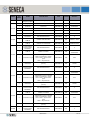
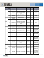
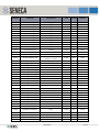
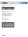
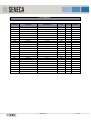
ZC-24DI
CANopen TPDOs TRANSMISSION
CANopen/Modbus
I/O Module
24 Digital Input
Or
16 Digital input and
8
Counters (32 bit)
TYPE SUPPORTED
User Manual
OBJECT VALUE
0x180x sub 2
TRANSMISSION TYPE
0
Synchronous - acyclic
From 1 to 240
Synchronous - cyclic
255
Asynchronous
Contents:
CANopen Features
CANopen PDOs
CANopen PDO Transmission
Type
CANopen Emergency
Message
CANopen Functional
Diagrams
CANopen Object Dictionary
CANopen PDOs MAPPING
OBJECTS FOR DEFAULT MAPPING
PDO NR
Modbus Features
Modbus Register
Modbus Command
TDO1
COB-ID
0x40000180
+
NodeId
CANopen FEATURES
TPDO 5
TECHNICAL DATA
BAUD RATE
20, 50, 125, 250, 500, 800,
1000 Kbits/s
COUNTERS NR/TYPE
8 (32 bit) from input 1..8
MAX FREQUENCY FOR
COUNTERS
10 kHz
TYPICAL ON/OFF DELAY
1 ms (with filter disabled)
TPDO 6
TPDO 7
CANOpen TECHNICAL DATA
NMT
SLAVE
ERROR CONTROL
NODE GUARDING
NODE ID
HW SWITCH OR SOFTWARE
TPDO 8
NUMBER OF PDO
5 TX
PDO MODES
Event Triggered, Sync (cyclic),
Sync (acyclic)
PDO MAPPING
VARIABLE
PDO LINKING
SUPPORTED
NUMBER OF SDO
1 SERVER
ERROR MESSAGE
YES
SUPPORTED APPLICATION
CiA 301 v4.02
LAYER
CiA 401 v2.01
MI001674-E
0x40000280
+
NodeId
0x40000380
+
NodeId
0x40000480
+
NodeId
0x40000300
+
NodeId
MAPPED
OBJECTS
Digital
Input
[1..8]
Digital
Input
[9..16]
Digital
Input
[17..24]
Overflow
counter
[1..8]
Counter 1
value
Counter 2
value
Counter 3
value
Counter 4
value
Counter 5
value
Counter 6
value
Counter 7
value
Counter 8
value
INDEX
SUBINDEX
0x6000
1
0x6000
2
0x6000
3
0x6000
4
0x2210
1
0x2210
2
0x2210
3
0x2210
4
0x2210
5
0x2210
6
0x2210
7
0x2210
8
Note that TPDO COB-ID must starts with 0x4
1 of 18
If Hardware switches are in “from memory” mode baud
rate is selectable by Object 0x2002.
CANopen EMERGENCY MESSAGE
The Emergency message is composed by:
2 bytes of EEC (Emergency error code)
1 bytes of ER (Error Register)
4 bytes MEF (Manufacturer Error Filled Objects
(0x1200)
BAUDRATE ( OBJECT 0X2002)
EMERGENCY MESSAGE
BYTE0
BYTE1
BYTE2
EER
BYTE3
BYTE4
ER
BYTE5
BYTE6
MEF
OBJECT VALUE
DESCRIPTION
1
20 Kbit/s
2
50 Kbit/s
3
125 Kbit/s
4
250 Kbit/s
5
500 Kbit/s
6
800 Kbit/s
7
1 Mbit/s
EEC
CODE
DESCRIPTION
0x0000
No Error
Object 0x2030 can be used for monitoring the CPU
temperature
0x1000
Generic error
0x4201
CPU Temperature over T_HIGH_HIGH
CPU TEMPERATURE ( OBJECT 0X2030 )
0x4202
CPU Temperature over T_HIGH
0x4203
CPU Temperature under T_LOW
SUBINDEX
0x8110
Communication Can Overrun
1
0x8120
Error Passive
0x8130
Life Guard Error
0x8140
Recovered From Bus Off
0xFF20
CPU Error
2
3
4
ER
BIT7 BIT6 BIT5
Generic
0
0
BIT4
BIT3
BIT2 BIT1
Temperature Communication
0
0
BIT0
Manifacture
DESCRIPTION
Actual Temperature [°C/10]
Temperature for HOT STOP
ERROR [°C/10] 95.0°
Temperature for HOT ERROR
[°C/10] 90.0°
Temperature for COLD ERROR
[°C/10] -25.0°
The HOT STOP Temperature sends in preoperational the station.
The HOT ERROR and the COLD ERROR Temperature
sends the Emergency Object.
The Object is Read Only
Where if the bit is 0 means no error
CANopen MANUFACTURER SPECIFIC
PROFILE
Object 0X2051 is used to send commands to the
station module.
CPU COMMAND (OBJECT 0X2051)
If Hardware switches are in “from memory” mode the
node address is selectable by Object 0x2001.
NODE ADDRESS (OBJECT 0X2001:)
OBJECT VALUE
DESCRIPTION
0….127
Node Address
MI001674-E
COMMAND CODE
DESCRIPTION
0x5C0n
Force the preset value (object
0x2211) for counter n
0x5D0n
Force the reset for counter n
0x5E0n
Force the overflow reset (object
0x6000 sub 4)
2 of 18
Object 0X2200 is used to customize the input filter.
DIP-SWITCH CONFIGURATION
FILTER PARAMETERS (OBJECT 0X2200)
SUBINDEX
1
2
3
DESCRIPTION
Samples Number for filter
(default 40)
Counter threshold for high level
(default 20)
Counter threshold for low level
(default 20)
For a high level sample the filter counter is
incremented, otherwise for a low level the filter
counter is decremented.
When the filter counter is greater or equal subindex2
the input is stated “high”.
When the filter counter is lower or equal subindex3
the input is stated “low”.
In beetween subindex2 and subindex3 no state is
asserted (dead zone).
Note that the filter can be disabled by
selecting:
Subindex 1 = 1
Subindex 2 = 0
Subindex 3 = 0
CANopen LED DESCRIPTION
SERVICE (DIAGNOSTIC) LED DESCRIPTION
LED
RUN
Object 0x2210 stores the values of the 8 counters in
32 bit format.
STATE
DESCRIPTION
BLINKING
Pre-operational
mode
SINGLE FLASH
Stop mode
ON
Operational mode
At least one error
counter has
reached or
exceeded the
warning level
ERROR
DIGITAL COUNTERS ( OBJECT 0X2210)
SINGLE FLASH
SUBINDEX
DESCRIPTION
1
Preset Counter 1 Value
2
Preset Counter 2 Value
3
Preset Counter 3 Value
4
Preset Counter 4 Value
5
Preset Counter 5 Value
6
Preset Counter 6 Value
7
Preset Counter 7 Value
DOUBLE FLASH
TRIPLE FLASH
ON
OFF
FAIL
POWER
ON BLINKING
GUARD Event
The SYNC hasn’t
received within the
configurated
communication
cycle timeout
period
The CAN controller
is bus OFF
NO Error
Data receiving from
RS232
ON
Power Supply
INPUT LED DESCRIPTION
LED
1…8
9….24
MI001674-E
STATE
DESCRIPTION
ON
Input [1..8] is high
OFF
Input [1..8] is low
ON
Input [9..24] is high
OFF
Input [9..24] is low
3 of 18
CANopen DIGITAL INPUT MANAGEMENT
Object 0x6008 is used as Digital Interrupt Mask High
to Low.
Object 0x6003 is used for Input Filter Configuration
IINTERRUPT MASK HIGH TO LOW (OBJECT 0X6008)
SUBINDEX
FILTER CONSTANT INPUT (OBJECT 0X6003)
SUBINDEX
1
2
3
1
DESCRIPTION
2
FILTER ENABLED FOR INPUT
[1..8]
FILTER ENABLED FOR INPUT
[9..16] READ ONLY
FILTER ENABLED FOR INPUT
[17..24] READ ONLY
If the value of object 0x6003 subindex 1 is “0” all inputs
from 1 to 8 are configured in counter mode,in other
word counter mode switched ON.
3
DESCRIPTION
Interrupt mask on falling edsge
input [1..8]
Interrupt mask on falling edsge
input [9..16]
Interrupt mask on falling edsge
input [17..24]
For subindex form 1 to 3 if value is “1” than the
generation of TxPDO on falling edge is enable
If the value of object 0x6003 subindex 1 is not equal
to “0” the counter mode is switched OFF.
Object 0x6005 is used for Interrupt Enable:
If the value is “1” the station can generate a
synchronous TxPDO (DEFAULT setting).
If the value is “0” the station can’t generate a
synchronous TxPDO.
Object 0x6007 is used as Digital Interrupt Mask Low to
Hgh.
IINTERRUPT MASK LOW TO HIGH (OBJECT 0X6007)
SUBINDEX
1
2
3
4
DESCRIPTION
Interrupt mask on rising edge input
[1..8]
Interrupt mask on rising edge input
[9..16]
Interrupt mask on rising edge input
[17..24]
Interrupt mask for counters
overflow
For subindex form 1 to 3 if value is “1” than the
generation of TxPDO on rising edge is enabled.
If subindex 4 value is “1” the generation of TxPDO on
all 8 counters overflows is enabled.
MI001674-E
4 of 18
CANopen FUNCTIONAL DIAGRAM
COUNTER MODE ON (Subindex 1 Object 0x6003 = ‘0’)
MI001674-E
5 of 18
CANopen OBJECT DICTIONARY
Communication Profile Area
INDEX
SUB
INDEX
NAME
DESCRIPTION
TYPE
ACCESS
DEFAULT
0x1000
0
Device Type
Device Type (Profile 401 = 0x191)
UNSIGNED 32
RO
0x10191
0x1001
0
Error register
Error register (DS 401)
UNSIGNED 8
RO
0
0x1002
0
Manufacturer
Status Register
Status Register
UNSIGNED 32
RO
0
0x1005
0
SYNC COB-ID
The device consumes the SYNC
mesage
UNSIGNED 32
RW
0x80
0x1006
0
Communication
Window Length
Sync interval [us]
UNSIGNED 32
RW
0
0x1007
0
Synchronous
Window Length
Time window [us] for the PDO
transmission after the SYNC
UNSIGNED 32
RW
0
0x1008
0
Manufacturer
Device Name
Device name
VISIBLE
STRING
RO
“ZC-24DI”
0x1009
0
Manufacturer
Hardware version
Hardware version
VISIBLE
STRING
RO
“SC000000”
0x100A
0
Manufacturer
Software version
Software version
VISIBLE
STRING
RO
“SW001170”
0x100C
0
Guard Time
Guard Time [ms]
UNSIGNED 16
RW
0
0x100D
0
Life Time Factor
Max delay between two guarding
telegrams =
Guard_Time*Life_Time_Factor
UNSIGNED 8
RW
0
0
Store Parameters
Max Subindex Number
RO
4
1
Save All
Parameters
Store not volatile parameters (Write
in ASCII “save” for store process
MSB 0x65766173 LSB)
UNSIGNED 32
RW
1
2
Save
Communication
Parameters
Store not volatile parameters (Write
in ASCII “save” for store process
MSB 0x65766173 LSB)
UNSIGNED 32
RW
1
3
Save Application
Parameters
Store not volatile parameters
UNSIGNED 32
RW
1
4
Save
Manufactures
Parameters
Store not volatile parameters
UNSIGNED 32
RW
1
0
Restore Default
Max Subindex Number
UNSIGNED 8
RO
4
1
Restore All
Parameters
Restore not volatile parameters
(Write in ASCII “load” for load
process MSB 0x64616F6C LSB)
UNSIGNED 32
RW
0
2
Restore
Communication
Parameters
Restore not volatile parameters
(Write in ASCII “load” for load
process MSB 0x64616F6C LSB)
UNSIGNED 32
RW
0
3
Restore
Application
Parameters
Restore not volatile parameters
(Write in ASCII “load” for load
process MSB 0x64616F6C LSB)
UNSIGNED 32
RW
0
4
Restore
Mnufactures
parameters
Restore not volatile parameters
(Write in ASCII “load” for load
process MSB 0x64616F6C LSB)
UNSIGNED 32
RW
0
0x1010
0x1011
MI001674-E
6 of 18
INDEX
SUB
INDEX
NAME
DESCRIPTION
TYPE
ACCESS
DEFAULT
0x1014
0
COB-ID
Emergency Object
COB-ID for Emergency Object
UNSIGNED 32
RO
NODEID + 0x80
0
Identity Object
Max Subindex Number
UNSIGNED 8
RO
4
1
Vendor ID
Seneca srl
UNSIGNED 32
RO
0x00000249
2
Product Code
ZC-24DI Machine ID Code
UNSIGNED 32
RO
0x00000020
3
Revision Number
Revision
UNSIGNED 32
RO
0
4
Serial Number
Serial Number Code
UNSIGNED 32
RO
0
0
Server SDO
Parameters
Max Subindex Number
UNSIGNED 8
RO
2
1
Receive SDO
COB-ID
COB-ID of Receive SDO
UNSIGNED 32
RO
NODEID + 0x600
2
Transmit SDO
COB-ID
COB-ID of Transmit SDO
UNSIGNED 32
RO
NODEID+0x580
0
Transmit PDO1
Communication
Parameters
Max Subindex Number
UNSIGNED 8
RO
3
1
COB-ID
COB-ID of TxPDO1
UNSIGNED 32
RW
NODEID +
0x40000180
2
Transmission Type
Transmission Type for TxPDO1
0x00 = Synchronous - acyclic
0x01 to 0xF0 = Synchronouscyclic
0xFF = Asynchronous
UNSIGNED 8
RW
0xFF
3
Inhibit Time
Min. delay for the next PDO
(ms/10)
UNSIGNED 16
RW
0x0000
0
Transmit PDO5
Communication
Parameters
Max Subindex Number
UNSIGNED 8
RO
3
1
COB-ID
COB-ID of TxPDO5
UNSIGNED 32
RW
NODEID +
0x40000280
2
Transmission Type
Transmission Type for TxPDO5
0x00 = Synchronous - acyclic
0x01 to 0xF0 = Synchronouscyclic
0xFF = Asynchronous
UNSIGNED 8
RW
0x01
3
Inhibit Time
Min. delay for the next PDO
(ms/10)
UNSIGNED 16
RW
0x0000
0
Transmit PDO6
Communication
Parameters
Max Subindex Number
UNSIGNED 8
RO
3
1
COB-ID
COB-ID of TxPDO6
UNSIGNED 32
RW
NODEID +
0x40000380
2
Transmission Type
Transmission Type for TxPDO6
0x00 = Synchronous - acyclic
0x01 to 0xF0 = Synchronouscyclic
0xFF = Asynchronous
UNSIGNED 8
RW
0x01
3
Inhibit Time
Min. delay for the next PDO
(ms/10)
UNSIGNED 16
RW
0x0000
0
Transmit PDO7
Communication
Parameters
Max Subindex Number
UNSIGNED 8
RO
3
0x1018
0x1200
0x1800
0x1804
0x1805
0x1806
MI001674-E
7 of 18
INDEX
SUB
INDEX
NAME
DESCRIPTION
TYPE
ACCESS
DEFAULT
1
COB-ID
COB-ID of TxPDO7
UNSIGNED 32
RW
NODEID +
0x40000480
2
Transmission Type
Transmission Type for TxPDO7
0x00 = Synchronous - acyclic
0x01 to 0xF0 = Synchronouscyclic
0xFF = Asynchronous
UNSIGNED 8
RW
0x01
3
Inhibit Time
Min. delay for the next PDO
(ms/10)
UNSIGNED 16
RW
0x0000
0
Transmit PDO1
Communication
Parameters
Max Subindex Number
UNSIGNED 8
RO
3
1
COB-ID
COB-ID of TxPDO1
UNSIGNED 32
RW
NODEID +
0x40000300
2
Transmission Type
Transmission Type for TxPDO1
0x00 = Synchronous - acyclic
0x01 to 0xF0 = Synchronouscyclic
0xFF = Asynchronous
UNSIGNED 8
RW
0x01
3
Inhibit Time
Min. delay for the next PDO
(ms/10)
UNSIGNED 16
RW
0x0000
0
Transmit PDO1
Mapping
Max Subindex Number
UNSIGNED 8
RO
4
1
Object NR1
First Object (default: Input 1..8)
UNSIGNED 32
RW
0x60000108
Object = 0x6000
Subindex = 1
Length = 8 bit
0x1807
2
Object NR2
Second Object (default: Input 9..16)
UNSIGNED 32
RW
0x60000208
Object = 0x6000
Subindex = 2
Length = 8 bit
3
Object NR3
Third Object (default: Input 17..24)
UNSIGNED 32
RW
0x60000308
Object = 0x6000
Subindex = 3
Length = 8 bit
4
Object NR4
Fourth Object (default: Counter
Overflow)
UNSIGNED 32
RW
0x60000408
Object = 0x6000
Subindex = 4
Length = 8 bit
0
Transmit PDO5
Mapping
Max Subindex Number
UNSIGNED 8
RO
2
1
Object NR1
First Object (default:: Counter 1)
UNSIGNED 32
RW
0x22100120
Object = 0x2210
Subindex = 1
Length = 32 bit
RW
0x22100220
Object = 0x2210
Subindex = 2
Length = 32 bit
0x1A00
0x1A04
2
Object NR2
Second Object (default: Counter2)
MI001674-E
UNSIGNED 32
8 of 18
INDEX
SUB
INDEX
NAME
DESCRIPTION
TYPE
ACCESS
DEFAULT
0
Transmit PDO6
Mapping
Max Subindex Number
UNSIGNED 8
RO
2
1
Object NR1
First Object (default:: Counter 3)
UNSIGNED 32
RW
0x22100320
Object = 0x2210
Subindex = 3
Length = 32 bit
2
Object NR2
Second Object (default:: Counter 4)
UNSIGNED 32
RW
0x22100420
Object = 0x2210
Subindex = 4
Length = 32 bit
0
Transmit PDO7
Mapping
Max Subindex Number
UNSIGNED 8
RO
2
1
Object NR1
First Object (default: Counter 5)
UNSIGNED 32
RW
0x22100520
Object = 0x2210
Subindex = 5
Length = 32 bit
0x1A05
0x1A06
2
Object NR2
Second Object (default: Counter 6)
UNSIGNED 32
RW
0x22100620
Object = 0x2210
Subindex = 6
Length = 32 bit
0
Transmit PDO8
Mapping
Max Subindex Number
UNSIGNED 8
RO
2
1
Object NR1
First Object (default:: Counter 7)
UNSIGNED 32
RW
0x22100720
Object = 0x2210
Subindex = 7
Length = 32 bit
0x1A07
2
Object NR2
Second Object (default: Counter 8)
UNSIGNED 32
RW
0x22100820
Object = 0x2210
Subindex = 8
Length = 32 bit
0
Transmit PDO7
Mapping
Max Subindex Number
UNSIGNED 8
RO
2
1
Object NR1
First Object (default: Counter 5)
UNSIGNED 32
RW
0x22100520
Object = 0x2210
Subindex = 5
Length = 32 bit
RW
0x22100620
Object = 0x2210
Subindex = 6
Length = 32 bit
0x1A06
2
Object NR2
Second Object (default: Counter 6)
MI001674-E
UNSIGNED 32
9 of 18
Manufacturer Profile Area
INDEX
SUB
INDEX
NAME
DESCRIPTION
TYPE
ACCESS
DEFAULT
0x2001
0
Module Address
Station Address
(only if dip switch 4,5,6,7,8,9,10
are OFF)
UNSIGNED 8
RW
127
0
Buad Rate
Station Baud Rate
(only if dip switch 1,2,3 are OFF)
1 = 20Kbps
2 = 50Kbps
3 = 125Kbps
4 = 250Kbps
5 = 500Kbps
6 = 800Kbps
7 = 1Mbps
UNSIGNED 8
RW
7
0
Device
Temperature
Max Subindex Number
UNSIGNED 8
RO
4
1
Internal
Temperature
Station internal Temperature
[°C/10]
INTEGER 16
RO
0
2
Hi Hi Temperature
Critical Hot Temperature
(All operations Stop )
[°C/10
INTEGER 16
RO
950
3
Hi Temperature
Warning for Too Hot
Temperature
[°C/10]
INTEGER 16
RO
900
4
Low Temperature
Critical Low Temperature
(All operations Stop )
[°C/10]
INTEGER 16
RO
-250
UNSIGNED 16
RW
0
0x2002
0X2030
0x2051
0
CPU Command
Command to execute
Supported commands are:
0x5Cnn Force preset for counter
mask nn
0x5Dnn Force reset for counter
mask nn
0x5Enn Force overflow for counter
mask nn
0x2052
0
Aux Command
Reserved
UNSIGNED 16
RW
0
0
Input Filter
Parameter
Max Subindex Number
UNSIGNED 8
RO
3
1
Filter Length
Number of samples to evaluate
UNSIGNED 8
RW
40
2
Counter threshold
for high level
If counter >= threshold_high input
is stated “high”
UNSIGNED 8
RW
20
3
Counter threshold
for low level
If counter <= threshold_low input is
stated “low”
UNSIGNED 8
RW
20
0
Input Counters
Max Subindex Number
UNSIGNED 8
RO
8
1
Counter 1 Value
Counter 1 value
UNSIGNED 32
RW
0
2
Counter 2 Value
Counter 2 value
UNSIGNED 32
RW
0
3
Counter 3 Value
Counter 3 value
UNSIGNED 32
RW
0
4
Counter 4 Value
Counter 4 value
UNSIGNED 32
RW
0
0x2200
0x2210
MI001674-E
10 of 18
INDEX
0x2211
SUB
INDEX
NAME
DESCRIPTION
TYPE
ACCESS
DEFAULT
5
Counter 5 Value
Counter 5 value
UNSIGNED 32
RW
0
6
Counter 6 Value
Counter 6 value
UNSIGNED 32
RW
0
7
Counter 7 Value
Counter 7 value
UNSIGNED 32
RW
0
8
Counter 8 Value
Counter 8 value
UNSIGNED 32
RW
0
0
Preset for Input
Counters
Max Subindex Number
UNSIGNED 8
RO
8
1
Counter 1 Preset
Value
Counter 1 preset value
UNSIGNED 32
RW
0
2
Counter 2 Preset
Value
Counter 1 preset value
UNSIGNED 32
RW
0
3
Counter 3 Preset
Value
Counter 1 preset value
UNSIGNED 32
RW
0
4
Counter 4 Preset
Value
Counter 1 preset value
UNSIGNED 32
RW
0
5
Counter 5 Preset
Value
Counter 1 preset value
UNSIGNED 32
RW
0
6
Counter 6 Preset
Value
Counter 1 preset value
UNSIGNED 32
RW
0
7
Counter 7 Preset
Value
Counter 1 preset value
UNSIGNED 32
RW
0
8
Counter 8 Preset
Value
Counter 1 preset value
UNSIGNED 32
RW
0
Standard Device Profile Area
INDEX
0x6000
SUB
INDEX
NAME
DESCRIPTION
TYPE
ACCESS
DEFAULT
0
8 bit Digital Input
Counter 1 overflow
Max Subindex Number
UNSIGNED 8
RO
4
1
Input [1..8] Value
Read input [1..8] value
UNSIGNED 8
RO
0
2
Input [9..16] Value
Read input [9..16] value
UNSIGNED 8
RO
0
3
Input [17..24] Value
Read input [17..24] value
UNSIGNED 8
RO
0
4
Counter [1..8]
overflow
Overflow Status Counter [1..8]
UNSIGNED 8
RO
0
0
Filter Mask Enable
Max Subindex Number
UNSIGNED 8
RO
3
1
Input [1..8] Filter
Mask Enable
Input [1..8] Filter enable
Mask bit 0 = Filter disabled
(and Counters 1..8 Enabled)
Mask bit 1 = Filter enabled
(and Counters 1..8 Disabled)
UNSIGNED 8
RW
0XFF
2
Input [9..16] Filter
Mask Enable
Input [9..16] Filter Mask enable
UNSIGNED 8
RO
0xFF
3
Input [17..24] Filter
Mask Enable
Input [17..24] Filter Mask enable
UNSIGNED 8
RO
0xFF
0x6003
MI001674-E
11 of 18
INDEX
SUB
INDEX
NAME
DESCRIPTION
TYPE
ACCESS
DEFAULT
0x6005
0
Global Interrupt
Enabled
0 = TxPDO Asynchronous disabled
1 = TxPDO Asynchronous enabled
UNSIGNED 8
RW
1
0
Interrupt Mask Low
to High
Max Subindex Number
UNSIGNED 8
RO
4
1
Input [1..8]
interrupt Low to
High mask enable
Input [1..8] rising interrupt mask
enable
Mask bit 0 = rising interrupt
disabled
Mask bit 1 = rising interrupt
enabled
UNSIGNED 8
RW
0xFF
2
Input [9..16]
interrupt Low to
High mask enable
Input [9..16] rising interrupt mask
enable
Mask bit 0 = rising interrupt
disabled
Mask bit 1 = rising interrupt
enabled
UNSIGNED 8
RW
0xFF
3
Input [17..24]
interrupt Low to
High mask enable
Input [17..24] rising interrupt mask
enable
Mask bit 0 = rising interrupt
disabled
Mask bit 1 = rising interrupt
enabled
UNSIGNED 8
RW
0xFF
4
Counter [1..8]
Overflow interrupt
mask enable
Counter [1..8] rising interrupt
mask enable
Mask bit 0 = rising interrupt
disabled
Mask bit 1 = rising interrupt
enabled
UNSIGNED 8
RW
0xFF
0
Interrupt Mask
High to Low
Max Subindex Number
UNSIGNED 8
RO
3
1
Input [1..8]
interrupt High to
Low mask enable
Input [1..8] falling interrupt mask
enable
Mask bit 0 = falling interrupt
disabled
Mask bit 1 = falling interrupt
enabled
UNSIGNED 8
RW
0xFF
2
Input [9..16]
interrupt High to
Low mask enable
Input [9..16] falling interrupt mask
enable
Mask bit 0 = falling interrupt
disabled
Mask bit 1 = falling interrupt
enabled
UNSIGNED 8
RW
0xFF
3
Input [17..24]
interrupt High to
Low mask enable
Input [17..24] falling interrupt mask
enable
Mask bit 0 = falling interrupt
disabled
Mask bit 1 = falling interrupt
enabled
UNSIGNED 8
RW
0xFF
3
Input [17..24]
interrupt High to
Low mask enable
Input [17..24] falling interrupt mask
enable
Mask bit 0 = falling interrupt
disabled
Mask bit 1 = falling interrupt
enabled
UNSIGNED 8
RW
0xFF
0
Read Input 1 Bit
Max Subindex Number
UNSIGNED 8
RO
24
0x6007
0X6008
0X6020
MI001674-E
12 of 18
INDEX
SUB
INDEX
NAME
DESCRIPTION
TYPE
ACCESS
DEFAULT
1
Input 1 Value
0 = Input is “Low”
1 = Input is “High”
UNSIGNED 8
RO
0
2
Input 2 Value
0 = Input is “Low”
1 = Input is “High”
UNSIGNED 8
RO
0
3
Input 3 Value
0 = Input is “Low”
1 = Input is “High”
UNSIGNED 8
RO
0
4
Input 4 Value
0 = Input is “Low”
1 = Input is “High”
UNSIGNED 8
RO
0
5
Input 5 Value
0 = Input is “Low”
1 = Input is “High”
UNSIGNED 8
RO
0
6
Input 6 Value
0 = Input is “Low”
1 = Input is “High”
UNSIGNED 8
RO
0
7
Input 7 Value
0 = Input is “Low”
1 = Input is “High”
UNSIGNED 8
RO
0
8
Input 8 Value
0 = Input is “Low”
1 = Input is “High”
UNSIGNED 8
RO
0
9
Input 9 Value
0 = Input is “Low”
1 = Input is “High”
UNSIGNED 8
RO
0
10
Input 10 Value
0 = Input is “Low”
1 = Input is “High”
UNSIGNED 8
RO
0
11
Input 11 Value
0 = Input is “Low”
1 = Input is “High”
UNSIGNED 8
RO
0
12
Input 12 Value
0 = Input is “Low”
1 = Input is “High”
UNSIGNED 8
RO
0
13
Input 13 Value
0 = Input is “Low”
1 = Input is “High”
UNSIGNED 8
RO
0
14
Input 14 Value
0 = Input is “Low”
1 = Input is “High”
UNSIGNED 8
RO
0
15
Input 15 Value
0 = Input is “Low”
1 = Input is “High”
UNSIGNED 8
RO
0
16
Input 16 Value
0 = Input is “Low”
1 = Input is “High”
UNSIGNED 8
RO
0
17
Input 17 Value
0 = Input is “Low”
1 = Input is “High”
UNSIGNED 8
RO
0
18
Input 18 Value
0 = Input is “Low”
1 = Input is “High”
UNSIGNED 8
RO
0
19
Input 19 Value
0 = Input is “Low”
1 = Input is “High”
UNSIGNED 8
RO
0
20
Input 20 Value
0 = Input is “Low”
1 = Input is “High”
UNSIGNED 8
RO
0
21
Input 21 Value
0 = Input is “Low”
1 = Input is “High”
UNSIGNED 8
RO
0
22
Input 22 Value
0 = Input is “Low”
1 = Input is “High”
UNSIGNED 8
RO
0
23
Input 23 Value
0 = Input is “Low”
1 = Input is “High”
UNSIGNED 8
RO
0
24
Input 24 Value
0 = Input is “Low”
1 = Input is “High”
UNSIGNED 8
RO
0
MI001674-E
13 of 18
MODBUS FEATURES
MODBUS LED DESCRIPTION
TECHNICAL DATA
SERVICE LED DESCRIPTION
BAUD RATE
2.4, 4.8, 9.6,19.2, 38.57.6, 115.2
Kbits/s
STATE
DESCRIPTION
COUNTERS NR/TYPE
8 (32 bit) from input 1..8
RUN/TX
ON
10 kHz
ERR/RX
FAIL
ON
Data Transmission
Data Receiving
Data receiving from
RS232
MAX FREQUENCY FOR
COUNTERS
LED
ON BLINKING
POWER
ON
Power Supply
DIP-SWITCH CONFIGURATION
INPUT LED DESCRIPTION
LED
1…8
9….24
STATE
DESCRIPTION
ON
Input [1..8] is high
OFF
Input [1..8] is low
ON
Input [9..24] is high
OFF
Input [9..24] is low
MODBUS REGISTERS
Holding Registers
ADDRESS
REGISTER
DESCRIPTION
TYPE
ACCESS
DEFAULT
40001
MACH-ID/EXT_FW_REV
machine id = 0x20 ext revision 1
FLASH
R
0x2001
40002
FW_CODE
Seneca FW Code
FLASH
R
CODE
40003
INPUT 1..8
Input 1…8
RAM
R
0
40004
INPUT 9..16
Input 9…16
RAM
R
0
40005
INPUT 17..24
Input 17…24
RAM
R
0
40006
STATUS
Status
RAM
R
0
40007
COUNTER_OVERFLOW
Counter overflow
1 = Enable 0 = Disable
RAM
R
0
40008
COUNTER1_H
Counter1_high word
RAM
R
0
40009
COUNTER1_L
Counter1_low word
RAM
R
0
40010
COUNTER2_H
Counter2_high word
RAM
R
0
40011
COUNTER2_L
Counter2_low word
RAM
R
0
MI001674-E
14 of 18
ADDRESS
REGISTER
DESCRIPTION
TYPE
ACCESS
DEFAULT
40012
COUNTER3_H
Counter3_high word
RAM
R
0
40013
COUNTER3_L
Counter3_low word
RAM
R
0
40014
COUNTER4_H
Counter4_high word
RAM
R
0
40015
COUNTER4_L
Counter4_low word
RAM
R
0
40016
COUNTER5_H
Counter5_high word
RAM
R
0
40017
COUNTER5_L
Counter5_low word
RAM
R
0
40018
COUNTER6_H
Counter6_high word
RAM
R
0
40019
COUNTER6_L
Counter6_low word
RAM
R
0
40020
COUNTER7_H
Counter7_high word
RAM
R
0
40021
COUNTER7_L
Counter7_low word
RAM
R
0
40022
COUNTER8_H
Counter8_high word
RAM
R
0
40023
COUNTER8_L
Counter8_low word
RAM
R
0
FILTER MASK [1..8]
Input 1..8 Filter Mask => filtrate
counters
FLASH
R/W
0xFF
40024
40025
FILTER MASK [9..16]
Input 9..16 Filter Mask
FLASH
R
0xFF
40026
FILTER MASK [17..24]
Input 17..24 Filter Mask
FLASH
R
0xFF
40027
FILTER_SAMPLES_NR
Default filter: It operates for
frequency > 100 Hz
FLASH
R/W
0x28
40028
FILTER_HIGH_SAMPLES
(0…255)
FLASH
R/W
0x14
40029
FILTER_LOW_SAMPLES
(0…255)
FLASH
R/W
0x14
40030
PRESET_COUNTER1_H
Preset Counter value = 0
FLASH
R/W
0
40031
PRESET_COUNTER1_L
FLASH
R/W
0
40032
PRESET_COUNTER2_H
FLASH
R/W
0
40033
PRESET_COUNTER2_L
FLASH
R/W
0
40034
PRESET_COUNTER3_H
FLASH
R/W
0
40035
PRESET_COUNTER3_L
FLASH
R/W
0
40036
PRESET_COUNTER4_H
FLASH
R/W
0
FLASH
R/W
0
FLASH
R/W
0
FLASH
R/W
0
FLASH
R/W
0
FLASH
R/W
0
FLASH
R/W
0
FLASH
R/W
0
FLASH
R/W
0
40037
PRESET_COUNTER4_L
40038
PRESET_COUNTER5_H
40039
PRESET_COUNTER5_L
40040
PRESET_COUNTER6_H
40041
PRESET_COUNTER6_L
40042
PRESET_COUNTER7_H
Preset Counter vallue = 0
Preset Counter vallue = 0
Preset Counter vallue = 0
Preset Counter vallue = 0
Preset Counter vallue = 0
Preset Counter vallue = 0
40043
PRESET_COUNTER7_L
40044
PRESET_COUNTER8_H
40045
PRESET_COUNTER8_L
FLASH
R/W
0
40046
ADDR CAN
CANOpen Address 127
FLASH
R/W
0x7F
40047
BAUD CAN
CANOpen Baudrate 20 kbps
FLASH
R/W
1
40048
ADDR/PARITY MODBUS
FLASH
R/W
0x0100
FLASH
R/W
0x0500
RAM
R/W
0
RAM
R
0
40049
BAUD/DELAY MODBUS
40201
COMMAND
40202
COMMAND_AUX
Preset Counter vallue = 0
Modbus Address 1, no parity
Modbus Baudrate 38400,
delay
no
Service register for COMMAND
40301
INPUTS [1..16]
RAM
R
0
40302
INPUTS [17..24]
RAM
R
0
MI001674-E
15 of 18
Status
This register contains the states of over-temperature
and flash errors:
STATUS
BIT7
FLASH_ERROR
BIT6 BIT5 BIT4
0
0
0
BIT3
TEMP_ERROR
BIT2 BIT1 BIT0
0
0
0
Filters
For a high input level the filter counter is incremented,
otherwise for a low level the filter counter is
decremented.
When the filter counter is greater or equal than
FILTER_HIGH_SAMPLE the input is stated “High”.
When the filter counter is lower or equal than
FILTER_LOW_SAMPLE the input is stated “Low”.
Between FILTER_HIGH_SAMPLE and
FILTER_LOW_SAMPLE no state is asserted (dead
zone).
Note that the filter can be disabled by
selecting:
FILTER_HIGH_SAMPLE_NR = 1
FILTER_LOW_SAMPLE = 0
FILTER_HIGH_SAMPLE = 0
Command Modbus
COMMAND
COD
DESCRIPTION
0x5Cnn
Force Preset of counters corresponding to bits nn.
(Preset value is in registers 40030-40045)
0x5Dnn
Force Reset of counters corresponding to bits nn
0x5Enn
Force reset bit overflow (COUNTER_OVERFLOW)
corresponding to bits nn
0xBCD0
Save data in FLASH
0xC1A0
Reset Module
MI001674-E
16 of 18
Coil Registers
ADDRESS
REGISTER
DESCRIPTION
TYPE
ACCESS
DEFAULT
10001
INPUT1
Input1
RAM
R
0
10002
INPUT2
Input2
RAM
R
0
10003
INPUT3
Input3
RAM
R
0
10004
INPUT4
Input4
RAM
R
0
10005
INPUT5
Input5
RAM
R
0
10006
INPUT6
Input6
RAM
R
0
10007
INPUT7
Input7
RAM
R
0
10008
INPUT8
Input8
RAM
R
0
10009
INPUT9
Input9
RAM
R
0
10010
INPUT10
Input10
RAM
R
0
10011
INPUT11
Input11
RAM
R
0
10012
INPUT12
Input12
RAM
R
0
10013
INPUT13
Input13
RAM
R
0
10014
INPUT14
Input14
RAM
R
0
10015
INPUT15
Input15
RAM
R
0
10016
INPUT16
Input16
RAM
R
0
10017
INPUT17
Input17
RAM
R
0
10018
INPUT18
Input18
RAM
R
0
10019
INPUT19
Input19
RAM
R
0
10020
INPUT20
Input20
RAM
R
0
10021
INPUT21
Input21
RAM
R
0
10022
INPUT22
Input22
RAM
R
0
10023
INPUT23
Input23
RAM
R
0
10024
INPUT24
Input24
RAM
R
0
MI001674-E
17 of 18
SENECA s.r.l.
Via Germania, 34 - 35127 - Z.I. CAMIN - PADOVA - ITALY
Tel. +39.049.8705359 | Fax +39.049.8706287
E-mail: [email protected] | Web: www.seneca.it
This document is property of SENECA srl. Duplication and reprodution are forbidden, if not
authorized. Contents of the present documentation refers to products and technologies
described in it. All technical data contained in the document may be modified without prior
notice Content of this documentation is subject to periodical revision
MI001674 - EN - 18