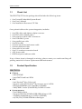
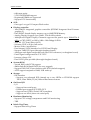
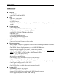
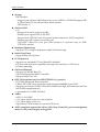
1
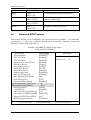
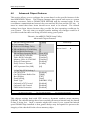
PEB-3730/3732 Series
Embedded System Board
User's Manual
P/N: B8981070
Version 1.0
Copyright © Portwell, Inc., 2004. All rights reserved.
All other brand names are registered trademarks of their respective owners.
Preface
Table of Contents
How to Use This Manual
Chapter 1 System Overview.......................................................................................................1-1
1.1 Check List ..................................................................................................................................... 1-3
1.2 Product Specification .................................................................................................................. 1-3
1.2.1 Mechanical Drawing......................................................................................................... 1-9
1.3 System Architecture .................................................................................................................... 1-9
Chapter 2 Hardware Configuration ...........................................................................................2-1
2.1 Jumper Setting ............................................................................................................................. 2-1
2.2 Connector Allocation .................................................................................................................. 2-4
Chapter 3 System Installation....................................................................................................3-1
3.1 INF Chipset Component Driver ................................................................................................ 3-1
3.2 Intel 855GM / 852GME Graphics Controller .......................................................................... 3-1
3.3 Intel Fast Ethernet Controller .................................................................................................... 3-2
3.4 Intel 82801DB AC’97 Codec Controller .................................................................................... 3-3
Chapter 4 BIOS Setup Information............................................................................................4-1
4.1 Entering Setup.............................................................................................................................. 4-1
4.2 Main Menu ................................................................................................................................... 4-2
4.3 Standard CMOS Setup Menu .................................................................................................... 4-3
4.4 IDE Adaptors Setup Menu......................................................................................................... 4-5
4.5 Advanced BIOS Features............................................................................................................ 4-6
4.6 Advanced Chipset Features ..................................................................................................... 4-10
4.7 Integrated Peripherals .............................................................................................................. 4-13
4.8 Power Management Setup ....................................................................................................... 4-19
4.9 PnP/PCI Configurations .......................................................................................................... 4-23
4.10 PC Health Status...................................................................................................................... 4-24
4.11 Frequency/Voltage Control................................................................................................... 4-25
4.12 Default Menu ........................................................................................................................... 4-26
4.13 Supervisor/User Password Setting ...................................................................................... 4-26
4.14 Exiting Selection ...................................................................................................................... 4-27
Chapter 5 Trouble shooting .......................................................................................................5-1
5.1 BIOS Setting.................................................................................................................................. 5-1
5.2 FAQ ............................................................................................................................................... 5-3
Appendix A System Memory Address Map
Appendix B Interrupt Request Lines (IRQ)
Preface
How to Use This Manual
The manual describes how to configure your PEB-3730/3732 series system to meet
various operating requirements. It is divided into five chapters, with each chapter
addressing a basic concept and operation of Single Board Computer.
Chapter 1 : System Overview. Presents what you have in the box and give you an
overview of the product specifications and basic system architecture for this series
model of single board computer.
Chapter 2 : Hardware Configuration. Shows the definitions and locations of
Jumpers and Connectors that you can easily configure your system.
Chapter 3 : System Installation. Describes how to properly mount the CPU, main
memory and Compact Flash to get a safe installation and provides a programming
guide of Watch Dog Timer function.
Chapter 4 : BIOS Setup Information. Specifies the meaning of each setup
parameters, how to get advanced BIOS performance and update new BIOS. In
addition, POST checkpoint list will give users some guidelines of trouble-shooting.
Chapter 5 : Troubleshooting. Provides various useful tips to quickly get PEB3730/3732 series running with success. As basic hardware installation has been
addressed in Chapter 3, this chapter will basically focus on system integration issues,
in terms of backplane setup, BIOS setting, and OS diagnostics.
The content of this manual and EC declaration document is subject to change
without prior notice. These changes will be incorporated in new editions of the
document. Portwell may make supplement or change in the products described in
this document at any time.
Updates to this manual, technical clarification, and answers to frequently asked
questions will be shown on the following web site : http://www.portwell.com/.
Preface
EC Declaration of Conformity
(To Be Added)
For the following equipment:
Product Name:
Model Name:
Trade Name:
is herewith confirmed to comply with the requirements set out in the Council
Directive on the Approximation of the Laws of the Member States relating to
Electromagnetic Compatibility Directive (89/336/EEC).
The equipment was
evaluated and passed the test, the following standards were applied :
EMC :
EN 55022
EN 50082-2
EN 61000-4-2
EN 61000-4-3
EN 61000-4-4
EN 61000-3-2
EN 61000-3-3
(1994/A1:1995 Class A)
(1991)
(1995)
(1996)
(1995)
(1995)
(1995)
The following manufacturer is responsible for this declaration :
Portwell, Inc.
(Company Name)
3F, No.88, Sec.1, Nei-Hu Rd., Taipei, Taiwan, R.O.C.
(Company Address)
Taipei, R.O.C.
Place
Date
Legal Signature of
Authorized Person
System Overview
Chapter 1
System Overview
PEB-3730VLA is designed based on Intel® 855GME with high performance and high
integration but low power consumption platform. It is positioned at innovation, high
integration and high quality Embedded System Board in the embedded computing
market.
The board is based on Intel 855GME chipset and latest high performance low power
processor, Intel® Pentium® M Processor, running at up to 1.6Ghz with 400Mhz
Process system bus and 90nm process technology with 533Mhz. With Intel 855GME
chipset that support high speed ECC DDR SDRAM, high-performance graphic
controller AGP 4X controller with dual display/Panel and Intel fast Ethernet
connection enable Portwell PEB-3730 series to provide most versatile low power
Embedded System Board (ESB) in the market.
All in all, PEB-3730 series are designed to meet all kinds of low power embedded
computing application. With Intel most advance mainstream chipset for low power
mobile computing 855GME, PEB-3730VLA is aiming the low power mobile
multimedia and networking applications in the market.
Its compact design with industry 5.25” ESB standard form factor makes it the most
favorable solution for high-density server. High reliability, compact size and easy-touse features fulfill the demand for critical embedded and Interactive client
application including Wearable computing, Heath care, Vehicle, POS, KIOSK, ATM,
Gaming and medical application.
Key Features:
Compact 5.25” ESB form factor to fit in most wide range of system architecture
Intel new generation mobile longevity chipset Intel® 855GME powered by
Pentium® M with frequencies of up to 2.0GHz (with uFC-PGA socket 478 for
easy processor configuration
Dual independent on-board display support CRT, LVDS and DVO for other
display possibility like DVI
On-board standard I/O, display, LVDS panel, network and audio to meet the
requirements of interactive client platform
On-board 10/100BASE-TX Ethernet to provide network connection
Up to 1GB high performance DIMM DDR SDRAM allows to run versatile
embedded programs but keep lower profile for slim system design for ultra
low voltage model
One PCI (with PCI expansion capability defined by EmbATX)
One Type II CF socket for 8~320MB Compact Flash disk to provide space of
resident system setting, data and software
PEB-3730/3732 Series User’s Manual
1-1
System Overview
PEB-3732 series
Portwell also provide a ultra low power model with Intel Celeron M 600Mhz
processor since this model adopt uFC-BGA2 packaged processor we only provide a
default model as PEB-3732VLA
PEB-3732VLA is based on Intel® 852GM with ultra low voltage Celeron M
processor. It is positioned at cost effective and low power fan-less Embedded System
Board in the growing embedded computing market.
The board is based on Intel 852GM chipset and latest Intel low power processor,
Intel® Celeron® M Processor, running at 600Mhz with 400Mhz Process system bus.
With Intel 852GM chipset that support high speed ECC DDR SDRAM, highperformance graphic controller AGP 4X controller with dual display/Panel and dual
Intel fast Ethernet connection enable Portwell PEB-3732 series to provide most
versatile low power Embedded System Board (ESB) in the market.
Key Features:
Compact 5.25” ESB form factor to fit in most wide range of system architecture
Intel new generation mobile longevity chipset Intel® 852GM powered by ULV
Celeron M 600 Mhz (with uFC-BGA, direct mount to board)
Dual independent on-board display support CRT, LVDS and DVO for other
display possibility
On-board standard I/O, display, LVDS panel, network and audio to meet the
requirements of interactive client platform
On-board 10/100BASE-TX Ethernet to provide network connection
Up to 1GB high performance DIMM DDR SDRAM allows to run versatile
embedded programs but keep lower profile for slim system design for ultra
low voltage model
One PCI (with PCI expansion capability defined by EmbATX)
One Type II CF socket for 8~320MB Compact Flash disk to provide space of
resident system setting, data and software
PEB-3730/3732 Series User’s Manual
1-2
System Overview
1.1
Check List
The PEB-3730/3732 series package should include the following items:
One Portwell Embedded System Board
One User’s Manual
One Installation Resources CD Title
One optional cable set for system integration, includes:
One IDE cable with 44pin to 40pin converter
One FDC cable (2.0mm pitch)
One serial port cable with 2 connectors
One USB cable, 2 ports
One parallel port cable
One VGA cable
One PS/2 keyboard and mouse cable
One Fast Ethernet Cable
One audio in/out cable
One I/O connector extension board
ATX power cable
HDD and power indicator cable
If any of these items is damaged or missing, please contact your vendor and keep all
packing materials for future replacement and maintenance.
1.2
Product Specification
PEB-3730VLA
Chipset
- Intel 855GME
- Intel GMCH and Intel ICH4
CPU
- Intel Pentium® M or Celeron M
- Support socket 478 Pentium® M processor up to 1.8GHz
- FSB speed 400MHz (easy upgrade to 533Mhz)
- 1MB/2MB L2 cache (Pentium-M), 2x32KB L1 cache
System memory
- One DIMM sockets
- Supports 200/266/333MHz DDR SDRAM up to 1GB
- Available bandwidth up to 2.1GB/s (DDR266)
- 64/128/256/512 Mb SDRAM technologies
PEB-3730/3732 Series User’s Manual
1-3
System Overview
- 64bit non-parity
- 2.5V DDR SDRAM support
- Registered DIMM not supported
- Support ECC functionality
SSD
- One type I or type II Compact Flash socket
Display controller
- Intel GMCH integrated graphics controller (855GME Integrated Intel Extreme
graphics 2)
- Intel DVMT shared display memory up to 64MB DDR Memory
- Analog Display Support up to 2048 x 1536 @ 60Hz refresh
- Multiplexed Digital Display Channels supports flat panels up to 2048x1536 @
60Hz or CRT/HDTV at 1920 x 1080 x 18 & 24bpp @ 85Hz
- AGP 4X. 1.5V (Intel Direct AGP)
- Software DVD at 30 fps, full screen
- Motion Video Acceleration
- Dual channel LVDS interface for LVDS Panel Display
- Support TMDS DVI port (through daughter board)
- Analogue and digital output through one DVI-I connector (on daughter board)
- Panel Signal voltage must be 3.3V or 5V
- Inverter voltage: 12V
- Dual LVDS ports possible (thorough daughter board)
System BIOS
- Award BIOS with PC’98 support
- 4Mbit flash ROM (Intel FWH) for easy upgrade
- Support DMI, PnP, Green function and ACPI (default support)
- ACPI support suspend to RAM, USB wake up
Storage
- IDE Interface
•Support one enhanced IDE channel up to two HDDs or CD-ROM support
PIO 4, Ultra DMA/33/66/100 and Bus master feature.
On Board I/O
- I/O
•Support four serial ports
•Parallel port support SPP/EPP/ECP
•Support four USB 2.0 Ports;UHCI compliant
•Support one IrDA (share one serial port)
Hardware Monitoring
- Support CPU voltage, temperature and FAN monitoring
- TBD
Watch Dog Timer
- Support Watch-Dog Timer
PEB-3730/3732 Series User’s Manual
1-4
System Overview
PCI Expansion
- Support one standard PCI slot (EmbATX defined)
- PCI slot with expansion capability (through riser card up to 3 PCI slots)
- PCI bus mastering
On Board Ethernet
- Support 10/100 MB Base-TX
- One ICH4 Integrated MAC controller with external 10/100 Mb phy 562 )
- Support two LEDs to indicator LAN access and link status on RJ45 jack
Audio
- AC97 v2.3 CODEC
- 1/8” photo jack for line in or microphone
- 1/8” photo jack for line out
- 4-pin stereo CDIN header for external CD line in
ACPI compliant support the full-on (S0), Stop Grant (S1), power management
states if ATX power supply unit applied
Real Time Clock/Calendar (RTC)
- Compatible for 7 years of data retention to support real Y2K
- An external Li battery
- Overcurrent protection to comply with IEC 601
Power on/off
- Soft on and 4 seconds override
- Header for connection to membrane switch
Keyboard and PS/2 Mouse interface
- Support one mini-DIN 6-pin connectors for keyboard and mouse
Internal Connector
- IDE connector
- LCD LVDS interfaces
- LCD inverter interface
- PS/2 mouse connector
- 3-pin, 0.10” pitch fan header
- 8-pin input power header
- 8-pin header for connection to membrane switch panel
- 2-pin reset header
- 10-pin header x2 for USB
Physical and Environmental requirements
- Outline Dimension (L x W): 203mm X 146mm (with Portwell standard 5.25” ESB
dimension and mounting)
- Power requirements: TBD
- Operating temperature: 0 to 55 °C
- Relative Humidity 5% to 95%, non-condensing
PEB-3730/3732 Series User’s Manual
1-5
System Overview
PEB-3732VLA
Chipset
- Intel 852GM
- Intel GMCH and Intel ICH4
CPU
- Intel ULV Celeron M
- FSB speed 400MHz
- 2x32KB L1 cache
- 512KB L2 cache (Celeron-M) (also support 0K L2 cache model by specific project
based)
System memory
- One DIMM sockets
- Supports 200/266MHz DDR SDRAM up to 1GB
- Available bandwidth up to 2.1GB/s (DDR266)
- 64/128/256/512 Mb SDRAM technologies
- 64bit non-parity
- 2.5V DDR SDRAM support
- Registered DIMM not supported
- Support ECC functionality
SSD
- One type I or type II Compact Flash socket
Display controller
- Intel GMCH integrated graphics controller (852GM Integrated Intel Extreme
graphics 2)
- Intel DVMT shared display memory up to 64MB DDR Memory
- Analog Display Support up to 2048 x 1536 @ 60Hz refresh
- Multiplexed Digital Display Channels supports flat panels up to 2048x1536 @
60Hz or CRT/HDTV at 1920 x 1080 x 18 & 24bpp @ 85Hz
- AGP 4X. 1.5V (Intel Direct AGP)
- Software DVD at 30 fps, full screen
- Motion Video Acceleration
- Dual channel LVDS interface for LVDS Panel Display
- Support TMDS DVI port (through daughter board)
- Analogue and digital output through one DVI-I connector (on daughter board)
- Panel Signal voltage must be 3.3V or 5V
- Inverter voltage: 12V
- Dual LVDS ports possible (thorough daughter board)
System BIOS
- Award BIOS with PC’98 support
- 4Mbit flash ROM (Intel FWH) for easy upgrade
- Support DMI, PnP, Green function and ACPI (default support)
- ACPI support suspend to RAM, USB wake up
PEB-3730/3732 Series User’s Manual
1-6
System Overview
Storage
- IDE Interface
•Support one enhanced IDE channel up to two HDDs or CD-ROM support PIO
4, Ultra DMA/33/66/100 and Bus master feature.
•IDE header x1
On Board I/O
- I/O
•Support four serial ports for UART
•Parallel port support SPP/EPP/ECP
•Support four USB 2.0 Ports; four panel mount connectors; UHCI compliant
•Support one IrDA (share one serial port)
•One IEEE 1394A fire wire port (This function is optional only for PEB3732VL2A model)
Hardware Monitoring
- Support CPU voltage, temperature and FAN monitoring
Watch Dog Timer
- Support Watch-Dog Timer
PCI Expansion
- Support one standard PCI slot (EmbATX defined)
- PCI slot with expansion capability (through riser card up to 3 PCI slots)
- PCI bus mastering
On Board Ethernet
- Support 10/100 MB Base-TX
- One ICH4 Integrated MAC controller
- Support Wake-on-LAN
IEEE 1394 (optional only for PEB-3732VL2A, by project)
- PCI 1394a integrated Host controller
- 1394a OHCI Link Layer controller with integrated 400Mbit 2 port PHY
- Supports provisions of IEEE 1394-1995 standard for high performance serial bus
and P1394a supplement 4.0
- 6-pin header for 2 IEEE 1394 Port
Audio
- AC97 v2.3 CODEC
- 1/8” photo jack for line in or microphone
- 1/8” photo jack for line out
- 4-pin stereo CDIN header for external CD line in
ACPI compliant support the full-on (S0), Stop Grant (S1), power management
states if ATX power supply unit applied
PEB-3730/3732 Series User’s Manual
1-7
System Overview
Real Time Clock/Calendar (RTC)
- Compatible for 7 years of data retention to support real Y2K
- An external Li battery
- Overcurrent protection to comply with IEC 601
Power on/off
- Soft on and 4 seconds override
- Header for connection to membrane switch
Keyboard and PS/2 Mouse interface
- Support one mini-DIN 6-pin connectors for keyboard and mouse
Internal Connector
- IDE connector
- LCD LVDS interfaces
- LCD inverter interface
- PS/2 mouse connector
- 3-pin, 0.10” pitch fan header
- 8-pin input power header
- 8-pin header for connection to membrane switch panel
- 2-pin reset header
- 10-pin header x2 for USB
- 6-pin header for 2 IEEE 1394 Port (optional)
Physical and Environmental requirements
- Outline Dimension (L x W): 203mm X 146mm
- Power requirements: TBD
- Operating temperature: 0 to 55 °C
- Relative Humidity 5% to 95%, non-condensing
PEB-3730/3732 Series User’s Manual
1-8
System Overview
1.2.1
Mechanical Drawing
1.3
System Architecture
The system architecture of PEB-3730/3732 includes two main Intel EID chips, Intel
855GME/852GM chipset supports Intel low power Pentium M or Celeron M
processor, DDR-SDRAM, Intel extreme graphics 2 and its ICH4 supports PCI bus
interface, APM, ACPI compliant power management, USB port, SMBus
communication, and Ultra DMA/33/66/100 IDE Master, and it also provides a Fast
Ethernet controller. The Winbond I/O Controller is responsible for PS/2
Keyboard/Mouse, UARTs, FDC, Hardware Monitor, Parallel, Watch Dog Timer and
Infrared interface.
The special pin configuration of the CPU socket adopts the uFC-PGA2 478 pins in
total. This new generation Pentium M or Celeron M provides better performance to
many applications.
As for PEB-3732 the Ultra Low Voltage Celeron M is in uFC-BGA 2 is populated on
board at 600Mhz with FSB 400Mhz.
PEB-3730/3732 Series User’s Manual
1-9
System Overview
The on-board PCI connector can supports additional embATX PCI riser card for
further PCI extension up to 3 PCI devices.
PEB-3730 series System Block Diagram
PEB-3730/3732 Series User’s Manual
1-10
System Overview
PEB-3732 series System Block Diagram
PEB-3730/3732 Series User’s Manual
1-11
Hardware Configuration
Chapter 2
Hardware Configuration
This chapter gives the definitions and shows the positions of jumpers, headers and
connector. All of the configuration jumpers on PEB-3730/3732 series are in proper
position. The default jumper settings shipped from factory are marked with an
astral (Ì).
2.1
Jumper Setting
Jumpers provide a convenient and reversible way of reconfiguring the circuitry on a
printed circuit board. When reconfiguring the system, you may need to change
jumper settings on the system board. In the following sections, Short means
covering a jumper cap over jumper pins; Open or NC (Not Connected) means
removing a jumper cap from jumper pins. Refer to Figure 2-1 for the Jumper
locations.
PEB-3730/3732 Series User’s Manual
2-1
Hardware Configuration
Figure 2-1
PEB-3730/3732 Series Jumper Location
JP1: LVDS Panel Power Source Selector
JP1
1-2
2-3
LVDS Panel VDD
3.3V Ì
5V
JP3: Power Source for CPU VCCA Selector
JP3
1-2
2-3
CPU VCCA
1.8V for BANIAS Ì
1.5V for DOTHAN
JP4: Power Source for CPU VCCP Selector
JP4
1-2
2-3
LVDS VCCP
1.2V for BANIAS Ì
1.35V for DOTHAN
PEB-3730/3732 Series User’s Manual
2-2
Hardware Configuration
JP5: RTC CMOS Clear Jumper Setting
JP5
OFF
1-2
Function
Normal Operation Ì
Clear CMOS Contents
JP6: LVDS Panel Resolution Selector
JP6
OFF
1-2
3-4
1-2, 3-4
5-6
1-2,5-6
Resolution
Disable LVDS Panel
800*600,18Bits
1024*768,18Bits
1024*768,24Bits Ì
1280*1024,18Bits
1280*1024,24Bits
JP7: LVDS Panel Backlight Active Type Selector
JP7
1-2
2-3
Backlight Power Active Type
Low Active
High Active Ì
JP8: LVDS Panel Backlight Power Type Selector
JP8
1-2
2-3
Backlight Power Type
5V
12V Ì
JP9: COM2 RS-232/RS-422/485 Selector
Function
RS-232
RS-422
RS-485
Jump Setting
5-6,9-11,10-12,15-17,16-18
3-4,7-9,8-10,13-15,14-16,21-22
1-2,7-9,8-10,19-20 Ì
PEB-3730/3732 Series User’s Manual
2-3
Hardware Configuration
2.2
Connector Allocation
I/O peripheral devices and flash disk are connected to the interface connectors and
CF socket on this board computer (Figure 2-2).
Figure 2-2
PEB-3730/3732 Series Connector Location
Connector Function List
Connector
Function
CN1
ATX Power Connector
CN2
1394 Connector
J1
J2
J6
J8
J9
J10
Remark
PEB-3730VLA & PEB3732VLA NONE
COM Port1/COM Port2/COM Port3/COM
Port4 Connector
FDC Interface Connector
Power ON/OFF ;IDE1/Campact Flash Active
LED; System Reset Header
USB Port1/USB Port2 Interface Connector
USB Port3/USB Port4 Interface Connector
Front Panel SMBUS Header
PEB-3730/3732 Series User’s Manual
2-4
Hardware Configuration
J11
J12
J13
J14
J15
J16
J18
J19
CD IN Connector
System FAN Connector
IR Connector
LVDS Interface Connector
CPU FAN Connector
MIC/Line IN/Line OUT Interface Connector
BUZZER Connector
LAN2 Connector
J20
J21
J24
J27
J29
JP30
JP31
JP33
J34
J35
Thermal Sense Interface Connector (Optional)
IDE1 Interface Connector
Front Panel Connector
LVDS Inverter Connector
LAN1 Connector
GPIO Interface Connector
PS/2 Keyboard/Mouse Connector
Compact Flash Connector
DVI Interface Connector
VGA Connector
PEB-3730VLA & PEB3732VLA NONE
Pin Assignments of Connectors
CN1: ATX Power Connector
PIN No.
1
2
3
4
5
6
7
8
Signal Description
+5V
+5V
+5VSB
+12V
PS-ON
GND
GND
ATX PWROK
CN2: 1394 Connector (PS. PEB-3730VLA & PEB-3732VLA NONE)
PIN No.
1
2
3
4
5
6
Signal Description
+12V
GND
Port BPort B+
Port APort A+
PEB-3730/3732 Series User’s Manual
2-5
Hardware Configuration
J1: COM Port1/COM Port2/COM Port3/COM Port4 Connector
PIN No.
1
3
5
7
9
11
13
15
17
19
21
23
25
27
29
31
33
35
37
39
Signal Description
COM1 DCD
COM1 RXD
COM1 TXD
COM1 DTR
COM1 GND
COM2 DCD/RS-485 TXCOM2 RXD/RS-485 TX+
COM2 TXD/RS-422 RX+
COM2 DTR/RS-422 RXCOM2 GND
COM3 DCD
COM3 RXD
COM3 TXD
COM3 DTR
COM3 GND
COM4 DCD
COM4 RXD
COM4 TXD
COM4 DTR
COM4 GND
PIN No.
2
4
6
8
10
12
14
16
18
20
22
24
26
28
30
32
34
36
38
40
Signal Description
COM1 DSR
COM1 RTS
COM1 CTS
COM1 RI
NC
COM2 DSR
COM2 RTS
COM2 CTS
COM2 RI
NC
COM3 DSR
COM3 RTS
COM3 CTS
COM3 RI
NC
COM4 DSR
COM4 RTS
COM4 CTS
COM4 RI
NC
PIN No.
2
4
6
8
10
12
14
16
18
20
22
24
26
28
30
32
34
Signal Description
Drive Density Select bit 0
NC
Drive Density Select bit 1
INDEX
Motor A On
Drive Select B
Drive Select A
Motor B On
DIR
STEP
Write data
Write enable
Track 0
Write protected
RDATA
Head Select
Diskette Change
J2: FDC Interface Connector
PIN No.
1
3
5
7
9
11
13
15
17
19
21
23
25
27
29
31
33
Signal Description
GND
GND
GND
GND
GND
GND
GND
GND
GND
GND
GND
GND
GND
GND
GND
GND
GND
PEB-3730/3732 Series User’s Manual
2-6
Hardware Configuration
J6: Power ON/OFF ;IDE1/Campact Flash Active LED; System Reset Header
PIN No.
1
2
3
4
5
6
Status
ON: Power ON/OFF
OFF: Normal
LED Power+
LED PowerON: Reset
OFF: Normal
J8: USB Port1/USB Port2 Interface Connector
PIN No.
1
3
5
7
9
Signal Description
USB1 Power
USB1 DataUSB1 Data+
USB1 GND
GND
PIN No.
2
4
6
8
10
Signal Description
GND
USB2 GND
USB2 Data+
USB2 DataUSB2 Power
J9: USB Port3/USB Port4 Interface Connector
PIN No.
1
3
5
7
9
Signal Description
USB3 Power
USB3 DataUSB3 Data+
USB3 GND
GND
PIN No.
2
4
6
8
10
Signal Description
GND
USB4 GND
USB4 Data+
USB4 DataUSB4 Power
J10: Front Panel SMBUS Header
PIN No.
1
3
4
5
Signal Description
SMBUS Clock
GND
SMBUS Data
+5V
J11: CD IN Connector
PIN No.
1
2
3
4
Signal Description
CD IN Left
CD IN GND
CD IN GND
CD IN Right
PEB-3730/3732 Series User’s Manual
2-7
Hardware Configuration
J12: System FAN Connector
PIN No.
1
2
3
Function
GND
12V
Sense
J13: IR Connector
PIN No.
1
2
3
4
5
6
Signal Description
5V
NC
Receiving Input
GND
Transmitter Output
NC
J14: LVDS Interface Connector
PIN No.
2
4
6
8
10
12
14
16
18
20
22
24
26
28
30
Signal Description
LVDS VDD
Channel A Data1Channel A Data1Channel A Data2Channel A Data3Channel A ClockPanel DDC Clock
GND
Channel B Data1Channel B Data1Channel B Data2Channel B Data3Channel B ClockPanel DDC Clock
GND
PIN No.
1
3
5
7
9
11
13
15
17
19
21
23
25
27
29
Signal Description
LVDS VDD
Channel A Data0+
Channel A Data1+
Channel A Data2+
Channel A Data3+
Channel A Clock+
Panel DDC Data
GND
Channel B Data0+
Channel B Data1+
Channel B Data2+
Channel B Data3+
Channel B Clock+
Panel DDC Data
GND
J15: CPU FAN Connector
PIN No.
1
2
3
Function
GND
12V
Sense
PEB-3730/3732 Series User’s Manual
2-8
Hardware Configuration
J16: MIC/Line IN/Line OUT Interface Connector
PIN No.
1
3
5
7
9
Signal Description
MIC
Line IN Left
Line IN Right
Line OUT Left
Line OUT Right
PIN No.
2
4
6
8
Signal Description
GND
GND
GND
GND
J18: BUZZER Connector
PIN No.
1
2
Signal
BUZZER+
BUZZER -
J19: LAN2 Connector (PS. PEB-3730VLA & PEB-3732VLA NONE)
PIN No.
1
3
5
7
9
11
13
15
Signal Description (MDI)
LAN2 BI_DALAN2 BI_DBLAN2 BI_DCLAN2 BI_DDLAN2 LINK100LAN2 LINK1000Active LEDLink LED-
PIN No.
2
4
6
8
10
12
13
14
Signal Description (MDI)
LAN2 BI_DA+
LAN2 BI_DB+
LAN2 BI_DC+
LAN2 BI_DD+
3.3V
GND
LAN2 GND
LAN2 GND
J20: Thermal Sense Interface Connector (Optional)
PIN No.
1
2
Signal
Thermal Sensor Resistor
Thermal Sensor Resistor
PEB-3730/3732 Series User’s Manual
2-9
Hardware Configuration
J21: IDE1 Interface Connector
PIN No.
1
3
5
7
9
11
13
15
17
19
21
23
25
27
29
31
33
35
37
39
41
43
Signal Description
RESET#
D7
D6
D5
D4
D3
D2
D1
D0
GND
DREQA
IOW#
IOR#
IOCHRDY
DACKA
IRQ14
SA1
SA0
HDC CS0#
HD_LED
5V
GND
PIN No.
2
4
6
8
10
12
14
16
18
20
22
24
26
28
30
32
34
36
38
40
42
44
Signal Description
GND
D8
D9
D10
D11
D12
D13
D14
D15
N/C
GND
GND
GND
GND
GND
N/C
N/C
SA2
HDC CS1#
GND
5V
GND
J24: Front Panel Connector
PIN No.
1
2
3
4
5
Signal Description
5V
Power LED
Key lockGND
J27: LVDS Inverter Connector
PIN No.
1
2
3
4
5
6
7
Signal Description
12V
GND
GND
5V
SMBCLK
LVDS Backlight
LVDS Enable
PEB-3730/3732 Series User’s Manual
2-10
Hardware Configuration
J29: LAN1 Connector
PIN No.
1
3
5
7
9
11
13
15
Signal Description (MDI)
LAN1 BI_DALAN1 BI_DBLAN1 BI_DCLAN1 BI_DDLAN1 LINK100LAN1 LINK1000Active LEDLink LED-
PIN No.
2
4
6
8
10
12
13
14
Signal Description (MDI)
LAN1 BI_DA+
LAN1 BI_DB+
LAN1 BI_DC+
LAN1 BI_DD+
3.3V
GND
LAN1 GND
LAN1 GND
PIN No.
2
4
6
8
10
Signal Description
GPO 0
GPO 1
GPO 2
GPO 3
5V
PIN No.
2
4
6
8
10
Signal Description
Keyboard Data
NC
GND
5V
Keyboard Clock
PIN No.
2
4
6
8
10
12
14
16
18
20
Signal Description
JP30: GPIO Interface Connector
PIN No.
1
3
5
7
9
Signal Description
GPI 4
GPI 5
GPI 6
GPI 7
GND
JP31: PS/2 Keyboard/Mouse Connector
PIN No.
1
3
5
7
9
Signal Description
Mouse Data
NC
GND
5V
Mouse Clock
J33: Compact Flash Connector
PIN No.
25
24
23
7
9
11
13
15
17
19
Signal Description
GND
D4
D6
#CS0
#ATA SEL
A8
VCC
A5
A3
A1
PEB-3730/3732 Series User’s Manual
D3
D5
D7
A10
A9
A7
A6
A4
A2
A0
2-11
Hardware Configuration
21
23
25
27
29
31
33
35
37
39
41
43
45
47
49
D0
D2
#CD2
D11
D13
D15
#VS1
#IOWR
INTRQ
#CSEL
#RESET
#INPACK
#DASP
D8
D10
22
24
26
28
30
32
34
36
38
40
42
44
46
48
50
D1
#IOCS16
#CD1
D12
D14
#CS1
#IORD
#WE
VCC
#VS2
IORDY
#REG
#PDIAG
D9
GND
J34: DVI Interface Connector
PIN No.
1
3
5
7
9
11
13
15
17
19
21
23
25
27
29
31
33
35
37
39
41
43
Signal Description
NC
NC
NC
NC
NC
DVOC D11
DVOC D10
DVOC D9
DVOC D8
DVOC D7
DVOC D6
DVOC D5
DVOC D4
DVOC D3
DVOC D2
DVOC D1
DVOC D0
5V
5V
5V
GND
DVOC Clock+
PEB-3730/3732 Series User’s Manual
PIN No.
2
4
6
8
10
12
14
16
18
20
22
24
26
28
30
32
34
36
38
40
42
44
Signal Description
NC
NC
NC
NC
NC
DVO Detect
DVOBC INTR
DVOC Blank
NC
Reset
NC
I2C Data
I2C Clock
3.3V
3.3V
1.5V
GND
DVOC HSYNC
GND
DVOC VSYNC
GND
DVOC Clock-
2-12
Hardware Configuration
J35: VGA Connector
PIN No.
1
3
5
7
9
Signal Description
R
G
B
HSYNC
VSYNC
PEB-3730/3732 Series User’s Manual
PIN No.
2
4
6
8
10
Signal Description
VCC
GND
NC
DATA
CLK
2-13
System Installation
Chapter 3
System Installation
This chapter provides the instructions to set up PEB-3730/3732 series. The additional
information enclosed to help you set up onboard PCI device and handle Watch Dog
Timer (WDT) operation in software programming.
3.1
INF Chipset Component Driver
Intel 855GM / 852GME chipset is a new chipset that a few old operating systems
might not be able to recognize. To overcome this compatibility issue, for Windows
Operating Systems such as Windows-95/98/98SE/2000, please install INF Chipset
Component driver before any of other Drivers are installed.
You can find very easily the INF chipset component driver in \Chipset\Intel\INF
directory of PEB-3730/3732 series CD-title. Please execute “infinst_autol.exe” to start
installation.
3.2
Intel 855GM / 852GME Graphics Controller
Intel 855GM / 852GME chipset is the result of new design approach to optimize the
shared memory architecture while maintaining the cost benefits of integration
through Direct AGP and Dynamic Video Memory Technology.
With no additional video adaptor, this onboard video will be the system display
output. However, system will automatically switch to off-board video adaptor if
there is any. In this case, onboard 855GM / 852GME graphic features will be
disabled.
There is no way to disable this onboard video function, unless one off-board PCI
video card is applied onto the backplane. In this case, the off-board video card shall
be picked up first based on the default BIOS setup (Initial Display First) in
“Integrated Peripheral” Setup Menu.
Drivers Support
Please find Intel 855GM / 852GME driver in /Graphics directory of PEB-3730/3732
series CD-title. Drivers support Windows-95/98/98SE/ME, Windows-NT 4.0,
Windows-2000, OS2, and Linux.
(1) Windows-95/98/98SE/ME: Please execute \Graphic\Intel\Extreme\win9x\
win9x1361.exe to start graphics driver installation.
PEB-3730/3732 Series User’s Manual
3-1
System Installation
(2) Windows-NT 4.0: Please execute \Graphic\Intel\Extreme\WinNT4\
winnt41361.exe to start graphics driver installation.
(3) Windows-2000/XP: Please execute \Graphic\Intel\Extreme\Win2KXP\
win2k_xp141.exe to start graphics driver installation.
(4) Redhat Linux V6.2: Please refer to the “20030425-i386.txt” file in
\Graphic\Intel\Extreme\Linux directory for graphics drivers installation guide.
3.3
Intel Fast Ethernet Controller
This Fast Ethernet function is supported by Intel 82562/82551/82540 embedded
PHY and interfaced via Intel 82562EX Platform LAN Connect (PLC).
Drivers Support
Please find LAN driver in \Ethernet\ IntelPRO\ directory of PEB-3730/3732 series
CD-title. The drivers support Windows-NT 3.51/4.0, Windows-95/98/98SE/ME,
Windows-2000, and SCO OpenServer 5.0.2, SCO Unixware 7.0, OS2 and Linux.
On-board LED Indicator (for LAN status)
PEB-3730/3732 series provides two LED indicators with RJ-45 connector to report
Intel 82801BA MAC Fast Ethernet interfaces status. Please refer to the table below as
a quick reference guide.
Intel 82562EX
Name of LED
MAC
Amber
LAN speed LED
Green
LAN active LED
Green
LAN Link Integrity LED
Operation of Ethernet Port
ON
OFF
100 Mbps
10 Mbps
Active
No active
Good link in 10 or No link
100 Mbps
There is no way to disable this onboard Ethernet function.
PEB-3730/3732 Series User’s Manual
3-2
System Installation
3.4
Intel 82801DB AC’97 Codec Controller
This on-board Audio function is supported by Intel 82801DB (ICH4) embedded
AC’97 Codec Controller.
Drivers Support
Please find Sound driver in \Audio\AC97\Realtek directory of PEB-3730/3732
series CD-title. The drivers support Windows-NT 4.0, Windows-95/98/98SE,
Windows-2000 and Windows-XP.
To disable this onboard Audio function, please configure the “Integrated Peripheral”
Setup Menu in BIOS. Change the “AC’97 Audio” setting to “Disabled” will help you
to turn off this PCI Audio device.
PEB-3730/3732 Series User’s Manual
3-3
BIOS Setup Information
Chapter 4
BIOS Setup Information
PEB-3730/3732 series is equipped with the AWARD BIOS stored in Flash ROM. The
BIOS has a built-in Setup program that allows users to modify the basic system
configuration easily. This type of information is stored in CMOS RAM so that it
retained during power-off periods. When system is turned on, PEB-3730/3732 series
communicates with peripheral devices and check its hardware resources against the
configuration information stored in the CMOS memory. If any error detected, or the
CMOS parameters need to be initially defined, the diagnostic program will prompt
the user to enter the SETUP program. Some errors are significant enough to abort the
start-up.
4.1
Entering Setup
Turn on or reboot the computer. When the message “Hit <DEL> if you want to run
SETUP” appears, press <Del> key immediately to enter BIOS setup program.
If the message disappears before you respond, but you still wish to enter Setup,
please restart the system to try “COLD START” again by turning it OFF and then
ON, or touch the "RESET" button. You may also restart from “WARM START” by
pressing <Ctrl>, <Alt>, and <Delete> keys simultaneously. If you do not press
the keys at the right time and the system will not boot, an error message will be
displayed and you will again be asked to,
Press <F1> to Run SETUP or Resume
In HIFLEX BIOS setup, you can use the keyboard to choose among options or
modify the system parameters to match the options with your system. The table
below will show you all of keystroke functions in BIOS setup.
↑↓→ ←
Enter
+ / - /PU /PD
ESC
F1
F2
F5
F6
F7
F9
F10
General Help
: Move
: Select
: Value
: Exit
: General Help
: Item Help
: Previous Values
: Fail-Safe Defaults
: Optimized Defaults
: Menu in BIOS
: Save
PEB-3730/3732 Series User’s Manual
4-1
BIOS Setup Information
4.2
Main Menu
Once you enter PEB-3730/3732 series AWARD BIOS CMOS Setup Utility, you
should start with the Main Menu. The Main Menu allows you to select from eleven
setup functions and two exit choices. Use arrow keys to switch among items and
press <Enter> key to accept or bring up the sub-menu.
Phoenix- AwardBIOS CMOS Setup Utility
f Standard CMOS Features
f Advanced BIOS Features
f Advanced Chipset Features
f Integrated Peripherals
f Power Management Setup
f PnP/PCI Configurations
f PC Health Status
f Frequency/Voltage Control
Load Fail-Safe Defaults
Load Optimized Defaults
Set Supervisor Password
Set User Password
Save & Exit Setup
Exit Without Saving
ESC : Quit
F10 : Save & Exit Setup
↑ ↓ → ← : Select Item
Time, Date, Hard Disk Type …
Note:
It is strongly recommended to reload Optimal Setting if CMOS is lost or BIOS is
updated.
PEB-3730/3732 Series User’s Manual
4-2
BIOS Setup Information
4.3
Standard CMOS Setup Menu
This setup page includes all the items in a standard compatible BIOS. Use the arrow
keys to highlight the item and then use the <PgUp>/<PgDn> or <+>/<-> keys to
select the value or number you want in each item and press <Enter> key to certify it.
Follow command keys in CMOS Setup table to change Date, Time, Drive type, and
Boot Sector Virus Protection Status.
Phoenix- AwardBIOS CMOS Setup Utility
Standard CMOS Features
Date (mm:dd:yy)
Time (hh:mm:ss)
f IDE Primary Master
f IDE Primary Slave
f IDE Secondary Master
f IDE Secondary Slave
Tue, May 18 2004
10 : 29 : 50
[Maxtor 52049H3]
[None]
[None]
[None]
Drive A
Drive B
[1.44M, 3.5 in.]
[None]
Video
Halt On
[EVG/VGA]
[All, But Keyboard]
Base Memory
Extended Memory
Total Memory
640K
1014784K
1015808K
↑↓→←: Move
Enter: Select
F5: Previous Values
PEB-3730/3732 Series User’s Manual
Item Help
Menu Level
f
Change the day, month,
year and century
+/-/PU/PD: Value
F10: Save
ESC: Exit
F1: General Help
F6: Fail-Safe Defaults
F7: Optimized Defaults
4-3
BIOS Setup Information
Menu Selections
Item
Options
Date
mm:dd:yy
Time
hh:mm:ss
IDE Primary
Options are in its sub
Master
menu
IDE Primary
Options are in its sub
Slave
menu
IDE Secondary Options are in its sub
Master
menu
IDE Secondary Options are in its sub
Slave
menu
Drive A
None
Drive B
360K, 5.25 in
1.2M, 5.25 in
720K, 3.5 in
1.44M, 3.5 in
2.88M, 3.5 in
Video
EGA/VGA
CGA 40
CGA 80
MONO
Halt On
All Errors
No Errors
All, But Keyboard
All, But Diskette
All, But Disk/Key
Base Memory
640K
Extended
Memory
Total Memory
N/A
N/A
PEB-3730/3732 Series User’s Manual
Description
Change the day, month, year and century
Change the internal clock
Press <Enter> to enter the sub menu of
detailed options
Press <Enter> to enter the next page for
detail hard drive settings
Press <Enter> to enter the next page for
detail hard drive settings
Press <Enter> to enter the next page for
detail hard drive settings
Press <Enter> to enter the next page for
detail hard drive settings
Select the default video device
Select the situation in which you want the
BIOS to stop the POST process and notify
you
Displays the amount of conventional
memory detected during boot up
Displays the amount of extended memory
detected during boot up
Displays the total memory available in the
system
4-4
BIOS Setup Information
4.4
IDE Adaptors Setup Menu
The IDE adapters control the IDE devices, such as hard disk drive or CDROM drive.
It uses a separate sub menu to configure each hard disk drive.
Phoenix- AwardBIOS CMOS Setup Utility
IDE Primary Master
IDE HDD Auto-Detection
Press Enter
IDE Primary Master
Access Mode
Auto
Auto
Capacity
20492MB
Cylinder
Head
Precomp
Landing Zone
Sector
39704
16
0
39703
63
↑↓→←: Move
Enter: Select
F5: Previous Values
None
Auto
Manual
Access Mode
Menu Level
f
To atuo-detect the HDD’s
size, head … on this
channel
+/-/PU/PD: Value
F10: Save
ESC: Exit
F1: General Help
F6: Fail-Safe Defaults
F7: Optimized Defaults
Menu Selections
Item
Options
IDE HDD Auto- Press Enter
detection
IDE Primary
Master
Item Help
Description
Press Enter to auto-detect the HDD on this
channel. If detection is successful, it fills
the remaining fields on this menu.
Selecting ‘manual’ lets you set the
remaining fields on this screen. Selects the
type of fixed disk. "User Type" will let you
select the number of cylinders, heads, etc.
Note: PRECOMP=65535 means NONE !
Choose the access mode for this hard disk
CHS
LBA
Large
Auto
Capacity
Auto Display your Disk drive capacity (Approximated).
disk drive size
Note that this size is usually slightly
greater than the size of a formatted disk
given by a disk checking program.
The following options are selectable only if the ‘IDE Primary Master’ item is set to
‘Manual’
Cylinder
Min = 0
Set the number of cylinders for this hard
PEB-3730/3732 Series User’s Manual
4-5
BIOS Setup Information
Head
Precomp
Landing zone
Sector
4.5
Max = 65535
Min = 0
Max = 255
Min = 0
Max = 65535
Min = 0
Max = 65535
Min = 0
Max = 255
disk
Set the number of read/write heads
**** Warning: Setting a value of 65535
means no hard disk
****
Number of sectors per track
Advanced BIOS Features
This section allows you to configure your system for basic operation. You have the
opportunity to select the system’s default speed, boot-up sequence, keyboard
operation, shadowing and security.
Phoenix- AwardBIOS CMOS Setup Utility
Advanced BIOS Features
CPU Feature
Virus Warning
CPU L1 Cache
CPU L2 Cache
Quick Power On Self Test
First Boot Device
Second Boot Device
Third Boot Device
Boot Other Device
Swap Floppy Seek
Boot Up Floopy Seek
Boot up NumLock Status
Gate A20 Option
Typematic Rate Setting
X Typematic Rate (Chars/sec)
X Typematic delay (Msec)
Security Option
APIC Mode
MPS Version Control For OS
OS Select For DRAM > 64MB
Report No FDD For WIN 95
Small Logo(EPA) Show
↑↓→←: Move
Enter: Select
F5: Previous Values
PEB-3730/3732 Series User’s Manual
[Press Enter]
[Disabled]
[Enabled]
[Enabled]
[Enabled]
[Floppy]
[HDD-0]
[LS120]
[Enabled]
[Disabled]
[Enabled]
[On]
[Fast]
[Disabled]
6
250
[Setup]
[Enabled]
[1.4]
[Non-OS2]
[No]
[Disabled]
Item Help
Menu Level
f
+/-/PU/PD: Value
F10: Save
ESC: Exit
F1: General Help
F6: Fail-Safe Defaults
F7: Optimized Defaults
4-6
BIOS Setup Information
Virus Warning
It allows you to choose the VIRUS warning feature for IDE Hard Disk boot sector
protection. If this function is enabled and someone attempt to write data into this
area, BIOS will show a warning message on screen and alarm beep.
Enabled
Disabled
Activates automatically when the system boots up causing a
warning message to appear when anything attempts to access the
boot sector or hard disk partition table.
No warning message will appear when anything attempts to access
the boot sector or hard disk partition table.
CPU L1 Cache / CPU L2 Cache
These two categories speed up memory access.
CPU/chipset design.
Enabled
Disabled
However, it depends on
Enable cache
Disable cache
Quick Power On Self Test
Allows the system to skip certain tests while booting. This will decrease the time
needed to boot the system.
Enabled
Disabled
Enable quick POST
Normal POST
First/Second/Third Boot Device
Select your Boot Device Priority.
The choice: Floppy, LS120, HDD-0, SCSI, CDROM, HDD-1, HDD-2 HDD-3, ZIP100,
USB-FDD, USB-ZIP, USB-CDROM, USB-HDD and Disabled.
Boot Other Device
Select Your Boot Device Priority.
The choice: Enabled, Disabled.
Swap Floppy Drive
If the system has two floppy drives, choose enable to assign physical driver B to
logical drive A and Vice-Versa.
The choice: Enabled, Disabled.
PEB-3730/3732 Series User’s Manual
4-7
BIOS Setup Information
Boot Up Floppy Seek
Enabled tests floppy drives to determine whether they have 40 or 80 tracks.
The choice: Enabled, Disabled.
Boot Up NumLock Status
Select power on state for NumLock.
The choice: Off, On.
Gate A20 Option
Fast-lets chipsets control Gate A20 and Normal – a pin in the keyboard controller
controls Gate A20. Default is Fast.
The choice: Normal, Fast.
Typematic Rate Setting
Keystrokes repeat at a rate determined by the keyboard controller – When enabled,
the typematic rate and typematic delay can be select.
The choice: Enabled, Disabled.
Typematic Rate (Chars/sec)
The rate at which character repeats when you hold down a key.
The choice: 6, 8, 10, 12, 15, 20, 24, 30.
Typematic delay (Msec)
The delay before key strokes begin to repeat.
The choice: 250, 500, 750, 1000.
Security Option
Select whether the password is required every time the system boots or only when
you enter setup.
System
Setup
The system will not boot and access to Setup will be denied if the
correct password is not entered at the prompt.
The system will boot, but access to Setup will be denied if the
correct password is not entered at the prompt.
PEB-3730/3732 Series User’s Manual
4-8
BIOS Setup Information
APIC Mode
The choice: Enabled, Disabled.
MPS Version Control For OS
The choice: 1.1 / 1.4.
OS Select For DRAM > 64MB
Select OS/2 only if you are running SO/2 operating system with greater than 64MB
of RAM on the system.
The choice: Non-OS2, OS2.
Report No FDD for WIN 95
The choice: No, Yes.
Small Logo (EPA) Show
The choice: Enabled, Disabled.
PEB-3730/3732 Series User’s Manual
4-9
BIOS Setup Information
4.6
Advanced Chipset Features
This section allows you to configure the system based on the specific features of the
Intel 82852GME Chipset. This Chipset manages bus speeds and access to system
memory resources, such as DRAM (DDR SDRAM) and the external cache. It also
coordinates communications between the conventional ISA bus and the PCI bus. It
must be stated that these items should never need to be altered. The default
settings have been chosen because they provide the best operating conditions for
your system. The only time you might consider making any changes would be if
you discovered that data was being lost while using your system.
Phoenix- AwardBIOS CMOS Setup Utility
Advanced Chipset Features
DRAM Timing Selectable
X CAS Latency Time
X Active to Precharge Delay
X DRAM RAS# to CAS# Delay
X DRAM RAS# Precharge
DRAM Data Integrity Mode
System BIOS Cacheable
Video BIOS Cacheable
Memory Hole At 15M-16M
Delayed Transaction
Delay Prior to Thermal
AGP Aperture Size (MB)
** On-Chip VGA Setting **
On-Chip VGA
On-Chip Frame Buffer Size
Boot Display
Panel Scaling
Panel Type
Onboard AC97 Control
Onboard LAN Control
FWH Write Protection
↑↓→←: Move
Enter: Select
F5: Previous Values
[By SPD]
[2]
[6]
[3]
[3]
[Non-ECC]
[Enabled]
[Disabled]
[Disabled]
[Enabled]
[16 Min]
[64]
Item Help
Menu Level
f
[Enabled]
[32MB]
[CRT]
[Auto]
[640X480 LVDS]
[Enabled]
[Enabled]
[Enabled]
+/-/PU/PD: Value
F10: Save
ESC: Exit
F1: General Help
F6: Fail-Safe Defaults
F7: Optimized Defaults
This chipset settings deal with CPU access to dynamic random access memory
(DRAM). The default timings have been carefully chosen and should only be altered
if data is being lost. Such a scenario might well occur if your system had mixed
speed DRAM chips installed so that greater delays may be required to preserve the
integrity of the data held in the slower memory chips.
PEB-3730/3732 Series User’s Manual
4-10
BIOS Setup Information
DRAM Timing Selectable
This option provides DIMM plug-and-play support by serial presence detect (SPD)
mechanism via the system management bus (SMBUS) interface.
The choice: Manual, By SPD.
CAS Latency Time
This option controls the number of SCLKs between the time a read command is
sampled by the SDRAMs and the time the GMCH samples correspondent data from
the SDRAMs.
The choice: 2, 2.5.
Active to Precharge Delay
This is to DDR standard accordingly.
The choice: 5, 6, 7.
DRAM RAS# to CAS# Delay
This option controls the number of SCLKs (SDRAM Clock) from a row activate
command to a read or write command. If your system installs good quality of
SDRAM, you can set this option to “3 SCLKs” to obtain better memory performance.
Normally, the option will be set to Auto.
The choice: 2, 3.
DRAM RAS# Precharge
This option controls the number of SCLKs for RAS# precharge. If your system
installs good quality of SDRAM, you can set this option to “3 SCLKs” to obtain
better memory performance. It is set to auto normally.
The choice: 2, 3.
DRAM Data Integrate Mode
There are two options available. The DRAM integrity mode will be implemented by
the parity algorithm when this option is set to “Non-ECC”.
The choice: Non ECC, ECC.
PEB-3730/3732 Series User’s Manual
4-11
BIOS Setup Information
System BIOS Cacheable
Selecting Enabled allows caching of the system BIOS ROM at F0000h-FFFFFh,
resulting in better system performance. However, if any program writes to this
memory area, a system error may result.
The choice: Enabled, Disabled.
Video BIOS Cacheable
Select “Enabled” to enable caching VGA BIOS into L2 cache to get higher display
performance. “Disabled” to ignore this BIOS caching function.
The choice: Enabled, Disabled.
Memory Hole At 15-16M
In order to improve performance, certain space in memory is reserved for ISA cards.
This memory must be mapped into the memory space below 16MB.
The choice: Enabled, Disabled.
Delayed Transaction
Select “Enabled” to enable delay transaction. This will enhance performance for data
transmission between different PCI bus.
The choice: Enabled, Disabled.
Delay Prior to Thermal
The choice: 4 Min, 8 Min, 16 Min, 32 Min.
AGP Aperture Size (MB)
The choice: 4, 8, 16, 32, 64, 128, 256.
On-Chip VGA
The choice: Enabled, Disabled.
On-Chip Frame Buffer Size
Users can set the display memory size that shared from main memory.
The choice: 1MB, 4MB, 8MB, 16MB, 32MB.
Boot Display
The choice: CRT, LVDS, CRT+LVDS, EFP, CRT+EFP.
PEB-3730/3732 Series User’s Manual
4-12
BIOS Setup Information
Panel Scaling
The choice: Auto, On, Off.
Panel Type
The choice: 640X480 LVDS, 800X600 LVDS, 1024X768 LVDS, 1280X1024 LVDS,
1400X1050 LVDS, 1600X1200 LVDS.
Onboard AC97 Control
This item allows you to enable AC97 Audio function.
The choice: Enabled, Disabled.
Onboard LAN Control
This item allows you to enable LAN function.
The choice: Enabled, Disabled.
FWH Write Protection
The choice: Enabled, Disabled.
4.7
Integrated Peripherals
Phoenix- AwardBIOS CMOS Setup Utility
Integrated Peripherals
f OnChip IDE Device
f Onboard Device
f Super IO Device
↑↓→←: Move
Enter: Select
F5: Previous Values
PEB-3730/3732 Series User’s Manual
[Press Enter]
[Press Enter]
[Press Enter]
Item Help
Menu Level
f
+/-/PU/PD: Value
F10: Save
ESC: Exit
F1: General Help
F6: Fail-Safe Defaults
F7: Optimized Defaults
4-13
BIOS Setup Information
Phoenix- AwardBIOS CMOS Setup Utility
OnChip IDE Device
On-Chip Primary PCI IDE
IDE Primary Master PIO
IDE Primary Slave PIO
IDE Primary Master UDMA
IDE Primary Slave UDMA
On-Chip Secondary PCI IDE
IDE Secondary Master PIO
IDE Secondary Slave PIO
IDE Secondary Master UDMA
IDE Secondary Slave UDMA
[Enabled]
[Auto]
[Auto]
[Auto]
[Auto]
[Enabled]
[Auto]
[Auto]
[Auto]
[Auto]
IDE HDD Block Mode
[Enabled]
↑↓→←: Move
Enter: Select
F5: Previous Values
Item Help
Menu Level
f
+/-/PU/PD: Value
F10: Save
ESC: Exit
F1: General Help
F6: Fail-Safe Defaults
F7: Optimized Defaults
OnChip Primary/Secondary PCI IDE
The chipset contains a PCI IDE interface with support for two IDE channels. Select
Enabled to activate the primary IDE interface. Select Disabled to deactivate this
interface.
The choice: Enabled, Disabled.
IDE Primary/Secondary Master/Slave PIO
The four IDE PIO (Programmed Input/Output) fields let you set a PIO mode (0-4)
for each of the four IDE devices that the onboard IDE interface supports. Modes 0
through 4 provide successively increased performance. In Auto mode, the system
automatically determines the best mode for each device.
The choice: Auto, Mode 0, Mode 1, Mode 2, Mode 3, Mode 4.
IDE Primary/Secondary Master/Slave UDMA
Ultra DMA/33/66/100 implementation is possible only if your IDE hard drive
supports it and the operating environment includes a DMA driver (Windows 95
OSR2 or a third-party IDE bus master driver). If your hard drive and your system
software both support Ultra DMA/33/66/100, select Auto to enable BIOS support.
The choice: Auto, Disabled.
PEB-3730/3732 Series User’s Manual
4-14
BIOS Setup Information
IDE HDD Block Mode
If your IDE hard drive supports block mode select Enabled for automatic detection
of the optimal number of block read/writes per sector the drive can support.
The choice: Enabled, Disabled.
Phoenix- AwardBIOS CMOS Setup Utility
Onboard Device
USB Controller
USB 2.0 Controller
USB Keyboard Support
USB Mouse Support
Init Display First
↑↓→←: Move
Enter: Select
F5: Previous Values
[Enabled]
[Enabled]
[Disabled]
[Disabled]
[Onboard/AGP]
Item Help
Menu Level
f
+/-/PU/PD: Value
F10: Save
ESC: Exit
F1: General Help
F6: Fail-Safe Defaults
F7: Optimized Defaults
USB Controller
This item allows you to enable/disable USB (Universal Serial Bus) function.
The choice: Enabled, Disabled.
USB 2.0 Controller
This entry is for disable/enable EHCI controller only. This BIOS itself may/may
not have high speed USB support built in, the support will be automatically turn on
when high speed device were attached.
The choice: Enabled, Disabled.
USB Keyboard Support
This item allows you to enable USB keyboard function under POST, BIOS setup
menu, DOS, or Windows-NT with no USB driver loaded.
The choice: Enabled, Disabled.
USB Mouse Support
This item allows you to enabled USB Mouse function under POST, BIOS Setup
menu, DOS, or Window-NT with no USB driver loaded.
The choice: Enabled, Disabled.
PEB-3730/3732 Series User’s Manual
4-15
BIOS Setup Information
Init Display First
This item allows you to select the first display port to be initialized.
The choice: PCI Slot, Onboard/AGP.
Phoenix- AwardBIOS CMOS Setup Utility
Super IO Device
Onboard FDC Controller
Onboard Serial Port 1
Onboard Serial Port 2
UART Mode Select
X RxD, TxD Active
X IR Transmission Delay
X UR2 Duplex Mode
X Use IR Pins
Onboard Parallel Port
Parallel Port Mode
X EPP Mode Select
X ECP Mode Use DMA
PWRON After PWR-Fail
Watch Dog Timer Select
Onboard Serial Port 3
Serial Port 3 Use IRQ
Onboard Serial Port 4
Serial Port 4 Use IRQ
↑↓→←: Move
Enter: Select
F5: Previous Values
[Enabled]
[3F8/IRQ4]
[2F8/IRQ3]
[Normal]
Hi, Lo
Enabled
Half
IR-Rx2Tx2
[378/IRQ7]
[SPP]
EPP1.7
3
Item Help
Menu Level
f
[Off]
[Disabled]
[3E8]
[IRQ10]
[2E8]
[IRQ11]
+/-/PU/PD: Value
F10: Save
ESC: Exit
F1: General Help
F6: Fail-Safe Defaults
F7: Optimized Defaults
Onboard FDC Controller
This item allows you to enable/disable onboard Floppy disk controller.
The choice: Enabled, Disabled.
Onboard Serial Port 1/Port 2
Select an address and corresponding interrupt for the first and second serial ports.
The choice: 3F8/IRQ4, 2E8/IRQ3, 3E8/IRQ4, 2F8/IRQ3, Disabled, Auto.
PEB-3730/3732 Series User’s Manual
4-16
BIOS Setup Information
UART Mode Select
This item allows users to select Infrared transmission mode.
Normal
IrDA
ASKIR
Disable Infrared function
Select IrDA mode transmission
Select ASKIR mode transmission
RxD, TxD Active
This item is to configure Infrared transmission rate. Four options are available:
Hi, Hi
Hi, Lo
Lo, Hi
Lo, Lo
High rate for receiving / High rate for transmitting
High rate for receiving / Low rate for transmitting
Low rate for receiving / High rate for transmitting
Low rate for receiving / Low rate for transmitting
IR Transmission Delay
This option will be available when IR is enabled.
The choice: Enabled, Disabled.
UR2 Duplex Mode
The available choices are full duplex mode and half duplex mode
The choice: Full, Half.
Use IR Pins
The available choices are IR-Rx2Tx2/ RxD2, TxD2.
The choice: IR-Rx2Tx2 / RxD2, TxD2.
Onboard Parallel Port
This item allows you to configure I/O address of the onboard parallel port.
The choice: Disabled, 378/IRQ7, 278/IRQ5, 3BC/IRQ7.
Parallel Port Mode
There are four different modes for the onboard parallel port :
SPP
EPP
ECP
ECP + EPP
Switch to SPP mode
Switch to EPP mode
Switch to ECP mode
Switch to ECP + EPP mode
PEB-3730/3732 Series User’s Manual
4-17
BIOS Setup Information
EPP Mode Select
Select different version of EPP mode.
The choice: EPP1.7, EPP1.9.
ECP Mode Use DMA
Select a proper DMA channel for ECP mode.
The choice: 3, 1.
PWRON After PWR-Fail
This item allows user to configure the power status of using ATX power supply after
a serious power loss occurs.
ON
OFF
Former-Sts
System automatically restores power back
System stays at power –off
System restores back to previous status
(On or Off)
Watch Dog Timer Select
This BIOS testing option is able to reset the system according to the selected table.
The choice: Disabled, 10 Sec, 20 Sec, 30 Sec, 40 Sec, 1 Min, 2 Min, 4 Min.
Onboard Serial Port 3 / Port 4
The choice: 3F8, 2F8, 3E8, 2E8, Disabled.
Serial Port 3 / Port 4
Use IRQ
The choice: IRQ10, IRQ11, IRQ3, IRQ4, IRQ5, IRQ7, IRQ9.
PEB-3730/3732 Series User’s Manual
4-18
BIOS Setup Information
4.8
Power Management Setup
The Power Management Setup allows you to configure you system to most
effectively save energy while operating in a manner consistent with your own style
of computer use.
Phoenix- AwardBIOS CMOS Setup Utility
Power Management Setup
ACPI Function
ACPI Suspend Type
X Run VGABIOS if S3 Resume
Power Management
Video Off Method
Video Off In Suspend
Suspend Type
Suspend Mode
HDD Power Down
Soft-Off by PWR-BTTN
CPU THRM-Throtting
Wake-up by PCI card
Power On by Ring
X USB KB Wake-Up From S3
Resume by Alarm
X Date(of Month) Alarm
X Time(hh:mm:ss) Alarm
[Enabled]
[S1(POS)]
Auto
[User Define]
[DPMS]
[Yes]
[Stop Grant]
[Disabled]
[Disabled]
[Instant-Off]
[50%]
[Disabled]
[Disabled]
Disabled
[Disabled]
0
0 : 0 :0
Item Help
Menu Level
f
** Reload Global Timer Events **
Primary IDE 0
[Disabled]
Primary IDE 1
[Disabled]
Secondary IDE 0
[Disabled]
Secondary IDE 1
[Disabled]
FDD,COM,LPT Port
[Disabled]
PCI PIRQ[A-D]#
[Disabled]
↑↓→←: Move
Enter: Select
F5: Previous Values
+/-/PU/PD: Value
F10: Save
ESC: Exit
F1: General Help
F6: Fail-Safe Defaults
F7: Optimized Defaults
ACPI Function
This item allows you to enable/disable the Advanced Configuration and Power
Management (ACPI).
The choice: Enabled, Disabled.
PEB-3730/3732 Series User’s Manual
4-19
BIOS Setup Information
ACPI Suspend Type
To decide which ACPI suspend mode to use.
The choice: S1(POS), S3(STR), S1&S3.
Run VGA BIOS if S3 Resume
The choice: Auto, Yes, No.
Power Management
This category allows you to select the type (or degree) of power saving and is
directly related to “HDD Power Down”, “Suspend Mode”.
There are three selections for Power Management, three of which have fixed mode
settings.
Min. Power Saving
Max. Power Saving
User Defined
Minimum power management. Suspend Mode = 1 Hour,
and HDD Power Down = 15 Min.
Maximum power management. Suspend Mode = 1 Min.,
and HDD Power Down = 1 Min.
Allows you to set each mode individually. When not
disabled, Suspend Mode ranges from 1 min. to 1 Hour and
HDD Power Down ranges from 1 Min. to 15 Min.
Video Off Method
This determines the manner in which the monitor is blanked.
V/H SYNC+Blank
Blank Screen
DPMS
This selection will cause the system to turn off the vertical
and horizontal synchronization ports and write blanks to
the video buffer.
This option only writes blanks to the video buffer.
Initial display power management signaling.
Video Off In Suspend
This allows user to enable/disable video off in Suspend Mode.
The choice: Yes, No.
Suspend Type
Two options are available: Stop Grant and PwrOn Suspend.
The choice: Stop Grant, PwrOn Suspend.
PEB-3730/3732 Series User’s Manual
4-20
BIOS Setup Information
Suspend Mode
When enabled and after the set time of system inactivity, all devices except the CPU
will be shut off.
The choice: Disabled, 1 Min, 2 Min, 4 Min, 8 Min, 12 Min, 20 Min, 30 Min, 40 Min, 1
Hour.
HDD Power Down
When enabled and after the set time of system inactivity, the hard disk drive will be
powered down while all other devices remain active.
The choice: Disabled, 1 Min, 2 Min, 3 Min, 4 Min, 5 Min, 6 Min, 7 Min, 8 Min, 9 Min,
10 Min, 11 Min, 12 Min, 13 Min, 14 Min, 15 Min.
Soft-Off by PWR-BTTN
This item allows users to set the time to remove the power after the power button is
pressed.
The choice: Instant-Off, Delay 4 Sec.
CPU THRM-Throttling
When the CPU temperature reaches the preset standard. The CPU usage will be
reduced to a selected level to avoid overheating.
The choice: 82.5%, 75.0%, 62.5%, 50.0%, 37.5%, 25.0%, 12.5%.
Wake-Up by PCI card
This option can be enabled to support Wake Up by on-board LAN.
The choice: Disabled, Enabled.
Power On by Ring
When select “Enabled”, a system that is at soft-off mode will be alert to Wake-OnModem.
The choice: Enabled, Disabled.
USB KB Wake-up From S3
The choice: Enabled, Disabled.
PEB-3730/3732 Series User’s Manual
4-21
BIOS Setup Information
Resume by Alarm
This item allows users to enable/disable the resume by alarm function. When
“Enabled” is selected, system using ATX power supply could be powered on if a
customized time and day is approached.
The choice: Enabled, Disabled.
Date (of Month) Alarm
When “Resume by Alarm” is enabled, this item could allow users to configure the
date parameter of the timing dateline on which to power on the system.
The choice: 0 ~ 31.
Time (hh:mm:ss) Alarm
When “Resume by Alarm” is enabled, this item could allow users to configure the
time parameter of the timing dateline on which to power on the system.
The choice: hh (0~23), mm (0~59), ss (0 ~59).
Primary/Secondary IDE 0/1
This item is to configure IDE devices being monitored by system so as to keep
system out of suspend mode if the associated device is busy.
The choice: Enabled, Disabled.
FDD, COM, LPT Port
This item is to configure floppy device, COM ports, and parallel port being
monitored by system so as to keep system out of suspend mode if the associated
device is busy.
The choice: Enabled, Disabled.
PCI PIRQ[A-D]#
This option can be used to detect PCI device activities. If they are activities, the
system will go into sleep mode.
The choice: Enabled, Disabled.
PEB-3730/3732 Series User’s Manual
4-22
BIOS Setup Information
4.9
PnP/PCI Configurations
This section describes configuring the PCI bus system. PCI, or Personal Computer
Interconnect, is a system which allows I/O devices to operate at speeds nearing the
speed the CPU itself uses when communicating with its own special components.
This section covers some very technical items and it is strongly recommended that
only experienced users should make any changes to the default settings.
Phoenix- AwardBIOS CMOS Setup Utility
PnP/PCI Configurations
Reset Configuration Data
Resources Controlled By
X IRQ Resources
[Auto(ESCD)]
Press Enter
PCI/VGA Palette Snoop
↑↓→←: Move
Enter: Select
F5: Previous Values
[Disabled]
[Disabled]
Item Help
Menu Level
f
Default is Disabled. Select
Enabled to reset Extended
System Configuration Data
(ESCD) when you exit
Setup if you have installed
a new add-on and the
system reconfiguration has
caused such a serious
conflict that the OS cannot
boot.
+/-/PU/PD: Value
F10: Save
ESC: Exit
F1: General Help
F6: Fail-Safe Defaults
F7: Optimized Defaults
Reset Configuration Data
Default is Disabled. Select Enabled to reset Extended System Configuration Data
(ESCD) when you exit Setup if you have installed a new add-on and the system
reconfiguration has caused such a serious conflict that the OS cannot boot.
The choice: Enabled, Disabled.
Resource Controlled By
BIOS can automatically configure all the boot and plug and play compatible devices.
If you choose Auto, you cannot select IRQ DMA and memory base address fields,
since BIOS automatically assigns them.
The choice: Auto (ESCD), Manual.
PEB-3730/3732 Series User’s Manual
4-23
BIOS Setup Information
IRQ Resources
Legacy ISA for devices compliant with the original PC AT bus specification,
PCI/ISA PnP for devices compliant with the Plug AND play standard whether
designed for PCI or ISA bus architecture.
Enter for more options IRQ-3/IRQ-4/IRQ-5/IRQ-7/IRQ-9/IRQ-10/IRQ-11/IRQ12/IRQ-14/IRQ-15 assigned to.
The choice: PCI Device, Reserved.
PCI/VGA Palette Snoop
Legacy ISA for devices compliant with the original PC AT bus specification,
PCI/ISA PnP for devices compliant with the plug and play standard whether
designed for PCI or ISA bus architecture
The choice: Enabled, Disabled.
4.10
PC Health Status
Phoenix- AwardBIOS CMOS Setup Utility
PC Health Status
CPU Warning Temperature
Current System Temp.
Current CPU Temperature
CPU FAN Speed
System FAN Speed
CPU Vcore
+1.05 V
+3.3 V
+5 V
+12 V
VBAT(V)
5VSB(V)
CPU Throttle Temperature
↑↓→←: Move
Enter: Select
F5: Previous Values
PEB-3730/3732 Series User’s Manual
[Disabled]
42℃/107℉
38℃/100℉
6750 RPM
0 RPM
1.45 V
1.04 V
3.26 V
4.99 V
11.91 V
3.07 V
4.92 V
[Disabled]
Item Help
Menu Level
f
+/-/PU/PD: Value
F10: Save
ESC: Exit
F1: General Help
F6: Fail-Safe Defaults
F7: Optimized Defaults
4-24
BIOS Setup Information
CPU Warning Temperature
This item allows you to set a temperature above which the system will start the
beeping warning. Default setting is Disabled. This function will only with “ACPI”
power management and “S3 (STR)” suspend type.
The choices : Disabled, 50℃/122℉, 53℃/127℉, 56℃/133℉, 60℃/140℉, 63℃/145
℉, 66℃/151℉, 70℃/158℉.
CPU Throttle Temperature
This item allows you to set a temperature above which the system will operate in
lower speed immediately. Default setting is Disabled. This function will only with
“ACPI” power management and “S3 (STR)” suspend type.
The choice: Disabled, 60℃/140℉, 65℃/149℉, 70℃/158℉, 75℃/167℉.
4.11
Frequency/Voltage Control
Phoenix- AwardBIOS CMOS Setup Utility
Frequency / Voltage Control
Auto Detect DIMM/PCI Clk
Spread Spectrum
[Enabled]
[Disabled]
Item Help
Menu Level
↑↓→←: Move
Enter: Select
F5: Previous Values
f
+/-/PU/PD: Value
F10: Save
ESC: Exit
F1: General Help
F6: Fail-Safe Defaults
F7: Optimized Defaults
Auto Detect PCI Clk
The choice: Enabled, Disabled.
Spread Spectrum
This item allows you to enable/disable the spread spectrum modulate.
The choice: Enabled, Disabled.
PEB-3730/3732 Series User’s Manual
4-25
BIOS Setup Information
4.12
Default Menu
Selecting “Defaults” from the main menu shows you two options which are
described below,
Load Fail-Safe Defaults
When you press <Enter> on this item you get a confirmation dialog box with a
message similar to:
Load Fail-Safe Defaults (Y/N) ?
N
Pressing ‘Y’ loads the BIOS default values for the most stable, minimal-performance
system operations.
Load Optimized Defaults
When you press <Enter> on this item you get a confirmation dialog box with a
message similar to:
Load Optimized Defaults (Y/N) ?
N
Pressing ‘Y’ loads the default values that are factory settings for optimal
performance system operations.
4.13
Supervisor/User Password Setting
You can set either supervisor or user password, or both of then.
between are:
The differences
Set Supervisor Password : can enter and change the options of the setup menus.
Set User Password : just can only enter but do not have the right to change the
options of the setup menus. When you select this function, the following message
will appear at the center of the screen to assist you in creating a password.
ENTER PASSWORD
Type the password, up to eight characters in length, and press <Enter>. The
password typed now will clear any previously entered password from CMOS
memory. You will be asked to confirm the password. Type the password again
and press <Enter>. You may also press <Esc> to abort the selection and not enter a
password.
To disable a password, just press <Enter> when you are prompted to enter the
password. A message will confirm the password will be disabled. Once the
password is disabled, the system will boot and you can enter Setup freely.
PEB-3730/3732 Series User’s Manual
4-26
BIOS Setup Information
PASSWORD DISABLED
When a password has been enabled, you will be prompted to enter it every time you
try to enter Setup. This prevents an unauthorized person from changing any part
of your system configuration.
Additionally, when a password is enabled, you can also require the BIOS to request
a password every time your system is rebooted. This would prevent unauthorized
use of your computer.
You determine when the password is required within the BIOS Features Setup Menu
and its Security option (see Section 3). If the Security option is set to “System”, the
password will be required both at boot and at entry to Setup. If set to “Setup”,
prompting only occurs when trying to enter Setup.
4.14
Exiting Selection
Save & Exit Setup
Pressing <Enter> on this item asks for confirmation:
Save to CMOS and EXIT (Y/N)? Y
Pressing “Y” stores the selections made in the menus in CMOS – a special section of
memory that stays on after you turn your system off. The next time you boot your
computer, the BIOS configures your system according to the Setup selections stored
in CMOS. After saving the values the system is restarted again.
Exit Without Saving
Pressing <Enter> on this item asks for confirmation:
Quit Without Saving (Y/N)? N
This allows you to exit Setup without storing in CMOS any change. The previous
selections remain in effect. This exits the Setup utility and restarts your computer.
PEB-3730/3732 Series User’s Manual
4-27
Troubleshooting
Chapter 5
Trouble shooting
Due to the fact that detailed hardware installation and Pins definition on PEB3730/3732 series have been addressed on early Chapters of this manual, this Chapter
will mainly discuss about BIOS setting, OS diagnostics, and system integration
issues.
5.1
BIOS Setting
It is assumed that users have correctly adopted modules and connected all the
device cables required before turning on AT power. CPU, CPU fan, CPU fan power
cable, 184-pin DDR SDRAM, keyboard, mouse, floppy drive, IDE hard disk, printer,
VGA connector, device power cables, ATX accessories or 12V 4-pin power cable are
good examples that deserve attention. With no assurance of properly and correctly
accommodating these modules and devices, it is very possible to encounter system
failures that result in malfunction of any device.
To make sure that you have a successful start with PEB-3730/3732 series, it is
recommended, when going with the boot-up sequence, to hit “DEL” key and enter
the BIOS setup menu to tune up a stable BIOS configuration so that you can wake up
your system far well.
Loading the default optimal setting
When prompted with the main setup menu, please scroll down to “Load Optimal
Defaults”, press “Enter” and “Y” to load in default optimal BIOS setup. This will
force your BIOS setting back to the initial factory configuration. It is recommended
to do this so you can be sure the system is running with the BIOS setting that
Portwell has highly endorsed. As a matter of fact, users can load the default BIOS
setting any time when system appears to be unstable in boot up sequence.
Auto Detect Hard Disks
In the BIOS => Standard CMOS setup menu, pick up any one from
Primary/Secondary Master/Slave IDE ports, and press “Enter”. Setup the selected
IDE port and its access mode to “Auto”. This will force system to automatically pick
up the IDE devices that are being connected each time system boots up.
Improper disable operation
There are too many occasions where users disable a certain device/feature in one
application through BIOS setting. These variables may not be set back to the original
values when needed. These devices/features will certainly fail to be detected.
PEB-3730/3732 Series User’s Manual
5-1
Troubleshooting
When the above conditions happen, it is strongly recommended to check the BIOS
settings. Make sure certain items are set as they should be. These include the floppy
drive, COM1/COM2 ports, parallel port, USB ports, external cache, on-board VGA
and Ethernet.
It is also very common that users would like to disable a certain device/port to
release IRQ resource. A few good examples are
Disable COM1 serial port to release IRQ #4
Disable COM2 serial port to release IRQ #3
Disable COM3 serial port to release IRQ #10
Disable COM4 serial port to release IRQ #11
Disable parallel port to release IRQ #7…, etc.
A quick review of the basic IRQ mapping is given below for your reference.
IRQ#
IRQ #0
IRQ #1
IRQ #3
IRQ #4
IRQ #5
IRQ #5
IRQ #5
IRQ #5
IRQ #6
IRQ #7
IRQ #8
IRQ #9
IRQ #9
IRQ #9
IRQ #9
IRQ #9
IRQ #9
IRQ #10
IRQ #11
Description
System Counter
Keyboard
COM2
COM1
Display Controller
USB 1.0/1.1
USB 2.0
Ethernet Controller
Floppy Disk Controller
Printer Port (Parallel Port)
System CMOS / Real time Clock
Multimedia Controller
SMBus Controller
Serial Bus Controller
Ethernet Controller
IEEE 1394 Controller
ACPI Controller
COM3
COM4
It is then very easy to find out which IRQ resource is ready for additional
peripherals. If IRQ resource is not enough, please disable some devices listed above
to release further IRQ numbers.
PEB-3730/3732 Series User’s Manual
5-2
Troubleshooting
5.2
FAQ
Unboot issues
Symptom: After installing CPU and cable all required, but why my Embedded
board is still not working?
Solution: First of all, please double check if your CPU is installed and fasten on CPU
socket properly. Otherwise, Embedded board will result in failure booting
up.
Symptom: My PEB-3730/3732 series just keeps beeping, and nothing has been
shown on the screen?
Solution: As a matter of fact, each beep sound represents different definition of error
message. Therefore, please refer to the table as follow,
Beep sounds
One long beep with one
short beeps
One long beep constantly
One long beep with two
short beeps
Beep rapidly
Meaning
DRAM error
Action
Change DRAM or reinstall it
DRAM error
Monitor or Display
Card error
Power error warning
Change DRAM or reinstall it
Please check Monitor connector
whether it inserts properly
Please check Power mode setting
Information & Support
Q: I am using an ATA-66 (or 100) hard drive, how can I know that ATA-66
function is started?
A: First of all, you need to use the 80-pin ATA-66 IDE flat cable to have this function
ready. During POST, you can see ATA-66 (or 100) message while hard drive is
being detected. Besides, after Microsoft series OS installation successfully, you
must install ATA-66/100 driver, then the function can be active.
Q: How can I connect my PEB-3730/3732 series to panel?
A: First of all, you need to read the Panel spec and Inverter spec to understand
which type of panel you will use on PEB-3730/3732 series; different panel will
connect to different connector; LVDS is J14, and DVO is J34.
PEB-3730/3732 Series User’s Manual
5-3
Troubleshooting
Q: I am using an ATA-66 or 100 hard drive, how can I know that ATA 66/100 is
active?
A: As matter of fact, you need to use 80 pins ATA-66 IDE cable to enable ATA 66
function. While POST stage of detecting hard drive, you will see ATA – 66/100
messages. Besides, after installing Microsoft Windows system, you also need to
install ATA 66/100 driver. Otherwise, this function won’t be active in Windows.
Q: After setting up my serial port from RS-232 to RS-485, why my serial port still
cannot work.
A: Unlike RS-232, RS-485 signal is differential signal, and only two pins, DATA +
and DATA -, will be used. As for connection of RS-485, its DATA + and DATA –
must connect to the same definition pin. For instance, “DATA +” must connect to
another device’s “DATA +”. “ DATA –“ must connect to another device’s
“DATA –“. Otherwise, RS-485 won’t be able to transfer its data to another device.
Moreover, while creating RS-485 cable, two data wires must be twisted together
to prevent its signal from being nosed.
Q: After installing Compact Flash, why the device on Secondary has been
missing?
A: In fact, the default setting for Compact Flash at Secondary Channel is master.
Therefore, you might want to check if your missing device is set to the same as its
default setting, master. If it is, you must set up your device to slave at Secondary
Channel to avoid the devices confliction.
Q: I am a developer of the embedded system, but I cannot find embedded driver
on Portwell website or CD. Where can I get them?
A: Indeed, for Intel Chipset, It is available on Intel website; here is hyperlink of Intel
website:
http://www.intel.com/design/intarch/software/driver/index.htm . For other
devices, please visit their website to download those embedded drivers.
However, we will put those drivers on our website in future, and CD.
Q: I am a customer of Portwell, where can I get a new BIOS to update my SBC?
A: Indeed, you can always go to Portwell Download center to download update
BIOS. Besides, before downloading anything, please mail us to get your
download account number.
Portwell Download Center
http://www.portwell.com.tw/download.asp
To request your Account Number for Download Center, please fill out the
information form on our Internet after selecting the information that you want.
PEB-3730/3732 Series User’s Manual
5-4
Troubleshooting
Note:
Please visit our technical web site at
http://www.portwell.com.tw
For additional technical information, which isn’t covered in this manual, you can
mail to [email protected] or you can also send mail to our sales, they will be
very delighted to forward them to us.
PEB-3730/3732 Series User’s Manual
5-5
Appendix A
System Memory Address Map
Each On-board device in the system is assigned a set of memory addresses, which
also can be identical of the device. The following table lists the system memory
address used.
Memory Area
0000 – 003F
0040 – 004F
0050 – 006F
0070 – 04C3
04C4 – 089B
089C – 9FFE
9FFF – 9FFF
A000 - AFFF
B000 – B7FF
B800 - BFFF
C000 - CCDF
CCE0 - CE49
CE4A - D7FF
D800 – E7FF
E800 – EFFF
F000-FFFF
HMA
Size
Device Description
1K
Interrupt Area
0.3K
BIOS Data Area
0.5K
System Data
17K
DOS
15K
Program Area
605K
[Available]
Unused
0.1K
= Conventional memory ends at 640K =
64K
VGA Graphics
32K
Unused
32K
VGA Text
51K
Video ROM
5.7K
Unused
38K
High RAM
64K
Page Frame
32K
Unused
64K
System ROM
64K
First 64K Extended
PEB-3730 Sereis User’s Manual
Appendix B
Interrupt Request Lines (IRQ)
Peripheral devices can use interrupt request lines to notify CPU for the service
required. The following table shows the IRQ used by the devices on board.
IRQ#
IRQ 0
IRQ 1
IRQ 2
IRQ 3
IRQ 4
IRQ 5
IRQ 6
IRQ 7
IRQ 8
IRQ 9
IRQ 10
IRQ 11
IRQ 12
IRQ 13
IRQ 14
IRQ 15
Current Use
SMARTDRV
SMARTDRV
[ Unassigned ]
System ROM
System ROM
[ Unassigned ]
System ROM
Unassigned
System ROM
[ Unassigned ]
[ Unassigned ]
[ Unassigned ]
System ROM
System ROM
System ROM
[ Unassigned ]
PEB-3730 Series User’s Manual
Default Use
System Timer
Keyboard Event
Usable IRQ
COM2
COM1
Usable IRQ
Diskette Event
Usable IRQ
Real-time Clock
Usable IRQ
Usable IRQ
Usable IRQ
IBM Mouse Event
Coprocessor Error
Hard Disk Event
Usable IRQ