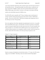
1
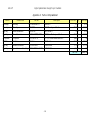
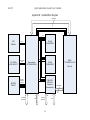
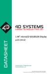
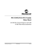
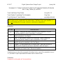
ECE 477
Digital Systems Senior Design Project
Spring 2009
Homework 3: Design Constraint Analysis and Component Selection Rationale
Due: Friday, February 6, at NOON
Team Code Name: Digi-iGuide
Group No. 11
Team Member Completing This Homework:
Greg Ross
E-mail Address of Team Member:
[email protected]
NOTE: This is the first in a series of four “professional component” homework assignments,
each of which is to be completed by one team member. The body of the report should be 3-5
pages, not including this cover page, references, attachments or appendices.
Evaluation:
SCORE
10
9
8
7
6
*
DESCRIPTION
Excellent – among the best papers submitted for this assignment. Very few
corrections needed for version submitted in Final Report.
Very good – all requirements aptly met. Minor additions/corrections needed for
version submitted in Final Report.
Good – all requirements considered and addressed. Several noteworthy
additions/corrections needed for version submitted in Final Report.
Average – all requirements basically met, but some revisions in content should be
made for the version submitted in the Final Report.
Marginal – all requirements met at a nominal level. Significant revisions in
content should be made for the version submitted in the Final Report.
Below the passing threshold – major revisions required to meet report
requirements at a nominal level. Revise and resubmit.
* Resubmissions are due within one week of the date of return, and will be awarded a score of
“6” provided all report requirements have been met at a nominal level.
Comments:
Comments from the grader will be inserted here.
ECE 477
Digital Systems Senior Design Project
Spring 2009
Section 1 - Introduction
The basic functionality would have the user input a destination and the device will determine the
user’s current position with a GPS module, and calculate the shortest path. The device will
display this information to the user on an LCD screen as a map overlaid with the path. The
device will also provide the user with information about points of interest. The features that will
cause design constraints include the graphics, the GPS, and the calculation of the user’s path to
the destination.
Section 2 – Design Constraint Analysis
The major design constraints that will be considered are the computational and interfacing
requirements. We are implementing a shortest path algorithm, and we’ll need to store a
significant amount of information in memory, so our MCU will need to have solid computing
capabilities.
Section 2.1 – Computation Requirements
The software for the Digi-iGuide will be computationally demanding both from the memory and
operating speed standpoints. We will compute the shortest path to the user’s destination using a
graph data structure, and if we assume a worst case scenario where we keep track of the graph’s
edges in a table (2-D array), we will need to store one 8-bit value for each possible edge (even
unconnected edges). If we have 150 nodes in our graph, this would be about 23 KB of data in
memory. This again is a worst-case scenario, and we plan on storing edges in a much more
efficient linked-list implementation, but we would still like to have a very large amount of onchip memory. We also anticipate that operational speed will need to be as high as possible due
to the large software computations, however since we do not have to consider issues such as
minimum sampling frequencies; we have no hard numbers for processor speed.
Section 2.2 – Interface Requirements
The Digi-iGuide’s only method of interfacing with the user is though an LCD Touch Screen
device. As a handheld device, the most appropriate screen size will be between 3” and 4” with a
resolution at or around 320 x 240 pixels. During the parts search, two components were located
that could suit the needs of the project. One 4.3” touch screen from Newhaven had a 480 x 272
-2-
ECE 477
Digital Systems Senior Design Project
Spring 2009
pixel touch screen and required a parallel LVDS (low voltage differential signal) interface that
would constantly refresh the screen at a frequency of 60Hz. This component had no graphics
controller included, and recommended the use of a graphics controller that was no longer being
manufactured [1]. The other component was a 3.2” touch screen from 4D Systems that came
with a 320 x 240 pixel touch screen integrated with a proprietary graphics controller. The
graphics controller has built in functionality to interface with a FAT16 formatted micro-SD
cards, read and output WAV audio files, transmit graphical data to the LCD, as well as read back
and decode the touch screen data. The 4D System unit included the touch screen, graphics
controller, micro-SD slot, on-board speaker, and a UART connection all in one PCB package [2].
If the final design included the Newhaven display, a graphics controller would (most likely) have
to be implemented in an FPGA which would significantly decrease the feasibility of the project.
The 4D System LCD unit (Part No: LCD-32032-P1T) included many useful features, but the
documentation recommends the use of a high speed UART operating at 512K-baud or 1M-baud
[2]. The team made the decision that the 4D System part was much better for the project needs,
though it did introduce a major constraint on processor selection and cost nearly twice as much
as the Newhaven display. The main processor must either have an on-board high speed UART,
or be electrically fast enough to allow software emulation of a 1M-baud UART by toggling
output pins.
The LCD-32032-P1T can interface with another microprocessor through a 3.3V CMOS UART
with baud rates ranging from 4800 baud to 1M-baud. For any input signal to be registered as a
logic low (including the UART pins) the maximum voltage must not exceed 0.7V, and the
minimum input high voltage is 2.6V. Output pins guarantee a maximum output low voltage of
0.4V and a minimum output high voltage of 2.6V [2].
The Digi-iGuide needs to be able to track the user’s location, thus a GPS unit is required.
Previous teams that utilized GPS technology were able to easily interface with the GlobalSat
EM-406a GPS receiver that utilizes a standard 4800 baud UART. The amount of data available
for this chip is limited, but GlobalSat’s specification sheet identifies the UART as utilizing TTL
logic levels. Maximum logic low voltage levels nor minimum logic high voltage levels are
-3-
ECE 477
Digital Systems Senior Design Project
Spring 2009
available for either the RX or TX lines of the UART. However, various portions of the
specification sheet hint that the TTL output logic levels are around 0V (low) and 2.85V (high)
and the inputs are 3.5V tolerant [3].
Finally, the user and developers need a way to re-program the device to support new maps or
updated maps. This will be done via an external USB port that must be connected either to the
microprocessor’s USB I/O or connected to a peripheral chip that provides USB functionality.
Based on the experience of some team members, the Silicon Laboratory’s C8051F320 USB
MCU will be placed on the PCB board to provide an off-chip USB port. The C8051F320 can
communicate with the main microprocessor via an SPI bus. The C8051F320 has tentatively
been identified to support 3.3V CMOS logic interfaces that are 5V tolerant, but no additional
documentation on voltage and current requirements are available in the data sheet. The
C8051F320 also has enough spare pins that it could also function as an SPI based port expansion
module if the need arises [4, 5].
Section 2.3 – On-Chip Peripheral Requirements
Our design requires the use of a relatively large number of on-chip peripherals. The GPS
module requires a standard UART while the LCD module requires a high speed UART. A
background debug UART is not required given the JTAG interface is available for debugging,
but the GPS UART’s RX line (TX from the microprocessor’s point of view) could be used as an
output-only debug UART if needed. A minimum of two UARTs are required, with three being
preferred.
Since we will be storing large image files and look-up-tables, the microprocessor needs
additional off-chip flash memory. To minimize the pin requirements, the SPI bus already needed
for the C8051F320 will be utilized along with a few GPIOs for slave select lines. If external
memory is needed for the software algorithms being implemented on the device, a parallel
SRAM or SDRAM interface would also be preferred on the main microprocessor and would use
up approximately 30 I/O pins.
Section 2.4 – Off-Chip Peripheral Requirements
-4-
Digital Systems Senior Design Project
ECE 477
Spring 2009
As previously mentioned, flash storage will be required in order to store the massive amounts of
data needed by the device. The largest flash chips with an SPI bus that are available have an
upper capacity limit of 64Mbit [6], and the team’s first assessment indicates that at least 8090Mbit of flash storage will be needed. So the device will require no less than two SPI flash
modules each with individual capacities of 64Mbit or more.
The GPS UART must be compatible with TTL logic, which may require a small amount of
circuitry to interface with the main microprocessor if the UART is actually a CMOS family
interface. Likewise, the LCD UART is CMOS based and might require supporting circuitry if
the UART pins are of the TTL logic family.
Due to the complexity of the software algorithms being implemented on the device, it is possible
that external SRAM will be required. Given that there is no known requirement yet for SRAM
capacity, the larger the chip the better but at the same time must use as few pins as possible while
being reasonably fast. An evaluation on the available I/O pins on every microprocessor being
considered indicates that there are not enough pins available to interface with the microprocessor
direction, and the C8051F320 will have to be used to provide port expansion as well.
Section 2.5 – Power Constraints
Part
Voltage (Min, Max)
Max Current Draw
SRAM CY7C1049DV33 [7]
3.0V, 3.6V
80mA
Flash W25X64VZEIG [6]
2.7V, 3.6V
25mA
PIC32MX440F512H [8]
2.3V, 3.6V
75mA
C8051F320 [5]
2.7V, 5.25V
18mA
GlobalSat EM-406A GPS [3]
4.5V, 6.5V
60mA
LCD-32032-P1T [2]
4.5V, 5.5V
100mA
Table 2.2.1 – Summary of Datasheet Power Specifications
Based on a summary of the datasheets in the table shown above a 3.3V power rail will be used to
supply power to the SRAM, 2 flash chips, main microcontroller and the USB peripheral
-5-
ECE 477
Digital Systems Senior Design Project
Spring 2009
microcontroller. A 5V power rail is required to power the GPS module and the LCD screen.
Since the nominal voltage for the battery suggested by the course staff (UBBP01) is 3.7V [9],
one regulator is required to step-down the power to 3.3V and another regulator system is
required to step-up the 3.7V input to 5V.
In total about 205 mA will be drawn from the 3.3V power rail and 160mA from the 5V rail. The
battery has a capacity of 1800mA hours, which should provide about 5 hours of battery life.
Since the battery requires at least 180mA current to charge and one USB port can supply
500mA, we cannot power the device and the charge the battery at the same time [9]. Either
portions of the device will have to be selectively shut off when charging the battery or a wall
wart solution will be required.
Section 2.6 – Packaging Constraints
The device needs to be small enough to carry and comfortable enough to hold. The material of
choice for the packaging will most likely be molded plastic since it is light weight has no effect
on the GPS signal, unlike metallic material like aluminum. The device should be tough enough
to withstand a fall from eye-level, but still not bulky.
Section 2.7 – Cost Constraints
The biggest cost constraint will be the LCD screen, which optimally will support touch. The
LCD screens that would suit our desires are around $200, however we 4D Systems is willing to
sample this part for us, so we do not anticipate having to pay for it. Our only other significant
expenses are the GPS module and possibly a development board. The GPS units we have looked
at range from $50 to $100, and a development board would cost around $50. While not
necessary, we see the development board as the best way to get an early start on our project.
There are currently no devices that fill our market niche, however our product is similar in nature
to a device such as a Tomtom One 130S, which has a MSRP of $199.
-6-
Digital Systems Senior Design Project
ECE 477
Spring 2009
Section 3.0 – Component Selection Rationale
Our first major component comparison is our MCU. We will consider two processors, the
PIC32MX440F512, and the Freescale MCF5249. The major decision categories are listed in the
table below, along with the performance metrics for each chip. We are choosing a chip with a
“worst case scenario” mindset, which is to say that in the worst case scenario we may need to use
a RAM interface, so we prefer a chip that allows us to do so.
Metric
PIC32MX440F512 [8]
Freescale MCF5249 [10]
Frequency
80 MHz
120 MHz
Package
64-TQFP
144-QFP
On-board FLASH
512 KB
None
On-board RAM
32 KB
96 KB
RAM Interface
SRAMz
SDRAM
High-Speed UART
1 @ speeds up to 20 Mbit
None
Total UARTs
2
2
Total SPI
1
1
USB Interface
Yes
None
Debug Interface
JTAG
JTAG
Development Tools
Familiar to our group
Unfamiliar to our group
While it is possible that we may not end up needing to use all of the chip’s features, for example
we may not need all 512 KB of onboard flash, we would strongly prefer to have the option
available. With this in mind the PIC32 appears to be the best choice for an MCU.
In addition to the MCU, our LCD display will be a major component. Our LCD was not nearly
as close of a comparison, since we were unable to find very many displays that fit our needs.
-7-
Digital Systems Senior Design Project
ECE 477
Metric
µLCD-32032-P1T [2]
Spring 2009
NHD Series LCD TFT [1]
Pixel Resolution
320 X 240
480 X 272
Touch Support
Yes
No
Integrated Controller
Yes
No
Cost
Free (by Sample)
$79.90
The µLCD-32032 is the clear winner. The potential downside is if a part of the display package
is broken during development, it could cost more to replace, however the replacement may still
be less than the $80 pricetag of the NHD Series.
Our final major component consideration is the GPS module. All of the modules we looked at
used the NMEA protocol for communication via a UART, so our selection criteria were
narrowed down to price and familiarity. We will use the GlobalSat module for cost efficiency.
Metric
GlobalSat EM-406a [3]
ETEK EB-85a [11]
Familiarity
Used by B.E.A.R.S. team
Used by Global Pigeon Team
Cost
$60
$90
Section 4.0 – Summary
As mentioned previously, our approach to component selection is to find components that give
us as many options as possible. We chose an MCU that will give us a great deal of flexibility in
implementation and has solid development tools for debugging and quick start-up. Our LCD
display has a build-in controller that will free-up MCU resources for other processing tasks. The
GPS module we have chosen is both relatively low cost, and it uses the industry standard NMEA
communications protocol.
-8-
ECE 477
Digital Systems Senior Design Project
Spring 2009
List of References
[1] NHD-4.3-480272YF-ATXI#-1 LCM (Liquid Crystal Display Module), rev. 003, Newhaven
Display, Elgin, IL, 2008
[2] LCD-32032-P1T USERS MANUAL, rev. 1.1, 4D Systems, Redwood City, CA, 2008
[3] EM-406a GPS RECEIVER ENGINE BOARD, rev. 1.1, GlobalSat, Taipei, Taiwan, 2006
[4] C8051F320 DATA SHORT, Silicon Labs, Austin, TX, 2006
[5] C8051F32x DATA SHEET, rev. 1.3, Silicon Labs, Austin, TX, 2008
[6] WINBOND SPI FLASH, rev. I, Winbond, Taipei, Taiwan, 2008
[7] CY7C1049DV33, rev. D, Cypress Semiconductor Corp, San Josa, CA, 2007
[8] PIC32MX3XX/4XX Family Data Sheet, rev. E, Microchip, Tempe, AZ, 2008
[9] UBBP01 TECHNICAL DATASHEET, rev. D, Ultralife Batteries, Newark, NY, 2006
[10] MCF5249 ColdFire® Integrated Microprocessor User’s Manual, rev. 4.0, Freescale, Austin,
TX, 2003,
[11] MTK-3301 GPS Receiver Series Model: FV–M8 GPS Receiver, rev. 070516, SANAV, San
Jose, CA, 2007
IMPORTANT: Use standard IEEE format for references, and CITE ALL
REFERENCES listed in the body of your report.
-9-
ECE 477
Digital Systems Senior Design Project Fall2008
Appendix A: Parts List Spreadsheet
Vendor
Microchip
Microchip
Digi-Key
Digi-Key
4D Systems
DCPAV
Manufacturer
Microchip
Microchip
Silicon Laboratories
Silicon Laboratories
4D Systems
GlobalSat
Part No.
PIC32MX440F512
DM320003
C8051F320
DEBUGADPTR1-USB
LCD-32032-P1T
EM-406A
Digi-Key
Digi-Key
Winbond Electronics
W25X64VSFIG
Cypress Semiconductor Corp CY7C1049DV33-10VXI
Description
32bit MCU
PIC32 Development Board
8bit USB MCU
C8051Fxxx Development Board
3.2” LCD Touch Screen with GPU
GPS Module
64-Mbit Flash
4-MB SRAM
Unit Cost Qty
2.5 3
55.95 1
7.8 1
35.00 1
(200) 1
59.95 1
8.78
(4.6)
TOTAL
-10-
2
2
Total Cost
$7.50
$55.95
$7.80
$35.00
$0
$59.95
$17.56
$0
$183.76
Digital Systems Senior Design Project Fall2008
ECE 477
Appendix B: Updated Block Diagram
SRAM DATA
8
SRAM CTRL LINES
SPI
GPS
EM-406a
LCD TOUCH
uLCD-32032-P1T
SS1
UART
HIGH SPEED
UART
Microcontroller
PIC32MX440F512H
FLASH
W25X64VZEIG
SS2
SRAM
CY7C1049DV33-10VXI
FLASH
W25X64VZEIG
(1Mb x 8)
BATTERY
CIRCUIT
BATTERY
CONTROL
SIGNALS
C8051F320
USB & Port
Expansion
Microcontroller
SS3
20
C8051_MODE
JTAG DEBUG
INTERFACE
USB
C2 DEBUG
INTERFACE
-11-
SRAM ADDR
USB