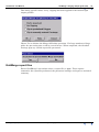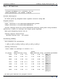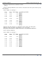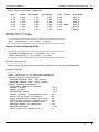
1
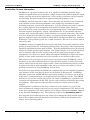
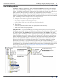
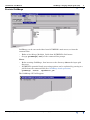
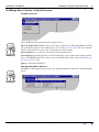
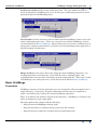
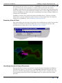
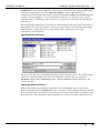
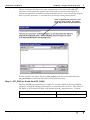
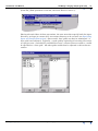
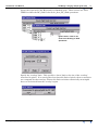
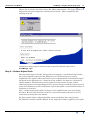
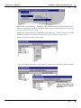
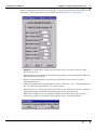
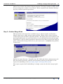
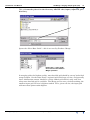
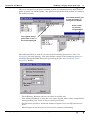
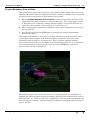
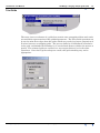
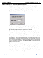
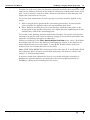
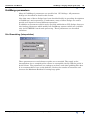
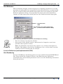
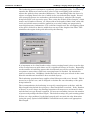
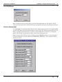
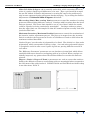
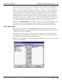
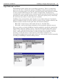
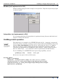
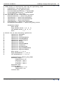
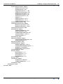
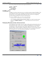
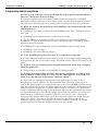
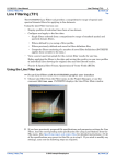
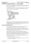
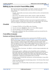
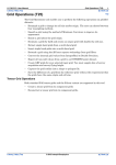
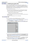
INTREPID User Manual
Library | Help | Top
GridMerge—merging multiple grids (T24)
1
| Back |
GridMerge—merging multiple grids (T24)
Top
Introduction to GridMerge
Overview
The GridMerge tool is an innovative tool that allows the simultaneous merging of a
large number of grids into a single, merged grid file. GridMerge is suitable for a wide
range of gridded data types, including potential field datasets (magnetics, gravity,
etc), topography and bathymetry. The scaling correction enables effective merging of
radiometrics grids.
The typical GridMerge process is illustrated below.
The sun-shaded image shown here is a GridMerge produced single grid of potassium
channel radiometrics data from the Pilbara in Western Australia. The grid was
generated from seven original grids.
Library | Help | Top
© 2012 Intrepid Geophysics
| Back |
INTREPID User Manual
Library | Help | Top
GridMerge—merging multiple grids (T24)
2
| Back |
Evaluation Licence Information
GridMerge is a powerful software tool. It is capable of combining together large
numbers of gridded datasets to produce a single merged and seamless grid file which
retains all of the detail of the input grids. A free 30-day evaluation can be arranged
by contacting Intrepid Geophysics at [email protected]
GridMerge was first released in 2000. Since that time the tool has been extensively
tested within several client organisations, often using large ensembles of grids,
including magnetics, gravity and radiometrics. It is the primary tool used to support
the on-going updates of the Australian Potential Field super-grids. These are
produced at least yearly and reflect the ever improving nature of the understanding
and observations of magnetics, gravity and radiometrics. A web-enabled interface
together with a multi-threading, cluster initiative is currently under way. The intent
is to drive down the time taken to achieve very high resolution super-grids. The 10
gigabyte magnetic map of Australia is taking about 100 hours in 2006 on a standard
desktop PC, using 700 base grids, for a 100m resolution. The aim is to achieve this in
3 hours by 2007
GridMerge performs complex data processing, and many factors will contribute to the
quality of output achieved. In merging grids together, the quality of the output grid is
naturally dependent on input grid qualities. Typically gridded datasets to be merged
will have variable quality and resolution. For optimal results, it is essential that the
user be familiar with all of the ‘quality issues’ in the grids being merged so that
appropriate user choices are made which will enable GridMerge to exploit the better
quality of some grids compared to the lesser quality or resolution of other grids.
This guide has been designed to assist users to get started with GridMerge, and to
learn how to use their understanding of input grid data quality to make processing
choices which achieve the best output results. Some experimentation may be needed
in order to develop an understanding of the effects of various user-choices, and to
build up experience in using GridMerge to best effect.
All of the main functionality of GridMerge is implemented in the simplified graphical
user interface (GUI), and those features are described in this manual. GridMerge,
like other parts of the INTREPID data processing package, can also be run in batch
mode from a command prompt, using parameters specified in a job file. The SHOW
button lets you see the current state of the job. Some of GridMerge’s capabilities are
currently not implemented in the GUI, but are only available in the batch processing
environment. Some aspects of the batch processing are briefly covered in this
manual.
GridmergePro is available for the more serious user who wishes to access all the
inner methods and settings of the tool via the a more compehensive GUI. Some access
to the more comprehensive menu options can be had by editing the install.cfg file
in the Intrepid config directory. The option to enable is the GRIDMERGE_MENU++.
Also supported in GridmergePro is the extra step of taking the final levelled signal
back to the original observed channels in line datsets. This can be thought of as a
“Super” micro-levelling option.
Library | Help | Top
© 2012 Intrepid Geophysics
| Back |
INTREPID User Manual
Library | Help | Top
GridMerge—merging multiple grids (T24)
3
| Back |
How GridMerge Works
GridMerge works by applying a range of level and surface corrections to multiple
grids that are linked by overlaps. An overlap is where two grids share a spatial
region. GridMerge statistically analyses the data within the overlap for each pair of
grids, and uses these results to compute the appropriate level and surface
adjustments for each grid. Once the grids have been adjusted to a common level and
surface, a feathering and merging operation amalgamates the grids into one seamless
grid. GridMerge can be thought of as a two-stage process:
1
Compute Corrections to generate Adjusted Grids
•
one or more separate correction processes
•
each of these write out a sub-directory of adjusted grids
2
Final Merge
•
uses the adjusted grid files from the appropriate sub-directory
•
writes out a final, merged grid file
IMPORTANT:. A typical GridMerge processing task requires several sequential
GridMerge operations, where each operation performs a specific phase of the overall
job, and frequently the output from one operation becomes the input to the next
operation. Since GridMerge is often applied to processing large numbers of grid files,
many GridMerge operations expect data to be organised in directories, and outputs
will be written to (separate, new) directories. The input and output (‘adjusted’) grid
files have the same file names , and thus the outputs must be written to a new
directory in order not to overwrite the input files. A systematic approach to using
directories is essential. A typical directory structure after using GridMerge is
illustrated below. Note that the raw input grids, and the various intermediate stages
of ‘adjustment’ are all contained within separate directories. Additionally there is the
final merged grid file. (See Specifying Input and Output Directories for further
details of directory specification).
Library | Help | Top
Grids Sub-directory.
DC-Corrected
Grids Sub-directory.
Surface-Adjusted (and
DC-Corrected)
Grids Sub-directory.
Original data
Final merged grid
© 2012 Intrepid Geophysics
| Back |
INTREPID User Manual
Library | Help | Top
GridMerge—merging multiple grids (T24)
4
| Back |
Execute GridMerge
GridMerge can be executed either from INTREPID’s main menu, or from the
command line.
•
Either select Merge_Multiple_Grids from INTREPID’s Grid menu.
•
Or type gridmerge(.exe) at the command line prompt
Notes:
•
Before starting GridMerge, first browse to the directory above the input grid
directory.
•
INTREPID’s powerful batch processing options can be exploited by passing in a
job file from the command line (See GridMerge batch operation)
gridmerge –batch
MyJobFile.job
The GridMerge GUI will appear.
Library | Help | Top
© 2012 Intrepid Geophysics
| Back |
INTREPID User Manual
Library | Help | Top
GridMerge—merging multiple grids (T24)
5
| Back |
GridMerge Menu Choices—a Quick Overview
File Menu Choices
The GridMerge File menu has four simple choices.
Specify Report File allows the user to enter a filename to which GridMerge writes
any processing reports. See further notes in GridMerge report files The two ‘options’
choices allow the user to save the current processing settings
Save Options), or to load in a file of processing parameters
Load Options) which may have been saved during some earlier processing session.
(Use of INTREPID job files is also covered in Batch Processing—Section GridMerge
batch operation). Use
Quit to exit from GridMerge.
Grid Operation Menu Choices
GridMerge’s main processing choices are grouped together under the Grid Operation
menu.
Library | Help | Top
© 2012 Intrepid Geophysics
| Back |
INTREPID User Manual
Library | Help | Top
GridMerge—merging multiple grids (T24)
6
| Back |
PreProcess Grids provides some utility functions. The user might use these to
assist in planning a GridMerge job, or to do some pre-conditioning operations to the
input grids prior to GridMerging them.
Level Grids has three sub-menu choices which provide GridMerge’s three level and
surface adjustment processes. These are core processes within GridMerge, and are
covered in detail in Basic GridMerge. Each of these processes reads a sub-directory of
input grids, computes adjustments, and writes out corresponding output grids into a
specified output sub-directory.
Merge Grids has two menu choices for doing the final GridMerge operation—viz.
reading input from a sub-directory of (levelled & surface adjusted) grids, and
combining these into one final seamlessly merged output grid file. This is the second
of GridMerge’s two main processes, and is discussed in detail in Basic GridMerge.
Basic GridMerge
Preparation
GridMerge requires all of the grids that are to be merged be collected together into a
single directory. Conversely, all grids within that sub-directory are regarded as
‘input’, and will be processed by the chosen GridMerge operation.
There is no limit to the number of grids in this directory. GridMerge is routinely run
with one hundred or more input grids.
The input grids must comply with the following:
Library | Help | Top
•
All grids must be ERMapper format grids
•
All grids must have a common datum, projection and rotation
•
All grids must be ‘linked’ by overlaps between individual grids
© 2012 Intrepid Geophysics
| Back |
INTREPID User Manual
Library | Help | Top
GridMerge—merging multiple grids (T24)
7
| Back |
Individual grids may have any cell size. INTREPID’s Projection Conversion tool can
be used if necessary to bring grids to a common datum, projection & rotation.
GridMerge uses the areas of overlap between grids to determine the adjustments that
need to be made, so it is self-evident that overlaps must ‘connect’ all grids together in
order for GridMerge to achieve the goal of computing corrections to bring all grids to a
common level and surface.
GridMerge also has some utility operations (Grid Operation | PreProcess Grids)
which may be used to modify the grids in some way that might allow for improved
application of GridMerge. (See GridMerge utility operations)
Boundary View of Grids
One of the utility processes does not generate any modifications to grids, but provides
a handy visualisation tool which permits the user to visualise the extent of the
overlaps between grids. (See Prepare Boundary View of Grids
Specifying Input and Output Directories
The specification of inputs and outputs is mainly identical throughout GridMerge.
Typically the input is a sub-directory, and all grids within that sub-directory are
processed. For the ‘adjustment’ operations, the output is also a sub-directory, and
corresponding adjusted grid files of the same name are written into that output
directory.
Library | Help | Top
© 2012 Intrepid Geophysics
| Back |
INTREPID User Manual
Library | Help | Top
GridMerge—merging multiple grids (T24)
8
| Back |
WARNING: For all of GridMerge’s ‘adjustment’ operations, the input grids and the
‘adjusted’ output grids have the same file names. If the same directory is
nominated for both input and output, then the input files will be overwritten by the
output ‘adjusted’grid files. It is recommended that the user specify a new output
(sub-)directory. GridMerge will create the new directory, and write the output grid
files into it
Recommended good practice is to keep the intermediate grid files from each stage of
processing. The user may choose to do some reprocessing, with modified processing
specifications—using one of the saved intermediate ‘adjusted’ grids as the
appropriate starting point.
Specifying Input Directory
Browse to the directory containing the input grids to be processed. For UNIX simply
select the required (input) directory. For Windows, the file-chooser requires a
filename rather than a directory name. Browse into the (input) directory, and
choose any file.
Specifying Output Directory
Immediately after specifying the input directory, GridMerge pops up a message
(below) advising that an output directory is required. This (output) directory should
be a new directory, and must be at the same level as the input directory, never a subdirectory of it. The ‘adjusted’ output grid files are written into this output directory.
Library | Help | Top
© 2012 Intrepid Geophysics
| Back |
INTREPID User Manual
Library | Help | Top
GridMerge—merging multiple grids (T24)
9
| Back |
Choose an output sub-directory name appropriate to the selected GridMerge
operation. Frequently the output from a given process becomes the input to a
subsequent operation. Sensible naming of the directories - each containing outputs
from a specific operation - is essential for careful processing management.
Enter an appropriate name for a new
directory to be created. The output
grids will be written to this directory
In this example, the input directory (raw_input) and the new output directory
(dc_shifted) are both sub-directories of the grids directory.
Step 1—DC_Shift (or Scale then DC_Shift)
The first GridMerge operation to be applied is usually a Shift (or Scale-and-Shift)
operation, designed to bring all datasets to a common scale and level. The choice of
DC-Shift, or Scale-then-DC-Shift, will depend upon the input datasets. Usually:
Library | Help | Top
Potential field data (magnetics, gravity)
use DC_Shift
Radiometrics data
use Scale_THEN_DC_Shift
© 2012 Intrepid Geophysics
| Back |
INTREPID User Manual
Library | Help | Top
GridMerge—merging multiple grids (T24)
10
| Back |
(If the DC_Shift operation is selected, the Scale Factor is set to 1).
Having selected either of these operations, the user must then specify both the input
directory, and type in a name for a new output directory to be created. (see Specifying
Input and Output Directories)" One or more ‘base’ grids can then be nominated. A
base grid is not adjusted. Typically, a good quality regional grid covering all or most
of a project area—and which is considered to have a correct reference surface—would
be specified as a ‘base grid’. All other grids would then be adjusted to this reference
surface.
Library | Help | Top
© 2012 Intrepid Geophysics
| Back |
INTREPID User Manual
Library | Help | Top
GridMerge—merging multiple grids (T24)
11
| Back |
Ignore the requests for the High and Low Ranked grids. These criteria are NOT
USED in either the DC_Shift or the Scale_then_DC_Shift operations.
Ignore these—rank is not
used in the Scaling or Shift
operations
Specify the ‘overlap’ limit. This specifies a lower limit to the size of the ‘overlap’,
measured in pixels. If an overlap has less than this limit of pixels, then no statistics
are computed for that overlap. Choose this limit such that statistically meaningful
data can be derived from the ‘overlap’ region.
Library | Help | Top
© 2012 Intrepid Geophysics
| Back |
INTREPID User Manual
Library | Help | Top
GridMerge—merging multiple grids (T24)
12
| Back |
Choose Yes to initiate the (Scale-then) DC_Shift computations. For large numbers of
large grids, the processing time could be several hours. When completed, this
message pops up.
A brief processing report is written to the report file (default report file is
GridMerge.rpt)
Step 2—Surface Adjust Grids
This operation inspects all the input grids and computes a two dimensional surface
for each grid which represents the differences in Z values between it and its
neighbours. The surface takes the form of a pair of polynomials of the defined degree,
one fitted to the differences as a function of row number, the other as a function of
column number. The difference surface with the largest mean Z value is then
subtracted from its corresponding grid. The process iterates until the largest mean Z
value of all difference surfaces falls below a given threshold, or a maximum number of
iterations is exceeded.
Note : 1 dimensional polynomials of degree N are applied in the row and column
direction. Because the iteration is done in a piecewise manner, the lack of an XY
cross-term generally does not matter.
For best results Surface Adjust should be run on grids that have already been
DC_Shifted or Scaled and DC_Shifted. If not, large tilts could be applied to the grids.
Library | Help | Top
© 2012 Intrepid Geophysics
| Back |
INTREPID User Manual
Library | Help | Top
GridMerge—merging multiple grids (T24)
13
| Back |
Specify the input directory. Normally a DC_Shift has been done previously, and
those saved outputs would be specified as the input to Surface Adjust. (Specifying
Input and Output Directories)
Again, the output directory is normally a new directory. Type in a name for a new
output directory to be created. (Specifying Input and Output Directories)
Again, specify one or more ‘base’ grids.
—but the ranking selections can be ignored—these are not used by Surface Adjust.
Ignore these. Rank is not
used in the Surface Adjust
operations
Library | Help | Top
© 2012 Intrepid Geophysics
| Back |
INTREPID User Manual
Library | Help | Top
GridMerge—merging multiple grids (T24)
14
| Back |
Surface Adjustment requires user input for a series of parameters which control the
operation. These parameters are described in detail in Surface Adjustment.
Library | Help | Top
•
Allow DC, if unchecked, constrains the mean value of a surface fitted to grid
differences to zero
•
Overlap limits constrains the number overlap points used in fitting the difference
surface between two grids
•
Max Iterations & Residual control the termination of the iterative surface
adjustment process.
•
Order of polynomial used in fitting the surface. Default = 1 (ie. slope adjustment),
but a second order polynomial (= 2) can be useful.
•
Degree Limits (%) ensure that surfaces fitted to the differences in the overlap are
meaningful when compared to the full extent of the grids involved.
•
Differences Limit sets a rejection limit. Differences observed in the overlap
between two grids are rejected if the absolute value exceeds this limit.
© 2012 Intrepid Geophysics
| Back |
INTREPID User Manual
Library | Help | Top
GridMerge—merging multiple grids (T24)
15
| Back |
Choose Yes to initiate the Surface Adjust operation. For large numbers of large grids,
the processing time could be several hours. When completed, the ‘finished’ message
pops up, and the report file presented.
Step 3—Feather Merge Grids
This operation reads input from a subdirectory of ‘adjusted’ grids and ‘Feather /
Merges’ them into a single merged output grid file. Merge selects values from the
various input grids to build a composite grid file. The input grids can be ranked, such
that high ranked grids are used in preference to low ranked grids during the merging.
Feathering is a process which attempts to smooth out any ‘sharp’ steps at the edges of
grids, such that the final grid file has no ‘join’ artefacts (ie. a seamless final grid file
is produced).
Specify the input directory. Normally some DC_Shift and Surface Adjustments will
have been done previously, and the saved outputs would be specified here as the
input to Feather/Merge. (See Specifying Input and Output Directories)
The output required for Feather/Merge is simply a name for the final, merged grid
file.
Library | Help | Top
© 2012 Intrepid Geophysics
| Back |
INTREPID User Manual
Library | Help | Top
GridMerge—merging multiple grids (T24)
16
| Back |
This grid must be placed in the directory ABOVE the (input) ‘adjusted’ grid
directory.
Ignore the ‘Select Base Grids’ —this is not used by Feather / Merge.
Ignore this— ‘base grids’
is not used in the Feather /
Merge operation
In merging grids, the highest quality, most detailed grid should be ‘on top’ in the final
merged output. On the other hand, a regional grid with large cell size, and generally
lower ‘information content’ should be a lowly ranked grid which is only used if no
other more detailed grid is available. The Merge process uses a default ranking; the
smallest input grid cell size is highest ranked. For a given cell size, the input grid
with most data points ranks highest.
Library | Help | Top
© 2012 Intrepid Geophysics
| Back |
INTREPID User Manual
Library | Help | Top
GridMerge—merging multiple grids (T24)
17
| Back |
The user can specify a preferred ranking of grids, by nominating both ‘high ranked’
grids, and also ‘low ranked’ grids. Any grids not specified will be ranked according to
the default criteria.
The ‘lowest ranked’ grid
is used only when no
other grid is available.
Enter a name
for the final,
merged output
The ‘highest ranked’
grid will be ‘on top’ in
the final merged grid
The following dialog is used to set some of the feathering parameters. (See Grid
Feathering for more details). Note that further control of the feathering process is
available through INTREPID’s batch processing job files (see GridMerge batch
operation) Briefly:
Library | Help | Top
•
Check Memory Resident for fast execution of smaller jobs
•
Trim allows GridMerge to trim the very edges of grids, where some extrapolation
during gridding may result in less accurate grid values
•
Overlap limit specifies a minimum number of points in an overlap between two
grids
•
Filter length can be increased to increase the amount of smoothing
© 2012 Intrepid Geophysics
| Back |
INTREPID User Manual
Library | Help | Top
GridMerge—merging multiple grids (T24)
18
| Back |
This dialog specifies what, if any, clipping should be applied to the final merged
output grid file.
Choose Yes to initiate the Merge & Feather operation. For large numbers of large
grids, the processing time could be several hours. When completed, the ‘finished’
message pops up, and the report file presented.
GridMerge report files
Each of GridMerge’s operations writes a report file (*.rpt). These reports
summarise the operation performed, the parameter settings and report a statistical
summary.
Library | Help | Top
© 2012 Intrepid Geophysics
| Back |
INTREPID User Manual
Library | Help | Top
GridMerge—merging multiple grids (T24)
19
| Back |
Step 1—DC Shift Grids
****************************************************
Intrepid GridMerge v3.5 (release) cut 101
Start processing - 10/ 3/2001 6:28:40
****************************************************
Process description
------------------DC shift grids by weighted least squares solution using SVD
Program Control
--------------Input directory C:/nt_data/agso/gmerge/part_pilbra
Output directory C:/nt_data/agso/gmerge/j1
Initial overlap shift and scales determined directly from grids using standard
deviations & means of overlaps and output grids adjusted.
Base grid weighting factor 200.00
Overlap regions restrictions.
Minimum overlap size : 500 pixels
Processing Summary
-----------------Grid sequence for processing
1 p497_k p507_k p508_k p509_k p510_k p513_k p656_k
Overlap statistics
Total number of overlaps in island 1 is 7
no points
1536
Grid1
Mean Stnd Dev %ovlp
0.60
0.40
0.6
2020
1.11
0.50
0.7
2259
1.42
0.69
0.8
5713
0.85
0.52
11.3
1018
1.07
0.46
2.1
5943
0.62
0.29
2.3
2600
0.96
0.40
1.0
Grid2
Mean Stnd Dev %ovlp gridname1/gridname2
0.64
0.49
3.1 p497_k:1
p508_k:1
1.13
0.52
1.1 p497_k:1
p510_k:1
1.43
0.83
3.5 p497_k:1
p656_k:1
0.87
0.47
2.2 p507_k:1
p509_k:1
1.08
0.56
1.6 p508_k:1
p656_k:1
0.59
0.31
3.1 p509_k:1
p510_k:1
1.08
0.46
4.0 p509_k:1
p513_k:1
No base grid defined via program control.
Library | Help | Top
© 2012 Intrepid Geophysics
| Back |
INTREPID User Manual
Library | Help | Top
GridMerge—merging multiple grids (T24)
20
| Back |
Selection algorithm has therefore chosen
p510_k
Initial overlap summaries to be used to calculate the final grid shifts by LSQ
SVD analysis
Total number of overalps 7
scale
1.000
shift
0.041
mean2-mean1
0.04
1.000
0.021
0.02
1.000
0.011
0.01
1.000
0.019
0.02
1.000
0.005
0.01
1.000
-0.030
-0.03
1.000
0.118
0.12
gridname1/gridname2
p497_k
p508_k
p497_k
p510_k
p497_k
p656_k
p507_k
p509_k
p508_k
p656_k
p509_k
p510_k
p509_k
p513_k
Applying LSQ SVD analysis to determine final shifts for each grid.
Applying scale and shift adjustments to all grid data.
All grids transcribed to output directory C:/nt_data/agso/gmerge/j1
Final overlap summaries
Total number of overlaps 7
scale
1.000
shift
0.021
mean2-mean1
0.01
1.000
0.021
0.00
1.000
0.021
-0.01
1.000
-0.011
0.00
1.000
-0.008
0.01
1.000
-0.030
-0.00
1.000
-0.030
-0.00
Library | Help | Top
gridname1/gridname2
p497_k
p508_k
p497_k
p510_k
p497_k
p656_k
p507_k
p509_k
p508_k
p656_k
p509_k
p510_k
p509_k
p513_k
© 2012 Intrepid Geophysics
| Back |
INTREPID User Manual
Library | Help | Top
GridMerge—merging multiple grids (T24)
21
| Back |
Final grid adjustment summaries
Shift
0.02
-0.01
-0.01
-0.03
-0.00
-0.15
-0.00
Scale
1.000
1.000
1.000
1.000
1.000
1.000
1.000
BeforeMean
0.55
0.94
0.83
0.88
0.82
0.83
1.16
AfterMean
0.57
0.92
0.82
0.85
0.82
0.68
1.16
diff
0.02
-0.01
-0.01
-0.03
0.00
-0.15
-0.00
Status
BASE
Grid Name
p497_k
p507_k
p508_k
p509_k
p510_k
p513_k
p656_k
Elapsed time is 0:0:10
CPU time is 0:0:1.#QNAN0
****************************************************
End
processing - 10/ 3/2001 6:28:50
****************************************************
Step 2—Surface Adjusted Grids
****************************************************
Intrepid GridMerge v3.5 (release) cut 101
Start processing - 10/ 3/2001 6:31:38
****************************************************
Process description
------------------Level grids by fitting polynomial surfaces to overlap differences.
Program Control
--------------Input directory C:/nt_data/agso/gmerge/j1
Output directory C:/nt_data/agso/gmerge/j2
Overlap regions restrictions.
Minimum overlap size : 500 pixels
Maximum overlap size : 5000 pixels
Surface fitting parameters.
Polynomial degree of surface
: 1
Degree 1 Limit
: 20.0
Degree N Limit
: 90.0
Differences Limit
: 99.0
Reject outliers in polynomial fits : NO
Allow net DC shift of surface
: NO
Apply degree zero surface fit first : NO
Use row and column averages in fit : NO
List fitted surface coefficients
: NO
Maximum number of iterations
: 100
Maximum residual
: 0.050
Point limit for weight of 1.0
: 10
Library | Help | Top
© 2012 Intrepid Geophysics
| Back |
INTREPID User Manual
Library | Help | Top
GridMerge—merging multiple grids (T24)
22
| Back |
Processing Summary
-----------------Grids selected for surface adjustment
------------------------------------1 p497_k p507_k p508_k p509_k p510_k p513_k p656_k
List of overlaps for each grid
-----------------------------Seq Grid
No Overlaps
(Grid Overlap Pair, Number Overlap Points)
1
p497_k
3
1 p508_k,1516 p510_k,2013 p656_k,2229
Total number of overlap points 5758
2
p507_k
3
1 p509_k,2815 p510_k,48 p513_k,20
Total number of overlap points 2883
3
p508_k
2
1 p497_k,1516 p656_k,1008
Total number of overlap points 2524
4
p509_k
3
1 p507_k,2815 p510_k,2924 p513_k,2564
Total number of overlap points 8303
5
p510_k
3
1 p497_k,2013 p507_k,48 p509_k,2924
Total number of overlap points 4985
6
p513_k
2
1 p507_k,20 p509_k,2564
Total number of overlap points 2584
7
p656_k
2
1 p497_k,2229 p508_k,1008
Total number of overlap points 3237
Total number of overlaps found 9
Library | Help | Top
© 2012 Intrepid Geophysics
| Back |
INTREPID User Manual
Library | Help | Top
GridMerge—merging multiple grids (T24)
23
| Back |
Fitting degree 1 polynomials
---------------------------Iteration
Max Adjustment
Grid
p497_k
mean =
0.193 X fit =
change =
0.000
p507_k
mean =
0.194 X fit =
change =
0.008
p508_k
mean =
0.186 X fit =
change = -0.000
p509_k
mean =
0.135 X fit =
change = -0.000
p510_k
mean =
0.115 X fit =
change =
0.000
p513_k
mean =
0.120 X fit =
change =
0.004
p656_k
mean =
0.223 X fit =
change =
0.001
-0.667 Y fit =
-0.183 mean2 =
0.193 diff
14.753 Y fit =
-0.000 mean2 =
0.187 diff
-1.259 Y fit =
-0.172 mean2 =
0.187 diff
-2.315 Y fit =
0.434 mean2 =
0.135 diff
-0.221 Y fit =
0.036 mean2 =
0.115 diff
15.032 Y fit =
-1.908 mean2 =
0.117 diff
3.273 Y fit =
0.717 mean2 =
0.223 diff
Applying 2D Polynomial Surface adjustments of degree 1 to output grids.
Grid Correction Summary
----------------------List of corrections applied to each grid via Surface Adjustment
and statistics on the final overlap differences.
(Corrections listed below were added to the original grids).
Ref
CORRECTIONS
FINAL
Seq Count
Mean
Minimum
Maximum Mean
1
0
0.000
0.000
0.000
0.002
2
0
0.000
0.000
0.000
0.001
3
0
0.000
0.000
0.000
-0.001
4
0
0.000
0.000
0.000
-0.001
5
0
0.000
0.000
0.000
0.001
6
0
0.000
0.000
0.000
0.001
7
0
0.000
0.000
0.000
-0.004
OVERLAP DIFFERENCES
sd
Minimum
Maximum Grid
0.252
-0.964
1.032 p497_k
0.251
-0.840
0.920 p507_k
0.242
-0.749
0.807 p508_k
0.185
-0.920
0.840 p509_k
0.153
-0.543
0.555 p510_k
0.158
-0.589
0.577 p513_k
0.282
-1.032
0.964 p656_k
Elapsed time is 0:0:10
CPU time is 0:0:1.#QNAN0
****************************************************
End
processing - 10/ 3/2001 6:31:48
****************************************************
Library | Help | Top
© 2012 Intrepid Geophysics
| Back |
INTREPID User Manual
Library | Help | Top
GridMerge—merging multiple grids (T24)
24
| Back |
Step 3—Feather Merge Grids
****************************************************
Intrepid GridMerge v3.5 (release) cut 101
Start processing - 10/ 3/2001 6:33:32
****************************************************
Process description
------------------Seamless feather and merge grids into a single grid.
Program Control
--------------Input directory C:/nt_data/agso/gmerge/j2
Output grid C:/nt_data/agso/gmerge/f1
Output grid parameters are.
X origin
:
115.680000
Y origin
:
-20.485000
X cell size :
0.001000
Y cell size :
0.001000
Processing Summary
-----------------Grid ranking for feathering (low to high).
Each grid is overlayed by those that follow it in this list.
1 p508_k p507_k p513_k p510_k p509_k p497_k p656_k
Elapsed time is 0:5:20
CPU time is 0:0:1.#QNAN0
****************************************************
End
processing - 10/ 3/2001 6:38:52
****************************************************
GridMerge utility operations
GridMerge has some additional utility processes to assist in planning a GridMerge
job, or to do some pre-conditioning operations to the input grids prior to GridMerging
them.
Library | Help | Top
© 2012 Intrepid Geophysics
| Back |
INTREPID User Manual
Library | Help | Top
GridMerge—merging multiple grids (T24)
25
| Back |
Prepare Boundary View of Grids
This utility process generates a ‘special’ copy of the grid files which allow the user to
visualise the extent of the overlaps between grids. A series of simple steps are needed
to generate the visual picture of grid extents and overlaps.
1
Execute Prepare Boundary View of Grids As with several other operations, the
output grids should be written to a new sub-directory. The output grids created
by this process are assigned a unique integer number—each grid’s Z values are
replaced by this number. (thus a grid of 1s, a grid of 2s, etc)
2
Run a simple merge operation to composite these ‘special’ grids into one merged
‘special’ grid file.
3
Load the merged grid into ERMapper to visualise the spatial relationships
between the grids.
This simple visualisation can be used to rapidly identify any grids with little or no
overlap with adjacent grids. Note that the number assigned to each grid is the
sequential order in which it was processed. These sequence numbers and the
associated grid file names are tabulated in the processing report file, so a grid name
can be determined by querying the Z value of a grid in ERMapper, and crossreferencing to the list of grid names.
Intrepid Geophysics has a batch file that can be run to generate an (Arc)Shape or
MapInfo file which includes all grid boundaries together with attribute data such as
grid-file-name, etc. Then use ArcView or MapInfo to view the grid relationships and
assess extents of overlaps. Contact Intrepid Geophysics at [email protected] for a
copy of this file.
Library | Help | Top
© 2012 Intrepid Geophysics
| Back |
INTREPID User Manual
Library | Help | Top
GridMerge—merging multiple grids (T24)
26
| Back |
Resample Grids
Whenever the GridMerge tool needs to compare grid Z values, and the pixels are not
coincident, grid re-sampling is done ‘on the fly’. Alternatively the Resample Grids
operation can be used. This utility interpolates the grids, and re-samples so that all
pixels fall on a common mesh. The (X, Y) origin of this mesh and the mesh (pixel) size
can be defined via the Grid Reference Parameters dialog (See Grid Reference). If not
specified, the default origin used is the North West extreme of all the input grids and
the pixel size the smallest from the input grids.
Various smoothing and clipping options can also be specified via relevant dialog
boxes.
GridMerge operations will take less time on re-sampled grids since they obviate the
necessity for subsequent re-sampling. If the grids have a large range of cell sizes,
however, the re-sampled grids may require substantially more disk space.
Note: If a re-sampling of more than 5 to 1 in cell size is attempted, the re-sampling
algorithm breaks this into several intermediate steps to ensure sagging is not
introduced into the re-sampled grids.
Library | Help | Top
© 2012 Intrepid Geophysics
| Back |
INTREPID User Manual
Library | Help | Top
GridMerge—merging multiple grids (T24)
27
| Back |
Trim Grids
The outer 2 rows or columns of a grid often contain some extrapolated data and can be
an unreliable representation of the gridded parameter. The Trim Grids operation can
be used to trim these edges from the grids, which may result in a better comparison of
Z values between overlapping grids. The process looks for ‘Null-defined’ boundaries
in the grid, and shrinks the boundary by a user-defined distance (defined in metres or
pixels). The trimmed grids are written to a new output directory as in the other
operations. Note that if grid overlaps are small, this grid-trimming may not be
appropriate.
Library | Help | Top
© 2012 Intrepid Geophysics
| Back |
INTREPID User Manual
Library | Help | Top
GridMerge—merging multiple grids (T24)
28
| Back |
Adjust Line Data (NOT currently implemented in GUI!)
In the pragmatic world of processing field data, individual surveys recorded in
different eras can develop systematic differences, e.g. the removal of IGRF has
evolved from what was, at best, an approximation, through to a more valid correction
in modern processing. GridMerge provides a solution for adjusting such systematic
grid differences. The ‘Adjust Line Data’ operation allows the adjustments made to
the grids to be captured back into each original line data base. It can be considered to
be a ‘micro-level’ operation.
The adjustment process is done by comparing the original grids with the final
corrected ones, recalculating the various parameters from their differences and then
applying them as a function of (X, Y) back to the nominated Z field. The only
parameters the user has to specify is the maximum degree of the surface fit made to
the grids and if GridMerge applied a scaling factor to the grids.
The process takes a lot longer if the scaling parameter needs to be calculated as an
iterative procedure is involved. GridMerge has to calculate the scaling factor as the
ratio of the standard deviations of the two grids then work out the surface fit. The
surface fit is removed from the final grid allowing a new estimate of the scaling factor.
The process iterates until the changes to the Scaling factor are insignificant, giving
the required scaling factor and surface fit.
The line datasets, and the corresponding grid files, are stored in separate directories.
There is an input directory for uncorrected grids, one for corrected grids and another
for line datasets. For each grid file in the uncorrected grid directory, a corresponding
corrected grid and also a line dataset with the same name are expected to be found
in their respective directories.
There is one exception.
By experimentation, we have found that it is often better to correct a subset of the
grids and merge them into a single grid. This merged grid is then adjusted with the
remaining grids. (For example, consider the case of an area covered by about 16
1:250,000 map sheets. Most of the surveys corresponded well with 1:250,000 sheet
areas but three of the areas were a real montage of small postage stamp sized
surveys. A much better result was obtained by adjusting these three 250,000 areas
individually, producing a feather merged grid for each. The rest of the grids, and the
merged ones, were then processed normally.)
Library | Help | Top
© 2012 Intrepid Geophysics
| Back |
INTREPID User Manual
Library | Help | Top
GridMerge—merging multiple grids (T24)
29
| Back |
To allow for such cases, when the line data adjusting tool looks for a match for a grid
name in the database directory it also looks for a directory with the same name as the
grid. If one is found, it expects to find a whole lot of datasets in this directory and
applies the corrections to every one.
To use line data adjustments in such cases the corrections must be applied in two
stages.
1
After a merged grid is produced the corrections generated by its uncorrected/
corrected grids are applied back to the corresponding data bases.
2
These datasets are then placed in a sub-directory (with the same name as the
merged grid) in the database directory and Adjust line data applied again in the
normally way with all the remaining grids.
To use this, some planning must be made before merging! Set up the system before
starting to merge the grids and it is relatively simply to ensure the required directory
structure and naming convention is adhered to.
All files are defined via the File > Specify Adjust Line Data menu. Once a Z field has
been defined the GUI uses the directory containing the dataset as the directory in
which all the datasets are to be found. It uses X and Y fields aliases if they are
defined. (You can override this later via the GUI).
Note: THE TOOL EXPECTS each dataset to have the same X, Y and Z fields. (With
lots of datasets this is a better system than inspecting each dataset’s aliases and
using X, Y, Z fields defined there.)
It has been found that adjusted line data is very useful and grids created by regridding the updated datasets are identical to the corrected grids produced by
GridMerge. (Down to the rounding error for reals.)
Library | Help | Top
© 2012 Intrepid Geophysics
| Back |
INTREPID User Manual
Library | Help | Top
GridMerge—merging multiple grids (T24)
30
| Back |
GridMerge parameters
Many of GridMerge’s parameters are specified via GUI dialogs. All parameter
dialogs are described in detail in this section.
Note that some of these dialogs have been described briefly in preceding descriptions
of GridMerge’s main operations. Furthermore, many of these dialogs are used to
provide user input for several different operations.
In addition to parameters which can be specified within these GUI dialogs, there are
also further parameters which modify how GridMerge operates which are available
only via INTREPID’s batch mode processing. Those parameters are described
elsewhere.
Grid Smoothing (Interpolation)
These parameters are used whenever grids are re-sampled. They apply to the
interpolation of a re-sampled grid to ensure it corresponds closely with the grid it is
derived from. The parameters are analogous to those used when gridding line data.
It is recommended to leave at the defaults. Reduce the number of iterations and
increase the Maximum Residual if testing large grids.
Library | Help | Top
© 2012 Intrepid Geophysics
| Back |
INTREPID User Manual
Library | Help | Top
GridMerge—merging multiple grids (T24)
31
| Back |
Grid Reference
When performing merging, feather merging or re-sampling operations it is usually
necessary for input grids to be interpolated so that all pixels fall on a common mesh.
The (X, Y) origin of this mesh and the mesh (pixel) size can be defined via the Grid
Reference parameter dialog. If not specified, the origin used is the North West
extreme of all the input grids and the pixel size the smallest from the input grids.
Check this box
AND
Enter one or more values here
(or leave some at default –999.9)
>> To use any parameters from the Grid Reference dialog
•
The ‘Use reference’ box must be checked.
•
One or more of the ‘default’ entries (-999.9) must be changed to actual userspecified values (positive values)
Note: It is allowable to specify just the cell-size, say, and leave the origins as
defaults. This might be used to force GridMerge to use a cell size that is not the
smallest cell size of all the grids, for example.
Level to Reference (not implemented in GUI)
Grid Feathering
Several of GridMerge’s feathering options are only available through INTREPID job
files. These include the ‘Number of Passes’ and ‘Final 3x3 pass’ parameters
mentioned below. Some limited parameters can be set in the Feathering Parameters
dialog shown below.
Library | Help | Top
© 2012 Intrepid Geophysics
| Back |
INTREPID User Manual
Library | Help | Top
GridMerge—merging multiple grids (T24)
32
| Back |
The feathering process attempts to seamlessly join overlapping grids. It essentially
smooths the differences between the Z values of the overlapping grids and then
adjusts the grids by these smoothed differences. The smoothing takes the form of a
square averaging kernel, the size of which is the user defined filter length. Several
such averaging passes are undertaken, the default being 6, with the filter length
being halved for each successive pass. Thus, using the default ‘Filter Length’ = 5000
metres and ‘Number of Passes’ = 6, filters with wavelengths of 5000, 2500, 1250, 625,
312.5 and 156.25 metres would be applied in succession, taking out progressively
more high frequency information. For each filter length used, the overlapping region
of the grid is reduced so that its width does not exceed the length of the filter. This
minimises the region of the grids affected by the filtering.
It is important to do a final feather using a 3x3 averaging kernel, since near the edge
of the overlap between grids there can be a significant change in Z value. Depending
on the number of feathering passes this sized kernel may not be reached so there is
an option to ensure that a final 3x3 averaging kernel is invoked. By default this
option is switched on. GridMerge checks that only one such pass is made in the event
that this sized kernel would have been reached anyway.
The feathering operation always applies a final filter pass with a 1x1 "kernel". This is
treated as a special case, and is designed to feather the exact boundary of the grids
being feathered.
The recommendation for feathering is to specify enough passes such that, with the
filter length being halved for each pass, a final 3x3 kernel is reached. If the ‘Number
of Passes’ is set too large, the filtering iterations will stop once a 3x3 kernel is done,
and the final 1x1 type kernel is applied. To increase smoothing, increase the number
of passes and perhaps the filter length. The default settings are good starting points.
If there are ‘edge problems’ in the final merged grid, ascertain the edge dimension
(using the query option in INTREPID’s Visualisation tool) and set an appropriate
filter length.
Library | Help | Top
© 2012 Intrepid Geophysics
| Back |
INTREPID User Manual
Library | Help | Top
GridMerge—merging multiple grids (T24)
33
| Back |
Grid Shift/Scale
Any overlaps between grids with less points than this limit are discarded. Small
overlaps do not provide a sufficiently large population to derive meaningful statistics.
Surface Adjustment
It is strongly recommended that this Surface Adjustment operation be applied only
to grids that have already had DC-Shift or Scale-Then-DC-Shift adjustments done to
them. Surface Adjustment fits a surface to the Z differences between overlapping
grids; This dialog set parameters that control that fitting process.
Some items in this GUI are only available via INTREPID job files or by setting the
"Advanced Menus" system parameter INTREPID_MENUS++. The standard GUI is
displayed below.
Library | Help | Top
© 2012 Intrepid Geophysics
| Back |
INTREPID User Manual
Library | Help | Top
GridMerge—merging multiple grids (T24)
34
| Back |
Allow DC shifts if degree > 0 is normally unchecked, which constrains the mean
value of a surface fitted to grid differences to be zero. Thus a grid would be warped
but not DC shifted. If Surface Adjustment is creating DC errors, the problem may
only become apparent during subsequent feather-merging. Try re-doing the Surface
Adjustment with Allow DC shifts if degree > 0 checked.
Min overlap Limit, Max overlap Limit parameters control the number of overlap
points used when fitting difference surfaces. Overlaps with less points than the lower
limit are ignored. This lower limit should be set at a level above which the results
could be regarded as being ‘statistically meaningful’. Overlaps with more points
than the upper limit are sub-sampled so that the number of points actually used falls
just below this limit.
Maximum Iterations, Maximum Residual parameters control the termination of
the iterative surface adjustment process. The process is stopped once the iteration
limit is reached or the largest mean Z value of all difference surfaces falls below the
maximum residual threshold.
‘Surface Degree’ sets the order of polynomial to be fitted. The default is 1 (first order
polynomial), which corresponds to fitting a slope. A second order polynomial (degree
= 2) might be useful in some cases if pairs of grids are proving difficult to match to
each other.
The ‘Difference Parameter’ parameter sets an absolute rejection limit which allows
unreliable differences between overlapping grids to be rejected. When overlaps are
initially inspected, any points where the absolute difference exceeds this limit are
rejected.
Degree 1 Limit %, Degree N limit % parameters are used to ensure that surfaces
fitted to the differences between overlapping grids are meaningful when compared to
the full extent of the grids involved. Consider Grid A and Grid B below which overlap
in two directions, X and Y:
Library | Help | Top
© 2012 Intrepid Geophysics
| Back |
INTREPID User Manual
Library | Help | Top
GridMerge—merging multiple grids (T24)
35
| Back |
The ‘percentage overlap’ refers to the ‘linear’ ratio of the overlaps. In the example
above, the overlap is about 90% in the Y direction and about 10% in the X direction.
If this percentage overlap is less than the ‘Degree 1’ or ‘Degree N’ limits, GridMerge
reverts to a lower order polynomial (eg 0 or 1st order) along the corresponding axis.
This means that when specifying a higher order polynomial, some care is needed in
setting these limits—if an overlap is small, and there are too few data points, the
polynomial degree would be reduced anyway. To allow a higher order polynomial to
run it may be necessary to drop the limit. Conversely, using high order polynomials
with low overlap limits are likely to produce difference surfaces that are unrealistic
over those parts of the grids for which there are very few or no overlap points.
(Batch only) If Reject Outliers is turned on, the surface is fitted in two passes. The
first-pass surface is fitted, and points which deviate from that fit by more than 3
standard deviations are discarded. A second-pass fit determines the final surface.
Select Base Grids
Base Grids are grids that are not adjusted during the DC-Shift, Scale-Then-DCShift and Surface Adjust operations. Base grids essentially define a reference surface
to which other grids are adjusted.
A primary use of this feature is when you have a regional grid covering the entire
area that you are confident has a correct reference surface. Specify it to be the base
grid, and allow all other grids to be adjusted to it.
Note: The concept of Base Grids applies only to GridMerge’s ‘corrections’ operations,
and is not used in Merge
Library | Help | Top
© 2012 Intrepid Geophysics
| Back |
INTREPID User Manual
Library | Help | Top
GridMerge—merging multiple grids (T24)
36
| Back |
High Rank and Low Rank
The Ranking of grids applies only to the Merge operations. This is an important
means for the user to control the quality of GridMerge’s final merged output grid.
The goal in merging grids is to retain the maximum quality and resolution available
in every portion of the final grid, and so where a high quality, detailed survey
overlaps with a more regional survey, the data used to generate the final grid would
preferably be drawn from the detailed survey. The lesser quality survey would only
be used in an area where no other data were available.
GridMerge does automatically rank all grids to best achieve this goal. By default,
grids are ranked in order of cell size, and, for a given cell size, further ranked by the
number of pixels contained in the grid. Thus, the default ranking is:
•
High rank—larger surveys with small cell size (i.e. detailed data)
•
Low rank—surveys with larger (original) cell size (typically regional surveys)
The user is able to override GridMerge’s default ranking by specifically nominating
‘high ranking’ and ‘low ranking’ surveys. The first-listed of the high-rank surveys
will be ‘on top’. The first-listed of the low-rank surveys will be the lowest ranked
survey, and would only be used where no other grid data was available. It is not
necessary to rank all surveys—those that are not ranked, would have an
intermediate ranking between the high and the low, and would be ordered internally
according to GridMerge’s default ranking criteria.
Library | Help | Top
© 2012 Intrepid Geophysics
| Back |
INTREPID User Manual
Library | Help | Top
GridMerge—merging multiple grids (T24)
37
| Back |
Window (not implemented in GUI)
Allows bounding polygons and rectangle to be specified. Clips the output merged grid
or adjusted grids.
Interpolator (not implemented in GUI)
It is recommended that all interpolation is performed using Newton 4th Order local
operator, which is the default.
GridMerge batch operation
The following is an example of an INTREPID batch job file. A properly constructed
‘batch’ file can be created by setting up a processing task in the GridMerge GUI, then
choosing File > Save Options from the menus, and saving the file as a *.job file.
This file can then be edited, taking advantage of additional capabilities that are
currently not implemented in GridMerge’s GUI interface. Lines (or parts of lines)
that are ‘hashed’ ( #...) are comments, and are ignored (from the # onwards).
To use GridMerge via INTREPID’s batch processing capability, execute:
gridmerge(.exe)
–batch
file.job
(Do not use any spaces in the job-file name)
Process Begin
Name = gridmerge
Comments= "Intrepid Audit Stamp v3.5 Cut 110-11/ 5/2001"
InputDirectory= E:/test_data/support/gridmerge/dnre/stage1
OutputDirectory= E:/test_data/support/gridmerge/dnre/stage2
ReportFile= gridMerge
Library | Help | Top
© 2012 Intrepid Geophysics
| Back |
INTREPID User Manual
Library | Help | Top
GridMerge—merging multiple grids (T24)
38
| Back |
# Other files or directories that may be optionally used
#
OutputGrid = my_new_special_one
#
ReferenceGrid = my_special_grid
#
UncorrectedGridDirectory = /grids/RAW
#
CorrectedGridDirectory = /grids/GOOD
#
PolygonWindow = clip_poly
# Now for some of the line levelling fields
#
ReferenceZfield = /test/line_data/Z
#
InputXfield = /test/line_data/East
#
InputYfield = /test/line_data/North
#
InputZfield = /test/line_data/Z
#
OutputZfield = /test/line_data/newZ
#
ShiftAndScaleDataBase = /test/line_data_scaled
Parameters Begin
Base Grids
High Ranked Grids = {a, b, c}
Low Ranked Grids = {a, b, c}
Band
= 1
# Choose one of the following operations
#
Operation= Resample
#
Operation= Shift
#
Operation= ScaleThenShift
#
Operation= ScaleAndShift
#
Operation= SurfaceAdjust
#
Operation= Merge
#
Operation= Feather
#
Operation= Feather&Merge
#
Operation= Condition
#
Operation= BoundaryView
#
Operation= AdjustToReference
#
Operation= AdjustLineData
#
#
Base Grids = { a b c}
#
High RankedGrids = { a b c}
#
Low RankedGrids = { a b c}
Interpolation= Newton_4th_Order
Reference Begin
UseReference= No
Cellsize= -999.9
x_origin= -999.9
y_origin= -999.9
Reference End
Iterate Begin
MaxResidual= 0.05
Iterations= 100
Iterate End
Library | Help | Top
© 2012 Intrepid Geophysics
| Back |
INTREPID User Manual
Library | Help | Top
GridMerge—merging multiple grids (T24)
39
| Back |
SurfaceAdjustment Begin
RejectOutliers= No
AllowDCshift= No
DegreeZeroFirst = No
UseRowColAverages= No
WeightPointLimit= 10
ListCoefficients= No
PlotSurfaceFits= No
Degree= 2
Degree1Limit= 20.0
DegreeNLimit= 90.0
DifferenceLimit= 99.0
SurfaceAdjustment End
OverlapConstraints Begin
MinOverlapLimit= 500
MaxOverlapLimit= 5000
OverlapConstraints End
Feathering Begin
featherInMemory= Yes
Final3x3Pass= Yes
TrimResampledGrids= No
filterLength= 5000.0
filterPasses= 6
Feathering End
AdjustLineData Begin
CalculateScaleFactor= No
SurfaceDegree= 2
AdjustLineData End
ScaleAndShift Begin
BaseGridWeight= 200.0
ScaleAndShiftDBgroupID= -1
RunType= Standard
Algorithm= Statistics
ScaleAndShift End
Window Begin
Box_LLEast= 0.0
Box_LLNorth= 0.0
Box_UREast= 0.0
Box_URNorth= 0.0
Window End
TrimGrids Begin
TrimUnits= Metres
trimWidthMetres= -1.0
TrimGrids End
Parameters End
Process End
Library | Help | Top
© 2012 Intrepid Geophysics
| Back |
INTREPID User Manual
Library | Help | Top
GridMerge—merging multiple grids (T24)
40
| Back |
GridMerge tips and techniques
Performance
GridMerge can be very demanding of computer resources, especially when operating
on large numbers of grids. In particular, memory (RAM) and virtual memory (swap
file) needs may be high. For regular production, 256Mb of memory, and a large swap
space (say, 1 Gb) are recommended. DC-Corrections run relatively quickly, Surface
Adjust is a little slower; Feather/Merge is by far the slowest.
Any very large grid that is being re-sampled or feathered will cause considerable
delay. The feather/merge or feather operations can be made to run faster by
increasing the output cell size, but this is achieved at the expense of loosing data
resolution. The other penalty for doing this is a reduction of the number of cells in the
overlap areas. If overlaps are small, then increased cell size would rapidly reduce the
number of points within such overlaps to meaningless levels.
If the size of the output grid is large in comparison to the amount of RAM on the
system, then excessive use of the virtual memory system may result. In these cases,
disabling the memory resident option in the Feathering parameters dialog will use
less RAM by writing to disk. This option is likely to be faster when heavy swap
conditions would otherwise occur.
Log Files and Troubleshooting
All GridMerge operations write a processing summary to a report file. By default this
is called gridmerge.rpt, and is located in the start directory. This file should list
problem grids as well as report on adjustments made.
INTREPID modules also write progress comments to console (UNIX) or to a
secondary file called nt.log (Windows). The progress of a large job can be monitored
by viewing these log-file outputs. In UNIX view the console window. On a Windows
computer (with the UNIX utility ‘tail’ available) open a command-window, and
execute :
tail
–f
nt.log
This will simulate a UNIX console window, effectively reporting to the commandwindow.
Polygon Generation
Intrepid Geophysics has a batch file that will produce a single polygon (in Arc,
MapInfo or INTREPID format) along with associated meta data (grid name, cell size,
Projections, Datum, extents, statistics etc). This is extremely useful for working out
which grids are which.
An example of this job file is on ftp.dfa.com.au/pub/people/gridmerge. The file is
called outline_generate.job. To use it you need to:
Change the directory and file locations to reflect your arrangements
Substitute your list of grid for Fred = {a b c etc}
Library | Help | Top
© 2012 Intrepid Geophysics
| Back |
INTREPID User Manual
Library | Help | Top
GridMerge—merging multiple grids (T24)
41
| Back |
If necessary change the Format in the export statement to
Format = MapInfo
MapInfo Begin
GroupBy=Yes
MapInfo Begin
GridMerge Pro
GridMerge Pro offers options that are not available through standard GridMerge. The
most important of these is the capability of writing the results of the grid merging
back into one or more database fields. Effectively, this is the same as applying
microlevelling on multiple line datasets simultaneously.
To activate GridMerge Pro, you need to do the following:
•
You must have a valid license to run Gridmerge Pro
•
In the install_path/config/install.cfg file, you need to set the system
parameter INTREPID_MENUS++ = 1. This will turn on all of the special
options.
Displaying differences across columns and rows
The GridMerge Surface Adjust function applies 1dimensional polynomials in the row
and column directions. These can be examined in GridMerge Pro, by checking the
‘Plot difference surface fits’ button in the Surface Adjust Parameters box. After
pressing Apply, a graph will appear, showing the differences across columns, and the
differences across rows, in profile form. This allows you to go forward one grid at a
time through the row and column profile polynomials, to review them.
Library | Help | Top
© 2012 Intrepid Geophysics
| Back |
INTREPID User Manual
Library | Help | Top
GridMerge—merging multiple grids (T24)
42
| Back |
Frequently asked questions
Q : I am trying to merge a lot of grids and the output grid is not satisfactory.
How can I determine what is wrong?
A : Usually a problem with the output (feathered and merged) grid is caused by
particular problems with one or more source grids. Inspection of the statistics in the
DC-shift report file will help you to identify which source grids may have problems.
Q : What are some of the benefits of the GridMerge tool compared to the older
GridStitch tool?
A : GridMerge "sees" ALL overlaps whereas GridStitch only "sees" overlaps with the
base grid.
A : GridMerge can be tuned to ignore small areas of overlap.
A : The GridMerge set of results will have more feathered edges than GridStitch.
GridStitch will only be feathered along edges with the base grid. GridMerge will be
feathered along all overlaps.
A : GridMerge uses all overlap pixels whereas GridStitch only uses edge pixels.
A : GridMerge can trim edges.
A : GridMerge can work within a polygon.
Q : Is the GridMerge tool band-aware? If so, what does it output?
A : The GridMerge tool IS band-aware, but currently it only outputs single-band grids.
You nominate the band you want to merge. The band number must be the same for all
grids.
Q : Is there a way to combine three merged radiometric grids into a single 3
band merged grid?
A : This operation is available in the INTREPID Gridop module.
Q : Gridmerge keeps telling me that I do not have sufficient overlap of grid
points when in reality there are >500. The DC shift appears to run OK, it is
when I run the Surface Adjust when the issue starts.
A : Your data has highlighted a weakness in the gridmerge reporting so this is
something we need to address. The main problem with the report is that when it
reports the "Total number of overlap points" this is the count AFTER rejection criteria
have been applied.If you do a DC adjust and look at the report you will note that some
grids have means around 2 or 3 million AND a range of 1 million or so. Others have
means of 5000 and AND a range of few thousand. After the DC adjustment this means
we have BIG differences. The Surface adjust then counts the number of overlap cells
and divided by a subsample parameter (The user does not see this - it also needs
reporting).The Surface adjust then rejects the cells with a difference larger than the
"Difference Limit". This one is the killer.It then fits a parabola surface to the
difference grid and rejects any that are more than 3 stddevs away.So you can get
around this by increasing the "Difference Limit" to, say, 10000.
Library | Help | Top
© 2012 Intrepid Geophysics
| Back |