1
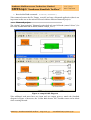
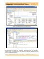
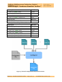
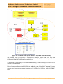
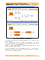
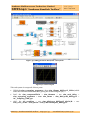
Sundance Multiprocessor Technology Limited SMT6040 “Sundance Simulink Toolbox” Form : QCF32 Date : 6 July 2006 Unit / Module Description: Sundance Simulink Toolbox for DSP-FPGA code generation Unit / Module Number: SMT6040 Document Issue Number: 3.1.0 Issue Date: 8th January 2009 Original Author: Simone Boragno SMT6040 “Sundance Simulink Toolbox” Abstract This document describes the SMT6040, a flexible tool for the co-design and co-generation of DSP and FPGA code from Simulink diagrams. The SMT6040 specifically targets Sundance boards and comes with a number of demos for different systems. The SMT6040 also allows the integration of Simulink designs with C code, VHDL code and System Generator diagrams, thus giving the maximum flexibility to the user. Sundance Italia SRL This document is the property of Sundance and may not be copied nor communicated to a third party without prior written permission. © Sundance Italia SRL 2009 SMT6040 - “Sundance Simulink Toolbox” Last Edited: 08/01/2010 15.42 Sundance Multiprocessor Technology Limited SMT6040 “Sundance Simulink Toolbox” Form : QCF32 Date : 6 July 2006 Revision History Issue Changes Made Date Initial s 1.0.0 Initial version 11/06/09 S.B. 1.0.1 Minor updates to demo descriptions 21/07/09 S.B. 1.0.2 Added pictures and further information on the demos 06/08/09 S.B. 2.0.0 Added information on the demos 21/08/09 S.B. 3.0.0 New Version 3.0 12/10/09 S.B. 3.0.1 Added description of SMT8036E and SMT8096 demo 18/11/09 S.B. 3.1.0 New SDR, RF, MIMO and WiMAX demos 08/01/10 S.B. SMT6040 - “Sundance Simulink Toolbox” Page 2 of 53 Last Edited: 08/01/2010 15.42 Sundance Multiprocessor Technology Limited SMT6040 “Sundance Simulink Toolbox” Form : QCF32 Date : 6 July 2006 Table of Contents 1 The SMT6040 Toolbox ................................................................................ 7 2 How to use the SMT6040............................................................................. 7 2.1 Integrate a SMT6040 Simulink DSP design into Diamond..........................................9 2.1.1 SMT6040 project .......................................................................................................9 2.1.2 Diamond project ......................................................................................................10 2.2 Integrate a Simulink FPGA design into Diamond....................................................... 12 2.2.1 Required signals....................................................................................................... 12 2.2.2 Channels................................................................................................................... 12 2.2.3 Driving pins.............................................................................................................. 14 2.2.4 Creating the task ...................................................................................................... 14 2.2.5 System Generator configuration ............................................................................. 14 2.2.6 Synthesizing the Task with XST Creating the task ................................................. 15 3 Main demo applications .............................................................................16 3.1 SDR and SDR + RF front-end demos .......................................................................... 16 3.1.1 4 SMT8036E SDR demo ........................................................................................... 20 3.2 Video demo .................................................................................................................. 20 3.3 DVIP demo....................................................................................................................23 3.4 WiMAX demo ...............................................................................................................26 3.5 MIMO_LTE demo ....................................................................................................... 30 3.6 RadioGiga demo ...........................................................................................................33 The SMT6040 package............................................................................... 36 4.1 Overview .......................................................................................................................36 4.2 SMT6040_DSP.............................................................................................................37 4.3 SMT6040_FPGA ..........................................................................................................37 4.4 SDR ...............................................................................................................................37 4.5 Video .............................................................................................................................39 4.6 DVIP ..............................................................................................................................39 4.7 MIMO_LTE ................................................................................................................. 40 4.8 WiMAX......................................................................................................................... 40 4.9 RadioGiga..................................................................................................................... 40 4.10 SMT6040_ generic...................................................................................................... 40 4.11 5 Miscellanea .................................................................................................................. 40 Version 2 ....................................................................................................41 5.1 Version 2 functionalities .............................................................................................. 41 SMT6040 - “Sundance Simulink Toolbox” Page 3 of 53 Last Edited: 08/01/2010 15.42 Sundance Multiprocessor Technology Limited SMT6040 “Sundance Simulink Toolbox” 6 Form : QCF32 Date : 6 July 2006 5.2 Simulate and run an application..................................................................................47 5.3 SDR demo – No Sysgen – Version 2........................................................................... 48 5.4 SDR demo SMT8036E – No Sysgen – Version 2....................................................... 50 5.5 Video demo – Version 2 ...............................................................................................52 Useful resources........................................................................................ 53 6.1 Links..............................................................................................................................53 6.2 Contacts.........................................................................................................................53 SMT6040 - “Sundance Simulink Toolbox” Page 4 of 53 Last Edited: 08/01/2010 15.42 Sundance Multiprocessor Technology Limited SMT6040 “Sundance Simulink Toolbox” Form : QCF32 Date : 6 July 2006 Table of Figures Figure 1: integration of Simulink diagrams in Diamond.............................................................8 Figure 2: sample DSP diagram ...................................................................................................10 Figure 3: Diamond project and connections...............................................................................11 Figure 4: data transfer .................................................................................................................11 Figure 5: channel configuration in System Generator............................................................... 13 Figure 6: System Generator configuration................................................................................. 15 Figure 7: netlist properties.......................................................................................................... 15 Figure 8 : SMT8246 SDR demo (FPGA tasks in red, DSP tasks in yellow) .............................. 17 Figure 9: SMT6040 diagram for SDR demo. ............................................................................. 18 Figure 10: Logical connections between DSP tasks (SDR demo).............................................. 18 Figure 11: output of the SDR demo 3.......................................................................................... 19 Figure 12: SMT8036E SDR demo (FPGA tasks in red, DSP tasks in blue) ............................. 20 Figure 13: Video demo (FPGA tasks in red, DSP tasks in yellow)............................................. 21 Figure 14: logical connections between DSP tasks (Video demo) .............................................22 Figure 15: Simulink diagram (Video demo) ...............................................................................22 Figure 16: basic Video processing example................................................................................23 Figure 17: DVIP demo (FPGA tasks in red, DSP tasks in yellow)..............................................24 Figure 18: logical connections between DSP tasks (DVIP demo) .............................................25 Figure 19: Simulink diagram (DVIP demo) ...............................................................................25 Figure 20: basic Video processing example on DVIP ................................................................26 Figure 21 : WiMAX demo (FPGA tasks in red, DSP tasks in yellow) ........................................27 Figure 22: SMT6040 diagram for WiMAX demo. .................................................................... 28 Figure 23: logical connections between DSP tasks (WiMAX demo).........................................29 Figure 24: output of the WiMAX demo......................................................................................29 Figure 25 : MIMO_LTE demo (FPGA tasks in red, DSP tasks in yellow) ............................... 30 Figure 26: SMT6040 diagram for MIMO_LTE demo............................................................... 31 Figure 27: logical connections between DSP tasks (MIMO_LTE demo)..................................32 Figure 28: output of the MIMO_LTE demo ..............................................................................32 Figure 29 : RadioGiga demo (FPGA tasks in red, DSP tasks in yellow)....................................33 Figure 30: SMT6040 diagram for RadioGiga demo..................................................................34 Figure 31: logical connections between DSP tasks (RadioGiga demo) .....................................35 Figure 32: output of the RadioGiga demo..................................................................................35 Figure 33: the SMT6040 Package ..............................................................................................37 Figure 34: a SMT6040 DSP-FPGA-ADC/DAC design............................................................... 41 SMT6040 - “Sundance Simulink Toolbox” Page 5 of 53 Last Edited: 08/01/2010 15.42 Sundance Multiprocessor Technology Limited SMT6040 “Sundance Simulink Toolbox” Form : QCF32 Date : 6 July 2006 Figure 35: root DSP sub-system .................................................................................................42 Figure 36: DSP hardware interface ............................................................................................43 Figure 37: Diamond channel hardware interface ......................................................................44 Figure 38: node1 DSP sub-system..............................................................................................44 Figure 39: SMT350 FPGA-ADC/DAC sub-system ...................................................................45 Figure 40: LEDs output ..............................................................................................................45 Figure 41: DAC configuration .....................................................................................................46 Figure 42: simulation results..................................................................................................... 48 Figure 43: SDR demo SMT6040 diagram..................................................................................49 Figure 44: SMT8036E demo ...................................................................................................... 51 Figure 45: Video demo 2 - DSP diagram....................................................................................52 SMT6040 - “Sundance Simulink Toolbox” Page 6 of 53 Last Edited: 08/01/2010 15.42 Sundance Multiprocessor Technology Limited SMT6040 “Sundance Simulink Toolbox” Form : QCF32 Date : 6 July 2006 1 The SMT6040 Toolbox The SMT6040 is a MATLAB toolbox that allows generating DSP and FPGA code for Sundance boards from a Simulink diagram. The users can describe their projects by means of a set of interconnected blocks, which are functionally identical to those from the Simulink library (math and logical operators, nonlinear and trigonometric functions, vector and matrix operations, modulators, etc.). The Sundance-provided blocks have a Data Flow calculation paradigm, just like Simulink blocks. The SMT6040 blocks accurately simulate their digital and analog counterparts; at the same time, the entire system is kept hardware-independent. Together with Sundance Legolike modular approach, the SMT6040 lets users port the same high-level Simulink project to many different Sundance systems quickly and easily. An advanced user can utilise the SMT6040 toolbox with all Sundance boards; however, a number of demos targeting the most common Sundance systems are provided to make the understanding and the use of the SMT6040 easier. These ready and working diagrams give customers a great starting point for their projects. The following chapter describes the SMT6040 functionalities. Chapter 3 provides an overview of the main demos (SDR, Video, DVIP, MIMO_LTE, WiMAX, RadioGiga). Chapter 4 describes the structure of the package and how to navigate its folders. Chapter 5 is dedicated only to the users of Version 2.1, which has now been replaced by the current Version 3.0. All demos and SMT6040 functionalities are accurately documented in the SMT6040 package. This manual aims to give an overview of the SMT6040, useful Getting Started instructions for the main demo applications, and a description of the main procedure to generate complex SMT6040 Simulink designs. 2 How to use the SMT6040 This chapter describes how to benefit of the SMT6040 to design DSP-FPGA applications from Simulink diagrams targeting Sundance hardware. For this purpose, the SMT6040 requires the following SW tools: • Matlab 7.5.0 and Simulink 7.0 • Real Time Workshop (version found in Matlab 7.5.0) • TI Code Composer Studio 3.3 • Xilinx ISE Foundation 10.1 • Xilinx System Generator 10.1 • Diamond 3.1.10 or Diamond 3.2 (DSP & FPGA licenses) The SMT6040 allows using 3L Diamond (the main development environment for Sundance hardware) as the integrator of Simulink diagrams targeting DSP-FPGA multi-processor systems. SMT6040 - “Sundance Simulink Toolbox” Page 7 of 53 Last Edited: 08/01/2010 15.42 Sundance Multiprocessor Technology Limited SMT6040 “Sundance Simulink Toolbox” Form : QCF32 Date : 6 July 2006 In fact, the SMT6040 takes advantage of Sundance modularity and scalability to generate multi-DSP/multi-FPGA applications from Simulink diagrams. The same application can target different systems by few changes in the configuration. Moreover, the SMT6040 uses Diamond channels to implement the communication between processors. So, the user just needs to set up these virtual channels. Each channel will be then mapped onto a comport or a SHB connection, thus fully exploiting Sundance communication resources. The SMT6040 will automatically configure the hardware and then manage the inter-processor communication. So the user does not need to worry about interrupts, data flow, etc. This makes development much easier and faster. To explain how SMT6040 and Diamond are combined to build a unique and powerful development environment, we remind that Diamond users can divide the application into different logical tasks and assign each task to the processor (DSP or FPGA) on which they would like the task to be executed. Figure 1: integration of Simulink diagrams in Diamond A DSP task can be implemented in C, but also generated from a Simulink Diagram thanks to the SMT6040. Similarly, a FPGA task can be implemented in VHDL, but also generated from a Simulink Diagram thanks to System Generator. SMT6040 - “Sundance Simulink Toolbox” Page 8 of 53 Last Edited: 08/01/2010 15.42 Sundance Multiprocessor Technology Limited SMT6040 “Sundance Simulink Toolbox” Form : QCF32 Date : 6 July 2006 This procedure is shown in Figure 1. Section 2.1 describes how to integrate a Simulink DSP task into Diamond. Section 2.2 describes how to integrate a Simulink FPGA task. 2.1 Integrate a SMT6040 Simulink DSP design into Diamond The SMT6040 allows generating full applications targeting Sundance HW, but it also supports Diamond DSP and it can be used to generate a DSP task. This is very useful as it adds flexibility and it makes it possible to integrate a Simulink design into a Diamond project and also into the Diamond demos provided by Sundance. Therefore, users can combine their Simulink algorithms with C/VHDL projects developed in Diamond (e.g. they can add their tasks – designed with the SMT6040 – to Diamond SDR or Video demos, which are provided by 3L). The design process for a combined SMT6040-Diamond application requires only the following simple steps: 1- Create a SMT6040 design that targets a DSP; 2- Compile the SMT6040 project; this will create the “T6040_root.tsk” DSP task; 3- Select the Diamond project of your interest and add the “T6040_root.tsk” task to it; 4- Connect the input/output ports of the “T6040_root.tsk” task and the ports of the Diamond task of your interest; 5- Set up the data transfer between the two tasks; 6- Build and run the demo in Diamond IDE. An example that explains this procedure is provided in the “SMT6040_generic” directory. This folder contains the Diamond project (based on the “fpga-example1” demo) and the Simulink project (represented in Figure 2). Please notice that this package targets the SMT362 DSP. If you need to target another board, you can select the correct module type by double-clicking on the “Digital HW Interface” block under the “DSP6040/root” sub-system. Please check that you are targeting the proper DSP module also in Diamond. 2.1.1 SMT6040 project The Simulink diagram is in this case performs three operations: - A sum of the two inputs is outputted on Diamond write Channel 0; - The second input is passed through to Diamond write Channel 1; - The sentence “SMT6040 task” is printed on the screen. To compile the “DSP6040.mdl” design, the following two steps are necessary: 1- Double click on “Digital HW Interface”, then click on “Compile To HW/SW Analog” and “Overall Build”; SMT6040 - “Sundance Simulink Toolbox” Page 9 of 53 Last Edited: 08/01/2010 15.42 Sundance Multiprocessor Technology Limited SMT6040 “Sundance Simulink Toolbox” Form : QCF32 Date : 6 July 2006 2- Run the MATLAB command: Diamond(‘DSP6040’) This command creates the file “T6040_root.tsk” and runs a Diamond application (that is not important in this case as the task will be used within a different Diamond project). 2.1.2 Diamond project The original “fpga-example1” Diamond project had only one DSP task (named “driver”). In this case, another DSP task is added (named “T6040_root”). Figure 2: sample DSP diagram This additional task must have two input and two output ports to match the Simulink diagram in Figure 2. Moreover, the “Create Main Source File” checkbox must not be ticked when creating the task. SMT6040 - “Sundance Simulink Toolbox” Page 10 of 53 Last Edited: 08/01/2010 15.42 Sundance Multiprocessor Technology Limited SMT6040 “Sundance Simulink Toolbox” Form : QCF32 Date : 6 July 2006 Figure 3: Diamond project and connections Figure 4: data transfer By right-clicking on “T6040_root”, clicking on “Add Existing Files”, and browsing to “T6040_root.tsk”, it is possible to add the .tsk file to the new task, which therefore will behave as the SMT6040 diagram. SMT6040 - “Sundance Simulink Toolbox” Page 11 of 53 Last Edited: 08/01/2010 15.42 Sundance Multiprocessor Technology Limited SMT6040 “Sundance Simulink Toolbox” Form : QCF32 Date : 6 July 2006 To let the “T6040_root” task communicate with the “driver” task, the “driver” task needs to have two additional output ports (named “to6040_0” and “to6040_1” respectively) and two additional input ports (named “from6040_0” and “from6040_1” respectively). Connections are created as in Figure 3. Finally, the data transfer between the two DSP tasks can be set up thanks to the functions “chan_out_message” and “chan_in_message” as in Figure 4. The printed output of the demo demonstrates the behaviour of the task created by the SMT6040 (the sum of the two inputs is calculated while the second input is passed through to the second output channel). This procedure can be applied to any Diamond demo. Of course, the SMT6040 DSP task can be modified in Simulink as for the users’ processing algorithms. 2.2 Integrate a Simulink FPGA design into Diamond System Generator is a popular design tool from Xilinx that allows designing Simulink diagrams targeting Xilinx FPGAs. As previously pointed out, it is possible to create a Diamond FPGA task from a System Generator project. Therefore, similarly to the DSP case described in the previous chapter, it is possible to modify a Diamond project or a Diamond demo (e.g. SDR or Video demos) by adding FPGA tasks generated from a Simulink diagram. This section describes how to use System Generator with Diamond to create and integrate a Diamond FPGA task. These instructions are extracted from Diamond User Guide. Please check it for more information: http://www.3l.com/user-guides/3l-diamond-for-sundance . 2.2.1 Required signals System Generator will automatically add the following ports for you if there is at least one synchronous element in the task. If your processing is purely asynchronous you can add a register on the validwords signal to force system generator to implement these ports. • clk • ce • rst Port ce_clr is not added by System Generator. You should add an input gateway to your model called 'ce_clr' to ensure this signal is present on the interface on the core created by System Generator. 2.2.2 Channels Unfortunately, System Generator supports only those types defined in the IEEE.STD package; in particular, it does not support record types. This means that you cannot use the convenient Diamond types described in Diamond User Guide; to create a channel you must implement all of the signals explicitly. The simplest approach is to name the signals in the same way as you would using record types, but replacing '.' with '_'. For example, the data bus would be ' x_chan_in_0_Data'. The ports are implemented using Gateway In and Gateway Out elements. Each input channel is specified as follows: SMT6040 - “Sundance Simulink Toolbox” Page 12 of 53 Last Edited: 08/01/2010 15.42 Sundance Multiprocessor Technology Limited SMT6040 “Sundance Simulink Toolbox” Gateway In Bus Size x_chan_in_index_data 64 bits x_chan_in_index_ready 1 bit x_chan_in_index_write 1 bit x_chan_in_index_validwords 2 bits Gateway Out Bus Size y_chan_in_index_ready 1 bit Form : QCF32 Date : 6 July 2006 Each output channel is specified as follows: Gateway In Bus Size y_chan_out_index_ready 1 bit Gateway Out Bus Size x_chan_out_index_data 64 bits x_chan_out_index_ready 1 bit x_chan_out_index_write 1 bit x_chan_out_index_validwords 2 bits Figure 5: channel configuration in System Generator SMT6040 - “Sundance Simulink Toolbox” Page 13 of 53 Last Edited: 08/01/2010 15.42 Sundance Multiprocessor Technology Limited SMT6040 “Sundance Simulink Toolbox” Form : QCF32 Date : 6 July 2006 index represents the channel number, the only variable part of the name. Both input and output are numbered from zero and the channel numbers must be continuous. You must still provide a package file that declares the task’s component; this declaration must use a record type — it is not looked at by System Generator. You shouldn’t specify any IOB Location Constraints when using System Generator. 2.2.3 Driving pins A System Generator task can connect to the pins of the FPGA. Gateways In and Out are used to implement the I/O buffers. The pin location, the electric standard and any other constraint must be specified in a UCF file accompanying the task. 2.2.4 Creating the task When you hit the "Generate" button System Generator compiles the Simulink model into a number of HDL files and netlists. These files should be added to the FCD file of your task along with the Diamond package file that you must create yourself. The following snippet shows an example of a System Generator task called 'addone_cw'. We have pre-synthesized the HDL files produced by System Generator to obtain the netlist 'addone_cw.ngc'. Note that we used the syntax '*.edn' to gather all the netlists produced by System Generator. PACKAGE "addone_cw_pkg.vhd" FILE "netlist\addone_cw.ngc" FILE "netlist\*.edn" 2.2.5 System Generator configuration System Generator is configured as in Figure 6 (this is an example, please change the configuration according to your HW). • Compilation must be set to 'HDL netlist'. • Part must be set to the FPGA type you are targeting. • Synthesis Tool must be set to XST. • Hardware Description Language must be set to VHDL. • FPGA Clock Period (ns) must be the frequency at which the task will be clocked. This setting is overwritten by Diamond with the frequency of the clock domain to which the task belongs. • Clock Pin Location must be left unspecified. Diamond connects the clock to the task according to the clock domain specified in the configuration file. SMT6040 - “Sundance Simulink Toolbox” Page 14 of 53 Last Edited: 08/01/2010 15.42 Sundance Multiprocessor Technology Limited SMT6040 “Sundance Simulink Toolbox” Form : QCF32 Date : 6 July 2006 Figure 6: System Generator configuration 2.2.6 Synthesizing the Task with XST Creating the task The VHDL files produced by System Generator may be synthesized with XST to produce a netlist. Figure 7: netlist properties The netlist generated must not have any I/O buffers, since the task will be used in a higher level design. In most cases it shouldn’t implement any clock buffers since Diamond will implement them for you. The configuration XST is shown in Figure 7. Add I/O buffers must not be ticked; all the other options can be set to values you choose. SMT6040 - “Sundance Simulink Toolbox” Page 15 of 53 Last Edited: 08/01/2010 15.42 Sundance Multiprocessor Technology Limited SMT6040 “Sundance Simulink Toolbox” Form : QCF32 Date : 6 July 2006 3 Main demo applications This chapter illustrates the main demos targeting some of Sundance most common systems. Please notice that these demos can easily be changed to target other systems. For a complete list of examples, please see Chapter 4. More detailed instructions can be found in the SMT6040 package. 3.1 SDR and SDR + RF front-end demos ! Demo: “..\Release_3.0\Applications\_Sundance\SDR\SDR_8146_8246_8096” ! Demo: “..\Release_3.0\Applications\_Sundance\SDR\SMT8036E_SDRDemo” (The demos targeting SMT8096, SMT8146 and SMT8246 are identical with the exception of the DSP type. The SMT8246 demo is described below, but these explanations apply also to the SMT8146, SMT8096 demos. A similar structure is the base of the SMR8036E. For this system the few differences with respect to the SMT8246 demo are explained in Paragraph 3.1.1). Same requirements apply as the ones described in Chapter 2. This is the recommended demo for Special University Offer SDR users. This demo targets the SMT8246 system but it can be easily changed to target other SDR systems. These demos have the structure described in Chapter 2. Therefore, they are made of Simulink projects implementing DSP/FPGA tasks and a Diamond IDE project that acts as integrator. In particular, in this same Diamond workspace different projects are available, in order to target different SDR systems: SMT8146 and SMT8246 (with SMT350 or SMT950, and with optional SMT349), SMT8096. Each project can be considered separately and the same Simulink diagram is valid for all the demos (only the DSP processor type should be changed to match the one of the system in use – i.e. SMT362, SM374 or SMT395). The diagram in Figure 8 represents a more detailed structure of the demo. The SDR_2 demo is composed by a number of DSP and FPGA tasks. The “main” function is in the DSP task named “smt350”. This task receives the data from the FPGA and sends the proper data to the display and FFT processing tasks. As described in Chapter 2, a Diamond DSP task (e.g. named “T6040_root.tsk”) can be created by the SMT6040. This task can be added to the SDR Diamond project as explained in Chapter 3. This new task can communicate, for example, with the “smt350” DSP task. For this purpose, two input and one output ports have to be added to the “smt350” task. SMT6040 - “Sundance Simulink Toolbox” Page 16 of 53 Last Edited: 08/01/2010 15.42 Sundance Multiprocessor Technology Limited SMT6040 “Sundance Simulink Toolbox” Form : QCF32 Date : 6 July 2006 Figure 8 : SMT8246 SDR demo (FPGA tasks in red, DSP tasks in yellow) SMT6040 - “Sundance Simulink Toolbox” Page 17 of 53 Last Edited: 08/01/2010 15.42 Sundance Multiprocessor Technology Limited SMT6040 “Sundance Simulink Toolbox” Form : QCF32 Date : 6 July 2006 Figure 9: SMT6040 diagram for SDR demo. These ports need to be connected to the input/output ports of the “T6040_root” task as shown in Figure 10. Figure 10: Logical connections between DSP tasks (SDR demo) SMT6040 - “Sundance Simulink Toolbox” Page 18 of 53 Last Edited: 08/01/2010 15.42 Sundance Multiprocessor Technology Limited SMT6040 “Sundance Simulink Toolbox” Form : QCF32 Date : 6 July 2006 In the “main” function in “smt350.c”, the functions “chan_out_message” and “chan_in_message” can be used respectively to send data to “T6040_root” and to receive the processed data from it. Displays and “printf” statements (in the “main” function) will allow simple verification of the behaviour of the “T6040_root” task designed in Simulink. The folder “SMT8246_SDRDemo” contains a Simulink example, which is used to generate a Diamond DSP task with two inputs and one output, and the Diamond SDR demo, to which the “T6040_root” DSP task is added. The SMT6040 task is dedicated to process the incoming data from the “main” task and to output (again to the “main” task) the processing results. The diagram generating the task is represented in Figure 9 and the processing results of the SDR Diamond demo (when calling the T6040_root task) are pictured in Figure 11. In this picture it appears clear that the “Time domain – Channel 1” output is equal to the sum of two signals identical to the one displayed as “Time domain – Channel 2”. Figure 11: output of the SDR demo 3 SMT6040 - “Sundance Simulink Toolbox” Page 19 of 53 Last Edited: 08/01/2010 15.42 Sundance Multiprocessor Technology Limited SMT6040 “Sundance Simulink Toolbox” 3.1.1 Form : QCF32 Date : 6 July 2006 SMT8036E SDR demo Demo: “..\Release_3.0\Applications\_Sundance\SDR\SMT8036E_SDRDemo” There are few differences between the SMT8246 SDR demo described in Section 3.1 and the SMT8036E demo. The structure of the SMT8036E demo is highlighted in . Figure 12: SMT8036E SDR demo (FPGA tasks in red, DSP tasks in blue) We recommend customers to check the Diamond project for further details. 3.2 Video demo ! Demo: “..\Release_3.0\Applications\_Sundance\Video\VideoDemo” This demo targets the Video kit and the VisionMax kit and requires the use of Diamond Video Library (DVL). One of the sample applications included in the DVL is integrated with the SMT6040 by following the procedures previously described. The resulting structure of the demo is represented in Figure 13. SMT6040 - “Sundance Simulink Toolbox” Page 20 of 53 Last Edited: 08/01/2010 15.42 Sundance Multiprocessor Technology Limited SMT6040 “Sundance Simulink Toolbox” Form : QCF32 Date : 6 July 2006 Figure 13: Video demo (FPGA tasks in red, DSP tasks in yellow) In particular, this basic demo performs some DSP operations on two lines of the image to show how it is possible to use the SMT6040 to process the video acquired by a camera. The DVL deals with data acquisition. Once a video frame has been captured, two lines of the image are passed to a Simulink task, as outlined in Figure 14. SMT6040 - “Sundance Simulink Toolbox” Page 21 of 53 Last Edited: 08/01/2010 15.42 Sundance Multiprocessor Technology Limited SMT6040 “Sundance Simulink Toolbox” Form : QCF32 Date : 6 July 2006 Figure 14: logical connections between DSP tasks (Video demo) Figure 15: Simulink diagram (Video demo) SMT6040 - “Sundance Simulink Toolbox” Page 22 of 53 Last Edited: 08/01/2010 15.42 Sundance Multiprocessor Technology Limited SMT6040 “Sundance Simulink Toolbox” Form : QCF32 Date : 6 July 2006 The whole Simulink diagram (top view and detail of the root subsystem) is pictured in Figure 15. It is easy to understand the two simple processing steps applied by the SMT6040 task. The result of the element-by-element subtraction of the input vectors is sent to output 1. Output 2 is a simple passthrough of input 2. However, the second output of the Simulink task becomes the first input of the Diamond “demo_pal” DSP task. So the processing has two results: the second line of the image is copied in place of the first line, while the result of the subtraction replaces the second line passed to the Simulink task. This process is executed on each of the three frames loaded by the DVL. This is better explained by Figure 16, which shows on the left the original image, and on the right the results of its binarization to black&white and of the processing on the two lines (in particular, a white line replaces a line in the top half of the image, while a dark line is drawn in the bottom half of the video). Figure 16: basic Video processing example By using a similar procedure, it is possible to add a DSP task created in Simulink to any of the DVL demos. More complex application can easily be designed thanks to the integration of SMT6040 and Diamond. The folder “VideoDemo” includes the Simulink project (represented in Figure 15) that has been used to generate a DSP task named “T6040_root.tsk”. The “VideoDemo” folder contains the DVL workspace where this task has been inserted into Diamond Video Demo “demo2”. 3.3 DVIP demo ! Demo: “..\Release_3.0\Applications\_Sundance\DVIP\DVIPDemo” This demo requires the use of Diamond Video Library (DVL). One of the sample applications included in the DVL is integrated with the SMT6040 by following the procedures previously described. The resulting structure of the demo is represented in Figure 17. In particular, this basic demo performs some DSP operations on two lines of the image to show how it is possible to use the SMT6040 to process the video acquired by a camera. SMT6040 - “Sundance Simulink Toolbox” Page 23 of 53 Last Edited: 08/01/2010 15.42 Sundance Multiprocessor Technology Limited SMT6040 “Sundance Simulink Toolbox” Form : QCF32 Date : 6 July 2006 The DVL deals with data acquisition. Once a video frame has been captured, two lines of the image are passed to a Simulink task, as outlined in Figure 18. Figure 17: DVIP demo (FPGA tasks in red, DSP tasks in yellow) The whole Simulink diagram (top view and detail of the root subsystem) is pictured in Figure 19. SMT6040 - “Sundance Simulink Toolbox” Page 24 of 53 Last Edited: 08/01/2010 15.42 Sundance Multiprocessor Technology Limited SMT6040 “Sundance Simulink Toolbox” Form : QCF32 Date : 6 July 2006 Figure 18: logical connections between DSP tasks (DVIP demo) Figure 19: Simulink diagram (DVIP demo) SMT6040 - “Sundance Simulink Toolbox” Page 25 of 53 Last Edited: 08/01/2010 15.42 Sundance Multiprocessor Technology Limited SMT6040 “Sundance Simulink Toolbox” Form : QCF32 Date : 6 July 2006 It is easy to understand the two simple processing steps applied by the SMT6040 task. The result of the element-by-element subtraction of the input vectors is sent to output 1. Output 2 is a simple passthrough of input 2. However, the second output of the Simulink task becomes the first input of the Diamond “demo_pal” DSP task. So the processing has two results: the second line of the image is copied in place of the first line, while the result of the subtraction replaces the second line passed to the Simulink task. This process is executed on each of the three frames loaded by the DVL. This is better explained by Figure 20, which shows on the left the original image, and on the right the results of its binarization to black&white and of the processing on the two lines (in particular, a white line replace a line in the top half of the image, while a dark line is drawn in the bottom half of the video). Figure 20: basic Video processing example on DVIP By using a similar procedure, it is possible to add a DSP task created in Simulink to any of the DVL demos. More complex applications (also targeting multi-DSPs) can easily be designed thanks to the integration of SMT6040 and Diamond. The folder “DVIPDemo” includes the Simulink project (represented in Figure 19) that has been used to generate a DSP task named “T6040_root.tsk”. The “DVIPDemo” folder contains the DVL workspace project where this task has been inserted into Diamond DVIP Demo. 3.4 WiMAX demo ! Demo: “..\Release_3.0\Applications\_Sundance\WiMAX\WiMAXDemo” Same requirements as described in Chapter 2. This is the recommended demo for Special University Offer WiMAX users. SMT6040 - “Sundance Simulink Toolbox” Page 26 of 53 Last Edited: 08/01/2010 15.42 Sundance Multiprocessor Technology Limited SMT6040 “Sundance Simulink Toolbox” Form : QCF32 Date : 6 July 2006 The diagram represented in Figure 21 pictures the structure of the demo. Figure 21 : WiMAX demo (FPGA tasks in red, DSP tasks in yellow) The WiMAX demo is composed by a number of DSP and FPGA tasks. The DSP task “SMT903_DSP_CONTROL. sends control information to the FPGA and receives/sends data to the FPGA task that deals with RF transmission. As described in paragraph 3.1.1, a Diamond DSP task (e.g. named “T6040_root.tsk”) can be created by the SMT6040. This task can be added to the WiMAX Diamond project as explained in Chapter 3. This new task can communicate, for example, with the “SMT903_DSP_CONTROL” DSP task. For this purpose, two input and one output ports have to be added to the “SMT903_DSP_CONTROL” task. SMT6040 - “Sundance Simulink Toolbox” Page 27 of 53 Last Edited: 08/01/2010 15.42 Sundance Multiprocessor Technology Limited SMT6040 “Sundance Simulink Toolbox” Form : QCF32 Date : 6 July 2006 Figure 22: SMT6040 diagram for WiMAX demo. These ports need to be connected to the input/output ports of the “T6040_root” task as shown in Figure 23. In the “update_thread” function in “SMT903_DSP_CONTROL.c”, the functions “chan_out_message” and “chan_in_message” can be used respectively to send data to “T6040_root” and to receive the processed data from it. Displays and “printf” statements will allow simple verification of the behaviour of the “T6040_root” task designed in Simulink. The folder “WiMAXDemo” contains a Simulink example, which is used to generate a Diamond DSP task with two inputs and one output, and the Diamond WiMAX demo, to which the “T6040_root” DSP task is added. SMT6040 - “Sundance Simulink Toolbox” Page 28 of 53 Last Edited: 08/01/2010 15.42 Sundance Multiprocessor Technology Limited SMT6040 “Sundance Simulink Toolbox” Form : QCF32 Date : 6 July 2006 Figure 23: logical connections between DSP tasks (WiMAX demo) Figure 24: output of the WiMAX demo The SMT6040 task is dedicated to process the incoming data from the “main” task and to output (again to the “main” task) the processing results. The diagram generating the task is represented in Figure 22 and the processing results of the WiMAX Diamond demo (when calling the T6040_root task) are pictured in Figure 24. In this picture it appears clear that SMT6040 - “Sundance Simulink Toolbox” Page 29 of 53 Last Edited: 08/01/2010 15.42 Sundance Multiprocessor Technology Limited SMT6040 “Sundance Simulink Toolbox” Form : QCF32 Date : 6 July 2006 the “Time domain – Channel 1” output is equal to the sum of two signals identical to the one displayed as “Time domain – Channel 2”. 3.5 MIMO_LTE demo ! Demo: “..\Release_3.0\Applications\_Sundance\MIMO_LTE\ MIMODemo” Same requirements as described in Chapter 2. This is the recommended demo for Special University Offer MIMO_LTE users The diagram in Figure 25 represents the structure of the MIMO_LTE demo. Figure 25 : MIMO_LTE demo (FPGA tasks in red, DSP tasks in yellow) The MIMO_LTE demo is composed by two projects (one for TX and one for RX), each made of a number of DSP and FPGA tasks. The “main” function is in the DSP task named SMT6040 - “Sundance Simulink Toolbox” Page 30 of 53 Last Edited: 08/01/2010 15.42 Sundance Multiprocessor Technology Limited SMT6040 “Sundance Simulink Toolbox” Form : QCF32 Date : 6 July 2006 “Dual_TX” (of the “TX” project). This task sends/receives control information and data to/from the FPGA. As described in paragraph 3.1.1, a Diamond DSP task (e.g. named “T6040_root.tsk”) can be created by the SMT6040. This task can be added to the MIMO_LTE Diamond project as explained in Chapter 3. This new task can communicate, for example, with the “Dual_TX” DSP task. For this purpose, two input and one output ports have to be added to the “Dual _TX” task. Figure 26: SMT6040 diagram for MIMO_LTE demo. These ports need to be connected to the input/output ports of the “T6040_root” task as shown in Figure 27. In the “main” function in “Dual_TX.c”, the functions “chan_out_message” and “chan_in_message” can be used respectively to send data to “T6040_root” and to receive the processed data from it. This is done during normal operation when the user selects option number 6 of the MIMO_LTE menu. Displays and “printf” statements (in the “main” function) will allow simple verification of the behaviour of the “T6040_root” task designed in Simulink. SMT6040 - “Sundance Simulink Toolbox” Page 31 of 53 Last Edited: 08/01/2010 15.42 Sundance Multiprocessor Technology Limited SMT6040 “Sundance Simulink Toolbox” Form : QCF32 Date : 6 July 2006 Figure 27: logical connections between DSP tasks (MIMO_LTE demo) Figure 28: output of the MIMO_LTE demo The folder “MIMODemo” contains a Simulink example, which is used to generate a Diamond DSP task with two inputs and one output, and the Diamond SDR demo, to which the “T6040_root” DSP task is added. SMT6040 - “Sundance Simulink Toolbox” Page 32 of 53 Last Edited: 08/01/2010 15.42 Sundance Multiprocessor Technology Limited SMT6040 “Sundance Simulink Toolbox” Form : QCF32 Date : 6 July 2006 The SMT6040 task is dedicated to process the incoming data from the “main” task and to output (again to the “main” task) the processing results. The diagram generating the task is represented in Figure 26 and the processing results of the MIMO Diamond demo (when calling the T6040_root task) are pictured in Figure 28. In this picture it appears clear that the “Time domain – Channel 1” output is equal to the sum of two signals identical to the one displayed as “Time domain – Channel 2”. 3.6 RadioGiga demo ! Demo: “..\Release_3.0\Applications\_Sundance\RadioGiga\RadioGigaDemo” Same requirements as described in Chapter 2. This is the recommended demo for Special University Offer RadioGiga users. Figure 29 : RadioGiga demo (FPGA tasks in red, DSP tasks in yellow) The diagram represented in Figure 29 pictures the structure of the demo. SMT6040 - “Sundance Simulink Toolbox” Page 33 of 53 Last Edited: 08/01/2010 15.42 Sundance Multiprocessor Technology Limited SMT6040 “Sundance Simulink Toolbox” Form : QCF32 Date : 6 July 2006 The RadioGiga demo is composed by a number of DSP and FPGA tasks. The “main” function is in the DSP task named “root”. This task receives the data from the FPGA and sends the proper data to the display tasks. As described in paragraph 3.1.1, a Diamond DSP task (e.g. named “T6040_root.tsk”) can be created by the SMT6040. This task can be added to the SDR Diamond project as explained in Chapter 3. This new task can communicate, for example, with the “root” DSP task. For this purpose, two input and one output ports have to be added to the “root” task. Figure 30: SMT6040 diagram for RadioGiga demo. These ports need to be connected to the input/output ports of the “T6040_root” task as shown in Figure 31. SMT6040 - “Sundance Simulink Toolbox” Page 34 of 53 Last Edited: 08/01/2010 15.42 Sundance Multiprocessor Technology Limited SMT6040 “Sundance Simulink Toolbox” Form : QCF32 Date : 6 July 2006 Figure 31: logical connections between DSP tasks (RadioGiga demo) Figure 32: output of the RadioGiga demo SMT6040 - “Sundance Simulink Toolbox” Page 35 of 53 Last Edited: 08/01/2010 15.42 Sundance Multiprocessor Technology Limited SMT6040 “Sundance Simulink Toolbox” Form : QCF32 Date : 6 July 2006 In the “main” function in “root.c”, the functions “chan_out_message” and “chan_in_message” can be used respectively to send data to “T6040_root” and to receive the processed data from it. Displays and “printf” statements (in the “main” function) will allow simple verification of the behaviour of the “T6040_root” task designed in Simulink. The folder “RadioGigaDemo” contains a Simulink example, which is used to generate a Diamond DSP task with two inputs and one output, and the Diamond RadioGiga demo, to which the “T6040_root” DSP task is added. The SMT6040 task is dedicated to process the incoming data from the “main” task and to output (again to the “main” task) the processing results. The diagram generating the task is represented in Figure 30 and the processing results of the RadioGiga Diamond demo (when calling the T6040_root task) are pictured in Figure 32. In this picture it appears clear that the “Time domain – Channel 1” output is equal to the sum of two signals identical to the one displayed as “Time domain – Channel 2”. 4 The SMT6040 package 4.1 Overview The SMT6040 is provided with instructions that guide the user through the software installation. Once the toolbox is correctly installed, two directories will be loaded in MATLAB: “_Sundance” and “Miscellaneous_demos”. In “Miscellaneous_demos” there are many general purpose Simulink diagrams that do not specifically target the latest Sundance hardware, but they could be used as examples for custom designs. However, we invite customers to focus on the folder “_Sundance”, which is specifically dedicated to Sundance systems and provides many working applications, useful demos and examples, accurate instructions. By double-clicking on “_Sundance”, a number of folders (each containing a group of demos targeting Sundance boards) will be visualized, as in Figure 33. The following paragraphs list all the demos. The main demo applications for Sundance SDR, Video, DVIP, MIMO, WiMAX, RadioGiga systems are more accurately described in Chapter 4. These examples are very useful as starting points. They can then be changed by the user both to implement new algorithms and to target different systems. SMT6040 - “Sundance Simulink Toolbox” Page 36 of 53 Last Edited: 08/01/2010 15.42 Sundance Multiprocessor Technology Limited SMT6040 “Sundance Simulink Toolbox” Form : QCF32 Date : 6 July 2006 Figure 33: the SMT6040 Package 4.2 SMT6040_DSP These demos demonstrate the behaviour of multi-DSP application targeting DSP boards like SMT362, SMT395Q, SMT363, SMT374, SMT365, SMT365E, SMT395VP30. 4.3 SMT6040_FPGA This folder contains a number of generic demos that can be used as examples for FPGA programming via Simulink (these examples are not supported anymore). 4.4 SDR Several demos are divided in a number of sub-folders: SDR_8146_8246_8096: it includes a “SimulinkProject” that creates a DSP task from a SMT6040 diagram and a Diamond workspace (“SDR”) that uses this task. More details in this regard in Chapters 3 and 4. The Diamond workspace includes different projects targeting the following possible systems: - SMT8246 (SMT350 version) - SMT8246 (SMT950 version) - SMT8146 (SMT350 version) - SMT8146 (SMT950 version) - SMT8246 (SMT350 version) + SMT349 - SMT8246 (SMT950 version) + SMT349 - SMT8146 (SMT350 version) + SMT349 - SMT8146 (SMT950 version) + SMT349 - SMT8096 These demos are recommended as starting points for customers’ developments on these systems. SMT6040 - “Sundance Simulink Toolbox” Page 37 of 53 Last Edited: 08/01/2010 15.42 Sundance Multiprocessor Technology Limited SMT6040 “Sundance Simulink Toolbox” Form : QCF32 Date : 6 July 2006 SMT8036E_SDRDemo: it includes a “SimulinkProject” that creates a DSP task from a SMT6040 diagram and a Diamond project that uses this task. More details in this regard in Chapters 3 and 4. This demo is recommended as starting point for all users of the SMT8036E SDR Special University Offer. Version2\SMT8096_noSysGen: this folder includes obsolete demos targeting systems composed by SMT395 or SMT362 as DSP board and by SMT368 or SMT351T as FPGA board, plus the SMT350 as DAQ module. These demos are not supported but they can be utilized by advanced users for their custom developments. These demos fully demonstrate the functionality of the hardware: processing on the DSP and data acquisition from ADC/DAC board through the FPGA. These demos target a number of Sundance SDR systems as highlighted in the table below. For more accurate descriptions, please read Chapter 4. Please notice that these demos are designed for a PCI carrier (SMT310Q). Users of standalone carriers (e.g. SMT148-FX) can easily modify these demos (in particular comport connections) to adapt them to their needs. Demo System SMT8096_ADC_DSP_DAC.mdl SMT8096 (SMT395+SMT368+SMT350) SMT8096_DSP_only.mdl SMT8096 (SMT395+SMT368+SMT350) test_SMT368_SMT362.mdl SMT362+SMT368+SMT350 test_SMT351TSX95_SMT395VP30.mdl SMT395+SMT351TSX95+SMT350 test_SMT351TSX50_SMT395VP30.mdl SMT395+SMT351TSX50+SMT350 test_SMT351TSX95_SMT362.mdl SMT362+SMT351TSX95+SMT350 test_SMT351TSX50_SMT362.mdl SMT362+SMT351TSX50+SMT350 test_SMT395: this folder contains a test demo for the SMT395 DSP. Version2_OLD\test_SMT368: this folder contains a demo that tests the SMT368 leds (“testLeds.mdl”) and a demo that can be used as an example design for the SMT368+SMT350 combination. test_SMT362: these demos demonstrate the behaviour of the SMT362 DSP board when using only one or both DSPs. Version2_OLD\test_SMT351T: here are a demo to test the SMT351T alone (“testLeds.mdl”) and two demos to be used as examples for the SMT351T+SMT350 combination. Version2_OLD\test_SMT350: this folder contains a number of designs that target the SMT350 board (they should be utilised by advanced users). Version2_OLD\SDR_SMT8036E: This folder is divided in a number of subfolders, each containing demos targeting the whole system or the single boards that compose the SDR_SMT8036E kit (SMT365E and SMT370. The SMT365 was featured in the SMT8036 and has now been replaced by the SMT365E, so its demos are not relevant for new users). SMT6040 - “Sundance Simulink Toolbox” Page 38 of 53 Last Edited: 08/01/2010 15.42 Sundance Multiprocessor Technology Limited SMT6040 “Sundance Simulink Toolbox” Form : QCF32 Date : 6 July 2006 Version2_OLD\SDR_SMT8036E\test_SMT8036: this folder contains a number of demos that target both the SMT8036 and SMT8036E systems. All SMT8036E users should use the “ADC_DSP_DAC.mdl” as a reference demo for this system and as a starting point for their projects. Version2_OLD\SDR_SMT8036E\test_SMT370: this folder contains demos that test the leds and the DAQ functionalities of the SMT370 board. Version2_OLD\SDR_SMT8036E\test_SMT365E: this folder contains a demo testing the leds of the SMT365E board. The other demos should only be used as examples for custom designs. Version2_OLD\SDR_SMT8036E\test_SMT365: this folder contains a demo testing the leds of the SMT365 board. The other demos should only be used as examples for custom designs. Version2_OLD\SDR_SMT8036E\SignalGenerator: this folder contains a useful demo to test the SMT370 module. Please follow the instructions provided with the SMT6040. The other folders in Version2_OLD \SDR_SMT8036E (DownConversion, FMtransmitter, FrequencyModulation) include examples that advanced users can take as reference diagrams for their designs. 4.5 Video To design complete applications (including Video I/O) targeting Sundance Video kit and Sundance VisionMax kit, the SMT6040 has to be used together with Diamond Video Library. VideoDemo: it includes a “SimulinkProject” that creates a DSP task from a SMT6040 diagram and a Diamond project (“VideoDemo”) that uses this task. More details in this regard in Chapters 3 and 4. It should be considered as the main Getting Started demo for the Video kit. Version2\test_SMT8039: it contains an example targeting the SMT8039 system. It illustrates how to create a DSP application using the SMT6040 and a default FPGA firmware (without Diamond). It is a simple example and is not optimised, so performance is low. 4.6 DVIP To design complete applications (including Video I/O) targeting Sundance DVIP kit, the SMT6040 has to be used together with Diamond Video Library. DVIPDemo: It includes a “SimulinkProject” that creates a DSP task from a SMT6040 diagram and a Diamond project that uses this task. More details in this regard in Chapters 3 and 4. It should be considered as the main Getting Started demo for the DVIP. Version2\test_SMT8039: it contains an example targeting the SMT8039 system. It illustrates how to create a DSP application using the SMT6040 and a default FPGA firmware (without Diamond). It is a simple example and is not optimised, so performance is low. test_SMT362: this demo demonstrates the behaviour of the SMT362 DSP board when using only one or both DSPs. SMT6040 - “Sundance Simulink Toolbox” Page 39 of 53 Last Edited: 08/01/2010 15.42 Sundance Multiprocessor Technology Limited SMT6040 “Sundance Simulink Toolbox” Form : QCF32 Date : 6 July 2006 4.7 MIMO_LTE MIMODemo: It includes a “SimulinkProject” that creates a DSP task from a SMT6040 diagram and a Diamond project that uses this task. More details in this regard in Chapters 3 and 4. test_SMT362: this demo demonstrates the behaviour of the SMT362 DSP board when using only one or both DSPs. Version2\test_SMT351T: here are a demo to test the SMT351T alone (“testLeds.mdl”) and two demos to be used as examples for the SMT351T+SMT350 combination. 4.8 WiMAX WiMAXDemo: It includes a “SimulinkProject” that creates a DSP task from a SMT6040 diagram and a Diamond project that uses this task. More details in this regard in Chapters 3 and 4. test_SMT362: this demo demonstrates the behaviour of the SMT362 DSP board when using only one or both DSPs. Version2\test_SMT351T: here are a demo to test the SMT351T alone (“testLeds.mdl”) and two demos to be used as examples for the SMT351T+SMT350 combination. 4.9 RadioGiga RadioGigaDemo: It includes a “SimulinkProject” that creates a DSP task from a SMT6040 diagram and a Diamond project that uses this task. More details in this regard in Chapters 3 and 4. test_SMT362: this demo demonstrates the behaviour of the SMT362 DSP board when using only one or both DSPs. Version2\test_SMT351T: here are a demo to test the SMT351T alone (“testLeds.mdl”) and two demos to be used as examples for the SMT351T+SMT350 combination. 4.10 SMT6040_ generic This folder contains a simple example for the development procedure described in Chapter 2. One folder (“SimulinkProject”) contains the SMT6040 diagram used to create a DSP task. The other folder features a simple DSP-FPGA Diamond example using this DSP task. 4.11 Miscellanea In the “generic” folder there are some demos for data transfer (in particular via comport or SHB). Boards targeted are SMT370 and SMT368. These demos should be used as examples and as general reference for custom designs. They are not meant to demonstrate full functionality of Sundance systems. The “obsolete” folder contains a number of obsolete demos that could be taken as examples for custom designs. However, their use is not supported and we suggest focusing on the other demos. SMT6040 - “Sundance Simulink Toolbox” Page 40 of 53 Last Edited: 08/01/2010 15.42 Sundance Multiprocessor Technology Limited SMT6040 “Sundance Simulink Toolbox” Form : QCF32 Date : 6 July 2006 5 Version 2 5.1 Version 2 functionalities This section describes the main functionalities of the Version 2, from the basic operations to the most advanced features. We recommend new customers (using Version 3.0) to follow the instructions in the previous chapters. The main demos included in Version 2 are described from paragraph 5.3 onwards. The SMT6040 takes advantage of Sundance modularity and scalability to generate multiDSP/multi-FPGA applications from Simulink diagrams. The same application can target different systems by few changes in the configuration. Moreover, the SMT6040 uses Diamond channels to implement the communication between processors. So, the user just needs to set up these virtual channels. Each channel will be then mapped onto a comport or a SHB connection, thus fully exploiting Sundance communication resources. The SMT6040 will automatically configure the hardware and then manage the inter-processor communication. So the user does not need to worry about interrupts, data flow, etc. This makes development much easier and faster. We use now a sample application to demonstrate the SMT6040 features and to describe how to generate an application targeting a DSP-FPGA-ADC/DAC system. We consider the system diagram represented in Figure 34. This is composed by three main blocks (each related to a processor) and a number of other blocks that we will now outline. A similar structure can be used for many different systems and applications. Figure 34: a SMT6040 DSP-FPGA-ADC/DAC design SMT6040 - “Sundance Simulink Toolbox” Page 41 of 53 Last Edited: 08/01/2010 15.42 Sundance Multiprocessor Technology Limited SMT6040 “Sundance Simulink Toolbox” Form : QCF32 Date : 6 July 2006 Figure 35: root DSP sub-system The sim_digHwInterface block represents the Sundance carrier board (generally a SMT310Q, but, thanks to Sundance modularity, this same demo can be run on a SMT148-FX carrier without changing any SMT6040 parameters – only the wires will need to be redefined in case different hardware links are in place). Each processor is associated with a sim_system block, whose name will automatically be given to the corresponding Diamond nodes or FPGA configuration file. It is important that one of the DSPs on the board located on TIM1 of the carrier is given the name root. All the others may have any valid name (alphanumeric characters, no blank). Inside each DSP (that is, inside each sim_system) there is a SMT6040 model of the algorithm that shall be placed onto that DSP. For instance, in node root (double-click on block root) there is the sub-system pictured in Figure 35. This shows how to use Diamond channels and how to process the data received by another processor. Where the sim_digHwInterface block represents one of the two DSPs of the SMT362 board, so it is configured as in Figure 36. Please notice that the scrolldown menu allows selecting the target board among several Sundance boards, so users can configure the application to target their hardware. SMT6040 - “Sundance Simulink Toolbox” Page 42 of 53 Last Edited: 08/01/2010 15.42 Sundance Multiprocessor Technology Limited SMT6040 “Sundance Simulink Toolbox” Form : QCF32 Date : 6 July 2006 Figure 36: DSP hardware interface Other blocks generate two sequences of data: • A Ramp on Diamond output channel 0 (write), which goes to node node1, as described in the top diagram. • A Sine on Diamond output channel 1 (write), which goes to node node1, as described in the top diagram. The remaining blocks receive data from: • Diamond input channel 0 (read), which comes from the FPGA module, as described in the top diagram; data is a 2-dimensional vector formatted as shown in the Input Digital HW Parameters dialog box of the sim_Diamond_channel block. Configuration can be changed as shown in Figure 37. • Diamond input channel 1 (read), which comes from node node1, as described in the top diagram, process them and occasionally printf to the console. SMT6040 - “Sundance Simulink Toolbox” Page 43 of 53 Last Edited: 08/01/2010 15.42 Sundance Multiprocessor Technology Limited SMT6040 “Sundance Simulink Toolbox” Form : QCF32 Date : 6 July 2006 Figure 37: Diamond channel hardware interface The second node (node1) is shown in Figure 38. Figure 38: node1 DSP sub-system It receives two sequences of data, from Diamond channel 0 (read) and Diamond channel 1 (read), respectively, which receive data from node root, as shown in the top diagram. These are summed up together and the result is: • Printed (sim_printf) to the console; • Sent to the Diamond channel 0 (write), which is connected to the node root, as shown in the top diagram; • Muxed into a 2-elements vector and sent, via Diamond channel 1 (write) to the FPGA module, as shown in the top diagram. The sim_digHwInterface is exactly as in node root, as this is the second DSP of the same SMT362 board. The third node SMT350 implements the Simulink diagram that programs the FPGA + ADC/DAC combination (in this example, SMT351T + SMT350 board). The SMT350 diagram is shown in Figure 39. This demonstrates how the SMT6040 can be used to program FPGA modules and also to configure the SMT350 DAQ board. SMT6040 - “Sundance Simulink Toolbox” Page 44 of 53 Last Edited: 08/01/2010 15.42 Sundance Multiprocessor Technology Limited SMT6040 “Sundance Simulink Toolbox” Form : QCF32 Date : 6 July 2006 Figure 39: SMT350 FPGA-ADC/DAC sub-system Figure 40: LEDs output This sub-system is composed of three parts: • LEDS: the sim_repeating_sequence + three sim_digout_SMT351T_LEDx (which make the LEDS the FPGA blink thus getting the results in Figure 40). • DAC: the sim_comport2FPGA + sim_demux2 + two sim_unit_delay + sim_repeating_sequence + two sim_sum2 + sim_DAC5686_SMT351T + AC_coupling_SMT350. • ADC: the AC_coupling + two sim_ADS5500_SMT351T_ADCA/B + two sim_zero_order + sim_mux2 + sim_FPGA2comport_SMT351T. SMT6040 - “Sundance Simulink Toolbox” Page 45 of 53 Last Edited: 08/01/2010 15.42 Sundance Multiprocessor Technology Limited SMT6040 “Sundance Simulink Toolbox” Form : QCF32 Date : 6 July 2006 Figure 41: DAC configuration The DAC part does the following: o It takes data coming from node1 via comport. o Demux data into two individual scalar channels. o Oversample both signals at 61,440,000 samples/s, as required by the DAC. o Generate a 61,440,000/8 Hz = 7.68 MHz sinewave. o Sum input signals to the sinewave. o Send both signals to the DAC, which is configured as in Figure 41, to operate as a normal two independent channels DAC. o Output signals via the AC coupling to the coax connectors. During simulation, the analog outputs are visible on the dual-channel scope present in the root model. The ADC part does the following: SMT6040 - “Sundance Simulink Toolbox” Page 46 of 53 Last Edited: 08/01/2010 15.42 Sundance Multiprocessor Technology Limited SMT6040 “Sundance Simulink Toolbox” Form : QCF32 Date : 6 July 2006 o Sample the two input analog channels at 61,440,000 samples/s (double-click on the ADCs to see sample frequency and other parameters). During simulations, data come from two signal generators present in the root model. o Sub-sample both channels with period STime (a variable from the MATLAB workspace set by the sim_setParam block in the root model. o Mux them together into a 2-dimensional vector (sim_mux2). o Send the vector to the root via a comport (sim_FPGA2comport block). 5.2 Simulate and run an application The SMT6040 application can be first verified during Simulation. Data printed on the screen and the graphs displayed by the scopes (Figure 42) can be used both for debugging and to verify the algorithm results. Compilation is very simple: users need to double-click on the sim_digHwInterface in the top diagram, then click on COMPILE TO HW/SW/ANALOG. Clicking on OVERALL BUILD shall trigger compilation, which will, in the sequence: • Split the whole system into subsystems (one for each sim_system). • Split each subsystem into a digital HW, a SW and an analog HW part (if any). • Compile each part independently. To build and execute the application on the hardware, a “.wir” file is necessary to define the hardware connections implemented (as users might connect different comports or SHBs). The following is an example of “.wir” file: wire ? root[CP:0] node1[CP:3] ! Internal connection between the two processors of SMT362 wire ? root[CP:1] node1[CP:4] ! Internal connection between the two processors of SMT362 ! The following assume a physical comport cable from ! T1C2 (TIM1) to T1C5 (TIM2) wire ? node1[CP:2] root[CP:5] ! Requires connection between [T1C2] to [T1C5] connect ? T6040_node1[1] node1[CP:1] ! Requires connection between [T1C1] to [T2C4] connect ? root[CP:4] T6040_root[0] ! Requires connection between [T1C4] to [T2C1] The instruction: Diamond(modelname) Builds the application (composed by DSP program and FPGA bitstream), download it onto the hardware and runs it. Results can be verified from the data printed on the screen and by connecting the DAC output to an oscilloscope. SMT6040 - “Sundance Simulink Toolbox” Page 47 of 53 Last Edited: 08/01/2010 15.42 Sundance Multiprocessor Technology Limited SMT6040 “Sundance Simulink Toolbox” Form : QCF32 Date : 6 July 2006 Figure 42: simulation results 5.3 SDR demo – No Sysgen – Version 2 ! Demo: “..\Release_3.0\Applications\_Sundance\SDR\Version2\SMT8096_noSysGen” For these demos, the SMT6040 requires the following SW tools: • Matlab 7.5.0 and Simulink 7.0 • Real Time Workshop (version found in Matlab 7.5.0) • TI Code Composer Studio 3.3 • Xilinx ISE Foundation 10.1 • Diamond 3.1.10 (DSP license) This section generally illustrates the following demos: Demo System test_SMT368_SMT362.mdl SMT8246 (SMT362+SMT368+SMT350) test_SMT351TSX95_SMT395VP30.mdl SMT395+SMT351TSX95+SMT350 test_SMT351TSX50_SMT395VP30.mdl SMT395+SMT351TSX50+SMT350 test_SMT351TSX95_SMT362.mdl SMT362+SMT351TSX95+SMT350 test_SMT351TSX50_SMT362.mdl SMT362+SMT351TSX50+SMT350 SMT6040 - “Sundance Simulink Toolbox” Page 48 of 53 Last Edited: 08/01/2010 15.42 Sundance Multiprocessor Technology Limited SMT6040 “Sundance Simulink Toolbox” Form : QCF32 Date : 6 July 2006 Comport connections required by this demo can be implemented on a SMT310Q carrier board. As the SMT148-FX stand-alone carrier implements comports via firmware, SMT148-FX users should match comport connections used in the demo with the ones implemented by their firmware. Please notice also that users with Diamond DSP single processor license need to modify the SMT362 demos (by moving the design onto one SMT362 DSP only) to be able to run it. For this reason, University customers with a Diamond 1xDSP license are recommended to use SDR demo 3 (paragraph 3.1) as starting point for their developments. We now focus in particular on the “test_SMT368_SMT362.mdl” demo, but it is easy to verify that these explanations apply to the other demos too, apart from the different processor types, which can be configured from a scroll-down menu. Figure 43: SDR demo SMT6040 diagram The demo described in the paragraph 1.2 targets the SMT362+SMT351T+SMT350 system and is therefore very similar. Figure 43 represents the SMT6040 Simulink diagram “test_SMT368_SMT362.mdl” (top left) and the three Simulink subsystems (one per each processor). The full system also depicts the connections between the processors, the input sine-wave blocks and the scopes that are used during simulation to verify the behaviour of the system. SMT6040 - “Sundance Simulink Toolbox” Page 49 of 53 Last Edited: 08/01/2010 15.42 Sundance Multiprocessor Technology Limited SMT6040 “Sundance Simulink Toolbox” Form : QCF32 Date : 6 July 2006 There are two DSP sub-systems (one per each DSP of the SMT362) and one sub-system dedicated to the SMT368+SMT350 combination. Each sub-system uses Diamond channel blocks to communicate with the other processors. The DSPs are dedicated to signal processing, while the FPGA+ADC/DAC combination acquires and samples data from the ADC and send data to the DAC. The demo can be simulated in Simulink. The scopes can be used to view the signals and verify the behaviour of the demo (which will be similar to the one represented in Chapter 1, in Figure 42). Each demo has a corresponding list of connections described in a “.wir” file. The “test_SMT368_SMT362.wir” file describes for example the necessary physical links between processors (in this case comports) and the required connections between Diamond channels. To compile the demo, the users need to double-click the “Digital HW Interface” block under the main system, then “Compile to HW/SW/Analog”, finally “Overall build”. This procedure will generate C files from the DSP diagrams and a bitstream from the FPGA diagram. To build and run the demo on the HW, the users need to call the SMT6040 MATLAB instruction: Diamond(‘test_SMT368_SMT362’) This command builds a Diamond DSP task per each DSP processor, it creates a Diamond application (“test_SMT368_SMT362.app”) and it runs it via Diamond Server. Diamond Server automatically downloads and runs the DSP tasks and the FPGA bitstream on the hardware. The user can verify the behaviour of the demo by checking the output messages printed on the screen and by connecting an oscilloscope to the SMT350 DAC channels. 5.4 SDR demo SMT8036E – No Sysgen – Version 2 ! Demo: “..\Release_3.0\Applications\_Sundance\SDR\Version2\SDR_SMT8036E\test_SMT8036\ADC_DSP_DAC.m dl” Same requirements as for section 5.3. This demo targets the SMT8036E system and it is represented in Figure 44, where the topleft diagram represents the top-level complete system, the diagram on the right is the SMT370 (ADC/DAC) sub-system, and the diagram on the bottom is the root sub-system (SMT365E). This application demonstrates data transfer between ADC/DAC module and DSP module (via SHB) and data processing on the DSP. Focusing particularly on the data acquisition, the SMT370 sub-system contains two main blocks: ADC2SHB and SHB2DAC. SMT6040 - “Sundance Simulink Toolbox” Page 50 of 53 Last Edited: 08/01/2010 15.42 Sundance Multiprocessor Technology Limited SMT6040 “Sundance Simulink Toolbox” Form : QCF32 Date : 6 July 2006 Figure 44: SMT8036E demo Inside the ADC2SHB hierarchical block there are: • The two ADC's, configured to output 2 16-bits data, integer -32768 to +32767, sampling at 50MHz; • Two sub-samplers at 10MHz, as the DSP won't be able to process more than this rate; • Bit concatenation to pack two 16-bits data into one 32-bits data; • The FPGA2SHBA block; SMT6040 - “Sundance Simulink Toolbox” Page 51 of 53 Last Edited: 08/01/2010 15.42 Sundance Multiprocessor Technology Limited SMT6040 “Sundance Simulink Toolbox” Form : QCF32 Date : 6 July 2006 • Some scopes to see internal data; • Manual selectors that allow sending a synthetic sine-wave instead of the ADC signal to the SHB->DSP. Inside the SHB2DAC hierarchical block there are: • The SHBB2FPGA block; • An up-sampler at 50MHzto achieve the original rate; • Bit de-concatenation to unpack one 32-bits data into two 16-bits data; • The dual DAC's sampling at 50MHz; • Some scopes to see internal data. For compilation and execution, please follow the usual procedure outlined in section 1.3. In particular, after having clicked on the “Overall Build” button, launch the following Matlab command: Diamond(‘ADC_DAC_DSP’) This instruction builds a Diamond application that is run via Diamond Server. 5.5 Video demo – Version 2 Demo: “..\Release_3.0\Applications\_Sundance\Video\Version2\test_SMT8039” Same requirements as for section 5.3. Figure 45: Video demo 2 - DSP diagram This demo targets the DSP on the SMT339 and loads a default bitstream on the FPGA. The DSP diagram is represented in Figure 45 and it applies a simple processing operation on the video input. SMT6040 - “Sundance Simulink Toolbox” Page 52 of 53 Last Edited: 08/01/2010 15.42 Sundance Multiprocessor Technology Limited SMT6040 “Sundance Simulink Toolbox” Form : QCF32 Date : 6 July 2006 The Diamond DVL write block sends the processed image to the FPGA. The default FPGA bitstream allows this image to be sent to the SMT339 output channel. 6 Useful resources 6.1 Links SMT6040 Webpage: http://www.sundance.com/web/files/productpage.asp?STRFilter=SMT6040 3L Diamond: Introduction: http://www.3l.com/what-is-3l-diamond User Guide: http://www.3l.com/user-guides/3l-diamond-for-sundance 6.2 Contacts Contact Persons: Simone Boragno (email: [email protected]) Dr. Fabio Ancona (email: [email protected]) SMT6040 - “Sundance Simulink Toolbox” Page 53 of 53 Last Edited: 08/01/2010 15.42