1
ELMB software
v2.0 12-Nov-2003
CANopen
Application Software
for the ELMB128
(Embedded Local Monitor Board)
(approx. true size)
Henk Boterenbrood
NIKHEF, Amsterdam
12 Nov 2003
Version 2.0
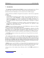
ABSTRACT
The ELMB128 is designed as a general-purpose plug-on module for distributed monitoring
and control applications in the ATLAS experiment. After production it contains a CANopen
application program for doing digital and analog input and output.
This document provides a description and user manual of the application and includes a full
listing of its Object Dictionary.
1
ELMB software
v2.0 12-Nov-2003
Contents
1
INTRODUCTION.............................................................................................................. 3
2
HARDWARE CONFIGURATION.................................................................................. 5
3
THE ELMBIO APPLICATION........................................................................................ 6
3.1 INITIALISATION............................................................................................................... 6
3.2 ANALOG INPUTS ............................................................................................................. 7
3.2.1 ADC Configuration................................................................................................. 7
3.2.2 Calibration Constants............................................................................................. 7
3.2.3 PDO Readout .......................................................................................................... 7
3.2.4 Readout on Change................................................................................................. 9
3.2.4.1
3.2.4.2
3.3
3.4
3.5
3.6
Delta-Mode........................................................................................................................................ 10
Window-Mode ................................................................................................................................. 11
DIGITAL INPUTS............................................................................................................ 13
DIGITAL OUTPUTS ........................................................................................................ 14
ANALOG OUTPUTS........................................................................................................ 14
STORING PARAMETERS AND SETTINGS ......................................................................... 15
4
EEPROM MEMORY MAP ............................................................................................ 17
5
OBJECT DICTIONARY................................................................................................. 19
6
EMERGENCY OBJECTS .............................................................................................. 30
REFERENCES........................................................................................................................ 32
Version History
Version Date
Comments
2.0
12 Nov 2003
First version describing ELMBio v4.2 for ELMB128.
1.x
…
Versions describing ELMBio v3.x for ELMB.
Table 1.
Document change record.
2
ELMB software
v2.0 12-Nov-2003
1 Introduction
The Embedded Local Monitor Board (ELMB) is a plug-on board designed for the ATLAS
experiment, where it will be used for a range of different control and monitoring tasks.
Full details about the ELMB hardware can be obtained from the ELMB webpages1.
During production the ELMB’s ATmega128 microcontroller is fitted with two application
programs:
1. a Bootloader:
in the ELMB microcontroller the upper 8 Kbyte of the 128 Kbyte flash memory is reserved for the socalled Bootloader, a separate application that takes care the InApplication-Programming. At the time of production of the ELMB, a Bootloader is installed, called ELMBbl, which enables reprogramming of the ELMB microcontroller via
the CAN-bus using the CANopen protocol. This Bootloader is described in a separate
document.
2. a CANopen I/O application for production acceptance testing and subsequent use as a
general-purpose analog/digital input and output application. This application, called
ELMBio, is the subject of this document.
ELMBio has been developed to provide users of the ELMB with a ready-to-use CANopen
module, when plugged onto the ELMB Motherboard.
It supports by means of the ELMB's onboard ADC and multiplexors –if present– 64 analog
input channels, up to 16 digital inputs (microcontroller PORTF and PORTA) and up to 16
digital outputs (microcontroller PORTC and PORTA). In addition it has support for an external DAC-module (result of a separate development), and can handle up to 64 analog outputs
The ELMBio application conforms where possible to the CANopen DS-401 Device Profile
for I/O-modules [5].
The socalled "process data" –in the case of ELMBio, the analog and digital inputs and outputs– can efficiently be read out (or written to) using CANopen PDO (Process Data Object)
messages. A PDO message is a non-confirmed CAN-message with one sender and one or
more receivers, containing no protocol overhead, only data (1 to 8 bytes). Receivers of a PDO
message know the meaning of the data content of a PDO message (in any case the receivers
may also find out about the data content of a PDO by consulting the PDO Mapping Parameters in the Object Dictionary of the producer of the PDO).
ELMBio supports a total of 5 PDOs: two Transmit-PDO for the analog inputs (one for raw
ADC-counts and one for physical values (µVolts)), one Transmit-PDO for the digital inputs,
one Receive-PDO for the digital outputs and a Receive-PDO for the analog outputs.
For an overview of the complete Object Dictionary (OD) of the ELMBio application see
section 5.
1
http://elmb.web.cern.ch/
3
ELMB software
v2.0 12-Nov-2003
Many of the features are configurable using standard CANopen messages. Settings can be
stored permanently in onboard EEPROM, also using standard CANopen messages.
ELMBio provides, apart from the standard CANopen and CANopen Device Profile features,
additional support for In-Application-Programming via the CAN-bus through interaction with
the Bootloader, and is equipped with a number of mechanisms to decrease the sensitivity of
the application to SEE (Single Event Effects) due to radiation.
The source code of ELMBio source code is freely available for users who want to customize
the application to fit their needs. Alternatively, there is also a CANopen firmware framework
available, for users who need to develop custom I/O and control themselves, but want to have
the benefit of a ready-to-use framework that handles all CAN and CANopen communication.
4
ELMB software
v2.0 12-Nov-2003
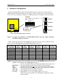
2 Hardware Configuration
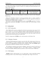
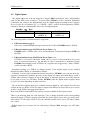
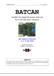
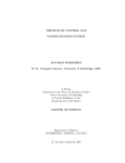
Using the onboard DIP-switches a node identifier must be set between 1 and 63 (must be
unique on the CAN-bus the module is on), using 6 of the 8 switches, and a CAN-bus bit rate
of 50, 125, 250 or 500 kbit/s, using the 2 remaining switches. See Figure 1 below for details.
Node-ID
(up=0, down=1; shown here = 17)
Bits : 5 4 3 2 1 0
ELMB top side
50 kbit/s
125 kbit/s
1234 5678
ATmega
128
250 kbit/s
CAN
baudrate
500 kbit/s
Programmer/RS232 adapter connector
Figure 1. Location and function of ELMB DIP-switches and the 10-pin Programmer/RS232 adapter connector.
Table 2 shows the functions of the ELMB microcontroller I/O pins. They match the I/O-pin
layout for an ELMB plugged on the ELMB Motherboard (version 3).
I/O PORT:
Function:
pin 0
pin 1
pin 2
pin 3
pin 4
pin 5
pin 6
pin 7
A
B
C
D
E
F
In/Out
in/out8
in/out9
in/out10
in/out11
in/out12
in/out13
in/out14
in/out15
In/Out
—
In/Out
out0
out1
out2
out3
out4
out5
out6
out7
In/Out
—
—
—
In/Out
—
—
—
ADC_CS
ADC_SCLK
ADC_SDI
ADC_SDO
ADC_MUX
DAC_CS1
DAC_CS2
DAC_CS3
DAC_CS4
I/O/ADC
in0
in1
in2
in3
in4
in5
in6
in7
SCLK
SDI
SDO
—
—
—
—
Table 2. I/O pin functions on the ATmega128 processor in the ELMBio application (use the
ELMB in combination with ELMB Motherboard v3):
—
= used for varioud ELMB-specific functions (DIP-switch readout, etc).
SCLK/SDI/ = lines carrying SPI-protocol for the onboard CAN-controller;
SDO
available externally; do not use for devices with slow optocouplers.
AD_xxx
= SPI signals for the ELMB onboard ADC and external DAC-modules.
ADC_xxx = control signals for the ELMB onboard ADC.
DAC_CSx = select signals for the external DAC modules.
inn, outn
= digital input n (0<n<15) or digital output n (0<n<15),
respectively; pins on PORTA are individually configured as either
input or output.
5
ELMB software
v2.0 12-Nov-2003
3 The ELMBio Application
3.1
Initialisation
After power-up, watchdog reset, manual reset or a CANopen initiated reset action (i.e. by an
NMT Reset-Node message, see below) a CANopen node sends a socalled Boot-up message
(as defined by the CANopen standard) as soon as it has finished initialising (hardware, software); this is a CAN-message with the following syntax:
ELMBio (NMT-Slave)
→
Host (NMT-Master)
COB-ID
700h + NodeID
DataByte 0
0
NodeID is the CAN node identifier set by means of the ELMB onboard DIP-switches, which
according to the CANopen standard must be in the range between 1 and 127 and for ELMBio
can be to set to a value between 1 and 63, as shown in Figure 1.
To start the ELMBio application in the CANopen sense of the word, the following CANopen
NMT (Network ManagemenT) message must be sent:
Host (NMT-Master) → ELMBio (NMT-Slave)
COB-ID
000h
DataByte 0
1
(Start_Remote_Node)
There is no reply to this message.
DataByte 1
NodeID or 0
(all nodes on the bus)
Now ELMBio is Operational, meaning that it monitors I/O channels as required and sends
and receives (and processes) PDO messages (carrying the application data).
Optionally a feature called auto-start may be enabled, so that ELMBio automatically goes to
Operational state after power-up or reset. The auto-start feature can be configured in OD index 3200h, subindex 2.
To generate a soft reset to ELMBio the following CANopen NMT message must be sent:
Host (NMT-Master) → ELMBio (NMT-Slave)
COB-ID
000h
DataByte 0
1
(Reset_Node)
Again, there is no reply to this message.
DataByte 1
NodeID or 0
(all nodes on the bus)
6
ELMB software
v2.0 12-Nov-2003
Note that at power-up it is the Bootloader application firmware that becomes active first and
is in control of the ELMB; it reports its presence by sending the following Emergency message (see also section 6):
Bootloader
COB-ID
080h +
NodeID
→
Host
Byte 0-1
Emergency
Error Code
(00h 50h)
Byte 2
Error Register
(Object 1001h)
(80h)
Byte 3-7
Manufacturer specific error field
(FEh 01h 28h ZZh 00h)
(ZZh = MCUCSR)
(MCUCSR = MCU Control and Status Register; for details see section 6 or the ATmega128
datasheet [3]).
Having the Bootloader activated at power-up guarantees that it is always possible to
download new application software to the ELMB, even when the application currently programmed in the ELMB is faulty or corrupted.
After about 4 s the Bootloader automatically jumps to the ELMBio application. The Bootloader jumps immediately to ELMBio, if it receives an NMT Reset-Node message, as shown
above.
3.2
Analog Inputs
3.2.1 ADC Configuration
The ELMB's ADC [6] can be configured for full-scale measurement in the ranges 25 mV,
55 mV, 100 mV, 1V, 2.5V and 5V, unipolar or bipolar, with a programmable conversion wordrate of 1.8 Hz, 7.5 Hz, 15 Hz, 30 Hz, 60 Hz, 85 Hz or 100 Hz (in practice the achievable rate
of conversions is limited to about 30 Hz maximum due to the slow opto-couplers used in the
(serial) interface between the processor and the ADC.
The ADC configuration in ELMBio can be read from and set in OD index 2100.
3.2.2 Calibration Constants
During the ELMB production acceptance tests each of the ADC voltage ranges (for one conversion wordrate, i.e. 15 Hz) is calibrated and the resulting calibration constants have been
stored in the ELMB EEPROM. Depending on the configured voltage range ELMBio applies
the appropriate calibration constants to the ADC conversion data.
The calibration constants are also stored in a database, and can be retrieved on the basis of
the serial number of the ELMB, which is a 32-bit number (actually, a 4-character string),
stored in the ELMB’s EEPROM, and also printed on a sticker located on the ELMB PCB.
3.2.3 PDO Readout
ELMBio sends one PDO message for every analog input. It either sends PDO messages
containing the ADC count or PDO messages containing the input voltage in microVolts.
7
ELMB software
v2.0 12-Nov-2003
The CAN-identifier used for the ADC readout in counts is the socalled 2nd-transmit-PDO
(TPDO2) of the CANopen Predefined Connection Set, i.e. COB-ID = 280h + NodeID.
The TPDO2 message is a 4-byte message and is formatted as follows:
ELMBio → Host
TPDO2 COB-ID
DataByte 0
DataByte 1
DataByte 2-3
280h+NodeID
Channel Number
Chan status+config
ADC value
with:
ADC value:
16-bits value, LSB in byte 2, MSB in byte 3.
Channel Number:
number between 0 and 63.
Chan status+config: bit 7: Conversion status: 1=ERROR (overflow or oscillation), 0=OKAY.
bits 6-0: ADC configuration: conversion wordrate (bits W0, W1 and
W2), gain range (bits G0, G1 and G2) and unipolar or bipolar (bit U/B);
see below.
BIT
Meaning
7
Error
6
W2
5
W1
4
W0
3
G2
2
G1
1
G0
0
U/B
The CAN-identifier used for the ADC readout in µV is the socalled 3rd-transmit-PDO
(TPDO3) of the CANopen Predefined Connection Set, i.e. COB-ID = 380h + NodeID.
The TPDO3 message is a 6-byte message and is formatted as follows:
ELMBio → Host
TPDO3 COB-ID
DataByte 0
DataByte 1
380h+NodeID
Channel Number
Chan status+config
with:
ADC value:
32-bits signed value in µV, LSB first.
Channel Number:
number between 0 and 63.
Chan status+config: see above.
DataByte 2-5
ADC value [µV]
The number of analog channels can be set to any value up to 64 by writing to OD index
2100h, sub 1.
The way in which all 64 (or less) analog inputs are read out depends on the transmissiontype of TPDO2 or TPDO3. The analog inputs are read out according to the PDO transmission
type after power-up. Alternatively the user can set the transmission type to the required value
by writing to ELMBio’s Object Dictionary (to OD index 1801h, sub 2 or OD index 1802h,
sub 2), and possibly stores it permanently in onboard EEPROM so that it will be the default
transmission type after every subsequent reset or power-up.
The following modes of transmission are supported:
•
PDO transmission type 1:
after every socalled SYNC message issued on the CAN-bus ELMBio starts an analog
input channel scan and sends (up to) 64 TPDO messages, one message for every analog
input channel, as shown above. An A/D conversion has to be done for every channel so
it can take up to about 30 seconds before all TPDOs have been sent (the ADC conversion rate can be as low as 1.88 Hz).
8
ELMB software
v2.0 12-Nov-2003
The SYNC message is a CAN-message with a fixed COB-ID and no data bytes:
Host
→
all (SYNC-)slave nodes
COB-ID
080h
Note that all nodes that have PDOs configured to respond to a SYNC will respond to the
SYNC broadcast message.
Note also that if both TPDO2 and TPDO3 have transmission type 1 only TPDO3 messages are produced (unless there are no (valid) calibration constants for the currently active ADC voltage range).
•
PDO transmission type 255 and Event Timer = 0:
after every socalled Remote Transmission Request (RTR) for TPDO2/3 ELMBio starts
an analog input channel scan and sends (up to) 64 TPDO2/3 messages, one message for
every analog input channel. The CAN Remote Frame that constitutes this RTR has no
data bytes and looks like this:
Host
→
ELMBio
COB-ID
280h + NodeID
Note that an RTR is sent to and processed by only one particular node.
•
PDO transmission type 255 and Event Timer > 0:
If TPDO2’s event timer (OD index 1801h, sub 5) or TPDO3’s event timer (OD index
1802h, sub 5) is set to a value unequal to zero (event timer is expressed in units of 1 s)
ELMBio automatically starts an analog input channel scan (resulting in up to 64 TPDO2
or TPDO3 messages) triggered by a timer with a period equal to the event timer setting
(in this mode an RTR also triggers such an input scan). If the timer expires while a channel scan is still in progress, the trigger is ignored until the next timer expiration.
Optionally ELMBio does a reset and calibration sequence before each ADC channel scan.
This feature is controlled via OD index 2120h (may be useful for increasing radiation tolerance of the ADC readout).
Analog inputs can of course also be read using CANopen SDO messages (see OD index
6404h for readout of ADC channels in ADC counts and OD index 2404h for readout of ADC
channels in µV).
3.2.4 Readout on Change
ELMBio has 2 modes of readout-on-change for analog inputs: delta-change mode and window mode. These modes can be enabled individually and both may be enabled at the same
time. Use OD index 2130h to enable or disable delta-change mode and OD index 2140h to
enable or disable window mode.
When the global readout-on-change interrupt for analog inputs is enabled (OD index 6423h
set to 1) and any one of the delta-change or window modes is enabled, ELMBio starts a con9
ELMB software
v2.0 12-Nov-2003
tinuous loop doing conversions of the number of configured ADC channels (OD index 2100h,
sub 1) as soon as it is put into Operational state.
Now every time a channel’s 'status' changes (depending on the mode and settings), a TPDO3
is generated (containing the ADC channel reading in µV). Readout-on-change never generates
a TPDO2 (with ADC reading in counts), unless the calibration constants are not present or
invalid for the currently active ADC voltage range). If both modes are enabled and a channel
satisfies both readout-on-change conditions in the same channel scan cycle, only one message
is sent for this channel.
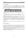
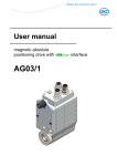
3.2.4.1 Delta-Mode
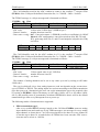
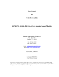
In delta-change mode analog input read-out ELMBio asynchronously sends a message
when an analog input channel reading has increased or decreased by a certain preset amount.
After the message has been sent the current analog reading is taken as the new reference value
for this channel in the scanning loop.
The analog channel input reference values are stored in RAM but not protected against SEE,
since it is not necessarily considered a bad thing when an analog input channel reading is sent
again just because the reference value in RAM has been corrupted by chance. The (corrupted)
reference value gets immediately overwritten by the new reading.
When the node is put into Operational state the ADC reference values are initialized by the
readings from the first ADC-channel scan cycle.
An explicit request for data such as a SYNC or a RTR (Remote Frame) message stops/aborts
the ongoing channel scan cycle and starts a new scan cycle in which all analog input values
are forcibly sent as TPDO2 or TPDO3 messages (i.e. raw ADC counts or voltage values, depending on the TPDO2 and TPDO3 transmission modes and the RTR that triggered the action), i.e. a ‘forced-readout’ ADC scan cycle is started.
In addition, if the transmission mode of the appropriate PDO is set to 255 and the PDO
Event Timer set to a value greater than zero the scan cycle is aborted at regular intervals according to the configured interval and a ‘forced-readout’ scan cycle is started. A ‘forcedreadout’ scan cycle does not affect the currently stored analog input channel reference values.
The delta-change parameter (the amount by which an ADC input channel value has changed
when its reading is sent in a message) can be changed on a per-channel basis (on-the-fly) and
can be written or read, expressed only in units of µVolt (by writing to or reading from OD index 6426h). A value of zero for the delta-change parameter effectively disables the check for
the channel in question.
In addition, the delta-change parameter for all channels can be set to the same value in one
write-operation to OD index 6426h using subindex 255 (=FFh).
These parameters are stored onboard in non-volatile memory on request, in the CANopen
standard way.
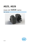
The delta-change mode of analog input readout is illustrated in Figure 2.
10
ELMB software
v2.0 12-Nov-2003
130
Analog In
120
DELTA=10
110
samples
100
90
sample
is sent
ELMBio put into
Operational state
80
1
2
3
4
5
6
7
8
9
10
Time
Figure 2. Illustration of the analog input delta-change mode. The delta-change parameter is set to 10. Analog input samples marked by an arrow are sent.
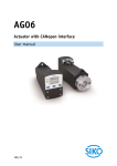
3.2.4.2 Window-Mode
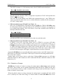
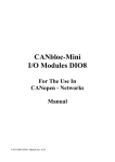
In window mode analog input read-out ELMBio asynchronously sends a message when an
analog input channel reading has gone below a certain preset lower limit or has exceeded a
certain preset upper limit.
The response to a SYNC or a RTR is similar to the behaviour described in the section on the
delta-mode.
The upper- and lower-limit parameter can be changed on a per-channel basis (on-the-fly)
and can be written or read, expressed only in units of µVolt (by writing to or reading from OD
index 6424h or 6425h resp.). Upper and lower limit must differ by at least 1 ADC count to
work, so this minimum difference in µVolt varies according to the ADC configuration.
In addition the upper- and lower-limit parameters for all channels can be set to the same
value in one write-operation to OD index 6424h and 6425h resp. using subindex 255 (=FFh).
These parameters are stored onboard in non-volatile memory on request, in the CANopen
standard way.
After a channel’s reading has crossed a limit –either going outside the window or going back
inside the window– a single message is sent. When going outside the window a message is
sent only after a configurable number of consecutive readings outside the set window. We call
11
ELMB software
v2.0 12-Nov-2003
this number the exceed counter. There is only one counter for all channels, set in OD index
2150h.
When the channel reading returns inside the window a message is sent immediately (but
only if the 'outside-window' situation was reported !).
Two readings are consecutive when they occur in 2 consecutive channel scan cycles. Note
that if 64 ADC channels are scanned, there may be considerable time between 2 consecutive
readings of the same channel (in the order of several seconds, depending on the number of
channels in the scan cycle and the ADC conversion wordrate used).
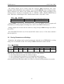
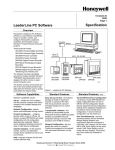
The window mode of analog input readout is illustrated in Figure 3.
UPPER=120, LOWER=80, CNTR=2
130
120
Analog In
110
samples
100
90
80
70
sample
is sent
ELMBio put into
Operational state
1
3
5
7
9
11
13
15
Time
Figure 3. Illustration of the analog input window mode. The upper limit of the window
is set to 120 and the lower limit to 80. The exceed counter is set to 2. Analog
input samples marked by an arrow are sent.
12
ELMB software
3.3
v2.0 12-Nov-2003
Digital Inputs
The digital inputs are read out using the CANopen PDO mechanism. The CAN-identifier
used for this PDO is the socalled 1st-transmit-PDO (TPDO1) of the CANopen Predefined
Connection Set, which is the default PDO used for digital inputs according to the CANopen
Device Profile for I/O Modules [5], i.e. COB-ID = 180h + NodeID. In this application TPDO1
contains 2 data byte containing the state of the 2x8 digital inputs:
ELMBio → Host
TPDO1 COB-ID
180h+NodeID
DataByte 0
8-bit Digital Input
(PORTF in)
DataByte 1
8-bit Digital Input
(PORTA in)
The following modes of transmission are supported:
•
PDO transmission type 1:
after every socalled SYNC message issued on the CAN-bus ELMBio sends a TPDO1.
•
PDO transmission type 254/255 and Event Timer = 0:
ELMBio sends a TPDO1 after every socalled Remote Transmission Request (RTR) for
the PDO.
•
PDO transmission type 254/255 and Event Timer > 0:
If TPDO1’s event timer (OD index 1800h, sub 5) is set to a value unequal to zero (event
timer is expressed in units of 1 ms, but here its value is truncated to a multiple of 1000)
ELMBio automatically sends a TPDO1 on a regular basis triggered by a timer (TPDO1
is also sent after a RTR).
Automatic sending of a TPDO1 at 'change-of-state' of the digital inputs can be enabled
through OD index 6005h; it is disabled by default.
If enabled, in each of the transmission modes listed above, ELMBio, once put into state Operational, continuously monitors the state of the digital I/O inputs and immediately sends a
TPDO1 after it detects a change in any of the inputs. A debounce time-out is in effect and can
be set (also to zero; see OD index 2200h). ELMBio polls the digital inputs roughly about
every 0.5 ms, also depending on other activities.
The second 8-bit digital input port is shared between digital in- and outputs. See the next
section on how to define a bit to be input or output. Bits defined as output show up as zeroes
in byte 1 in the TPDO1 message shown above.
Note: both PORTA and PORTF have pull-up resistors enabled in their input circuits.
There is an interrupt mask for each input bit: if set, a change detected on the corresponding
input will trigger a TPDO1 message (provided the global digital input interrupt enable mentioned above in OD index 6005h is set); the interrupt masks can be set in OD index 6006h,
sub 1 and 2.
Digital inputs can of course also be read using CANopen SDO messages (see OD index
6000h).
13
ELMB software
3.4
v2.0 12-Nov-2003
Digital Outputs
The digital outputs can be written using the CANopen PDO mechanism. The CAN-identifier
used for this PDO is the socalled 1st-receive-PDO (RPDO1) of the CANopen Predefined
Connection Set, which is the default PDO used for digital outputs according to the CANopen
Device Profile for I/O Modules [5], i.e. COB-ID = 200h + NodeID. RPDO1 has at least 1 data
byte, containing in each byte the (required) state of 8 digital outputs:
Host → ELMBio
RPDO1 COB-ID
200h + NodeID
DataByte 0
8-bit Digital Output
(PORTC out)
DataByte 1
8-bit Digital Output
(PORTA out)
If RPDO1 carries only 1 data byte only PORTC gets new settings, PORTA remains unchanged.
Once ELMBio is put into state Operational it can receive the RPDO1 and immediately on
reception sets its digital outputs according to the values in the RPDO1 data byte(s).
ELMBio retains the digital output settings only after a 'soft' reset (triggered by an NMT Reset-Node message). After a 'hard' reset (power-up, watchdog) the outputs are initialized to either 0 or 1 (low or high), which can be set by OD index 2300h.
As mentioned in the previous section the second 8-bit digital port can be defined bit-by-bit
as either input or output. This is done through the socalled Output Filter Mask (OD index
6208h, sub 2): bits set to 1 in this mask are output, the other bits are automatically defined as
input. Bits defined as input in byte 1 in the RDPO1 message shown above are ignored when
setting the outputs.
Digital outputs can of course also be written to using CANopen SDO messages (see OD index 6200h).
3.5
Analog Outputs
Analog outputs are compatible with the DAC-module designed and built for ATLAS DCS
applications (described elsewhere), either equipped with MAX5122 DACs or MAX525
DACs. With the MAX5122 one DAC-module has 4 channels, when equipped with the
MAX525 one DAC-module has 16 channels. By default ELMBio assumes MAX5122-type
DACs. By setting the proper parameter in OD index 2500h MAX525-type DACs can be selected. The two types of DAC-module can not be mixed.
Four DAC-modules can be connected (i.e. directly to the 20-pin J8 connector on the ELMB
Motherboard), for a total of up to 64 analog output channels when using MAX525 DACs, or
16 channels when using MAX5122 DACs.
14
ELMB software
v2.0 12-Nov-2003
The analog outputs can be written using the CANopen PDO mechanism. The CANidentifier used for this PDO is the socalled 2st-receive-PDO (RPDO2) of the CANopen Predefined Connection Set, which is the default PDO used for analog outputs according to the
CANopen Device Profile for I/O Modules [5], i.e. COB-ID = 300h + NodeID. RPDO2 has at
least 3 data bytes, containing the DAC channel number and a 2-byte DAC-value:
Host → ELMBio
RPDO2 COB-ID
300h + NodeID
DataByte 0
Channel Number
DataByte 2-3
DAC value
Once ELMBio is put into state Operational it can receive the RPDO2 and on reception will
immediately set analog outputs according to the values in the RPDO2 data byte(s).
Analog outputs can of course also be written to, using CANopen SDO messages (see OD index 6411h).
Note that MAX5122 DACs are 12-bit, but the DAC-value is set as a 13-bit value with bit 0
always equal to 0.
3.6
Storing Parameters and Settings
Parameters and settings can be stored permanently onboard (in an EEPROM) by writing
string "save" to OD index 1010h. The CANopen SDO mechanism is used to do this:
→
ELMBio
DataByte
COB-ID
0
1
600h +
23h
10h
NodeID
Host
2
10h
3
subindex
4
73h
('s')
5
61h
('a')
6
76h
('v')
7
65h
('e')
with OD index 1010h in byte 1+2 and subindex in byte 3 with subindex:
= 1: store all parameters (as listed for subindex 2 and 3).
= 2: store communication parameters (concerning PDO and Guarding).
= 3: store application parameters (concerning ADC, DAC and Digital I/O).
(check out the Object Dictionary tables in section 5 to find out which parameters are stored).
15
ELMB software
v2.0 12-Nov-2003
If the store-operation succeeded ELMBio sends the following reply:
ELMBio
→
Host
DataByte
COB-ID
0
580h +
60h
NodeID
1
10h
2
10h
3
subindex
4
–
5
–
6-7
–
If the store-operation did NOT succeed ELMBio sends the following reply (SDO Abort
Domain Transfer, error reason: ‘hardware fault’ (for details see [1])):
→
Host
DataByte
COB-ID
0
1
580h +
80h
10h
NodeID
ELMBio
2
10h
3
subindex
4
0
5
0
6
6
(Error Code)
7
6
(Error Class)
Parameters can be reset to their default values (by invalidating the corresponding contents of
the EEPROM) by writing to OD index 1011h, using this time the string "load" (6Ch, 6Fh,
61h, 64h) in bytes 4 to 7 of the SDO. Note that the default values take effect only after a subsequent reset of the node. Default values are listed in the OD tables in section 5.
The tables with the Object Dictionary in section 5 show the settings stored in EEPROM as
marked by an asterisk (*).
Note that storage of ELMB Serial Number and ADC calibration constants in EEPROM are
handled separately.
16
ELMB software
v2.0 12-Nov-2003
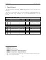
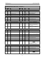
4 EEPROM Memory Map
Table 3 and Table 4 detail the layout of the ELMB’s EEPROM in the ELMBio application.
Addresses 800h - FFFh (2048 bytes) are not used.
EEPROM
not used
ADDR
0000
0001
Holds permanently saved application configuration and settings, stored in up to 8 blocks of
up to 16 bytes each; includes a CRC checksum
for each data block.
ELMBio
configuration
parameters
Rad-tolerant
working copy
of global
settings
and
parameters
DESCRIPTION
00A1
00A2
00E8
Holds a copy of most application configuration and settings and some other parameters
that don't change very often; parameters are
reread from EEPROM each time before being
used; this is an optional feature to counter the
effects of SEE (Single Event Upset).
00E9
not used
ELMB
Serial
Number
00FF
0100
0106
0107
not used
011F
0120
ELMB
Analog-in
calib consts
01CF
Holds the ELMB Serial Number given to it at
production time; serves to uniqely identify the
ELMB and retrieve its calibration constants
and/or production data in the ELMB production database.
Holds the calibration constants, which were
determined at production time, for all 6 voltage ranges (note: only present for ELMBs
with an analog input part).
Table 3. EEPROM memory map for ELMBio application (addresses 000h - 1CFh)
(continued on the next page).
17
ELMB software
v2.0 12-Nov-2003
EEPROM
ADDR
DESCRIPTION
01E0
not used
Deltas
working
copy
01FF
0200
02BF
Holds a 3-byte value (unsigned µVolts) for
each analog input, i.e. 64x3 bytes = 192 bytes.
02C0
not used
Deltas
permanent
storage + CRC
02FF
0300
03C2
Holds a 3-byte value (unsigned µVolts) for
each analog input, i.e. 64x3 bytes = 192 bytes,
plus a 2-byte CRC, plus a 'valid' token byte.
03C3
not used
Upper Limits
working
copy
03FF
0400
Holds a 3-byte value (signed microVolts) for
each analog input, i.e. 64x3 bytes = 192 bytes.
04BF
04C0
not used
Upper Limits
permanent
storage + CRC
04FF
0500
05C2
Holds a 3-byte value (signed µVolts) for each
analog input, i.e. 64x3 bytes = 192 bytes,
plus a 2-byte CRC, plus a 'valid' token byte.
05C3
not used
Lower Limits
working
copy
05FF
0600
06BF
Holds a 3-byte value (signed µVolts) for each
analog input, i.e. 64x3 bytes = 192 bytes.
06C0
not used
Lower Limits
permanent
storage + CRC
06FF
0700
07C2
Holds a 3-byte value (signed µVolts) for each
analog input, i.e. 64x3 bytes = 192 bytes,
plus a 2-byte CRC, plus a 'valid' token byte.
07C3
not used
07FF
Table 4. EEPROM memory map for ELMBio application (addresses 1E0h - 7FFh).
18
ELMB software
v2.0 12-Nov-2003
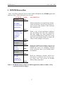
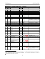
5 Object Dictionary
The Object Dictionary (OD) of the ELMBio v4.2 application is listed in the tables on the
next pages.
The values of objects marked with '∗' in the Index column are stored in EEPROM for permanent non-volatile storage, on request. They are retrieved from EEPROM at reset and
power-up.
Communication Profile Area
Index
(hex)
Sub
Index
Description
Data/
Object
Attr
1000
-
Device type
U32
RO
000F0191h
1001
1002
-
Error register
Manufacturer status reg
U8
U32
RO
RO
0
0
1008
1009
100A
0
VisStr
VisStr
VisStr
RO
RO
RO
"ELMB"
"el40"
"MA42"
1
Manufacturer device name
Manufacturer hw version
Manufacturer software
version
minor version number
VisStr
RO
"0001"
-
Guard time [ms]
Life time factor
U16
U8
RO
RW
1000
0
100C
100D
*
1
2
Default
Comment
Meaning: DSP-401 device profile, analogue in- and outputs,
digital in- and outputs on device
1
(see footnote)
= Embedded Local Monitor Board
= ELMB V4
ELMBio application version 4.2
2
(see footnote)
= 1 second
Lifeguarding timeout in seconds;
0 → no lifeguarding timeout
Manufacturer Status Register bits:
00000001: ADC reset error,
00000002: ADC calibration error,
00000004: ADC conversion time-out,
00000008: error reading or writing ADC calibration constant(s),
00000010: error reading or writing ADC delta-change parameters,
00000020: error reading or writing ADC upper-limit parameters,
00000040: error reading or writing ADC lower-limit parameters.
"MA": version using the ELMB onboard ADC, "MV": version using the ATmega128 on-chip 8-chan ADC,
"MN": version without any ADC support.
19
ELMB software
v2.0 12-Nov-2003
Communication Profile Area
Index
(hex)
Sub
Index
Attr
Default
Array
U8
U32
RO
RW
5
1
Save communication parameters
Save application parameters
U32
RW
1
U32
RW
1
Save ADC delta-change
parameters
Save ADC upper/lower
limit parameters
U32
RW
1
U32
RW
1
Restore default parameters
Array
0
1
Highest index supported
Set all parameters to defaults
U8
U32
RO
RW
5
1
2
Set communication parameters to defaults
Set application parameters
to defaults
U32
RW
1
U32
RW
1
Set ADC delta-change parameters to defaults
Set ADC upper/lower limit
parameters to defaults
U32
RW
1
U32
RW
1
Producer Heartbeat Time
[1 s]
U16
RW
0
Identity
Number of entries
Vendor ID
Record
1..4
U32
RO
RO
1
12345678h
1010
0
1
2
3
4
5
1011
3
4
5
1017
*
-
1018
0
1
Description
Data/
Object
Store parameters
Highest index supported
Save all parameters
Comment
Save stuff in onboard EEPROM
Read: 1; Write "save": store all
(incl. ADC limits)
Read: 1; Write "save": store
PDO par's, Life time factor, …
Read: 1; Write "save": store
ADC config, dig.I/O config, …
(incl. ADC limits)
Read: 1; Write "save": store
ADC deltas
Read: 1; Write "save": store
ADC upper/lower liimits
Invalidate stuff in onboard
EEPROM; use defaults
Read: 1; Write "load": invalidate
all parameters stored
(excl. ADC deltas/limits)
Read: 1; Write "load": invalidate stored PDO par's, etc.
Read: 1; Write "load": invalidate stored ADC config, etc.
(excl. ADC deltas/limits)
Read: 1; Write "load": invalidate
ADC deltas
Read: 1; Write "load": invalidate
ADC upper/lower limits
In units of seconds (but <=255 !),
(NB: should be in ms according to
CANopen!);
0 → Heartbeat is disabled
Mandatory CANopen object
20
to be ordered from CiA
ELMB software
v2.0 12-Nov-2003
Communication Profile Area (continued…)
Index
(hex)
Sub
Index
Description
Data/
Object
1st Receive PDO par's
Number of entries
COB-ID used by PDO
Record
U8
U32
Transmission type
Not used
U8
2nd Receive PDO par's
Number of entries
COB-ID used by PDO
Record
U8
U32
Transmission type
Not used
U8
0
1
1st Receive PDO mapping
Number of entries
Digital outputs 1-8
2
1400
0
1
2
3,4,5
1401
0
1
RO
RO
According to CANopen Predefined Connection Set
Only 255 allowed
Data type = PDOCommPar
2
62000108
Digital outputs 9-16
U32
RO
62000208
0
1
2
2nd Receive PDO mapping
Number of entries
DAC channel number
16-bit analog output
Record
U8
U32
U32
RO
RO
RO
2
64110008
64110110
0
1
1st Transmit PDO par's
Number of entries
COB-ID used by PDO
Record
U8
U32
RO
RO
2
3
4
5
Transmission type
Inhibit time [100 µs]
Not used
Event timer [1 s]
U8
U16
U8
U16
RW
RO
RO
RW
5
180h +
NodeID
1
0
0
0
0
1
2nd Transmit PDO par's
Number of entries
COB-ID used by PDO
Record
U8
U32
RO
RO
2
3
4
5
Transmission type
Inhibit time [100 µs]
Not used
Event timer [1 s]
U8
U16
U8
U16
RW
RO
RO
RW
1801
Comment
Data type = PDOCommPar
RO
RO
1800
*
5
200h +
NodeID
255
0
Record
U8
U32
1601
*
RO
RO
RO
RO
1600
*
Default
5
300h +
NodeID
255
0
2
3,4,5
*
Attr
RO
RO
According to CANopen Predefined Connection Set
Data type = PDOMapping
OD index 6200, sub-index 1:
Outputs 1-8 (see DSP-401),
size = 8 bits
OD index 6200, sub-index 2:
Outputs 9-16 (see DSP-401),
size = 8 bits
Data type = PDOMapping
actually not allowed, but…
OD index 6411, sub-index 1:
16-bits Analog Output (see DSP401), size = 16 bits, multiplexed
Data type = PDOCommPar
According to CANopen Predefined Connection Set
Only 1 and 255 allowed
not used
In units of seconds
(NB: should be in ms according
to CANopen!); active if >0 and
transmission-type = 255
Data type = PDOCommPar
21
5
280h +
NodeID
1
0
0
0
According to CANopen Predefined Connection Set
Only 1 and 255 allowed
not used
In units of seconds (NB: should be
in ms according to CANopen!);
active if >0 and transm-type = 255
ELMB software
v2.0 12-Nov-2003
Communication Profile Area (continued…)
Index
(hex)
Sub
Index
Description
Data/
Object
Attr
Default
0
1
3rd Transmit PDO par's
Number of entries
COB-ID used by PDO
Record
U8
U32
RO
RO
Transmission type
Inhibit time [100 µs]
Event timer [1 s]
U8
U16
U16
RW
RO
RW
5
380h +
NodeID
1
0
0
2
3
5
0
1
1st Transmit PDO mapping
Number of entries
Digital inputs 1-8
Record
U8
U32
RO
RO
2
60000108h
2
Digital inputs 9-16
U32
RO
60000208h
0
2nd Transmit PDO mapping
Number of entries
Record
U8
RO
2
1
2
ADC channel number
24-bit analogue input
U32
U32
RO
RO
64040008h
64040118h
0
3rd Transmit PDO mapping
Number of entries
Record
U8
RO
2
1
ADC channel number
U32
RO
24040008h
2
32-bit analogue input
U32
RO
24040128h
1802
*
*
1A00
1A01
1A02
Comment
Data type = PDOCommPar
According to CANopen Predefined Connection Set
Only 1 and 255 allowed
not used
In units of seconds
(NB: should be in ms according
to CANopen!); active if >0 and
transmission-type = 255
Data type = PDOMapping
22
OD index 6000, sub-index 1:
Inputs 1-8 (see DSP-401),
size = 8 bits
OD index 6000, sub-index 2:
Inputs 9-16 (see DSP-401),
size = 8 bits
Data type = PDOMapping
should be 255 for MuxPDO, but
this is not a CANopen MPDO…
actually not allowed, but…
OD index 6404, sub-index 1:
Analogue inputs, multiplexed,
size = 24 bits;
actually the ADC flag bits (present in OD index 6404) have
been replaced by a byte combining the ADC configuration and
the two ADC error flags
Data type = PDOMapping
should be 255 for MuxPDO, but
this is not a CANopen MPDO…
actually not allowed, but who
cares… it’s not important
Object 2404, sub-index 1:
Analogue inputs in volts,
multiplexed, size = 40 bits:
actually the ADC flag bits (present in Object 2404) have been
replaced by a byte combining the
ADC configuration and the two
ADC error flags; 24-bit data is
replaced by a 32-bit signed long
ELMB software
v2.0 12-Nov-2003
Manufacturer-Specific Profile Area
Index
(hex)
Sub
Index
Attr
Default
Record
U8
U8
RO
RW
21
64
U8
U8
U8
RW
RW
RW
0
4
1
5
Conversion Word Rate
Input Voltage Range
Unipolar/Bipolar
Measurement Mode
Power Save Mode
Bool
WO
6
7
8
9
10
11
12
13
14
15
Configuration Register
Offset Register #1
Gain Register #1
Offset Register #2
Gain Register #2
Offset Register #3
Gain Register #3
Offset Register #4
Gain Register #4
Channel-Setup Register #1
U32
U32
U32
U32
U32
U32
U32
U32
U32
U32
RW
RW
RW
RW
RW
RW
RW
RW
RW
RW
16
Channel-Setup Register #2
U32
RW
17
Channel-Setup Register #3
U32
RW
18
Channel-Setup Register #4
U32
RW
*
19
20
21
Conversion Word Rate
Input Voltage Range
SPI SCLK signal high
period (opto-coupler delay)
U8
U32
U8
RO
RO
RW
2110
-
ADC-reset-and-calibrate
U8
WO
2120
*
-
ADC-reset-and-calibrate
before each channel scan
Bool
RW
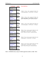
2100
*
0
1
*
*
*
2
3
4
Description
Data/
Object
ADC-configuration
Number of entries
Number of input channels
Comment
CRYSTAL CS5523 16-bit ADC
15
5000000
75
1
000: 15.0 Hz,
100: 101.1 Hz,
001: 30.0 Hz,
101: 1.88Hz,
010: 61.6 Hz,
110: 3.76 Hz,
011: 84.5 Hz,
111: 7.51 Hz
2
000: 100 mV,
001: 55 mV,
010: 25 mV,
011: 1 V,
23
0
can be set to actual number of
channels used
3-bit code 1
3-bit code 2
0 = bipolar, 1 = unipolar
1 = put ADC in power save mode
0 = take ADC out of this mode
CS5523 Config Register
CS5523 physical channel AIN1
CS5523 physical channel AIN1
CS5523 physical channel AIN2
CS5523 physical channel AIN2
CS5523 physical channel AIN3
CS5523 physical channel AIN3
CS5523 physical channel AIN4
CS5523 physical channel AIN4
LC 1 (12-bits) in lower 2 bytes,
LC 2 (12-bits) in upper 2 bytes
LC 3 (12-bits) in lower 2 bytes,
LC 4 (12-bits) in upper 2 bytes
LC 5 (12-bits) in lower 2 bytes,
LC 6 (12-bits) in upper 2 bytes
LC 7 (12-bits) in lower 2 bytes,
LC 8 (12-bits) in upper 2 bytes
in Hz
in µV
in µs, 10 <= value <= 255
Writing triggers a reset and calibrate sequence using the current
ADC settings
If =1 a reset/calibration sequence
is performed before every ADC
input channel scan
100: 5 V,
101: 2.5 V
ELMB software
v2.0 12-Nov-2003
Manufacturer-Specific Profile Area (continued…)
Index
(hex)
Sub
Index
Name
Data/
Object
Attr
Default
2130
*
-
Enable Analogue Input Interrupt Delta-change Mode
Bool
RW
1
2140
*
-
Bool
RW
0
2150
*
-
Enable Analogue Input Interrupt Upper/Lower Limit
Mode
Upper/Lower Limit Exceed
Counter
U8
RW
2
2200
*
-
Digital Input debounce
timer
U8
RW
10
In units of ca. 0.5 ms (set to 0
there is ca. 0.5 ms between consecutive input polls).
2300
*
-
Digital Output Init High
Bool
RW
1
After a hard reset:
if set to 0 Digital Outputs will be
initialised to all low;
if set to 1 Digital Outputs will be
initialised to all high
Read Analogue Input
Calibrated
Record
0
Number of analog inputs
U8
RO
1
Input 1
U32
RO
2
…
…
64
Input 2
…
…
Input 64
U32
…
…
U32
RO
…
…
RO
0
1
DAC configuration
Number of entries
Number of output channels
Record
U8
U8
RO
RO
3
16 or 64
*
2
MAX525 DAC Type Select Bool
RW
0
*
3
SPI SCLK signal high
period (opto-coupler delay)
RW
75
2404
2500
1
U8
64
Comment
Enable/disable delta mode
readout-on-change operation
(global enable: Object 6423)
Enable/disable window mode
readout-on-change operation
(global enable: Object 6423)
Number of consecutive readout
values outside window before
value is sent 1
8 bits status, 24 bits analogue
value, in µV
NB: read-out is refused if there
are no valid calibration constants
for the current ADC settings
Fixed, but actual hardware configuration may vary
(set in Object 2100, sub 1)
1st analog input: 8-bit flags +
24-bit (signed) data
2nd "
"
"
"
…
…
64th "
"
"
"
=16 when MAX5122 DAC used,
=64 when MAX525 DAC used
0: DAC-type is MAX5122
1: DAC-type is MAX525
in µs, 10 <= value <= 255
‘Consecutive’ here means: in consecutive input channel scans (of up to 64 channels).
24
ELMB software
v2.0 12-Nov-2003
Manufacturer-Specific Profile Area (continued…)
Index
(hex)
Sub
Index
2A00
0
1
2
3
4
5
6
2B00
Name
Data/
Object
ADC range calibration
Array
Number of entries
Calibrate 25 mV
Calibrate 55 mV
Calibrate 100 mV
Calibrate 1 V
Calibrate 2.5 V
Calibrate 5 V
U8
U32
U32
U32
U32
U32
U32
Attr
RO
WO
WO
WO
WO
WO
WO
Default
EXPERT
ONLY
6
2B01
2B02
2B03
2B04
2B05
2C00
-
2C01
-
2C02
-
2C03
-
2C04
-
2C05
-
2D00
-
For now triggers a ‘pure’ selfcalibration procedure only 1
Write any value…
Write any value…
Write any value…
Write any value…
Write any value…
Write any value…
ADC calibration parameters Array
25 mV
0
1
2
3
4
Comment
Calibration constants, determined
at production time; always stored
in EEPROM; enable write operation by first writing to 2D00
Number of entries
Gain Factor phys. chan. 1
Gain Factor phys. chan. 2
Gain Factor phys. chan. 3
Gain Factor phys. chan. 4
U8
U32
U32
U32
U32
RO
RW
RW
RW
RW
ADC calibration parameters
55 mV
ADC calibration parameters
100 mV
ADC calibration parameters
1V
ADC calibration parameters
2.5 V
ADC calibration parameters
5V
Array
Calibration constants (as above)
Array
“
Array
“
Array
“
Array
“
Erase ADC calibration parameters 25 mV
Erase ADC calibration parameters 55 mV
Erase ADC calibration parameters 100 mV
Erase ADC calibration parameters 1 V
Erase ADC calibration parameters 2.5 V
Erase ADC calibration parameters 5 V
U8
WO
U8
WO
U8
WO
U8
WO
U8
WO
U8
WO
Enable calibration parameter write/erase operation
U8
WO
1
4
actual gain factor * 1000000
actual gain factor * 1000000
actual gain factor * 1000000
actual gain factor * 1000000
EXPERT
ONLY
EXPERT
ONLY
EXPERT
ONLY
EXPERT
ONLY
EXPERT
ONLY
EXPERT
ONLY
Write EEh to erase;
enable by first writing to 2D00
“
EXPERT
ONLY
Writing A5h enables one write
or erase operation to any of the
Objects 2B00h to 2B05h
or 2C00h to 2C05h.
“
“
“
“
In other words: reset the ADC and do a ‘self-calibration’, i.e. do NOT apply the gain factors (‘calibration constants’), which already might have been stored in EEPROM. This type of ADC initialisation is essential for
recalibrating the voltage range in question.
25
ELMB software
v2.0 12-Nov-2003
Manufacturer-Specific Profile Area
Index
(hex)
Sub
Index
(continued…)
Description
Data/
Object
Program Code CRC
Number of entries
Check 16-bit CRC of program code in FLASH
memory
Record
U8
U16
RO
RO
3
0
2
3
not used
Get CRC
U16
U16
RO
RO
0
3100
-
ELMB Serial Number
U32
RW
3101
-
Enable ELMB Serial Number write operation
U8
WO
EXPERT
ONLY
*
*
*
0
1
2
3
CAN-controller settings
Number of entries
Disable Remote Frames
Enable auto-start
Bus-off max retry counter
Record
U8
Bool
U8
U8
RO
RW
RW
RW
3
0
0
5
5C00
-
Compile Options
U32
RO
ELMB Tests
Record
0
1
2
Number of test objects
Test of I/O-pins
Generate Watchdog Timer
reset
U8
U32
U32
RO
RO
RO
-
Transfer control to ELMB
Bootloader
U8
WO
3000
0
1
3200
5DFF
5E00
Attr
1
Default
Comment
SDO reply unequal to zero
means there is a checksum error;
absence of CRC in flash results in
SDO Abort with Error Code 1;
error while accessing FLASH results in SDO Abort with Error
Code 6.
Return CRC from flash
Number or 4-byte string
uniquely identifying an ELMB,
given during production.
Writing 5Ah enables one write
operation on the Serial Number
(Object 3100h).
1
If =1 go to Operational at startup
A counter is decremented every
1s and incremented every time
bus-off occurs, but if it reaches
this maximum value the node
abandons regaining CAN-bus
access at bus-off
Bitmask denoting which compile
options were used when the application was generated
(see table below for details)
EXPERT
ONLY
2
00000000h
-
For use in ATLAS DCS production and test stand only
see description in another doc
ELMBio goes into an endless
loop
ELMBio jumps to the Bootloader application
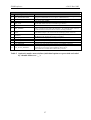
Due to the way the ELMB’s CAN-controller handles Remote Frames, it is recommended to disable Remote
Frames permanently if not needed (for PDO read-out). A special provision in the software has been made to ensure that the Node Guard Remote Frame is still handled properly.
26
ELMB software
Object 5C00: Compile Options
Bit Compile Option
0
ALL_MOTHERBOARDS
1
2
MOTHERBOARD1
–
3
ADC_AVR
4
ADC_NONE
5
7BIT_NODEID
6
RS232
7
ELMB103
8
9
10
11
12
VARS_IN_EEPROM
–
INCLUDE_TESTS
–
CAN_REFRESH
13
2313_SLAVE_PRESENT
v2.0 12-Nov-2003
Comment
assume ELMB is plugged on Motherboard v3; if this fails try assuming ELMB is
plugged on Motherboard v1/v2 (no option = Motherboard v3)
assume ELMB is plugged on Motherboard v1, v2 (no option = Motherboard v3)
(was option ADC_ELMB)
use the ATmega128 processor's integrated on-chip 8-chan 10-bit ADC, instead of
the ELMB's onboard 64-chan 16-bit ADC (type CS5523)
no ADC used
only DIP-switch 1 used for CAN baudrate (125 or 250 kbaud);
other 7 switches used for setting the Node-ID: 1-127 (when this option is not set
a 6-bit Node-ID is used and 2 bits are used for selecting a baudrate)
include stuff to be able to use 'printf()' and such; requires the Programmer or
other RS232 adapter to be connected to the ELMB programmer connector
the ELMB is an ELMB103 type (with ATmega103 processor); by default an
ELMB128 (with ATmega128 processor) is assumed
store/retrieve working copies of configuration parameters in/from EEPROM
(was option HEARTBEAT)
include an OD object through which (board) tests can be executed
(was option EEPROM_UINT16_ADDRESSES)
refresh CAN-controller descriptor register (at each buffer write/read)
there is (probably) a Slave processor (usually when using an ELMB103, so in
combination with compile option ELMB103 shown above);
this includes the code that deals with the Slave processor
Table 5. Optional compiler macro defines (individual options are preceeded and ended
by a double underscore '__').
27
ELMB software
v2.0 12-Nov-2003
Standardized Device Profile Area (according to CiA-DS4O1)
Index
(hex)
Sub
Index
Description
Data/
Object
Read state 8 Input lines
Number of 8-bit inputs
Read inputs 1-8
Read inputs 9-16
Array
U8
U8
U8
RO
RO
RO
2
6005
*
Global Digital Input Interrupt Enable
Bool
RW
0
6006
Array
0
1
2
Interrupt Mask Any
Change 8 input lines
Number of 8-bit inputs
Interrupt Mask Inputs 1-8
Interrupt Mask Inputs 9-16
U8
U8
U8
RO
RW
RW
2
FFh
FFh
0
1
2
Write state 8 Output lines
Number of 8-bit outputs
Write outputs 1-8
Write outputs 9-16
Array
U8
U8
U8
RO
RW
RW
2
0
1
2
Filter Mask 8 output lines
Number of 8-bit masks
Filter mask outputs 1-8
Filter mask outputs 9-16
Array
U8
U8
U8
RO
RO
RW
2
FFh
FFh
Record
0
Read Analogue Input
manufacturer-specific
Number of analog inputs
U8
RO
1
Input 1
I24
RO
2
…
…
64
Input 2
…
…
Input 64
I24
…
…
I24
RO
…
…
RO
0
Write Analogue Out 16-bit
Number of 16-bit outputs
Array
U8
RO
1
2
…
…
64
Output 1
Output 2
…
…
Output 64
U16
U16
…
…
U16
RW
RW
…
…
RW
6000
0
1
2
*
*
6200
6208
*
6404
6411
Attr
Default
Comment
ELMB PORTF
ELMB PORTA;
see Object 6208, 2
Enable/disable change-of-state
TPDO1 transmission
Only bits set to 1 will generate
a TPDO1 on change
28
ELMB PORTC
ELMB PORTA
64
16 or 64
PORTA pins not defined as outputs (maskbit=1) are inputs, to
be accessed thru Object 6000, 2
8 bits status, 16 bits analogue
value
Fixed, but actual hardware configuration may vary
(see OD index 2100, sub 1)
1st analog input:8-bit flags +16-bit
data
2nd "
"
"
"
…
…
64th "
"
"
"
=16 when MAX5122 DAC used,
=64 when MAX525 DAC used
(see OD index 2500)
1st analog output:16-bit
2nd analog output:16-bit
…
…
64th "
"
"
ELMB software
v2.0 12-Nov-2003
Standardized Device Profile Area (according to CiA-DS4O1)
Index
(hex)
Description
Data/
Object
Attr
Default
6423
*
Global Analog Input Interrupt Enable
Bool
RW
0
6424
Array
0
1
2
…
64
255
Analogue Input Interrupt
Upper Limit
Number of analog inputs
Input 1
Input 2
…
Input 64
All Inputs (1 to 64)
0
1
2
…
64
255
Analogue Input Interrupt
Lower Limit
Number of analog inputs
Input 1
Input 2
…
Input 64
All Inputs (1 to 64)
0
1
2
…
64
255
Analogue Input Interrupt
Delta Unsigned
Number of analog inputs
Input 1
Input 2
…
Input 64
All Inputs (1 to 64)
*
*
*
*
Sub
Index
6425
*
*
*
*
6426
*
*
*
*
U8
I32
I32
…
I32
I32
Enables/disables readout-onchange TPDO3 transmissions
(v4.2+)
RO
RW
RW
…
RW
WO
64
-1
-1
-1
-1
Array
U8
I32
I32
…
I32
I32
Comment
Voltage in µV (signed)
Voltage in µV (signed)
…
Voltage in µV (signed)
Voltage in µV (signed)
(v4.2+)
RO
RW
RW
…
RW
WO
64
0
0
RO
RW
RW
…
RW
WO
64
0
0
0
0
Voltage in µV (signed)
Voltage in µV (signed)
…
Voltage in µV (signed)
Voltage in µV (signed)
Array
U8
U32
U32
…
U32
U32
29
0
0
Voltage in µV (unsigned)
Voltage in µV (unsigned)
…
Voltage in µV (unsigned)
Voltage in µV (unsigned)
ELMB software
v2.0 12-Nov-2003
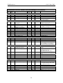
6 Emergency Objects
Emergency messages are triggered by the occurrence of an internal (fatal) error situation. An
emergency CAN-message has the following general syntax:
ELMB → Host
COB-ID
080h +
NodeID
Byte 0-1
Emergency
Error Code
Byte 2
Error Register
(Object 1001h)
Byte 3-7
Manufacturer specific error field
The following Emergency messages may be generated by the ELMBio application (note that
byte 2 containing the Error Register is not included in the table):
Error
Description
Emergency
Error Code
Manufacturer-Specific Error Field
(byte 3-7)
(byte 0-1)
CAN communication
8100h
Byte 3: 81C91 Interrupt Register content 1
Byte 4: 81C91 Mode/Status Register content 2
Byte 5: error counter
Byte 6: bus-off counter (see OD index 3200, sub 3)
Life Guarding
8130h
(CAN-controller has been reinitialized)
RPDO: too few bytes
8210h
Byte 3: minimum DLC (Data Length Code) required
ADC:
conversion timeout
5000h
ADC:
reset failed
5000h
ADC:
offset calibration failed
ADC:
gain calibration failed
ADC problem(s) during
initialisation
ADC calibration constants: not available
5000h
5000h
Byte 3: 01h
Byte 4: ADC channel number (0..63)
Byte 5: 0
Byte 3: 02h
Byte 4: 00h
Byte 5: Error id 3
Byte 3: 03h
Byte 4: 00h
Byte 3: 04h
Byte 4: 00h
Byte 3: 10h
Byte 4: ADC status (see OD index 1002)
Byte 3: 11h
Slave processor not responding (ELMB103
only)
5000h
Byte 3: 20h
5000h
5000h
…table continues on the next page…
1
2
3
81C91 INT register bits: 04h: Warning Level, 20h: Bus Off, 40h: Error Passive, 80h: Transmit Check
81C91 MODE/STATUS register bits: 01h: Init Mode, 02h: Reset State, 04h: Bus Off, 08h: Receive Error
Counter >= 96; 10h: Transmit Error Counter >= 96, 20h: last Transmission Complete, 40h: Receive Mode,
80h: Auto Decrement Address
01h: Reset-Valid bit not set, 02h: Reset-Valid bit not reset, 04h: error in Offset Register value,
08h: error in Gain Register value
30
ELMB software
Error
Description
1
2
3
4
v2.0 12-Nov-2003
Emergency
Error Code
Manufacturer-Specific Error Field
(byte 3-7)
(byte 0-1)
CRC error
5000h
Byte 3: 30h
Byte 4: 1 (program FLASH),
2 (Slave FLASH; ELMB103 only)
EEPROM: write error
5000h
EEPROM: read error
5000h
Byte 3: 41h
Byte 4: Parameter block index 1
Byte 5: = 0: while writing datablock info
> 0: size of parameter block to write
Byte 3: 42h
Byte 4: Parameter block index 1
Byte 5: Error id (1=CRC, 2=length, 4=infoblock)
EEPROM: ADC-limits
write error
5000h
Byte 3: 43h
Byte 4: Parameter block ID 2
Byte 5: size of parameter block to write
Irregular reset (Watchdog,
Brown-out or JTAG)
5000h
Byte 3: F0h
Byte 4: microcontroller MCUCSR register contents 3
Bootloader: not present
5000h
Byte 3: F1h
Bootloader is now in
control 4
5000h
Bootloader cannot jump to
application: invalid 4
6000h
Byte 3: FEh
Byte 4: 01h
Byte 5: 28h
Byte 6: microcontroller MCUCSR register contents 3
Byte 7: 00h
Byte 3: FEh
Byte 4: AAh
Byte 5: AAh
Byte 6: 00h
Byte 7: 00h
0: PDO communication parameters, 1: Guarding parameters, 2: ADC configuration, 3: Digital I/O configuration,
4: DAC configuration, 5: CAN configuration parameters,
FEh: Calibration constant(s), FFh: ELMB Serial Number.
1: ADC delta-change values, 2: ADC upper limits, 3: ADC lower limits
ATmega128 MCUCSR register bits: 01h: Power-On Reset, 02h: External Reset, 04h: Brown-Out Reset,
08h: Watchdog Reset, 10h: JTAG Reset, 80h: JTAG Interface Disable
The Emergency message is actually generated by the Bootloader program !
31
ELMB software
v2.0 12-Nov-2003
Byte 2 of the Emergency message contains the value of the socalled Error Register (Object
Dictionary index 1001h, a mandatory CANopen object). One or more bits of the 8-bit Error
Register can be set to 1, depending on the node's history of errors since the last reset. The table below gives a description of the meaning of the different bits.
Error Register (Object 1001h) bits
Bit
0
1
2
3
4
5
6
7
Error type
generic
current
voltage
temperature
communication
device profile specific
reserved (=0)
manufacturer specific
References
[1] CAN-in-Automation e.V.,
CANopen, Application Layer and Communication Profile,
CiA DS-301, Version 4.0, 16 June 1999,
http://www.can-cia.de
[2] H.Boterenbrood,
CANopen, high-level protocol for CAN-bus,
Version 3.0, NIKHEF, Amsterdam, 20 March 2000,
http://www.nikhef.nl/pub/departments/ct/po/doc/CANopen30.pdf
[3] 8-bit AVR Microcontroller with 128K Bytes In-System Programmable Flash,
ATmega128, ATmega128L,
ATMEL product datasheet.
http://www.atmel.com/atmel/products/prod23.htm
[4] SAE81C90/91, Standalone Full-CAN Controller,
SIEMENS product datasheet, preliminary, January 1997.
[5] CAN-in-Automation e.V.,
CANopen Device Profile for Generic I/O Modules,
CiA DS-401, Version 2.0, 20 December 1999,
http://www.can-cia.de
[6] CRYSTAL CS5521/22/23/24/28, 16-Bit or 24-bit, 2/4/8-Channel ADCs with
PGIA, CIRRUS LOGIC product datasheet, DS317F2, May 2000,
http://www.cirrus.com
32