1
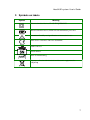
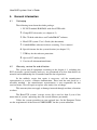
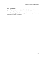
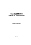
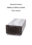
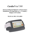
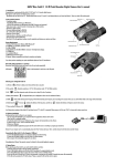
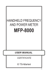
HeartVUE system
for non-invasive screening of heart
User’s Guide
Read Me First
Rev. 1
Pag
HeartVUE system. User’s Guide
Warnings
2
•
Use IEC60601-1-1 standard to combine the HeartVUE system with other
devices (computers and peripherals), see chapters 6.1 and 6.2.
•
Do not operate HeartVUE system within 3 meters of an operating cellular
phone, similar radio transmitting device, other powerful radio interference
producing sources such as arc welders, radio thermal treatment equipment,
x-ray machines, or any other equipment that produces electrical sparks (see
chapter 8.3).
•
Reusable electrodes present a potential risk of cross-infection especially when
are used on abraded skin, unless they are restricted to a single patient or
sterilized between patients. The sterilization recommendations from electrode
producer should be used.
•
Explosion Hazard. Do not use the HeartVUE system in the presence of a
flammable anesthetic mixture with air, or with oxygen or nitrous oxide.
•
Do not immerse the any parts of HeartVUE system in water.
•
Take care of the system’s components. Evoid the cables’ breaks, kinks,
tension and other mechanical efforts.
•
Take care of arranging Patient and USB cables/wires to avoid the risk of
patient entanglement or strangulation.
•
The operator is responsible to ensure the safety of any devices controlled or
triggered by any software or hardware receiving data from the HeartVUE
system. And this system must not be configured or connected in such a way
that failure in its data acquisition, processing or control functions can trigger
patient feedback stimulus that poses an unacceptable level of risk.
•
Use the special ECG electroconductive gel/paste for the ECG acquisition.
•
Do not spread the electroconductive gel/paste on wounded or scarred skin.
•
The HeartVUE system is intended for screening analysis of the ECG signals
only for adults. It is not suitable for children up to the age of 12 years old. The
system can be used for children and teenagers up to age 12-18 years old only
for monitoring the tendencies in dispersive parameter changes. For children
and teenagers the use of the system is determined by the doctor in each
specific case.
HeartVUE system. User’s Guide
•
The HeartVUE system does not diagnose! The system functions to define
earlier dispersive deviations in the heart boundary states and inform about the
presence of the pathology. The HeartVUE system is not a substitute the other
clinical methods of heart diagnostics; it gives the additional information about
the microchanges in the myocardium state.
•
The drug taking can influence on the accuracy of the heart portraits’
visualization and forming the conclusion and comments. If the system is used
during the drug treatment it is necessary to compare the current data with the
data collected before the drug taking.
3
HeartVUE system. User’s Guide
Manufacturer and representatives
The Manufacturer is Medical Computer Systems Ltd.
ADDRESS:
PHONE:
FAX:
E-MAIL:
INTERNET:
Passage 4922, 4-2, Zelenograd, Moscow, 124460, Russia
+7 495 913 31 94
+7 495 913 31 95
[email protected]
www.mks.ru
The European Representative is HeartView – Europe
ADDRESS:
PHONE:
FAX:
E-MAIL:
Talstrasse 20, CH-8001, Zurich, Switzerland
+41 1 212 60 06
+41 1 212 60 07
[email protected]
The World Representative is Heart View LLC
ADDRESS:
PHONE:
FAX:
E-MAIL:
6805 Mayfield Rd., Ste. 1203 Cleveland, OH 44124, USA
+1 440 829 55 90
+1 440 442 56 29
[email protected]
Document number: 3180.
The manufacturer has the right to alter this document according to the changes made
by manufacturer for improving the system.
Print errors which may be presented in this guide will be corrected in future editions.
4
HeartVUE system. User’s Guide
Contents
Warnings ........................................................................2
Manufacturer and representatives..................................4
Contents..........................................................................5
1. Abbreviations..............................................................6
2. Symbols on labels........................................................7
3. Main features...............................................................8
4. General information..................................................10
5. Installation..................................................................12
6. External components.................................................19
7. Malfunctions and their correction...............................21
8. Specifications.............................................................23
5
HeartVUE system. User’s Guide
1. Abbreviations
Term
CPU
Central processing unit
DC
Direct current
ECG
Electrocardiogramm
EMC
Electromagnetic compatibility
LED
Light emitting diode
MCS
Medical Computer Systems, Ltd
OS
Operational system
PC
Personal computer
RF
Radio frequency
USB
6
Meaning
Universal serial bus
HeartVUE system. User’s Guide
2. Symbols on labels
Symbol
Meaning
Electrical medical device, CLASS II EQUIPMENT.
Electrical medical device, TYPE CF with defibrillator protection.
Attention. Carefully read specification or instruction for use.
This device conforms to Directive 93/42/EEC.
USB connector.
Serial number.
Date of manufacturing.
Separate collection with electrical and electronic equipments for
recycling.
7
HeartVUE system. User’s Guide
3. Main features
3.1
Intended use
The HeartVUE is a computer system for easy and efficient non-invasive
screening of heart which provides a rapid 3-D colored image of heart by using 6
standard ECG leads (4 wires only from the patient's wrists and ankles).
This system contains the PC-ECG module KARDi2/4 and the CardioDM06® software that converts the electric conductivity of the cardiac tissue into a 3dimensional, color-coded image which is simple for physicians to interpret. The
basic operating principals of the CardioDM-06® software are described in the
“CardioDM-06® software for heart screening. User’s Manual”.
The HeartVUE system will prove to be an invaluable screening tool for
cardiologists, general practitioners, clinics, hospitals, the fitness industry, sports
teams and emergency medical facilities.
3.2
Basic Functionality
The basic features of the HeartVUE system are:
1.
the 30 or 60 second ECG acquisition of the 6 standard leads (I,
II, III, aVR, aVL, aVF) by KARDi2/4, analyzing and visualization;
2.
analyzing and creating the 3D colored image of heart (later the
heart portrait) where a state of the heart zones is displayed by colors;
3.
analyzing and showing the “Myocardium”, “Rhythm”, “Pulse”
and “Detailing” indices;
4.
the conclusion and comments creating.
Pic.1 The basic features’ diagram of the HeartVUE system.
8
HeartVUE system. User’s Guide
3.3
Classification
The HeartVUE system is а Class IIa device according to Council Directive
93/42/EEC for medical devices.
The system is classified for CLASS II TYPE CF EQUIPMENT according to
IEC 60601-1 (protection against electric shock).
The system classified by CISPR 11 standard as a Group 1, Class B
equipment according to IEC 60601-1-2 (electromagnetic compatibility). For more
information about EMC see chapter 8.3.
9
HeartVUE system. User’s Guide
4. General information
4.1
Packaging
The following items form the whole package:
1. PC-ECG module KARDi2/4 with fixed USB cable.
2. Clamp ECG electrodes (see chapter 6.3).
3. The CD disk with driver and CardioDM-06® software.
4. HeartVUE system. User’s Guide (this document).
5. CardioDM-06® software for heart screening. User’s manual.
6. Special fastener for the system fixation (see chapter 5.3).
7. USB key for the software protection.
8. Optional PC and/or printer.
9. Case for all aforementioned items.
4.2
Warranty, service life and utilization
The system and all equipment according to the chapter 4.1, excluding the
ECG electrodes, special fastener and case, are guaranteed to be free from defects in
material and workmanship for 24 months from the date of purchase.
In the unlikely events that repair is necessary, call the manufacturer
representative to receive a Return Authorization. Then send the unit back by a
traceable method – the manufacturer representative is not responsible for not
received items. We will repair or replace your unit(s) free of charge.
This warranty does not apply to damage incurred through accident, alteration
or abuse.
The HeartVUE systems’ average service life is not less than 5 years if the
mean time of system’s operating does not exceed 80 hours per month.
Utilize the system according to your regional laws. In the European Union
use the requirements of the Directive 2002/96/EEC for the system utilization.
10
HeartVUE system. User’s Guide
4.3
Maintenance
Regularly use surface disinfectants, but not less than one time in the month.
For material compatibility use the disinfectants based on the alcohol.
Factory testing and calibration ensure equipment accuracy and frequency
response during the whole system’s life cycle. If necessary, contact the manufacturer
representative for factory re-calibration.
11
HeartVUE system. User’s Guide
5. Installation
5.1
Hardware installation
Pic.2 The KARDi2/4 PC-ECG module:
left picture – the front side, right picture – the back side.
1. Unpack the package and check that all parts of the system according to the
chapter 4.1 have been received and are undamaged.
The face of PC-ECG KARDi2/4 module is showed on the left picture, the
back side is showed on the right one.
2. Fixate the KARDi2/4 PC-ECG module on the surface using the special fastener
(see chapter 5.3).
3. Turn on the PC and wait till the Windows OS will be loaded. Make sure that
the PC meets the requirements of the chapters 6.1 and 6.2.
4. Insert the CD disk with driver and CardioDM-06® software in the CD-ROM.
5. Plug the USB cable of the KARDi2/4 PC-ECG module, which has the USB
cable label, into the free USB port of the PC or of the USB hub with the
external power source. If it is for the first time, the driver installation procedure
will run automatically (refer to chapter 5.1.1).
12
HeartVUE system. User’s Guide
6. Install the CardioDM-06® application software (see chapter 5.2).
7. Plug the USB protection key, which has the HeartVUE-K label, into another
free USB socket of the PC. The key should be plugged in the computer’s
free USB socket ONLY if the installation of the CardioDM-06® software is
finished (also see chapter 3.3 of the CardioDM-06® software for heart
screening. User’s Manual).
8. Connect ECG electrodes to the ECG connectors (see chapter 6.3).
9. Read the “CardioDM-06® software for heart screening. User’s Manual”
document and use the CardioDM-06® software to operate with KARDi2/4.
10.Place the ECG electrodes to the patients’ wrists and ankles and start a new
examination.
5.1.1
Driver first time installation
After first connection KARDi2/4 to PC (see chapters 6.1 and 6.2.) by USB
cable, Windows will show the message Found new hardware and start the wizard
dialog Found New Hardware Wizard for new device installation.
The dialog windows for Windows XP OS are shown below. For other
version of Windows OS the dialog may be different.
1. When Windows asks to connect to Windows Update, select No, not this
time and the press Next button.
13
HeartVUE system. User’s Guide
2. Windows will ask to install software automatically or from specific
location. Select Install from a specific location and press Next.
3. Select Search for the best driver in these locations and check Include this
location in the search. Use Browse button to select directory where the driver’s files
are located (for example – D:\Driver) and press Next.
14
HeartVUE system. User’s Guide
4. Windows will show the installation progress for driver’s files within few
seconds. At the end of installation press Finish button.
5. To check that the driver installation was successful verify that in the
Device Manager the KARDiDSP appears under the MCS USB Medical Devices.
15
HeartVUE system. User’s Guide
5.1.2
Driver update
For updating the driver double-click on the KARDiDSP device in the
Device Manager. From the dialog select Driver property page and press the
Update Driver… button.
1. Alternatively, right-click on the KARDiDSP in the Device Manager and
then select Update Driver from the context menu.
2. Then follow the Hardware Update Wizard and perform the same steps as
during the first time installation. After getting to the following dialog select Don’t
search. I will choose the driver to install. Press Next button.
16
HeartVUE system. User’s Guide
3. Press the Have Disk…button.
4. Then select location of the driver’s files and press OK.
5. Then press Next button to start the installation process and wait till
the finish dialog will appear.
17
HeartVUE system. User’s Guide
5.2
Software installation and operation
The installation description of the CardioDM-06® software for heart
screening you can find in the applicable document “CardioDM-06® software for
heart screening. User’s Manual”. This document includes the operation
documentation too.
5.3
The PC-ECG module fixation
For fixating the KARDi2/4 PC-ECG module on the surface use the special
fastener which consists of continuous strips of plastic backing, with plastic
mushroom shaped stems protruding up from the backing strip.
The first part of the fastener you can find on the back side of the KARDi2/4.
The second part of the fastener is a substrate which can be found in the package.
The substrate has a protective liner. Remove the protective liner and press
firmly onto the substrate for full surface contact. All surfaces must be clean, dry, and
free of oil, grease, dust etc. The special fastener is disposable and permanent. Be
attentive at a choice of an attachment place of the fastener!
When two pieces of the fastener are pressed together, the mushroom heads
interlock with one another with an audible snap. To open, simply pull apart.
18
HeartVUE system. User’s Guide
6. External components
6.1
Safety with system
For connecting the HeartVUE system with other devices (computers and
peripherals – printers, scanner etc) use the IEC60601-1-1 standard about safety
requirements of medical electrical systems.
The system is typically used inside the PATIENT ENVIRONMENT (area
near 1.5 meters around the patient, see pic.3), that is why all the other devices used
with the system should be medical and meet the requirements of the IEC60601-1
standard (for example, PC Advantech POC-174).
Pic 3 Example of the PATIENT ENVIRONMENT
If non-medical devices are connected to the system via USB and if it is
inside the PATIENT ENVIRONMENT then:
1.
all devices have to be connected to the medical (IEC60601-1)
isolation transformer (transformers) with sufficient power supply (for
example, AEL Group MIT Medical Isolation Transformers) or
2.
all devices should be powered from internal energy sources.
However, the PC-ECG module has minimum 3 meters cable to PC with
USB connector fixation and touch protection construction. The isolation transformer
may not be used if the guaranteed minimal distance to any non-medical device,
which meet the requirements of the IEC60601-1-1 standards, will be more than 1.5
meters (outside PATIENT ENVIRONMENT).
19
HeartVUE system. User’s Guide
6.2
Computer and peripheral devices
Connected computer, as well as others peripheral devices, like printers, must
have
mark and comply with the safety standard for office machines (DIN VDE
0805 or EN60950 or IEC950 or any).
Computer must conform to minimal requirements:
• CPU with equivalent performance not less than Intel Celeron1000MHz.
• Run under Microsoft Windows XP OS.
• Has two free USB1.1 or compatible port.
The CardioDM-06® software uses the graphic standard DirectX for the
heart portraits’ visualization. Make sure that all the latest updates for the Windows
OS or its applications, and that the latest USB patches or drivers made by the PC’s
or system board’s developers, are installed on the PC.
6.3
ECG electrodes and electroconductive gels/pastes
For ECG acquisition the ECG electrodes must have the
mark and the
maximum polarization voltage less 300 mV should be used. These electrodes (or
wire to electrode) must have the 4 mm socket for connection. For example, the
FIAB F9024 (nickel-silver) or F9024SSC (nickel-silver chloride) clamp electrodes
may be used.
Other types of electrode connectors can be used by adapter (3 mm socket,
snap type, etc). For example, the FIAB PG922/4T snap adapter may be used for
disposable electrode connection.
The electroconductive gel/paste used for the ECG acquisition must have the
mark. For example, NUPREP EEG & ECG Skin Prepping Gel.
20
HeartVUE system. User’s Guide
7. Malfunctions and their correction
The possible malfunctions and actions for their correcting are in the
following table.
Malfunction
Probable reason
The CD disk cannot be read The CD disk became dusty.
by the CD-ROM.
Corrective actions
Extract the CD disk from the CDROM and carefully clean the dick
with the cleaning based on the
alcohol.
If the malfunction is not corrected
contact the manufacturer
representative.
The New examination
button
is not active.
The PC-ECG module is not
plugged to the PC.
The driver is not installed.
Check the USB cable connection.
Make sure that the PC-ECG
module KARDi2/4 is plugged into
the USB hub with the external
source of power.
Install the driver (see chapter
5.1.1). If the driver is installed update it (see chapter 5.1.2).
Restart the program.
The indicator “Mode” is
red.
The error occurred.
Replug the PC-ECG module.
Reinstall the system driver.
If the malfunction is not corrected
contact the manufacturer
representative.
The MCS USB Medical
Devices is not appeared in
the Computer management.
The KARDiDSP is not
displayed in the Device
Manager under the MCS
USB Medical Devices.
The connection between PC Check the connection between PC
and PC-ECG module
and PC-ECG module, or
failure.
replug the PC-ECG module.
The system driver is not
installed.
Install the system driver.
The heart portraits have a
black line.
The fonts or buttons of the
CardioDM-06® software’s
interface are changed.
The video drivers are not
updated.
Update the video drivers.
If the malfunction is not corrected
contact the manufacturer
representative.
21
HeartVUE system. User’s Guide
Malfunction
The screening analysis
takes more time than 1
minute.
Probable reason
The CardioDM-06®
software has been run with
the concurrently running
programs (especially with
the antivirus monitors).
Corrective actions
Close the other running programs,
especially the antivirus monitors.
All (or one) of the ECG
The electrodes (or the
Check the electrode cable’s
signals are not displayed on electrode of this lead) are
connection. Check the electrode
the screen.
not connected to the patient. cable’s fixation in the electrode.
PC-ECG module failure.
Check the connection between the
electrode and the patient.
If the malfunction is not corrected
contact the manufacturer
representative.
All (or one) of the ECG
signals are very noisy.
The electrodes (or one
electrode) are not greased
with the electroconductive
paste/gel.
Grease the electrodes (or one
needed electrode) with the
electroconductive paste/gel.
Operate the system in the
prescribed conditions.
Read the Warning about
conditions of system’s operating.
22
HeartVUE system. User’s Guide
8. Specifications
8.1
Main functions
Function
Value
ECG acquisition
The ECG acquisition of the 6 standard leads (I, II, III,
aVR,aVL, aVF) by KARDi2/4 PC-ECG module.
Heart portrait
The heart portrait is “a snap shot” on display as a result of
calculating mean dispersion characteristics of low-amplitude
fluctuations during ECG input.
“Myocardium” indicator
The “Myocardium” indicator is relative characteristics,
which describe the total value of dispersion deviations and
range from 0% to 100%.
“Rhythm” indicator
The “Rhythm” describes the changes in the R–R intervals
variability characteristics in range from 0% to 100%.
“Pulse” indicator
The “Pulse” shows the quantity of the heartbeats in a minute
defining bradycardia, tachycardia or normal condition.
“Detailing” indicator
The “Detailing” describes the heart condition using the
analysis of the described above indices.
8.2
KARDi2/4 PC-ECG module
Parameter
Value
Number of channels
The HeartVUE system has 3 monopolar channels.
The ECG leads are calculated on the PC by CardioDM06® software
Analog front end
DC amplifiers
Input range (effective resolution
for 500Hz output data rate)
±410 mV (2 uV)
Defibrillator protection
on base semi-conductors elements
Input DC impedance
greater 70 MOhm according to N electrode
Check electrode connection
Checking connection during registration by measure of
DC offset
Analog-to-digital conversion
Sigma-delta modulation with frequency 2048kHz
simultaneously on all channels, a digital filtration and
23
HeartVUE system. User’s Guide
Parameter
Value
decimation up to frequency 16kHz
Digital signal processing
Filtration and decimation up to 500 Hz output data rate
(20-bit resolution). Internal low pass filters has the -3
dB level on 150 Hz and 5% level on 100 Hz
accordingly
Connectors type for electrode
4 mm banana jacks
Galvanic isolation
Reinforced according to IEC60601-1 from PC side
Power line
USB
Voltage
+5 V ± 10%
Maximal current in active mode
less 280 mA
Computer Interface
USB1.1, full speed mode, plug-and-play support
Status indicators and modes
Bi-color LEDs indication:
•
green – no error, active mode. The indicator is
burning green during the new examination’s
making
•
red – error occurred
USB cable
Min length 3 m, fixed to module
Electrode cable’s length
not less than 140 cm
Dimensions of enclosure
100x65x28 mm
Weight with cables
less 350 gram
Working temperature
+10ºC…+35ºC
Storage temperature
+5ºC...+40ºC
Transportation temperature
-30ºC...+50ºC
Humidity
up to 97% without condensation
Mechanical resistance
According to IEC 60601-1
24
HeartVUE system. User’s Guide
8.3
Electromagnetic compatibility
Guidance and manufacturer’s declaration – electromagnetic emissions
The HeartVUE system is intended for use in the electromagnetic environment specified below.
The customer or user of the system should assure that it is used in such an environment.
Emission test
Compliance
Electromagnetic environment – guidance
RF emissions
Group 1
The system uses RF energy only for its internal
function. Therefore, its RF emissions are very low
and are not likely to cause any interference in
nearby electronic equipment.
Class B
The system is suitable for use in all establishments
other than domestic and those directly connected to
the public low-voltage power supply network that
supplies buildings used for domestic purposes.
CISPR 11
RF emissions
CISPR 11
Harmonic
emissions
Not applicable
IEC 61000-3-2
Voltage
fluctuations/
flicker emissions
Not applicable
IEC 61000-3-3
Electrostatic
discharge (ESD)
±6 kV contact
±6 kV contact
IEC 61000-4-2
±8 kV air
±8 kV air
Electrical fast
transient/burst
±2 kV for power
supply lines
Not applicable
±1 kV for
input/output lines
±1 kV for
input/output
lines
Floors should be wood,
concrete or ceramic tile. If
floors are covered with
synthetic material, the relative
humidity should be at least 30
%.
IEC 61000-4-4
25
HeartVUE system. User’s Guide
Guidance and manufacturer’s declaration – electromagnetic emissions
Emission test
Compliance
Electromagnetic environment – guidance
Surge
±1 kV
differential mode
Not applicable
±2 kV common
mode
Not applicable
Interruptions and
voltage variations
on power supply
input lines
<5% UT (>95%
dip in UT) for
0,5 cycle
Not applicable
IEC 61000-4-11
40% UT (60%
dip in UT) for
5 cycles
Not applicable
70% UT (30%
dip in UT) for 25
cycles
Not applicable
<5% UT (>95%
dip in UT) for
5 sec
Not applicable
3 A/m
3 A/m
IEC 61000-4-5
Power frequency
(50/60 Hz)
magnetic field
IEC 61000-4-8
26
Power frequency magnetic
fields should be at levels
characteristic of a typical
location in a typical commercial
or hospital environment.
HeartVUE system. User’s Guide
Immunity test
IEC 60601
test level
Compliance
level
Recommended separation
distance
Portable and mobile RF communications equipment should be used no closer to any part of the
system, including cables, than the recommended separation distance calculated from the
equation applicable to the frequency of the transmitter.
Conducted RF IEC
61000-4-6
3 Vrms 150kHz to
80MHz
Radiated RF IEC
61000-4-3
3 V/m 80MHz to
2,5GHz
3 Vrms
3 V/m
d = 1.17 P
d = 1.17 P 80 MHz to 800
MHz
d = 2.33 P
800 MHz to
2,5 GHz
Where P is the maximum output power rating of the transmitter in watts (W) according to the
transmitter manufacturer and d is the recommended separation distance in meters (m).
Field strengths from fixed RF transmitters, as determined by an electromagnetic site survey,a
should be less than the compliance level in each frequency range.b
Interference may occur in the vicinity of equipment marked with the
following symbol:
NOTE 1 At 80 MHz and 800 MHz, the higher frequency range applies.
NOTE 2 These guidelines may not apply in all situations. Electromagnetic propagation is
affected by absorption and reflection from structures, objects and people.
a
Field strengths from fixed transmitters, such as base stations for radio (cellular/cordless)
telephones and land mobile radios, amateur radio, AM and FM radio broadcast and TV
broadcast cannot be predicted theoretically with accuracy. To assess the electromagnetic
environment due to fixed RF transmitters, an electromagnetic site survey should be
considered. If the measured field strength in the location in which the system is used exceeds
the applicable RF compliance level above, the system should be observed to verify normal
operation. If abnormal performance is observed, additional measures may be necessary, such
as reorienting or relocating the system.
b
Over the frequency range 150 kHz to 80 MHz, field strengths should be less than 3 V/m.
27