1
™ Installation & Operation Manual Contact Information Corporate Head Office 267 Boston Road , Unit 11 Billerica, MA, 01862, USA Phone: +1 978 715 1020 Fax: +1 978 262 0179 International: +65 9006 1497 E-mail: [email protected] Website: www.echolab.com Office Hours: Monday - Friday 8AM - 5PM Local Time Support Hotline: +1 978 715 1030 (24 Hours, 7 Days) Support E-mail: [email protected] Disclaimer Notice to User Copyright 2009 Echolab Inc. All rights reserved. This manual or the software described herein, in whole or in part, may not be reproduced, translated, or reduced to any machine-readable form without prior written approval from Echolab Inc. Echolab Inc. Provides no warranty with regards to this manual, the software or other information contained herein and hereby expressly disclaims any implied warranties of merchantability or fitness for any particular purpose with regard to this manual, the software or such other information. In no event shall Echolab Inc. be liable for and incidental, consequential or special damages, whether based on tort, contract, or otherwise, arising out of or in connection with this manual, the software or other information contained herein or the use thereof. Echolab Inc. reserves the right to make any modification to this manual or the information contained herein at any time without notice. The software described herein may also be governed by the terms of a separate user license agreement. Warranty Echolab, Inc. warrants it’s switcher products will be free from defects in materials and workmanship for a period of 3 years from the date of purchase. Other accessory products supplied by Echolab will be free from defects in materials and workmanship for a period of 1 year from the date of purchase. If a product proves to be defective during this warranty period, Echolab, INC. will, at their discretion, repair or provide a replacement in exchange for the defective product. In order to obtain service under this warranty, you the Customer, must notify Echolab, INC. of the defect before the expiration of the warranty period and make suitable arrangements for the performance of service. Echolab, INC. shall pay for the delivery of the replacement product to the Customer if the shipment is to a location within the country in which an Echolab, INC. service center is located. The Customer shall be responsible for paying all shipping charges, insurance, duties, taxes, and any other charges for products returned to any other locations. Upon receipt of replacement product, the Customer shall be responsible for packaging and shipping the defective product to a designated service center nominated by Echolab, INC. with shipping charges prepaid. This warranty shall not apply to any defect, failure or damage caused by improper or inadequate maintenance and care. Echolab, INC. shall not be obligated to perform service under this warranty a) to repair damage resulting from attempts by personnel other than Echolab, INC. representatives to install, repair, or service the product, b) to repair damage resulting from improper use or connection to incompatible equipment, c) to repair any damage or malfunction caused by the use of non-Echolab, INC. parts or supplies, or d) to service a product that has been modified or integrated with other products when the effect of such a modification or integration increases the time or difficulty of servicing the product. THIS WARRANTY IS GIVEN BY ECHOLAB, INC. IN LIEU OF ANY OTHER WARRANTIES, EXPRESSED OR IMPLIED. ECHOLAB, INC. AND ITS VENDORS DISCLAIM ANY IMPLIED WARRANTIES OF MERCHANTABILITY OR FITNESS FOR A PARTICULAR PURPOSE. ECHOLAB, INC.’S RESPONSIBILITY TO REPAIR OR REPLACE DEFECTIVE PRODUcTs IS THE WHOLE AND EXCLUSIVE REMEDY PROVIDED TO THE CUSTOMER FOR ANY INDIRECT, SPECIAL, INCIDENTAL OR CONSEQUENTIAL DAMAGES IRRESPECTIVE OF WHETHER ECHOLAB, INC. OR THE VENDOR HAS ADVANCE NOTICE OF THE POSSIBILITY OF SUCH DAMAGES. Procedure for returning goods No returned goods, for service or otherwise, will be accepted without prior authorization from Echolab. To obtain return authorization, call Echolab Customer Support at +1.978.715.1030 or email [email protected]. Once approved, Echolab will supply you with your Returned Authorization (RA) number. Echolab cannot be responsible for units returned without an RA number. Echolab will advise you of the shipping address. The packaging must indicate the RA number on the outside of the packing. A copy of the RA which states the serial number of the items you’re returning must be included with the returned merchandise. This will speed up processing. Any units received without prior approval by Echolab will be returned to you freight collect. You shall be responsible for the cost of consolidated freight (one way only) for warranty units from your location to the location designated by Echolab. Once repaired, Echolab will incur the cost of UPS GROUND consolidated freight for warranty units to your location. Declaration of Conformity for CE Marking We Echolab, Inc. 267 Boston Road, Suite 11 Billerica, MA USA 01862 Contact Person: Ankit Patel Tel: 978-715-1029 Fax: 978-262-0179 E-mail: [email protected] Hereby declare that Products: Opera, Nova, Identity, Classic, Overture, RemoteAux Trade Name: Echolab Model Number: Opera 16 and 32 Chassis, Nova 16 and 32 chassis, Identity 4 Panel, Classic 7 and 9 Panels, Overture 1 Panel, Overture 2 Panel, OvertureMD Chassis, RA32 Are in compliance with the essential requirements and other relevant provisions of the following EC directives: Reference No. TITLE 89/336/EEC Electromagnetic Compatibility (EMC Directive) 73/23/EEC Low Voltage Directive (LVD) In accordance with Council Directive 93/68/EEC the product specified above was tested conformant to the applicable Rules of EN550022 for Class A equipment, and that all the necessary steps have been taken and are in force to assure that production units of the same product model will continue to comply with the requirements. Ankit Patel Product Manager Echolab, Inc. To disconnect the power, find the MAINS switch on lower right of the back side of the switcher chassis. Switch will connect or disconnect both ends of power. Caution - Do not expose to dripping or splashing. No objects filled with liquids, such as vases, may be placed on the apparatus. Must be connected to MAINS socket outlet with protective earthing connection. CE Compliant - The letters ‘CE’ are an abbreviation of Conformité Européenne, French for European conformity. Electric shock warning - ISO 3864, Number 5036 C-Tick Certified - EMC regulations in Australia and New Zealand (Pending) Table of Contents Introduction 1 Atem System Includes��������������������������������������������������������������������������������� 2 Atem Standard Features������������������������������������������������������������������������������ 2 Atem Optional Features������������������������������������������������������������������������������� 4 Conventions Used In This Manual��������������������������������������������������������������� 5 Atem Installation 7 Control Panel Connections�������������������������������������������������������������������������� 8 Power����������������������������������������������������������������������������������������������������������� 8 Mode Switch������������������������������������������������������������������������������������������������ 8 Video Standard and Genlock����������������������������������������������������������������������� 8 Inputs����������������������������������������������������������������������������������������������������������� 9 Configuring Inputs������������������������������������������������������������������������������������� 11 Frame Synchronization������������������������������������������������������������������������������ 12 Outputs������������������������������������������������������������������������������������������������������ 12 Configuring Outputs����������������������������������������������������������������������������������� 13 Multiviewer������������������������������������������������������������������������������������������������� 15 Saving Configuration���������������������������������������������������������������������������������� 16 Master Reset��������������������������������������������������������������������������������������������� 16 Input Tallies������������������������������������������������������������������������������������������������ 16 GPIO Connections������������������������������������������������������������������������������������� 17 RS422 Devices������������������������������������������������������������������������������������������ 17 Ethernet����������������������������������������������������������������������������������������������������� 19 Test Ethernet Communication�������������������������������������������������������������������� 20 Web Configuration������������������������������������������������������������������������������������� 21 Installing PC Tools������������������������������������������������������������������������������������� 22 Setup Menu����������������������������������������������������������������������������������������������� 23 Auxiliary Outputs 27 Customizing Auxiliary Routing ������������������������������������������������������������������ 28 Customizing Aux Labels���������������������������������������������������������������������������� 29 Saving output Routing������������������������������������������������������������������������������� 29 Restoring output Routing��������������������������������������������������������������������������� 30 Multiviewer Configuration 31 Default Multiviewer Routing����������������������������������������������������������������������� 32 Multiviewer Sources����������������������������������������������������������������������������������� 32 Customizing Multiviewer Routing �������������������������������������������������������������� 33 Customizing Multiviewer Labels���������������������������������������������������������������� 33 Saving Multiviewer Settings����������������������������������������������������������������������� 34 Restoring Multiviewer Settings������������������������������������������������������������������� 35 vii Panel Overview 37 Program & Preview Bus����������������������������������������������������������������������������� 38 Destination Display & Select Bus�������������������������������������������������������������� 39 Transition Control��������������������������������������������������������������������������������������� 39 Next Transition������������������������������������������������������������������������������������������� 40 Downstream Keyers & Fade To Black�������������������������������������������������������� 40 Universal System Control��������������������������������������������������������������������������� 41 Joystick, Number Pad, & System Status���������������������������������������������������� 41 Background Transitions 43 Cut Transitions������������������������������������������������������������������������������������������� 44 Auto Transitions������������������������������������������������������������������������������������������ 44 Manual Transitions������������������������������������������������������������������������������������� 45 Preview Transition�������������������������������������������������������������������������������������� 45 Transition Types����������������������������������������������������������������������������������������� 46 Saving and Recalling Transition Settings��������������������������������������������������� 49 Basic Keying 51 What is a Self Key (Luma Key)������������������������������������������������������������������ 52 What is a Linear Key���������������������������������������������������������������������������������� 52 What is a Shaped Key (Pre-Multiplied)������������������������������������������������������ 53 Setting a Upstream Keyer�������������������������������������������������������������������������� 53 Setting a Downstream Keyer��������������������������������������������������������������������� 53 Masking����������������������������������������������������������������������������������������������������� 54 Keyer Transitions 55 Downstream Keyer Transitions������������������������������������������������������������������� 56 Upstream Keyer Transitions����������������������������������������������������������������������� 56 Transition Examples����������������������������������������������������������������������������������� 57 Graphic Wipe 59 Performing a Graphic Wipe Transition�������������������������������������������������������� 60 Graphic Wipe Images�������������������������������������������������������������������������������� 61 Stinger Transitions 63 Performing a Stinger Transition������������������������������������������������������������������ 64 Configuring Stinger Settings���������������������������������������������������������������������� 64 Saving and Recalling Stinger Settings������������������������������������������������������� 67 SuperSource 69 Video Signal Flow Through SuperSource�������������������������������������������������� 70 Suggested Workflow���������������������������������������������������������������������������������� 70 Building SuperSource�������������������������������������������������������������������������������� 70 SuperSource Box Settings������������������������������������������������������������������������� 72 The Border Menu��������������������������������������������������������������������������������������� 72 viii Advanced Keying 73 Understanding Chroma Key����������������������������������������������������������������������� 74 Setting Up a Chroma Key�������������������������������������������������������������������������� 74 Understanding Pattern Key������������������������������������������������������������������������ 75 Setting Up a Pattern Key���������������������������������������������������������������������������� 76 Understanding DVE Keys��������������������������������������������������������������������������� 77 Setting Up a DVE Key�������������������������������������������������������������������������������� 78 Move Menu 79 Accessing Move Menu������������������������������������������������������������������������������� 80 Building Custom Move������������������������������������������������������������������������������� 80 Save/Recall DVE Keyframes���������������������������������������������������������������������� 81 Move Objects On Screen��������������������������������������������������������������������������� 81 Key Memory 85 Save Key Settings To Memory������������������������������������������������������������������� 86 Remove Key Settings From Memory��������������������������������������������������������� 86 Global On/Off��������������������������������������������������������������������������������������������� 86 Save Key Settings To Non Volatile Storage������������������������������������������������ 86 Recall Key Settings During Production������������������������������������������������������ 87 Media Players 89 Understanding Media Player Cross Points������������������������������������������������ 90 Understanding Media Player Memory������������������������������������������������������� 90 File Formats����������������������������������������������������������������������������������������������� 91 The Graphics Utility����������������������������������������������������������������������������������� 91 Loading Stills��������������������������������������������������������������������������������������������� 92 Loading Clips��������������������������������������������������������������������������������������������� 93 Displaying Stills������������������������������������������������������������������������������������������ 94 Playing Clips���������������������������������������������������������������������������������������������� 94 Capturing Stills������������������������������������������������������������������������������������������� 95 Saving Stills to the CF Card����������������������������������������������������������������������� 95 Saving Stills on a Computer����������������������������������������������������������������������� 96 DVE Borders 99 Accessing Border Menu��������������������������������������������������������������������������� 100 Border Styles������������������������������������������������������������������������������������������� 100 Border Parameters����������������������������������������������������������������������������������� 100 Sharing DVE Resources 103 Allocate DVE Resources For Transitions�������������������������������������������������� 104 Allocate DVE Resources For Keyers�������������������������������������������������������� 104 Color Generators 107 Adjusting Colors��������������������������������������������������������������������������������������� 108 Save/Recall Colors����������������������������������������������������������������������������������� 108 ix Macros 111 Why Do You Need Macros?����������������������������������������������������������������������112 Macro Editor Interface�������������������������������������������������������������������������������112 Recording Macro���������������������������������������������������������������������������������������113 Customizing Macro Button������������������������������������������������������������������������114 Save Macro�����������������������������������������������������������������������������������������������114 Load/Execute Macros�������������������������������������������������������������������������������115 Clear Macro Button�����������������������������������������������������������������������������������116 Command Reference��������������������������������������������������������������������������������117 The Compact Flash Card 119 Important Notes��������������������������������������������������������������������������������������� 120 Accessing Card���������������������������������������������������������������������������������������� 120 Folder Structure��������������������������������������������������������������������������������������� 121 Formatting Card��������������������������������������������������������������������������������������� 123 Configure Remote AUX 125 Change Remote Aux Panel IP Address��������������������������������������������������� 126 Configure Switcher����������������������������������������������������������������������������������� 129 Advanced Configuration��������������������������������������������������������������������������� 129 Hexadecimal Conversion Table���������������������������������������������������������������� 135 Compix CG Interface 137 Configuring Compix CG��������������������������������������������������������������������������� 138 Configuring Switcher�������������������������������������������������������������������������������� 138 Configuring Conductor����������������������������������������������������������������������������� 138 Compix CG Interface (Control Panel)������������������������������������������������������ 139 Compix CG Interface (Conductor)����������������������������������������������������������� 139 Compix Commands��������������������������������������������������������������������������������� 140 Shaped Keys Using Adobe Photoshop 141 Photoshop Settings���������������������������������������������������������������������������������� 142 Building Key��������������������������������������������������������������������������������������������� 142 Firmware Updates 145 Important Notes��������������������������������������������������������������������������������������� 146 You Will Need������������������������������������������������������������������������������������������� 146 Backup Current Configuration������������������������������������������������������������������ 146 Update Firmware������������������������������������������������������������������������������������� 147 Upgrading Echolab Software Tools���������������������������������������������������������� 147 x 1 Introduction Thank you for using the Echolab Atem. This manual provides step-by-step instructions on the installation and operation of the Echolab switcher. This manual should address any questions you may have so please be sure to read through these instructions prior to calling technical support. The following chapter will help you familiarize yourself with the Atem switcher and explain the conventions used in this manual. Introduction Atem System Includes Atem 3RU Chassis with Standard Power Supply Overture1 1M/E Switcher Control Panel This User Manual Atem Software CD 3 Year Full Warranty Parts/Labor at the Factory / Technical Support Power cables included for USA Only Atem Standard Features 10 Multiformat inputs Atem comes standard with 8 SDI inputs and 2 Analog/HDMI inputs. Atem was designed to support the current 3Gbps HD standard, meaning operators can produce images in the highest resolution possible today or be ready for it tomorrow. A scaler on every input allows the Atem to accept a mix of standard definition and high definition signals. Standard definition signals are up converted to high definition and high definition signals are cross converted to match the switcher’s operating format. Atem can input any analog, digital or computer signal. Analog signals can be Composite (CVBS), S-Video (Y/C), RGsB, or Component (YPbPr). Digital signals can be SD-SDI or HD-SDI. A wide range of computer resolutions are also supported via HDMI. (HDMI not HDCP compliant) Internal frame synchronizers Internal Frame Synchronizers allow wild feeds to be connected directly to the switcher. These “wild” feeds are input sources that are not timed or genlocked. Depending on the environment, they can be from live remotes, satellite feeds, distant cameras, BluRay players, DVD players, Computer outputs or last minute additions. Frame Synchronizers allow you to “lock” these inputs to the switcher. Frame synchronizers are standard on EVERY input of the Atem system. 6 Native Outputs Atem has a total of 8 outputs, 6 in the switcher’s operating format and 2 multiformat outputs. The native outputs include 2 HD-SDI program outputs, 1 HD-SDI preview output and 3 HDSDI auxiliary output that is fully routable. 2 Introduction 2 Multiformat outputs Atem has a total of 8 outputs, 6 in the switcher’s operating format and 2 multiformat outputs. The multiformat outputs include 1 Analog/HDMI auxiliary output that is fully routable and can output standard definition (CVBS, Y/C, YPbPr) as well as any high definition format (YPbPr and HDMI). 1 Analog/Digital auxiliary output that is fully routable and can output standard definition (SD-SDI, CVBS, Y/C, YPbPr) as well as any high definition format (YPbPr, HD-SDI). SuperSource Crosspoint Atem includes Echolab’s unique and invaluable SuperSource™ with four picture-in-picture generators. Ideal for multi box compositions - SuperSource™ allows the operator to pre-build sophisticated compositions that can be taken to air simply by pressing the SuperSource™ crosspoint and does not require the use of M/E keyers. The SuperSource™ includes four of its own keyers leaving upstream and downstream keyers available for adding lower thirds, tickers and other elements. 4 M/E Keyers The Atem includes 4 upstream or M/E keyers each includes a powerful Luma keyer, Pattern keyer, and Chroma keyer. The M/E keyers can also take advantage of the built in 2D DVE to create over the shoulder compositions. 2 Downstream Keyers The Atem includes 2 downstream keyers which are accessible from a dedicated DSK block. A DSK “Tie/Preview” button enables you to configure the key, tie it to the transition block, then take it to air with the next transition. The can also be taken immediately to air using the cut and auto buttons in the DSK block. 32 Live Image Buffers Atem includes 32 live image buffers, each with FILL + KEY, that can be used to load and play still images with alpha. For certain applications these image buffers eliminates the need for a dedicated still store. 2D DVE with 3D Borders and Drop Shadow Atem includes an advanced 2D DVE as standard. The DVE is available in the upstream keyers and includes sophisticated 3D borders and drop shadows, it can also be used to animate or reposition keys on screen. In the transition block it provides compelling program transitions such as pushes, squeezes and moves. 3 Introduction Atem Optional Features Remote Aux Panel The Atem has five routable outputs that can be controlled from the optional Remote Auxiliary panel. The Remote Aux communicates with the switcher via Ethernet and a maximum of four Remote Aux panels may be connected to the Atem switcher. Conductor Software The optional Conductor software is a PC based application that can be used to manage and launch macros, load graphics into the switcher’s frame buffer or frame store, route auxiliary outputs, and control various 3rd party devices. Conductor Touch Screen Computer The Conductor software is installed on a high quality touch screen PC and is then configured and tested with the Atem switcher. The Conductor software was designed for touch screen operation so this touch screen PC provides the most natural workflow. The Conductor software is used to manage and launch macros, loads graphics into the Switcher’s frame buffer or frame store, route auxiliary outputs, and controls various 3rd party devices. Redundant Power The Atem switcher chassis and panel can be built with additional power modules to provide full redundancy. The additional power modules require special caballing which can only be installed at the factory. This option must be ordered with the switcher and cannot be added after sale. Clip Player with Audio The optional clip player can be used for playing animated lower thirds with key channel, animated backgrounds or short clips such as show openers, show closings, and bumpers. The clip player is also integrated into the Atem Stinger™ transition. Integrated audio support allows you to add impact to your transitions and your overall production. 10 Channel Multiviewer Atem makes monitoring your production simple and inexpensive. Atem features a dedicated connection that outputs a ten channel multiviewer. Simply connect the multiviewer output to an inexpensive HDMI or DVI display to monitor program, preview and up to eight sources. 4 Introduction Conventions Used In This Manual There are several styles and layouts used in this manual to help the reader differentiate between differing types of information. Below are examples of these styles, and an explanation of each. WARNING: Cautions the user when the surrounding text discusses something that might result in production mistakes or corrupt switcher operation if not understood correctly. IMPORTANT: Provides insight into the inner workings of the Echolab switcher. This knowledge will help you understand how the switcher operates and ultimately help you get the most from your production switcher. Tips: Provide helpful suggestions on how to get the most from your production switcher Important Words are bold. 1. Steps are presented in this style. Notes made to Images and Figures are presented in this Style 5 Introduction 6 2 Atem Installation The Echolab Atem consists of two parts, a 3RU chassis that can be installed into a standard rack, and a 1 M/E control panel. The following chapter explains how to connect the system, including any optional items you may have purchased, and how to configure a computer to communicate with the switcher. Atem Installation Control Panel Connections The Atem system is connected to the panel using two 75-Ohm coaxial cables. The maximum length of separation is 300 meters. The following image displays how to connect the panel to the chassis. TX TX CONTROL PANEL RX RX Chassis Overture1 Panel Power Both the Atem chassis and control panel have a 3-pin shroud power connector that accepts 110-220 VAC 50/60 Hz power. Connect the provided universal power cord (provided in North America only) to a standard three prong power outlet. Both the Atem chassis and control panel ship with one internal power supply each. If ordered an additional power supply is installed at the factory for a redundant system. The chassis and panel automatically load balance across the supplies. Mode Switch The Mode switch allows the switcher to be configured and operated in up to 8 different modes. By default, the Mode switch should be set to 0 for initial start-up. Video Standard and Genlock Atem can accept analog blackburst or be set to internal genlock. Analog blackburst is the default genlock type for the system. The system status lights provide information regarding the state of the genlock signal and the switchers internal clock. 8 A On when the switcher is locked to the analog genlock source. Off if when switcher is operating in internal genlock. B On when the switcher finds an analog genlock source. Off if when switcher is operating in internal genlock. C Should always be on, similar to D indicates that the internal clock generated by the switcher is functioning correctly. D Should always be on and indicates that the internal clock that drives the switcher hardware is locked. Atem Installation The genlock type depends on the video standard of the switcher. The valid combinations of video standard and genlock type are listed in the table below. Video Standard Valid Analog Genlock 720p/50 Blackburst / PAL 720p/59.94 Blackburst / NTSC 1080i/50 Blackburst / PAL 1080i/59.94 Blackburst / NTSC Table of valid analog genlock signal depending on the switcher video standard. Internal genlock is valid for all video standards. The genlock type and video standard can be changed from the switcher control panel after the switcher is powered on. These settings are available in the video section of the setup menu. The menu also displays genlock statistics which can be used by Echolab engineering to find genlock faults. 1. Use the universal system HOME>SETUP>VIDEO. control to navigate to the video menu, 2. Use the first knob to change the video standard of the switcher. An asterisks (*) next to the video standard indicates that it is not the current format. 3. Use the last knob to change the genlock type. An asterisks (*) next to the genlock type indicates that it is not the current type. 4. Press the update button to SAVE the settings. Changing the genlock settings requires a reboot. The switcher will navigate to the boot menu. 5. Press the reboot button. 6. Press yes to confirm the reboot and the switcher will restart into the new video standard with the specified genlock type. Inputs The Atem has 10 up/cross converting inputs that can accept a variety of signals when the switcher is operating in high definition as long as the input frame rate matches the switchers operating frame rate. The inputs also support internal frame synchronization which can be manually enabled for inputs that match the switcher’s operating video standard or is automatically enabled for inputs that do not match the switcher’s operating format. 9 Atem Installation Inputs 1-4 and 6-9 are digital only inputs and accept standard definition NTSC or PAL signals over an SD-SDI connection and high definition 720p, 1080i and 1080p signals over an HD-SDI connection. Inputs 5 and 10 are “universal” inputs that accept analog, digital (HDMI), and computer (HDMI) signals. Standard definition signals can be Composite (CVBS), S-Video (Y/C), or Component (YPbPr). Analog high definition 720p, 1080i signals can be Componet (YPbPr). Digital high definition 720p, 1080i, 1080p and computer signals can be HDMI. Tip: The HDMI connector does not have any fasteners, it is therefore recommended that you fasten the HDMI cable to a nearby SDI cable to secure the connection. Component [3 BNC] (Y/Pb/Pr) S-Video [2 BNC] (Y/C) Composite [1 BNC] (CVBS) HDMI [1 HDMI] HD / SD signal SD signal SD signal HD / Computer signal Input 5 and input 10 are universal inputs that accept a verity for signal and video formats. The following table lists the valid connections for each of the supported input video standards and input computer formats. 10 Input Formats HD/SD SDI Analog NTSC Yes Yes PAL Yes Yes [email protected] Yes Yes (YPbPr) Yes 720p@50Hz Yes Yes (YPbPr) Yes [email protected] Yes Yes (YPbPr) Yes 1080i@50Hz Yes Yes (YPbPr) Yes [email protected] Yes Yes 1080p@50Hz Yes Yes HDMI 640 x 480 @ 60Hz Yes 800 x 600 @ 60Hz Yes 1024 x 768 @ 60Hz Yes 1280 x 720 @ 60Hz Yes 1280 x 1024 @ 60Hz Yes 1440 x 900 @ 60Hz Yes 1920 x 1080i @ 60Hz Yes 1920 x 1080p @ 60Hz Yes Atem Installation Configuring Inputs 1. On the preview bus, select the input you wish to configure. 2. In the universal system control, navigate to the input format menu by pressing HOME>SETUP>INPUT FMT. 3. Specify standard definition (SD), high definition (HD) or computer (PC) by pressing one of the buttons in the universal system control. (Only inputs 5 and 10 offer the PC option). Tip: The button in the universal system control displays the last selected aspect ratio for standard definition, the last selected video format for high definition and the last selected resolution for computer. 4. If the incoming video format is SD than use the soft buttons in the universal system control to specify the aspect ratio and signal format. (Only inputs 5 and 10 offer the CMP (composite), Y/C (S-Video) and YPrPb (Component) options). The following table describes each of the available options. CMP If the input signal format is Composite than select CMP YC If the input signal format is S-Video than select YC YPbPr If the input signal format is Analog SD Component than select YPbPr 4:3 Select 4:3 if the incoming picture has a 4:3 aspect ratio. The 4:3 image will be placed into the center of the 16:9 HD frame by adding black bars on both sides of the image. This is sometimes called pillar-boxed. 14:9 Select 14:9 if the incoming picture has a 4:3 aspect ratio and you would like to reduce the size of the black bars. The 4:3 image will be zoomed (scaled up) by 16% and placed into the center of the 16:9 HD frame so that the black bars are half the size of a pillar-boxed input. Zoom Select Zoom if the incoming picture has a 4:3 aspect ratio and you prefer to not have any black bars. The 4:3 image will be zoomed (scaled up) by 33% so that the 16:9 HD frame is full and there are no black bars on either side. 16:9 Select 16:9 if the incoming picture has a 16:9 aspect ratio (Widescreen SD). 5. If the video format is high definition than use the soft buttons in the universal system control to specify the video standard and signal format. (Only inputs 5 and 10 offer the YPrPb (Component) and HDMI options). The following table describes each of the available options. 11 Atem Installation YPbPr If the input signal format is Analog HD Component than select YPbPr HDMI If the input signal format is HDMI than select HDMI 720p Select 720p if the input signal is 1280 x 720/59.94p or 1280 x 720/50p. Most camera manufacturers offer both the 60p and the 59.94p setting. Please verify the camera settings when configuring this input as 1280 x 720/60p inputs are not supported by the Echolab switcher. 1080i Select 1080i if the input signal is 1920 x 1080/59.94i or 1920 x 1080/50i. Camera manufacturers may offer both the 60i and the 59.94i setting. Please verify the camera settings when configuring this input as 1920 x 1080/60i inputs are not supported by the Echolab switcher. 1080p Select 1080i if the input signal is 1920 x 1080/59.94p or 1920 x 1080/50p. 1080p is the new 3G standard and there are only a limited number of devices that support this video standard. Please ensure that the camera or other device is actually transmitting a 1080p signal and not a 1080i signal. 7. If the video format is set to Computer (PC) input (only available on inputs 5 and 10) than use the first knob scroll through available computer input resolutions. 8. Press SET to change the selected input resolution. Note that the selected input resolution does not have an asterisk (*) in it’s name. 9. Use the soft buttons in the universal system control to specify the aspect ratio 16:9 or 4:3 of the computer input. Frame Synchronization 1. On the preview bus, select the input on which you wish to enable the internal frame synchronizer. 2. In the universal system control, navigate to the input format menu by pressing HOME>SETUP>INPUT FMT. 3. Press the FRAME SYNCH button to enable (the button will turn RED), or disable (the button will turn GREEN) the internal frame synchronizer. Important: The internal frame synchronizer is always enabled for up/cross converting inputs and it is not possible to disable it. Outputs The Atem has 2 program outputs, 1 preview output and 3 fully routable auxiliary outputs that always provide signals in the switcher’s operating video standard. 12 Atem Installation Auxiliary outputs 4 and 5 are fully routable outputs that can provide high definition and standard definition signals. These Echolab universal outputs can simultaneously output a video signal in multiple output formats. The table below lists the signal formats for each of the auxiliary outputs. Output Format PGM PRV Aux 1 Aux 2 Aux 3 Aux 4 Aux 5 NTSC Yes Yes PAL Yes Yes 720p Yes Yes Yes Yes Yes Yes Yes 1080i Yes Yes Yes Yes Yes Yes Yes 1080p Yes Yes 640 x 480 @60 Hz Yes 800 x 600 @60 Hz Yes 1024 x 768 @60 Hz Yes 1280 x 1024 @60 Hz Yes Configuring Outputs 1. In the universal system control, navigate to the output format menu by pressing HOME>SETUP>OUTPUT FMT. 2. Select which Auxiliary output you wish to configure. Note that only Aux 4 and Aux 5 can be configured as the other outputs are fixed to the switcher’s operating video standard. 3. Specify standard definition (SD), high definition (HD) or computer (PC) by pressing one of the buttons in the universal system control. 4. If you wish to output SD than use the soft buttons in the universal system control to specify the aspect ratio and signal format. The following table describes each of the available options. 13 Atem Installation CMP/YC Specify the SD analog output format to BOTH Composite and Y/C. Composite is connected to the green Aux 4 BNC labeled CVBS. Y/C is connected to the red and blue BNC’s. (The first production version of the Atem switcher did not support simultaneous Composite and Y/C outputs, therefore the artwork may not match this description) YPbPr Specify the SD analog output format to Analog Component YPbPr. RGB Specify the SD analog output format to Analog Component RGsB. HDMI Aux 4 will simultaneously output HDMI when available. This option is automatically controlled by the switcher. SDI Aux 5 will simultaneously output SDI when available. This option is automatically controlled by the switcher. Letter Box Select letter box to fit the 16:9 HD image generated by the switcher into a 4:3 screen with black bars on the top and bottom of the image. Anamorphic Select anamorphic to fit the 16:9 HD image generated by the switcher into a 4:3 screen by “squeezing” the image. In this mode the pixel aspect ratio is changes so that the 16:9 aspect ratio is preserved. This is known as standard definition widescreen. Center Cut Select center cut to fit the 16:9 HD image generated by the switcher into a 4:3 screen by cutting away both sides of the image resulting in a full screen 4:3 image. 5. If you wish to output HD than use the soft buttons in the universal system control to specify the video standard and signal format. The following table describes each of the available options. YPbPr Specify the HD analog output format to Analog Component YPbPr. RGB Specify the HD analog output format to Analog Component RGsB. HDMI Aux 4 will simultaneously output HDMI when available. This option is automatically controlled by the switcher. SDI Aux 5 will simultaneously output SDI when available. This option is automatically controlled by the switcher. 720p Select 720p if you wish to output a 1280 x 720/59.94p or 1280 x 720/50p signal. The frame rate is automatically determined from the switcher’s operating video standard. 1080i Select 1080i if you wish to output a 1920 x 1080/59.94i or 1920 x 1080/50i signal. The frame rate is automatically determined from the switcher’s operating video standard. 1080p Select 1080p if you wish to output a 1920 x 1080/59.94p or 1920 x 1080/50p signal. The frame rate is automatically determined from the switcher’s operating video standard. 6. If you wish to output to a computer format than use the soft buttons in the universal system control to select the desired computer resolution. 14 Atem Installation Multiviewer The Atem features a 10 channel multiviewer that is output on a dedicated HDMI connection so that it can be used on an inexpensive HDMI or DVI computer or television monitor. The Muntiviewer resolution can be configured from the output format menu. Warning: The HDMI connector does not have any fasteners, it is therefore recommended that you fasten the HDMI cable to a nearby SDI cable to secure the connection. 1. In the universal system control, navigate to the output format menu by pressing HOME>SETUP>OUTPUT FMT. 2. Select MULTIVIEW to configure the multiviewer. 3. Specify high definition (HD) or computer (PC) by pressing one of the buttons in the universal system control. 4. If you wish to output the multiviewer to a high definition monitor than use the soft buttons in the universal system control to specify the video standard. The following table describes each of the available options. 720p Select 720p if you wish to output the multiviewer on a 1280 x 720/59.94p or 1280 x 720/50p signal. The frame rate is automatically determined from the switcher’s operating video standard. 1080i Select 1080i if you wish to output the multiviewer on a 1920 x 1080/59.94i or 1920 x 1080/50i signal. The frame rate is automatically determined from the switcher’s operating video standard. 5. If you wish to output the multiviewer to a computer format than use the soft buttons in the universal system control to select the desired computer resolution. 15 Atem Installation Saving Configuration The input, output and genlock settings are all saved in an XML file on the switcher’s compact flash card. When the switcher boots up, it reads the settings from that file. 1. To save the settings, press the SAVE CONFIG button in either the input format or the output format menu. HOME>SETUP>INPUT FMT or HOME>SETUP>OUTPUT FMT 2. The genlock standard, genlock type, input/output format, aspect ratio, and frame synchronization settings are all saved to the switcher’s CF card. IMPORTANT: Input configuration settings are saved in an XML file on the switcher’s Compact Flash card. The file is located at the following path where X is your current mode of operation. \Echolab\Mode(X)\configs\IO.XML Master Reset All of the switcher settings and recalls are saved in files on the switchers CF card. The master reset option allows the operator to delete all of the saved settings and recalls for the current mode of operation and restore the switcher back to it’s factory settings. 1. Navigate to the INFO page in the universal system control. HOME>SETUP>INFO 2. Hold the SHIFT button and press MASTER RESET. 3. When prompted press YES to delete the xml files and reboot the switcher. Warning: Use caution when performing a master reset. The master reset will delete all saved recalls for the current mode of operation. Recalls include auxiliary routing, multiviewer routing, key memory, macros, dve moves, panel recalls, colors, etc... Input Tallies Atem has a total of eight contact closure input tally connections. A tally map available via web based configuration allows the routing of inputs to tally connections. The common accepts ground or low voltage. Tally 1 Tally 2 Tally 3 Tally 4 Common Tally 5 Tally 6 Tally 7 Tally 8 16 Input tally connection diagram for Atem Atem Installation GPIO Connections The Atem has a phoenix connector that can be wired with 3 GPI connections, 2 GPO connections and AES3 or S/PDIF audo . The GPI can be triggered by a short to ground, or a trigger from a TTL, or a bipolar level signal (+/- 12v max). The GPO provides momentary contact closure (150 ms). Both GPI and GPO settings are managed using web based configuration. Audio is output from the internal clip player with Stinger transitions. GPO 1 GPO 2 S/PDIF or AES3 (+) GND S/PDIF or AES3 (-) GPI 1 GND GPI 2 GPI 3 GPIO and Audio connection diagram for Atem Cut A GPI can trigger a cut transition. Inversely the operator can trigger a GPO by pressing the cut transition button. Auto A GPI can trigger an auto transition. Inversely the operator can trigger a GPO by pressing the auto button. FTB A GPI can trigger a fade to black transition. Inversely the operator can trigger a GPO by pressing the fade to black button. DSK Cut A GPI can trigger a cut transition on either DSK. Inversely the operator can trigger a GPO by pressing the cut button on the specified DSK. DSK Auto A GPI can trigger an auto transition on either DSK. Inversely the operator can trigger a GPO by pressing the cut button on the specified DSK. Macro A – J Play A GPI can execute a macro. Inversely a GPO can be triggered when a macro is executed. Tip: Although it is possible to configure the switcher settings so that executing a Macro triggers a GPO, it is not the preferred method of controlling GPO’s from a macro. Instead use the Macro editor to build a macro that contains a GPO trigger as one of its actions. RS422 Devices The Atem system has two RS-422 ports, one master port for controlling VDCP enabled servers and another slave port for controlling the switcher through the GVG100 protocol. The master port (RS-422 - 1) can be configured to control various devices from the RS422 Port menu. 17 Atem Installation 1. In the universal system control, navigate to the RS422 port menu by pressing HOME>SETUP>RS422 PORT. 2. Select the protocol you wish to use on that port. 5 4 9 3 8 2 7 1 6 Pin numbers for RS-422 ports on Atem chassis. The following tables describe the pin out for each of the ports. RS-422 - 1 (Master for VDCP Control) 1 GROUND ground 2 Rx - RS-422 minus side input 3 Tx + RS-422 plus side output 4 5 -not usedGROUND 6 ground -not used- 7 Rx + RS-422 plus side input 8 Tx - RS-422 minus side output 9 -not used- RS-422 - 2 (Slave for GVG 100 Control) 1 GROUND ground 2 Tx - RS-422 minus side output 3 Rx + RS-422 plus side input 4 5 -not usedGROUND 6 ground -not used- 7 Tx + RS-422 plus side output 8 Rx - RS-422 minus side input 9 -not usedWarning: The RS-232 port is reserved for Echolab engineering use. 18 Atem Installation Ethernet Ethernet is a very important component of the Echolab switcher. The switcher has a standard 100 Base-T Ethernet connection that is used by various devices and tools to communicate with the switcher. The switcher has a static IP address that can be set from the IP ADDR menu on the universal system control. Warning: The Atem Ethernet port only supports 100 Base-T communication. If you are connecting a device such as the Echolab Remote Aux which only supports 10 Base-T communication then you will have to bridge the communication with an intelligent network switch or router. 1. Use the universal system control to navigate to the IP address menu, HOME>SETUP>IP ADDR. 2. If required use the knobs to change the IP settings of the switcher. 3. Use the universal system control menu to change between IP Address, Subnet Mask and Gateway. Important: The MAC address is displayed for user information and cannot be changed. 4. Press SAVE CONFIG to save the settings to the switcher. The new IP settings will only take effect after the switcher is rebooted. The default IP settings are: IP Address: 192.168.10.240 Subnet: 255.255.255.0 Network traffic can impact transfer times for communication packets to and from the switcher. This delay is most noticeable when transferring high definition graphics to the switcher over Ethernet. Following are a series of suggested installation diagrams for connecting Ethernet based devices to the switcher. In all cases we have created an isolated mini network with the switcher and the devices that need to communicate with it in an effort to minimize network traffic to the switcher. One Device (Conductor or Computer with Echolab Tools) For optimal performance Echolab recommends that you connect the Ethernet port directly to the computer’s Ethernet port using a “crossover” or “straight through” cable. Conductor Switcher More than One Device When you are required to connect more than one Ethernet based device to the switcher you will have to acquire a network switch, router or HUB. For optimal performance it is recommended that you keep the switcher and the devices that need to communicate with it on a mini network. 19 Atem Installation Conductor PC HUB RemoteAUX 2 RemoteAUX 1 Switcher Compix Avitech Company Network If you must connect the switcher and it’s devices to the main company network than we recommend that you consider using a computer with two Ethernet ports as a gateway to the main company network. The Echolab Conductor Touch Screen computer has two Ethernet ports so that it can serve as a gateway between the company network and the mini network of switcher related devices. Company Conductor PC RemoteAUX 2 HUB RemoteAUX 1 Switcher Compix Avitech Test Ethernet Communication In order to communicate with the switcher over Ethernet you should first verify that the computer is able to PING the Echolab switcher. PING is a low level command that tests the Transmission Control Protocol/Internet Protocol (TCP/IP) connection between a computer system and the remote system specified on the remote system parameter. 1. Verify the physical connection between the Switcher and Computer. For optimal performance it is recommended that you connect the switcher’s Ethernet port directly to the computer’s Ethernet port and not use a router/hub to minimize network errors. A “crossover” or “straight through” cable can be used to make this connection because the Echolab switcher has an auto MDI/MDIX port. You can also connect the switcher and computer through a HUB or other network, however please note that there will be a decrease in performance caused by network traffic. 20 Atem Installation 2. Obtain the switcher’s IP address from switcher control panel by pressing HOME>SETUP>IP ADDR. The default IP address of the switcher is 192.168.10.240. If needed you can change the IP address, the subnet mask, and the default gateway from this menu. Changing the IP settings requires a reboot for the changes to take effect. 3. On your computer, specify a static IP address for the Ethernet port that is connected to the switcher. If you are uncomfortable or unable to configure your computer for Static IP then please contact your network administrator. 4. In Windows, Start a windows command prompt by going to START>All Programs>Accessories>Command Prompt. 5. In Apple OS, start a terminal HD>Applications>Utilities>Terminal. window by going to Macintosh 6. In the prompt, type “ping X.X.X.X” where ‘X.X.X.X’ is the IP address of your switcher. For example if the IP address of your switcher is 192.168.10.240 than type “ping 192.168.10.240”. 7. The Ping Statistics should state a (0% Loss). If the ping statistics state a (100% Loss) then please verify the cable connections and IP addresses. If the ping statistics state a (25%, 50%, or 75% Loss) than contact your network administrator as this can be caused by network traffic or network conflict issues. Web Configuration Basic switcher settings such as source names, button mapping and GPIO can be configured from a web based UI. To access the web based user interface: 1. Test the Ethernet connection on the PC you will use to configure the Echolab switche”Test Ethernet Communication”on page 20 page <?> for additional information. 2. Launch a web browser. 3. In the address bar type “http://X.X.X.X/” where ‘X.X.X.X’ is the IP address of your switcher. For example if the IP address of your switcher is 192.168.10.240 than type “http://192.168.10.240/”. 4. The browser will display the home page of the Echolab configuration web site. Use this web site to configure the switcher. Important: The Atem configuration website has been tested with FireFox version 3.5 and Internet Explorer version 8 and Safari version 4. The webpages require Javascript therefore please ensure that you have javascript enabled. 21 Atem Installation Installing PC Tools Working with the frame buffer and building macros is done with Windows based software. The Echolab tools include Graphics utility, Macro Editor, and Conductor. The graphics utility is used to send images and clips to the switcher’s frame buffer. The Macro editor is used to build and send macros to the switcher. Finally, Conductor is a touch screen UI that acts as an extension of the control panel and is used to execute macros, manage frame buffers, manage auxiliary outputs and control 3rd party devices. This section will cover the process of installing the configuration tools. Warning: Conductor Software is an option that is available for purchase. Conductor Software is licensed through a special license file on the switcher’s CF card. You will be allowed to install the Conductor software but if you have not purchased the option, the Conductor software will not communicate with the switcher. If you have purchased the Conductor touch screen then all of the tools have already been installed on the touch panel computer and you do not need to install them separately. Minimum system requirements The computer that you select to use for the Echolab tools should have the following minimum system requirements. To improve performance it is recommended to have a faster processor and additional RAM. •Intel or AMD 2.00 GHz or faster processor •2 GB or more of physical memory (RAM) •Microsoft Windows XP with Service Pack 2 or Windows Vista •Micorsoft .NET 2.0 or grater •Ethernet connection to switcher Once the computer that will be used for the tools meets the minimum system requirements you are ready to install the software. 1. Test the Ethernet connection on the PC you will use to configure the Echolab switche”Test Ethernet Communication”on page 20 page <?> for additional information. 2. Launch a web browser. 3. In the address bar type “http://X.X.X.X/” where ‘X.X.X.X’ is the IP address of your switcher. For example if the IP address of your switcher is 192.168.10.240 than type “http://192.168.10.240/”. 4. The browser will display the home page of the Echolab configuration web site. Click the Software Tools button to download the Echolab Software Tools installation file. 5. Find and double click on the etools.msi file that you just downloaded in the previous step to start the installation. 6. Follow the onscreen instructions to install the software tools on your computer. The software installer will give you the option to install Conductor. Choose this option only if you have purchased the conductor software and have a valid license file on your switcher. 22 Atem Installation Setup Menu The Setup menu on the Echolab control panel provides valuable information that is useful when installing the switcher or when communicating with technical support. The following section describes the information that is available in the setup menu. Video Menu Video STD: 1080I59 clk:0 GNLK: lock:0 analog ref:0 STD Displays the current operating video standard. Rotate the knob to change the format. An asterisks (*) next to the video standard indicates that it is not the current format. Changing the video standard requires a reboot. GNLK Displays the current genlock type. Rotate the knob to change the genlock type between Analog and Internal. An asterisks (*) next to the genlock type indicates that it is not the current type. Changing the genlock type requires a reboot. Clk, lock, ref The clock, lock, and reference counters provide helpful debug information about the genlock signal to the switcher. Options Menu The options page displays the list of licensed options on the switcher. You can rotate the first knob to scroll through the various options. IP Address Menu The IP address page displays the switcher’s TCP/IP settings including the IP address, subnet mask, default gateway. You can change the settings by rotating the knobs to specify a new IP address and pressing the SAVE CONFIG button. The settings will be saved to the CF card but will not take effect until the switcher is rebooted. You can also get the MAC address of the switcher on the IP address page. The MAC address is not editable. Info Menu The info page provides version information for all of the various components that make up the switcher. SOFTWARE Displays the version number of the “.ACE” file that is currently loaded from the CF card into the switcher. Multiview Displays the firmware version of the multiviewer FPGA. Inputs 1-5 Displays firmware version for the input 1-5 FPGA. Inputs 6-10 Displays firmware version for the input 6-10 FPGA. Master Reset See “Master Reset” on page 16 23 Atem Installation Boot Mode Menu The boot mode menu displays the current boot mode for the switcher and allows rebooting the switcher into any of the populated boot modes. MODE 0 MODE 1 MODE 2 MODE 3 MODE 4 MODE 5 MODE 6 MODE 7 RE BOOT HOME ORANGE A boot mode that is lit orange represents the current boot mode from which the switcher loaded the firmware RED A boot mode that is lit red represents the newly selected boot mode (If you reboot the switcher it will boot in mode) GREEN A boot mode that is lit green represents a valid or populated boot mode(a mode folder that contains an ace file) NOT LIT A boot mode that is NOT LIT does not contain an “.ace” file and therefore cannot be selected REBOOT The reboot button is used to reboot the switcher. You must confirm the reboot by pressing YES. Input Format Menu The input format page can be used to retrieve information or configure inputs on the switcher. The page displays input information for the source that is selected on the preview bus. Output Format Menu The output format page can be used to retrieve information or configure auxiliary outputs 4 and 5 on the switcher. The output format page also includes output format configuration for the for the multiviewer output. The Remote Aux Menu If you have purchased the optional Remote Aux control panel this menu is used to specify the IP address of the Remote Aux devic”Change Remote Aux Panel IP Address” on page 126 for information on how to configure the Remote Aux device. 24 Atem Installation 25 Atem Installation 26 Auxiliary 3 O utputs In addition to two program and one preview outputs the Atem also features five additional outputs, the auxiliary outputs. The auxiliary outputs are fully routable so that any switcher source like live inputs, Program, Preview, and Media Players can be mapped to any of the outputs. The following chapter explains the routing of the auxiliary outputs using the switcher control panel, a Remote Aux panel, or Conductor software. For information on how to configure the video standard of those auxiliary outputs see “Configuring Outputs” on page 13. Auxiliary Outputs Important: All of the outputs on the Atem switcher are timed, meaning that all of the outputs are in synch with each other. Inputs 1 – 10 The 10 live inputs to the switcher Black Black is an internal source that is generated by the switcher. Bars Bars is an internal source that always provides color bars. Color 1, Color 2 Color 1 and Color 2 are internal sources that are generated by the switcher. The color of each of the sources can be customized, see “Color Generators” on page 107 for additional information. Media Player 1, Media Player 2 Media Player 1,2 are the switcher’s internal media players that display stills or clips. Program Program is the main program output of switcher. Preview Preview is the preview output of switcher. Clean Feed 1 Clean feed 1 is identical to main program output except it does not contain any of the downstream keyers. Clean Feed 2 Clean feed 1 is identical to main program output except it does not contain the contents of DSK2 (the second downstream keyer). SuperSource SuperSource is Echolab’s unique multibox compositing engine. See “SuperSource” on page 69 for additional information. Table of the switcher sources that may be routed to the auxiliary outputs. Customizing Auxiliary Routing By default all of the auxiliary outputs are routed to black. You must route the auxiliary outputs from the switcher control panel, a remote aux panel or conductor software to change the default routing. Tip: The switcher will perform a “clean” switch when the auxiliary output changes sources. It is therefore possible to use an auxiliary output to send signals to on set displays and projector screens. Switcher Control Panel 1. Navigate to the AUX menu by pressing HOME > AUX. 2. Select which auxiliary output you wish to configure. 3. On the Select Bus, choose the switcher source to route to the selected auxiliary output. 4. Use Shift to route shifted crosspoints. 5. Program, Preview, and Cleanfeed are protected sources and are available by pressing the Shift and Cut/Fill buttons simultaneously. Remote Aux Control Panel 28 Auxiliary Outputs 1. On the AUX Outputs section of the Remote Aux panel select the auxiliary output you wish to configure, Use the Shift button to select the top row of auxiliary outputs. 2. Use the Sources and Switcher Sources section of the Remote Aux panel to choose the switcher source to route to the selected aux output. Use the Shift button to select the top row of sources. 3. The Remote Aux panel has a special JUMP button that can be used to “jump” back and forth between two switcher sources on the selected auxiliary output. Conductor Software 1. Navigate to the Aux Control tab of the Conductor Software. 2. On the Aux Buses section select the auxiliary output you wish to configure. 3. Use the Sources and Switcher Sources section to choose the switcher source to map to the selected aux output. You may need to toggle the SHIFT button to select additional sources. 4. Use the JUMP button to “jump” back and forth between two switcher sources on the selected auxiliary output. 5. Use the LOCK button to lock the selected auxiliary output. Once the Auxiliary output is locked it cannot be changed by the Conductor software. Warning: Locking an Auxiliary output on Conductor only locks it in the Conductor UI. The locked auxiliary output can still be changed using the switcher control panel or Remote Aux panel. Customizing Aux Labels It is possible to customize the label for the auxiliary outputs of the switcher. Use the Aux labels web page to assign an 8 character label to the auxiliary output. See “Web Configuration” on page 21 for information on how to connect to the Atem web configuration pages. 1. Highlight the default text in the label and type a new name identifying that auxiliary output. Maximum 8 characters. The new name will be displayed on the Aux Control page of the Conductor software and on the destination display of the Overture 1 control panel. 2. Once you have finished naming the auxiliary outputs, press the submit button to save the settings to the switcher. 3. If you are unhappy with the changes you may undo them by pressing the default button to restore the factory default settings. Saving output Routing 29 Auxiliary Outputs 1. The output routing can only be saved on the switcher control panel. Navigate to the AUX menu by pressing HOME > AUX. 2. Type a number on the number pad (a value from 0-99). 3. Press the SAVE AUX button to save your custom auxiliary routing. 4. The display will acknowledge a successful save with the message; Save AUX(Y), where Y is the number you specified on the number pad. Important: Routing information is not automatically overwritten. To overwrite a saved routing information, you must hold SHIFT while pressing SAVE AUX. If you attempt to overwrite routing information that is already saved on the CF card you will receive the following error message; **shift to write** Tip: If an Aux 0 save is found on the switcher’s CF card the switcher will automatically restore the Aux 0 routing on boot up. Restoring output Routing 1. Navigate to the AUX menu by pressing HOME > AUX 2. Type a number on the number pad (a value from 0-99) 3. Press the RCL AUX button to load the corresponding routing Important: Routing information is saved in a binary file on the switcher’s Compact Flash card. The file is located at the following path where X is your current mode of operation and Y is the number used to save the setting. \Echolab\Mode(X)\Recalls\aux_bus\AUX(Y). AUX 30 4 Multiviewer Configuration Atem makes monitoring your production simple and inexpensive. Atem features a dedicated HDMI connection that outputs a ten channel multiviewer. The multiviewer windows are fully routable so that any source can be mapped to any of the windows. The multiviewer also features eight character window names. The following chapter explains the routing and labeling of the multiviewer windows, for information on how to configure the resolution of the multiviewer output see “Multiviewer” on page 15. Multiviewer Configuration Default Multiviewer Routing All of the multiviewer windows are fully routable, however, to facilitate installation the switcher provides a default routing that includes Program, Preview, and the first eight inputs. Preview Program Input 1 Input 2 Input 3 Input 4 Input 5 Input 6 Input 7 Input 8 Default multiviewer routing Multiviewer Sources Inputs 1 – 10 The 10 live inputs to the switcher Black Black is an internal source that is generated by the switcher. Bars Bars is an internal source that always provides color bars. Color 1, Color 2 Color 1 and Color 2 are internal sources that are generated by the switcher. The color of each of the sources can be customized, see “Color Generators” on page 107 for additional information. Media Player 1, Media Player 2 Media Player 1,2 are the switcher’s internal media players that display stills or clips. Program Program is the main program output of switcher. Preview Preview is the preview output of switcher. Clean Feed 1 Clean feed 1 is identical to main program output except it does not contain any of the downstream keyers. Clean Feed 2 Clean feed 1 is identical to main program output except it does not contain the contents of DSK2 (the second downstream keyer). SuperSource SuperSource is Echolab’s unique multibox compositing engine. See “SuperSource” on page 69 for additional information. Table of the switcher sources that may be routed to the multiviewer windows. 32 Multiviewer Configuration Customizing Multiviewer Routing 1. In the universal system contol, navigate to the Multiviewer menu by pressing HOME > SETUP > MULTIVIEW. Warning: The Multiviewer ouput is a licensed option. If you have not purchased the option the when you navigate to multiview menu you will receive an error stating “option not licensed”. 2. Select the multiviewer window you wish to configure. 3. On the select bus, choose the switcher source to route to the selected multiviewer window. 4. Use shift to route shifted crosspoints. 5. Press the Shift and Cut/Fill buttons simultaneously To select protected sources which includes Program, Preview, and Cleanfeeds. Window 1 Window 2 Window 3 Window 4 Window 5 Window 6 Window 7 Window 8 Window 9 Window 10 Multiviewer window identification. Customizing Multiviewer Labels A Windows PC based Multiviewer labeling tool is used to customize the labeling in the Multiviewer windows. The tool is one of the applications that are installed with the Echolab software tools; refer to “Installing PC Tools” on page 22 for information on how to install the Multiviewer tool. Once installed you must also verify that you have Ethernet communication with the switcher. See “Test Ethernet Communication” on page 20 for information on how to verify connectivity to the switcher. Finally the first time the application is started you will need to provide the switcher’s IP address. You can retrieve this from the control panel by pressing HOME > SETUP > IP ADDR. 33 Multiviewer Configuration 1. Press the Read Sources button to load the 4 character source names of the sources that are currently routed to each of the multiviewer windows. 2. Alternatively you may click into each of the window label text boxes and type an 8 character label. 3. Press the Export button to send the new labels to the switcher. Important: Pressing export only saves the labeling information in volatile memory. In order to save the labeling information to non volatile memory you save the settings in the multiviewer menu (HOME -> SETUP -> MULTIVIEW) Saving Multiviewer Settings 1. The multiviewer routing can be saved from the Multiviewer menu in the universal system control, HOME > SETUP > MULTIVIEW. 2. Type a number on the number pad (a value from 0-99). 3. Press the SAVE button to save just the custom routing. 4. Press the SAVE WITH LABELS button to save both the 5. The display will acknowledge a successful save with the message; Save MULTI(Y), where Y is the number you specified on the number pad. Important: Multiviewer information is not automatically overwritten. To overwrite saved information, you must hold SHIFT while pressing SAVE or SAVE WITH LABELS. If you attempt to overwrite routing information that is already saved on the CF card you will receive the following error message; **shift to write** Tip: You can customize the default or boot up multiviewer configuration by saving to number 0 in step 2 above. If Multiviewer settings 0 is found on the switcher’s CF card the switcher will automatically restore those settings on boot up. 34 Multiviewer Configuration Restoring Multiviewer Settings 1. In the universal system contol, navigate to the Multiviewer menu by pressing HOME > SETUP > MULTIVIEW. 2. Type a number on the number pad (a value from 0-99). 3. Press the RECALL button to load the corresponding routing. Important: Routing information is saved in a binary file on the switcher’s Compact Flash card. The file is located at the following path where X is your current mode of operation and Y is the number used to save the setting. \Echolab\Mode(X)\Recalls\Multi\ MULTI(Y).SAV Important: Multiviewer window labeling and tally are planned and will be available in a firmware update. 35 Multiviewer Configuration 36 5 Panel Overview The Atem switcher uses the very high quality Overture 1 control panel. The following chapter provides a brief overview of the Overture 1 (1M/E) control panel. Panel Overview WIPE PATT SUPER DVE PATT EFF KEYS Key2: Chroma Hue Gain 98 657 narrow DSK KEYS RATES COLOR AUX I/O SEQS 3RD PARTY Ysuppres Lift 24 134 set kmem fly key System Control 1 2 3 4 5 6 7 FBUF 8 9 0 CLR Overture 1 Over Bord src CUT BKGD FILL ON ON ON ON KEY 1 KEY 2 KEY 3 KEY 4 Transition Control Blk In1 In2 In3 In4 In5 In6 SSrc Clr1 FBuf DIP DVE MIX WIPE SHIFT 0:06 PREV TRANS CUT AUTO DSK 1 TIE DSK 2 TIE Downstream Keyers 1:00 1:00 DSK 1 CUT DSK 2 CUT DSK 1 AUTO DSK 2 AUTO Status 1:00 FTB Overture 1 (1M/E) panel Program & Preview Bus Blk In1 In2 In3 In4 In5 In6 SSrc Clr1 FBuf SHIFT The program bus, preview bus and source names are used together in order to switch sources on the program and preview outputs. source names - The source names bus displays a 4 character mnemonic representing the input or internal source that has been mapped to the crosspoint. Pressing the shift button will change the 4 character mnemonic so that it displays the source names of the shifted sources. program bus - The program bus is used to “hot punch” or “switch” sources, represented by the matching source name, to the program output or “on air”. The “on air” source is indicated by a button that is lit red. A blinking red button indicates that the shifted source is selected. 38 Panel Overview Preview bus - The preview bus is used to select a background source on the preview output, this source is sent to program when the next transition occurs. The selected source is indicated by a button that is lit green. A blinking green button indicates that the shifted source is selected. SHIFT - The shift button provides a global shift and is used to shift the program, preview, and source select busses along with the mnemonics. It also provides a shift for the transition type and joystick. Destination Display & Select Bus Bord src CUT FILL Blk In1 In2 In3 In4 In5 In6 SSrc Clr1 FBuf SHIFT The destination display works in conjunction with the source names and select bus and is used to assign sources to auxiliary outputs, keyers, border sources, etc… Source names - The source names bus displays a 4 character mnemonic representing the input or internal source that has been mapped to the crosspoint. Pressing the shift button will change the 4 character mnemonic so that it displays the source names of the shifted sources. Destination display / Select Bus - The 8 character destination display and select bus together show you the routing of sources to keys, auxiliary outputs, and other internal sources like frame buffers. The currently selected source is indicated by buttons that are lit yellow. A blinking yellow button indicates a shifted source. A green button indicates that a protected source such as program, preview or clean feed is routed. CUT/FILL - In a Key setup menu when the cut/fill button is pressed, it lights and the destination display and select bus change to show the currently selected cut signal. When routing auxiliary outputs pressing the cut/fill button along with the shift button displays the protected sources for selection on the select bus; the program, preview and clean feed outputs. Transition Control Transition Control DIP DVE MIX WIPE 0:06 PREV TRANS CUT AUTO 39 Panel Overview CUT - The cut button performs a vertical interval switch of the program and preview outputs. AUTO / Transition Rate - The auto button will perform the selected transition at the rate specified in the Transition Rate window. FADER BAR / Indicator - The fader bar is used as an alternative to the auto button and allows the operator to manually control the transition. The indicator next to the fader bar provides visual feedback on the progression of the transition. Transition Type - The two buttons for transition type allow the operator to select one of five types of transitions. MIX, WIPE, DIP, DVE, and STINGER. MIX and WIPE are selected by pressing the appropriately labeled transition type button. DIP and DVE are selected by holding down the SHIFT button while pressing the desired transition type button. The button will illuminate yellow indicating a shifted transition type. STINGER is selected by simultaneously pressing both buttons. PREV TRANS - The preview transition button enables Look Ahead Preview and allows the operator to verify a transition by performing it on the preview channel. Next Transition BKGD ON ON ON ON KEY 1 KEY 2 KEY 3 KEY 4 The five buttons (BKGD, KEY1, KEY2, KEY3, KEY4) are used to select the elements which will transition on air or off air with the next transition. When selecting the elements of the next transition the switcher operator should look at the preview output because it provides an accurate representation of what the program output will contain after the transition is completed. On Air - The ON AIR indicator buttons quickly indicate which of the keys are currently on air and can also be used to quickly cut a key on or off air. Downstream Keyers & Fade To Black DSK 1 TIE DSK 2 TIE Downstream Keyers 1:00 1:00 DSK 1 CUT DSK 2 CUT DSK 1 AUTO DSK 2 AUTO 1:00 FTB DSK TIE - The DSK TIE button will enable the DSK on the preview output and tie it to the main transition control so that the DSK can be taken to air with the next transition. 40 Panel Overview DSK CUT - The DSK CUT button is used to cut the DSK on or off air and indicates whether the DSK is currently on or off air. The button is lit if the DSK is currently on air. DSK AUTO - The DSK auto button will mix the DSK on or off air at the rate specified in the DSK Rate window. FTB - The fade to black button will fade program output to black at the rate specified in the FTB Rate window. Universal System Control KEY 1 KEY 2 LUMA KEY CK KEY Key2: Chroma Hue Gain 98 657 narrow PATT KEY Ysuppres Lift 24 134 set kmem fly key System Control DVE ROTARY ENCODER MASK MENU HOME PUSH BUTTON The twelve bitmap buttons, the display window, the four rotary encoders and the four buttons under the rotary encoders together comprise the universal system control. The universal system control is context sensitive and allows you to adjust parameters for the current operation. For example if you enable KEY1 in your next transition the universal system control allows you to adjust the parameters of Key1. The universal system control is also used for configuring other parts of the switcher. Bitmap Buttons - The matrix of bitmap buttons are organized into a multi level tree structure of pages that are very easy to navigate. To facilitate rapid navigation all menu pages (except the home page) have a home button at the bottom right and most operations only require navigating down one level. Display, Rotary Encoders, & Push buttons - The 4 line display is used to identify the operation of the push buttons and rotary encoders. In the example above, the first knob adjusts hue and the first button does not have any function, the second knob adjusts gain and the second button enables and disables narrow. Joystick, Number Pad, & System Status 1 2 3 4 5 6 7 8 9 0 CLR Status 41 Panel Overview Number pad - The number pad is used to enter numerical data, for example when loading images from the frame buffer the number pad is used to identify which image to load. Joystick - The joystick is a 3-axis joystick that is used to size and position keys, DVE’s and other elements. System Status - The 1M/E panel features internal redundant power supplies and the status lights provide feedback on the health of those supplies. 42 6 Background Transitions The primary function of a video switcher is to provide seamless switching of video signals from one video source to another. The following chapter explains the various methods that can be used to perform basic background transitions. Atem switchers also offer advanced transitions such as Graphic Wipes and Stingers which are covered in later chapters. Background Transitions A production switcher provides multiple methods of transitioning from one shot to another. Generally, you use a simple cut to move from one source to another, but in some cases you might want to transition between the two sources by gradually phasing out one and phasing in another, a mix. Echolab switchers offer many types of transitions that can be used to produce your live event. Cut Transitions The cut is the most basic transition that can be performed on the switcher. In a cut transition the program output is immediately changed from one source to another. There are two areas on the panel that can be used to perform a cut transition; the Program bus and the Transition block. CUT The above image provides an example of the program output for a cut transition. Program bus 1. On the program bus simply push the button that corresponds to the video source that you would like to see on the program output. The currently selected video source is indicated by a red button. Transition Control Block 1. On the preview bus select the video source that you would like to send to the program output. 2. Press the CUT button in the transition control block. 3. The red and green buttons on the program and preview buses are exchanged to indicate that the video source that was on preview is now on program and vice versa. Tip: It is recommended to use the transition control block to perform the cut transition because it provides the opportunity to verify the video content on the preview output before sending it to the program output. For example to verify that the camera is in focus. Auto Transitions 1. On the preview bus select the video source that you would like to send to the program output. 2. Select the transition type by pressing one of the transition type buttons in the transition control block. 3. Verify the TRANSITION RATE in the transition rate window. 44 Background Transitions 4. If required, adjust the transition rate in the universal system control by using the knob or by entering a rate in frames on the number pad and pressing the set rate button. The Transition Rate display will update dynamically. 5. Press the AUTO button to initiate the transition. 6. During the transition the red and green buttons on the program and preview buses both turn red to indicate that you are in the middle of a transition. The fader bar indicator also displays the position and progress of the transition. 7. At the end of the transition the red and green buttons on the program and preview buses are exchanged to indicate that the video source that was on preview is now on program and vice versa. Tip: Each transition type has its own independent transition rate allowing the operator to perform faster transitions by simply selecting the transition type and pressing the Auto button. The previously used transition rate is remembered for that transition type until it is changed. Important: When entering rates on the number pad, single digit and two digit numbers are treated as the number of frames for the transition. If a three digit number is entered, the first digit is seconds, and the remaining two digits are frames. For example in North America 15 = 0:15, 40 = 1:10, 215 = 2:15 Manual Transitions 1. On the preview bus select the video source that you would like to send to the program output. 2. Select the transition type by pressing one of the transition type buttons in the transition control block. 3. Manually move the FADER BAR from one end to the other to execute the transition. 4. The next fader bar move will begin a new transition. 5. During the transition the red and green buttons on the program and preview buses both turn red to indicate that you are in the middle of a transition. The fader bar indicator displays the position and progress of the transition. 6. At the end of the transition the red and green buttons on the program and preview buses are exchanged to indicate that the video source that was on preview is now on program and vice versa. Preview Transition 1. On the preview bus select the video source that you would like to send to the program output. 45 Background Transitions 2. Select the transition type by pressing one of the transition type buttons in the transition control block. 3. Press the PREV TRANS button to put the switcher into preview transition mode, the preview output will change so that it is a copy of the program output. 4. Manually move the FADER BAR from one end to the other to preview the transition on the preview output. The program output will remain unchanged. 5. Press the PREV TRANS button or return the fader bar to it’s starting position to turn off preview transition mode. Warning: Returning the fader bar to it’s starting position will automatically disable preview transition mode and turn off the red light on the PREV TRANS button. Moving the fader bar after the light is off will take the transition on the program output. Transition Types MIX The above image provides an example of the program output for a mix transition. A mix is a gradual transition from one source to another and is achieved by interpolating gradually between two sources, effectively overlapping two sources for the duration of the effect. The length of the transition or length of the overlap can be adjusted and is indicated in the transition rate window. When the MIX transition type is selected the universal system control automatically jumps to the transition menu where the MIX Rate can be adjusted using the mix rate knob or by entering a number on the number pad and pressing the set rate button. To manually navigate to the transition menu press HOME > TRANS. DIP The above image provides an example of the program output for a dip transition. A dip is similar to a mix in that it is a gradual transition that transitions from one source to another. However, a dip transition gradually mixes through a third source, the border source. For example the dip transition can be used for a transition that calls for a white flash or a transition that quickly flashes the sponsor logo. When the DIP transition type is selected the universal system control automatically navigates to the transition menu and selects border on the destination display. The dip border source can be changed using the select bus. 46 Background Transitions The DIP Rate can be adjusted using the mix rate knob in the universal system control or by entering a number on the number pad and pressing the set rate button. To manually navigate to the transition menu press HOME > TRANS. Important: The MIX Rate is shared between the DIP and MIX transitions Trans Menu Transition Mix 1:00 set rate FTB 1:00 set rate DSK1 1:00 set rate DSK2 1:00 set rate Mix Rotate the mix/dip rate knob to adjust the mix/dip transition rate. The new rate is immediately displayed in the Transition Rate window. FTB Rotate the FTB rate knob to adjust the fade to black transition rate. The new rate is immediately displayed in the FTB Rate window. DSK1 Rotate the DSK1 rate knob to adjust the transition rate of the first downstream keyer. The new rate is immediately displayed in the DSK1 Rate window. DSK2 Rotate the DSK2 rate knob to adjust the transition rate of the second downstream keyer. The new rate is immediately displayed in the DSK2 Rate window. set rate For any of the rates, enter a number in seconds and frames on the number pad and press the set rate button to change the rate. WIPE The above image provides an example of the program output for a circle wipe transition. A wipe is a transition from one source to another and is achieved by replacing the current source by another source with a pattern that forms a shape. For example an expanding circle or diamond. Wipe transitions can be customized using the universal system control. When the WIPE transition type is selected the universal system control automatically jumps to the wipe transition menu and selects border on the destination display. While in the wipe menu the border source can be selected using the crosspoints on the select bus. To manually navigate to the wipe menu press HOME > TRANS > WIPE PATT. Tip: The wipe border can be any source in the switcher. For example a thick border with the frame buffer as its source can be used for sponsorship or branding. 47 Background Transitions Wipe Menu Wipe Patterns Border Symmetry 0 499 normal reverse Rate 1:00 set rate Joystick If the wipe pattern has positioning then the joystick can be used to move the center of the pattern. The aspect ratio or symmetry of the pattern can be adjusted using the Z axis of the joystick. Border Border control is used to adjust the width of the border. Symmetry Symmetry can be used to control the aspect ratio of the pattern. For example, adjusting the symmetry will allow you to change a circle into an ellipse. Soft The edges of the wipe pattern can be adjusted between sharp and fuzzy by using the softness rotary encoder. Rate / Set rate Rate specifies the length of the wipe transition in seconds and frames. The rate can be adjusted using the rate knob or by entering a number on the number pad and pressing the set rate button. Normal The normal direction for closed patterns such as circles, diamonds and boxes is to grow from the center of the screen and progress outward. Reverse Reverse changes the progression of closed patterns such as circles, diamonds and boxes so that the pattern closes in from the edges of the screen toward the center. Flipflop When Flip-Flop mode is toggled on, the transition changes between normal to reverse every time the transition is executed. The Normal or Reverse light indicate the direction of the next transition. Pattern One of 18 SMPTE wipe patterns can be selected from the wipe menu of the universal system control. Page 1 48 Soft 0 flipflop Page 2 Background Transitions Saving and Recalling Transition Settings You may save or recall the transition settings from the Transition menu. Transitions settings are saved and recalled with a number argument. Transition settings include the transition typestyle, rate, pattern and other transition styletype specific settings such as border source symmetry and softness. Save Transition Settings 1. In the universal system control, navigate to the Transition Menu, HOME>TRANS. 2. Type a number on the number pad. 3. Press the SAVE TRANS button to save all of the transition settings. 4. The display will acknowledge a successful save with the message; Save Trans(x), where x is the number you specified on the number pad. 5. Transition settings are not automatically overwritten. To Overwrite a saved setting you must hold SHIFT while pressing SAVE TRANS. If you attempt to overwrite a setting that is already saved on the CF card you will receive the following error message; **shift to write** Important: Transition settings are saved in a binary file on the switcher’s Compact Flash card. The file is located at the following path where X is your current mode of operation and Y is the number used to save the settings. \Echolab\Mode(X)\Recalls\Trans\ TRANS(Y).TRS Recall Transition Settings 1. In the universal system control, navigate to the Transition Menu, HOME>TRANS. 2. Type a number on the number pad. 3. Press the RCL TRANS button to load the corresponding Transition settings. The settings will be loaded but the currently selected transition typestyle will remain unchanged. Recall FULL Transition Settings 1. In the universal system control, navigate to the Transition Menu, HOME>TRANS. 2. Type a number on the number pad. 3. Press the RCL TRANS FULL button to load the corresponding Transition settings and change the transition styletype to the saved transntion styletype. Tip: The Macro Editor can be used to recall transition settings from a macro button 49 Background Transitions 50 Basic 7 K eying Keyers are powerful production tools that allow multiple layers of video and graphics to be stacked on top of the background. The Following chapter explains Luma Keys (also known as Self Keys) and Linear Keys. The keys can be used in both the upstream and downstream keyers (DSK). Atem switchers also offer advanced keyers such as Chroma Keys, Pattern Keys and DVE keys which are covered in later chapters. Basic Keying Keyers are used to stack layers of video on the background. In order to stack a new layer the video or graphic needs to be “cut out” so that the background video can be seen. The process of cutting out parts of the picture and revealing the background is called keying. There are various methods that can be used to “cut a hole” in the image. The various methods correspond to the different types of keyers available in the system. What is a Self Key (Luma Key) A Self Key consists of ONE video source containing the video image that will be stacked on top of the background. All of the black areas (defined by the luminance in the video signal) in the video signal will be removed or cut out so that the background can be revealed underneath. The following images are an example of what a background + luma key video may look like and what the resulting combined image might look like. Background - The ‘Background’ is a full screen image; often it is a camera source. Fill - The fill signal is the graphic you plan to display on top of your background video. Notice that the final composition does not retain any black from the graphic because all of the black parts have been cut out of the image. What is a Linear Key Linear keys, consists of TWO video sources; the fill signal and the cut/key signal. The fill signal contains a video image which is to be stacked on top of the background, while the cut or key signal contains a grayscale mask and is used as a blueprint to select regions of the fill signal to be removed or cut out. Since both the cut and fill signals are video inputs, both signals can be in motion while on screen. The following images are examples of what a background + fill + cut/key signals and the resulting combined image might look like. Background - The ‘Background’ is a full screen image; often it is a camera source. Fill - The fill signal is the graphic you plan to display on top of your background video. Notice that the black parts of the graphic remain intact because the key/cut signal is used to cut out the fill signal. The fill signal is often provided by a graphics system. Key/Cut - The key signal is a grayscale image that defines the region in the image that will be removed so that the fill signal can be correctly stacked on top of the background. The key signal is often provided by a graphics system. 52 Basic Keying What is a Shaped Key (Pre-Multiplied) A modern graphics system (Character Generator) that offers a Fill and Key output will most likely provide what is known as a shaped or Pre-Multiplied key. A Shaped key is a special combination of the fill and key signal where the fill signal has been pre-multiplied with the key signal over a black background. The Atem system has an auto key adjustment for shaped keys so that when the shaped key setting is enabled the clip and gain parameters are automatically set by the system. For additional information on Shaped keys and how to create them see “Shaped Keys Using Adobe Photoshop” on page 141. Setting a Upstream Keyer 1. Press the KEY1 button in the transition control block to enable the keyer on the preview channel. The universal system control will dynamically navigate to the KEY1 menu. You can manually navigate to the KEY1 menu by pressing HOME>EFF KEYS>KEY1. 2. Verify that the Key type is set to LUMA. 3. The destination display will say KEY1 FILL. 4. Select a fill signal by pressing a button on the select bus. 5. If performing a Self key, hold down the CUT/FILL button and select the SAME source on the select bus to specify it as the cut/key signal. 6. If performing a Linear key or Shaped key, hold down the CUT/FILL button and select the corresponding grayscale image on theselect bus as the cut/key signal. 7. You can now adjust the Clip and Gain controls to refine the key or simply press the shaped button for shaped keys. The Clip and Gain controls are not available for Shaped keys. Setting a Downstream Keyer 1. Press the DSK1 TIE button to enable the downstream keyer on the preview channel. The universal system control will dynamically navigate to the DSK1 menu. You can manually navigate to the DSK1 menu by pressing HOME>DSK>DSK1. 2. The destination display will say DSK1 FILL. 3. Select a fill signal by pressing a button on the select bus. 4. If performing a Self key, hold down the CUT/FILL button and select the SAME source on the select bus to specify it as the cut/key signal. 5. If performing a Linear key or Shaped key, hold down the CUT/FILL button and select the corresponding grayscale image on theselect bus as the cut/key signal. 53 Basic Keying 6. You can now adjust the Clip and Gain controls to refine the key or simply press the shaped button for shaped keys. The Clip and Gain controls are not available for Shaped keys. TIP: When you press the CUT/FILL button the destination display will change to indicate that you are now selecting the cut/key signal for the keyer. Clip The clip level adjusts the threshold at which the key cuts its hole. Decreasing the clip level reveals more of the background. If the background video is completely black then the clip value is too high. Gain The gain adjustment electronically modifies the angle between on and off thereby softening the edges of the Key. In order to properly set the gain value rotate the knob until the edge softness is desirable but the background video luminance (brightness) is not affected. TIP: To verify a key perform a partial wipe of the key on the preview channel and Make sure that no changes in background video levels are seen. Once the keyer is configured it is possible to save the key settings using Key Memory. Refer to “Key Memory” on page 85 for additional information. Masking Each keyer has an adjustable rectangular mask that can be used to crop out harsh edges and other artifacts in the video signal. The mask consists of left, right, top, and bottom crop controls. Masking can also be used as a creative tool to build rectangular cut outs on screen. The Mask Menu 1. The mask menu is available in each of the upstream and downstream keyers and is readily available when you are configuring a key, you can also manually navigate to the mask menu by pressing HOME>EFF KEYS>KEY1>MASK MENU 2. Press the MASK button to enable the mask. 3. Use the four knobs to adjust eash side of the rectangular mask. 4. Use the MASK RST button to reset the mask values so that there is no visible mask. 54 8 Keyer Transitions There are multiple ways to transition a key to the program output. The key can be cut on or off, it can be mixed on or off, or it can be mixed along with a background transition. The following chapter will explain the next transition workflow and the look ahead preview features of the Atem switcher. Keyer Transitions Downstream Keyer Transitions The downstream keyers have their own transition buttons and transition rate windows. Once the downstream keyer is configured it can be easily taken on and off the program output. 1. Press the DSK CUT button to immediately turn on or turn off the downstream key on the program output. 2. Use the DSK AUTO button to gradually transition the downstream key on or off the program output. The transition will occur at the rate displayed in the DSK rate window. 3. Use the DSK TIE button to link the downstream key with the main transition block. Once linked the DSK will be mixed on or off along with any transition done in the main transition block at the rate specified by the main transition block. Tip: Pressing the DSK TIE button shows the downstream keyer on the preview output. Warning: It is not possible to preview a downstream keyer transition. If the DSK TIE button is on when you switch to PREV TRANS mode the tie functionality will be ignored until the preview transition mode is turned off. Upstream Keyer Transitions The upstream keyers are taken on and off the program output using the next transition and on air buttons. Atem has a total of 4 upstream keyers. The keyers are accessible from the transition control block or the universal system control. ON AIR ON ON ON ON KEY 3 KEY 4 Next Transition BKGD KEY 1 KEY 2 Next transition control block Cut ON/OFF 1. Press the ON button above the next transition key button to immediately turn on or turn off the upstream key on the program output. Tip The On button is also an indicator signaling if the upstream keyer is currently on or off. 56 Keyer Transitions Transition On/Off 1. Select the elements you wish to transition, BKGD, KEY1, KEY2, … 2. Verify the Preview output. The preview output will show you exactly what your program output will look like AFTER you perform the transition. 3. Press cut, auto, or use the fader bar to perform the transition. Transition Examples In order to help you understand the various ways in which multiple keys can be taken on and off the program output. We have provided a few examples below. In the examples below Key1 contains a “live” bug on the top left of the screen while Key2 contains an Echolab bug at the bottom right hand side of the screen. Example 1: In this example none of the upstream keyers are currently ON. The next transition has KEY1 selected. Therefore the next transition will change the state of Key 1 and turn it ON so that it is visible on the program output. The first image provides an example of the next transition buttons on the control panel. The second image is what the program output contains before the transition. The final image is what the program output contains after the transition. Example 2: In this example, KEY1 is currently ON-AIR. The next transition has KEY1 selected. Therefore the next transition will change the state of KEY1 and turn it OFF so that it is not visible on the program output. The first image provides an example of the next transition buttons on the control panel. The second image is what the program output contains before the transition. The final image is what the program output contains after the transition. 57 Keyer Transitions Example 3: In this example, two keys (KEY1 and KEY2) are ON-AIR (indicated by the ON buttons). The next transition has the background (BKGD) selected. Therefore the next transition will only transition the background leaving both keys ON the program output. The first image provides an example of the next transition buttons on the control panel. The second image is what the program output contains before the transition. The final image is what the program output contains after the transition. Example 4: In this example, two keys (KEY1 and KEY2) are ON-AIR (indicated by the ON buttons). The next transition has background (BKGD) and Key 2 (KEY2) selected. Therefore the next transition will transition the background and change the state of Key 2 turning it OFF so that it is not visible on the program output. The first image provides an example of the next transition buttons on the control panel. The second image is what the program output contains before the transition. The final image is what the program output contains after the transition. 58 Graphic 9 W ipe The Graphic Wipe transition is a popular transition that involves moving a graphic along with a horizontal wipe. The graphic essentially replaces the wipe border. Graphic Wipes are perfect for wiping the station logo, team banner, or other graphic across the screen revealing a new background. In order to achieve this effect the Atem switcher takes advantage of a special keyer that is built into the transition block leaving all of the upstream and downstream keyers available for compositing the output. The following chapter explains how to build and perform graphic wipe transitions. Graphic Wipe The above image sequence provides an example of the program output for a graphic wipe transition. WARNING: If the DVE resources are being used elsewhere in the system, you will not be able to use the Graphic Wipe transition until the DVE resources are liberated. Refer to “Sharing DVE Resources” on page 103 for additional information. Performing a Graphic Wipe Transition 1. Select DVE as the transition type by pressing the SHIFT and WIPE buttons simultaneously. You will notice that the WIPE button is lit green indicating that the DVE transition type is selected. 2. Press the LOGO WIPE button in the universal system control. 3. Specify the fill source for the transition keyer. If Key memory is not set on the fill source you will also have to specify the cut source. Refer to “Basic Keying” on page 51 and “Key Memory” on page 85 for additional information. 4. Press the AUTO button or use the fader bar to take the transition. 60 Logo Fill The fill signal is the color graphic you will use on top of the wipe. Logo Key The key signal is a grayscale image that defines the region in the graphic that will be removed so that the fill signal can be correctly stacked on top of the wipe. Normal The normal direction for graphic wipe is to move the graphic from left to right. Reverse Reverse changes the direction for the graphic wipe so that is moves the graphic from right to left. Flip Flop When Flip-Flop mode is toggled on, the transition changes between normal to reverse every time the transition is executed. The Normal or Reverse light indicate the direction of the next transition. Rate Rate specifies the length of the transition in seconds and frames. The rate can be adjusted using the rate knob or by entering a number on the number pad and pressing the set rate button. Graphic Wipe Graphic Wipe Images The Graphic Wipe feature requires a static or moving graphic that is used as a moving border for a horizontal wipe. This graphic should be a vertical ‘Banner’ type graphic that is no more than 25% of the total screen width. 25% 25% 1080i If the switcher is operating at 1080i then the graphic should be no wider than 480 pixels 720p If the switcher is operating at 720p than the graphic wipe should be no wider than 320 pixels IMPORTANT: The keyer built into the transition block does not have clip and gain controls, instead it relies on the use of key memory or assumes that the key is a shaped key. Refer to “Key Memory” on page 85 and “Shaped Keys Using Adobe Photoshop” on page 141 for additional information. 61 Graphic Wipe 62 Stinger 10 T ransitions The Stinger transition is a popular kind of transition that involves playing a graphic animation along with a perfectly timed mix transition. Stinger™ transitions are designed into the Transition Block of the Atem switcher. The Stinger transition takes advantage of the keyer that is built into the transition block leaving all of the upstream and downstream keyers available for compositing your output. The following chapter explains how to build and perform stinger transitions on the Atem switcher. Stinger Transitions Performing a Stinger Transition 1. Select Stinger as the transition type, by pressing both MIX and WIPE buttons simultaneously. You will notice that both buttons are lit yellow indicating that the Stinger transition type is selected. You can manually navigate to the stinger menu by pressing, HOME > TRANS > STNGR. 2. Verify that the File menu is selected, see below, rotate the knob under File to select a saved stinger setting. 3. Press the RCL STNGR button, in the universal system control, to load the corresponding stinger settings. 4. Press AUTO to perform the transition. Important: Stinger transitions cannot be performed using the fader bar. In fact when the Stinger transition type is selected the fader bar is disconnected from all switcher operations. The File Menu Stinger File Stinger4 The File Menu allows you to browse and recall previously saved stinger settings. Configuring Stinger Settings 1. Select Stinger as the transition type, by pressing both MIX and WIPE buttons simultaneously. You will notice that both buttons are lit yellow indicating that the Stinger transition type is selected. The switcher automatically displays stingfil on the destination display and the universal system control automatically navigates to the Stinger menu. You can manually navigate to the Stinger menu by pressing HOME > TRANS > STNGR. 2. On the select bus select a fill source for the transition keyer. Important: If Keymem is set and enabled when you select a fill signal the matching cut signal and all of the associated settings will be restored automatically. See “Key Memory” on page 85 for additional information. 3. Hold the CUT/FILL button next to the select bus and select a source for the cut/ key signal on the select bus. Important: The transition block keyer is a linear keyer that does not have it’s own interface for configuring a key. If you manually set the cut signal the transition block keyer assumes the settings for a shaped key. In order to use a non shaped key, you must enable Key Memory and use a source that has its key memory set. 64 Stinger Transitions 4. Select the communication protocol for the clip player device from the options listed in the table below. Atem features an internal clip player which is the preferred protocol for Stingers on Atem. MediaPlayer Media Player is the preferred setting for the Atem switcher and is used to select the Atem’s internal clips. Megakey Use this setting if you have purchased the optional Echolab Megakey/Clip Player hardware. VDCP Short for Video Disk Control Protocol is used to communicate with VDCP enabled servers. GPO Short for General Purpose Output is the most basic type of control. Echolab switchers have 2 GPO outputs that provide a momentary contact closure. The Stinger only controls GPO1. The choice of which GPO to control with the Stinger Transition cannot be user configured. The Edit port must be enabled and set to either Megakey or VDCP to have those as communication options. You can configure the Edit port from the universal system control by pressing HOME > SETUP > EDIT PORT 5. If using MegaKey or VDCP communication than use the clips menu to select the animation file that will be used for the stinger transition. If using media player control than you may select between the two clips in the system. Please see “Media Players” on page 89 for information on how to use the media players in the switcher. Clips Menu Stinger Fill:465a_f.5 Cut :465a_k.5 set fill Clip name 459_f.52 set cut The Clips menu is available when Megakey is selected as the external animation device. This menu allows you to browse available clips and assign them to the cut and fill channels of the Megakey. 65 Stinger Transitions Fill/Cut Display The Fill/Cut display tells the user which files are currently loaded into the cut and fill channels of the selected device. Only the 1st 8 characters of the filename are displayed. Clip Name Clip name displays the file names of the clips that are available for use on the selected device. Rotate the knob under Clip name to scroll through available files. Only the 1st 8 characters of the filename are displayed. Set Fill The set fill button is used to assign a clip to the fill channel. Rotate the knob under Clip name to scroll to the appropriate file and press the set fill button to assign that file to the fill channel. The Cut/Fill display is updated to reflect the new filename. Set Cut The set cut button is used to assign a clip to the cut channel. Rotate the knob under Clip name to scroll to the appropriate file and press the set cut button to assign that file to the cut channel. The Cut/Fill display is updated to reflect the new filename. 6. Finally adjust the timing of the stinger transition using the Times menu. Tip: We recommend you first set the preroll and duration times. Once set you may perform the stinger transition multiple times, adjusting the trigger and rate until you have exactly the transition you want. You should then save the stinger settings so that you may quickly recall them in the future. The Times Menu Stinger preroll 0:00 trigger 1:20 rate 0:20 duration 4:00 The Times menu is where you configure the timing for your Stinger Transition. 66 Animation Preroll Preroll is the time that the animation device takes to start playing the animation. The device uses this time to load, cue and play the clip. Most modern disk based devices such as the Megakey or the Atem Internal Clip Player have a preroll time of 0. The maximum preroll time is 1:00 second. Mix Trigger Trigger is the point in time at which the switcher will start the mix transition. The trigger is also the transition point in the animation. This point is usually when the animation is full screen. This allows you to quickly switch from program to preview while the animation covers most of the screen. Mix Rate Rate specifies the duration of the mix between preview and program. To specify a cut transition instead of a mix simply set the rate to 1 frame. Animation Duration Duration refers to the length of the animation. Stinger Transitions Important: It is important to understand that the Trigger, Rate, and Duration times are dependant on one another. For example the trigger + rate cannot be larger then the duration. Note also that the time displayed in the Transition Rate window is equal to the duration + preroll. ANIMATION DURATION ANIMATION PREROLL STINGER KEY MIX RATE PROGRAM MIX TRIGGER 0:00 1:00 1:20 2:00 2:10 3:00 4:00 This diagram explains the relative position for each of the Times and the series of events that occur as the transition is executed. Beginning of preroll - The device that is used to play the animation is enabled. 0:00 - The transition block keyer or Stinger Key is enabled and we are assuming that the animation is now playing and being keyed over the program output. 1:20 - The Mix transition is started because the trigger time was set to 1:20 seconds. 1:20 - 2:10 - A 20 frame mix is performed on the background video. The mix has a duration of 20 frames because the rate was set to 20 frames. 4:00 - The animation has finished playing, specified by the duration parameter, and therefore the transition block keyer or Stinger keyer is disabled. Note that the duration was set to 4:00 seconds. Saving and Recalling Stinger Settings You may save or recall your stinger settings at any time from the Stinger menu. Stingers are saved and recalled with a number argument. Save a Stinger 1. Type a number on the number pad 2. Press the SAVE STNGR button to save the stinger settings 3. The display will acknowledge a successful save with the message; Save Stinger (x), where x is the number you specified on the number pad. 4. Stinger settings are not automatically overwritten. To Overwrite a saved stinger you must hold SHIFT while pressing SAVE STNGR. If you attempt to overwrite a Stinger Setting that is already saved on the CF card you will receive the following error message; **shift to write** Important: Stinger settings are saved in a binary file on the switcher’s Compact Flash card. The file is located at the following path where X is your current mode of operation and Y is the number used to save the stinger settings. \Echolab\Mode(X)\Recalls\Stingers\ STNG(Y).STG 67 Stinger Transitions Recall a Stinger 1. Type a number on the number pad 2. Press the RCL STNGR button to load the corresponding stinger settings. Tip: The Macro Editor can be used to recall stingers from a macro button 68 11 S S uper ource Echolab was the first switcher manufacturer to offer multi box compositions on a single crosspoint, we called it SuperSource! The following chapter explains how to take advantage of this unique feature. SuperSource SuperSource is like a special purpose M/E that contains keyers and Picture in Picture generators for building multi-box compositions. The composition is built using the SuperSource menu. Just like an M/E the final composited output of the SuperSource is available as a crosspoint. Video Signal Flow Through SuperSource Inputs Crosspoint . . . . Art Fill Art Key SuperSource Engine 4ch Picture in Picture Engine Suggested Workflow During pre-production, use the SuperSource menu in the system control to build and save the various multi-box compositions you plan on using in the production. The SuperSource settings are saved using a numerical value; therefore you may want to create a paper list that explains the different multi-box compositions. During Live production use the following steps to recall and take the multi-box composition to air. 1. Select the SuperSource crosspoint on your preview output. 2. If it already contains the multi-box composition you wish to use, transition the source on air as you would any other input. 3. If it does not contain the multi-box composition you wish to use then navigate to the SuperSource Menu in the universal system control, HOME > SuperSource. 4. Enter a number, representing the saved SuperSource settings, on the number pad, then push the SuperSource recall button; RCL SSRC. 5. Transition the source on air as you would any other input. Building SuperSource Before you build a SuperSource composition you should determine how many boxes you need and whether the artwork will be background video or foreground video with a cut signal. If you choose to have the artwork in the foreground you will need to provide a cut signal so that the boxes can been seen underneath. 70 SuperSource Important: The SuperSource menu does not have clip/gain controls to adjust key settings; instead it uses key memory to determine the key settings for a given fill signal. If the fill source does not have a key memory associated with it then the switcher will assume a shaped key. Refer to “Key Memory” on page 85 and “Shaped Keys Using Adobe Photoshop” on page 141 for additional information. SuperSource with graphic background. Boxes over the artwork. SuperSource with graphic foreground. Boxes under the artwork. 1. Select the SuperSource crosspoint on your preview output. 2. Navigate to the SuperSource menu in the universal system control, HOME>Super Source. 3. Press the Art Fill button and select the video or graphic you wish to use as the background or foreground for the multi box composition on the select bus. 4. If required, press the CUT/FILL button to select the matching cut signal. 5. If required, press the ART PRIOR button to change the layering priority of the artwork. When the button is green, the artwork is in the background behind the boxes, when the button is red, the artwork is in the foreground in front of the boxes. 6. Press one of the Box buttons and select the contents of box on the select bus. 7. If required, press SHOW to reveal a hidden box or HIDE to hide the selected box. 8. Use the joystick and universal system control to crop, size, and position the boxes into place. 9. Repeat until you have positioned all of the boxes. 10. When you have finished building the SuperSource composition type a number on the number pad (1-999) and press SAVE SSRC. Important: SuperSource settings are saved in a binary file on the switcher’s Compact Flash card. The file is located at the following path where X is your current mode of operation and Y is the number used to save the stinger settings. \Echolab\Mode(X)\Recalls\ SUPERSRC\SUPER(Y).SRC 71 SuperSource SuperSource Box Settings X,Y Position The Joystick or the knobs can be used to position the box. Size The size knob scales the box from 0.10 to 1.00 where 1.00 is 1:1 scale. Twisting the joystick also changes the size. mask/POS The mask/pos button is used to Toggle the 4-line display from Mask mode to Position mode. The current mode is in capital letters. SuperSource Top 2.64 mask rst Bottom 3.24 dve rst Left 0.00 Right 0.00 MASK/pos Top, Bottom, Left, Right The rotary knobs are used to crop/mask the top, bottom, left or right side of the box mask rst The mask reset button resets the mask by changing the top, bottom, left, and right settings to 0. dve rst / box rst The DVE reset or Box reset button resets the box parameters so that the box returns to full screen. MASK/pos The mask/pos button is used to Toggle the 4-line display from Mask mode to Position mode. The current mode is in capital letters. The Border Menu SuperSource boxes offer powerful 3D borders similar to those available in the upstream DVE. The Border Menu, accessible from the SuperSource menu, is used to control the 3D borders for the boxes. Refer to “DVE Borders” on page 75 for information on how to configure 3D borders. 72 12 K Advanced eying Keyers are powerful production tools that allow multiple layers of video and graphics to be stacked on top of the background. The Following chapter explains the use of advanced keyers such as Chroma Keys, Pattern Keys and DVE keys which are available in all of the upstream keyers. Advanced Keying Understanding Chroma Key Chroma key is commonly used for weather broadcasts, where the meteorologist appears to be standing in front of a large map. In the studio the presenter is actually standing in front of a blue or green background. In a Chroma Key two images are combined using a special technique, a color from one image is removed, revealing another image behind it. This technique is also referred to as color keying, color-separation overlay, green screen, and blue screen. BACKGROUND - The background is a full screen image; in the case of a chroma key it is often a weather map. FILL - The fill signal is the image you plan to display on top of your background video. In the case of a chroma key this is the camera that is pointing to the meteorologist in front of the green screen. KEY/CUT - In the case of a chroma key the key/cut signal is generated from the FILL signal. Setting Up a Chroma Key 1. Press the KEY1 button to enable the keyer on the preview channel. The universal system control will dynamically navigate to the KEY1 menu. You can manually navigate to the KEY1 menu by pressing HOME>EFF KEYS>KEY1. 2. Select CK KEY as the key type. 3. The destination display will say KEY1 FILL. 4. Select a fill signal on the select bus. Since the key signal is automatically generated from the fill source, the cut source is ignored. 5. You can now adjust the chroma key controls to refine the key. Chroma Key Menu Key2: Chroma Hue 98 74 Gain 657 narrow Ysuppres 24 set kmem Lift 134 fly key The hue adjustment selects the color that will be replaced. Rotate the hue knob until the background keys through the desired color. Gain The gain adjustment determines how the colors around the select hue are keyed. Adjust the gain knob until the edges of the keyed region appear the way you want them. Ys Luminance Suppression The luminance suppression adjustment sets the black level of the region where the chromakey level has been removed. Adjust the luminance suppression knob until the black level of the chroma removed region is correct. Lift Key lift should normally be set to zero for a well set up chromakey scene. Key lift allows very low saturation values of the keyed color to be excluded from key. Colored light spilling onto a neutral colored object in the foreground will sometimes cause small areas to key to the background source. Key lift allows you to fill these small holes in the key signal. Narrow The acceptance angle of colors around the selected hue should generally be as broad as possible to achieve natural looking chromakeys. Sometimes, if some colors in the Fill source are too close to the chromakey color, it may be hard to exclude them from the key. Selecting the Narrow button uses a smaller acceptance angle around the chromakey color. Selecting Narrow temporarily, may help you center the Hue adjustment. Set KMEM See “Key Memory” on page 85 for additional information. Fly Key See “Move Menu” on page 79 for additional information. Advanced Keying Hue Adjusting Parameters with a Vectorscope You may wish to set up a chromakey using color bars as the background source, and watching the result on a vector scope as you perform the following procedure. 1. Turn Narrow off. 2. Set Lift to 0. 3. Adjust the hue until the color hex dots are centered around black. Adjusting the hue knob will offset the black point, and the constellation of the 6 color bar dots will rotate around the screen. 4. Adjust the gain until the color bars are near their target boxes on the vector scope. Adjusting the gain will expand and contract the color vectors about the center. 5. Adjust the Y-suppression knob until the black level is correct. Understanding Pattern Key A pattern key is used to display a geometric cut out of one image on top of another image. In a pattern key the key or cut signal is generated using the switcher’s internal pattern generator. The internal pattern generator can create 18 shapes that can be sized and positioned to produce the desired key signal. 75 Advanced Keying BACKGROUND - The background is a full screen image. FILL - The fill signal is another full screen image you wish to overlay on top of the background. KEY/CUT - In the case of a pattern key the key/cut signal is generated by the switcher’s internal pattern generator. Setting Up a Pattern Key 1. Press the KEY1 button to enable the keyer on the preview channel. The universal system control will dynamically navigate to the KEY1 menu. To manually navigate to the KEY1 menu press HOME>EFF KEYS>KEY1. 2. Select PATT KEY as the key type. 3. The destination display will say KEY1 FILL. 4. Select a fill signal on the select bus. Since the key signal is automatically created by the internal pattern generator, the cut source is ignored. 5. You can now adjust the pattern key controls to refine the key. 76 Softness The softness adjustment changes the softness of the edge of the key signal. Size The size adjustment increases and decreases the size of the selected pattern. X & Y Position Some of the patterns may have their center point repositioned. To position a pattern, navigate to the pattern selection page of the keyer you are setting up. Use the joystick to move the pattern vertically and horizontally. To re-center the pattern, press the pattern select button of the current pattern in the menu. This will reset the position and symmetry of the pattern. Symmetry Some of the patterns may have their symmetry or aspect ratio adjusted. Circle patterns may be adjusted to become horizontal or vertical ellipses. The symmetry adjustment is on the Z axis of the joystick when you are on the pattern selection page of the keyer you are setting up. Twist the knob of the joystick to adjust its symmetry. Reverse The Reverse button is used to invert which region is filled with the fill source. For example, fill a region outside of a circle by positioning the circle wipe as desired and then selecting Reverse. Set KMEM See “Key Memory” on page 85 for additional information. Fly Key See “Move Menu” on page 79 for additional information. Advanced Keying Pattern Menu Options Understanding DVE Keys DVEs (short for Digital Video Effects) are used to create picture-in-picture boxes with borders.The Atem has 1 channel of 2D DVE that allows scaling, rotation, 3D borders and offers a drop shadow. WARNING: If the DVE resources are being used elsewhere in the system, you will not be able to use the DVE Key until the DVE resources are liberated. Refer to “Sharing DVE Resources” on page 103 for additional information. BACKGROUND - The background is a full screen image. FILL - The fill signal is another full screen that has been scaled, rotated or has added borders and will be overlaid on top of the background. KEY/CUT - In the case of a DVE key the key/cut signal is generated by the switcher’s internal DVE engine. 77 Advanced Keying Setting Up a DVE Key 1. Press the KEY1 button to enable the keyer on the preview channel. The universal system control will dynamically navigate to the KEY1 menu. To manually navigate to the KEY1 menu press HOME>EFF KEYS>KEY1. 2. Select DVE as the key type. 3. The destination display will say KEY1 FILL. 4. Select a fill signal on the select bus. Since the key signal is automatically created by the DVE engine, the cut source is ignored. 5. You can now adjust the DVE controls to refine the key. 78 X, Y Position The X, Y position of the DVE is adjusted with the joystick. If SHIFT is held while moving the joystick, the DVE will be rotated around it’s center point. Size Adjust the size of the DVE. Border See ”DVE Borders” on page 75 for additional information. Rotation Spin the box around its center point with the Rotation adjustment knob. Rot Reset Resets the rotation of the DVE. DVE Reset Resets the DVE to full screen with no borders. If you ever lose track of the DVE during adjustment, you can press reset to bring the DVE to full screen, then squeeze it back into position. Set KMEM See “Key Memory” on page 85 for additional information. 13 M M ove enu It is possible to animate an object by moving it from one point on screen to another. In order to perform this move the switcher uses keyframes. The following chapter explains how to set keyframes and move an object between those and other keyframes. Move Menu The switcher memory holds a total of four keyframes, Full Screen, Infinity, and two user defined keyframes. Each user defined keyframe contains information about the object being animated including its size, position, and other information. A move from point A on screen to point B on screen consists of a move between two keyframes. The switcher automatically calculates the required changes in the object in order to move the object from the first keyframe to the second in a smooth motion path. Accessing Move Menu Animating of objects is controlled form the Move Menu. The move menu is available in the following locations where X is the number of the upstream keyer. HOME > EFF KEYS > KEY(X) > LUMA KEY > FLY MENU Use this menu to animate a linear key HOME > EFF KEYS > KEY(X) > CK KEY > FLY MENU Use this menu to animate a chroma key HOME > EFF KEYS > KEY(X) > PATT KEY > FLY MENU Use this menu to animate a preset pattern key HOME > EFF KEYS > KEY(X) > DVE > MOVE MENU Use this setting to animate a DVE box such as an over the shoulder box Tip: If you do not see the Move Menu or the Fly Menu, make sure that you have a DVE available and in the case of a Luma, Chroma, and Pattern keys verify that the Fly button is on. Refer to ”Sharing DVE Resources” on page 103 for additional information. Building Custom Move In order to build a custom move, you must save two user defined keyframes to the switcher’s memory. Once the two user defined keyframes have been stored to the switcher’s memory the switcher will be able to animate the object between any two of the four available keyframes; A, B, Full Screen and Infinity. In order to store a keyframe you must first set the object exactly how you want it to appear at the beginning or at the end of a move. Once the object is in position; 1. Press Set KFRM A; The objects size, position, rotation and other parameters will be stored into the switcher’s keyframe A memory location. 2. Move the object to another location on screen, you can also change the size and other parameters of the object. 3. Press Set KFRM B; The objects position along with other parameters will be stored into the switcher’s keyframe B memory location. Important: When the object is at the same position, size and rotation as in keyframe A, the SET KFRM A button will be lit. Similarly when the object has the same values as Keyframe B, the SET KFRM B button will be lit. 80 Move Menu Save/Recall DVE Keyframes Keyframe data will remain in the switcher’s memory until it is overwritten with new data or until the switcher is rebooted. You may save and recall your custom moves (keyframes) at any time from the move menu. Moves are saved and recalled with a number argument. Save a Move 1. Type a number on the number pad (a value from 1-99) 2. Press the SAVE MOVE button to save the user defined keyframes 3. The display will acknowledge a successful save with the message; Save DVE(Y), where Y is the number you specified on the number pad. 4. Move keyframes are not automatically overwritten. To Overwrite saved DVE moves you must hold SHIFT while pressing SAVE MOVE. If you attempt to overwrite DVE moves that are already saved on the CF card you will receive the following error message; **shift to write** Important: Move keyframes are saved in a binary file on the switcher’s Compact Flash card. The file is located at the following path where X is your current mode of operation and Y is the number used to save the setting. \Echolab\Mode(X)\Recalls\dves\DVE(Y).DVE Recall a Move 1. Type a number on the number pad (a value from 1-99) 2. Press the RCL MOVE button to load the corresponding DVE move keyframes. A recalled move always recalls the object to Keyframe A. Move Objects On Screen Move Menu SET KFRM A SET KFRM B RUN TO A RUN TO B RUN TO FULL SAVE MOVE RCL MOVE BACK RUN TO INF HOME 81 Move Menu 82 Run to A The object will animate from it’s current position, size, etc...to the position, size, etc... specified by keyframe A. The move will animate at the default rate specified in the move menu. Number + Run to A The object will animate form it’s current position, size, etc...to the position, size, etc... specified by keyframe A. The move will animate at the rate specified by the number entered on the number pad. Shift + Run to A The object will not animate but instead jump to the position, size, etc... specified by keyframe A. Run to B The object will animate from it’s current position, size, etc...to the position, size, etc... specified by keyframe B. The move will animate at the default rate specified in the move menu. Number + Run to B The object will animate form it’s current position, size, etc...to the position, size, etc... specified by keyframe B. The move will animate at the rate specified by the number entered on the number pad. Shift + Run to B The object will not animate but instead jump to the position, size, etc... specified by keyframe B. Run to Full The object will animate from it’s current position, size, etc...to full screen. The move will animate at the default rate specified in the move menu. Number + Run to Full The object will animate form it’s current position, size, etc...to Full screen. The move will animate at the rate specified by the number entered on the number pad. Shift + Run to Full The object will not animate, it will instead cut to full screen Run to INF The object will animate from it’s current position, size, etc...to Infinity. Infinity meaning a very small size that makes the object invisible to the viewer. The move will animate at the default rate specified in the move menu. Number + Run to INF The object will animate from it’s current position, size, etc...to Infinity. Infinity meaning a very small size that makes the object invisible to the viewer. The location of infinity can be specified by entering a numeric argument. Shift + Run to INF The object will not animate, it will instead cut to infinity 2 4 5 7 8 Move Menu 1 3 + 6 9 Tip: The Macro Editor can execute any of the above moves. Using the macro editor it is possible to build sophisticated DVE moves and transitions. For example it is possible to build a Macro that will animate a box to full screen change the background and then restore the box to its original position. When building moves with the Macro Editor it is a good idea to also recall the DVE move from the macro. 83 Move Menu 84 14 K M ey emory The key memory feature is used to save keyer settings in the switcher’s memory. Every parameter required to recall the keyer is saved and associated with a source. During live production recalling a key is fast and efficient. The following chapter explains how to configure and use the key memory feature. Key Memory Save Key Settings To Memory It is important to understand that key memory is source specific. Meaning every source can have key parameters or settings associated with it. In order to save the parameters you must first setup the source as a key in an upstream keyer. The source may be configured as a Luma (Linear) key, Chroma key, Pattern key or a DVE key. 1. Use the method explained in “Basic Keying” on page 51 and “Advanced Keying” on page 73 to configure the keyer. 2. Save the keyers parameters to memory by pressing the kmem button on the universal system control; all of the key parameters including the source of the matching cut (key) signal and the key type will be saved in memory and associated with that source. Important: Pressing the kmem button only saves the settings in volatile memory. In order to save the key setting in non volatile memory you must press save in the home menu of the universal system control. Remove Key Settings From Memory If a source has keyer parameters associated with it the kmem button will be lit when that source is selected as a fill source for a keyer. In order to remove the key parameters from memory; 1. Press and hold the Shift button; you will notice that the label for the kmem button now says clr (clear). 2. Remove the key settings from memory by pressing the Clr button in the universal system control. Important: Clearing key settings by pressing the clr button only removes the settings from volatile memory. In order to make this change permanent you must save the key setting in non volatile memory by pressing save in the home menu of the universal system control. Global On/Off The switcher has a global on/off setting for key memory that must be ON in order to take advantage of the key memory feature. This setting can be toggled ON or OFF from the HOME menu in the universal system control. Save Key Settings To Non Volatile Storage The key settings can be saved to a binary file on the switcher’s compact flash card. When the switcher boots up it reads the key memory settings from the binary file on the compact flash card and loads them into the switcher’s volatile memory. To save the current key settings from volatile memory to the switcher’s compact flash card; 1. Navigate to the HOME menu by pressing the home button in the universal system control. 86 2. Press the SAVE button, the switcher will save the settings from volatile memory onto the compact flash. Key Memory Important: Key memory settings information is saved in a binary file on the switcher’s Compact Flash card. The file is located at the following path where X is your current mode of operation. \Echolab\Mode(X)\KEY.MEM Home Menu Top Menu —————— PANEL —————— save recall —————— KEYMEM —————— save on/off PANEL save PANEL recall KEYMEM save Press save to copy the key memory settings from the switchers volatile memory to a file on the switchers CF card. KEYMEM on/off The on/off button enables/disables the key memory feature. When the feature is enabled, the button will be lit and every time a fill signal selected on the select bus, the switcher will automatically restore the key settings associated with that fill signal. The button is not lit when the feature is disabled. Recall Key Settings During Production 1. Ensure that the global key memory setting is ON by verifying the setting on the home menu of the universal system control 2. Select a Keyer; you may select any keyer in the switcher including upstream keyers, downstream keyers, Super Source keyer, or the transition block keyer 3. The switcher will automatically display the keyer on the destination display. 4. Select a Fill source on the select bus. 5. If the source has key settings associated with it, the switcher will automatically recall all of the settings including the matching cut (key) signal, the key type, and all of the key parameters so that the key looks exactly the same as it did when it was saved Warning: When recalling key settings if the key settings require a switcher resource that is unavailable, such as a DVE, the automatic recall of the key settings will fail. 87 Key Memory 88 15 P Media layers Atem has a two media player crosspoints that can either display and capture still images or play short clips. Up to 32 still images and 2 clips can be stored into the switcher’s memory. Once loaded, the 32 images are immediately available for use in the production. The 2 clips share common memory that can hold approximately 150 frames with alpha and audio. The clip buffer is ideal for looping backgrounds or for Echolab Stinger transitions. The following chapter explains how to use these media players in your production. Media Players Understanding Media Player Cross Points There are 4 cross points in the switcher that are used to display stills and clips. The media player cross points behave like any other input into the switcher and can be customized using the web based configuration. MP1f Media Player 1 FILL displays the fill portion of the still or clip selected in Media Player 1 in the MEDIA PLAYER menu. MP1c Media Player 1 CUT displays the cut or key signal of the still or clip selected in Media Player 1 in the MEDIA PLAYER menu. (Only stills and clips that contain an alpha channel will provide a cut/key signal to this cross point). MP2f Media Player 2 FILL displays the fill portion of the still or clip selected in Media Player 2 in the MEDIA PLAYER menu. MP2c Media Player 2 CUT displays the cut or key signal of the still or clip selected in Media Player 2 in the MEDIA PLAYER menu. (Only stills and clips that contain an alpha channel will provide a cut/key signal to this cross point). Understanding Media Player Memory The Atem media players share common memory that can contain stills, clips and audio files. The memory is specifically segmented so that there are 32 still image slots and 2 clip slots. Every frame can contain a 32-bit full frame image, which means that the alpha channel is included. The clip slots also have memory reserved for audio. The media players can instantly play any of the content that is loaded into the memory. Moreover because the memory is shared it is easy to “ping pong” between the players and display any frame or clip. Reserved Switcher Memory MediaPlayer 1 Still 1 Still 2 ..... Still 3 Still 32 MediaPlayer 2 Clip 1 Clip Memory 1.5 GB Clip 2 90 Media Players File Formats The Atem switcher uses a custom graphics file format that contains uncompressed YUVA images. The Echolab Graphics Utility supports a wide variety of file formats and transparently manages the conversion to the echolab format. .NOV The Echolab custom file format has the .NOV extension. Images on the CF card must be in the .NOV format to operate with the switcher. .TGA (32 Bit) TARGA is the preferred format for use with the graphics utility as it allows you to create images with transparency (32-bit images) and embed them into one file. TGA files must exactly match the dimensions of the switcher’s operating resolution. For example if the switcher is operating in 1080i then the TGA should contain an image that is exactly 1920 pixels wide by 1080 pixels high. If the switcher is operating in 720p mode than the image should be 1280 pixels wide by 720 pixels high. Please see “Shaped Keys Using Adobe Photoshop” on page 141 for information on how to create valid 32 bit TGA images using Adobe Photoshop. .BMP .PNG .JPG .GIF The graphics utility also supports any file format that is natively supported by Windows including bitmap, JPEG, GIF and PNG. The pixel dimension in these images does not have to match the switcher’s operating resolution. The graphics utility will automatically scale the images so that they fit into the switcher’s frame buffer. .WAV Audio can be added to image sequences by loading a 48KHz 16-bit wave file. The Graphics Utility Still images, image sequences, and audio clips can be transferred to the switcher memory over Ethernet using the Echolab Graphics Utility. The Graphics Utility is one of the applications that is installed with the Echolab software tools, refer to “Installing PC Tools” on page 22 for information on how to install the Graphics Utility. Once installed you must also verify that you have Ethernet communication with the switcher. See “Test Ethernet Communication” on page 20 for information on how to verify connectivity to the switcher. Finally the first time the Graphics Utility application is started you will need to provide the switcher’s IP address. You can retrieve this from the control panel by pressing HOME > SETUP > IP ADDR. Important: Transferring images over Ethernet is substantially faster than loading them from the CF card. The first time you start the Graphics Utility the switcher setup dialog will ask you for the IP address of the switcher. 91 Media Players Loading Stills Echolab Graphics Utility 1. A shortcut to the Graphics Utility is available on the desktop. Double click the Graphics Utility icon to launch the application. If required enter the IP address of the switcher in the switcher setup dialog box and press OK. 2. Navigate to the Stills tab. 3. Press “...” and browse to a folder on your computer that contains images. Tip: The drop down under the graphics bin contains a list of the most recently used folders. 4. The 32 windows (on the left side of the stills tab) represent the 32 live still image buffers that are available in the switcher. 5. Drag and drop an image from the graphics bin (on the right had side of the stills tab) into one of the 32 windows. The image will be immediately sent to the switchers live frame buffer memory. CF Card 1. Navigate to the media player menu in the universal system control, HOME > MEDIA PLAYER 2. Press CF CARD 3. Press STILLS 4. Use the first knob labeled “FILE” to scroll through the available still image files on the CF card. Use the second knob labeled “PAGE” to select one of the 32 live still image buffers where the file should be loaded. 92 Media Players 5. Press RCL STILL. The button will continue to blink until the file is completely loaded into memory. Important: Recalling stills from the CF card is very slow and it may take up to 15 seconds to load a high definition still. Loading Clips Important: Clips can ONLY be loaded with a sequence of graphics over Ethernet using the Echolab Graphics Utility. Clips cannot be loaded from the CF card. Echolab Graphics Utility 1. A shortcut to the Graphics Utility is placed on the desktop. Double click the Graphics Utility icon to launch the application. If required enter the IP address of the switcher in the switcher setup dialog box and press OK. 2. Navigate to the Clips tab. 3. Press “...” and browse to a folder on your computer that contains an image sequance. Tip: The drop down under the graphics bin contains a list of the most recently used folders. 4. The 2 clip groups (on the left side of the Clips tab) represent the 2 clip buffers that are available in the switcher. 5. Drag and drop a sequence of images from the graphics bin (on the right had side of the stills tab) into one of the 2 clip windows. The selected image sequence will be converted to the echolab format and loaded into the clip preview window. 6. To verify that you have the loaded the full image sequence. Use the Previous, and Next buttons to step through the sequence. 93 Media Players 7. Press SEND VIDEO to transfer the clip to the switchers clip memory. 8. Drag and drop a .WAV (wave) file onto the speaker icon to load an audio file for the clip. 9. Press PLAY to verify the audio. 10. Press SEND AUDIO to transfer the audio to the switchers clip memory. Displaying Stills 1. Select MP1f on the preview bus. The preview output will show the currently selected still or clip. 2. Navigate to the MEDIA PLAYER menu in the universal system control, HOME > MEDIA PLAYER. 3. Press Media Player 1. 4. Press STILLS. 5. Use the step back (STP BCK) and step forward (STP FWD) buttons to select one of the 32 images available in memory. 6. You may also use the first knob to scroll through the 32 images. 7. If the image contains an alpha channel, then the alpha channel or key/cut signal will be available on the MP1c cross point. Tip: If MP1f is selected on the program bus the STP BCK and STP FWD buttons will not be available. You may scroll through the 32 images using the knob, an asterisk next to the image number indicates that it is not displaying that image, pressing “Take” will display that image. Playing Clips Important: Clip control is also embedded into the Stinger Transition. See “Stinger Transitions” on page 63 for information on how to use clips to perform a Stinger Transition. 1. Select MP1f on the preview bus. The preview output will show the currently selected still or clip. 2. Navigate to the MEDIA PLAYER menu in the universal system control, HOME > MEDIA PLAYER. 3. Press Media Player 1. 4. Press CLIPS Warning: Clip playback is a licensed option. If you have not purchased the option the when you select you will receive an error stating “option not licensed”. 94 Media Players 5. Use the first knob labeled CLIP to select one of the 2 clips available in the switcher. If a clip is loaded into memory then transport control buttons will become available in the universal system control. BEG Jumps to the beginning of the clip. PLAY Plays the clip from it’s current position. PAUSE Pauses the clip. LOOP A toggle that enables clip looping. Joystick Press take to assign the joystick to the clip player. Once assigned the joystick can be used to shuttle through the clip. 6. If the selected clip contains an alpha channel than the alpha channel or key/cut signal will be available on the MP1c cross point. Capturing Stills A still image of any camera input my be captured using the Media Player menu. The captured still will be saved into one of the 32 image locations and may later be saved to the CF card or transferred to the computer using the Graphics Utility. 1. Navigate to the MEDIA PLAYER menu on the universal system control, HOME > MEDIA PLAYER. 2. Press STILLS. 3. Press PREVIEW. 4. Use the SELECT BUS to select the camera source from which you wish to capture a frame. 5. Use the first knob labeled “STILL” to select one of the 32 image locations where the image will be captured. 6. Press CAPTURE to save a still image of the selected input into the selected image location. Saving Stills to the CF Card Any image loaded into the switchers memory can be saved to the CF card. 1. Navigate to the MEDIA PLAYER menu on the universal system control, HOME > MEDIA PLAYER. 2. Press CF CARD. 3. Press STILLS. 4. Use the second knob labeled “PAGE” to select one of the 32 images in memory that you wish to save to the CF card. 95 Media Players 5. Type a number between 0 and 999 on the number pad. 6. Press SAVE STILL. The button will continue to blink while the selected image is saved onto the CF card. Important: Saving stills to the CF card is very slow and it may take up to 30 seconds to save a high definition still. 7. To overwrite a saved image on the CF card you must hold SHIFT while pressing SAVE STILL. If you attempt to overwrite a still that is already saved on the CF card you will receive the following error message; **shift to write** Important: Still images are saved in a .NOV file on the switcher’s Compact Flash card. The file is located at the following path where X is the current video resolution and Y is the number used to save the still. \Echolab\Stills\(X)\STILL(Y).NOV Important: if you are transferring images from one CF card to another or from a computer backup that contains .NOV files you may do so by simply copying the files to the appropriate folder on the CF card. Please see “Accessing Card” on page 120 for information on how to gain direct access to the files on the CF card. Saving Stills on a Computer The Echolab Graphics Utility is used to import and save still images on a computer. 1. A shortcut to the Graphics Utility is available on the desktop. Double click the Graphics Utility icon to launch the application. If required enter the IP address of the switcher in the switcher setup dialog box and press OK. 2. Navigate to the Stills tab. 96 Media Players 3. Right-Click on one of the 32 windows and select IMPORT. A thumbnail of the image that is currently in the switcher memory will be loaded. Tip: Right-Click on the first window and select IMPORT REMAINING to update all of the 32 windows with the image that is currently in switcher memory. 4. Right-Click and select “Save As...” to save the selected image on the computer. The default image type is Targa (TGA) but you may also save the image as a bitmap (BMP), JPEG (JPG) or an Echolab NOV. 97 Media Players 98 16 DVE B orders The SuperSource Boxes and the 2D DVE available in the upstream keyers includes powerful 3D border capability. The borders allow you to adjust the border style, color, softness and light source. The following chapter explains the border menu for both and explains the parameters used to customize the borders. DVE Borders Accessing Border Menu The border menu is available in the following locations where X is the number of the upstream keyer. SuperSource border control is global and therefore affects all boxes. HOME > EFF KEYS > KEY(X) > DVE > BORD MENU Use this setting to customize borders on boxes such as an over the shoulder box HOME > SUPER SOURCE> BORD MENU Use this setting to customize borders for the SuperSource boxes Border Styles The 3D borders available on Atem have 4 different style settings. The style settings adjust the overall look of the border. STYLE 1 STYLE 2 STYLE 3 STYLE 4 BACK HOME Style 1 Style one provides a FLAT 2D border where the border width, softness and color adjustments are applicable. Style 2 – Style 4 Styles 2 through 4 provide different styles of 3D borders. All of the parameters are applicable and allow the creation of sophisticated 3D colored borders. Border Parameters The knobs and soft buttons in the system control are used to adjust the border parameters. There are multiple parameters, each requiring an adjustment knob, therefore the soft/color soft button and shift button is used to toggle the parameters that each knob adjusts. 100 DVE Borders Border Menu Parameters border Enabled or disables the border. shadow Enabled or disables drop shadow. Not available in SuperSource. two colors Enables or disables distinct inside outside border colors. Not available on DVE borders. SOFT/color Toggles the knob controls between color settings (including light direction) and softness settings (including size). The current operation of the knobs is indicated in capital letters. out width Adjusts the outside width of the border. out soft Outside softness adjusts the outside edge of the border, the edge that touches the background video. bevel soft Bevel softness adjusts the overall softness of the 3D border. A high value for this parameter will result in a rounded or beveled border. opacity Opacity adjusts the transparency of the border, use this setting to create interesting colored glass borders. Not available in SuperSource. hue Use the HUE control to change the border color. The hue value is a location on the color wheel. sat Use the SATURATION control to change the intensity of the border color. luma Use the LUMINANCE control to change the brightness of the border color. lite dir Adjusts the direction of the light source on the DVE or Picture in Picture. Both the border and drop shadow, if available, are affected by changes to this setting. Shifted Border Menu Parameters (Hold Shift Button) in width Adjusts the inside width of the border. in soft Adjusts inside softness. This softness parameter adjusts the inside edge of the border, the edge that touches the video. bevel pos Bevel position adjusts the position of the 3D bevel on the border. lite alt Lite alt adjusts the distance of the light source from the DVE or Picture in Picture. Both the border and drop shadow, if available, are affected by changes to this setting. 101 DVE Borders Two color Borders Although the SuperSource borders in Atem do not have drop shadow and opacity they do allow the creation of multi color borders by permitting separate inside and outside border colors. out hue Changes the HUE or color of the OUTSIDE border, the border that touches the background video. The hue value is a location on the color wheel. out sat Changes the SATURATION or intensity of the OUTSIDE border color, the border that touches the background video. out luma Changes the LUMINANCE or brightness of the OUTSIDE border color, the border that touches the background video. in hue Changes the HUE or color of the INSIDE border, the border that touches the video. The hue value is a location on the color wheel. in sat Changes the SATURATION or intensity of the INSIDE border color, the border that touches the video. in luma Changes the LUMINANCE or brightness of the INSIDE border color, the border that touches the video. Tip: When using two color borders, use bevel softness and bevel position to create two color gradient borders. 102 Sharing 17 DVE R esources Atem comes standard with 4 picture in picture generators that are accessible exclusively through SuperSource. In addition Atem also has one channel of 2D DVE that is used to perform transition effects and build DVE’s with 3D borders and move objects on screen. The following chapter explains the rules for sharing the DVE resources within the system. Sharing DVE Resources The one DVE channel available in Atem can be used to perform DVE transitions such as pushes, squeezes and graphic wipes or it can be used in an upstream keyer to provide a 2D picture in picture box with 3D borders and a drop shadow or finally it can be used to fly a key such as a linear key or pattern key. The following table lists the three cases of how the DVE resource in the system can be shared. DVE Transitions Upstream Keyers Case 1 DVE Transition including Graphic Wipe N/A Case 2 N/A Upstream DVE (Any keyer) Case 2 N/A Fly Key (Any keyer) Table of VALID DVE resource sharing cases for Atem Tip: Consider using SuperSource for any composition where you might want to use simple Boxes. You can build 1,2, 3 or 4 Box SuperSources with the Atem. The 2D DVE should be used reserved for use by transitions, flying keys or building boxes that require fancy borders or drop shadows. Allocate DVE Resources For Transitions 1. To allocate the DVE to the transition block press the DVE Transition Style button. If the DVE resource is available, it will be allocated to the transition block and you will receive a message stating that the DVE was taken from the other function. If the DVE resources are used and therefore unavailable you will receive an error message stating “DVE Unavailable” 2. If you receive the “DVE Unavailable” message, verify that the DVE resources are available by verifying that any of the upstream keys currently on program or preview are not DVE keys or have Fly Key enabled. 3. To free the DVE resources from the transition block, change the Transition Style to anything other than DVE. The DVE resources will be released and therefore available for use by the other features. Allocate DVE Resources For Keyers 1. To allocate DVE resources to any of the upstream keyers, select one of the upstream keyers and specify DVE as the key type or enable Fly Key. If the DVE resource is available, it will be allocated to the upstream keyer and you will receive a message stating that the DVE was taken from the other function. If all of the DVE resources are used and therefore unavailable you will receive an error message stating “DVE Unavailable” 2. If you receive the “DVE Unavailable” message, verify that the DVE resources are available. Verify that a DVE is not being used by any other upstream key currently on preview or program. Second change the Transition Style to anything other than DVE which will free the DVE. 104 Sharing DVE Resources 3. To free DVE resources from the upstream keyer, change the key type to anything other than DVE or disable Fly Key. The DVE resources will be released and therefore available for use by the other features. 105 Sharing DVE Resources 106 Color 18 G enerators The Atem has two color generators that can be mapped to the switcher’s crosspoint matrix. These color sources can be used like any other live source. They are often used for the Wipe Border or the Dip through source. The color generators can build custom colors which can be saved and recalled from the switcher’s compact flash card. The following chapter explains how to customize and use the switcher’s color generators. Color Generators Important: The Atem also has additional color generators that provide colored borders for DVE’s used in upstream keyers. The control for those color generators is available through their respective menus see “DVE Borders” on page 75”DVE Borders” on page 75 for additional information on customizing DVE border color. Adjusting Colors 1. In the universal system control, navigate to the COLOR menu by pressing HOME > COLOR. 2. Press Color 1 to adjust the first color generator or Press Color 2 to adjust the second color generator. 3. Use the rotary encoders to adjust Hue, Saturation and Luminance for the selected color generator. Color Menu Colors Sat 0 save clr Lum 800 rcl clr Hue 0 Sat Use the SATURATION control to change the intensity of the selected color generator. Lum Use the LUMINANCE control to change the brightness of the color created by the selected color generator. Hue Use the HUE control to change the generated color. The hue value is a location on the color wheel. save clr Type a number on the number pad and press save color to save the color settings infromation to a file on the CF card. rcl clr Type a number on the number pad and press recall color to load the color settings infromation from a file on the CF card. Save/Recall Colors It is possible to save and recall a custom color at any time from the color menu. Colors are saved and recalled with a number argument. Save a Color 1. Navigate to the COLOR menu by pressing HOME > COLOR. 2. Type a number on the number pad (a value from 1-99). 3. Press the SAVE CLR button to save your custom color. 108 Color Generators 4. The display will acknowledge a successful save with the message; Save COLOR(Y), where Y is the number you specified on the number pad. Important: Color information is not automatically overwritten. To Overwrite a saved color you must hold SHIFT while pressing SAVE CLR. If you attempt to overwrite a color that is already saved on the CF card you will receive the following error message; **shift to write** Recall a Color 1. Navigate to the COLOR menu by pressing HOME > COLOR 2. Type a number on the number pad (a value from 1-99) 3. Press the RCL CLR button to load the corresponding color information Important: Color information is saved in a binary file on the switcher’s Compact Flash card. The file is located at the following path where X is your current mode of operation and Y is the number used to save the setting. \Echolab\Mode(X)\Recalls\colors\COLOR(Y). CLR 109 Color Generators 110 19 M acros A macro is a sequence of switcher events that have been recorded and stored so that they can be quickly executed, multiple times, without error, from only one button push. Atem offers very powerful macro capabilities that can dramatically simplify production. The following chapter will explain how to create and execute macros on the switcher. Macros Why Do You Need Macros? There are various reasons why you may want to create a macro. Macros are often used to execute transitions. Using a macro simplifies operator control by performing a transition recall and executing the transition in one button push. This also simplifies production so that volunteers may produce interesting shows without having to learn everything about the switcher. Another popular use for macros is to manage auxiliary outputs. For example if a user is managing on stage or on set displays that are fed via auxiliary outputs. It is possible to build a macro for each “look”. The macro simply configures all of the auxiliary outputs to achieve the desired look. The user does not have to understand auxiliary output routing instead, the he or she can simply push the “look 1”, “look 2”, “look3”, etc… macro to achieve the desired result. Macro Editor Interface Macros are built using the PC based Macro Editor tool that is installed with the configuration tools or Conductor, see “Installing PC Tools” on page 22 for information. You can launch the macro editor from the start menu, Start>All Programs>Echolab>Macro Editor or you can also launch it from the Macro tab on the Conductor interface by clicking on the Build Macro button. New: Creates a new empty macro Open: Opens a previously saved macro Save: Saves the current macro as an xml file on the PC Cut: Removes selected events from the current macro and saves them to the clipboard Copy: Copies selected events from the current macro and saves them to the clipboard Paste: Inserts events from the clipboard into the current macro Delete: Permanently removes the selected events. Redo: After an ‘Undo,’ will reverse the Undo Undo: ‘Undo’ the last event Record/ Stop: Starts and stops recording button pushes from the control panel The macro editor communicates with the switcher via Ethernet, therefore you must ensure that the computer with the Macro editor software is configured to communicate with the switcher, refer to “Test Ethernet Communication” on page 20 for additional information. In order for the Macro editor to find the switcher on the network it must know the IP address of the switcher. To verify or change that IP address navigate to View>Options. 112 Macros Recording Macro In the following steps we will build an example macro that performs a custom wipe transition. Part 1, Build and Save Transition: 1. Push WIPE to select wipe as the transition style. 2. Select the 5th wipe pattern, the cross. 3. Adjust the rate so that the transition takes 2 seconds. 4. Press AUTO to preview the transition. 5. Press BACK or navigate to the transition menu. HOME > TRANS. 6. Type a number on the number pad (we will use 99) and press SAVE TRANS. Part 2, Record Macro: 7. Before you begin recording the macro the switcher must be in the same state that it will be in when the macro is recalled. This will ensure that the macro is executed without fault. 8. Start the Macro Editor from the start menu, Start>All Programs>Echolab>Macro Editor or by clicking on the Build Macro button in the Conductor Interface. 9. Click on the New Macro button to start an empty macro. 10. Press the Record button to start recording button pushes from the control panel, the background of the currently recording macro will turn yellow indicating that it is in record mode. 11. Navigate to the transition menu. HOME > TRANS. 12. Press the previously used number on the number pad (we used 99) and press RCL TRANS FULL. 13. Press AUTO. 14. Press the Stop button to finish recording the macro. You should now have a macro that looks something like this. transition.recall_full(99); Auto() pause(60); 15. You now have a macro that can be executed on the switcher. 16. You can now test this macro by going to File>Execute Macro. Important: As a macro is recorded, pauses are automatically added for items that include a rate such as transitions. It is recommended that each macro be tested and edited so that pauses deliver the expected results. 113 Macros Customizing Macro Button Once you’ve built a macro and tested it you may want to label that macro so that you can identify what the macro does by simply looking at the bitmap label. 1. To customize the bitmap that is displayed in the universal system control, double click the bitmap in the macro editor to reveal the edit bitmap dialog. 2. Default bitmap uses the default capital letter label to represent the macro. 3. Custom bitmap will launch a browse dialog that will allow you to specify a custom bitmap file that contains a black and white, 36 x 24 pixel image saved in the “.BMP” file format. 4. Custom text allows you to type three lines of text which are used to generate the bitmap. 5. The bitmap associated with the macro button is saved in the macro file so that whenever the macro is loaded into a bitmap button the corresponding bitmap is automatically loaded. Save Macro Macros can be saved on the PC or on the switcher’s CF card. Use the file menu to save the macro to these various locations. On the PC 1. To save a macro to the PC simply press the save button on the tool bar, navigate to File>Save on the file menu or use the “CTRL + S” shortcut. 2. In the save as dialog navigate to any folder on the computer and type a meaningful name for the macro and press the save button. 3. The macro will be saved as an XML file containing all of the commands in the macro and the custom bitmap button. 114 Macros To the CF card 1. To save the macro to the switcher’s CF card navigate to File>Export to Switcher command on the file menu. 2. On the export to switcher dialog type a number between 1 and 99 in the macro file number box and press OK to save the macro to the switcher’s CF card. 3. The macro will be saved as a binary “.SEQ” file containing the macro commands and the custom bitmap. Warning: The export to CF card is not write-protected and selecting a macro number that already exists on the CF card will overwrite the saved file. Important: Macros are saved in a binary file on the switcher’s Compact Flash card. The file is located at the following path where X is your current mode of operation and Y is the macro number. \Echolab\Mode(X)\Seqs\(Y).SEQ Load/Execute Macros Macros can be executed from various locations on the switcher control panel and the Conductor UI. In order to execute a macro you must first load it into a macro button. Loading macro button on panel from panel 1. In the universal system control, navigate to the macro menu, HOME>MACRO. 2. Use the scroll knob to scroll through the available macros on the switcher’s CF card. 3. Press and hold the load button, while simultaneously selecting one of the 10 macro buttons to load the selected macro into that button. 4. You can now execute the macro by pressing the newly loaded macro button. Tip: Press the save init button to save the loaded state of the macro buttons so that when the switcher is rebooted the buttons will be reloaded with the appropriate macros. The save init only works when the loaded macro is available on the CF CARD. Loading macro button on panel from macro editor 1. Start the Macro Editor from the start menu, Start>All Programs>Echolab>Macro Editor or by clicking on the Build Macro button in the Conductor Interface. 2. Open a macro by navigating to File>Open command on the file menu. 115 Macros 3. Select the macro file (xml file) that you want to open and send to the switcher’s macro button. 4. Once the macro is open navigate to File>Export to Switcher Button command on the file menu. 5. On the select macro button dialog, click on the macro button where you want to send the new macro. Macro buttons that have a macro loaded into their memory are colored red while macro buttons that are empty are colored green. 6. You can now execute the macro by pressing the newly loaded macro button. Warning: Exporting to the macro button saves the macro in the switcher volatile button memory. Rebooting the switcher will clear the button memory and the macro will be lost. Moreover save init will not restore the macro buttons on re-boot as the macro information is not available in non-volatile memory. Loading conductor macro button 1. Navigate to the Macros page in the Conductor UI 2. Select a macro in the Macros bin. If the bin is empty verify that the macros directory path is set correctly. You can change the path by clicking on the “…” button next to the macros directory path. 3. Once selected click on an empty macro button to load it with the selected macro. 4. You can now execute the macro by pressing the newly loaded macro button. Tip: Press the macro button while a macro is running to pause the running macro. Clear Macro Button Once a macro button is loaded it must be cleared before a new macro can be loaded into the same button. Clear macro button on panel 1. Navigate to the macro menu, HOME>MACRO 2. Press the clear button, the clear button resets all paused/waiting macros 116 Macros Clear macro button on conductor 1. Navigate to the Macros page in the Conductor UI 2. Double-click on the text label under the macro button to unload it. The button will become empty so that a new macro can now be loaded into that button. Command Reference Macros on the Atem switcher are very powerful and offer limitless automation possibilities. The following is a simplified list of macro commands that are available on the switcher. Macro Control Record / Stop Enables/Disables macro recording. Insert Pause Adds pause in number of frames or adds a panel pause which waits for operator feedback to continue. Goto Allows creation of looping macros by specifying a goto step. Crosspoint Assignment Program Selects program source which is equivalent to pushing a button on the program bus. Preview Selects preview source which is equivalent to pushing a button on the preview bus. Keyer Sources Various commands that allow key source (fill / key) assignment for the upstream and downstream keyers. Aux output Routes sources to any of the auxiliary outputs. Media Player Playback mode Select between clip and still playback modes. Display Still Number Display one of the 32 still images in switcher memory. Select Clip Number Select one of the 2 clips in switcher memory. Play Begin clip playback. Pause Pause clip playback. Goto Begin Jump to beginning of clip. Loop Enable/disable loop playback. 117 Macros Transition Control Next Transition Allows selection of next transition elements (BKGD, KEY1, KEY2, KEY3, KEY4) Transition Style Select transition style. Auto / Cut Equivalent to pressing auto or cut button. Key Transition Cut any upstream key on or off air. DSK Transition Control downstream key transition with CUT, AUTO or TIE. FTB Transition Control fade to black transition with CUT or AUTO. Rates Specify transition rate, DSK rate and FTB rate. Recall Transition Recall all transition parameters. Recalls Recall Aux Recall saved auxiliary routing. Recall Color Recall saved color settings. Recall DVE Recall saved DVE keyframes. Recall Panel Recall saved panels. Recall Stills Load stills from the CF card. Recall Stinger Recall saved Stinger settings. Recall SuperSource Recall saved SuperSource settings. Recall Transition Recall all transition parameters. External Device Control Trigger GPO 118 Trigger the general purpose output of the switcher. The Compact 20 F C lash ard Echolab switchers contain a Compact Flash (CF) card that has all of the files needed to operate the switcher. The CF card contains the system firmware, configuration files, memory recalls, and still images. The CF card is the only non-volatile storage available in the system and must be securely installed before powering on the switcher. The following chapter describes the folder structure and some of the files on the CF card and how you may format a card to work with the switcher in the event of an emergancy. The Compact Flash Card Important Notes •Do not alter the folder structure of your CF card unless instructed to do so. •Do not delete any files on the CF card unless instructed to do so. •Do not edit any files on the CF card unless instructed to do so. WARNING: Altering the contents of the Compact Flash (CF) card could render the switcher inoperable. The switcher was shipped with 2 CF cards and it is recommended that you keep the backup CF card handy incase of error. The CF cards special formatting requirements and should never be re-formatted using the standard Windows formatting tool. Accessing Card The CF card can be accessed by removing the card from the switcher and plugging it into a card reader on a computer. You can also access the card using a single threaded FTP browser. FTP is the prefered method of accessing the CF card as you must remove the front cover of the switcher chassis in order to access the card. Tip: We have found that FireFTP, a free add on for the Firefox web browser, works well with Echolab switchers and allows FTP access to the CF card. We have also found that Internet Explorer has connection issues when trying to communicate with the switcher via FTP. Using FTP 1. Obtain the switcher’s IP address from the switcher control panel by pressing HOME>SETUP>IP ADDR. The default IP address of the switcher is 192.168.10.240. 2. Ping the switcher to verify that the PC with the FTP software can communicate with the switcher. If you are unsure of how to ping the switcher, refer to the installation chapter for additional information on how to verify TCP/IP connection. 3. Start the FTP client and create a connection to the switcher. To access the entire CF card To access only the Still folder on the card Host: Switcher’s IP address Login: Admin Password: Admin Host: Switcher’s IP address Login: Stills Password: Stills 4. You can now browse the contents of the CF card using the FTP browser. With CF card reader 1. Power down the switcher and remove the CF card from the switcher chassis. 2. Plug the CF card into a computer with a card reader and browse to the location of your CF card. Typically, this is available from “My Computer” and shows up as a “Removable Disk”. 3. You can now browse the contents of the CF card using your computer’s file browser. 120 The Compact Flash Card Folder Structure The files on the Echolab CF card follow the DOS 8.3 file name convention. Filenames have at most eight characters, followed by a period “.” and a three character extension. Moreover, folder names are no larger than eight characters. Filenames and folder names are not case sensitive. Removable Disk echolab configs mode0 configs recalls aux_bus colors dves panels STINGERS supersrc seqs mode1 mode2 mode3 mode4 mode5 mode6 mode7 stills 720 1080 Example folder structure of a typical CF card 121 The Compact Flash Card Folders echolab Echolab folder contains all files required by the switcher and must be on the card for the switcher to operate. configs There are two levels of configurations available on the switcher. The root configs folder (echolab\configs\) and the mode specific configs folder (echolab\mode(x)\configs\). mode Each mode folder contains firmware, saves and other files allowing the user to create multiple modes of operation for the switcher. A user can build up to 8 different configurations [mode 0 – mode 7]. Modes can be changed using the boot menu or the physical mode switch in the switcher chassis. Seqs Contains (x).seq files which are binary Macro files containing switcher commands. These macros can be loaded and executed from the macro buttons on the switcher control panel. Recalls Recalls folder contains numerically saved settings for each type of recall. Each recall folder contains numerically named files corresponding to saved settings. Stills The stills folder contains Echolab image files that can be recalled into the switcher. The 720 folder is used when the switcher is operating in the 720p video standard. The 1080 folder is used when the switcher is operating in the 1080i video standard. Files 122 xilinx.sys System file that must be on the card for the switcher to operate. mac.txt Contains the switcher’s MAC address. license.txt Contains codes for the licensed switcher options. network.xml Contains switcher IP address and other network settings. mugen1.hex The firmware file for the 3D DVE option card ##_#_###.ace The ACE file contains the firmware for the switcher. The file name corresponds to the firmware version. commands.dat Private data used by the switcher Key.mem Key memory information file Config.xml Contains source names, button mapping, and other settings information. IO.xml Contains genlock, video standard, input and output information such as up/cross conversion formats and aspect ratio choices. Auxpanel.xml Contains Remote Aux panel information. The user may edit this file to customize the operation of the Remote Aux panel. See “Advanced Configuration” on page 129 for additional information. The Compact Flash Card Formatting Card Warning: Formatting a CF card should only be required if you purchase a new CF card for use with the switcher or if you have accidently corrupted the card by formatting it with the Windows formatting tool. If you choose to purchase a new or larger CF card for the switcher, the card cannot be larger than 2GB. The CF card in the system requires special formatting so that it can operate in the switcher. You should never use the standard Windows formatting tool to format the CF card. The card must use the FAT16 file system as the switcher does not recognize FAT32, NTFS, HFS, HFS+, or any other file system. The card cannot be formatted with the “Sector-PerCluster” option that is standard in the Windows formatting tool and finally CF cards must be formatted with only one reserved sector in the Master Boot Record. There is a free utility called mkdosfs that can be used to format the card so that it can operate with the Echolab switcher. Correctly Formatting 1. Power down the switcher and remove the CF card from the switcher chassis. 2. Plug the CF card into a computer with a card reader and identify the drive letter of your CF card. Typically, this is available from “My Computer” and shows up as a “Removable Disk”. 3. Download the free mkdosfs formatting utility from author’s website at http://www1. mager.org/mkdosfs/mkdosfs.zip. 4. Unzip the mkdosfs.zip file and extract the mkdosfs.exe file. 5. Copy the mkdosfs.exe file to the Windows system32 folder usually located at C:\ WINDOWS\system32\. 6. Start a windows command prompt, START>All Programs>Accessories>Command Prompt. 7. In the command prompt type “mkdosfs X:” where X is the drive letter of the CF card. 8. Press Enter to format the CF card. 9. After the CF card is formatted you may use Windows to copy the firmware and other files from a backup CF card to the newly formatted card. 123 The Compact Flash Card 124 21 AUX Configure Remote The Echolab Remote Aux allows the operator to change the auxiliary outputs of the Echolab switcher from a remote location that is connected to the switcher via Ethernet. The following chapter The following chapter explains how to configure and customize the optional Remote Aux panel. For information on how to connect the Reamote Aux panel to the switcher see “Ethernet” on page 19. Configure Remote AUX The remote aux panel communicates with the switcher via ethernet. In order to establish the communication link, the switcher must be able to find the Remote Aux through its IP Address. Therefore the two parts of configuring a Remote Aux panel are; one, assigning an IP Address to the panel (the Remote Aux panel has a default IP address of 192.168.1.76), and two, telling the switcher the IP address of the Remote Aux panel. In addition to establishing communication advanced users who are comfortable with editing XML files may further customize their Remote Aux panel by limiting change access to certain auxiliary outputs or by completely changing the mapping of the buttons on the panel. Tip: The default IP address of the Remote Aux panel is 192.168.1.76 and the default IP address of the switcher is 192.168.10.240. If you ordered your remote aux panels and the switcher together on one order than the switcher and remote aux panels were configured at the factory so that you may connect them without configuration and they will operate. Change Remote Aux Panel IP Address There are two parts to changing the IP address of the Remote Aux panel. An IP address has the form xxx.xxx.xxx.yyy. There are two rotary switches on the back of the Remote Aux panel that are used to specify the yyy portion of the IP address (the least significant byte) in 2 hexadecimal digits. To change the xxx.xxx.xxx portion of the IP address you must install the Echolab RemoteAux software (provided on the Echolab Tools CD-ROM or downloadable from the Echolab website). The application communicates with the Remote Aux panel via a null-modem serial cable which was provided with the Remote Aux panel. To Change the yyy Portion 1. Power off the Remote Aux panel. 2. Locate the two rotary switches (HI and LO) on the back of the Remote Aux panel under the ADDRESS label. 3. Refer to the Hexadecimal Conversion Table to find the hexadecimal equivalent of the number you wish to use as the least significant byte of the Remote Aux IP address. 4. Use a small flat head screwdriver to change the HI and LO rotary switches to the hexadecimal value you have chosen. 5. Power on the Remote Aux hardware. The least significant byte of the IP address has been changed. To Change The xxx.xxx.xxx Portion 1. Install the RemoteAux software (provided on the Echolab Tools CD-ROM or downloaded from the Echolab website) on a Windows based PC. 2. Use a null-model serial cable to connect a serial port on the PC to the serial port on the back of the Remote Aux panel labeled REMOTE. Make note of the port being used on the PC. 3. Power on the Remote Aux hardware and connect the REMOTE to the above PC using a null-modem serial connection. Make sure and identify the port being used on the PC. 126 Configure Remote AUX 4. Start the Remote Aux configuration tool from the start menu; Start>All Programs >Videoframe>VideoframeConfiguration 5. Press the CMD button on the toolbar of the VideoframeConfiguration application. A new Console window will open. 6. On the Console Window, navigate to Connection Settings>Serial Properties. 7. In the Properties dialog select the COM port of the PC connection and click OK. Maintain the following default values: • Maximum speed: 9600 • Echo: OFF • Connection Settings: • Data Bits: 8 • Parity: None • Stop Bits: 1 • Flow control: None 8. On the Console Window navigate to Connection Settings>Serial Port Open. This will enable the serial port communication on the PC and the light next to the serial connection label will turn Green. If the light does not turn green, repeat the above steps verifying the port settings and cable connection. 9. On the Console Window navigate to Command>Download and Save Network Settings... 10. Type any name into the Save dialog and select Save. This will open the Network Settings window. 127 Configure Remote AUX 11. In the Network settings window, enter the desired IP Address, Default Gateway, and Netmask (subnet mask). 12. Once completed, click Upload And Exit. You will be prompted to reset the equipment, select Yes. 13. The Console window will display status messages and other information from the Remote Aux panel. Allow the Console window to complete printing out all messages, the last message in the console should be “Config file OK”. Tip: You can read the console log messages to verify the IP settings that have been saved into the remote Aux panel. 14. On the Console window, navigate to File>Close console. Then Exit the Videoframe Configuration and disconnect the null-modem cable. 128 Configure Remote AUX Configure Switcher Once the Remote Aux panel has a unique IP Address that is on the same network scheme as the switcher you can configure the switcher so that it may find the Remote Aux panels on the network. 1. Verify the IP address of the switcher by navigating to the IP Menu on the switcher control panel in the system control, HOME>SETUP>IP ADDR Important: A Maximum of 4 Remote Aux panels may be connected to the switcher. Each remote Aux panel must have a unique IP address. All addresses must be the same class using the same subnet mask. i.e., Switcher ip address 10.0.0.200 with subnet mask 255.255.255.0, Remote Aux ip address 10.0.0.210 with subnet mask 255.255.255.0. 2. If required refer to the installation section of this manual to change the IP address of the switcher. 3. Connect the Remote Aux directly to the switcher chassis using a standard Ethernet cable. You may connect the Remote Aux panel to the switcher through a local area network (LAN). 4. Power on the Remote Aux panel and the Echolab switcher. 5. On the switcher control panel in the system control, navigate to the remote aux menu. HOME>SETUP>REMOTE AUX. 6. Select one of the four REMOTE AUX buttons and use the knobs to dial in the IP address of the Remote Aux panel (default IP address of the Remote Aux panel is 192.168.1.76) 7. If required repeat the above step for additional Remote Aux panels. 8. Press the SAVE CONFIG button to save the settings to the CF card in the switcher chassis. You must reboot the switcher for the new settings to take effect. Important: Remote Aux settings are saved in a XML file on the switcher’s Compact Flash card. The file is located at the following path where X is your current mode of operation. \Echolab\Mode(X)\Configs\auxpanel.xml Advanced Configuration By default, every Remote aux panel has routing access to all auxiliary outputs. If desired, a Remote Aux panel may be configured to restrict routing access on certain auxiliary outputs. IMPORTANT: Make sure that all Remote Aux panels are fully functional with routing access to all outputs before limiting access to certain auxiliary outputs. WARNING: The following Advanced configuration requires that you manually modify the contents of your CF card. If the process is not successful it could render the switcher inoperable. The switcher was shipped with 2 CF cards and it is recommended that you keep the backup CF card handy incase of error. The CF cards have been formatted with a special file system and should never be re-formatted using Windows. If for any reason you need to format a CF card for use with the switcher please contact Echolab support. 129 Configure Remote AUX You will need •A computer with a Compact Flash card reader. The Echolab switcher was supplied with a card reader. •You will need to know the switcher’s current mode of operation. In a newer firmware the switcher’s operating mode is available in the boot menu, HOME>SETUP>BOOT MODE. Older firmware versions did not have a boot menu and the switcher’s operating mode is displayed on the switcher chassis. Do not proceed until you have read the following important notes •Make a backup copy of the entire CF card •Do not alter the folder structure of your compact flash card unless instructed to do so in these instructions •Do not delete any files unless instructed to do so in these instructions. •Do not edit any files on the compact flash card unless instructed to do so in these instructions. Deny Access To Certain Auxiliary Outputs 1. Power down the switcher and remove the CF card from the switcher chassis. 2. Plug the CF card into a computer with a card reader and browse to the location of your CF card. Typically, this is available from “My Computer” and shows up as a “Removable Disk”. 3. Browse to the following path where X is the switcher’s current mode of operation; CFCARD\Echolab\ModeX\Configs\. 4. Right click on the AUXPANEL.XML file and select EDIT to open the file in Notepad. (By default double clicking the file will open the file in Internet Explorer and will not allow editing). 5. The AUXPANEL.XML file contains information about each of the Remote Aux panels configured in the swithcher. A typical configuration file appears as follows. Each TAG has an open and close with pertinent information included within. If you do not understand this concept you may search the web for additional information on XML file structure. <remoteAUXConfiguration> <remoteAUX> <name></name> <ip>192.168.1.76</ip> </remoteAUX> </remoteAUXConfiguration> Sample AUXPANEL.XML Remote Aux Configuration file 130 6. In order to restrict access to a specific auxiliary output add the deny tag (<deny>#</deny> where # is the number of an auxiliary output) to the chosen Remote Aux in the AUXPANEL.XML file. refer to the examples at the end of this section demonstrate how to restrict access to various outputs on single or multiple Remote Aux panels. Configure Remote AUX 7. Save the file, remove the CF card from the computer and plug it back into the switcher chassis. 8. Power on the switcher and verify that both the switcher and Remote Aux panels are operational. Deny Access Examples The following examples demonstrate how to restrict access to various auxiliary outputs by modifying the AUXPANEL.XML file. The examples show single and multiple Remote Aux panels being configured. <remoteAUXConfiguration> <remoteAUX> <name></name> <ip>192.168.1.76</ip> <deny>13</deny> </remoteAUX> </remoteAUXConfiguration> Sample AUXPANEL.XML Remote Aux Configuration file that restricts access to auxiliary output 13 <remoteAUXConfiguration> <remoteAUX> <name></name> <ip>192.168.1.76</ip> <deny>1</deny> <deny>2</deny> <deny>3</deny> <deny>4</deny> <deny>9</deny> <deny>10</deny> <deny>11</deny> <deny>12</deny> <deny>13</deny> <deny>14</deny> <deny>15</deny> <deny>16</deny> </remoteAUX> </remoteAUXConfiguration> Sample AUXPANEL.XML Remote Aux Configuration file that restricts access to all auxiliary outputs except outputs 5,6,7, and 8 131 Configure Remote AUX <remoteAUXConfiguration> <remoteAUX> <name></name> <ip>192.168.1.76</ip> <deny>1</deny> <deny>5</deny> <deny>12</deny> <deny>16</deny> </remoteAUX> <remoteAUX> <name></name> <ip>192.168.1.77</ip> <deny>1</deny> <deny>5</deny> <deny>13</deny> <deny>14</deny> <deny>15</deny> <deny>16</deny> </remoteAUX> <remoteAUX> <name></name> <ip>192.168.1.78</ip> <deny>13</deny> <deny>14</deny> <deny>15</deny> <deny>16</deny> </remoteAUX> <remoteAUX> <name></name> <ip>192.168.1.79</ip> </remoteAUX> </remoteAUXConfiguration> Sample AUXPANEL.XML Remote Aux Configuration file that restricts access to auxiliary outputs 1, 5, 12, 16 on First Remote Aux panel, 1,5,13,14,15, 16 on Second Remote Aux panel, 13,14,15,16 on Third Remote Aux panel and does not restrict any of the outputs on the Forth Remote Aux panel. Change Mapping of Remote Aux Panel buttons In addition to denying routing access to certain auxiliary outputs you can also change the behavior of any of the buttons on the panel. The button_map TAG is used for changing the buttons and has the following general form. You may change any or all of the buttons on the Remote Aux panel. The buttons which you do not customize will maintain their default behaviour. <button_map> <button> <number>#</number> <type>abab</type> <normal>#</normal> <shifted>#</shifted> </button> </button_map> 132 Configure Remote AUX Tag Definition number Number represents the physical number of the button from 1 - 32. 1 being the top left most button, 2 the button to the right of it and 32 the bottom right most button on the panel. type Type can be “blank”, “aux”, “source”, “shift”, and “jump”. Where blank is used for an unmapped button, aux is used for an auxiliary output, source is used for an input or internal source, shift is the shift button and jump is the jump button. normal Only applicable for “aux” and “source” type buttons it is a numerical value representing the aux or input, or internal source for the unshifted state of the button. shifted Only applicable for “aux” and “source” type buttons it is a numerical value representing the aux or input, or internal source for the shifted state of the button. The shifted tag is optional and you may exclude it if you do not want the button to have a shifted state. Source tag number definition Inputs 1 – 32 Use the input number to represent the input Black 0 Genlock 33 Color 1 34 Color 2 35 Frame Buffer 1 36 Frame Buffer 2 37 Clean Feed 1 38 Clean Feed 2 39 M/E 0 Program 40 M/E 0 Preview 41 M/E 1 Program 42 M/E 1 Preview 43 The button map tag can be used in conjunction with the deny tag to configure the Remote Aux panel. The following example demonstrates an application where the user of the Remote Aux panel is controlling an on stage display fed by Aux5. He is only allowed to put input 1 (camera1) input 2 (camera2) or program output on that display. Warning: When changing the button mapping of the Remote Aux panel make sure you change the legends so that they match the new mapping and verify the functionality of the changed buttons. 133 Configure Remote AUX <remoteAUXConfiguration> <remoteAUX> <name></name> <ip>192.168.1.76</ip> <deny>1</deny> <deny>2</deny> <deny>3</deny> <deny>4</deny> <deny>6</deny> <deny>7</deny> <deny>8</deny> <deny>9</deny> <deny>10</deny> <deny>11</deny> <deny>12</deny> <deny>13</deny> <deny>14</deny> <deny>15</deny> <deny>16</deny> <button_map> <button> <number>1</number> <type>aux</type> <normal>5</normal> </button> <button> <number>17</number> <type>source</type> <normal>1</normal> </button> <button> <number>18</number> <type>source</type> <normal>2</normal> </button> <button> <number>19</number> <type>source</type> <normal>40</normal> </button> </button_map> </remoteAUX> </remoteAUXConfiguration> Sample AUXPANEL.XML Remote Aux Configuration file that restricts access to all auxiliary outputs except aux 5 and maps the buttons so that aux 5 is on the 1st button of the first row. Moreover the first three buttons on the 2nd row of buttons are input 1, input 2 and program output. 134 Configure Remote AUX Hexadecimal Conversion Table yyy HI LO yyy HI LO yyy HI LO yyy HI LO yyy HI LO 1 2 3 4 5 6 7 8 9 10 11 12 13 14 15 16 17 18 19 20 21 22 23 24 25 26 27 28 29 30 31 32 33 34 35 36 37 38 39 40 41 42 43 44 45 46 47 48 49 50 51 0 0 0 0 0 0 0 0 0 0 0 0 0 0 0 1 1 1 1 1 1 1 1 1 1 1 1 1 1 1 1 2 2 2 2 2 2 2 2 2 2 2 2 2 2 2 2 3 3 3 3 1 2 3 4 5 6 7 8 9 A B C D E F 0 1 2 3 4 5 6 7 8 9 A B C D E F 0 1 2 3 4 5 6 7 8 9 A B C D E F 0 1 2 3 52 53 54 55 56 57 58 59 60 61 62 63 64 65 66 67 68 69 70 71 72 73 74 75 76 77 78 79 80 81 82 83 84 85 86 87 88 89 90 91 92 93 94 95 96 97 98 99 100 101 102 3 3 3 3 3 3 3 3 3 3 3 3 4 4 4 4 4 4 4 4 4 4 4 4 4 4 4 4 5 5 5 5 5 5 5 5 5 5 5 5 5 5 5 5 6 6 6 6 6 6 6 4 5 6 7 8 9 A B C D E F 0 1 2 3 4 5 6 7 8 9 A B C D E F 0 1 2 3 4 5 6 7 8 9 A B C D E F 0 1 2 3 4 5 6 103 104 105 106 107 108 109 110 111 112 113 114 115 116 117 118 119 120 121 122 123 124 125 126 127 128 129 130 131 132 133 134 135 136 137 138 139 140 141 142 143 144 145 146 147 148 149 150 151 152 153 6 6 6 6 6 6 6 6 6 7 7 7 7 7 7 7 7 7 7 7 7 7 7 7 7 8 8 8 8 8 8 8 8 8 8 8 8 8 8 8 8 9 9 9 9 9 9 9 9 9 9 7 8 9 A B C D E F 0 1 2 3 4 5 6 7 8 9 A B C D E F 0 1 2 3 4 5 6 7 8 9 A B C D E F 0 1 2 3 4 5 6 7 8 9 154 155 156 157 158 159 160 161 162 163 164 165 166 167 168 169 170 171 172 173 174 175 176 177 178 179 180 181 182 183 184 185 186 187 188 189 190 191 192 193 194 195 196 197 198 199 200 201 202 203 204 9 9 9 9 9 9 A A A A A A A A A A A A A A A A B B B B B B B B B B B B B B B B C C C C C C C C C C C C C A B C D E F 0 1 2 3 4 5 6 7 8 9 A B C D E F 0 1 2 3 4 5 6 7 8 9 A B C D E F 0 1 2 3 4 5 6 7 8 9 A B C 205 206 207 208 209 210 211 212 213 214 215 216 217 218 219 220 221 222 223 224 225 226 227 228 229 230 231 232 233 234 235 236 237 238 239 240 241 242 243 244 245 246 247 248 249 250 251 252 253 254 C C C D D D D D D D D D D D D D D D D E E E E E E E E E E E E E E E E F F F F F F F F F F F F F F F D E F 0 1 2 3 4 5 6 7 8 9 A B C D E F 0 1 2 3 4 5 6 7 8 9 A B C D E F 0 1 2 3 4 5 6 7 8 9 A B C D E 135 Configure Remote AUX 136 Compix 22 CG I nterface Echolab switchers offer an optional Compix interface that makes it possible to load and play graphic pages from the control panel. The Echolab interface communicates with the Compix CG via Ethernet. The following chapter explains how to properly configure and use the Compix CG communication interface. For information on how to connect the Compix computer to the switcher see “Ethernet” on page 19. Compix CG Interface Configuring Compix CG Important: Before you begin please configure the Compix CG as a stand alone system and verify that it fully operational and working as expected. In order to receive commands the Compix CG must have APC Client mode enabled. To enable APC Client Mode; 1. Launch the Compix Media GenCG application. 2. Under the Tools menu select APC Client Mode, the Remote Control dialog will be displayed. If APC client mode is not available as an option verify your network settings or call Compix technical support for assistance. 3. Verify that TCP/IP is enabled and verify that the dialog says Port: 61225 4. Click START and minimize the Remote Control dialog box, the Compix system is now ready to receive commands. Important: The APC Client Mode setting is not automatically restored every time the application starts, therefore it is necessary to enable APC Client mode EVERY time the GenCG application is started. Configuring Switcher In order to communicate with the Compix CG the switcher will need to know the IP address of the Compix CG computer. To specify the IP address; 5. Launch the Echolab Network Configuration tool Start>All Programs>Echolab>C onfiguration>Network Configuration. 6. Type the Compix computers IP address into the text box labeled “Compix IP” and press Export to save the settings to the switcher’s Compact Flash card. You must reboot the switcher for the new settings to take effect. Configuring Conductor In order to communicate with the Compix CG the Conductor software will need to know the IP address of the Compix CG computer. To specify the IP address; 1. Launch the Conductor software Programs>Echolab>Conductor from the start menu, Start>All 2. Right Click on the Conductor UI and select options the open the options dialog. 3. Type the Compix computers IP address into the text box labeled “Compix IP Address” and press OK. You must restart the conductor software for the new settings to take effect. 138 Compix CG Interface Compix CG Interface (Control Panel) The System Control on the overture panel is used to operate the Compix CG. Please note that the buttons on the panel do not allow you to launch the GenCG application or open a project. A project must be open and APC client mode must be set in order for the control panel to communicate with the CG. To access the Compix menu navigate to HOME>3rdPARTY>COMPIX CG COMPIX DOC INFO COMPIX START PLAY COMPIX STOP PLAY COMPIX LOAD PAGE COMPIX TAKE IN COMPIX TAKE OUT COMPIX CUT IN COMPIX CUT OUT HOME Important: If the Compix CG button is not available, your system does not have the license required to access this interface. Please contact Echolab support to purchase the appropriate license. Compix CG Interface (Conductor) The Echolab conductor software can be used to operate the Compix CG. Please note that the buttons on the conductor software do not allow you to launch the GenCG application or open a project. A project must be open and APC client mode must be set in order for the conductor to communicate with the CG. The Compix interface is available on the Third Party page of the conductor UI. 139 Compix CG Interface Compix Commands The following table explains each of the commands that are available on the switcher’s control panel and the Conductor to control the Compix CG system. 140 Info Press the info button to display the number of pages that are available in the currently opened GenCG project Start Play Used for bulletin board type applications pressing the start play button will play a programmed sequence of graphics. The panel will display a message confirming that the playback has started Stop Play Press the stop play button to stop the playback of a running sequence of graphics. The panel will display a message confirming that the playback has stopped Load Page Type a number on the number pad and then press the load page button to cue a graphic page for playback Take IN Type a number on the number pad and then press the take in button to display a page with its preset animation Take OUT Press the take out button to remove a graphic page with its preset animation Cut IN Type a number on the number pad and then press cut in to immediately display a page ignoring the preset animation Cut OUT Press cut out to immediately remove a graphic page ignoring the preset animation Shaped Keys 23 U A sing dobe Photoshop Shaped keys also known as Pre-Multiplied keys are a special combination of fill and key signals where the fill signal has been pre-multiplied with the key signal over a black background. The following chapter explains how to create shaped keys in Photoshop for use with the Echolab switcher. Shaped Keys Using Adobe Photoshop Photoshop Settings 1. Go to File > New 2. Under Preset: select Film & Video 3. Under Size: select the native processing resolution of the Echolab switcher. For NTSC select NTSC D1 or NTSC D1 Widescreen, For PAL select PAL D1/DV or PAL D1/DV Widescreen, for 720p select HDV/HDTV 720/29.97, for 1080i select HDTV 1080p/29.97. 4. Click the Advanced button 5. Under Color Profile: Select appropriate color profile • For HD choose HDTV (Rec. 709) 16-235 • For SD NTSC choose SDTV NTSC 16-235 • For SD PAL choose SDTV PAL 16-235 Important: If these color profiles are not available you need to make sure all of your blacks are set to #101010(R:16 G:16 B:16) and all your whites are set to #ebebeb(R:235 G:1235B:235) This also includes your alpha channel 6. Leave all other fields unchanged and click Ok Building Key 1. Fill the background color to to # 101010 (R:16 G:16 B:16) 2. Create new layer - Layer > New > Layer... 142 3. Create your artwork on the new layer or paste your artwork onto this layer. If the artwork is on multiple layers merge the layers. Shaped Keys Using Adobe Photoshop Important: If you do not have the 16-235 color profile option than you will need to ensure that all blacks in the artwork are set to #101010(R:16 G:16 B:16) and all whites are set to #ebebeb(R:235 G:1235B:235) 4. Select the artwork by navigating to the Layer Pallet and holding down the Ctrl key (Option key on the MAC) and clicking on the thumbnail image of the artwork layer. 5. Save your selection as a new channel by going to Select > Save Selection and name the selection “alpha” click Ok. You can verify the key by going to your Channels Pallet and clicking on the Eye next to the channel called “alpha” that you just created. The red parts will be keyed out 6. The black parts of the alpha channel will be keyed out and the white parts will remain opaque, therefore if you are using Photoshop CS or older you must invert the new “alpha” channel that you just created. 7. Older versions of Photoshop create an alpha channel that has invalid blacks and whites therefore you will have to manually change the black parts to #101010(R:16 G:16 B:16) and the white parts to #ebebeb(R:235 G:1235B:235). 8. You can now save the artwork to a TARGA file, Go to File > Save As and under Format choose Targa (.TGA) and click Save. 9. On the Targa Options dialog choose 32 bits/pixel so that both the artwork and the alpha channel are saved into the TARGA file, click OK 143 Shaped Keys Using Adobe Photoshop 144 24 U Firmware pdates Echolab switchers incorporate technology that allows them to be upgraded in the field. The Compact Flash card in the switcher chassis contains firmware files that can be upgraded by connectoing to the switcher via FTP and copying a newer version firmware to the card. The Echolab software tools are windows based applications that can be upgraded using the standard windows method for removing and adding applications. The following chapter will explain how to perform upgrades to your switcher firmware and Echolab software. Firmware Updates Important Notes •Do not alter the folder structure of your CF card unless instructed to do so. •Do not delete any files on the CF card unless instructed to do so. •Do not edit any files on the CF card unless instructed to do so. WARNING: Altering the contents of the Compact Flash (CF) card could render the switcher inoperable. The switcher was shipped with 2 CF cards and it is recommended that you keep the backup CF card handy incase of error. The CF cards special formatting requirements and should never be re-formatted using the standard Windows formatting tool. You Will Need •The downloaded and extracted “.ace” file. This file contains the firmware for the switcher. •The Echolab tools installation. This installation contains the updated software tools that work in conjunction with the switcher firmware. •You will need to know the switcher’s current mode of operation. The switcher’s operating mode is available in the boot menu, HOME > SETUP > BOOT MODE. Backup Current Configuration Firmware upgrades add switcher functionality that may be unfamiliar to you, therefore it is recommended to practice with the new firmware offline before using it for a live event. The following steps show you how to make a backup of your current switcher configuration to another mode. This will allow you to quickly boot the switcher into either the new mode or into the previous mode. 1. Verify that you can connect to the switcher via FTP, see “Accessing Card” on page 120 for additional information. 2. Browse to the following path where X is the switcher’s current mode of operation; \Echolab\Mode(X)\. 3. COPY all of the files form your current mode into another empty mode folder on the CF card. 4. You now have 2 modes that are 100% identical. One of the two modes can now serve as a backup. 5. Power cycle the switcher and verify that it is fully operational in it’s current mode. 6. Power down the switcher and change the mode switch on the switcher chassis to the number of the mode folder where you made the backup in step 4. 7. Power on the switcher and verify that it is fully operational. You can now be sure that you have two modes that are both identical and operational. 146 Firmware Updates Update Firmware 1. Verify that you can connect to the switcher via FTP, see “Accessing Card” on page 120 for additional information. 2. Browse to the following path where X is the switcher’s current mode of operation or the mode that you wish to upgrade; \Echolab\Mode(X)\. 3. Delete the “.ace” file that is in that mode folder. 4. Transfer the new firmware file (the “.ace” file) that you downloaded into that mode folder. 5. Power cycle the switcher and verify that the switcher is operational and that the firmware has been updated. You can verify the switcher’s firmware version in the setup menu on the control panel, HOME > SETUP > INFO Upgrading Echolab Software Tools 1. Launch the Windows Add or Remove Programs tool. The Add or Remove Programs tool can be found in the Windows Control Panel. 2. In the currently installed programs list click on the Echolab item and click remove to uninstall the Echolab software. 3. Windows will prompt you asking you to confirm the removal of the Echolab software from your computer, click Yes. 4. You will see a short progress bar and the program will be removed from your computer. 5. Close the Add or Remove Programs tool 6. You can now install the new software tools, follow the instructions found in “Installing PC Tools” on page 22. 147 Firmware Updates 148 [email protected] (+1 978 715 1020) The product features and specifications described in this document are subject to change without notice. Echolab Incorporated. Echolab and the Echolab logo are trademarks of Echolab Incorporated in the United States and/or other countries. All rights reserved. © 2009 Rev.10.0A.04 www.echolab.com


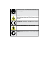
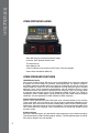

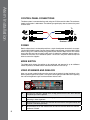
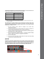
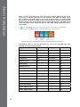
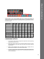
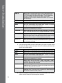
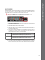
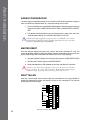
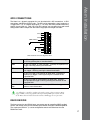
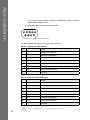
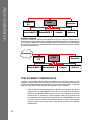
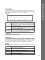
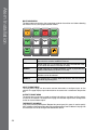


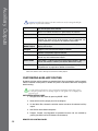
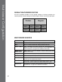
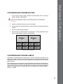
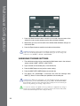


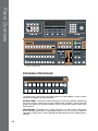
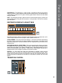
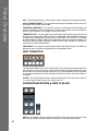
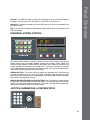

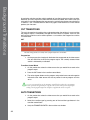
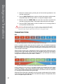
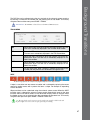
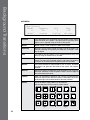

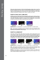
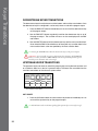
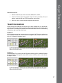
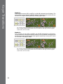

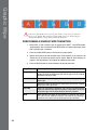


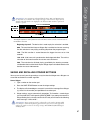
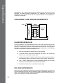
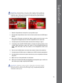

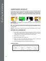
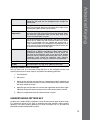
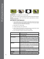
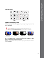
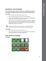
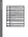
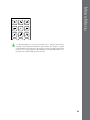


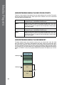
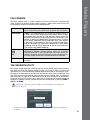
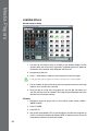
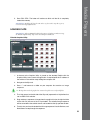
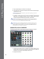

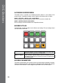
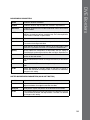
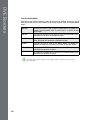
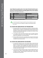


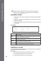

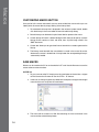
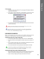
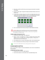
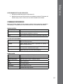

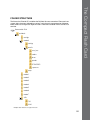

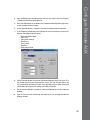
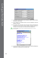
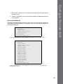
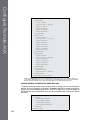
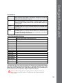
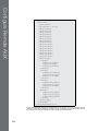
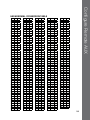

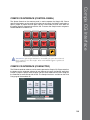

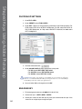
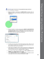


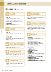
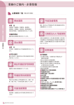


![VTW Software Operation manual[PDF:17.4MB] - FOR](http://vs1.manualzilla.com/store/data/005725901_1-df2c6d7f9199f46fcf33ffa12e63545b-150x150.png)