1
User Manual
Version 7.07
© EponaTech LLC 2013
July 2013
Use of the Manual
The Metron-MD software is designed to meet international quality and performance
standards. Personnel operating the software must have a thorough understanding
of the proper operation of the software.
This guide has been prepared to aid medical and technical personnel to understand
and operate the software. Do not operate the software before reading this manual
and gaining a clear understanding of the operation of the software. If any part of
this manual is not clear, please contact EponaTech LLC or your equipment dealer’s
representative for clarification.
The information contained herein is based on the experience and knowledge relating to
the subject matter gained by EponaTech LLC prior to publication. No patent license is
granted by this information. EponaTech LLC reserves the right to change this
information without notice, and makes no warranty, express or implied, with respect to
this information. EponaTech LLC shall not be liable for any loss or damage, including
consequential or special damages, resulting from any use of this information, even if loss
or damage is caused by EponaTech LLC’s negligence or other fault.
EponaTech LLC
6720 Linne Rd
Paso Robles, CA 93446
www.Metron-Imaging.com
Metron-MD is a registered trademark of EponaTech LLC.
Metron-MD has been granted FDA K-number K103554
Metron-MD User Manual
Version 7
© EponaTech LLC, 2013
1
Table of Contents
Use of the Manual ……………………………………………………………..... 1
Table of Contents
………………………………………………………..……... 2
Software License Agreement ………………………………................................... 3
Conventions Used in this Manual ………………………………........................... 5
Metron PC Minimum Requirements ………………………………...................... 6
Metron PC Suggested Configuration ………………………………...…………... 7
Quick-Start Guide ………………………………...……………………………….. 8
Starting Metron ………………………………....................................................... 10
The Log-In Screen ……………………………....................................................... 11
The Database Browser ………………………………........................................... 12
Multi-Image Operations ………………………………......................................... 15
Adding Images into your Metron Database ………………………………...,,,,,,, 16
Importing Images from Files ………………………………................................. 17
Single Image Tools ………………………………...……………………………… 19
Image Calibration ………………………………................................................... 21
Free Mark-Up ………………………………...………………………………....... 26
Guided Mark-Up ………………………………..................................................... 27
Report Creation ………………………………...................................................... 37
Burn CD or DVD ……………………………….................................................... 34
Export and Import of Metron Databases ……………………………….............
35
Sending Images out of Metron ………………………………............................... 37
Lossy Compression ………………………………................................................. 38
Appendix A: DICOM Support in Metron ………………………………............ 39
Appendix B: Setting up Automatic Image Rotations …………………………..
63
Appendix C: Image Stitching in Metron-MD ……………………………….....
65
Appendix D: Guided Mark-Up in Metron-MD ………………………………... 71
Metron-MD User Manual
Version 7
© EponaTech LLC, 2013
2
Software License Agreement
END-USER LICENSE AGREEMENT FOR THIS SOFTWARE
Important - read carefully:
This End-User License Agreement ("EULA") is a legal agreement between you
(either an individual or a single entity) and the author of this Software for the
software product identified above, which includes computer software and may
include associated media, printed materials, and "online" or electronic
documentation ("SOFTWARE PRODUCT"). By installing, copying, or otherwise
using the SOFTWARE PRODUCT, you agree to be bound by the terms of this
EULA. If you do not agree to the terms of this EULA, do not install or use the
SOFTWARE PRODUCT; you may, however, request a full refund.
SOFTWARE PRODUCT LICENSE.
The SOFTWARE PRODUCT is protected by copyright laws and international copyright
treaties, as well as other intellectual property laws and treaties. The SOFTWARE
PRODUCT is licensed, not sold.
GRANT OF LICENSE.
This EULA grants you the following rights: Installation and Use. You can install and use
as many copies of the software product as you have paid license fees for.
NO WARRANTIES.
The Author of this Software expressly disclaims any warranty for the SOFTWARE
PRODUCT. The SOFTWARE PRODUCT and any related documentation is provided "as
is" without warranty of any kind, either express or implied, including, without limitation,
the implied warranties or merchantability, fitness for a particular purpose, or noninfringement. The entire risk arising out of use or performance of the SOFTWARE
PRODUCT remains with you.
NO LIABILITY FOR DAMAGES.
In no event shall the author of this Software be liable for any damages whatsoever
(including, without limitation, damages for loss of business profits, business interruption,
loss of business information, or any other pecuniary loss) arising out of the use of or
inability to use this product, even if the Author of this Software has been advised of the
possibility of such damages. Because some states/jurisdictions do not allow the exclusion
or limitation of liability for consequential or incidental damages, the above limitation
may not apply to you.
DATA PRIVACY
Author of the SOFTWARE PRODUCT, has the rights to use the data content and images
to enhance the comparative database used with the SOFTWARE PRODUCT. This data
will be used in an aggregate form and will not be distinguishable per individual patient.
Metron-MD User Manual
Version 7
© EponaTech LLC, 2013
3
Conventions Used in this Manual
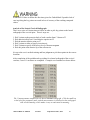
WARNING: warning points out procedures that you must follow precisely to avoid
damage to the system in the form of loss of data, or corruption of files in the software.
NOTE: Notes provide additional information, such as expanded explanations, hints, or
reminders.
IMPORTANT: Important highlights critical policy information that affects how you use
this manual and this product.
Metron-MD User Manual
Version 7
© EponaTech LLC, 2013
4
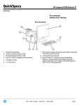
Metron Desktop PC or Laptop System Requirements – Minimum
Below are the minimum requirements for the Metron software to operate but may not
display images at the speed and image quality you might need.
Operating System
Windows XP Pro 32-bit, Windows 7 or Windows 8.
Make sure the acquisition device supports the specific operating system; some of the
older devices. Older X-Ray devices are like printers – many older printers will not work
on new computers with Windows 7 or Windows 8.
Graphics System and Monitor | Desktop PC
Widescreen 20+” monitor with a minimum resolution of 1600 x 1200 or greater / 60 Hz,
image contrast ratio – 800:1 (the higher the better), and response time of 8 ms or better plus
an independent graphics card with 512MB is strongly recommended for best image
presentation quality.
Graphics System and Monitor | Laptop
Laptop should have a 17 inch screen for best display of X-Rays. Display resolution of
1600x900 or greater with High Definition Anti-Glare display strongly recommended.
RAM
Computers running Windows XP Pro will perform best with at least 2GB of RAM.
Computers running Windows 7 or newer operating system will perform best with at least
4GB of RAM.
Disk Space
To install Metron and have needed space for the images, the desktop PC or laptop must
have at least 200GB of available disk space. Consider 350GB-1TB disk. Also consider
the new Solid State Drive (SSD) for laptops used in mobile laboratory application. They
are more tolerant of rough use.
Processor Speed
Metron will typically perform better on newer/faster desktop PC or laptop. To maximize
the speed/efficiency of the Metron program, and your overall image processing/viewing
experience, use the fastest desktop PC or laptop possible.
Internet Connection
High speed Internet connection availability is required for any desktop PC or laptop that
will be running Metron. The internet connection is critical for training & support. New
software releases are also provided automatically via internet. Also, with Metron, you can
send diagnostic images electronically to a remote radiologist; this is not possible without
an Internet connection.
Metron-MD User Manual
Version 7
© EponaTech LLC, 2013
5
WARNING: Failure to ensure that the host computer satisfies the above-stated
minimum requirements may cause Metron to be unacceptably slow or cause user interface
elements to be off-screen and un-viewable, or other problems with operation.
Metron-MD User Manual
Version 7
© EponaTech LLC, 2013
6
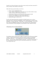
Quick Start Guide
Thank you for your purchase of Metron Software. This guide will walk you through the
simple process of installing Metron Software.
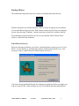
1. Load the CD (if applicable)
Load the CD into the CD Drive of your computer. The CD should auto-start and present
you with an informative installation screen. If it does not start automatically, navigate to
the CD using Explorer or My Computer and double click on “Metron.exe.”
2. Run a Downloaded Installer (if applicable)
If you do not have a CD, but have downloaded a Metron installer file, simply doubleclick this file to launch the installer. If you were given two installer files (one for ‘code’
and one for ‘data’, run both of them before attempting to enter Metron).
For a new install of Metron on a computer that it has never been installed on, you are
required to run the provided ‘Data Installer’. If it is an ‘upgrade’ install for a previously
installed copy of Metron, there is no need to run the ‘Data Installer’.
WARNING: Failure to run the provided ‘Data Installer’ during a first-time install of
Metron will result in an incomplete installation of the software. If you are not sure if the
‘Data Installer’ was previously run, always run it again (it does no harm to run it
additional times).
3. Starting the Software
After the software has installed, you will find new icons on your desktop. There are
shortcuts to the Metron manuals and the shortcut to start the Metron software:
Double-click the Metron software icon and Metron will start in trial mode.
Metron-MD User Manual
Version 7
© EponaTech LLC, 2013
7
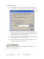
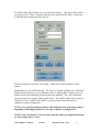
4. Unlocking the Software
4.1)
Start up Metron. In the “top-bar” (the menus across the very top of the
screen) click on the “Register” option, and then choose the “Pre-Paid” choice.
4.2)
Contact your software dealer or EponaTech LLC to obtain the Unlock Code.
They will need the “Registration Number” shown on the panel, along with
information on who the end-user of Metron will be.
4.3)
Once you get the Unlock Code, enter it in the space provided near the bottom
of the above panel, then click on the “OK” button.
4.4)
Use the “Check Status” choice under the “Register” pull-down to check if
your software is now enabled. You’re done.
WARNING: Failure to unlock the Metron software will leave your system in “Trial
Mode” which is not fully functional.
Metron-MD User Manual
Version 7
© EponaTech LLC, 2013
8
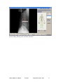
Starting Metron
The installation program has placed an icon on your desktop that looks like this:
Double clicking the icon will start Metron. If the icon does not appear on your desktop,
you can start Metron by going to the “Start” button (extreme lower left on your computer
screen), then choosing “Programs”, and then choosing “EponaTech” and then “Metron”.
The installation program also places an icon on your desktop called “Metron Guide”
which is a shortcut to this document.
When Metron Starts Up
When you first start up Metron, you will see a panel informing you that you are in “Trial
Mode”. In Trial Mode you will find many features of Metron are blocked to you. But,
you may be able to explore Metron a little bit and get a feel for it.
If you have already purchased Metron, the company you purchased it from can supply you
with an “Unlock Code” which will take you out of Trial Mode and fully enable Metron.
Metron-MD User Manual
Version 7
© EponaTech LLC, 2013
9
The Log-In Screen
Once unlocked and enabled, Metron-MD always starts by displaying the Log-In screen.
Users may log-in at three different levels: Operator, Physician, or Administrator. There is
only one administrator account. Logging in as Administrator gives you the ability to set
up other user accounts and passwords. The Administrator can also restrict privileges for
certain operations within Metron. For example, an Operator may be able to delete an
image, but may be restricted from performing a permanent delete from the Trashcan.
In a new installation of Metron-MD, it is recommended that the first time the Log-In
screen pops up, the administrator should log-in and assign their password, and set up
accounts for other users.
Note that when an Operator logs in, it is implied that he is working under the supervision
of the Physician that is displayed on the log-in screen.
The currently logged-in user of Metron is displayed in the upper blue-bar around that
main Metron window.
An image acquired by Metron-controlled hardware will be tagged with the logged-in user
at the time of acquisition. This information can later be seen by right-clicking on a
thumbnail and clicking the “Info” button.
Metron-MD User Manual
Version 7
© EponaTech LLC, 2013
10
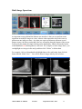
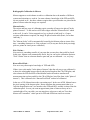
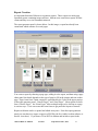
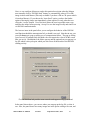
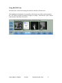
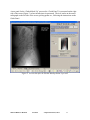
The Study List Screen
Metron always starts in the Study List screen. This is where you can browse and find all
images, video clips, and reports in your Metron database. The study list screen always
shows thumbnails (small images) for all the items in the selected study.
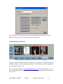
The Study List Screen
The Study List screen is like the “home page” of Metron. You always start here, and you
often come back to it. The database consists mostly of images, but can also contain video
clips, and reports. Additionally, there is something called a form, which is an image, but
it is created from several individual images arranged in a certain pattern.
Left to right: An Image, a Report, a Video Clip, and a Form.
Metron-MD User Manual
Version 7
© EponaTech LLC, 2013
11
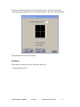
You may right click on an image thumbnail to see some information about it (for
example, its dimension sin pixels).
Right-click on an image thumbnail
The “Info” button will show you further information, including a history of where and
when this image was DICOM-sent out of Metron.
Information including the DICOM-Send History for any image.
Metron-MD User Manual
Version 7
© EponaTech LLC, 2013
12
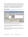
To the side of the list of studies is a set of items shown below. The top section is where
you may specify a “Filter” so that the study list only contains studies from a certain year,
or only the ones created in the last week, etc.
The next section lets you create a new study – either for an existing animal or a new
animal.
Finally there are a set of DICOM tools: The “Receive” button will blink red if a DICOM
image has been sent to your copy of Metron (unless a “Routing Rule” has been set up in
which case the received images go directly into your database). The “Q/R” button lets
you query and retrieve images from a remote PACs. The “MWL” button lets you query a
remote PACs for a worklist, and “MPPS” is used to tell that PACs that you have
completed a request imaging task.
NOTE: Your study list panel may appear with a different icon as that shown above,
depending which imaging hardware your copy of Metron is configured for.
NOTE: Under “Preferences” you can choose whether names are displayed in format
of “Last-comma-First” or not.
Metron-MD User Manual
Version 7
© EponaTech LLC, 2013
13
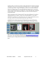
Multi-Image Operations
An important concept behind the Metron user interface is that you can perform some
operations on multiple images at a time, whereas other operations only make sense to
perform on one image at a time. Any time you want to perform an action on several
images at once, the place you do that is the row of buttons along the bottom of the screen.
You specify the images by single-clicking on the thumbnails, which will turn the border
of the thumbnail red, showing that it is selected. For example, as in the image above, you
can highlight two images in the study, and then click “Delete” to delete them.
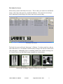
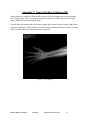
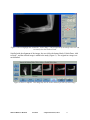
For example, click on 6 thumbnails to highlight them with a red border; then click the
button labeled “Multi View”. You will see those 6 images side by side as below:
Metron-MD User Manual
Version 7
© EponaTech LLC, 2013
14
In multi-view, below each image, you are able to zoom, and you can choose to turn off or
on any “mark up” that is drawn over the image.
Other multi-image operations that you can do are:
Delete a group of highlighted images
Export a group of images (that is, write them out to your disk in whatever image
format you choose (JPEG, Bitmap, DICOM, etc)
Print a group of images (you can choose how many per page to print)
Stitch 2 or more images into a single image (Appendix C)
Send images by DICOM (see later section in this manual)
Burn some images to a DVD or CD
Just above the buttons that perform operations on multiple images at once are three
buttons that can be used to help you highlight, or select, which images you want to do the
operation to. You can “Select All”, “Select None”, or “Select Next Region”. The “Select
Next” button will highlight all images from a certain anatomical zone, and subsequent
clicks to this button will step through the various anatomical zones found in the study.
Adding Images into your Metron Database
If your Metron software came as part of a DR or CR system, there will be an icon labeled
“Acquire” as shown above which you will click in order to acquire new radiographs.
The button “Add Form…” lets you add a Form to your study, and the button “Add
Report…” lets you create a report and add it to your study. The button “Import Image” is
the way to import any image file on your PC into Metron, and also any *.avi video file
can be imported this way.
Metron-MD User Manual
Version 7
© EponaTech LLC, 2013
15
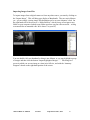
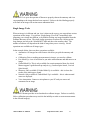
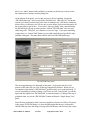
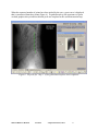
Importing Images from Files
To import images from a digital camera or from any other source, you start by clicking on
the “Import Image”. This will bring up a display of thumbnails. They are not in Metron
yet – you are simply viewing image files that happen to be on your computer’s disk. On
the right hand side of the screen is a “folder Browser” which you use to navigate to any
folder on your computer (indeed to any folder anywhere on your office network – as long
as remote disks are mounted with “drive letters” on your PC)
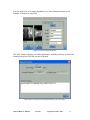
You can double-click one thumbnail to bring it into Metron, or you may highlight a group
of images and then click the button “Import highlighted Images…”. This brings to a
screen in which you see one image at a time in its full size, and with the “Anatomy
Diagram” shown on the right hand portion of the screen:
Metron-MD User Manual
Version 7
© EponaTech LLC, 2013
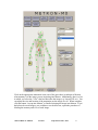
16
Click on the appropriate anatomical zone (one of the green dots) to indicate to Metron
what anatomy is in the image you are importing into Metron. Additionally, there is a list
in which you select the “View” that best describes the image (e.g. Lateral, DP, etc). You
can adjust the size and location of the annotation on the image as well. When complete,
click the button “Accept into Metron” to finalize bringing the image into Metron. If you
had selected several images, you would now see the next one; repeat the procedure of
labeling the anatomy and view of each image.
Metron-MD User Manual
Version 7
© EponaTech LLC, 2013
17
WARNING: It is up to the operator of Metron to properly choose the anatomy and view
corresponding to the image that has been acquired. Failure to do this labeling properly
will result in an image with an inaccurate annotation label.
Single Image Tools
When an image is in Metron and you view it alone on the screen, you can perform various
operations on the image. You get into “Single Image View/Edit” immediately after
importing a new image into Metron, or by double-clicking any image thumbnail from the
Database Browser screen. The single image operations are entered by clicking on the
large buttons just below the “Metron-MD” label and above the anatomy chart. The
number of buttons will depend on the kind of image that you are viewing. Not all
operations are available on all image types.
In the example below, there are these operations available:
Annotation: All images have this feature which lets you pick the anatomy and
view
Calibration: Prior to making measurements in images, you need to calibrate
Free Mark-Up: A set of tools that let you make measurements and add notes to an
image
Guided Mark-Up: This is only available for certain anatomical shots for which
Metron support a guided mark-up analysis (e.g. Lumbar Spine lateral, Cervical
Spine lateral).
Measures: Only available if Guided Mark-Up is available – this is where the
results of the mark-up are found
Normals: Only available if Guided Mark-Up is available – this is where normal
zones are displayed.
Voice Annotation: Connect a microphone to your PC and you can record
comments for an image
WARNING: Metron provides several methods to calibrate images. Failure to carefully
follow calibration procedures may result in the inability to make accurate measurements
in the affected image(s).
Metron-MD User Manual
Version 7
© EponaTech LLC, 2013
18
In the single image view/edit screen, a row of buttons across the bottom of the screen
provide image filtering tools and other functions.
Metron-MD User Manual
Version 7
© EponaTech LLC, 2013
19
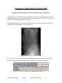
Image Calibration
Due to the nature of the geometry of radiographic imaging, all radiographs have inherent
magnification in them. For example, if one puts a ruler on a radiographic film, the
measurements one would get are not true size of the radiographed objects, but rather they
would measure larger than actual size.
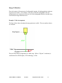
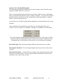
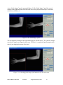
Example: Table Arrangement
The figure below shows the physical setup (patient on a table). The two numbers shown
are constant.
The two fixed offsets of importance in a table setup. Where “CR plate” is indicated, it
could instead be a DR flat plate, CCD technology, or film.
Metron-MD User Manual
Version 7
© EponaTech LLC, 2013
20
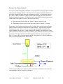
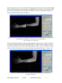
Concept: The “Plane of Interest”
To be precise with radiographic calibration, it is not possible to simply program constant
offsets into the imaging software. This is because it is subject-dependent and view or
procedure dependent exactly where the calibration is needed. An important concept is
the “plane of interest” which is a plane, parallel to the imaging plate, but offset some
distance towards the generator. Calibration can be used so that accurate measurements
can be made in this plane of interest. But, this requires that
A) The practitioner decide where the “plane of interest” should be, and
B) The imaging software must be told where this “plane of interest” is located.
For example, for a human lying on their side on a table, the best general choice for the
plane of interest would be at about half the body thickness – approximately the plane
containing the spine. However, if you were shooting radiographs intended for presurgical planning for the knee, or some other specific anatomy, the ideal choice for the
plane of interest is the plane most nearly containing those anatomical features you intend
to measure. The figure below shows the best general plane for a person lying on the
table. Of course, this is just an example, and the same applies for a subject standing in
front of a wall-mounted detector, and so forth.
The best general choice is to locate the “plane of interest” at a distance above the table
corresponding to half of the subject’s thickness.
Metron-MD User Manual
Version 7
© EponaTech LLC, 2013
21
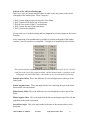
FFD, OFD, and Magnification Factor
In the Metron software we use the terms Film Focal Distance (FFD) and Object Film
Distance (OFD) to describe the physical set up and location of the plane of interest. The
FFD is the distance from the source of X-rays to the imaging plate, and OFD is the
distance from the plane of interest to the imaging plate.
Given these values, the magnification factor evident in the radiograph is:
For example, for a subject that is 6” thick (so “HB” in figure 2 is 3”) we have the values:
FFD = 37.5”
OFD = 5.0”
Which gives a magnification factor of 1.154. This means everything in the image is
11.54% bigger than true size. For all the films you shot on this system, if you were to
measure with a ruler on the film, a 10” distance along the spine would measure 11.54”
with your ruler.
Pragmatism and General Use
A great majority of radiographs of interest are not used for measurements in any way, so
none of these issues of calibration matter at all.
However, in some procedures measurements are important. It is also our belief that the
small amount of extra effort that must be expended to ensure calibrated images should be
expended for all images as a matter of standard practice. Clinics spend a great deal of
money for diagnostic imaging, and they should be able to have the benefit of accurate
measurements in the images obtained.
The current state of the art is that very few practitioners think about calibration, and
support for it in the major CR and DR systems on the market is generally lacking. The
solution adopted by some vendors is simply to add a line to the radiograph’s annotation
that states “Scale is approximate”.
Metron-MD User Manual
Version 7
© EponaTech LLC, 2013
22
Radiographic Calibration in Metron
Metron supports several schemes to achieve calibration due to the number of different
systems and situations we work in. In some schemes, knowledge of the FFD and OFD
are not required at all – but these schemes require that a special marker was placed in the
plane of interest when the image was acquired.
Metron-Scaler…
The easiest and best ways of calibrating require a marker of known size placed "in the
plane of interest". To this end we sell a little widget called the "Metron-Scaler" which
works well. It can be Velcro-strapped to a leg, or placed at 'mid body' or, if superaccurate calibration not required, can simply be placed on the table (hence, lower than
'mid body' ).
The "Metron-Scaler" will be automatically located by the Metron software (most of the
time - something obstructs it or if the exposure is off, it may not find it, then you simply
pick two points on it and you are calibrated.)
Pick 2 Points…
Next easiest is something metallic of your own that you may have that could be placed.
In this case, Metron won't automatically find it, but you can use the calibration option to
"Pick 2 Points” that are a known distance apart and you are calibrated -- so, very easy.
Known Pixel-Pitch…
Now on to ways that require knowledge of FFD and OFD:
If there is no scale marker "in the plane of interest" then the only way to get calibrated is
to know the relationship between pixels and physical length on the CR or DR plate, and
also to know the FFD and OFD so that Metron can do the math to transform all
measurement into a plane parallel to the CR or DR plate, but offset from it (the "plane of
interest"). This is known as the “Known Pixel Pitch” method of calibration.
In the case of CR, Metron knows the scan setting used. In the case of DR, Metron knows
the pixel spacing of the detector plate. But to transform the measurements (that is, to
"take the magnification out") we must have the FFD and OFD, and this is entered into the
calibration panel. In case you want an approximate plane of interest always to be a
certain height off or your table, you can enter these values once, and you’ll see that
Metron will “remember” values put in for FFD and OFD from session to session.
Metron-MD User Manual
Version 7
© EponaTech LLC, 2013
23
WARNING: Metron provides several methods to calibrate images. Failure to carefully
follow calibration procedures may result in the inability to make accurate measurements
in the affected image(s).
Metron-MD User Manual
Version 7
© EponaTech LLC, 2013
24
Free Mark-Up
The Free Mark-Up panel provides a number of different measuring and annotation
options.
NOTE: If you elected not to calibrate the current image, then many of the
measurement tools shown above will be absent from this panel.
Metron-MD User Manual
Version 7
© EponaTech LLC, 2013
25
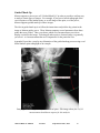
Guided Mark-Up
Metron supports a process we call “Guided Mark-Up” in order to provide a uniform way
to analyze certain types of images. For example, if you have a lateral radiograph of the
cervical spine or of the lumbar spine, or an AP image of the spine, or of the pelvis,
Metron supports guided mark-up of these images.
The idea in guided mark-up is to follow the instructions and pick the key points in the
image as Metron guides you to. Then, Metron computes several parameters from these
points that were picked. Then, you choose which set of measurements you wish to
display overlaid on the image. Selecting all makes quite a cluttered image, so generally
you select 1 to 4 measurements that are of importance for the particular case.
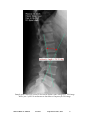
Appendix D provides a step-by-step illustration of the guided markup process using a real
lateral lumbar spine radiograph as an example.
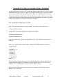
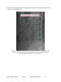
Sample guided mark-up results for the cervical spine. This image shows just 1 of 10
measurements that Metron reports for this analysis.
Metron-MD User Manual
Version 7
© EponaTech LLC, 2013
26
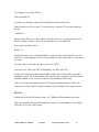
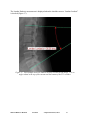
Sample guided mark-up results for the lateral lumbar spine radiograph. This image
shows just 1 of the 10 measurements that Metron computes for this image.
Metron-MD User Manual
Version 7
© EponaTech LLC, 2013
27
WARNING: Failure to follow the directions given for Guided Mark-Up and/or lack of
care in picking the key points can result in loss of accuracy of the resulting computed
values.
Analysis of the Lateral Cervical Radiograph
There are a series of 6 instructions to follow in order to pick key points on the lateral
radiograph of the cervical spine. These 6 steps are:
1. Pick 2 points on the posterior body of each vertebra from C1 down to T1
2. Pick anterior inferior on C4 and anterior superior on C5
3. Pick the anterior inferior point on C7
4. Pick 2 points on Atlas to specify its main axis
5. Pick 2 points to specify skull base at level of foramen magnum
6. Pick one point at the anterior lip of the sella turcica
It is up to the user’s medical training and best judgment to pick these points in the correct
locations.
After completion of the guided mark-up picking for a lateral radiograph of the cervical
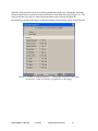
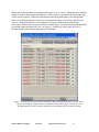
vertebra, a set of 11 measures are computed. A sample set of numbers are shown below.
.
The 11 measurements computed for the lateral cervical radiograph. Click the small box
to the left of the parameter name, and the measurement is visualized on the radiograph
with overlaid markup, which makes it easy to understand its meaning.
Metron-MD User Manual
Version 7
© EponaTech LLC, 2013
28
Note that for proper interpretation of these measures, the patient must be positioned
appropriately. Here are some brief notes and comments on each of the measures:
Atlas Angle: The angle that the major axis of C1 (from this aspect) makes with the
horizontal.
Atlas/Axis Angle: The perpendicular to the posterior side of the C2 body is constructed,
and the angle between this constructed line and the major axis of C1.
Atlas/Skull Angle: The angle between a line at the base of the skull (at the level of the
foramen magnum) and the major axis of C1.
Occiput Angle: The angle between a line at the base of the skull (at the level of the
foramen magnum) and the horizontal.
Jackson’s Angle: The angle between two constructed lines: one at the posterior of the
body of C2, and the other at the posterior of the body of C7.
Cervical Lordosis: The angle between two constructed lines: one along the major axis
of C1, and the other along the inferior side of the body of C7.
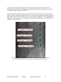
George’s Deviation: George’s line is the curve created by connection points chosen on
the posterior sides of all vertebral bodies. According to some literature, in the ideal case
these points lie on a circular arc. Metron’s “George’s Deviation” parameter is a sum of
all the offsets from this perfect circular arc. A perfect value would be zero ( 0.0 )
meaning that all points lie on a perfect circular arc. The higher the value of this
parameter, the more deviation there is from a circular arc. In blue, the “ideal arc” is
shown.
C1-T1 Offset: Construct a line from the inferior posterior corner of the T1 body
vertically in the image, and then measure horizontal displacement of the superior
posterior corner of the C1 body. Some literature suggests this value be “small”.
C2-C7 Offset: Construct a line from the inferior posterior corner of the C7 body
vertically in the image, and then measure horizontal displacement of the superior
posterior corner of the C2 body. Some literature suggests this value be “small”.
Gravity Line Offset: Some literature suggests that a point at the anterior lip of the sella
turcica serves as a good reference of the center of mass of the head, and further that a line
dropped vertically from that point should pass “near” the disc space between C4 and C5.
This parameter gives this measure.
Actual Arc: Some literature suggests that the arc fitting thru the vertebrae should be a 42degree section of a circle. This parameter shows the actual value of the best-fit arc.
Metron-MD User Manual
Version 7
© EponaTech LLC, 2013
29
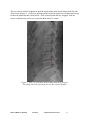
Analysis of the Lateral Lumbar Radiograph
There are a series of 5 instructions to follow in order to pick key points on the lateral
radiograph of the lumbar spine. These 5 steps are:
1. Pick 2 points on the posterior body of each vertebra from L5 up to T12
2. Pick 2 superior points on S1
3. Pick anterior inferior point on L5
4. Pick 2 points on the anterior body of L3
5. Pick 2 points on the anterior body of T12
It is up to the user’s medical training and best judgment to pick these points in the correct
locations.
After completion of the guided mark-up picking for a lateral radiograph of the lumbar
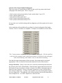
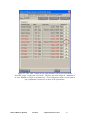
vertebra, a set of 11 measures are computed. A sample set of numbers are shown below.
The 11 measurements computed for the lateral lumbar radiograph. Click the small box
to the left of the parameter name, and the measurement is visualized on the radiograph
with overlaid markup, which makes it easy to understand its meaning.
Note that for proper interpretation of these measures, the patient must be positioned
appropriately. Here are some brief notes and comments on each of the measures:
George’s Deviation: George’s line is the curve created by connection points chosen on
the posterior sides of all vertebral bodies. Some literature suggests that in the ideal case
these points lie on a smooth curve which is a section of an ellipse with certain major-tominor axis ratio. Metron’s “George’s Deviation” parameter is a sum of all the offsets
from a best-fit elliptical arc. A perfect value would be zero (0.0) meaning that all points
lie on an elliptical arc. The higher the value of this parameter, the more deviation there is
from an elliptical arc. An “ideal” elliptical arc is drawn in blue.
Metron-MD User Manual
Version 7
© EponaTech LLC, 2013
30
Jackson’s Angle: The angle between two constructed lines: one at the posterior of the
body of L1, and the other at the posterior of the body of L5.
Ulman’s Measure: A perpendicular to the sacral base line is created at the sacral
promontory. L5 should be at or behind this line. Ulman’s measure quantifies how far
anterior to this line L5 lies in terms of a percentage of the vertebral body’s size.
Gravity Offset: A vertical line is constructed from the centroid of the L3 body. Some
literature suggests that this line should pass “near” the sacral promontory. The ‘Gravity
Offset’ parameter measures this distance.
L5-T12 Offset: Construct a line from the inferior posterior corner of the L5 body
vertically in the image, and then measure horizontal displacement of the inferior posterior
corner of the T12 body. Some literature suggests this value be “small”.
Lumbar Lordosis: The angle between two constructed lines: one along the inferior side
of the T12 body, and the other along the sacral base line.
L1-2 Angle: The angular change in going from the L1 body to the L2 body - measured by
comparing lines constructed along the posterior side of each vertebral body. Some
literature suggests the ideal value is 2.5 degrees.
L2-3 Angle: The angular change in going from the L2 body to the L3 body - measured by
comparing lines constructed along the posterior side of each vertebral body. Some
literature suggests the ideal value is 6.3 degrees.
L3-4 Angle: The angular change in going from the L3 body to the L4 body – measured by
comparing lines constructed along the posterior side of each vertebral body. Some
literature suggests the ideal value is 9.7 degrees.
L4-5 Angle: The angular change in going from the L4 body to the L5 body – measured by
comparing lines constructed along the posterior side of each vertebral body. Some
literature suggests the ideal value is 15.9 degrees.
Actual Ellipse: This gives the minor-axis to major-axis ratio of the best-fit ellipse used in
the Georges line deviation parameter. Some literature suggests that a normal value is
0.39.
Metron-MD User Manual
Version 7
© EponaTech LLC, 2013
31
Analysis of the AP Spine Radiographs
The following guided-markup analysis can be used for images of any of the three spine
segments: Lumbar, Thoracic, or Cervical.
There is a single guided mark-up instruction to pick three points on each vertebral body.
These picks are then repeated on as many vertebrae as desired. Two points are picked on
symmetric features on each side of the vertebral body, and the third point is a centered
feature, such as the spinous process.
It is up to the user’s medical training and best judgment to pick these points in the correct
locations.
After completion of the guided mark-up picking for a AP radiograph of the spine
vertebra, a set of 3 measures are computed. A sample set of numbers are shown below.
The 3 measurements computed from the analysis of an AP view of the spine. Click the
small box to the left of the parameter name, and the measurement is visualized on the
radiograph with overlaid markup, which makes it easy to understand its meaning.
Max Cobb Angle: This is the largest angular difference between any two vertebrae.
Max Angular Deviation: This is the largest angular value (away from vertical) of any
vertebra.
Max Linear Deviation: A vertical blue line is drawn on the image starting at the center
of the lowest vertebra picked. This is the largest distance horizontally away from this
central line of the center of any vertebra.
Metron-MD User Manual
Version 7
© EponaTech LLC, 2013
32
Analysis of the AP Pelvis Radiograph
There are a series of 5 instructions to follow in order to pick key points on the lateral
radiograph of the lumbar spine. These 5 steps are:
1. Pick 2 points: highest points on each side of the illium
2. Pick 2 points to indicate the top of the sacrum
3. Pick the four corners of the L5 vertebral body
4. Pick 2 points: the tops of the femur heads
5. Pick 1 point at the symphysis
It is up to the user’s medical training and best judgment to pick these points in the correct
locations.
After completion of the guided mark-up picking for a lateral radiograph of the lumbar
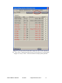
vertebra, a set of 8 measures are computed. A sample set of numbers are shown below:
The 8 measurements computed from the analysis of an AP view of the pelvis. Click the
small box to the left of the parameter name, and the measurement is visualized on the
radiograph with overlaid markup, which makes it easy to understand its meaning.
Femur Linear Offset: This is the difference in vertical height between the tops of the
femur heads.
Femur Angular Ofset: This is the angle that the line connecting the tops of the femur
heads makes with a horizontal.
Illium Linear Offset: This is the difference in vertical height between the tops of the
Ilium.
Illium Angular Ofset: This is the angle that the line connecting the tops of the left and
right Ilium makes with a horizontal.
Sacral Base Angle: This is the angle made by the base of the sacrum relative to the
horizontal.
Metron-MD User Manual
Version 7
© EponaTech LLC, 2013
33
L5 Angle: This is the angle made by the base of L5 relative to the horizontal.
Symphsis-L5 Offset: This is the horizontal offset from the center of the L5 body to the
center of the symphsis.
Pelvis Width: This is the distance between the tops of the femur heads.
WARNING: It is the responsibility of the Metron user to interpret the results of the
guided mark-up analysis. EponaTech LLC assumes no liability for the improper use of
these results. Metron software is a tool to make physical measurements from calibrated
images, it is not a diagnosis system. All diagnoses must be made by licensed
professionals.
Metron-MD User Manual
Version 7
© EponaTech LLC, 2013
34
Report Creation
An important function of Metron is to generate reports. These reports are multi-page
formatted reports containing images and text. Metron users create these reports for their
clients and they are a vital communication tool.
The report generator panel is shown below. In this image, a report has already been
constructed which consists of several pages.
You create a report by choosing a page type, adding it to the report, and then using a page
editor panel (its details depends on the type of page) to fill in the images and text on that
page. Pages come from 2 main categories, represented by the 2 tabs in the upper portion
of the repot generator panel: “Generic Pages”, and “Form Pages”. Most reports are built
from “Generic Pages”; the “Form Pages” allow multiple images to be laid out on a page
in various ways. Users can create their own forms to get particular layouts of interest.
Reports in Metron can be re-opened and edited at any time. From the report generator
panel you can choose to export a report as a PDF file (the free Adobe Acrobat software is
need to view these). If you burn a CD or DVD in Metron and include a report in the
Metron-MD User Manual
Version 7
© EponaTech LLC, 2013
35
study that goes onto the disk, it will automatically be converted to a PDF file and put on
the disc. This way, the recipient of your CD will not be able to edit the report. Likewise,
you can e-mail a report directly from your Metron database, and it will be converted to a
PDF file and attached to the e-mail. There is also a choice in the e-mail panel which will
let you send a report (as well as anything else in your Metron database) by e-mail to
another Metron user who will then be able to bring the items into their own copy of
Metron. In that case, it is not a PDF file that is sent, but a fully editable report.
Burn CD or DVD
Another important function is to burn a CD or DVD with images and other items to be
given to another person. The panel is shown below:
By default, the CD or DVD created by Metron will also contain a “mini-Metron” viewer
so that the recipient of the disk can view the images and reports easily.
To write a “partial study” onto a CD, highlight the thumbnails of the images you want to
select prior to entering the Burn CD panel. From within the panel, you can include
additional full studies on the disk.
There is an option at the top of the panel to write a disk without the min-Metron viewer,
but rather with images only. If you choose this style of disk, you can select the format of
the images: JPEG, TIFF, or DICOM.
Metron-MD User Manual
Version 7
© EponaTech LLC, 2013
36
Export and Import of Metron Databases
There are several reasons why you might want to import or export an entire Metron
database, or a portion of one. For example:
To make a back-up of your database, export a copy of it to another disk
To merge images from a portable Metron-based system that went out into the field
back into your main database at your office
To give a copy of part or all of your database to a colleague.
These things are found under the “Database” entry in the top-bar of Metron.
It is important to note that in the upper right hand corner of the Database Browser the
“current database” you are viewing is shown. This is usually “Default”. Some Metron
users will only ever have this database. In fact, unless there is a good reason to have
multiple databases, it is simplest to just have one. In the database tools, the terms
“Export” and “Import” are always meant relative to the current Metron database. That is,
you “export out of” the current database, or “import into” the current database.
You can export your database or a portion of it onto a thumb-drive, then carry it to
another computer with Metron, then import from the thumb-drive into the database of
that Metron. In the Export Database panel, there is also the ability to export the current
database to a CD or DVD. This is a way to accomplish a back-up of your database.
WARNING: It is up to the operator of Metron to perform timely back-ups of the Metron
database and any other data of importance. Metron contains no automated back-up
facility. Back-ups are the responsibility of the user or clinic staff.
Metron-MD User Manual
Version 7
© EponaTech LLC, 2013
37
A subset of the entire database can be specified by giving a range of dates of the studies.
It is often convenient to export only the studies created in, say, the prior week and merge
them into some other database.
Metron-MD User Manual
Version 7
© EponaTech LLC, 2013
38
The “Database Tools” panel gives you a way to count how many images are in your
database, and to see the total size your images occupy on disk.
Sending Images out of Metron
To send images out of Metron via the internet, click “Send Images”
In order to send by DICOM, first go to “Preferences”, then choose “DICOM Preferences”
and then configure a server to which you will send. You will have to ask the recipient for
the coordinates of their server.
You may also post images to www.MetronWebViewer.com for your colleagues to view
there. All images posted to our server are encrypted and userid and password protected at
the web-site.
Metron-MD User Manual
Version 7
© EponaTech LLC, 2013
39
Lossy Compression and Compression Ratios
By default, Metron-MD does not apply image compression. So, the general user will not
create nor view images which have been compressed in any way.
However, Metron-MD does provide some image compression tools which an end-user
may choose to apply.
There are 2 places in Metron-MD where image compression might be applied, these are:
1) When sending images via DICOM send
2) When saving an image to a file, when JPEG is selected.
Here is compression-ratio information for both of these situations:
1) DICOM send
By default when a DICOM server is specified in Metron, the transfer syntax is set to code
2, which stands for 'Implicit Little Endian', and the image is sent in full-fidelity with no
compression applied. If the user so chooses, he may select a different setting for transfer
syntax. If any method is chosen which applies compression, the user is able to specify the
desired compression ratio by giving a number between 2 and 255, where 2 specifies the
least compression, and 255 specifies the most compression. In such cases the
compression ratio in effect is approximately the value specified divided by 5. That is, a
value of 100 would specify a 20-to-1 compression ratio. Such a formula is approximate,
as it depends on the particular image content (images with little detail can be highly
compressed, whereas image with lots of detail do not compress by as high a ratio).
2) When saving an image as a JPEG
These images are saved as JPEG images with a fixed quality metric of 95%, which
corresponds to a compression ratio of approximately 8-to-1. This is not user-adjustable.
Metron-MD User Manual
Version 7
© EponaTech LLC, 2013
40
Appendix A: DICOM Support in Metron
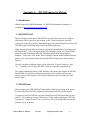
1. Introduction
Metron supports the DICOM standard. A "DICOM Conformance Statement" is
available at http://www.metron-imaging.com.
2. DICOM File I/O
Metron can import and export a DICOM files in exactly the same way as it imports
and exports files of types like jpeg, bitmap, or tiff. When you browse your disk
looking for images from Metron, thumbnails appear for each folder that you select, and
DICOM images will be displayed just like the other image types.
When importing image files into Metron, look for the button labeled "Auto-Import all
DICOM Images" -- this will import all the DICOM images found in a selected folder,
and will use the information in the DICOM tags to place them into the Metron
database. At any time, click on the "Receive Images" button (in the Database Browser
panel) to see a log showing where all imported DICOM images have been stored in
Metron.
Likewise, anyplace in Metron where you are allowed to “Export” images or “Save
As…” an image, you will find “DICOM” on the list of possible output formats.
The simple reading and writing of DICOM files is the most basic support for DICOM.
But DICOM also specifies a communication protocol for sending and receiving
images across a local network or the internet, and these topics are addressed in the
next sections.
3. DICOM Send
Metron supports the “DICOM Send” functionality, allowing any image in Metron to
be sent to any other DICOM-compliant product located anywhere on the internet.
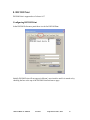
To prepare to send via DICOM, you must first define a DICOM system that you will
send to. This is done by going to "Preferences" in the top-bar, then choose "DICOM
Preferences". On the "Servers" tab, you will see a list of all the DICOM systems that
you have set up in Metron.
Metron-MD User Manual
Version 7
© EponaTech LLC, 2013
41
This panel lists all the servers you have configured Metron for. Additionally, you can
indicate your favorite server to Query and Retrieve from, and your favorite server to
fetch Worklists from.
A new DICOM system can be added to the list by clicking the “New…” button just to
the right of the list, and a server can be removed by highlighting one and then clicking
the “Del…” button. The settings for each server can be reviewed and possibly edited
by highlighting one and clicking the “Edit…” button. Doing this brings up the
DICOM Peer panel shown below.
WARNING: Failure to properly configure the Peer address, Peer Port, and Peer AE
Title will result in Metron's inability to send DICOM images to that server. Always
click the "Test this Connection" button to ensure that these values have been properly
specified.
Metron-MD User Manual
Version 7
© EponaTech LLC, 2013
42
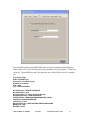
Use this panel to define a new DICOM system,
or edit one that you previously set up.
The Peer Address, Peer Port, and Peer AE values must be given to you by whoever
you wish to send a DICOM image to. These three values specify a particular DICOM
enabled product somewhere on your local network or out on the internet somewhere in
the world. The “Nickname” is chosen by you as a handy way to remember what each
of these DICOMs servers is. Once you have filled in the top portion of the panel, you
can click the “Test This Connection” button to quickly check if the DICOM server can
be found.
The next items are for specifying “Transfer Syntax” and “Compression”. If you are
unsure of these settings, you can set both values to “2” in order to send full-sized
uncompressed images which will be of the highest quality (but perhaps large and slow
to send). Click on the button labeled “?” to see other possible settings. You probably
should discuss this with the person in charge of the DICOM system you are sending to,
Metron-MD User Manual
Version 7
© EponaTech LLC, 2013
43
as they may have a preference, or it may be the case that their DICOM system cannot
accept all possible transfer syntaxes. Again, choosing “2” and “2” is a safe choice, and
it is the default in Metron. Here is more information on the values that you can use
for these two settings:
Use an integer code to select the desired transfer syntax:
2 = IMPLICIT_VR_LITTLE_ENDIAN = "1.2.840.10008.1.2"
21 = EXPLICIT_VR_LITTLE_ENDIAN = "1.2.840.10008.1.2.1"
22 = EXPLICIT_VR_BIG_ENDIAN = "1.2.840.10008.1.2.2"
25 = RLE_LOSSLESS = "1.2.840.10008.1.2.5"
2199 = DEFLATED_EXPLICIT_VR_LITTLE_ENDIAN = "1.2.840.10008.1.2.1.99"
2450 = JPEG_BASELINE_1 = "1.2.840.10008.1.2.4.50"
2451 = JPEG_EXTENDED_2_4 = "1.2.840.10008.1.2.4.51"
2452 = JPEG_EXTENDED_3_5 = "1.2.840.10008.1.2.4.52"
2453 = JPEG_SPECTRAL_NONHIER_6_8 = "1.2.840.10008.1.2.4.53"
2454 = JPEG_SPECTRAL_NONHIER_7_9 = "1.2.840.10008.1.2.4.54"
2455 = JPEG_FULL_NONHIER_10_12 = "1.2.840.10008.1.2.4.55"
2456 = JPEG_FULL_NONHIER_11_13 = "1.2.840.10008.1.2.4.56"
2457 = JPEG_LOSSLESS_NONHIER_14 = "1.2.840.10008.1.2.4.57"
2458 = JPEG_LOSSLESS_NONHIER_15 = "1.2.840.10008.1.2.4.58"
2459 = JPEG_EXTENDED_HIER_16_18 = "1.2.840.10008.1.2.4.59"
2460 = JPEG_EXTENDED_HIER_17_19 = "1.2.840.10008.1.2.4.60"
2461 = JPEG_SPECTRAL_HIER_20_22 = "1.2.840.10008.1.2.4.61"
2462 = JPEG_SPECTRAL_HIER_21_23 = "1.2.840.10008.1.2.4.62"
2463 = JPEG_FULL_HIER_24_26 = "1.2.840.10008.1.2.4.63"
2464 = JPEG_FULL_HIER_25_27 = "1.2.840.10008.1.2.4.64"
2465 = JPEG_LOSSLESS_HIER_PROCESS_28 = "1.2.840.10008.1.2.4.65"
2466 = JPEG_LOSSLESS_HIER_PROCESS_29 = "1.2.840.10008.1.2.4.66"
2470 = JPEG_LOSSLESS_NONHIER_14B = "1.2.840.10008.1.2.4.70"
2490 = JPEG2000_LOSSLESS_ONLY = "1.2.840.10008.1.2.4.90"
2491 = JPEG2000 = "1.2.840.10008.1.2.4.91"
For transfer syntaxes that use compression, you may specify how much
compression to use by giving an integer on the range [2..255] where
2 specifies the least compression (highest quality) and 255 specifies
the most compression. For transfer syntaxes which don't use compression
this value is ignored.
WARNING: The default settings of 2 and 2 in the DICOM Peer panel will ensure that
no compression of the image will occur. Some other choices (e.g. 2490 for the first
setting) also employ "lossless" compression scheme with which full fidelity of the
image is maintained. Some other settings may cause "lossy" compression to be used
which may remove detail or contrast from the image, or may introduce artifacts.
Metron-MD User Manual
Version 7
© EponaTech LLC, 2013
44
Next, we can configure Metron to send to this particular recipient when the Metron
user manually clicks a “DICOM Send” button, or, automatically when a CR or DR
image is taken with Metron (This only available if you have a DR or CR system which
is based on Metron). If you choose the “Auto-Send” option, you have the further
option of having the image sent immediately when acquired, or only when the user
clicks the “Accept” button. Use of the later allows the user to possible rotate, crop,
and filter the image before pressing “Accept” to save the image locally and send it out
via DICOM communications.
The last two items in the panel allow you to configure the behavior of the DICOM
send function should the transmission fail, or should it succeed. Note that in any case
you will always get a pop-up telling you of a transmission failure. The pop up telling
you of success is optional (only downside: the click required to clear it off the screen
after you see it). In addition to the failure pop-up and the optional success pop-up is a
log file which is always kept in which you can review all the details of the DICOM
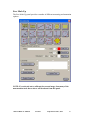
sending activity.
The DICOM Send tab provides some controls and supports a log of all sends.
In the panel shown above, you can see where you can pop up the log file, or clear it
out. Also, the panel shows how many images are in the queue waiting to be sent, and
Metron-MD User Manual
Version 7
© EponaTech LLC, 2013
45
there is an “Abort” button in the (unlikely) event that you decide you want to cancel
the transmission of images awaiting being sent.
At the bottom of the panel, you see that you have a choice regarding viewing the
“DICOM header tags” when you perform a DICOM send. Choosing “No” means the
system won’t show you these tags at the time of sending at all – this choice minimizes
mouse clicks, as otherwise you will use one or more mouse clicks to take this panel off
the screen when a send occurs. If you select “Once per Study” then a panel showing
the DICOM tags will pop up when you have clicked “DICOM Send” once for each
study being sent. This gives you a chance to review the tags – if you spot something
wrong, there is a “Cancel Send” button so you could cancel the send, got fix the tags,
and then send again. The panel shown below shows the DICOM header tags.
The DICOM Data panel.
The most important tags are displayed in this panel. An item near the lower left
portion of this panel lets you view all the tags supported by Metron. When you are
viewing these tags during a “DICOM Send” operation, they are in read-only mode. If
you see something you need to change, you’ll have to click “Cancel Send”, go edit the
tag(s) and then again click “DICOM Send” to send the image(s). Editing of the tags is
permitted when you see the “DICOM Data” button in Metron's “Single Image View”
panel.
Since Metron, particularly when is used as acquisition software of a DR or CR system,
is the source of DICOM images, we have the philosophy that the user is allowed to
edit DICOM tags since the image is being created in Metron, and obviously the creator
Metron-MD User Manual
Version 7
© EponaTech LLC, 2013
46
needs to be able to set the tags as needed. On the other hand, since Metron can import
DICOM files that may have come from other DICOM sources, it is not recommended
to edit the tags of those “foreign” DICOM files. While it is not strictly forbidden in
Metron, the editing of tags of a foreign DICOM file in Metron causes a record to be
kept in a special log file known as an Audit Trail. This would allow some responsible
person to make a review and learn that Metron was used to alter DICOM tags in a
foreign DICOM file.
Metron encapsulates all the “Metron specific” data such as calibration, free mark-up,
and guided mark-up, etc inside a “Private Tag” in the DICOM file. If you send a
DICOM file from Metron to another Metron user, the recipient will be able to receive
the image, and all of its mark-up and data into their copy of Metron.
A DICOM Send is initiated from the main Database Browser panel of Metron by
highlighting one or more thumbnail images, and clicking the "Send Images" button.
There are 3 ways to send images: DICOM, post to http://www.metronwebviewer.com,
or by e-mail. You can select your default or favorite method in the general
preferences panel, or simply choose the method each time you enter the Send Images
panel.
Metron-MD User Manual
Version 7
© EponaTech LLC, 2013
47
Mark the check box for one or more recipients and click 'Send'.
Metron-MD User Manual
Version 7
© EponaTech LLC, 2013
48
4. DICOM Receive
If DICOM images are sent to Metron, the “Receive Images” button in the Database
Browser panel will begin to blink within 7 seconds of the image(s) arriving. By
clicking on the Receive Images button you can see a transcript showing where they
will go in Metron when you click on the “Import” button there. We will also discuss
"auto-import" below - in this scheme the button does not blink and arriving images
are silently accepted into your Metron database.
To configure the system which will send DICOM images to Metron, you need to
know three things: the IP address of the PC that Metron runs on; the Port that Metron
listens on (default value is 4002); and the name, or “AE Title” of Metron (default
value is METRON_AE). With those three bits of information the system which will
send images to Metron can be configured. The Port and AE Title used by Metron can
be changed on the DICOM Receive tab if need be.
If you do not know the IP address of your computer, you can find out by going to the
site http://www.ipchicken.com which will display your IP address.
DICOM Receive tab: Configure auto-importing of native DICOMs
and/or routing rules for recognized foreign DICOMs.
Metron-MD User Manual
Version 7
© EponaTech LLC, 2013
49
Receiving "Native DICOMs" and "Recognized Foreign DICOMs"
A "Native DICOM" is one which was created on a Metron system, and therefore it has the
special 'private data tag' which holds all of the original Metron information (calibration,
markup, measurements, etc). Generally it is a good idea to choose to auto-import them
directly into the Metron database (this is the default setting). When Metron is configured
to auto-import these DICOMs, their arrival will not cause the "Receive Images" button to
blink red, rather, they will be silently and automatically inserted into the Metron database.
A record of their auto-importation is kept in the Receive Images log, so you can always
check the log and see that this has occurred.
A "Recognized Foreign DICOM" is one that did not originate from a Metron system, but
it is from a system that Metron can recognize. For example, Metron knows how to tell
that a DICOM file originated from an Eklin DR system. If Metron can recognize the
source of the DICOM file, Metron can know where to look to find the anatomical region,
and other details. Some of these details are not always in standard locations despite the
DICOM standard.
DICOM Receive tab with a Routing Rule specified.
Metron-MD User Manual
Version 7
© EponaTech LLC, 2013
50
In the panel shown above, a "routing rule" has been created called "Eklin Rule". You
click on the "New..." button to create a new routing rule, or click on "Edit..." to view or
modify an existing routing rule. The panel below shows the definition of the "Eklin
Rule":
Example of a Routing Rule.
The "Nickname" can be chosen as you wish. The important keyword "Eklin" has been
inserted in the "For DICOMs from:" field. Please ask EponaTech if Metron knows how
to recognize DICOMs from a particular system of interest, and what the corresponding
keyword is for that system.
This routing rule says that if a DICOM arrives that is recognized as being from an Eklin
system, it will be auto-imported into the current Metron database, and will be converted
to a native Metron image. Further, it will be automatically filtered with "Detail 2" from
the filter-set called "Canon".
Note: The only way that a foreign DICOM can be auto-imported into Metron's database is
by use of a routing rule. If not matching routing rule is found, they will arrive in
"pending" mode, and the Receive Images button will blink red to alert you.
Metron-MD User Manual
Version 7
© EponaTech LLC, 2013
51
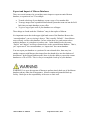
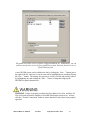
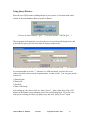
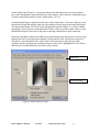
Special Requirement when Installing on Windows 7
After installing Metron on a Windows 7 computer, there are a few more steps that need
to be done to enable it for DICOM receive. These things occur automatically on
Windows XP, but for Windows 7, which has a stricter security environment, these things
must be done manually. This is a one-time operation, performed just once after installing
Metron.
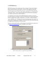
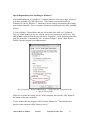
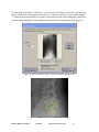
1) Look in folder C:/Epona/Diclis and you will see three files with “exe” extensions.
They are called: launch_service.exe, metron_service.exe, and remove_service.exe. For
each of these, right-click on the file, and choose “Properties”. In the properties panel that
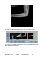
pops up, choose the “Compatibility” tab. As shown in figure 1 below, check the box
labeled “Run this program as an administrator”.
Set a program to “Run as Administrator”. Repeat this for 3 programs in the
C:/Epona/Diclis folder.
Make sure to enable this setting for all 3 of the programs, and click the “OK” button at
the bottom of the panel each time.
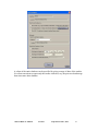
2) Now double-click the program called “Launch_Metron.exe”. This should start a
process on the computer called “Metron_Service”.
Metron-MD User Manual
Version 7
© EponaTech LLC, 2013
52
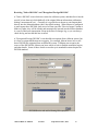
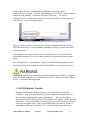
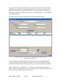
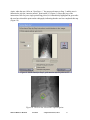
3) Now check with the Task Manager to see that there is a process called
“Metron_Service” running. To get the Task Manager, do a CTRL-ALT-Delete and then
choose the Task Manager. Choose the tab labeled “Processes”. To check if
“Metron_Service” is running, you may have to click on the choice to “show processes
from all users”. See screen capture below.
Click this button for a full listing of all running processes.
If you see “Metron-Service” is running, you are done, and Metron is ready to receive
DICOM transmissions. If it is not running, something is wrong, so please check these
instructions again.
If you shutdown the computer and re-boot, the “Metron_Service” process should be
automatically started for you, so you should not have to perform any of these actions
again.
The “Metron-Service” is the thing that “listens” for DICOM files that might be sent to
Metron, so it needs to be running in order for DICOM Receive to function in Metron.
WARNING: Failure to perform these steps when installing on a Windows 7 computer
will make Metron unable to receive DICOM files sent to it. Always verify that "Metron
Service" is running in the background.
5. DICOM Modality Worklist
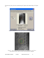
Modality Worklist allows Metron to query s remote DICOM server to fetch
“worklists”. That is, Metron can query a practice management system to ask “are
there scheduled appointments requiring radiography?”. This way, the patient
information entered in the PM system can be transferred to Metron. In the “DICOM
Preferences” Servers panel there is a setting where you indicate which server will be
used to fetch worklists from. Then, on the Database Browser panel of Metron, a
small button in the lower left labeled “W L” can be clicked to query that server.
Metron-MD User Manual
Version 7
© EponaTech LLC, 2013
53
Using the Worklist panel, the technician at Metron can see the schedule of upcoming
exams. Any given exam can be used to create a new patient in Metron - thus avoiding
re-entering of patient information in Metron.
6. DICOM Compliant CDs
DICOM compliant CDs and DVDs can be written by Metron. This function is found
in the Database Browser panel and is labeled “Burn CD/DVD”. To send a partial
study, highlight the thumbnails of the images you wish to include before going into the
Burn CD/DVD function. Adding of full studies can be done from within that panel.
These CDs contain the images in DICOM format as well as a viewer program (which
resembles Metron itself) so that the CD you create may be sent to a recipient and they
can view the images directly off the CD without the need for any particular software
on their PC.
Alternate DICOM viewers can also view the images on the CD because the CD, in
addition to the images, contains the required DICOMDIR file which some systems
require.
Metron-MD User Manual
Version 7
© EponaTech LLC, 2013
54
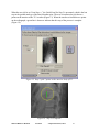
7. Query/Retrieve from a Remote Server
Introduction
Metron supports the client side ( or “SCU” ) of the DICOM Query/Retrieve capability.
By this means, Metron can pull images from a DICOM PACs system back to Metron.
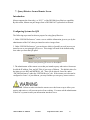
Configuring Systems for Q/R
The following steps must be taken to prepare for using Query/Retrieve:
1. Under “DICOM Preferences” create a server with the information given to you by the
administrator of the PACs that you intend to retrieve images from.
2. Under “DICOM Preferences” you can choose which (of possibly several) servers you
intend to use as your principle Q/R server. This simply will make it the default setting
later when you enter the Q/R panel.
Choose your favorite Q/R server as the default.
3. The administrator of the remote server that you intend to query and retrieve from must
be told the IP address, Port, and AE Title of your copy of Metron. The default values for
the latter two are 4002 and METRON_AE. These can be altered, if need be, under
“DICOM Preferences” under the “DICOM Receive” tab. If the remote server has not be
configured to ‘know’ of your Metron, you may find that you can query, but not retrieve.
WARNING: Failure to make sure that the remote server has been set up to allow your
queries and retrieves, will prevent retrieve from working. You must ask the administrator
of the PACs system to enter your information into their server.
Metron-MD User Manual
Version 7
© EponaTech LLC, 2013
55
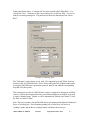
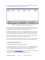
Using Query/Retrieve
Since the use of Q/R results in adding images to your system, it is located in the center
section of the main Database Browser panel of Metron.
Click on the button labeled “Q/R…” (or in some layouts “DICOM Q/R…”)
The top portion of the panel lets you select the server you wish to pull images from, and
to describe the query you will use to hunt for images on that server.
Check one or more of the query criteria and enter values (usually with “*” for wildcard)
It is recommended to use the “*” character as a wild-card unless you know the exact
value used on the remote system for patient name, or other criteria. You can query on one
or more of:
1) Patient Name
2) Patient ID
3) Study ID
4) Date of the Study
After setting up your criteria, click on “Query Server”. After a short delay a list of all
studies on the remote system matching your criteria will be displayed. If you don’t see
what you are seeking, just alter your query keys, and click “Query Server”’ again.
Metron-MD User Manual
Version 7
© EponaTech LLC, 2013
56
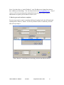
To retrieve one of the displayed studies back to your local Metron, click on that study to
highlight its line in the list. At the bottom of the panel, you will see how Metron will
extract the storage names from the DICOM tags. You can alter the source of these tags
with the three associated pull-down menus to try to extract these names as you would like
to see them in Metron.
Click the “Retrieve” button to commence the retrieval of the study images.
A study is selected, criteria for determining storage names selected,
and retrieval is underway.
As soon as the retrieval has commenced, you are free to leave this panel and do other
activities in Metron while the images are fetched. You can even exit Metron and they
will still be fetched (of course, the computer must stay on and connected to the internet).
Metron’s Q/R feature is “study based” – you query for a list of studies, and you may
decide to retrieve a study. There is not a way to only retrieve a subset of the images in the
study – it is always the full study that is retrieved.
Metron-MD User Manual
Version 7
© EponaTech LLC, 2013
57
At any time, you may click on the “Receive Images” button in Metron’s main Database
Browser panel to see the status of your retrieval operation.
The “Receive Images” panel shows a log of images that have come into Metron via
DICOM, including those retrieved as part of a Q/R action.
If the retrieval animation is running, it means Metron is running the retrieval process in
the background. New lines will appear in the log as images arrive at Metron. You can
go look at them, and return to this panel later to again check progress.
Depending on the kind of remote server you are retrieving from, and how you have your
copy of Metron configured, the retrieved images might show up as “Pending” (causing
the “Receive Images” button to blink), or they might be “Auto-Imported” directly into
your local Metron database (which does not cause the “Receive Images” button to blink,
but does leave a line in the log seen in the Receive Images panel).
In the “DICOM Preferences” panel under the “DICOM Receive” tab, it may be possible
for you to set up an auto-import rule for DICOM images arriving from a Q/R transfer.
Troubleshooting Query/Retrieve
1. I can Query but Retrieve does not return any images
Most likely the remote server has not been set up to “know” about your Metron and so it
is not allowing the unknown system to pull images from it. The administrator of the
remote system has to set it up to “know” about your Metron. What they need is:
1) Your IP address (use www.ipchicken.com to get your IP address if you don’t know it)
2) Your Port (Metron listens on port 4002 by default)
3) Your AE title (Metron is known as METRON_AE by default)
Metron-MD User Manual
Version 7
© EponaTech LLC, 2013
58
Note: if you don’t have a “static IP address”, your IP address may change from time to
time without your knowledge. You can always check with www.ipchicken.com --- but of
course it will be inconvenient to be continually having to ask the remote system’s
administrator to update your IP address in their server.
2. Retrieve gets stuck and never completes
You can stop an active retrieve operation in Metron by going back to the Q/R panel and
clicking on the “Retrieve” button. It will tell you that a retrieve is underway, and will
offer to let you stop it.
Click “Retrieve” while Metron is retrieving, and you can kill the retrieve.
Metron-MD User Manual
Version 7
© EponaTech LLC, 2013
59
8. DICOM Print
DICOM Print is supported as of release 6.07.
Configuring DICOM Print
In the DICOM Preferences panel there is a tab for DICOM Print:
Initially DICOM Print will not appear in Metron’s user interface until it is turned on by
checking the box at the top of the DICOM Print Preferences page:
Metron-MD User Manual
Version 7
© EponaTech LLC, 2013
60
You should then choose which DICOM Printer you will be using from the pull-down.
These names refer to text files that specify the capabilities of a given printer. These files
reside in C:/Epona/DP/Desc and if you open the one for Fuji-DryPix-1000 it’s contents
are:
[Fuji-DryPix-1000]
Aetitle = PRINTER_AE
Description = Fuji-DryPix-1000
Hostname = localhost
Port = 4008
Type = LOCALPRINTER
BorderDensity = 150\20\BLACK\WHITE
DisableNewVRs = false
DisplayFormat=1,1\1,2\2,2\2,3\3,3\3,4\3,5\4,4\4,5
EmptyImageDensity = 20\BLACK\WHITE
FilmDestination = MAGAZINE\PROCESSOR\BIN_1\BIN_2
FilmSizeID = 8INX10IN\10INX14IN
ImplicitOnly = false
MagnificationType = REPLICATE\BILINEAR\CUBIC\NONE
MaxDensity = 320
MaxPDU = 32768
Metron-MD User Manual
Version 7
© EponaTech LLC, 2013
61
MediumType = PAPER\CLEAR FILM\BLUE FILM
MinDensity = 20
OmitSOPClassUIDFromCreateResponse = false
PresentationLUTMatchRequired = false
PresentationLUTinFilmSession = false
ResolutionID = STANDARD\HIGH
SmoothingType = NONE
Supports12Bit = true
SupportsDecimateCrop = true
SupportsImageSize = true
SupportsPresentationLUT = true
SupportsTrim = true
Important! You must edit the lines in the first section of this file in order
to give the AEtitle, the Hostname, and the Port of your actual DICOM
Printer.
Other entries in this file may be edited if you think that it does not accurately describe this
printer. Other files in this same format may be added to this folder to define other
DICOM printers.
At present, the only selection under “Options” is the “Default” choice. In the future, we
will have more flexibility by adding some optional inputs to the printing.
Metron-MD User Manual
Version 7
© EponaTech LLC, 2013
62
Using DICOM Print
DICOM Print is in the multi-image print interface familiar to Metron users.
First highlight the thumbnails corresponding to the images you wish to print (remember
the “All” button is helpful if printing all images of a study). Then click the “Print” button
at the bottom of the Study List screen:
Metron-MD User Manual
Version 7
© EponaTech LLC, 2013
63
Choose the number of images you wish to print per page. Indicate if you want
Annotation and/or Mark-up to be shown on the images. Then click “DICOM Print”.
The printing will be sent to the printer.
Problems
If the images do not print, please send us the log file at:
C:/Epona/DP/LOG.TXT
Metron-MD User Manual
Version 7
© EponaTech LLC, 2013
64
Appendix B: Setting up Automatic Image Rotations
For most DR systems and some CR systems that Metron supports, there is a way to assign
a rotation to the image when it is acquired. For small-animal systems, usually the animal
is viewed across the screen, but for DV and VD shots, it is customary to have the body
oriented up-and-down on the screen. For this and other reasons, we need a way to rotate
images in an automatic fashion depending on the anatomy and the view taken. For equine
systems, the required view rotations can become elaborate.
The "<Platform>ViewRotations.txt" File
Here is how to assign automatic image rotations. It is done in a file which sits in:
C:/Epona/Databases/Main
and the file is called (depending on the system) one of these:
SamsungViewRotations.txt
RpanelViewRotations.txt
or maybe another name. Please ask EponaTech if you can’t find the file name for your
hardware.
Here is an example of the contents of the "<Platform>ViewRotations.txt" file for an
equine system:
VERSION = 1.0
Default =-90
*,DP,RF,90
*,DP,RR,90
*,Lateral,LF,90
*,Lateral,LR,90
Head,*,*,0
The idea is this: in the second line I give the "Default Rotation" which is applied to all
images unless the default is overridden in a following line in the file. So, the current
default is -90. To understand it you have to know where "zero" is.
Each line of the file can specify the rotation to use instead of the default for a given
Region, View, and Limb.
Metron-MD User Manual
Version 7
© EponaTech LLC, 2013
65
For example, if you put in the line
Foot,Lateral,RF,90
it would use a 90-degree rotation for the Right Front lateral of the Foot.
Then, Metron is set it up so that "*" (asterisk) is the "wild card". So in the current file,
the line
*,DP,RF,90
Means that the DP view of ANY region for the RF will be 90. So, this works for Foot,
Pastern, Fetlock, Cannon -- in fact every shot that has a view called "DP".
You see later in the file I have
Head,*,*,0
Meaning that any view of the head, I think we want an image wider than tall, so we use
rotation = 0 (which happens to be the correct number for one certain panel – it may not be
for yours)
The only values of rotation you can give are 0,90,-90,180
You have to use "RR" and "LR" for hind limbs ( not "RH" and "LH" )
Finally, you want to keep this list (the number of lines in the file) as short as possible simplicity is good - the system searches down this list after each shot to check if the shot
should be rotated or not, so its best if the list is not hundreds of lines long.
(Note: if you look at the default values in "SamsungViewRotations.txt" (which is for
equine) you will see a rather complete example of 'good settings' for an equine system).
DENTAL
Similar files exist for DR Dental systems, e.g. "DRDentalViewRotations.Accent.txt"
They are essentially only used for flipping the image by 180 depending if in the "Right"
side or the "Left" side of the mouth.
Metron-MD User Manual
Version 7
© EponaTech LLC, 2013
66
Appendix C: Image Stitching in Metron-MD
Image stitching is available in Metron-MD so that two or more images can be joined together
into a single image. This is a purely manual process and it is up to the Metron user to align
images and then to store the stitched image.
First the Metron user must take two or more images that are nearly equally exposed and that are
suitable for stitching. In this example, we use an image of a hand and forearm (Figure 1), along
with a second image of the forearm and elbow (Figure 2).
Figure 1. First image.
Metron-MD User Manual
Version 6
© EponaTech LLC, 2011
67
Figure 2: Second image.
The original images have been acquired and are in the same study in Metron (Figure 3).
Figure 3: Two images, suitable for stitching, in the same study in Metron-MD
The user begins by selecting two (or more) images by clicking to highlight them, and then clicks
on the “Stitch Images” button (Figure 4).
Metron-MD User Manual
Version 6
© EponaTech LLC, 2011
68
A new “Stitch Images” panel is presented (Figure 4). The “Stitch Images” panel has several
controls on the right hand side which allow the user to drag and position images, rotate them,
scale them, trim them, etc.
Figure 4: The “Stitch Images” panel.
The user begins by clicking on an image and dragging it with the mouse. The “palette” enlarges
as needed as images are dragged on the screen. In Figure 5 a rough initial positioning has been
done by just dragging the image of the hand.
Figure 5: User has dragged the image of the hand to the left side of the area.
Metron-MD User Manual
Version 6
© EponaTech LLC, 2011
69
In this example, the user now sees that the left image (hand and forearm) must be rotated slightly
in the clockwise direction. Since this image is highlighted in red, it is the “active image” which
the tools on the right hand side of the panel will control. So, the “Fine Rotation” buttons are
used to rotate this image as shown in Figure 6.
Figure 6: The user has rotated the left hand image (hand and forearm) into alignment with the forearm
portion of the second image. This rotation can be further tuned
when the images are slid together.
The user drags the left image on top of the right hand image, and uses the “Fine Jog” buttons in
the panel to carefully position it into alignment (Figure 7). Other options available to the user
were not required in the case of these two images (options such as “scale” to enlarge one image
relative to other, trim options to trim edges, push/pop to control which image is “on top”, etc).
Figure 7: The user uses the “Fine Jog” buttons (red colored arrows) to carefully jog
the image into position.
Metron-MD User Manual
Version 6
© EponaTech LLC, 2011
70
Figure 8: The red highlight box around the “active image” can be temporarily turned off so the user can
see exactly how the stitch will look.
Satisfied with the alignment of the images, the user clicks the button labeled “Stitch Done, Add
to Study”, and the stitched image is added to the study (Figure 9). The original two images are
not disturbed.
Figure 9: Stitch is complete. This image may now be used in Metron just like any other image.
Metron-MD User Manual
Version 6
© EponaTech LLC, 2011
71
The final stitched image is shown in Figure 10.
Figure 10. The final, stitched image. The stitch line is apparent because the two X-Ray exposures
were not the same in this exam.
Metron-MD User Manual
Version 6
© EponaTech LLC, 2011
72
Appendix D: Guided Mark-Up in Metron-MD
Example: Measurements for the Lateral Radiograph of the Lumbar Spine
Guided Mark-Up is provided for certain radiographic views for which current practice has well
defined measurements. The guided mark-up process prompts the user to pick key points in the
image from which these measures are computed.
The guided mark-up process will be illustrated by the example of measurements for the lateral
radiograph of the lumbar spine as shown in Figure 1.
Figure 1. Lateral Lumbar Spine Radiograph
The process starts by acquiring the image, labeling the anatomy by selecting the appropriate
region on the anatomy chart, and clicking the “Guided Mark-Up” button (Figure 2).
Figure 2. Select the “Guided Mark-Up” Tool
Metron-MD User Manual
Version 6
© EponaTech LLC, 2011
73
A new panel for the “Guided Mark-Up” process (the “Guide Panel”) is presented on the right
side of the screen (Figure 3), where instructions are presented. The user works on the actual
radiograph on the left side of the screen, picking points etc., following the instructions on the
Guide Panel.
Figure 3. Screen shot after the Guided Markup button is pressed.
Metron-MD User Manual
Version 6
© EponaTech LLC, 2011
74
On the Guide Panel (Figure 4), step-by-step instructions that instruct the user which points to
pick in the radiograph are shown near the top of the window. Here, the user is instructed to pick
2 points on the posterior body of each vertebra from L5 to T12.
An Instructional Image is displayed at the center of the Guide Panel. There are red boxes on the
Instructional Image that indicate where the user should pick the points on the actual radiograph.
The Instructional Image is NOT the actual radiograph in question. Rather, it is a fixed “sample
radiograph” just used as part of the instructions to show where to pick the points. There is a new
Instructional Image for each step of the process showing which points to pick in that step.
Note that if anything is obscured or difficult to pick during any step of this process, the user may
indicate this fact by selecting the box labeled “Feature unclear, and “These picks are guesses,””
which box is near the bottom of the Guide Panel. If this selection is made, the procedure
continues, but the measurements resulting from these picks will be highlighted in a blue font so
that the user is reminded that they may not be fully accurate.
Instructions
Instructional Image
Figure 4. Guide Panel for Step 1
Metron-MD User Manual
Version 6
© EponaTech LLC, 2011
75
The user uses his medical judgment to pick the actual points in the actual image on the left side
of the screen (Figure 5). As the user picks the points, small red squares are overlaid on the image
to show the points that have been picked. These selected points may be “dragged” with the
mouse so that the user can be sure to position them where he wishes.
Figure 5. Step 1 of the lumbar spine picking mark-up in progress.
This image shows this task after the user has selected 6 points.
Metron-MD User Manual
Version 6
© EponaTech LLC, 2011
76
When the requested number of points have been picked by the user, a green curve is displayed
that is constructed from these points (Figure 6). In guided mark-up, the appearance of green
overlaid graphics always indicates that the picks are complete for the current instruction step.
Figure 6. The picks for “Step 1” of the guided mark-up have been completed.
Metron-MD User Manual
Version 6
© EponaTech LLC, 2011
77
The user then clicks on the “Next Step>>” button in the Guide Panel to advance to the next step,
Step 2, and the user is instructed to select the two “superior” points on S1, the Sacrum. (Figure
7). When the user has picked the two points on the sacrum in the actual radiograph, a green line
is drawn on the radiograph, which signals the user that he has completed this step (Figure 8).
Figure 7. Guide Panel for Step 2, pick two superior points on S1.
Figure 8. Step 2 is completed.
Metron-MD User Manual
Version 6
© EponaTech LLC, 2011
78
Again, when the user clicks on “Next Step>>,” the process advances to Step 3, and the user is
instructed to pick the “anterior inferior” point on the L5 (Figure 9). Since this step of the
instructions calls for just a single point being picked, it is immediately highlighted in green after
the user has selected the point on the radiograph, indicating that the user has completed this step
(Figure 10).
Figure 9. Guide Panel for Step 3, pick anterior inferior point on L5.
Figure 10. The user has selected the requested point.
Metron-MD User Manual
Version 6
© EponaTech LLC, 2011
79
In the next step, Step 4, the user is instructed to pick 2 points on the anterior body of L3 (Figure
11).
Figure 11. Guide Panel for Step 4, pick 2 points on the anterior body of L3.
Figure 12. After the user selects the two points on the radiograph, a green line is
drawn between them to indicate that the requested picks are complete.
Metron-MD User Manual
Version 6
© EponaTech LLC, 2011
80
When the user clicks on “Next Step>>,” the Guide Panel for Step 5 is presented, which is the last
step in the guided mark-up of the lateral lumbar spine. The user is instructed to pick the two
points on the anterior of the T12 vertebra (Figure 13). When the user has selected the two points
on the radiograph, a green line is drawn to indicate that this step of the process is complete
(Figure 14).
Figure 13. Step 5, pick 2 points on the anterior body of T12
Figure 14. Step 5 is complete.
Metron-MD User Manual
Version 6
© EponaTech LLC, 2011
81
When the final points have been picked in the guided mark-up process, clicking the Next Step
button leads the user to a table of measurements that is made from these picks (Figure 15). The
small check-box to the left of each measurement name can be selected to display the
measurement overlaid on the image, so that the meaning of the measure will be clear to the user.
Figure 15: A table of computed measures. Clicking the check-box to the left of
the measure’s name will display it graphically on the image.
Metron-MD User Manual
Version 6
© EponaTech LLC, 2011
82
The Jackson’s Angle measurement is displayed when the user checks the checkbox next to
“Jackson’s Angle” (Figure 16).
Figure 16. Example showing “Jackson’s Angle” displayed on the image. This
is a well known measure which is the angle between lines constructed from
the posterior sides of the L5 and L1 vertebrae.
Metron-MD User Manual
Version 6
© EponaTech LLC, 2011
83
The Lumbar Dordosis measurement is displayed when the checkbox next to “Lumbar Lordosis”
is checked (Figure 17).
Figure 17. This example shows the lumbar lordosis overlaid on the image. It is an
angle related to the top of the sacrum and the bottom of the T12 vertebra.
Metron-MD User Manual
Version 6
© EponaTech LLC, 2011
84
A user may check multiple checkboxes and have multiple measurements overlaid on the
radiograph. Figure 18 shows the radiograph when the checkboxes for L1-2 Angle, L2-3 Angle,
L3-4 Angle, and L4-5 Angle are checked.
Note that the guided mark-up process gives the practitioner a guide to pick certain key anatomy
points in order to compute well-known measures. It is merely the presentation of simple picking
instructions to the user so that these measures can be made in a standard way. The guided markup process itself is objective – no judgments are made regarding what these values “should be” in
a healthy, normal individual.
Figure 18. In this image, four of the check-boxes have been checked so that the
relative angles between these vertebrae are all displayed on the image.
Metron-MD User Manual
Version 6
© EponaTech LLC, 2011
85
Metron does offer the ability for the physician to enter a set of “zones” which describes desirable
ranges for each of these measured parameters. These ranges are entered by the physician if they
wish to use this feature. While the measurements made by guided mark-up are standard and
known to medical practitioners (in this case, chiropractors), there is not always agreement on
what the “normal and healthy” values should be. Because of this disagreement among
practitioners, Metron does not prescribe these “normal ranges” but gives the physician the ability
to enter the ranges that they believe in. In Figure 19 we show the zones panel for a set of
desirable ranges entered by the physician user of Metron.
Figure 19. Once the user has entered desirable ranges and saved them as a set of “zones”,
Metron will display each parameter alongside its desirable range, and this line will
be highlighted in red if the value (from the current image) falls outside this range.
Metron-MD User Manual
Version 6
© EponaTech LLC, 2011
86
Figure 20. The “Edit” button next to each parameter can be used to edit the
“desirable range” used in the set of zones. The user may also assign an “importance”
as Low, Medium, or High, to each measure. These importance values are not used in
any computation, but merely as notes to the practitioner.
Metron-MD User Manual
Version 6
© EponaTech LLC, 2011
87
Figure 21. If a user edits the desirable ranges for one or more measures,
the “Save Zones” button may then be used to save this new set of desirable
ranges as a set of “zones” which can then be used for future patients.
Metron-MD User Manual
Version 6
© EponaTech LLC, 2011
88