1
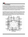
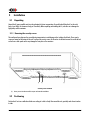
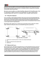
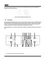
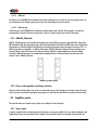
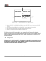
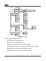
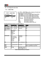
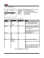
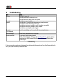
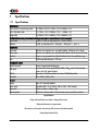
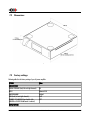
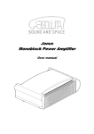
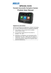
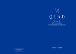
A1 Power Amplifier
User Manual
Dear Client,
We are honored that you have chosen the CH A1 Power Amplifier. Our team has put all his efforts into designing and
manufacturing this top quality versatile and future-proof product and is proud to present it to you. We hope your A1 will bring you
uncountable hours of emotion from your musical collection.
But before starting your musical journey, we kindly ask you to pay attention to the information contained in this manual. The A1,
as you will discover in the following pages, is a Swiss precision product designed for ultimate performance and flexibility. However,
reaching sonic excellence requires your unit to be setup and operated correctly and this what this manual is all about. If you have
any questions or require assistance, please don't hesitate to contact your authorized dealer.
We hope you will enjoy your A1 amplifier for many years.
The Concert has just begun...
Cossy F.
Heeb T.
FCC-Notice
Note: This equipment has been tested and found to comply with the limits for a Class B digital device, pursuant to Part 15 of
the FCC Rules. These limits are designed to provide reasonable protection against harmful interference in a residential
installation. This equipment generates, uses and can radiate radio frequency energy and, if not installed and used in
accordance with the instructions, may cause harmful interference to radio communications. However there is no guarantee that
interference will not occur in a particular installation.
If this equipment does cause harmful interference to radio or television reception, which can be determined by turning the
equipment off and on, the user is encouraged to try to correct the interference by one or more of the following measures:
•
adjust or relocate the receiving antenna
•
increase the separation between the equipment and the receiver
•
connect the equipment into a mains outlet on a circuit different from that to which the receiver is connected
•
consult the dealer or an experienced ratio/TV technician for help
Disposal – Environmental care
Directive 2002/96/EG of the European Parliament requires consumer electro-technical appliances to be
disposed separately and have to be indicated with the following symbol. Should you dispose this
component please do so in conformity with local and global legal and environmental regulations and
according to best practices. We strongly encourage you to recycle any batteries used with this component.
Table of contents
1 Technical Highlights.............................................................................................................................................................. 8
1.1 Unmatched flexibility.................................................................................................................................................. 9
1.1.1 Operation modes................................................................................................................................................ 9
1.1.2 Feedback control ............................................................................................................................................. 10
1.1.3 Gain control..................................................................................................................................................... 10
1.1.4 Bias adjustment................................................................................................................................................ 10
1.2 Advanced monitoring circuit....................................................................................................................................... 10
1.2.1 Power monitoring............................................................................................................................................. 10
1.2.2 Temperature monitoring.................................................................................................................................... 11
1.3 Mechanical construction............................................................................................................................................. 11
1.4 Modular architecture and slot-in boards...................................................................................................................... 11
1.4.1 Monaural analog inputs: ANALOG_IN board....................................................................................................... 12
1.4.2 Firmware update and control: CONTROL board.................................................................................................... 12
1.5 Power supply............................................................................................................................................................ 12
2 Before Use........................................................................................................................................................................ 13
2.1 Package content........................................................................................................................................................ 13
2.2 Safety notice............................................................................................................................................................. 13
2.3 User Manual............................................................................................................................................................. 14
2.4 Mains supply............................................................................................................................................................. 14
2.5 Transport and packaging............................................................................................................................................ 14
2.6 Cleaning................................................................................................................................................................... 15
2.7 Maintenance and service............................................................................................................................................ 15
3 Installation........................................................................................................................................................................ 16
3.1 Unpacking................................................................................................................................................................ 16
3.1.1 Removing the security screws............................................................................................................................ 16
3.2 Positioning................................................................................................................................................................ 16
3.2.1 Unit position adjustment.................................................................................................................................... 17
3.2.2 Adjustment shaft covers.................................................................................................................................... 17
3.3 Connections............................................................................................................................................................... 18
3.3.1 CONTROL board................................................................................................................................................ 19
3.3.1.1 USB port.................................................................................................................................................. 20
3.3.1.2 Ethernet port........................................................................................................................................... 20
3.3.2 ANALOG_IN boards.......................................................................................................................................... 20
3.3.3 Power cord receptacle and voltage selection....................................................................................................... 20
3.4 Amplifier modes........................................................................................................................................................ 20
3.4.1 Stereo mode..................................................................................................................................................... 20
3.4.2 Mono bridged mode.......................................................................................................................................... 21
3.4.3 Left or Right Mono mode................................................................................................................................... 21
3.4.4 Passive bi-amplification mode............................................................................................................................ 22
3.4.5 Active bi-amplification mode............................................................................................................................. 22
3.4.6 Chained mode.................................................................................................................................................. 23
4 Operation.......................................................................................................................................................................... 24
4.1 Front panel controls................................................................................................................................................... 24
4.1.1 Front panel...................................................................................................................................................... 24
4.1.2 Front face push-buttons..................................................................................................................................... 24
6
A1 User Manual
Rev 1.2
4.2 Operating modes....................................................................................................................................................... 25
4.2.1 Normal mode................................................................................................................................................... 25
4.2.2 Shortcuts.......................................................................................................................................................... 27
4.2.3 Menu mode...................................................................................................................................................... 29
4.3 Configuration............................................................................................................................................................ 31
4.3.1 A1 configuration menu items............................................................................................................................. 33
4.3.1.1 AUDIO SETTING........................................................................................................................................ 33
4.3.1.2 DISPLAY SETTING...................................................................................................................................... 34
4.3.1.3 SHORTCUTS.............................................................................................................................................. 35
4.3.1.4 FACTORY SETTING..................................................................................................................................... 36
4.3.1.5 INSTALLED OPTIONS................................................................................................................................. 36
4.3.1.6 NETWORK................................................................................................................................................ 37
4.4 Returning to Factory defaults..................................................................................................................................... 37
5 Firmware update............................................................................................................................................................... 38
5.1 Introduction.............................................................................................................................................................. 38
5.2 Firmware Update procedure....................................................................................................................................... 38
5.2.1 Preparing the firmware image........................................................................................................................... 38
5.2.2 Updating the firmware (Firmware Update procedure)......................................................................................... 39
5.2.3 Emergency Firmware Update procedure............................................................................................................. 39
6 Troubleshooting................................................................................................................................................................. 41
7 Specifications..................................................................................................................................................................... 42
7.1 Specifications............................................................................................................................................................ 42
7.2 Dimensions............................................................................................................................................................... 43
7.3 Factory settings......................................................................................................................................................... 43
Rev 1.2
A1 User Manual
7
1
Technical Highlights
CH products are proudly designed and manufactured in Switzerland by CH Precision Sàrl. Our engineers have put all their knowhow into bringing you the A1, a top performances future-proof modular two output channels power amplifier with USB flash-drive
firmware update and Ethernet control capabilities. As all CH Precision products, the A1 is highly versatile: a single A1 can be used
as a stereo power amplifier (with two mono input boards), or a pair of A1 can be used as mono power amplifiers. Even in
monaural mode, 4 setups are possible: left /right mono mode (the transformer of each A1 is dedicated to a loudspeaker, but only
one output board is used), bridged mode (to nearly quadruple the available power per channel), passive bi-amp (each channel
powers a specific speaker driver) or active bi-amp (when an active crossover network is placed between the preamplifier and the
A1). Moreover, multiple A1s can be chained for ultimate performance, using multiple A1s per speakers.
For increased flexibility, the A1 also provides two unique features: global/local feedback ratio and gain adjustments. The amount
of global feedback in the amplifying loop of each channel can be adjusted to best match virtually any speaker on the market. The
amplifier gain can also be adjusted over a 24 dB wide range, by 0.5 dB steps. This also greatly helps in matching the output level
of the preamplifier, the efficiency of the connected loudspeakers and the listening room. Three standard input connectors are
available (balanced XLR, single-ended RCA and BNC). Unbalanced inputs can be configured as high impedance input, or a 300
Ohm load can be engaged to match the output of 50 or 75 Ohm D/A controllers or preamplifiers. A pass-through XLR line-level
output is also provided for daisy-chaining multiple A1s.
(1)
(2)
(3)
(3)
(4)
(5)
(2)
(1)
(6)
(6)
(7)
(7)
(8)
(8)
(9)
(9)
(8)
(8)
(6)
(6)
(11)
(12) (16)
(15) (14) (13)
(12)
(11)
(10)
A1 main components
8
A1 User Manual
Rev 1.2
(1)
(2)
(3)
(4)
(5)
(6)
(7)
(8)
(9)
(10)
(11)
(12)
(13)
(14)
(15)
(16)
Output coil for HF immunity
Argento Audio speaker terminals
Monaural analog input boards (each A1 can be equipped with 1 or 2 such boards)
Mains switch and power cord receptacle
USB (firmware update) and RJ-45 (control) board
Adjustment shafts and screws
Power supply regulation boards
Overheat regulation fans
Heatsink-mounted monaural amplifier boards
User interface buttons
Rectifying diode bridges, mounted onto the front panel
Custom Mundorf rectifying capacitors
Main analog ground oxygen-free copper plate
AMOLED display (on front panel)
Standby power transformer (ensures green mode Standby)
Main power transformer
1.1 Unmatched flexibility
The A1 offers unmatched system integration flexibility. Not only does it provide multiple modes of operation (stereo, mono,
bridged and active or passive bi-amp) but is also provides adjustments to match speaker impedance and sensitivity through
feedback and gain controls. Operating modes can be selected by the user from the A1's front panel. In addition, multiple A1s can
be daisy-chained for ultimate performance in multi-amplification systems.
1.1.1 Operation modes
The A1 integrates two power amplification channels and provides the option to support a single or dual input boards. In its default
configuration, the A1 is delivered with a single input board and provides following modes of operation:
•
Bridged Mono Mode: In this mode, the A1 operates as a very high power mono power amplifier, where both
amplification channels are used in balanced mode for a single audio channel. When configured in Bridged Mono Mode,
the A1 can deliver up to 350 W under 8 Ohm. It is optimal for high impedance speakers in large rooms, requiring large
voltage swings.
•
Left or Right Mono Mode: In this mode, the entire power of the transformer is dedicated to a single output channel. In
Left or Right Mono Mode, the A1 can deliver 550 W under 1 Ohm. It is optimal for low impedance speakers, requiring
large amount of current.
•
Passive Bi-Amp Mode: In this mode, the A1 operates its two power amplification stages in parallel, each channel driving a
different speaker terminal with the same signal. Feedback and gain can be adjusted independently for each channel to
best match the individual speaker sections. In Passive Bi-Amp Mode, each channel delivers 100 W under 8 Ohm. It is
optimal with speakers with more than one binding post pair on its passive crossover filter network.
By adding a second input board, the A1 provides following additional operating modes:
•
Rev 1.2
Stereo Mode: In Stereo Mode, each amplification stage is driven by its dedicated input board and the amplifier operates
A1 User Manual
9
as a standard stereo power amplifier. Feedback and gain settings are shared among both amplification channels and the
A1 delivers 100 W under 8 Ohm per channel. It is the configuration used when a single A1 drives a pair of speakers.
•
Active Bi-Amp Mode: As for Stereo Mode, Active Bi-Amp Mode links each amplification stage to its dedicated input board.
Feedback and gain can however be adjusted individually for each channel in order to best match the requirements of
each driver. An active cross-over is generally used to split the signal into different frequency bands between the system
controller/preamplifier (such as CH Precision's C1) and the power amplifiers. In the Active Bi-Amp Mode, the A1 delivers
100 W under 8 Ohm on each channel. It is optimal if the speaker has an external active crossover filter network.
1.1.2 Feedback control
One of the A1's most unique features is its user controllable feedback. This feature provides control over the ratio between global
and local feedback applied in the A1's amplification stage. Global feedback takes a portion of the output signal after the power
stage and feeds it back to the input of the amplifier. This ensures a very low output impedance and low distortion figures. Local
feedback, on the other hand, does not include the output stage and lets the latter operate in open loop mode. This favors small
signal details and timing. As a rule of thumb, a higher ratio of global feedback is preferred for grip and control in the low
frequencies whereas a lower ratio is preferred for speed and details in the high frequencies. This rule is however not absolute as
each speaker and cross-over are different and we highly recommend to try out various settings to find the best match with the
connected loudspeakers, especially if the A1 is driving a complete full bandwidth loudspeaker. In multi-amplification systems,
different feedback settings are commonly used for the various speaker sections opening a whole new level of performance. We
recommend to start with pure local feedback and increase the global feedback until the bass are tight enough for your personal
taste. Feedback settings can be adjusted on the fly from the A1's front panel.
1.1.3 Gain control
The A1 provides an integrated gain control with a 24 dB range and 0.5 dB steps. This gain control allows for optimal matching of
speaker sensitivity, room size, and preamplifier output level. In multi-amplification systems it can be used to match the sensitivity
of the individual speaker sections. Gain is conveniently accessed by a front panel control and can be set on the fly.
1.1.4 Bias adjustment
The A1 provides an advanced bias control circuitry that not only follows slow temperature variations, but also accurately takes into
account all the dynamic aspects induced by transients in the musical content.
1.2 Advanced monitoring circuit
1.2.1 Power monitoring
Each power amplifier board is equipped with a DSP that monitors the instantaneous voltage and current output of each A1's
channel. Both values are sampled at around 100 kHz, ensuring peak values are properly detected. This circuitry has several
purposes: give the user a feedback of the peak power fed to the speakers, and detect malfunctions such as short-circuits,
disconnected speakers or amplifier damage.
10
A1 User Manual
Rev 1.2
1.2.2 Temperature monitoring
The DSPs are also responsible for reading both the power transistors and the radiators temperatures. If the temperature gets
excessive, the fans located underneath the radiator will start forcing a larger air flow to cool down the A1. If that is not sufficient
and the A1 keeps warming up, the class-A polarization is turned off, forcing the A1 to work in pure class-B. If removing the output
stage bias current is still not enough, and the temperature keeps rising, the A1 will protect itself by entering standby mode. Please
note that under normal conditions, none of the above should happen, except for the fans helping the A1 to cool down when used
at very high level.
1.3 Mechanical construction
The A1 power amplifier is assembled from high-quality aluminum and steel elements with no visible screws on the front, top and
side panels. The front panel, base, side panels and top cover are machined from aluminum. The power supply is based on a fully
shielded 1200 VA toroidal transformer and custom Mundorf rectifying capacitors sitting in the central position of the unit. Argento
Audio internal wiring is used throughout the unit and binding posts from the same manufacturer provide the best possible interface
to your speaker cables. The area where the air flows to cool down the amplifier is isolated from the rest of the A1, ensuring all
electronics are preserved from dust accumulation. Pin assembly of all chassis elements provides smooth joints between elements
while screws every 6cm ensures protection against electromagnetic interferences. First class mechanical and chemical surface
treatments provide the luxury finish of the A1.
Four steel feet support the unit. Each feet ends with a elastomer ring to sit on delicate surfaces but is also equipped with a height
adjustable steel spike to fine tune unit positioning. Horizontal adjustment is done with the provided screwdriver through the four
adjustment shafts accessible from the top of the unit. In addition to providing convenient horizontal adjustment from the top of the
unit, the shafts also serve as vibration evacuation channels for any stacked unit. Special shaft covers are provided to interface with
the spikes of the stacked unit. Any vibration from the upper unit is transmitted by the shaft cover to the shaft of the lower unit and
from there to the lower unit's feet or spikes, forming a privileged path for vibrations evacuation.
1.4 Modular architecture and slot-in boards
The A1 benefits from a fully modular architecture. It features separated sections for power rails, analog and digital power supplies,
front panel, signal routing and central host processor, monaural analog input boards and single channel amplification boards. This
modular architecture combined with the USB plug for firmware update allows for easy servicing and upgrade should one section
become faulty or obsolete.
The slot-in boards section consists in a vertically mounted mother board with optional boards plugged into it. Optional boards
provide audio functionality and connectivity to other equipment. There are two types of slot-in boards:
•
ANALOG_IN: provides mono single-ended RCA and BNC (both configurable as either high impedance or 300 Ohm
terminated) and balanced XLR analog audio input. One (left or right) or two (left and right) such boards can be fitted
into the A1. By default, the A1 is factory delivered with a single ANALOG_IN board.
•
CONTROL: provides a USB port for software upgrade and an Ethernet port for command. The CONTROL board is factory
mounted in each A1.
Rev 1.2
A1 User Manual
11
There are three slots in the A1. Two of them can be populated with a left ANALOG_IN and/or a right ANALOG_IN board. The last
slot is dedicated to the CONTROL board. Note that optional boards MUST be installed by a qualified technician. Failure to do so will
void any warranty.
1.4.1 Monaural analog inputs: ANALOG_IN board
The ANALOG_IN board features a user selectable mono analog input on three different connectors: single-ended RCA, single-ended
BNC and balanced XLR. Both the RCA and BNC inputs can be configured for high-impedance or 300 Ohms load. In addition to its
inputs, the ANALOG_IN board includes an XLR output providing a pass-through of the input signal.
1.4.2 Firmware update and control: CONTROL board
The CONTROL board is factory installed into the A1. It provides a USB port for software updates using a flash drive and an Ethernet
port for controlling the unit over a network.
1.5 Power supply
The power supply of the A1 is a linear supply with multiple independent local regulations. It is based on an oversized magnetically
shielded toroidal 1200 VA mains transformer. A secondary (also toroidal) transformer is used as Standby transformer to ensure
green Standby mode, meeting the latest energy saving regulations. Both transformers have static shields between primaries and
secondaries. They are mounted on a separate steel plate which is isolated from the main base steel plate by silent blocks.
Custom made Mundorf 4-poles capacitors are used for rectification. These capacitors exhibit exceptionally low ESR, high speed and
high capacitance, providing instantaneous response to current draws from the output stage.
Discrete (power-transistor and op-amp based) ultra low noise regulators are used throughout the power supply to ensure the purest
low noise DC feed possible to the different sections. The input stages of the power section are also fully regulated to avoid any
coupling distortion. A massive oxygen-free copper plate is used for signal ground.
Input AC voltage to the power supply can be set to 100V, 115V or 230V AC depending on your local mains voltage.
12
A1 User Manual
Rev 1.2
2
Before Use
Please read the following carefully.
2.1 Package content
Make sure that the package content is complete. If not, please contact your authorized dealer. Your package should contain:
•
A1 power amplifier with one (mono bridged or mono passive bi-amp modes only) or two input boards, depending on the
ordered configuration
•
Power cord
•
Accessory box
•
User Manual (this manual, located in the accessory box)
•
A1 power amplifier Service Booklet with warranty card (located in the accessory box)
•
Adjustment screwdriver (located in the accessory box)
•
4x adjustment steel spikes (located in the accessory box)
•
4x adjustment shafts steel stacking covers (located in the accessory box)
•
4x adjustment shafts aluminum top covers (located in the accessory box)
Please store the packaging material for future transportation. Check your A1 power amplifier for apparent damages. In case of
damage, please contact your authorized dealer. If your A1 power amplifier is still very cold from transport, please let it warm up to
room temperature in order to avoid condensation inside the unit.
2.2 Safety notice
Make sure to observe the following rules:
•
Install your A1 power amplifier on a stable base
•
Do not install your A1 power amplifier near water
•
Always handle with care. The A1 power amplifier is heavy, so have someone help you when moving it around
•
Do not expose the unit to any kind of liquid
•
Do not install in direct sun light or near any heat source such as radiators or other apparatus generating heat
Rev 1.2
A1 User Manual
13
•
Do not install in a confined space and make sure sufficient air can flow around the unit, including under the unit.
•
Never install your A1 power amplifier directly on a carpet or any soft material, as fresh air flow from openings under
the unit to the side apertures is required for proper cooling of the unit.
•
Do not operate under high ambient temperature (>40°C) or with extremely high humidity such as in humid cellars
•
Only use options and accessories specified or recommended by the manufacturer
•
Do not open the unit nor try to service it by yourself. Do not try to install any option board by yourself. Always refer to a
qualified technician for service, maintenance or upgrades. Failure to do so will void the unit's warranty
2.3 User Manual
Please read this manual carefully before making connections or operating your A1 power amplifier. After reading, store the
manual in an accessible place for future reference. If, after reading this manual, you feel unsure about how to make connections
or how to operate the unit, please contact your authorized dealer.
2.4 Mains supply
Make sure to use 3 terminals (phase, neutral and earth) power cords with ground conductor. Make sure that the mains voltage
selection of the unit matches your mains voltage.
Make sure your A1 power amplifier is disconnected from AC wall power in the following cases:
•
When making connections (it is also recommended to disconnect the rest of the system from AC wall power)
•
When cleaning
•
During thunder storms
•
When unused for a long period
2.5 Transport and packaging
The A1 power amplifier must always be stored in its original packaging for transportation. Doing so will ensure optimal level of
protection of your unit. Therefore, keep all the packaging material in a dry and clean place for future use.
In addition, the transformer base plate must be secured for transportation to avoid excessive constraints on the silent blocks
isolating the chassis from transformer vibrations. This is done by the insertion of three security screws on the bottom of the unit.
Failure to do so will void the warranty as it may cause the silent blocks to tear up and the heavy transformer module to move
inside the A1, resulting in severe damages to all A1 components. Do not forget to install these screws for transportation and to
14
A1 User Manual
Rev 1.2
remove them at installation of the unit in its new location.
Finally we recommend to remove the adjustment spikes and to put them into the accessory box for transportation. Indeed,
vibrations during transport may cause the adjustment spikes to move from their fully retracted position. There is risk of scratching
the installation base if the spikes are not fully retracted when installing the unit.
2.6 Cleaning
Use a soft, dry towel or cloth for cleaning. Never use any solvent or liquids as they may damage the surface treatment or
penetrate inside the unit.
2.7 Maintenance and service
The A1 power amplifier contains no user serviceable parts. Do not try to open, modify or repair your A1 by yourself. This will void
any warranty. Your A1 power amplifier must be checked by a qualified technician in any of the following cases:
•
The unit is not functioning properly
•
The mains cable or the power cord receptacle is damaged
•
The unit has been dropped to the floor or presents external damage
•
The A1 power amplifier has been exposed to liquids (such as rain) or unknown substances
Rev 1.2
A1 User Manual
15
3
Installation
3.1 Unpacking
Unpack the A1 power amplifier and store the packaging for future transportation. Be careful when lifting the A1 as the unit is
heavy (over 40kg). Get someone to help you if necessary. When unpacking and installing the A1, take care not to damage the
high quality surface treatments.
3.1.1 Removing the security screws
ᄃ
The transformer base plate must be secured during transportation to avoid damage to the isolating silent blocks. Three security
screws are located on the bottom of the unit. To remove the security screws, tilt the unit on its side and unscrew. Do not tilt the unit
on the front or back panels as this may damage the front plate or the connectors.
(1)
(1)
(1)
Security screw location
(1) Security screws. Must be mounted for transport and removed at installation
3.2 Positioning
Position the A1 unit on a stable base. Make sure cooling air is able to freely flow around the unit, especially under the unit and on
its sides
16
A1 User Manual
Rev 1.2
When used as a stereo power amplifier, or in a horizontal multi-amplification configuration (each A1 driving the same section of
both left and right channels) the A1 should be located close to its matching D/A controller or preamplifier with short modulation
cables (preferably using the XLR balanced input).
When used as a mono power amplifier or in a vertical multi-amplification configuration (each A1 driving different sections of either
left or right channel), we recommend to locate each A1 close to the loudspeaker it drives, using short speaker cables. The
recommended modulation cable to connect the A1 to its matching D/A controller or preamplifier is again a balanced XLR.
3.2.1 Unit position adjustment
The A1 power amplifier is equipped with height adjustable feet. More precisely, each feet has an internal height adjustable spike
which can be accessed with the provided adjustment screwdriver through the adjustment shafts. When delivered from factory, the
adjustment spikes are not mounted in the feet but are located in the accessory box. Remove the adjustment spikes from the
accessory box and put one into each adjustment shaft. Place the provided screwdriver into the adjustment shafts and turn clockwise
to secure the spikes and make the required adjustments.
When the spikes are fully retracted, the A1 sits on elastomer rings to protect the base. If the base on which the A1 is located is
fragile or should not be scratched, please make sure to use the optional CH support discs to protect the base.
( 1)
( 1)
( 2)
( 2)
( 2)
( 2)
( 3)
( 3)
( 3)
( 1)
( 1)
( 3)
( 4)
Adjustment shafts, feet and spikes
(1)
(2)
(3)
(4)
Adjustment shafts. Insert adjustment spikes and use screwdriver to secure and adjust individual feet spikes
Feet
Adjustment spike heads (when inserted into adjustment shafts)
Adjustment spike
3.2.2 Adjustment shaft covers
Once the position of the unit is adjusted, place the appropriate shaft covers on the four adjustment shafts. There are two types of
shaft covers delivered with your A1 unit. One type of shaft cover (stacking cover, made of steel) is used when different CH units
are stacked. This type of cover includes a receptacle to receive the corresponding spike of the unit placed just above. By doing so,
mechanical vibrations are optimally transmitted to ground and minimized inside CH units. The second type of shaft cover (top
cover, made of aluminum) can be used when units are not stacked or for the top unit when stacked. It covers the shaft and
provides a smooth finish to the top of the unit. Shaft covers are located in the accessories box delivered with your A1 unit.
Rev 1.2
A1 User Manual
17
Never stack any component other than CH's on your A1. Never use the aluminum shaft covers (top covers) when another CH
component is to be stacked on top of your A1.
Shaft covers (left: stacking cover, right: top cover)
3.3 Connections
This section provides information about how to connect your A1 power amplifier to your system. As the A1 is a modular design with
different optional boards, the description applies to the example configuration presented below. For details about how to integrate
you A1(s) in a specific setup, please refer to the Amplifier modes section of this user manual. If you don't feel secure with the
connections to be applied to your configuration, please contact your authorized dealer for assistance.
The example configuration is a stereo-ready (2 input boards) power amplifier. Your configuration could only contain a single input
board.
(1)
(2)
(19)
(18)
(3) (4)
(4) (5)
(6) (7)
(8)
(9)
ᄃ
(13)
(13) (17)
(16) (15)
(14) (13) (12)
(11)
(10)
A1 rear panel connections
(1) Argento Audio right positive (or bridged mono positive) speaker terminal
18
A1 User Manual
Rev 1.2
(2)
(3)
(4)
(5)
(6)
(7)
(8)
(9)
(10)
(11)
(12)
(13)
(14)
(15)
(16)
(17)
(18)
(19)
Ethernet port for command interface [CONTROL board]
Power on/off switch
Analog ground connectors. Bottom one can be connected to digital ground (Earth) using provided jumper
RCA single-ended analog input for right channel [Right ANALOG_IN board]
BNC single-ended analog input for right channel [Right ANALOG_IN board]
RCA single-ended analog input for left channel [Left ANALOG_IN board]
BNC single-ended analog input for left channel [Left ANALOG_IN board]
Argento Audio left positive (or bridged mono negative) speaker terminal
Argento Audio left negative speaker terminal
XLR balanced analog output (pass-through for A1 chaining) for left channel [Left ANALOG_IN board]
XLR balanced analog input for left channel [Left ANALOG_IN board]
Transportation security screws (to be removed once A1 is placed in its definitive position)
XLR balanced analog input for right channel [Right ANALOG_IN board]
XLR balanced analog output (pass-through for A1 chaining) for right channel [Right ANALOG_IN board]
Earth connector. Internally connected to digital ground
Power fuse and voltage selection and power cord receptacle
USB port for software upgrades. [CONTROL board]
Argento Audio right negative speaker terminal
The CONTROL board is mandatory in any A1 configuration and is always factory installed. Depending on arrangement of optional
boards in the A1's expansion slots, connector arrangement may slightly differ on your unit. Each A1 unit provides 2 expansion
slots, each supporting a monaural analog input (ANALOG_IN) board.
ANALOG_IN boards provides 3 monaural user-selectable analog input connectors (balanced XLR, single-ended high impedance (HiZ) / 300 Ohm RCA and BNC) as well as an XLR output monitoring the input signal. This output is used to daisy-chain multiple A1s
in multi-amplification systems.
Installation and removing of optional boards must be done by a qualified technician only. Do not attempt to install or remove any
optional board by yourself as this would void the unit's warranty.
3.3.1 CONTROL board
The CONTROL board is factory installed into the A1. It provides a USB port for software updates and an Ethernet port for controlling
the unit over a network. Following drawing shows the layout of the back panel of the CONTROL board:
CONTROL board back panel layout
Rev 1.2
A1 User Manual
19
3.3.1.1 USB port
The USB port on the CONTROL board is dedicated to the firmware update of the A1 unit. Do not use it for any other purpose. For
more information on unit firmware update, please refer to the corresponding section of this manual.
3.3.1.2 Ethernet port
The Ethernet port on the CONTROL board is dedicated to network based control of the unit. This functionality is currently not
implemented, thus leave the Ethernet port unconnected. A future A1 firmware release will provide this functionality.
3.3.2 ANALOG_IN boards
ANALOG_IN boards feature a user selectable mono analog input on three different connectors: single-ended RCA, single-ended
BNC and balanced XLR. The analog stage design is fully discrete and balanced. Both the RCA and BNC inputs can be configured for
high-impedance or 300 Ohms load, the later allowing for optimal signal transmission when connected to the outputs of 50 or 75
Ohm D/A controllers or preamplifiers. In addition to their inputs, ANALOG_IN boards include an XLR output providing a passthrough of the input signal. This output can be used to daisy-chain multiple A1s in multi-amplification systems for ultimate
performance. Balanced connections are recommended for optimal performance. Following drawing shows the layout of the
connectors on the ANALOG_IN boards:
ANALOG_IN panel layout
3.3.3 Power cord receptacle and voltage selection
Make sure that the voltage selection is set to the correct value with respect to the AC voltage in your location. Connect the power
cord to the power cord receptacle and plug the power plug to an AC wall outlet only after all other connections have been made.
3.4 Amplifier modes
This section describes most standard setups in which one or multiple A1s can be integrated.
3.4.1 Stereo mode
A single A1 equipped with two analog input boards can be used as a stereo power amplifier. This is the simplest configuration that
already allows to enjoy the unique sound of the A1 amplifier. The picture below shows how it should be connected in this case.
20
A1 User Manual
Rev 1.2
C1 D/A Controller
Balanced XLR cables
Right Speaker Binding Post
A1 Stereo Power Amplifier
Left Speaker Binding Post
Stereo mode
3.4.2 Mono bridged mode
A pair of A1s, each equipped with a single analog input board can be used as a pair of high power with high voltage swing
monoblocks. This configuration should be used when low efficiency high impedance speakers are used in large rooms to achieve
higher sound level than possible with a single stereo A1. This configuration also exhibits a better signal-to-noise ratio. The picture
below shows how they should be connected in this case.
C1 D/A Controller
Balanced XLR cables
A1 Right Mono Power Amplifier
Right Speaker Binding Post
A1 Left Mono Power Amplifier
Left Speaker Binding Post
Mono bridged mode
3.4.3 Left or Right Mono mode
A pair of A1s, each equipped with a single analog input board can be used as a pair of high power with very high current capability
monoblocks. This configuration should be used when low efficiency low impedance speakers are used in large rooms to achieve
higher sound level than possible with a single stereo A1. The picture below shows how they should be connected in this case.
Rev 1.2
A1 User Manual
21
C1 D/A Controller
Balanced XLR cables
A1 Right Mono Power Amplifier
Right Speaker Binding Post
A1 Left Mono Power Amplifier
Left Speaker Binding Post
Mono mode
3.4.4 Passive bi-amplification mode
A pair of A1s, each with a single analog input board installed, can be used in passive bi-amplification mode. In such a case, each
output board of each A1 feeds the speaker's drivers of a given frequency range. The main advantage of this configuration is the
possibility to set optimal global/local feedback ratio for the different frequency bands. The picture below shows how the A1s should
be connected in this case.
C1 D/A Controller
Balanced XLR cables
A1 Right Mono Power Amplifier
Right Speaker Binding Post
A1 Left Mono Power Amplifier
Left Speaker Binding Post
Passive bi-amp mode
3.4.5 Active bi-amplification mode
A pair of A1s, each with two analog input boards installed, can be used in active bi-amplification mode. In such a case, each output
board of each A1 feeds the speaker's drivers of a given frequency range. This configuration is optimal when an active crossover
network is used. Optimal global/local feedback ratio can be set for the different frequency bands. The picture below shows how
they should be connected in this case.
22
A1 User Manual
Rev 1.2
C1 D/A Controller
Balanced XLR cables
Right Channel Active Filter
LF Output
HF Output
Left Channel Active Filter
LF Output
HF Output
Input
Input
Balanced XLR cables
Balanced XLR cables
A1 Right Power Amplifier
Right Speaker Binding Post
A1 Left Power Amplifier
Left Speaker Binding Post
Active bi-amp mode
3.4.6 Chained mode
When more than one A1 is to be used to drive a single speaker, they can be chained. This allows for ultimate configuration taking
both advantage of the increased power available in bridged mode, and the flexibility provided by multi-amplification (optimal
feedback ratio setting for each frequency band). The picture below shows an example of such a chained configuration, namely a
passive bi-amp bridged mode.
C1 D/A Controller
Balanced XLR cables
A1 Left HF Bridged Power Amplifier
Balanced XLR cable
Balanced XLR cable
A1 Right HF Bridged Power Amplifier
Right Speaker Binding Post
Left Speaker Binding Post
A1 Right LF Bridged Power Amplifier
A1 Left LF Bridged Power Amplifier
Passive bi-amp bridged mode (chained A1s)
Rev 1.2
A1 User Manual
23
4
Operation
The A1 Power amplifier is operated from the front panel. Feedback to the user is provided by a high-definition AMOLED display
with customizable colors. Setup operations are exclusively handled from the front panel.
4.1 Front panel controls
4.1.1 Front panel
(1)
(2)
(3)
Front panel elements
(1) Standby LED
(2) Five user control push-buttons
(3) Display area (high-definition AMOLED display
The standby LED lights up when the unit is in standby. It is normally turned-off during operation. The LED can also be programmed
to remain on during operation if the display is turned off. The display is a high-definition AMOLED panel with very wide viewing
angle, high contrast and high brightness ensuring optimal reading comfort. The color and brightness of the display can be
configured according to user's taste.
4.1.2 Front face push-buttons
The push-buttons located on the front panel of the A1 are the main user input devices.
24
A1 User Manual
Rev 1.2
(1)
(2)
(3)
(4)
(5)
Front panel push-buttons
Button number
Button symbol
Description
1
S
Standby (long push) / Mute/Unmute (short push)
2
N
Up
3
R
OK
4
O
Down
5
Q
Cancel
Front panel push-buttons description
4.2 Operating modes
The A1 power amplifier has two main operating modes: Normal mode and Menu mode. Normal mode is mainly used to display
general status (such as power or temperature) of the A1 whereas Menu mode is used to configure the unit. The A1 also includes
Shortcuts for quick access to selected Menu mode items. Shortcuts are user programmable and most Menu mode items can be
selected as Shortcuts.
4.2.1 Normal mode
In normal mode, the A1 can be configured to display its general status, such as operating mode (stereo/mono), input
(XLR/BNC/RCA), feedback ratio, peak power and average temperature in a standard CH Precision manner (like in the D1 and C1).
It can also be set to display a peak-power vu-meter, or a temperature gauge of each output channel. When powered-on, the A1
starts in Normal mode. The status display looks as follows:
Rev 1.2
A1 User Manual
25
(1)
(2)
BALANCED XLR
(8)
B-CLASS
(3)
7
12 W
(4)
BI-AMP
GLOBAL FB: 0%/40%
(7)
23 C
(5)
(6)
Normal mode display elements
(1)
(2)
(3)
(4)
(5)
(6)
(7)
(8)
Input connector selected, and impedance termination.
B-CLASS is displayed if the A1 gets too warm and the Class-A polarization is turned off
Mute indication. If the 7 symbol is present, the output is muted
Meter level of instantaneous power. Gives an image of peak power fed to the load. Except for bridged mode, the maximum power (among the 2
channels of the A1) is displayed
Average temperature of the 2 output boards (in degrees Celsius).
Global feedback applied in the right channel output board (only displayed in bi-amp modes)
Global feedback applied in the left channel output board (bi-amp modes) or in both channels output boards (stereo or bridged modes)
Amplifier mode (stereo, mono, bi-amp or bridged)
Displayed elements depend on the installed optional boards and user settings. In the example above, the A1 is set as a biamplifying mono power amplifier, using its balanced XLR input connectors, running in class-B with its output muted (by the way, in
that case the power display should be 0 W). Its internal temperature is 23°C (which is not a temperature at which it can turn to
class-B mode). The left channel is only applying local feedback, while the right channel is applying a mix of 40% global feedback
and 60% local feedback.
Following table shows the actions of the front panel push-buttons in Normal mode.
Front face push buttons
Unit State
Unit Action
S, short push
STANDBY
Any other state
Wake from STANDBY
Mute/Unmute
S, long push
STANDBY
Any other state
Wake from STANDBY
Go to STANDBY
N
Any state
Enter Shortcuts mode
26
A1 User Manual
Rev 1.2
R
Any state
Enter Shortcuts mode
O
Any state
Enter Shortcuts mode
Q
Any state
No effect
Push-buttons actions in Normal mode
4.2.2 Shortcuts
The A1 amplifier is configured by a set of menus as described in the next sections. To allow quick access to the most frequently
used configuration menu items, the A1 offers the concept of Shortcuts. Shortcuts are fully programmable and the user may choose
any configuration parameter as a Shortcut. There are up to 6 user programmable Shortcuts. To learn how to program individual
Shortcuts, please refer to the SHORTCUTS menu item in the next section. For a list of Factory default Shortcuts, please refer to the
Specifications section.
Shortcuts are accessed from Normal mode by a push of the OK [R], UP [N] or DOWN [O] buttons on the front face. Additional
OK [R] push skips to the next Shortcut. The last Shortcut is always dedicated to entering the Menu mode (SETUP). On this last
Shortcut, an OK [R] push will return to Normal Mode and an UP [N] push will enter the Menu mode. The individual parameter
for a given Shortcut is modified using UP [N] or DOWN [O] buttons. If there is no user action for about 10 s the unit will revert
to Normal mode.
Following table shows the actions of the push-buttons for Shortcuts.
Front face push buttons
Unit State
Unit Action
STANDBY [S] Short Push
Any state
Mute/Unmute
STANDBY [S] Long Push
Any state
Go to STANDBY
UP [N]
Shortcuts (except last)
Last Shortcut (SETUP)
Modify parameter up (when available)
No action
OK [R]
Shortcut (except last)
Skip to next Shortcut
Last Shortcut (SETUP) or Exit Shortcuts mode (Normal mode)
after current Shortcut has
been modified
DOWN [O]
Shortcuts (except last)
Last Shortcut (SETUP)
Modify parameter down (when available)
Enter Menu mode
CANCEL [Q]
Shortcuts
Exit Shortcuts mode (Normal mode)
Push-buttons actions for Shortcuts
The GAIN Shortcut gives a good illustration of how to navigate a Shortcut screen. Navigating other Shortcuts is similar.
Rev 1.2
A1 User Manual
27
(1)
GAIN
(6)
(5)
F
D
(2)
+0.5 dB
(3)
0 dB
-0.5 dB
(4)
GAIN Shortcut display elements
(1)
(2)
(3)
(4)
(5)
(6)
Shortcut title (Parameter being adjusted, for other Shortcuts, title changes accordingly)
Arrow indicating UP button [N] if applies. The item below indicates the next parameter value (up direction)
Next Parameter Value if UP button [N] is pushed (parameter up)
Current Parameter Value
Next Parameter Value if DOWN button [O] is pushed (parameter down)
Arrow indicating DOWN button [O] if applies. The item below indicates the previous parameter value (down direction)
The last Shortcut (SETUP) is always the same and cannot be removed or altered. It gives access the Menu mode to access the
detailed setup of the unit.
(1)
DETAILED SETUP
EXIT
(2)
D
ENTER
(3)
(4)
SETUP Shortcut display elements
(1) Shortcut title. It indicates that Detailed Setup (Menu mode) can be entered at this stage
(2) Current value of the parameter. Default action is to exit (go back to Normal mode)
28
A1 User Manual
Rev 1.2
(3) Arrow indicating UP button [N]
(4) Next parameter value. If UP button [N] is pushed, the unit enters into Menu mode
4.2.3 Menu mode
The Menu mode allows for Configuration and Setup of the A1 power amplifier through a set of menus. Menu mode is entered from
the last Shortcut item (see above). From Normal mode, enter the Shortcut mode by pushing the OK [R] button. By successive OK
[R] button pushes, step to the last Shortcut item (DETAILED SETUP) and push the TOP [N] button once to enter the Menu mode.
Navigation in Menu mode is based on UP [N] and DOWN [O] buttons to select an item or to change a value. The OK [R] button
is used for validation and CANCEL [Q] to exit without saving.
Front face push buttons
Unit Action
STANDBY [S] Short Push
Mute/Unmute the unit
STANDBY [S] Long Push
Put the unit into Standby
UP [N]
Move to next menu item upward
OK [R]
Enter next menu level or Validate choice (save setting)
DOWN [O]
Move to next menu item downward
CANCEL [Q]
Return to previous menu level without saving
Push-button actions in Menu mode
Following illustration shows the elements of a the A1 SETUP Menu page, the entry point to the A1 menu structure.
(1)
A1 SETUP
AUDIO SETTING
DISPLAY SETTING
SHORTCUTS
FACTORY SETTING
FACTORYSETTING
INSTALLED OPTIONS
NETWORK
> Global feedback
Clock source
Input
Amplifier mode
Gain
(3)
C
(2)
A1 SETUP menu display elements
Rev 1.2
A1 User Manual
29
(1) Menu title. When entering a menu item, the title also shows the parent menu. If the AUDIO SETTING menu is entered, the title line would display
A1 SETUP >> AUDIO SETTING.
(2) Shows the accessible parameters when entering the currently highlighted menu item. In this example, AUDIO SETTING is highlighted and the
second column shows the parameters accessible in the AUDIO SETTING menu.
(3) List of items in the current menu. Navigate from one item to the other by pressing the UP [N] and DOWN [O] buttons. To enter the highlighted
menu item, press the OK [R] button. To return to the previous menu level press the CANCEL [Q] button. In this example, the CANCEL [Q]
button exits the Menu mode and sets the unit back to Normal mode.
Once a menu item is selected by a push of the OK [R] button, parameters for the corresponding menu item can be navigated and
accessed. As an example, the following drawing shows the display elements of the A1 SETUP >> AUDIO SETTING sub-menu.
(1)
A1 SETUP >> AUDIO SETTING
(4)
GLOBAL FEEDBACK
INPUT
AMPLIFIER MODE
GAIN
...
(3)
20%
Balanced XLR
Mono bridged
0 dB
(2)
A1 SETUP >> AUDIO SETTING menu display elements
(1) Menu title. A1 SETUP >> AUDIO SETTING shows that the parent menu is A1 SETUP. By pushing the CANCEL [Q] button, the unit returns to the
parent menu.
(2) This is the Parameter Value column. For each item in the Parameter column, the Parameter Value item on the same line indicates the current
value of the Parameter.
(3) This is the Parameter column. The currently active Parameter is highlighted. Use the UP [N] and DOWN [O] buttons to navigate from
Parameter to Parameter, and the OK [R] button to enter the edition mode of that parameter.
(4) If the first or last item in the Parameter column is indicated by '...' it means that there are additional Parameters not displayed currently onscreen. Use the UP [N] and DOWN [O] buttons to navigate towards the '...' to make the corresponding Parameters appear on screen.
Once a terminal Parameter (e.g. a Parameter not giving access to a further sub-menu) is selected by pushing the OK [R] button,
the A1 displays the corresponding Parameter adjustment screen. Following example shows the AUDIO SETTING >> AMPLIFIER
MODE Parameter adjustment screen. Other Parameters are similar but may show more (or less) choices for the Parameter value.
Once a Parameter is set to the desired value, an OK [R] button push saves the new Parameter Value and gets back to the parent
level (save and exit). On the other hand, a CANCEL [Q] button push gets back to the parent menu (in the case of this example:
AUDIO SETTING), but possible modifications of the Parameter Value are discarded (exit without saving).
30
A1 User Manual
Rev 1.2
(1)
AUDIO SETTING >> AMPLIFIER MODE
(4)
AMPLIFIER MODE
Stereo
Mono Active Bi-amp
Mono Passive Bi-amp
Mono Bridged
(2)
(3)
AUDIO SETTING >> AMPLIFIER MMODE menu display elements
(1) Menu title. AUDIO SETTING >> AMPLIFIER MODE shows that the parent menu is AUDIO SETTING. To access the parent menu, push the CANCEL
[Q] button
(2) The current Parameter Value is highlighted. Push the UP [N] or DOWN [O] buttons to navigate through Parameter Values
(3) Other possible Parameter Value(s). Number of other possible Parameter Value(s) depends on Parameter
(4) Parameter for which the Parameter Value can be modified in the current menu screen.
The following section gives detailed information about the menu structure and the various Parameters. Note that certain
Parameters may or may not appear in the menu depending on installed options. For instance if only a single ANALOG_IN board is
installed or an amplifier mode requiring two input boards is selected, CHANNEL selection menu items (to select the left or right
input board) will be hidden.
4.3 Configuration
Configuration of your A1 amplifier is accomplished by setting parameters in the Menu mode (see previous section for how to access
Menu mode and how to navigate menu items). Following diagram shows the complete menu structure (terminal items not shown).
Grayed menu items are items which depend on installed optional slot-in boards.
Rev 1.2
A1 User Manual
31
Status mode
Shortcut mode
Menu mode
BI-AMP
SHORTCUT 1
SHORTCUT 2
A1 SETUP
A1 SETUP >>
AUDIO SETTING
SHORTCUT N
EXIT
ENTER
AUDIO SETTING >>
GLOBAL FEEDBACK
AUDIO SETTING >>
GLOBAL FEEDBACK L
A1 SETUP >>
SHORTCUTS
SHORTCUTS >>
SHORTCUT 1
AUDIO SETTING >>
GLOBAL FEEDBACK R
SHORTCUTS >>
SHORTCUT 2
AUDIO SETTING >>
INPUT
SHORTCUTS >>
SHORTCUT 3
AUDIO SETTING >>
AMPLIFIER MODE
SHORTCUTS >>
SHORTCUT 4
AUDIO SETTING >>
GAIN
SHORTCUTS >>
SHORTCUT 5
AUDIO SETTING >>
GAIN L
SHORTCUTS >>
SHORTCUT 6
AUDIO SETTING >>
GAIN R
AUDIO SETTING >>
CHANNEL
A1 SETUP >>
DISPLAY SETTING
A1 SETUP >>
FACTORY SETTING
FACTORY SETTING >>
FIRMWARE VERSION
FACTORY SETTING >>
UPDATE FIRMWARE
DISPLAY SETTING >>
DISPLAY MODE
DISPLAY SETTING >>
LED ON/OFF
EDIT CUSTOM >>
RED
DISPLAY SETTING >>
BRIGHTNESS
EDIT CUSTOM >>
GREEN
DISPLAY SETTING >>
COLOR
FACTORY SETTING >>
RESET ALL SETTING
COLOR >>
EDIT CUSTOM
EDIT CUSTOM >>
BLUE
FACTORY SETTING >>
SHORTCUTS
A1 SETUP >>
INSTALLED OPTIONS
A1 SETUP >>
NETWORK
INSTALLED OPTIONS >>
ANALOG IN 1
INSTALLED OPTIONS >>
ANALOG IN 2
NETWORK >>
STATUS
NETWORK >>
CONFIGURE
A1 Amplifier menu structure
There are five main menus used for configuration of the A1:
32
•
AUDIO SETTING: Allows to adjust audio related parameters
•
DISPLAY SETTING: Allows to adjust display related parameters
•
SHORTCUTS: Allows to assign and modify Shortcuts for user interface customization
•
FACTORY SETTING: Indicates the software version and allows to update it. Also allows to return to factory settings
•
INSTALLED OPTIONS: Provides information about the installed optional slot-in boards
•
NETWORK: Provides information about the network setup and enables its configuration
A1 User Manual
Rev 1.2
4.3.1 A1 configuration menu items
4.3.1.1 AUDIO SETTING
The A1 SETUP >> AUDIO SETTING menu allows configuration of the audio related
Parameters of the unit. Accessible Parameters are:
- GLOBAL FEEDBACK: Sets the amount of global feedback for output channels
- GLOBAL FEEDBACK L: Sets the amount of global feedback for left channel
- GLOBAL FEEDBACK R: Sets the amount of global feedback for right channel
- INPUT:
Selects an input connector and impedance termination
- AMPLIFIER MODE: Selects in which mode the amplifier works (stereo/mono)
- GAIN:
Adjusts the gain for both channels
- GAIN L:
Adjusts the gain for left channel
- GAIN R:
Adjusts the gain for right channel
- CHANNEL:
Selects which input channel should be used
A1 SETUP >> AUDIO SETTING
GLOBAL FEEDBACK
INPUT
AMPLIFIER MODE
GAIN
...
20%
Balanced XLR
Mono bridged
0 dB
The following table details the Parameters of the AUDIO SETTING menu:
PARAMETER
PARAMETER VALUES
REQUIRED OPTIONS
REMARKS
GLOBAL FEEDBACK
0, 20, …, 80, 100%
Stereo or bridged mode None
GLOBAL FEEDBACK L / 0, 20, …, 80, 100%
GLOBAL FEEDBACK R
Bi-amp mode
None
INPUT
Balanced XLR Hi-Z
BNC 300 Ohm
BNC Hi-Z
RCA 300 Ohm
RCA Hi-Z
None
None
AMPLIFIER MODE
Stereo
Mono active bi-amp
Mono passive bi-amp
Mono bridge
Mono left
Mono right
2 input boards
2 input boards
None
None
None
None
None
GAIN
24 dB range by 0.5 dB
steps
Stereo or bridged mode None
GAIN L /
GAIN R
24 dB range by 0.5 dB
steps
Bi-amp mode
CHANNEL
Left, Right
2 input boards + passive
bi-amp or bridged mode
In passive bi-amp mode, left and right channel can
only have a gain difference of up to 6 dB
Details of AUDIO SETTING menu Parameters
Rev 1.2
A1 User Manual
33
4.3.1.2 DISPLAY SETTING
The A1 SETUP >> DISPLAY SETTING menu allows configuration of the display
related Parameters of the unit. Accessible Parameters are:
- DISPLAY MODE:
Selects what is displayed in normal mode
- LED ON/OFF:
Selects if the LED is turned on when the display is off
- BRIGHTNESS:
Sets the display brightness
- COLOR:
Selects the display color
A1 SETUP >> DISPLAY SETTING
DISPLAY MODE
LED ON/OFF
BRIGHTNESS
COLOR
...
Status
Off
80%
Blue
The following table details the Parameters of the DISPLAY SETTING menu:
PARAMETER
PARAMETER VALUES
REQUIRED OPTIONS
REMARKS
DISPLAY MODE
Off
Status
Power
Temperature
None
Allows to select what is displayed (A1 status, powermeters or temperature gauges), if anything.
This is combined with the LED ON/OFF Parameter
LED ON/OFF
On
Off
None
If the display is turned off, setting the LED ON/OFF
Parameter to On will make sure the LED in the logo
remains lit during operation.
If the LED ON/OFF Parameter is set to Off, the LED
will turn off during operation whatever the value of
the DISPLAY ON/OFF parameter.
BRIGHTNESS
10%
20%
30%
...
90%
100%
None
Sets the display brightness
COLOR
Predefined colors
Custom color
Edit custom color
None
Selects the display color for PCM playback
Predefined colors represents a set of factory defined
colors
Custom color is a user definable color. To Edit the
custom color select the Edit custom color Value. Submenus allow to individually configure Red, Green
and Blue components (RGB) of the custom color.
Details of DISPLAY SETTING menu Parameters
34
A1 User Manual
Rev 1.2
4.3.1.3 SHORTCUTS
The A1 SETUP >> SHORTCUTS menu allows configuration of the Shortcuts.
Accessible Parameters are:
- SHORTCUT1:
Defines action for Shortcut #1
- SHORTCUT2:
Defines action for Shortcut #2
- SHORTCUT3:
Defines action for Shortcut #3
- SHORTCUT4:
Defines action for Shortcut #4
- SHORTCUT5:
Defines action for Shortcut #5
- SHORTCUT6:
Defines action for Shortcut #6
Note that unused Shortcuts are not displayed. The first available (e.g. non
defined) Shortcut has a Parameter Value of 'None' (the example on the left has
2 defined Shortcuts, hence Shortcut #3 has a Parameter Value of 'None')
A1 SETUP >> SHORTCUTS
SHORTCUT 1
SHORTCUT 2
SHORTCUT 3
Global feedback
Display mode
None
The following table details the Parameters of the SHORTCUTS menu:
PARAMETER
PARAMETER VALUES
REQUIRED OPTIONS
REMARKS
SHORTCUT 1
Any Parameter of the
None
AUDIO SETTING and
DISPLAY SETTING menus
or None
If SHORTCUT 1 is not defined, Parameter value for
SHORTCUT 1 is set to 'None'. SHORTCUT 2 to 6 are
not displayed in this case.
SHORTCUT 2
Any Parameter of the
None
AUDIO SETTING and
DISPLAY SETTING menus
or None
If SHORTCUT 2 is not defined, Parameter value for
SHORTCUT 2 is set to 'None'. SHORTCUT 3 to 6 are
not displayed in this case.
SHORTCUT 3
Any Parameter of the
None
AUDIO SETTING and
DISPLAY SETTING menus
or None
If SHORTCUT 3 is not defined, Parameter value for
SHORTCUT 3 is set to 'None'. SHORTCUT 4 to 6 are
not displayed in this case.
SHORTCUT 4
Any Parameter of the
None
AUDIO SETTING and
DISPLAY SETTING menus
or None
If SHORTCUT 4 is not defined, Parameter value for
SHORTCUT 4 is set to 'None'. SHORTCUT 5 and 6 are
not displayed in this case.
SHORTCUT 5
Any Parameter of the
None
AUDIO SETTING and
DISPLAY SETTING menus
or None
If SHORTCUT 5 is not defined, Parameter value for
SHORTCUT 5 is set to 'None'. SHORTCUT 6 is not
displayed in this case.
SHORTCUT 6
Any Parameter of the
None
AUDIO SETTING and
DISPLAY SETTING menus
or None
If SHORTCUT 6 is not defined, Parameter value for
SHORTCUT 6 is set to 'None'.
Details of SHORTCUTS menu Parameters
Rev 1.2
A1 User Manual
35
4.3.1.4 FACTORY SETTING
A1 SETUP >> FACTORY SETTING
FIRMWARE VERSION
UPDATE FIRMWARE
RESET ALL SETTING
SHORTCUTS
1.0
Update
Reset
Default mapping
The A1 SETUP >> FACTORY SETTING menu allows to get information about
current A1 firmware version, to update the A1 firmware and to reset the unit to
default configuration (or subset of setting).
Accessible Parameters are:
- FIRMWARE VERSION: Current firmware version (read only)
- UPDATE FIRMWARE: Allows to update the unit's firmware
- RESET ALL SETTING: Returns the unit to factory settings
- SHORTCUTS:
Redefines all Shortcuts to factory default
The following table details the Parameters of the FACTORY SETTING menu:
PARAMETER
RELATED ACTION/VALUE REQUIRED OPTIONS
REMARKS
FIRMWARE VERSION
Firmware version
None
Firmware version indicates the version of the
current firmware. Format is x.y. This parameter is
read only.
UPDATE FIRMWARE
Update
None
Selecting 'Update' launches the A1 firmware update
process. A USB flash disc drive with a valid set of
firmware must be inserted in the A-shaped USB port
RESET ALL SETTING
Reset
None
Selecting 'Reset' returns the A1 to its factory
settings. Factory settings are detailed in the
Specifications section.
SHORTCUTS
Default mapping
None
Selecting 'Default Mapping' returns the A1's
Shortcuts to their factory settings. Factory settings
are detailed in the Specifications section.
Details of FACTORY SETTING menu Parameters
4.3.1.5 INSTALLED OPTIONS
A1 SETUP >> INSTALLED OPTIONS
ANALOG IN 1
ANALOG IN 2
Analog in left
Analog in right
The A1 SETUP >> OPTIONS menu provides read-only information about installed
slot-in boards. Details are:
- ANALOG IN 1:
Input board installed in Slot 1
- ANALOG IN 2:
Input board installed in Slot 2
Each slot indicates the type of board it handles. A '-' indicates that the slot is
currently unpopulated.
36
A1 User Manual
Rev 1.2
The following table details the Parameters of the INSTALLED OPTIONS menu:
PARAMETER
PARAMETER VALUES
REQUIRED OPTIONS
REMARKS
ANALOG IN 1
ANALOG IN 2
Analog in left, Analog in At least 1x ANALOG_IN Parameters are Read Only
right, Details of INSTALLED OPTIONS menu Parameters
4.3.1.6 NETWORK
The A1 SETUP >> NETWORK menu allows knowledge and customization of the
network related Parameters of the unit. Accessible Parameters are:
- STATUS:
Listing of all CH products detected (product type, IP and
MAC addresses
- CONFIGURE:
Defines if the A1 should interact with the network or not
(offline)
A1 SETUP >> NETWORK
STATUS
CONFIGURE
1 device connected
This A1 is online
The following table details the Parameters of the NETWORK menu:
PARAMETER
PARAMETER VALUES
REQUIRED OPTIONS
REMARKS
STATUS
IP address
Product type
MAC address
Connection to a wired
network via its RJ-45
Ethernet port (on the
Control board)
When the A1 is in standby, it searches its attached
network (front LED blinking) for other CH products.
All detected CH products are listed here, starting
with this A1.
Parameters are Read Only
CONFIGURE
This A1 is online
This A1 is offline
Connection to a wired
network
When physically connected to a network, the A1 can
ignore this network (offline) or connect to it
Details of NETWORK menu Parameters
4.4 Returning to Factory defaults
The unit can be reset to Factory default settings by using the RESET ALL SETTING item of the FACTORY SETTING menu. For a list of
Factory default settings, please refer to the Specifications section.
Rev 1.2
A1 User Manual
37
5
Firmware update
5.1 Introduction
The A1 power amplifier includes multiple programmable circuits. This approach allow the unit to be updated to support new
features. It includes a host micro-controller, a display controller and a pair of DSPs for operating conditions monitoring. All of these
components run firmwares which can be updated when needed, for instance to support additional features or to correct possible
bugs. The following sections describe how to update the complete firmware of your A1 power amplifier.
5.2 Firmware Update procedure
5.2.1 Preparing the firmware image
Before doing the actual firmware update, it is necessary to prepare the firmware update image. Firmware update images are
available in the form of compressed .zip files from our website at www.ch-precision.com.
The following procedure shows how to prepare the firmware image:
1. Start by downloading the latest A1 firmware image from www.ch-precision.com
2. Prepare a blank, FAT32 formatted USB stick
3. Decompress the firmware image .zip file to the root of your USB stick
After doing so, your USB stick should contain the following files:
•
A1_xxx.ds1:
Firmware update file for A1 operating conditions monitoring DSPs
•
A1_xxx.mc1:
Firmware update file for A1 Micro-controller
•
A1_xxx.ol1:
Firmware update file for A1 Display controller
where 'xxx' indicate the software version number.
Make sure all three files are present at the root of your USB stick. Any missing file will prevent correct operation of the firmware
update procedure.
38
A1 User Manual
Rev 1.2
5.2.2 Updating the firmware (Firmware Update procedure)
Once the USB stick is ready with the appropriate files, the effective firmware update can be engaged. To do so, follow the steps of
the following Software Update procedure:
1. Connect the USB stick to the A-shaped USB port of the CONTROL board at the rear of your A1 unit.
2. Turn the unit on if it is in standby or powered-off. Navigate to the A1_SETUP>>FACTORY_SETTING menu and select the
UPDATE_FIRMWARE item.
3. Start the Firmware Update process by pushing the OK (R) button.
4. Once the Firmware Update is done, the unit automatically goes into Standby. Please note that the unit will perform a
quick Reset (display turning off and back on) during this procedure. Remove the USB stick and wake the unit from
Standby. The new firmware should now be active.
5. To verify that the Firmware Update was effective, navigate to the A1_SETUP>>FACTORY_SETTING menu and select the
FIRMWARE_VERSION item. Check that the displayed firmware version number matches the version number of the
firmware update image.
Note: The Firmware Update process lasts several minutes (about 5 minutes), do NOT interrupt it!
When performing a Firmware Update, do NOT interact with the unit, do NOT unplug the unit from the AC wall outlet and do NOT
turn the mains power switch off. Interruption of the Firmware Update procedure may result in corrupted firmware and non
functioning unit. In case something has gone wrong during a Firmware Update and the unit is not functioning correctly anymore,
apply the Emergency Firmware Update procedure described in the next section.
5.2.3 Emergency Firmware Update procedure
Apply the following Emergency Firmware Update procedure if your unit is not functioning correctly after a failed Firmware Update
procedure:
1. Turn the unit completely off by setting the Power on/off switch to off.
2. Prepare and insert the USB key with the appropriate firmware image for your unit (make sure all files are present).
3. Push the STANDBY (S) button and power-up the unit by setting the Power on/off switch to on. Keep the STANDBY (S)
button pushed until you hear the internal relay click (a couple of seconds).
4. The unit will start up in Emergency Firmware Update mode and will update its internal firmware with the firmware
images present on the USB stick. Do not interrupt or unplug nor interact with the unit until the Emergency Firmware
Update is finished. This will take several minutes. Please note that the unit will perform a quick Reset (display turning
off and back on) during this procedure.
5. Once the Emergency Firmware Update is finished, the units goes into Standby mode. Remove the USB stick and wakeRev 1.2
A1 User Manual
39
up the unit by pushing the STANDBY (S) button. The unit should now start-up properly with the new Firmware.
6. To verify that the Emergency Firmware Update was effective, navigate to the A1_SETUP>>FACTORY_SETTING menu
and select the FIRMWARE_VERSION item. Check that the displayed firmware version number matches the version
number of the firmware update used for the Emergency Firmware Update procedure.
Note: The Emergency Firmware Update process lasts several minutes, do NOT interrupt it!
If the Emergency Software Update procedure fails, try to download the latest software images from www.ch-precision.com and
rerun the Emergency Software Update procedure (don't forget to prepare the software update files and USB stick accordingly). If
failure persists, contact your authorized dealer.
40
A1 User Manual
Rev 1.2
6
Troubleshooting
Error
Action
No power
Check the AC power cord
Check the power button at the back of the unit
Check the mains fuse on the AC power cord receptacle
No sound
(general)
Check that your source is playing
Check that your A1 is turned-on and that speakers are properly connected
Check that the system volume setting is not too low
Check that the correct input is selected on your D/A controller or preamplifier
Check that the correct input is selected on your A1 amplifier
Check that the correct amplifier mode is engaged
No sound
(“7” is displayed)
Your A1 is muted (display area 3 7 must be off). Unmute using first button
Lost in the settings?
Restore factory setting and start your setup again
Software update fails
Try Emergency Software Update procedure
If it fails, download the latest A1 firmware from www.ch-precision.com, prepare a software
update image on a FAT32 formatted USB stick and run the Emergency Software Update
procedure again
Troubleshooting
If the error cannot be corrected using the information from the above table, disconnect the unit from AC wall power and from the
rest of your system and contact your authorized dealer.
Rev 1.2
A1 User Manual
41
7
Specifications
7.1 Specifications
Output power
Stereo, passive & active bi-amp modes
2 x 100WRMS / 8Ω, 2 x 175WRMS / 4Ω, 2 x 300WRMS / 2Ω
Left or right mono mode
1 x 175WRMS / 4Ω, 1 x 300WRMS / 2Ω, 1 x 550WRMS / 1Ω
Bridge mode
1 x 350WRMS / 8Ω, 1 x 600WRMS / 4Ω, 1 x 800WRMS / 2Ω
Analog inputs (per Analog_In input board, two Analog_In input boards are required for Stereo & active bi-amp modes)
Single-ended
1x RCA + 1x BNC per input board (Zin = 47kΩor 300Ω)
Balanced
1x XLR per input board (Zin = 94kΩ; pin1 = GND, pin2 = +, pin3 = -)
Amplification
Input stage
Ultra low noise, high slew rate, zero global feedback, full discrete class A design
Output stage
Ultra low noise, high slew rate, with adjustable feedback, full discrete class AB design
Feedback
Unique user programmable local/global feedback ratio of the amplification stage
Gain
24 dB range adjustable gain, 0.5 dB steps
Analog Audio outputs
Speaker terminals
2 pairs of Argento Audio binding posts
THD+Noise
Less than 0.01% (1kHz signal, BW 20Hz-20kHz, 10W RMS under 8Ω, all operating
modes) with 100% global feedback
SNR (A)
Better than 115dB (Stereo Mode), better than 118dB (Bridge Mode)
Bandwidth
DC to 450kHz (-3dB) at 1WRMS
General
Display
480 x 272 24bits RGB AMOLED
Power supply
Selectable 100V, 115V or 230V AC, 47Hz to 63Hz, <1W in Standby
Dimensions
440mm x 440mm x 120mm, 43kg
Software update
USB port for software update / Ethernet based system control (future release)
Specifications
Design and Specifications are subject to change without notice
Weight and dimensions are approximate
Illustrations are informative only and may differ from actual production models
Casing design by Mana Ishoni
42
A1 User Manual
Rev 1.2
7.2 Dimensions
A1 Power Amplifier dimensions
7.3 Factory settings
Following table lists the factory settings of your A1 power amplifier:
SETTING
Value
AUDIO SETTING
GLOBAL FEEDBACK (both, left and right channels)
0%
INPUT
Balanced XLR
AMPLIFIER MODE
Bridged
GAIN (both, left and right channels)
0 dB
CHANNEL (if 2 ANALOG IN are loaded, while
BRIDGED or PASSIVE BI-AMP mode is selected)
LEFT
DISPLAY SETTING
Rev 1.2
A1 User Manual
43
DISPLAY MODE
Status
LED ON/OFF
Off
BRIGHTENESS
80%
COLOR
Blue
CUSTOM COLOR
VFD like
SHORTCUTS
SHORTCUT1
None
SHORTCUT2
None
SHORTCUT3
None
SHORTCUT4
None
SHORTCUT5
None
SHORTCUT6
None
Factory settings
44
A1 User Manual
Rev 1.2
Rev 1.2
A1 User Manual
45
CH Precision Sàrl
ZI Le Trési 6D
CH-1028 Préverenges
SWITZERLAND
www.ch-precision.com
[email protected]
Made in Switzerland
46
A1 User Manual
Rev 1.2